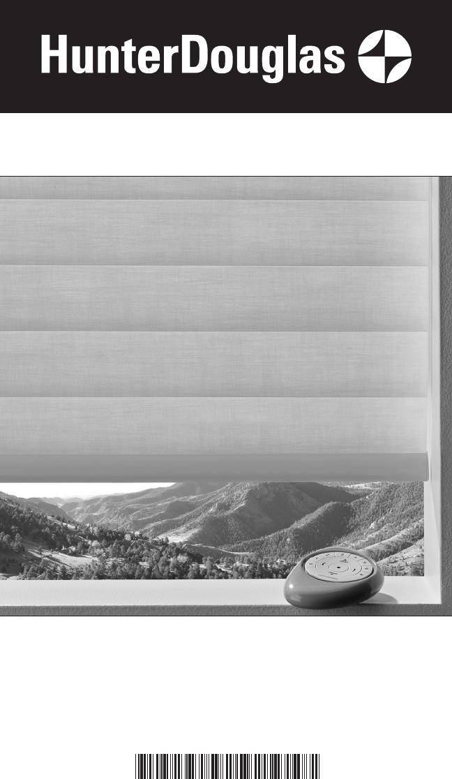
Hunter Douglas Window Fashions ROL2 Motor Control User Manual
Hunter Douglas Window Fashions Motor Control Users Manual
Users Manual
Installation
•
Operation
•
Care
Sonnette
™
Cellular Roller Shades
PowerView® Motorization
5118000018F 5/18

CONTENTS
© 2018 Hunter Douglas. All rights reserved. All trademarks used herein are the property of Hunter Douglas or
their respective owners.
GETTING STARTED:
Product View .....................................................................................................................1
Tools and Fasteners Needed ............................................................................................2
INSTALLATION:
Installation Overview .......................................................................................................3
STEP 1 — Mount the Installation Brackets .....................................................................3
Inside Mount .................................................................................................................4
Outside Mount ..............................................................................................................6
STEP 2 — Install the Shade .............................................................................................8
STEP 3 — Connect the Power Source .............................................................................9
OPERATION:
Testing the Shade ..........................................................................................................14
Basic Operation ..............................................................................................................14
Troubleshooting .............................................................................................................17
CARE:
Removing the Shade ......................................................................................................23
Cleaning Procedures ......................................................................................................23
DECLARATIONS ............................................................................................................25
WARRANTY ......................................................................................................Back Cover
Questions?
Call Hunter Douglas Consumer Support at 1-800-265-8000.
GETTING STARTED
1
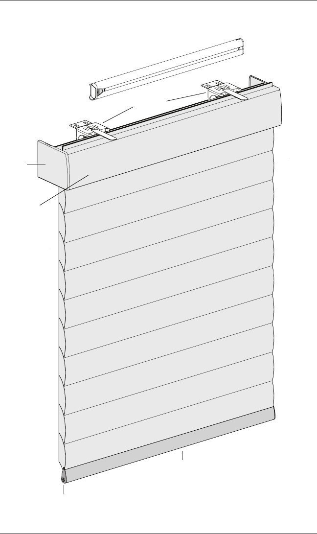
Product View
Installation
Brackets
Bottom Rail
Bottom Rail
End Cap
End Cap
18V Battery Wand
Not Shown:
Satellite Battery Pack, C-Size Satellite Battery Wand,
18V DC Power Supply, and Large DC Power Supply
Headrail
2
GETTING STARTED
Thank you for purchasing Hunter Douglas Sonnette™ cellular roller shades with PowerView®
Motorization. With proper installation, operation, and care, your new shades will provide
years of beauty and performance.
Please thoroughly review this instruction booklet and the enclosed packing list before
beginning the installation.
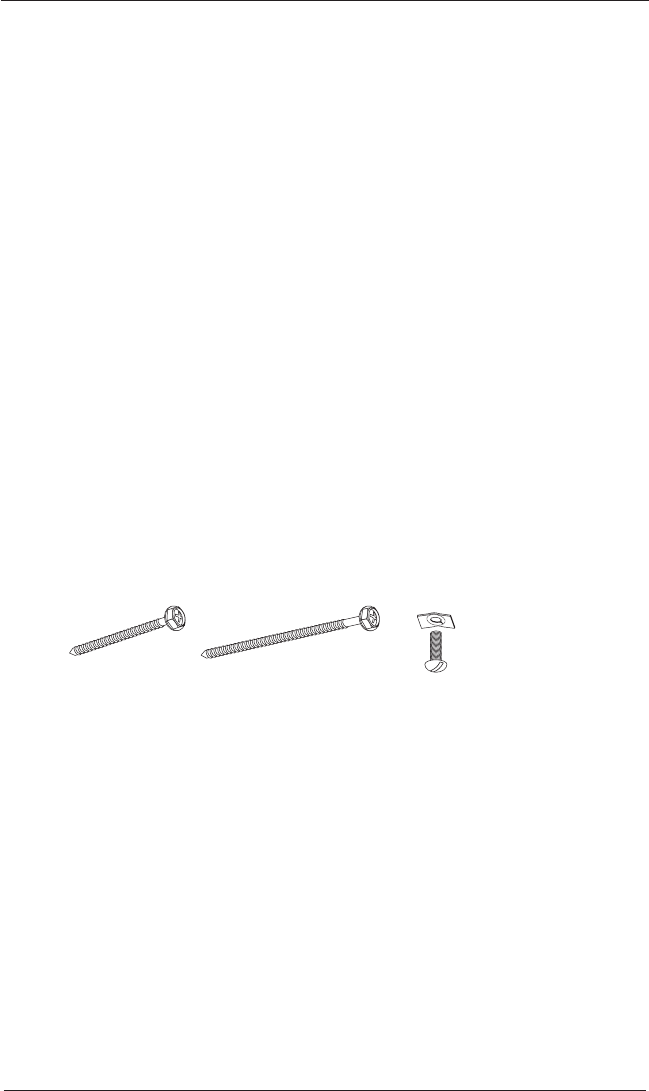
Tools and Fasteners Needed
■ Flat blade and Phillips screwdrivers
■ Level (laser level is recommended)
■ Measuring tape and pencil
■ Pliers
■ Power drill,
3
⁄
32
" drill bit, and
1
⁄
4
" hex driver
■ Scissors (heavy-duty)
In addition, you will need fasteners designed to work with your specific mounting surface(s).
■ #6 Hex Head Screws (Provided). Two 1
1
⁄
2
" screws are provided per installation bracket.
■ Longer #6 Hex Head Screws (Not Provided). If using spacer blocks, use #6 screws
long enough for a secure attachment.
■ Speed Nuts and Screws (Provided). Extension brackets come with screws and
speed nuts.
■ Drywall Anchors (Not Provided). Use drywall anchors when mounting into drywall.
Speed Nut
and Screw
(Two Provided with
Each Extension Bracket)
#6 x 1
1
∕
2
"
Hex Head Screw
(Provided)
Longer #6 Hex Head Screw
for Use with Spacer Blocks
(Not Provided)
INSTALLATION
3
Installation Overview
To install your shade, you will need to perform the following three steps:
STEP 1: Install the Brackets
STEP 2: Install the Shade
STEP 3: Connect the Power Source
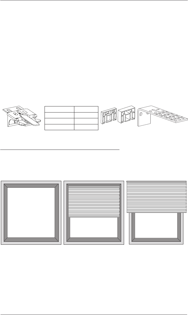
STEP 1 — Install the Brackets
■ Your order will include the correct number of installation brackets for your shade width, as
shown in the table below.
■ Shade orders may also include spacer blocks or extension brackets, if they were specified
for added clearance.
Mounting Types and Window Terminology
If the installation brackets are mounted correctly, the rest of the installation process follows
easily. To prepare for this important first step, review the mounting types and basic window
terminology illustrated below.
■ Refer to the appropriate page below based on your order:
➤ Inside Mount — Page 4
➤ Outside Mount — Page 6
Installation Bracket For Added Clearance
Shade Width Brackets
2
3
4Extension
Bracket
1
∕
4
" or
1
∕
2
"
Spacer Blocks
15" – 36"
36
1
∕
8
" – 79"
79
1
∕
8
" – 84"
Outside Mount
Shading mounts
outside window
opening.
Inside Mount
Shading fits within
window opening.
Collectively, the sill and
jambs are called the
“window casement.”
Molding
Head Jamb
Sill
Jamb Jamb
INSTALLATION
4
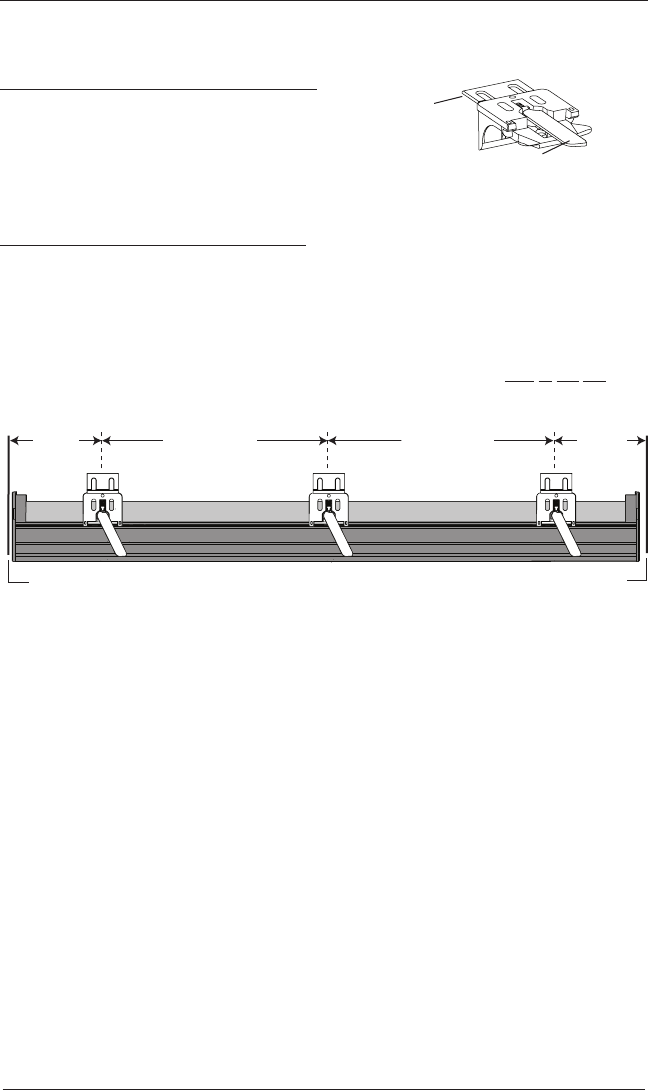
Mount the Installation Brackets — Inside Mount
Prepare the Installation Brackets
■ Use pliers or heavy duty scissors to remove the top
tabs on the installation brackets.
NOTE: Save these tabs once removed. They may be
used as shims, if necessary.
Mount the Installation Brackets
■ Mark 2" to 3" from each jamb for bracket location.
➤ If more than two installation brackets came with your order, space additional bracket(s)
evenly between the two end brackets and mark their location. Mount into wood
whenever possible.
NOTE: Before the headrail is installed, the bracket levers need to be fully to the left and
once the headrail is properly in place, levers click to the right.
Tab
Remove Tab
Back Cover Bracket
Bracket Lever
Space Evenly Space Evenly
2" to 3" 2" to 3"
Jamb Jamb
INSTALLATION
5
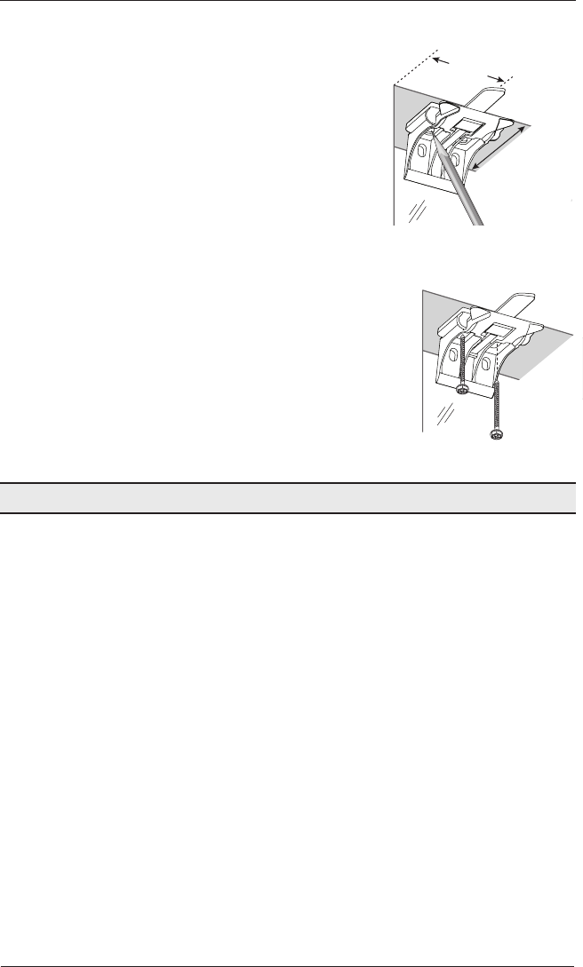
■ Centre the brackets on your marks and mark the location of the screw holes.
➤ The minimum casement depth required for
installation brackets is 1".
➤ The minimum casement depth required for a fully
recessed mount is 3
3
⁄
16
".
■ Use a level to check that the mounting surface is level.
Shim the brackets, if necessary (use the top tab that
was removed from the brackets).
■ Drill the screw holes using a
3
⁄
32
" drill bit.
CAUTION: Use drywall anchors when mounting
into drywall.
■ Attach the installation brackets using the screws provided.
IMPORTANT: Do not overtighten the screws. Check to
ensure the bracket lever can be moved easily side to side.
If not, loosen the screws
in one-eighth turn increments until
the lever can be moved easily.
IMPORTANT: The front edges of the installation brackets
must be level and aligned to eachother.
Proceed to “Install the Shade” on page 8.
2" to 3"
Casement
Depth
INSTALLATION
6
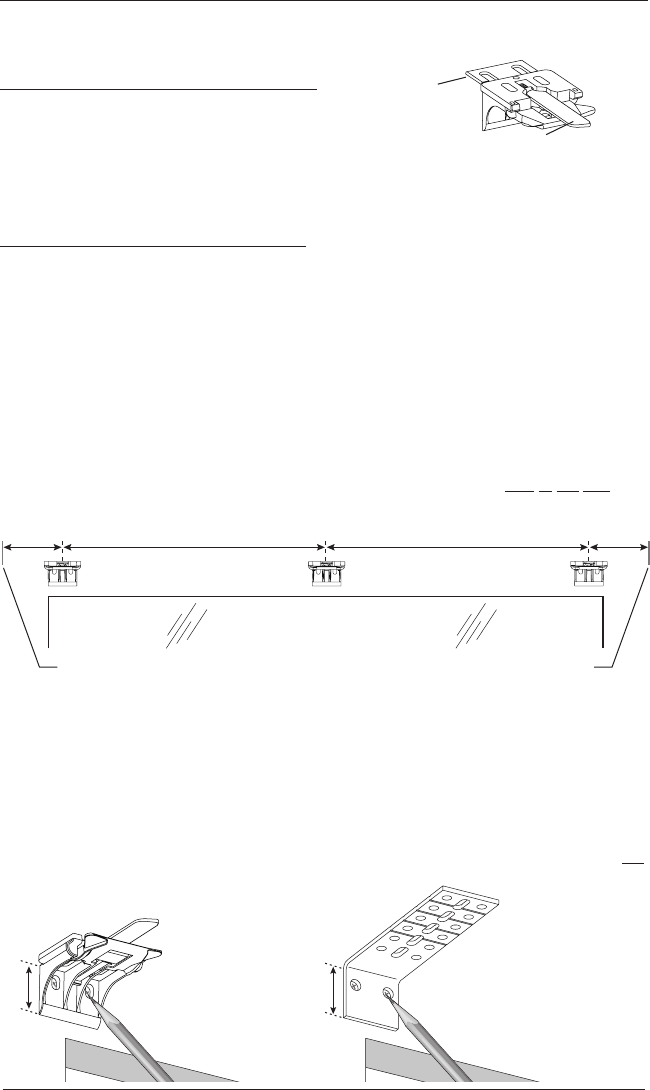
Mount the Installation Brackets — Outside Mount
Prepare the Installation Brackets
■ Use pliers or heavy duty scissors to remove the top
tabs on the installation brackets.
NOTE: Save these tabs once removed. They may be
used as shims, if necessary.
Mount the Installation Brackets
■ Centre the headrail over the window opening at the desired height. Use a pencil to lightly
mark the mounting surface at each end of the headrail.
➤ Alternatively, measure the width of the headrail and use that width to mark the
headrail end points over the window opening.
■ Mark 2" to 3" from each end of theheadrail.
➤ If more than two installation brackets came with your order, space additional bracket(s)
evenly between the two end brackets and mark their location. Mount into wood
whenever possible.
NOTE: Before the headrail is installed, the bracket levers need to be fully to the left and
once the headrail is properly in place, levers click to the right.
■ Centre the installation brackets or extension brackets on your marks and mark where to
drill the screw holes.
➤ A minimum 1
1
⁄
8
" flat vertical surface isrequired for the installation brackets. Extension
brackets require 1
1
⁄
4
".
➤ The top of the installation brackets or extension brackets should be at the desired
height. The brackets should be level andaligned to each other.
CAUTION: The rear of the brackets must be flush against a flat mounting surface. Do not
mount brackets oncurved molding.
Tab
Remove Tab
Back Cover Bracket
Bracket Lever
Window Opening
Space Evenly Space Evenly
2" to 3" 2" to 3"
Headrail End Mark Headrail End Mark
1
1
∕
8
"Extension
Bracket
1
1
∕
4
"
INSTALLATION
7
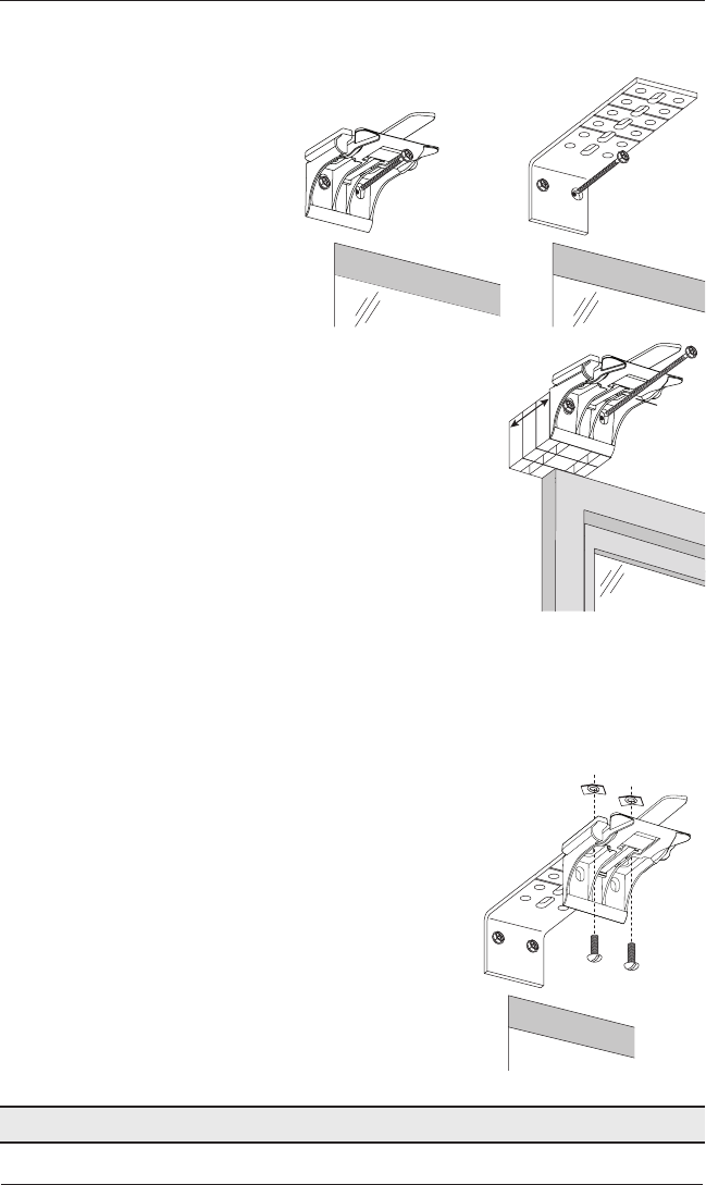
■ Drill the screw holes using a
3
⁄
32
" drill bit.
CAUTION: Use drywall anchors when mounting into drywall.
■ Attach the installation or extension
brackets using the screws provided.
IMPORTANT: The top of the
installation brackets or extension
brackets must be level with their
front edges aligned.
■ If using spacer blocks, attach the spacer block(s) and
installation bracket to a flat vertical mounting surface
with #6screws long enough for asecure installation.
➤ The top of the spacer blocks should be at the
desired shade height.
IMPORTANT: Do not add more than 1
1
⁄
2
" of
clearance using spacer blocks.
IMPORTANT: The tops of the installation brackets
must be level with the front edges aligned.
CAUTION: Use drywall anchors when mounting
into drywall.
■ If using extension brackets, attach an installation bracket
to the underside of each extension bracket using thespeed
nuts and screws provided.
Proceed to “Install the Shade” on page 8.
1
1
∕
2
"
Maximum
Spacer
Blocks
Longer
Screw
Speed Nuts
Screws
INSTALLATION
8
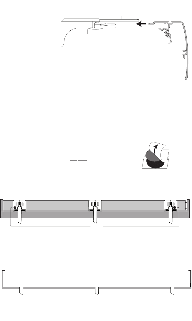
STEP 2 — Install the Shade
■ Position the shade
so that the front
faces you.
■ Ensure that each
lever is pushed to
the left side of the
bracket before installing the shade.
■ Slide the headrail into the installation brackets so that the headrail is between
the lever and the bracket, asshown.
■ Firmly push the headrail into each bracket until it clicks and the levers snap to the right
side of the bracket.
IMPORTANT: Carefully pull on the headrail at each bracket to ensure it is
installedsecurely.
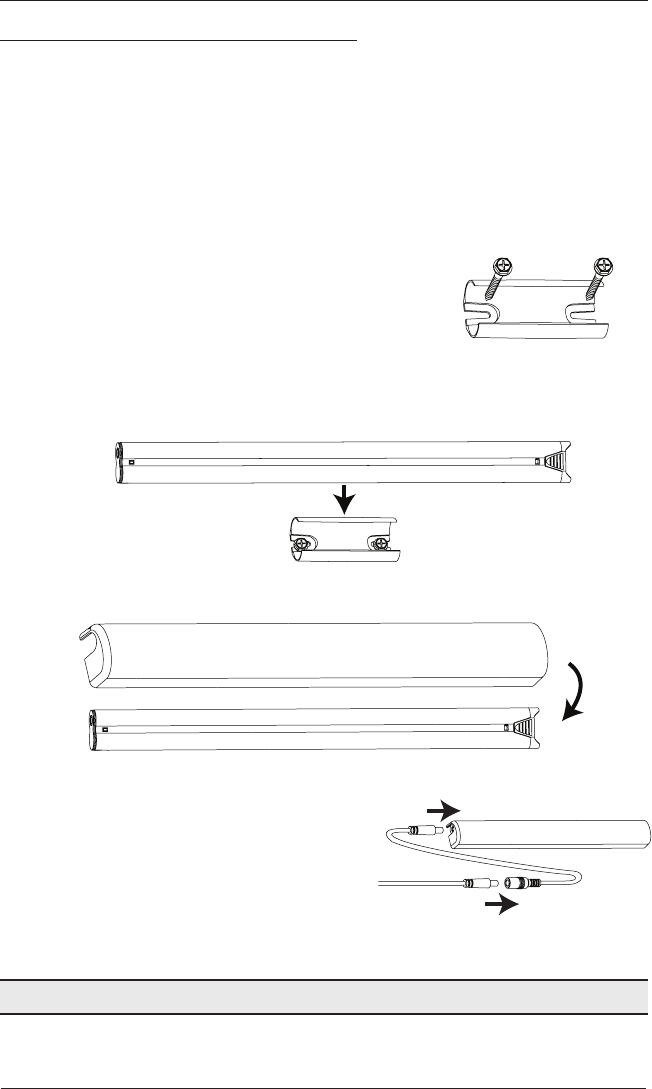
Attach the Dust Cover (Optional for Outside Mounts)
The dust cover is used to protect the top of the headrail from exposure on outside mounted
shades.
■ Cut the dust cover to desired width.
■ Remove the paper backing on one side of the hook and loop
fastener dots.
■ Apply the dots to the installation brackets on each end of the
shades.
■ Remove the remaining paper backing from the dots.
■ Centre the dust cover over the top of the shade, above the dots.
■ Press the dust cover down onto the dots.
Headrail
Installation
Bracket
Lever
Slide the Headrail
Between the Lever
and the Bracket.
Remove
Paper
Backing
Overhead View
No Dust Cover
Dots
Dust Cover Installed
INSTALLATION
9
STEP 3 — Connect the Power Source
NOTE: When power is connected to the motor, a green LED inside the manual control button
housing will flash to indicate the shade is ready for operation.
■ Refer to the appropriate page based on your order.
➤ For a battery wand, see below.
➤ For an optional satellite battery pack, see page 11.
➤ For an optional 18V DC power supply, see page12.
➤ For an optional 18V DC power supply with daisy-chain connections, see page13.
➤ For an optional C-size satellite battery wand or large DC power supply, see the
instructions that came with the unit.
If You Have a Battery Wand...
Install the Batteries into the Battery Wand
NOTE: Hunter Douglas recommends
AA alkaline batteries for use with our
battery-powered shades. These will
provide approximately one year of
operation, depending on usage. Lithium
and rechargeable batteries are not
recommended.
■ Squeeze the cap latch to release
thecap.
■ Remove the cap from the battery
wand.
■ Install the batteries according to the instructions on the battery wand label.
■ Replace the cap.
➤ Align the tab with the slot on the end of the wand.
➤ Press the cap on until it latches.
Slot
Cap
Latch
Battery
Wand
Squeeze
INSTALLATION
10
Install the Battery Wand
NOTE: Battery wand is stored in the front of the headrail. Reference the label on the front of
the headrail for location.
■ Plug the power cable into the battery wand.
■ Lower the shade at least 12" in order to create space to install the battery wand.
■ Locate the clips inside the headrail in front of the fabric roll, as shown.
■ To install, place the wand against the inside of the front of the headrail then push up until
the battery wand locks into place and clicks.
NOTE: Listen for a “click” when installing the battery wand to make sure it is inserted all
the way into the clips.
NOTE: To remove the battery wand, reach your fingers inside the front of the headrail
where the battery wand is located. Find the lip on the end of the wand and pull down.
Proceed to “Testing the Shade” on page14.
Battery
Clip
Headrail Front
Starting Position Installed Position
INSTALLATION
11
If You Have a Satellite Battery Pack...
Install Batteries into the Battery Wand
■ See the instructions on page 9.
Mount the Satellite Battery Pack
■ Decide where you want to mount the satellite battery pack. A satellite battery pack may
be mounted in any orientation.
■ Mark the screw holes for the wall mount bracket.
■ Drill the screw holes using a
3
⁄
32
" drill bit.
■ Remove the backing from the double-sided tape. Press the
bracket into place.
■ Attach the bracket using the screws provided.
■ Position the battery wand so the power cable is easily connected to the socket.
■ Snap the battery wand into the wall mount bracket.
■ Install the battery wand cover with the slot aligned to the socket in the battery wand..
■ Plug the power cable from the shade into
the extension cable.
■ Plug the other end of the extension cable
into the socket in the battery wand.
■ Secure the power supply using wire retainers
(not supplied).
Proceed to “Testing the Shade” on page14.
Wall Mount Bracket
Socket
Battery Wand Cover
Slot
Socket
Battery Wand Cover
Extension
Cable
Power Cable
from Shading
INSTALLATION
12
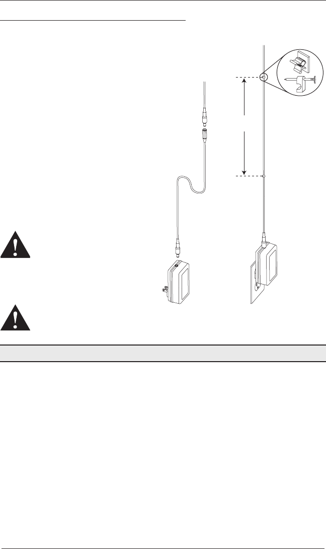
If You Have an 18V DC Power Supply...
Connect the Power Supply
■ Plug the power cable from the shade
into the extension cable.
■ Plug the other end of the extension cable
into the 18V DC power supply.
■ Plug the 18V DC power supply into a
standard outlet.
■ Secure the extension cable using wire
retainers (not supplied). If hiding the
cable behind the shade, make sure
it does not impede the operation of
theshade.
■ Space the wire retainers approximately
15" apart along the power supply cable,
as shown.
WARNING: Keep cables and
small parts out of the reach of
children. They can wrap cables
around their necks and
STRANGLE. They can also put
small parts in their mouths and
CHOKE.
WARNING: Electric shock
and/or a fire hazard may occur, if not properly installed.
Proceed to Testing the Shade” on page14.
Power Cable
from Shading
Extension
Cable
DC
Power
Supply
15"
Maximum
Wire Retainers
INSTALLATION
13
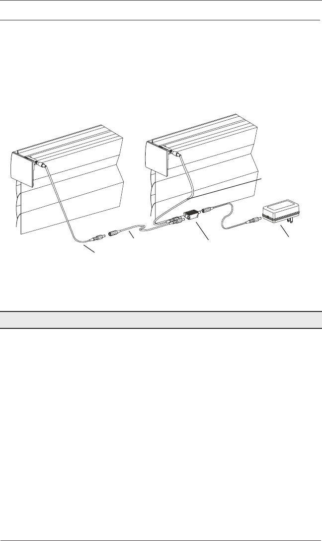
If You Have an 18V DC Power Supply with Daisy-Chain Connections...
The daisy-chain feature allows up to three PowerView® shades to be powered by a single
18V DC power supply. However, each shade can operate independently. The daisy-chain
feature is only available with the 18V DC power supply option.
■ Route the power cable from each shade to the connector, using an extension cable, if
necessary.
■ Plug an extension cable into the connector and plug the cable into the 18V DC power
supply. Two extension cables and two connectors are used for three shades.
■ Plug the 18V DC power supply into a standard outlet.
Proceed to “Testing the Shade” on page14.
Power Cable
from Shade
Power Cable
from Shade
Extension Cable Connector 18V DC
Power Supply
OPERATION
14
Testing the Shade
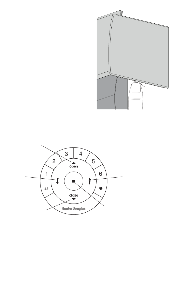
Use the manual control button to test the shade and
ensure that the motor and power source are working
correctly.
■ Press the manual control button to lower the
shade. If the shade does not operate, see
“Troubleshooting” on page 17.
■ Press the manual control button to raise the
shade.
CAUTION: When raising the shade for the first
time, observe how the fabric rolls up into the
headrail. It should roll up evenly. If the bottom
rail is not level or the shade starts to rub against
either window jamb, immediately press the
manual control button to stop the shade. See
“Adjusting the Bottom Rail Weight” on page22.
Using the PowerView® Remote
First, activate the remote by pulling both plastic tabs from the back battery compartment.
IMPORTANT: If you have more than one remote, see “Adding Additional Remote(s) to the
PowerView® Shade Network” in the PowerView Motorization Remote Control Guide.
Group 1
Group 2
OPEN
CLOSE
Group 3
Group 4
Group 5
Group 6
Favorite
(Shading/vane position)
LEFT
ARROW
T
ilts vanes closed
RIGHT ARROW
Tilts vanes open
STOP
(Press and hold for
programming mode)
Manual
Control
Button
End Cap

OPERATION
15
Joining a Shade to a Group
IMPORTANT: The shade will not operate using the remote until it has been joined to
a group.
1. Press and hold ■ STOP for 4 seconds to put the remote in program mode. The lights on the
remote will flash to indicate it is in program mode.
2. Press the desired group number (1 – 6) on the remote. The backlight for the group number
will flash to show it is selected.
3. Press and hold the manual control button on the shade.
4. While continuing to press the manual button, press ▲ OPEN on the remote. The shade will
move slightly to indicate it has joined the group. Release the manual control button.
5. Press and hold ■ STOP for 4 seconds to exit program mode. The lights will stop flashing.
Basic Operation
1. To wake up the remote, simply pick it up or press ■ STOP. The last group(s) selected will be
highlighted and active.
2. Press “all” or groups 1 – 6 to select specific shade(s) to move. Selected group button(s) will
light to show they are selected.
a. Multiple group buttons may be selected at a time.
b. To deselect a group, press the group button again. The backlight for that group button
will go out.
3. Press ▼ CLOSE to lower the selected shade(s).
4. Press ▲ OPEN to raise the selected shade(s).
5. Press ■ STOP to stop shade or vane movement anywhere along its travel.
6. While a shade is in motion, press the opposite of shade motion (▲ OPEN or ▼ CLOSE) to
reverse direction.
7. Press ♥ FAVORITE to send selected shade(s) to your preset “favorite” position. Refer to the
PowerView® Motorization Remote Control Guide on how to set a favorite position.
Operating Tips
1. When the shade is raised, pressing the ▼ CLOSED arrow will first lower the shade.
2. When the shade is lowered, pressing ▲ OPEN will the raise the shade all the way.

OPERATION
16
Further Operation and Programming Information
PowerView® Pebble® Remote and/or PowerView Surface Remote
Operation
For information regarding operation and programming of the PowerView remote, refer to your
PowerView Motorization Remote Control Guide.
PowerView Scene Controller
For information regarding operation and programming of the PowerView Scene Controller,
refer to your PowerView Motorization Scene Controller Guide.
PowerView App Operation
The PowerView Hub is required for PowerView App operation. For information regarding setup
and operation using the PowerView App, refer to the online PowerView App Software Guide
at hunterdouglas.com/powerview/support.
Resetting the Shade (If Necessary)
Basic Reset
The basic reset is used to reset the shade’s travel limits.
1. Press and hold the manual control button for 6 seconds. The shade will move slightly.
2. Release the manual control button. The shade will raise to its fully open position to set the
upper travel limit, then lower to the fully closed position to set the lower travel limit. The
shade will move slightly one more time to indicate that the travel limits have been reset.
Resetting Shade Programming
This reset erases all shade programming from memory, including group assignments,
preventing any input device from operating the shade. Its primary use is during installation to
correct group and network assignments. This reset does not affect travel limits.
1. Press and hold the manual control button for 12 seconds. The shade will move slightly after
6 seconds, then again after 12 seconds. Release the button.
2. Refer to “Joining a Shade to a Group” on page 15 to program the shade to a group.

OPERATION
17
Troubleshooting
If your shade is not operating correctly:
■ First review the guide that came with your control device.
■ Refer to the following troubleshooting procedures for specific solutions for your shade.
If questions remain, please contact Hunter Douglas Consumer Support at 1-800-265-8000.
Problem
The shade will not fit into the installation brackets.
Solution Check that the installation brackets are level and aligned. Adjust and/or shim
to level, if necessary.
Check that the headrail is completely inserted into the installation brackets.
See “STEP 2 — Install the Shade” on page8.
Problem
The shade is hard to raise or lower, or will not raise or lower.
Solution Shades cannot be forced into tight inside mount window openings. If an inside
mount, make sure there is clearance between the ends of the shade and the
window casement.
Check that the installation brackets are level. Shim to level, if necessary.
Problem
The shade does not operate using the manual control button.
Solution Unplug the power cable from the motor, then plug it back in. An LED inside
the manual control button housing should flash GREEN 4 times to indicate the
motor has power.
Check that the batteries in the battery wand, satellite battery pack, or C-size
satellite battery wand are correctly inserted and fresh.
Check that the battery wand, satellite battery pack, C-size satellite battery
wand, or 18V DC power supply is securely connected to the power cable and
the cables are not pinched or caught in the headrail or installation brackets.
Problem
The shade is not responding to the PowerView
®
remote.
Solution IMPORTANT: A shade will not operate using the remote until it has been
joined to a group
Check that the correct group number is selected.
Check that the batteries in the remote are correctly inserted andarefresh.
The LEDs that backlight the remote should come on full bright when ■ STOP
is pressed.
OPERATION
18
Problem
The power cord is positioned for a battery wand instead of a satellite
battery pack or 18V DC power supply.
Solution Reroute the Power Cord
NOTE: The power cord is located in the
front of the shade for an 18V battery wand.
The Satellite Battery Pack and the 18V DC
Power Supply require the power cord to be
rerouted to the back of the shade.
■ If the shade is installed, remove the
shade from the installation brackets.
See “Removing the Shade” on
page 23.
■ Remove the end cap cover on the
control side (the side where the manual
control button is located).
■ Lift the power cord up through the hole
in the end cap, as shown.
■ Pull the cord toward the top of the end
cap and place it in the notch at the top
of the end cap, as shown.
■ Replace the end cap cover and reinstall
the shade.
Top

OPERATION
19
Problem
The bottom rail does not raise or lower completely, or its location when
fully lowered has changed over time.
Solution The batteries may be low in the battery wand, satellite battery pack, or C-size
satellite battery wand. Replace the batteries.
Check that the battery wand, satellite battery pack, C-size satellite battery
wand, or 18V DC power supply is securely connected to the power cable and
the cables are not pinched or caught in the headrail or installation brackets.
Check that there is clearance between the ends of the shade and the window
casement on inside mounts.
Check if the fabric rolls up evenly into the headrail. If not, see “Adjusting the
Bottom Rail Weight” on page22.
Reset the travel limits. See “Adjusting the Limits” on page20.
See the PowerView® Motorization Remote Control Guide for operation or
programming troubleshooting solutions.
Problem
Cells do not align on side-by-side shades.
Solution Cell alignment is only guaranteed within
1
⁄
8
" when shades are ordered at the
same time, at the same height, with the same color and fabric, and when
specified on the order form.
Check that the windows are square and the sameheight.
Problem
Adjacent shades do not roll up evenly.
Solution It is considered normal if the roll-up on both shades is within
5
⁄
16
" of each
other. If one shade rolls up tighter than another, lower and raise both shades
several times.
Reset the shade. See “Resetting the Shade (If necessary)” on page16.
Check that the shade fabric is not catching on any brackets or components.
Check that the fabric winds evenly and does not rub against the headrail. If
uneven, see “Adjusting the Bottom Rail Weight” on page 22.

OPERATION
20
Problem
The shade limits need to be adjusted — upper limit.
Solution Adjusting the Limits
Adjusting the Upper Limit
■ Move the shade to the fully open position. See “Basic Operation” on
page 15.
■ De-select all group numbers on the remote by pressing all group buttons
that show a backlight.
■ While the shade is at the fully open limit position press and hold the
manual control button. See “Testing the Shade” on page 14.
■ While holding the manual control button press and release the ▲ OPEN
button on the remote.
■ Release the manual control button. The shade's light will blink red once
and the shade will move slightly to indicate the shade's upper limit is
ready to be adjusted.
■ Push ▲ OPEN or ▼ CLOSE on the remote and the shade should move
slowly.
NOTE: If the shade does not move slowly, repeat the previous steps.
■ Push the ■ STOP button on the remote once the shade is in the desired
location.
■ Press ■ STOP for 4 seconds to enter programming mode.
■ While the remote is in programming mode, press and hold the manual
control button.
■ Without selecting a number, push the ▲ OPEN button. The shade should
move slightly, indicating the new top limit.
■ To exit programming mode, press and hold the ■ STOP for 4 seconds.
■ Verify the new limit by moving the shade down and then up.

OPERATION
21
Problem
The shade limits need to be adjusted — lower limit.
Solution Adjusting the Limits (Continued)
Adjusting the Lower Limit
■ Move the shade to the fully closed position. See “Basic Operation” on
page 15.
■ De-select all group numbers on the remote by pressing all group buttons
that show a backlight.
■ While the shade is at the fully closed limit position press and hold the
manual control button. See “Testing the Shade” on page 14.
■ While holding the manual control button press and release the ▼ CLOSE
button on the remote.
■ Release the manual control button. The shade's light will blink red once
and the shade will move to indicate the shade's lower limit is ready to be
adjusted.
■ Push ▲ OPEN or ▼ CLOSE on the remote and the shade should move
slowly.
NOTE: If the shade does not move slowly, repeat the previous steps.
■ Press ■ STOP for 4 seconds to enter programming mode.
■ While the remote is in programming mode, press and hold the manual
control button.
■ Without selecting a number, push the ▼ CLOSE button. The shade should
move slightly, indicating the new bottom limit.
■ To exit programming mode, press and hold the ■ STOP for 4 seconds.
■ Verify the new limit by moving the shade up and then down.
OPERATION
22
Problem
The shade raises or lowers unevenly, the bottom rail is not level when fully
raised, or the fabric winds unevenly, or starts to rub against one end of the
headrail.
Solution Keep the bottom rail level while raising the shade. Side-to-side movement
while raising the shade may cause fabric to skew.
Check that the window is square by measuring the diagonals.
Check that the installation brackets are level. Shim to level, if necessary.
If the headrail is level and the window is square, adjust the bottom rail
weight.
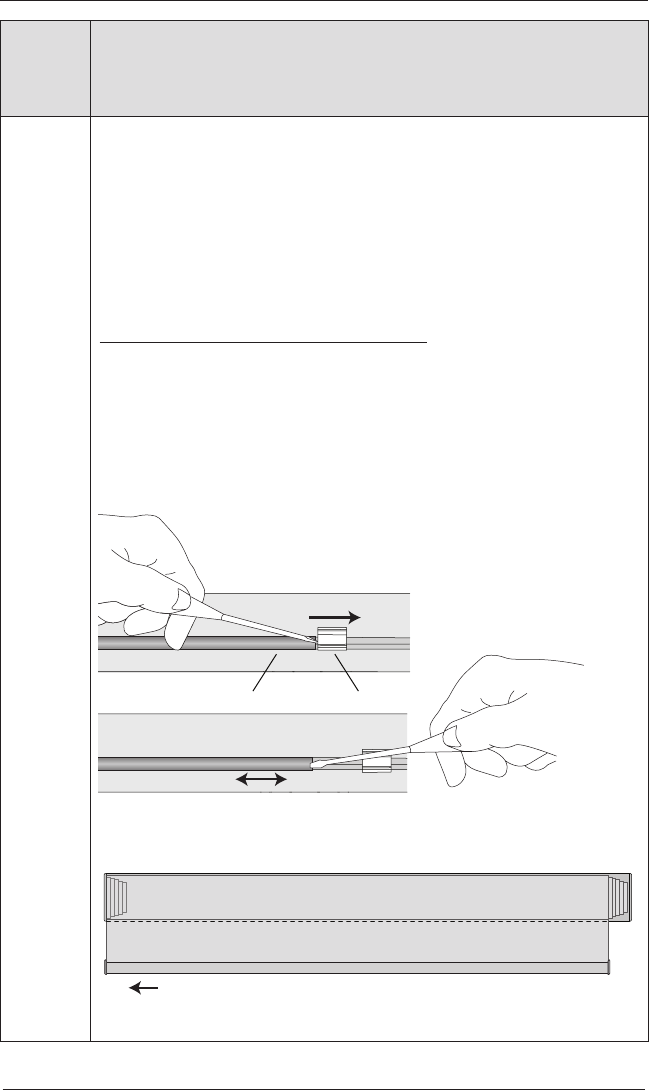
Adjusting the Bottom Rail Weight
IMPORTANT: Only adjust the bottom rail weight if the fabric does not roll up
straight into theheadrail.
First, release both weight locks. On the back of the bottom rail, insert a flat-
blade screwdriver into the slot in each weight lock and slide them away from
the weight.
Slide the weight, in 1" increments, in the direction the fabric is gathering.
Secure the weight by sliding each lock back in position next to the weight.
Test and adjust again, if necessary.
Slide Lock to
Release Weight
Weight Weight Lock
Move Weight
Move Weight
Gathered
Fabric Fabric Roll in Headrail
Bottom Rail
CARE
23
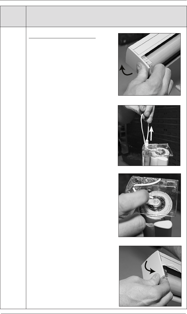
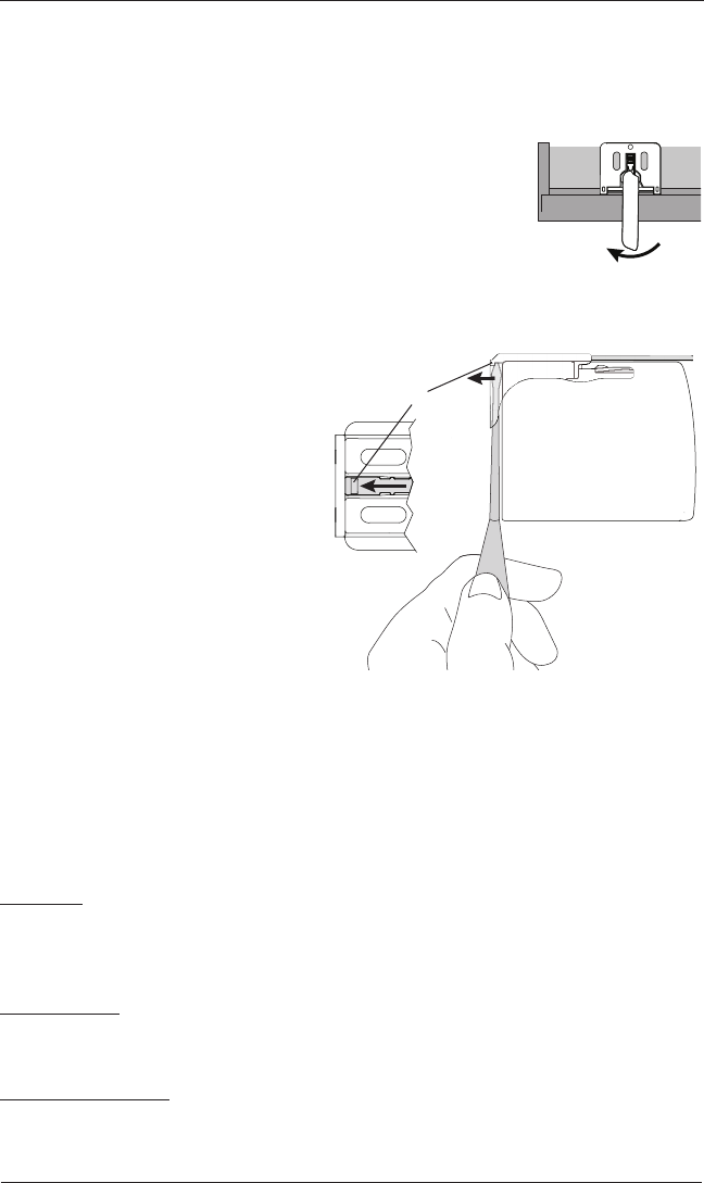
Removing the Shade
■ Fully raise the shade.
■ Disconnect the power source from the power cable at the back
of the shade.
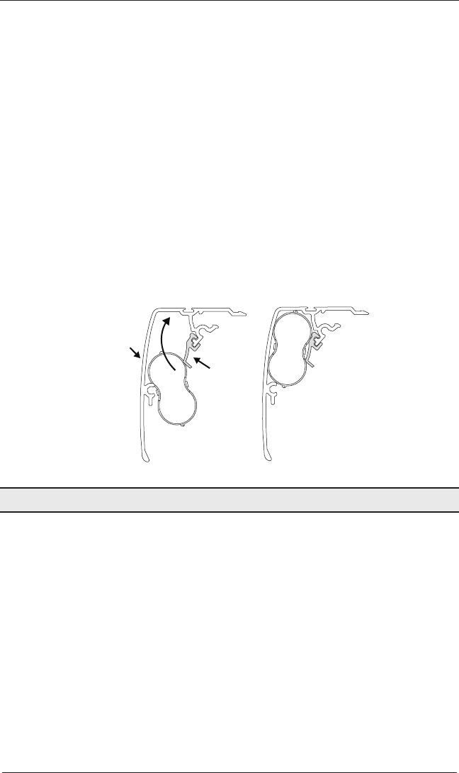
■ Move each lever of the installation brackets to the left to
release the shade.
➤ A flat blade screwdriver can be used to move the lever.
CAUTION: Be very careful not to tear or damage thefabric.
➤ If the lever is inaccessible or
inoperable, lower the shade until
you can see the underside of the
bracket. Carefully reach a small
flat blade screwdriver behind the
shade to the tab on bottom of the
bracket between the screw holes.
➤ Push the tab away from the shade
and pull the headrail to release it
from the bracket.
■ Carefully pull the shade to remove it
from the brackets.
Cleaning Procedures
Sonnette™ Cellular roller shades are made from anti-static, dust-resistant materials which
repel dirt and dust. The following options are available if your shade needs cleaning.
CAUTION: Do not steam the shades.
Dusting
■ Regular light dusting with a feather duster is all the cleaning needed in most
circumstances.
Vacuuming
■ Use a hand-held vacuum with low suction for more thorough dust removal.
Compressed Air
■ Use compressed air to blow dust and dirt off shades.
Move Lever to Left
Top View
Back
Front
Installation Bracket
End Cap
Tab
Underside of
Bracket

CARE
24
Spot-Cleaning
CAUTION: Do not use spot clean treatment on Highline™, Textura™, and Elan®
Metallic fabrics.
■ Prepare a solution of warm water and a mild detergent.
■ Dampen a clean cloth in the solution and wring it out.
■ Dab the spot with the dampened cloth until it is removed. Do not rub the fabric.
■ Allow the shade to dry in the completely lowered position.
Bathtub Cleaning/Water Immersion
CAUTION: Do not immerse the hardware, Elan Metallic, or room-darkening fabrics.
■ Immerse the shade in a basin or bathtub filled with warm water and a mild detergent.
IMPORTANT: Never immerse the headrail into the solution.
■ Rinse with clean water.
■ Before removing from the rinse water, fully raise the shade and tilt it to allow excess
water to drain off.
■ Dry the shade completely in the lowered position.
Injection/Extraction Cleaning
CAUTION: Do not use injection/extraction cleaning on Elan Metallic fabric.
This type of professional cleaning injects a cleaning solution into the fabric and extracts the
dirty solution in the same motion.
A Note About Sonnette™ Fabrics
As with all textiles, Sonnette™ fabric is subject to some variation. Slight wrinkling, puckering,
or bowing is inherent to this textile product and should be considered normal, acceptable
quality. These characteristics are not usually visible from the front or rear but may be visible
from a side angle.

DECLARATIONS
25
U.S. Radio Frequency FCC Compliance
FCC ID information is located underneath the right side end cap.
This device complies with Part 15 of the FCC Rules. Operation is subject to the following two conditions:
(1) This device may not cause harmful interference, and
(2) This device must accept any interference received, including interference that may cause undesired
operation.
This equipment has been tested and found to comply with the limits for a Class B digital device, pursuant
to Part 15 of the FCC Rules. These limits are designed to provide reasonable protection against harmful
interference in a residential installation. This equipment generates, uses and can radiate radio frequency energy
and, if not installed and used in accordance with the instructions, may cause harmful interference to radio
communications. However, there is no guarantee that interference will not occur in a particular installation. If
this equipment does cause harmful interference to radio or television reception, which can be determined by
turning the equipment off and on, the user is encouraged to try to correct the interference by one or more of the
following measures:
• Reorient or relocate the receiving antenna.
• Increase the separation between the equipment and receiver.
• Connect the equipment into an outlet on a circuit different from that to which the receiver is connected.
• Consult the dealer or an experienced radio/TV technician for help.
Any changes or modifications not expressly approved by the party responsible for compliance could void the
user’s authority to operate the equipment.
This equipment complies with FCC radiation exposure limits set forth for an uncontrolled environment and
meets the FCC radio frequency (RF) Exposure Guidelines. This equipment should be installed and operated
keeping the radiator at least 20 cm or more away from person’s body. RF Exposure requirements are met when
installed in mobile equipment. This module cannot be installed in portable equipment without further testing
and a change to FCC’s grant of authorization.
Industry Canada
Under Industry Canada regulations, this radio transmitter may only operate using an antenna of a type
and maximum (or lesser) gain approved for the transmitter by Industry Canada. To reduce potential radio
interference to other users, the antenna type and its gain should be so chosen that the equivalent isotropically
radiated power (e.i.r.p.) is not more than that necessary for successful communication.
This device complies with Industry Canada licence-exempt RSS standard(s). Operation is subject to the
following two conditions: (1) this device may not cause interference, and (2) this device must accept any
interference, including interference that may cause undesired operation of the device.
Class B Digital Device Notice
This Class B digital apparatus complies with Canadian ICES-003, RSS-Gen and RSS-210.
CAN ICES-3 (B)/NMB-3(B)
This equipment complies with IC radiation exposure limits set forth for an uncontrolled environment and meets
RSS-102 of the IC radio frequency (RF) Exposure rules. This equipment should be installed and operated keeping
the radiator at least 20 cm or more away from person’s body.
European Conformity
We, the undersigned,
Hunter Douglas Window Fashions
One Duette Way, Broomfield, CO 80020, USA
Hunter Douglas Europe B.V.
Piekstraat 2, 3071 EL Rotterdam, The Netherlands
certify and declare under our sole responsibility that assembly PV9 conforms with the essential requirements of
the EMC directive 2004/108/EC and R&TTE directive 1999/5/EC.
A copy of the original declaration of conformity may be found at:
www.hunterdouglas.com/RFcertifications.

The Hunter Douglas® Guarantee is designed to ensure a thoroughly satisfying experience when selecting,
purchasing and living with your window fashion products. If you are not thoroughly satisfied with our product,
simply contact Hunter Douglas Canada LP at 1-800-265-8000 in Brampton or visit hunterdouglas.ca.
In support of this policy of consumer satisfaction, Hunter Douglas Canada LP offers the following
Lifetime Limited Warranty.*
Hunter Douglas Canada LP will repair or replace the window fashion product or components found to be defective.
COVERED
BY A LIFETIME LIMITED WARRANTY*
• Hunter Douglas window fashion products are covered for
defects in materials, workmanship or failure to operate for
as long as the original retail purchaser owns the product
(unless shorter periods are provided below)
• All internal mechanisms
• Components and brackets
• Fabric delamination
• Operational cords are covered for 7 years from the date of
of purchase
• Repairs and/or replacements will be made with like or
similar parts or products
• Hunter Douglas motorization components are covered
for 5 years from the date of purchase
NOT COVERED
BY A LIFETIME LIMITED WARRANTY*
• Any conditions caused by normal wear and tear
• Abuse, accidents, misuse or alterations to the product
• Exposure to the elements (sun damage, wind,
water/moisture) or discolouration or fading over time
• Failure to follow our instructions with respect to
measurement, proper installation, cleaning or
maintenance
• Shipping charges, cost of removal and reinstallation
TO OBTAIN WARRANTY SERVICE
1. Contact your original dealer (place of purchase) for warranty assistance.
2. Visit hunterdouglas.ca for frequently asked questions and access to service locations.
3. Contact Hunter Douglas Canada LP at 1-800-265-8000 in Brampton for technical support, certain parts
free of charge, for assistance in obtaining warranty service or for further explanation of our warranty.
Lifetime Limited W
arranty
Except where provincial or territorial law requires otherwise, Hunter Douglas Canada LP and its affiliates:
• will not be able to refund any amount paid by the purchaser to the Hunter Douglas dealer; and
• will not be liable or responsible for any economic loss, expense or fee, damage to property, personal injury, or any
other damage or injury of any kind, including punitive damages, (whether or not suffered by the purchaser or other
persons) arising out of or related to the design, manufacture, fabrication, distribution, purchase, installation, use,
repair or replacement of the Hunter Douglas window fashion product
The limitations of liability in this Lifetime Limited Warranty shall apply regardless of whether Hunter Douglas Canada LP
or its affiliates have breached a warranty or condition of sale, have been negligent in any way, or have committed any
other wrong, whatsoever, except as a result of gross negligence or gross recklessness.
Different warranty periods and terms apply for commercial products and applications.
*Note: You may have different or additional rights under provincial or territorial law.
© 2010 Hunter Douglas ® Registered trademark of Hunter Douglas
Go to the online Reference Guide at hunterdouglas.ca/traderesources for the most up-to-date information. Effective 5/4/10