Hunter Douglas Window Fashions SHT Motor Control User Manual Users Manaul Revised
Hunter Douglas Window Fashions Motor Control Users Manaul Revised
Users Manaul Revised
Installation
•
Operation
•
Care
Palm Beach™ Polysatin™ Shutters
PowerView
®
Motorization Insert
INSTALLATION
1
Now that you have completed your shutter installation, you are ready to program your
PowerView® Shutters.
Connect the Power Source
NOTE: When power is connected to the motor, a green LED inside the manual control button
housing will flash to indicate the louvers are ready for operation.
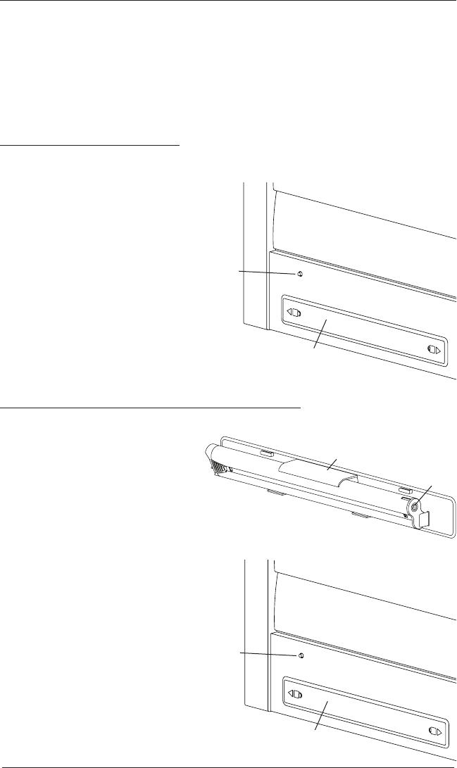
Remove the Battery Cover
NOTE: PowerView shutters with a divider rail or split tilt will have two battery wands, one in
the top rail and one in the bottom rail.
Remove the battery cover plate from
the top and/or bottom rail by sliding in
direction of the unlock icon indicated
on the battery cover.
Plug the Power Cable into the Battery Wand
Locate the power cable inside the rail and plug it into the socket on the battery wand.
Place the battery pack into the clip
on the back of the battery cover.
Insert the battery cover into the rail
and secure it by sliding in the direction
of the lock icon indicated on the battery cover.
Testing the louver section with the manual
control button will allow you to ensure
that the motor and power source are
working correctly.
Press the manual control button
on the back side of the rail to test
operation. If the louvers do not
operate, see “Troubleshooting” on
page 5.
Battery Cover
Manual
Control
Button
Back side of rail
Clip
Socket
Battery Cover
Manual
Control
Button
Back side of rail
Testing the Louver Section
OPERATION
2
Using the PowerView® Remote
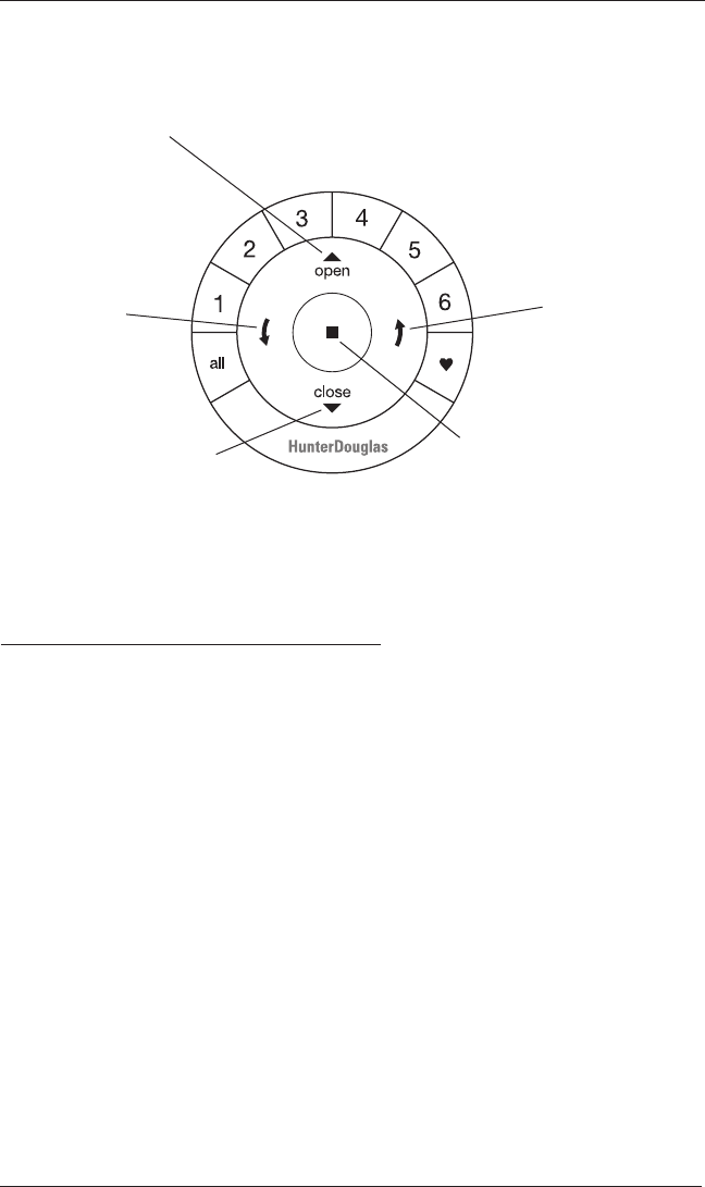
Refer to the illustration below to familiarize yourself with the controls on the remote. Activate
the remote by pulling both plastic tabs from the back battery compartment.
IMPORTANT: If you have more than one remote, see “Adding Additional Remote(s) to the
PowerView® Shade Network” in the PowerView Motorization Remote Control Guide.
Joining a Louver Section to a Group
IMPORTANT: The louver section will not operate using the remote until it has been joined to
a group.
NOTE: If multiple louver sections must be joined to a group, it is recommended that they be
in different groups for individual operation, as well as in the same group for simultaneous
operation. (Note that any louver section can belong to more than one group.) Louver sections
will also operate simultaneously if their individual group buttons are selected, or the “all”
button is selected.
1. Press and hold STOP on the remote until the indicator lights blink (approximately 6
seconds). The remote is now in program mode.
2. Press the desired group number (1 – 6) on the remote. The backlit group number will flash to
show it is selected.
3. While pressing the manual control button on the rail with the corresponding louver section,
press OPEN on the remote. The green light flashes once and the louvers will move
slightly to indicate the louver section has joined the group. Release the manual control
button.
4. Press and hold STOP on the remote until the indicator lights stop blinking (approximately
6 seconds).
Group 1
Group 2
OPEN
Tilt louvers
to the open,
horizontal
position
CLOSE
Tilt louvers to
the closed position
Group 3 Group 4
Group 5
Group 6
Favorite
(Default set at 45 degrees open)
LEFT ARROW
Tilt louvers down
RIGHT ARROW
Tilt louvers up
STOP
(Press and hold for
programming mode)

OPERATION
3
Basic Operation
1. To wake up the remote, simply pick it up or press STOP. The last group(s) selected will be
highlighted and active.
2. Press “all” or groups 1 – 6 to select specific louver sections to move. Selected group
button(s) will light up to show they are selected.
a. Multiple group buttons may be selected at a time.
b. To deselect a group, press the group button again. The backlight for that group button
will go out.
3. Press the left arrow to tilt the louvers down to the closed position.
4. Press the right arrow to tilt the louvers up to the closed position.
5. Press STOP to stop the louver‘s movement anywhere along their travel.
6. While the louvers are in motion, press the opposite of louver‘s motion ( left arrow or
right arrow) to reverse direction.
7. Press OPEN to center the louvers horizontally.
8. Press CLOSE to tilt the louvers to the closed position.
9. Press FAVORITE to send selected louver sections to your preset “favorite” position. Refer
to the PowerView® Motorization Remote Control Guide on how to set a favorite position.
NOTE: OPEN and FAVORITE commands will always rotate the louvers to the fully closed
position to allow for louver alignment before traveling to the selected position.
Further Operation and Programming Information
PowerView® Pebble® Remote and/or PowerView Surface Remote
Operation
For information regarding operation and programming of the PowerView remote, refer to
your PowerView Motorization Remote Control Guide or to the online PowerView Step-by-
Step Guide at hunterdouglas.com/operating-systems/powerview-motorization under
Support.
PowerView Scene Controller
For information regarding operation and programming of the PowerView Scene Controller,
refer to your PowerView Motorization Scene Controller Guide or to the online PowerView
Step-by-Step Guide at hunterdouglas.com/operating-systems/powerview-motorization
under Support.
PowerView App Operation
The PowerView Hub is required for PowerView App operation. For information regarding setup
and operation using the PowerView App, refer to the online PowerView Step-by-Step Guide at
hunterdouglas.com/operating-systems/powerview-motorization under Support.

OPERATION
4
Resetting the Louver Section (If Necessary)
The programming reset erases all louver section programming from memory, including group
assignments, preventing input devices from operating the louver section. The primary use is
to correct group and network assignments during installation. The reset does not affect the
favorite position.
1. Press and hold the manual control button for approximately 12 seconds. The louvers will
move slightly after 6 seconds, then again after 12 seconds. Release the manual control
button (the light flashes red). The light then flashes a series of green and red to indicate
that louver section programming is erased from memory.
2. Refer to “Joining a Louver Section to a Group” on page 2 to program the louver section to a
group.
Troubleshooting
If your louvers do not operate correctly:
With PowerView® shutters, first review the guide that came with your control device.
Refer to the following troubleshooting procedures for specific solutions for your shutters.
Problem
The louvers do not operate using the manual control button.
Solution Unplug the power cable from the motor, then plug it back in. A green LED light
inside the manual control button housing should flash to indicate the motor
has power.
Check that the batteries in the battery wand are correctly inserted and
are fresh.
Check that the battery wand is securely connected to the power cable and the
cables are not pinched or caught in the rail.
Problem The louver section is not responding to the PowerView remote.
Solution IMPORTANT: A louver section will not operate until it is joined to a group.
Check that the correct group number is selected on the remote.
Check that the batteries in the remote are correctly inserted andarefresh. The
LED lights that backlight the remote should come on full bright when STOP
is pressed.
OPERATION
5
Problem The louvers are tilting slowly or do not tilt completely.
Solution The batteries may be low in the battery wand. Replace the batteries.
Check that the battery wand is securely connected to the power cable, and the
cables are not pinched or caught in the rail.
The louver section may need to be reset. Refer to “Resetting the Louver
Section (If Necessary)” on page 4.
Problem The LED light in the manual control button housing signals 8 red blinks.
Solution This is the low battery indicator. Replace the batteries in the battery wand.
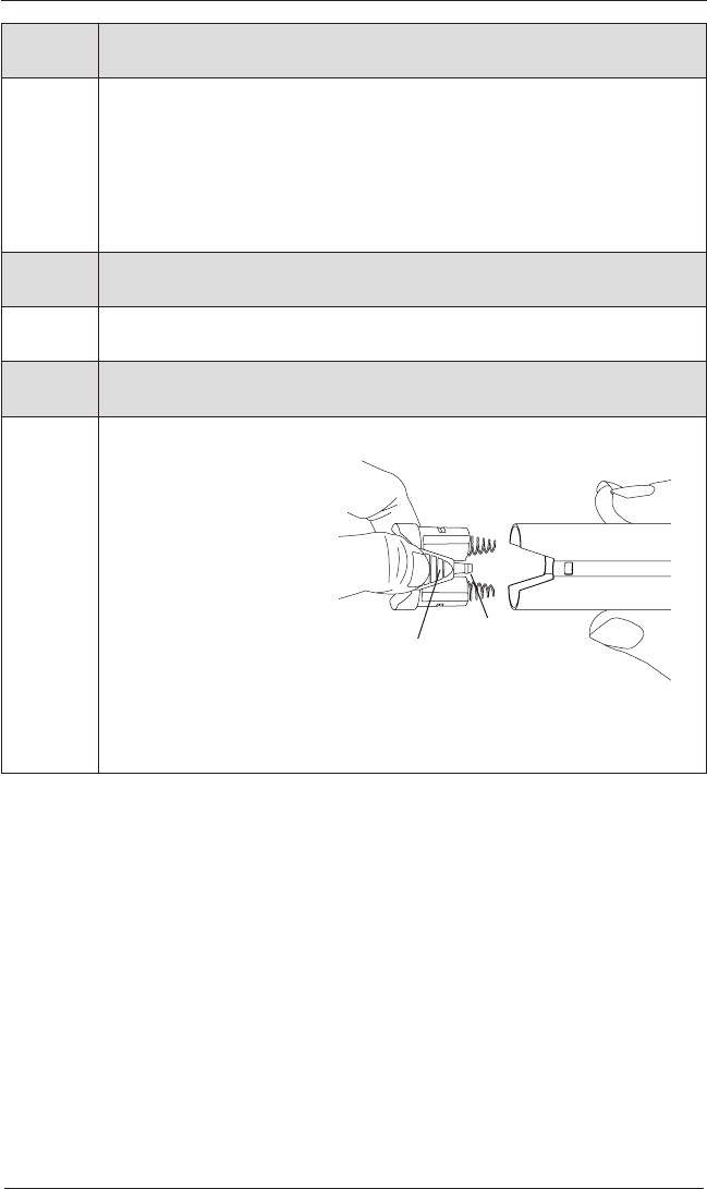
Problem Batteries in the battery wand need to be replaced.
Solution Replace the batteries in the battery wand.
Squeeze the cap latch to
release the cap and remove
the cap from the battery wand.
Install the batteries according
to the instructions on the
battery wand label.
Press the cap on until it
latches.
NOTE:
Hunter Douglas recommends AA alkaline batteries for use with our
battery-powered shadings. These will provide more than one year of operation,
depending on usage. Lithium and rechargeable batteries are not recommended.
Cap
Latch
Battery
Wand
Squeeze
DECLARATIONS
6
U.S. Radio Frequency FCC Compliance
FCC ID information is located on the inside of the battery cover.
This device complies with Part 15 of the FCC Rules. Operation is subject to the following two conditions:
(1) This device may not cause harmful interference, and
(2) This device must accept any interference received, including interference that may cause undesired operation.
This equipment has been tested and found to comply with the limits for a Class B digital device, pursuant to Part
15 of the FCC Rules. These limits are designed to provide reasonable protection against harmful interference
in a residential installation. This equipment generates, uses, and can radiate radio frequency energy and, if not
installed and used in accordance with the instructions, may cause harmful interference to radio communications.
However, there is no guarantee that interference will not occur in a particular installation. If this equipment does
cause harmful interference to radio or television reception, which can be determined by turning the equipment off
and on, the user is encouraged to try to correct the interference by one or more of the following measures:
• Reorient or relocate the receiving antenna.
• Increase the separation between the equipment and receiver.
• Connect the equipment into an outlet on a circuit different from that to which the receiver is connected.
• Consult the dealer or an experienced radio/TV technician for help.
Any changes or modifications not expressly approved by the party responsible for compliance could void the
user’s authority to operate the equipment.
This equipment complies with FCC radiation exposure limits set forth for an uncontrolled environment and
meets the FCC radio frequency (RF) Exposure Guidelines. This equipment should be installed and operated
keeping the radiator at least 20 cm or more away from person’s body. RF Exposure requirements are met when
installed in mobile equipment. This module cannot be installed in portable equipment without further testing
and a change to FCC’s grant of authorization.
Industry Canada
Under Industry Canada regulations, this radio transmitter may only operate using an antenna of a type and
maximum (or lesser) gain approved for the transmitter by Industry Canada. To reduce potential radio interference
to other users, the antenna type and its gain should be so chosen that the equivalent isotropically radiated power
(e.i.r.p.) is not more than that necessary for successful communication.
This device complies with Industry Canada licence-exempt RSS standard(s). Operation is subject to the following
two conditions: (1) this device may not cause interference, and (2) this device must accept any interference,
including interference that may cause undesired operation of the device.
Class B Digital Device Notice
This Class B digital apparatus complies with Canadian ICES-003, RSS-Gen, and RSS-210.
CAN ICES-3 (B)/NMB-3(B)
This equipment complies with IC radiation exposure limits set forth for an uncontrolled environment and meets
RSS-102 of the IC radio frequency (RF) Exposure rules. This equipment should be installed and operated keeping
the radiator at least 20 cm or more away from person’s body.
European Conformity
We, the undersigned,
Hunter Douglas Window Fashions
One Duette Way, Broomfield, CO 80020, USA
Hunter Douglas Europe B.V.
Piekstraat 2, 3071 EL Rotterdam, The Netherlands
certify and declare under our sole responsibility that assembly PV12 conforms with the essential
requirements of the EMC directive 2004/108/EC and R&TTE directive 1999/5/EC.
A copy of the original declaration of conformity may be found at:
www.hunterdouglas.com/RFcertifications.
DÉCLARATIONS
7
Conformité aux règles de la FCC (États-Unis)
Les renseignements sur l’ID de la FCC se trouvent à l'intérieur du couvercle de la batterie.
Ce terminal est conforme à la partie 15 des règles de la FCC. Son fonctionnement est soumis aux deux conditions suivantes :
(1) Ce terminal ne doit pas provoquer de brouillage préjudiciable.
(2) Il doit accepter tout brouillage reçu, y compris le brouillage pouvant entraîner un mauvais fonctionnement.
Cet équipement a été testé et déclaré conforme aux limites imposées aux appareils numériques de la classe B, en vertu de la
partie 15 des règles de la FCC. Ces limites sont conçues pour fournir une protection suffisante contre les interférences nuisibles
dans les installations résidentielles. Cet équipement génère, utilise et peut dégager de l'énergie de radiofréquence et, s'il n'est
pas installé et utilisé conformément aux instructions du fabricant, provoquer un brouillage préjudiciable aux communications radio.
Il n'existe toutefois aucune garantie qu'un équipement particulier ne sera pas victime du brouillage. Si cet équipement entraîne
un brouillage préjudiciable à la réception des émissions radio ou de télévision, identifiable en mettant le terminal hors puis
sous tension, il est recommandé à l'utilisateur de tenter de résoudre ce problème au moyen d'une ou plusieurs des mesures
suivantes :
• Orienter l'antenne réceptrice différemment ou la changer de place.
• Augmenter la distance séparant l'équipement du récepteur.
• Connecter l'équipement à une prise sur un circuit différent de celui sur lequel est branché le récepteur.
• Obtenir de l'aide auprès du revendeur ou d'un technicien radio/TV expérimenté.
Tout changement apporté à ce terminal non expressément approuvé par la partie responsable de la conformité est susceptible
d'annuler le droit de l'utilisateur à se servir de cet équipement.
Cet équipement est conforme aux limites d’exposition aux rayonnements FCC énoncées pour un environnement non contrôlé et
respecte les règles d’exposition aux fréquences radioélectriques (RF) FCC. Cet équipement doit être installé et utilisé en gardant
une distance de 20 cm ou plus entre le radiateur et le corps humain.
Les exigences d’exposition aux RF sont respectées lorsqu’installé dans un équipement mobile. Ce module ne peut pas être
installé dans un équipement portable sans d’autres tests et une modification de l’autorisation de la FCC.
Industry Canada
Under Industry Canada regulations, this radio transmitter may only operate using an antenna of a type and maximum (or lesser)
gain approved for the transmitter by Industry Canada. To reduce potential radio interference to other users, the antenna type
and its gain should be so chosen that the equivalent isotropically radiated power (e.i.r.p.) is not more than that necessary for
successful communication.
This device complies with Industry Canada licence-exempt RSS standard(s). Operation is subject to the following two
conditions: (1) this device may not cause interference, and (2) this device must accept any interference, including interference
that may cause undesired operation of the device.
Class B Digital Device Notice
This Class B digital apparatus complies with Canadian ICES-003, RSS-Gen and RSS-210.
CAN ICES-3 (B)/NMB-3(B)
This equipment complies with IC radiation exposure limits set forth for an uncontrolled environment and meets RSS-102 of the
IC radio frequency (RF) Exposure rules. This equipment should be installed and operated keeping the radiator at least 20 cm or
more away from person’s body.
Industrie Canada
Conformément à la réglementation d’Industrie Canada, le présent émetteur radio peut fonctionner avec une antenne d’un type
et d’un gain maximal (ou inférieur) approuvé pour l’émetteur par Industrie Canada. Dans le but de réduire les risques de brouillage
radioélectrique à l’intention des autres utilisateurs, il faut choisir le type d’antenne et son gain de sorte que la puissance isotrope
rayonnée équivalente (p.i.r.e.) ne dépasse pas l’intensité nécessaire à l’établissement d’une communication satisfaisante.
Le présent appareil est conforme aux normes CNR d’Industrie Canada applicables aux appareils radio exempts de licence.
L’exploitation est autorisée aux deux conditions suivantes : (1) l’appareil ne doit pas produire de brouillage, et (2) l’utilisateur
de l’appareil doit accepter tout brouillage radioélectrique subi, même si le brouillage est susceptible d’en compromettre le
fonctionnement.
Appareil Numérique de Classe B – Avis
Cet appareil numérique de classe B est conforme à la norme NMB-003, CNR-Gen et CNR-210 du Canada.
CAN ICES-3 (B)/NMB-3(B)
Cet équipement est conforme aux limites d’exposition aux rayonnements énoncées pour un environnement non contrôlé et
respecte les règles d’exposition aux fréquences radioélectriques (RF) CNR-102 de l’IC. Cet équipement doit être installé et
utilisé en gardant une distance de 20 cm ou plus entre le radiateur et le corps humain.
Conformité aux règles européennes
Nous, soussignés,
Hunter Douglas Window Fashions
One Duette Way, Broomfield, CO 80020, USA
Hunter Douglas Europe B.V.
Piekstraat 2, 3071 EL Rotterdam, Pays-Bas
attestons et déclarons sous notre seule responsabilité que l'assemblage PV12 est conformes aux exigences essentielles de la
directive CEM 2004/108/EC et de la directive RTTE 1999/5/EC.
Une copie de la déclaration de conformité originale peut être vue à cette adresse :
www.hunterdouglas.com/RFcertifications.