Hunter Douglas Window Fashions STK Motor Control User Manual 121817
Hunter Douglas Window Fashions Motor Control Users Manual 121817
Users Manual 121817
Installation • Operation • Care
Duette® Honeycomb Shades
PowerView® Motorization

CONTENTS
Questions?
Call Hunter Douglas Consumer Support at
1-888-501-8364.
© 2017 Hunter Douglas. All rights reserved. All trademarks used herein are the property of Hunter Douglas or
their respective owners.
Getting Started:
Product View ................................................................ 1
Tools and Fasteners Needed .......................................... 2
Installation:
Installation Overview .................................................... 3
STEP 1 — Install the Brackets ....................................... 3
Mount the Installation Brackets — Inside Mount ............. 4
Mount the Installation Brackets — Outside Mount .......... 7
Mount the Installation Brackets — EndMount ................ 9
STEP 2 — Install the Shade ........................................ 10
STEP 3 — Connect the Power Source .......................... 11
Operation:
Testing the Shade ....................................................... 15
Using the PowerView® Remote ..................................... 15
Resetting the Shade, If Necessary ................................ 18
Level the Rail(s), If Necessary ....................................... 19
Troubleshooting .......................................................... 20
Care:
Removing the Shade, If Necessary ............................... 22
Cleaning Procedures ................................................... 22
Declarations .............................................................. 24
Warranty ......................................................... Back Cover
GETTING STARTED
1
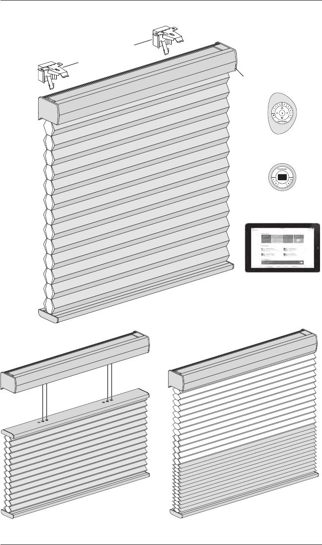
Product View
Top-Down and
Top-Down/Bottom-Up
PowerView®
Standard
Duolite™
Manual
Control
Button
and
LED
Installation Brackets
with Spacer Blocks
PowerView Remote
(with Pebble®)
PowerView Scene
Controller (with Surface)
PowerView App
select
2
GETTING STARTED
Thank you for purchasing Hunter Douglas Duette® honeycomb shades with PowerView®
Motorization. With proper installation, operation, and care, your new shades will provide years of
beauty and performance.
Please thoroughly review this instruction booklet and the enclosed packing list before beginning
the installation.
Tools and Fasteners Needed
■Flat blade and Phillips screwdrivers
■Level (laser level is recommended)
■Measuring tape and pencil
■Power drill,
3
/
32
" drill bit, and
1
/
4
" hex driver
In addition, you will need fasteners designed to work with your specific mounting surface(s).
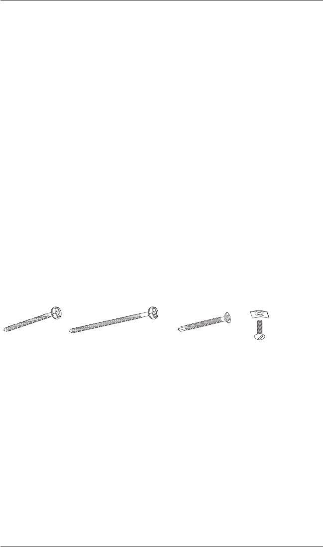
■#6 Hex Head Screws (Provided). Two 1
1
/
2
" screws are provided per installation bracket.
■Longer #6 Hex Head Screws (Not Provided). If using spacer blocks, use #6 screws long
enough for a secure attachment.
■#6 Flat Head Screws (Provided). If end mounting the shade, use two 1
1
/
2
" screws per
installation bracket.
■Speed Nuts and Screws (Provided). Extension brackets come with speed nuts and screws.
■Drywall Anchor (Not Provided). Use drywall anchors when mounting into drywall.
#6 x 1
1
/
2
"
Hex Head Screw
(Provided)
Longer #6 Hex Head Screw
for Use with Spacer Blocks
(Not Provided)
#6 Flat Head Screw
for Use with End Mounts
(Provided)
Speed Nut
and Screw
(Two Provided with
Each Extension Bracket)
INSTALLATION
3
Installation Overview
To install your shade, you will need to perform the following three steps:
STEP 1: Install the Brackets
STEP 2: Install the Shade
STEP 3: Connect the Power Source
STEP 1 — Install the Brackets
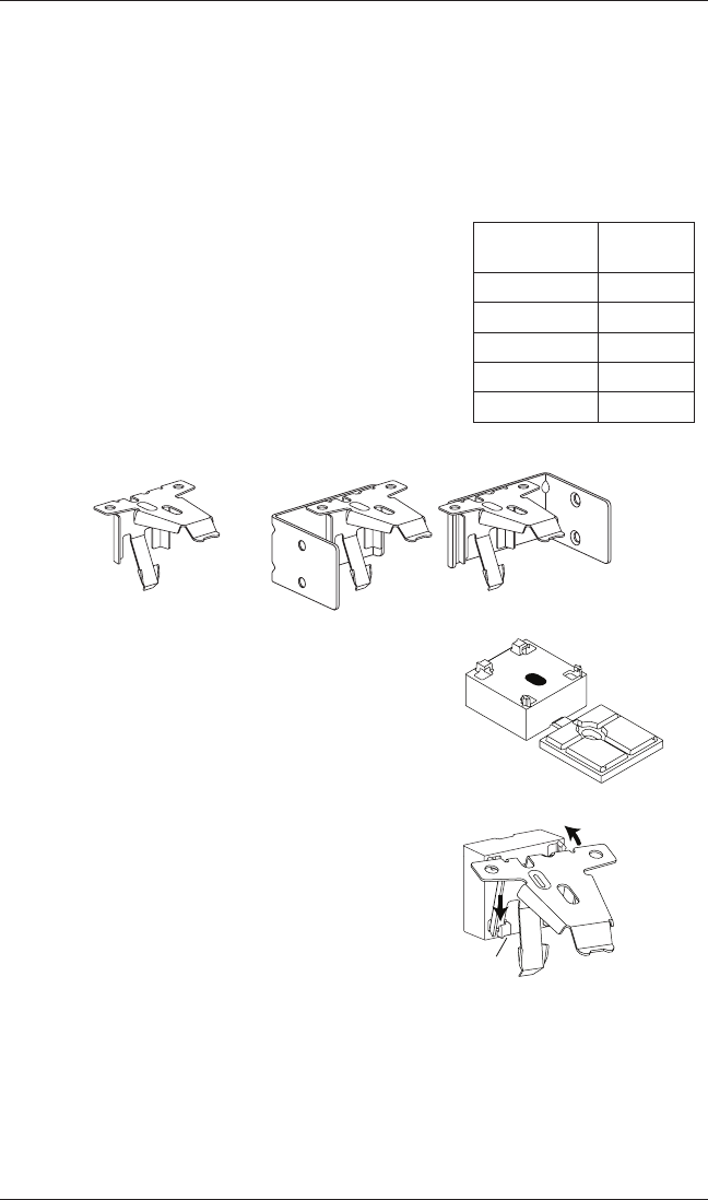
■Your order will include the correct number of installation
brackets for your shade width, as shown in the table.
➤There are two sizes of installation brackets, one for
3
/
8
"
and
3
/
4
" pleat sizes and a larger one for 1
1
/
4
" pleat size.
➤For end mounts, two brackets are used up to the
maximum width of 72".
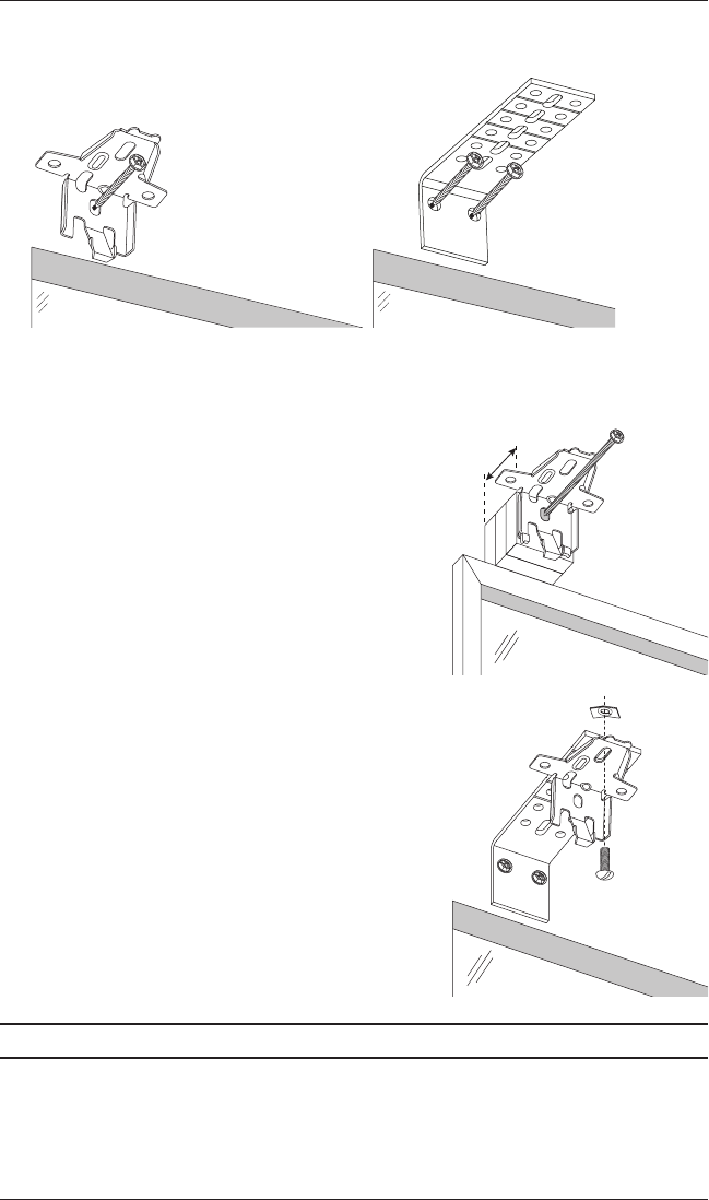
IMPORTANT: A
1
/
2
" spacer block is required for shades
using an attached battery wand. The spacer block is
pre-attached to the back of the installation bracket.
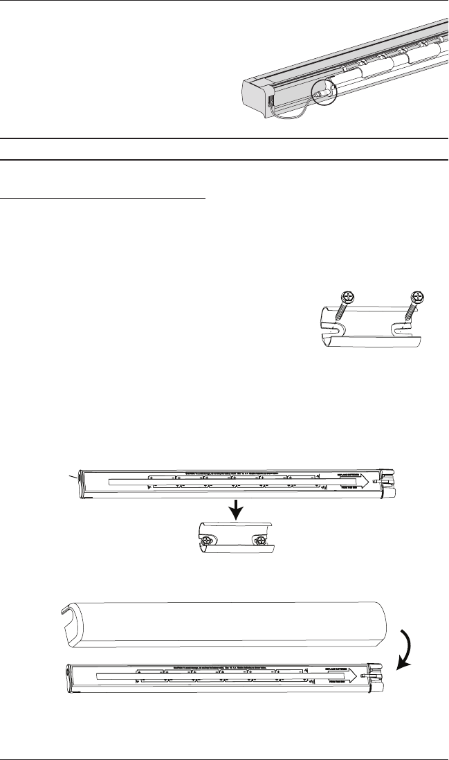
■Should the spacer block become detached, reattach it.
➤Insert the legs of the installation bracket into the
tabs onthespacer block.
➤Rotate the installation bracket back, asshown, to
snap it in place.
Shade
Width
Brackets
Required
12" – 36" 2
36
1
/
8
" – 72" 3
72
1
/
8
" – 108" 4
108
1
/
8
" – 144" 5
144
1
/
8
" – 174" 6
1
/
2
" Spacer Block
1
/
8
" Shim
Installation
Bracket
End Mount
Brackets
Tab
INSTALLATION
4
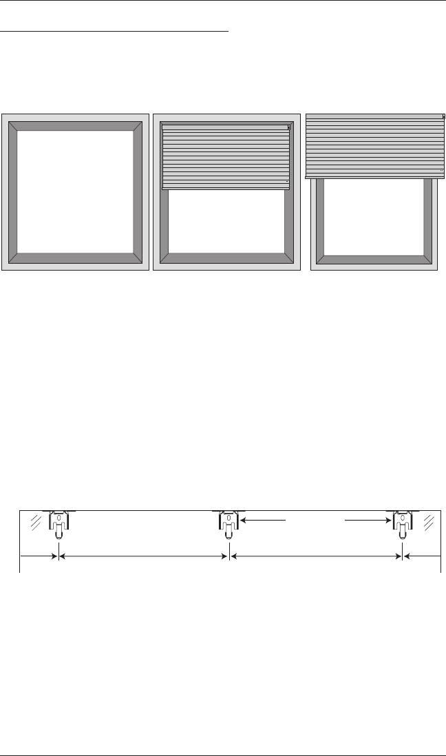
Mounting Types and Window Terminology
If the installation brackets are mounted correctly, the rest of the installation process follows
easily. To prepare for this important first step, review the mounting types and basic window
terminology illustrated below.
■Refer to the appropriate page below based on your order:
➤Inside Mount — Below
➤Outside Mount — Page 7
➤End Mount — Page 9
Mount the Installation Brackets — Inside Mount
■Mark 2" in from each jamb for bracket location.
➤If more than two installation brackets came with your order, space additional bracket(s)
evenly between the two end brackets. Allow a minimum of 15" between the
brackets at the motor end for the battery wand. Mount into wood whenever possible.
Outside Mount
Shade mounts outside
window opening.
Inside Mount
Shade fits within
window opening.
Collectively, the sill and
jambs are called the
“window casement.”
Molding
Head Jamb
Sill
Jamb Jamb
2" Space Evenly
Jamb Jamb
Space Evenly 2"
Minimum 15"
for Battery Wand
INSTALLATION
5
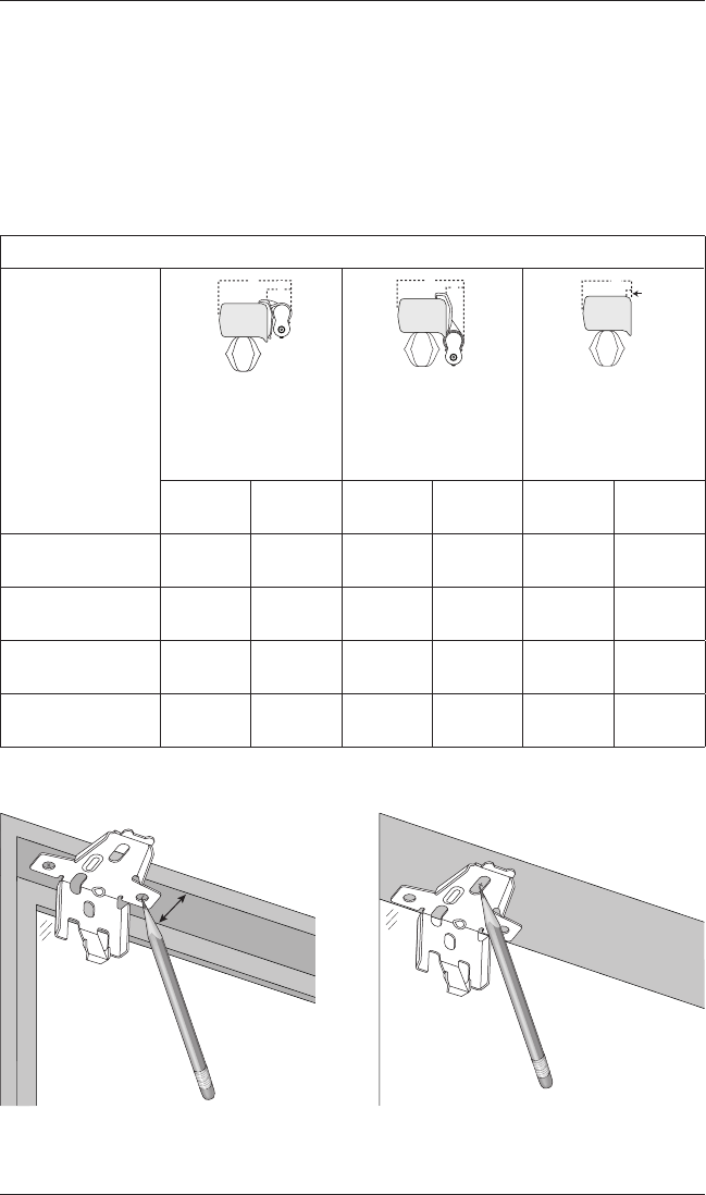
■Center the brackets on your marks, then mark each of the screw holes.
➤Mounting depths vary depending on the fabric pleat size. See the following chart for
minimum and fully recessed depth requirements (measured from the front of the sill to
the back of the installation bracket).
➤Mark both winged screwholes with shallow mounting depths.
➤Mark the center screw hole when depth permits. The center hole requires 1
1
/
2
".
Mounting Depth Requirements
Pleat Size:
Battery Wand
High Mount Bracket
(Standard)
Battery Wand
Low Mount Bracket
(Optional)
Satellite Battery Pack,
C-Size Battery Wand,
18V DC Power Supply,
or Large DC Power
Supply
3
/
8
",
3
/
4
" 1
1
/
4
"
3
/
8
",
3
/
4
" 1
1
/
4
"
3
/
8
",
3
/
4
" 1
1
/
4
"
Minimum mounting
depth: Inside Mount (A) 1" 1" 1" 1"
1
/
2
"
1
/
2
"
Minimum mounting
depth: End Mount 1
3
/
4
" 1
3
/
4
" 1
3
/
4
" 1
3
/
4
" 1
1
/
4
" 1
1
/
4
"
Minimum mounting
depth: Flush Mount (B) 2
3
/
4
" 3
1
/
2
" 2
5
/
8
" 3
3
/
8
" 2
1
/
4
" 3
1
/
8
"
Minimum flat vertical
surface: Outside Mount 1
1
/
4
" 1
1
/
4
" 1
1
/
4
" 1
1
/
4
" 1
1
/
4
" 1
1
/
4
"
A
B
A
B
A
B
A
B
A
B
A
B
A
B
A
B
A
B
See Depth
Chart
Use Center Hole
When Depth Permits
INSTALLATION
6
■Drill the screw holes using a
3
/
32
" drill bit.
CAUTION: Use drywall anchors when mounting into drywall.
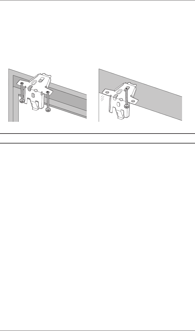
■Use a level to check that the mounting surface is level. Shim the brackets if necessary.
■Attach the installation brackets using the screws provided.
IMPORTANT: The front edges of the installation brackets must be level and aligned. If
mounting to a heavily textured surface, shim the brackets, if needed.
Proceed to “STEP 2 — Install the Shade” on page 10.
INSTALLATION
7
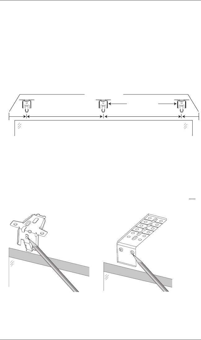
Mount the Installation Brackets — Outside Mount
■Center the headrail over the window opening at the desired height. Use a pencil to lightly
mark the wall at each end of the headrail.
➤Alternatively, measure the width of the headrail and use that width to mark the headrail
end points over the window opening.
■Mark 2" from each end of the headrail.
➤If more than two installation brackets came with your order, space them evenly between
the two end brackets and mark their location. Allow a minimum of 15" between the
brackets at the motor end for the battery wand. Mount into wood whenever possible.
■Center the brackets on your marks, then mark each of the screwholes.
➤A minimum of 1
1
/
4
" flat vertical surface is required to mount the brackets.
➤The top of the installation brackets or extension brackets should be at the desired shade
height. The brackets should be level and aligned.
➤When using extension brackets, mark two screw holes per bracket.
CAUTION: The rear of the brackets must be flush against a flat mounting surface. Do not
mount brackets oncurved molding.
■Drill the screw holes using a
3
/
32
" drill bit.
CAUTION: Use drywall anchors when mounting into drywall.
Headrail End Marks
Window Opening
2" Space Evenly Space Evenly 2"
Minimum 15"
for Battery Wand
INSTALLATION
8
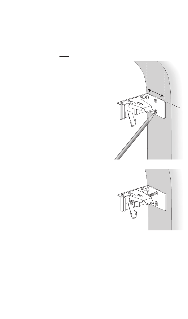
■Attach the installation or extension brackets using the screws provided.
IMPORTANT: The front edges of the brackets
must be level and aligned to each other.
■If using spacer blocks, attach the spacer block/installation bracket assembly to a flat vertical
mounting surface with a #6mounting screw long enough for asecure installation.
➤A maximum of 1
1
/
2
" of spacer blocks per
installation bracket is recommended. Spacer
blocks and shims may be stacked.
➤The top of the spacer blocks should be at the
desired shade height.
CAUTION: Use drywall anchors when mounting
into drywall.
■If using extension brackets, attach an installation
bracket to the underside of each extension bracket
using theprovided screws and speed nuts.
Proceed to “STEP 2 — Install the Shade” on page 10.
Longer Screw
(Not Provided)
Maximum
1
1
/
2
"
INSTALLATION
9
Mount the Installation Brackets — EndMount
End mount the headrail when conventional mounting techniques will not work — for example, in
an arched window opening.
■Position the end mount brackets so that the top of the attached installation brackets are at
the ordered height of the shade.
CAUTION: Both brackets must be installed at the same depth and height.
■Mark both screw holes for each end mount bracket.
➤The mounting surface must be vertical and flat,
not part of an archedcurve.
IMPORTANT: Add
1
/
2
" to the following minimum
mounting depths if a battery wand is used:
➤Minimum mounting depth is 1
1
/
4
" for
3
/
4
" and
3
/
8
"
pleat sizes and 2" for 1
1
/
4
" pleat size. Minimum
mounting depth for a fullyrecessed end mount is
2
3
/
8
" for
3
/
4
" and
3
/
8
" pleat sizes and 3" for 1
1
/
4
"
pleat size.
■Drill the screw holes using a
3
/
32
" drill bit.
■Attach the end mount installation brackets usingthe flat
head screwsprovided.
CAUTION: Drywall mounting is not recommended.
IMPORTANT: For instructions on installing an
arch over a rectangular shade, see the Installation,
Operation, and Care instructions that came with
your arch shade.
Proceed to “STEP 2 — Install the Shade” on page 10.
1
1
/
4
"
Minimum
Ordered
Shade
Height
1
1
/
4
"
Minimum
Ordered
Shade
Height
INSTALLATION
10
STEP 2 — Install the Shade
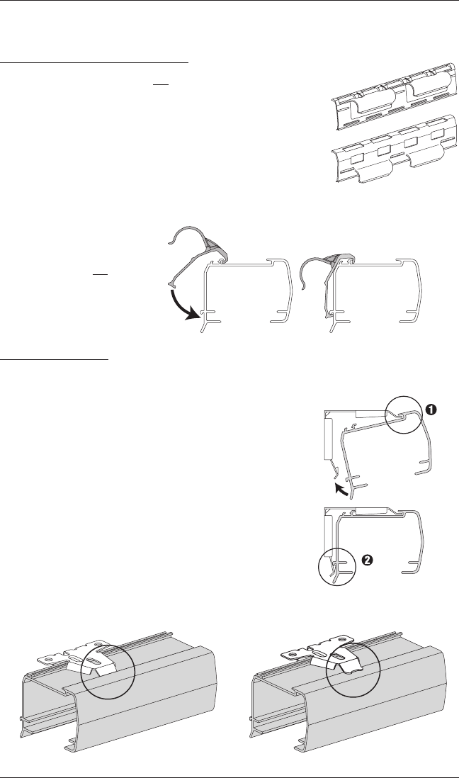
If You Have a Battery Wand Clip...
(Skip this step if your shade will not have an attached
battery wand.)
■Attach the battery wand clip to the headrail.
➤Hook the battery wand clip onto the back
channel ofthe headrail.
IMPORTANT: Position the clip so that the battery
wand will be between installation brackets.
■Rotate the clip down until it
snaps into place.
CAUTION: Do not connect
the battery wand to the
power cable prior to installing
the shade.
Mount the Headrail
CAUTION: Be sure no cables are pinched by the brackets
or headrail during installation; damage or overheating of
components couldresult.
■Fit the front channel on top of the headrail onto the front lip
of the installation brackets.
■Push the headrail up and back until it snaps into place.
➤Check that the bottom of the headrail is snapped into
the base of each bracket.
➤Check that the front lip of each bracket is in the front
channel of the headrail.
■If any brackets are not installed correctly, release the shade
and reinstall. See “Removing the Shade, If Necessary” on
page22.
The back of the headrail
snaps into the bracket.
The front of the bracket
fits under the groove.
Headrail
Bracket
Snap
in Place
Good Bad
High Mount
(Standard)
Battery Wand Clips
Low Mount
(Optional)
F
ront of
Headrail
Battery Wand
Clip
INSTALLATION
11
Socket
STEP 3 — Connect the Power Source
NOTE: When power is connected to the motor, the LED under the manual control button
housing will flash green to indicate the shade is ready for operation.
■Refer to the appropriate page based on your order.
➤For a battery wand, see below.
➤For a satellite battery pack, see page 12.
➤For an optional 18V DC power supply, see page 13.
➤For an optional 18V DC power supply with daisy-chain connections, see page 14.
➤For an optional C-size satellite battery wand or large DC power supply, see the
instructions that came with the unit.
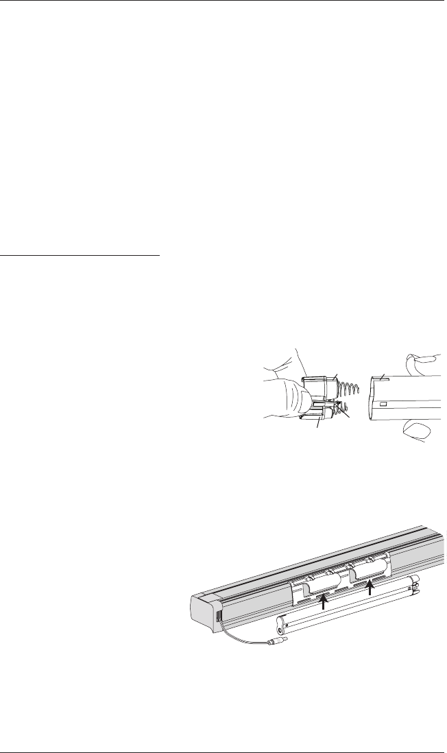
If You Have a Battery Wand...
Install Batteries into the Battery Wand
NOTE: Hunter Douglas recommends AA alkaline batteries for use with our battery-powered
shades. These will provide approximately one year of operation. Lithium and rechargeable
batteries are not recommended.
■Squeeze the cap latch to release thecap and
remove it from the battery wand.
■Install the batteries according to the instructions
on the battery wand label.
■Replace the cap.
➤Align the tab with the end of the wand.
➤Press the cap on until it latches.
Mount the Battery Wand into theBatteryWandClip
■Align the battery wand with its socket toward the motor side end cap.
■Push the battery wand straight up into the battery wand
clip until it snaps into place. Check to make
sure the battery wand is secure.
CAUTION: Be sure the cable does
not become pinched by the battery
wand clip during installation. Damage
or overheating of components could result.
Tab Slot
Cap
Latch
Battery
Wand
Squeeze
INSTALLATION
12
Socket
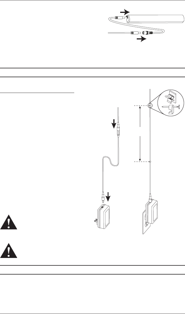
Plug the Power Cable into the Battery Wand
■On the back of the headrail, connect the power cable
(coming from the shade) into the socket on the
battery wand.
Proceed to “Testing the Shade” on page 15.
If You Have a Satellite Battery Pack...
Install Batteries into the Battery Wand
■See the instructions on the previous page.
Mount the Satellite Battery Pack
■Decide where you want to attach the wall mount bracket.
A satellite battery pack may be mounted in any orientation.
■Mark the screw holes.
■Drill the screw holes using a
3
/
32
" drill bit.
■Remove the backing from the double-sided tape. Press the bracket into place.
■Attach the bracket using the screws provided.
■Position the battery wand so the power cable is easily connected to the socket.
■Snap the battery wand into the bracket.
■Install the battery wand cover with the slot aligned to the socket in the battery wand.
Wall Mount Bracket
Socket
Battery Wand Cover
Slot
Socket
INSTALLATION
13
■Plug the power cable from the shade into the
extension cable.
■Plug the other end of the extension cable
into the socket in the battery wand.
■Secure the power supply cable using wire
retainers (not supplied). If hiding the cable behind
the shade, make sure it does not impede the operation of theshade.
Proceed to “Testing the Shade” on page 15.
If You Have a DC Power Supply...
Connect the Power Supply
■Plug the power cable from the shade into the
extension cable.
■Plug the other end of the extension cable
into the DC power supply.
■Plug the DC power supply into a standard
outlet.
■Secure the extension cable using wire
retainers (not supplied). If hiding the cable
behind the shade, make sure it does not
impede the operation of theshade.
■Space the wire retainers approximately
15" apart along the power supply cable,
as shown.
WARNING: Keep cables and small
parts out of the reach of children.
They can wrap cables around their
necks and STRANGLE. They can also
put small parts in their mouths and CHOKE.
WARNING: Electric shock and/or a fire hazard may occur, if not properly installed.
Proceed to “Testing the Shade” on page 15.
Battery Wand Cover
Extension
Cable
Power Cable
from Shade
Power Cable
from Shading
Extension
Cable
DC
Power
Supply
15"
Maximum
Wire Retainers
INSTALLATION
14
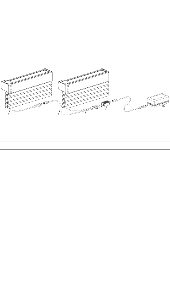
If You Have a DC Power Supply with Daisy-Chain Connections...
The daisy-chain feature allows up to three PowerView® motorized shades to be powered by
a single DC power supply. However, each shade has its own RF receiver and can operate
independently. The daisy-chain feature is only available with the DC power supply option.
■Route the power cables from each shade through the connector, using an extension cable,
if necessary.
■Plug an extension cable into the connector and the DC power supply. A two-shade
configuration is shown below.
■An additional connector and two additional extension cables are used for three shades.
Proceed to “Testing the Shade” on page 15.
Power Cable
from Shade
Extension
Cable
Power Cable
from Shade
Connector
OPERATION
15
Testing the Shade
Testing the shade with the manual control button will allow you to ensure that the motor and
power source are working correctly.
CAUTION: When raising the shade for the first time, observe how the fabric stacks. It should
stack evenly. Immediately stop the shade if the bottom rail is not level or the shade starts to rub
against either window jamb. See “Level the Rails, If Necessary” on page 19.
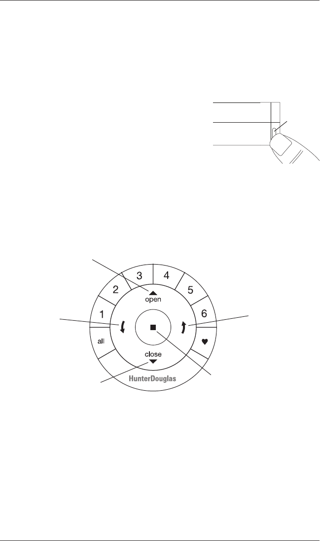
■Press the manual control button on the bottom of the
end cap to test operation. If the shade does not operate,
see “Troubleshooting” on page 20.
➤Press the button to alternately lower, stop, and raise
the shade.
NOTE: With Top-Down/Bottom-Up and Duolite™ shades, the manual control button will
alternately lower the bottom rail, lower the middle rail, raise the middle rail, and raise the
bottom rail.
Using the PowerView® Remote
First, activate the remote by pulling both plastic tabs from the back battery compartment.
IMPORTANT: If you have more than one remote, see “Adding Additional Remote(s) to the
PowerView® Shade Network” in the PowerView Motorization Remote Control Guide.
Manual
Control
Button
Front of
Shade
Group 1
Group 2
OPEN
CLOSE
Group 3
Group 4
Group 5
Group 6
Favorite
(Shade position)
LEFT ARROW
Lowers the middle rail on
Top-Down/Bottom-Up and
Duolite shades
RIGHT ARROW
Raises the middle rail on
Top-Down/Bottom-Up and
Duolite shades
STOP
(Press and hold for
programming mode)

OPERATION
16
Joining a Shade to a Group
IMPORTANT: The shade will not operate using the remote until it has been joined to a group.
1. Press and hold ■ STOP for 4 seconds to put remote in program mode. The lights on the
remote will flash to indicate it is in program mode.
2. Press the desired group number (1 – 6) on the remote. The backlight for the group number
will flash to show it is selected.
3. Press and hold the manual control button on the shade.
4. While continuing to press the manual button, press ▲ OPEN on the remote. The shade will
move slightly to indicate it has joined the group. Release the manual control button.
5. Press and hold ■ STOP for 4 seconds to exit program mode. The lights will stop flashing.
Basic Operation
1. To wake up the remote, simply pick it up or press ■ STOP. The last group(s) selected will be
highlighted and active.
2. Press “all” or groups 1 – 6 to select specific shade(s) to move. Selected group button(s) will
light to show they are selected.
a. Multiple group buttons may be selected at a time.
b. To deselect a group, press the group button again. The backlight for that group button will
go out.
3. Press ▼ CLOSE to lower the selected shade(s).
4. Press ▲ OPEN to raise the selected shade(s).
5. Press ■ STOP to stop the shade’s movement anywhere along its travel.
6. While a shade is in motion, press the opposite of shade motion (▲ OPEN or ▼ CLOSE) to
reverse direction.
7. Press ♥ FAVORITE to send selected shade(s) to your preset “favorite” position. Refer to the
PowerView® Motorization Remote Control Guide on how to set a favorite position.

OPERATION
17
Top-Down/Bottom-Up and Duolite™ Operation
1. Press ▼ CLOSE to lower the bottom rail, closing the shade.
2. Press the left arrow to lower the middle rail. This opens the shade top-down on a Top-
Down/Bottom-Up shade or covers the window with the top fabric panel on a Duolite™ shade.
(If the bottom rail is not fully lowered, pressing this button will lower the bottom rail first then
lower the middle rail.)
3. Press the right arrow to raise the middle rail. This closes the shade bottom-up on a
Top-Down/Bottom-Up shade or covers the window with the bottom fabric panel on a
Duolite shade.
4. Press ▲ OPEN to raise the bottom rail, opening the shade bottom-up. (If the middle rail is not
fully raised, pressing this button will raise the middle rail first then raise the bottom rail.)
5. Press ■ STOP to stop shade movement anywhere along the shade’s travel.
Further Operation and Programming Information
PowerView® Pebble® Remote and/or PowerView Surface Remote Operation
For information regarding operation and programming of the PowerView remote, refer to your
PowerView Motorization Remote Control Guide.
PowerView Scene Controller
For information regarding operation and programming of the PowerView Scene Controller, refer
to your PowerView Motorization Scene Controller Guide.
PowerView App Operation
PowerView Hub is required for PowerView App operation. For information regarding setup
and operation using the PowerView App, refer to the online PowerView App Software Guide at
hunterdouglas.com/powerview/support.

OPERATION
18
Resetting the Shade, If Necessary
Basic Reset
The basic reset is used to reset the shade’s travel limits.
Bottom-Up Shades:
1. Press and hold the manual control button for 6 seconds. The shade will move slightly.
2. Release the manual control button. The shade will raise to its fully open position to set the
upper travel limit, then lower to the fully closed position to set the lower travel limit. The shade
will move slightly one more time to indicate that the travel limits have been reset.
Top-Down Shades:
1. Press and hold the manual control button for 6 seconds. The shade will move slightly.
2. Release the manual control button. The middle rail will raise, closing the shade to set the
upper travel limit, then lower, opening the shade to set the lower travel limit. The shade will
move slightly one more time to indicate that the travel limits have been reset.
Top-Down/Bottom-Up and Duolite™ Shades:
1. Press and hold the manual control button for 6 seconds. The shade will move slightly.
2. Release the manual control button. The middle rail will raise to the top, followed by the bottom
rail, opening the shade bottom-up to set the upper travel limits. The bottom rail will then
lower, followed by the middle rail, opening the shade top-down to set the lower travel limits.
The shade will move slightly one more time to indicate that the travel limits have been reset.
Resetting Shade Programming
This reset erases all shade programming from memory, including group assignments, preventing
any input device from operating the shade. Its primary use is during installation to correct group
and network assignments. This reset does not affect travel limits.
1. Press and hold the manual control button for 12 seconds. The shade will move slightly once
after 6 seconds, then again after 12 seconds. Release the button.
2. Refer to “Joining a Shade to a Group” on page 16 to program the shade to a group.
OPERATION
19
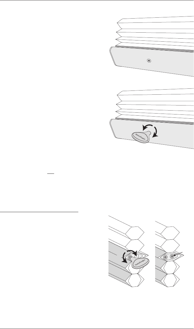
Level the Rail(s), If Necessary
■Lift the bottom rail to locate the pockets on the
underside of the rail.
➤With the middle rail on Top-Down/Bottom-Up
shades, the pockets are on the top side of
the rail.
➤See below for the middle rail adjustment on
Duolite™ shades.
■Gently pull down on the bottom rail (or up on the
middle rail) to fully insert the
7
/
64
" Easy Adjust
key into the pocket. The key is fully inserted
when the base of the key abuts to the pocket.
➤Lift up the rail slightly before turning the
Easy Adjust key. Turn the key clockwise
to raise that side of the rail, or counter-
clockwise to lower it.
➤One quarter turn of the key equals
approximately
1
/
4
".
IMPORTANT: The Easy Adjust key must be fully inserted to avoid stripping the
mechanism. Do not pull down on the rail while turning the key.
■If there are more than two pockets, adjust the outer pockets first. Then adjust inner pockets
as necessary, to maintain equal tension across the rail. As pocket adjustments are made, it
is recommended that the shade be raised and lowered to check that it is level.
Adjusting the Duolite Middle Rail
■Hex pockets are found at the ends of the
middle rail, which is located in the top cell of
the lower fabric panel.
■Insert the Easy Adjust key so that its hex-
shaped portion is about halfway into the pocket.
■Turn the key clockwise to raise that end of the
rail or counter-clockwise to lower it.
➤One full turn of the key equals
approximately
1
/
8
".
■On shades over 60" wide, there will be two hex pockets in the right end of the middle rail.
Use the rear hex pocket to adjust the tension in the center cord after adjusting the outer
cords to level the rail.
Pocket
Underside of Bottom Rail
(or Top Side of Middle Rail)
Raise
Easy Adjust Key
Lower
Raise
Adjusts
Center
Cord
Lower

OPERATION
20
Troubleshooting
If your shade is not operating correctly:
■First review the guide that came with your control device.
■Refer to the following troubleshooting procedures for specific solutions for your shade.
If questions remain, please contact Hunter Douglas Consumer Support at 1-888-501-8364.
Problem The shade will not fit into the installation brackets.
Solution If the shade has a battery wand, check that the wand is not interfering with the
installation brackets.
Check that the installation brackets are level and aligned. Adjust and/or shim to
level, if necessary.
Be sure the heads of the mounting screws are flush against the installation
bracket.
Make sure that the shade fabric is not caught between the installation bracket
and the headrail.
Check that the headrail is completely inserted into the installation brackets. See
“STEP 2 — Install the Shade” on page 10.
Problem The shade does not operate using the manual control button.
Solution Unplug the power cable from the motor, then plug it back in. The LED under
the manual control button housing should flash green to indicate the motor has
power.
Check that the batteries in the battery wand, satellite battery pack, or C-size
satellite battery wand are correctly inserted andfresh.
Check that the battery wand, satellite battery pack, C-size satellite battery wand,
or DC power supply is securely connected to the power cable and the cables are
not pinched or caught in the headrail or installation brackets.

OPERATION
21
Problem The shade is not responding to the PowerView® remote.
Solution IMPORTANT: A shade will not operate until it is joined to a group.
Check that the correct group number is selected.
Check that the batteries in the remote are correctly inserted andarefresh. The
LEDs that backlight the remote should come on full bright when ■ STOP is
pressed.
Problem The shade is operating slowly or does not raise or lower completely.
Solution The batteries may be low in the battery wand, satellite battery pack, or C-size
battery wand. Replace the batteries.
Check that the battery wand, satellite battery pack, C-size satellite battery wand,
or DC power supply is securely connected to the power cable and the cables are
not pinched or caught in the headrail or installation brackets.
Check that the fabric stacks up evenly into the headrail. If not, see “Level the
Rail(s), If Necessary” on page 19.
The shade may need to be reset. Refer to “Resetting the Shade, If Necessary” on
page 18.
Problem The shade raises or lowers unevenly or the bottom rail is uneven when fully
raised.
Solution Lower the shade completely to allow it to “self-correct” skewing.
Check that the headrail and installation brackets are level and aligned. Shim the
installation brackets to level the headrail, ifnecessary.
Adjust the bottom rail. See “Level the Rail(s), If Necessary” on page 19.
CARE
22
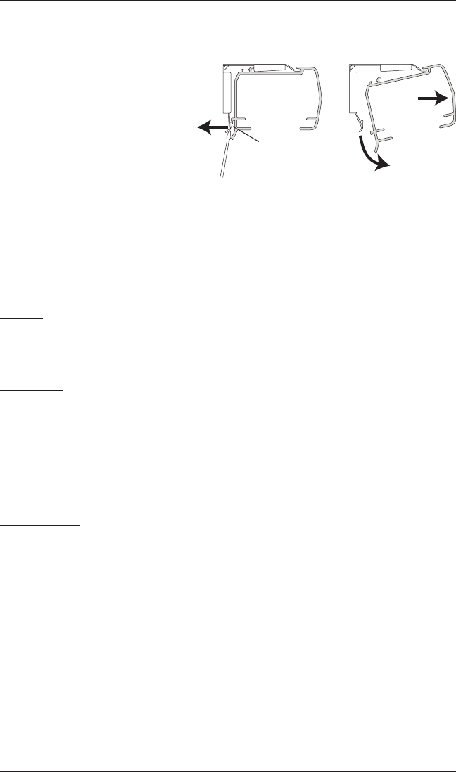
Removing the Shade, If Necessary
■Lower the shade approximately4".
■While holding the headrail, push
back on the bottom tab of the
installation bracket with a flat
blade screwdriver to release the
bottom edge of the headrail.
■After releasing the bottom edge,
roll the back of the headrail down
and out from thebracket.
Cleaning Procedures
Hunter Douglas Duette® honeycomb shades are made of anti-static, dust-resistant fabric which
repels dirt and dust. For most honeycomb fabrics, the following cleaning options are available.
Dusting
■Regular light dusting with a feather duster is all the cleaning that is needed in most
circumstances.
Vacuuming
CAUTION: Do not vacuum Elan® and Myst™ fabrics.
■For deeper cleaning, vacuum gently with a brush attachment.
Compressed Air/Hair Dryer (Cool Setting)
■Use compressed air or a hair-dryer on a cool setting to blow dust and dirt off shades.
Spot-Cleaning
CAUTION: Do not spot-clean Alexa, Commercial, Elan, India Silk, Jardin, Leela, Macon™,
Opalessence™, and all Batiste fabrics.
■Prepare a solution of warm water and a mild detergent.
■Dampen a clean cloth in the solution and wring it out.
■Dab the spot with the dampened cloth until it is removed. Do not rub the fabric.
■Allow the shade to dry in the completely lowered position.
Headrail
Bracket
Back of
Shade Remove
Bottom
Tab

CARE
23
Bathtub Cleaning/Water Immersion
CAUTION: Do not immerse Alexa, Commercial, Elan®, India Silk, Northwood™, Panache™, all
Batiste fabrics, all Alustra® Duette® fabrics, and all opaque fabrics.
■Immerse the shade in a basin or bathtub filled with warm water and a mild detergent.
IMPORTANT: Never immerse the headrail into the solution.
■Rinse with clean water.
■Before removing from the rinse water, fully raise the shade and tilt it to allow excess water
to drain off.
■Dry the shade completely in the lowered position.
Ultrasonic Cleaning
CAUTION: Do not ultrasonically clean Commercial, Myst™, Sheer Opalessence™, and all
opaque fabrics.
■Specify that a mild detergent solution be used.
IMPORTANT: Never immerse the headrail into the solution.
■Dry the shade completely in the lowered position.
Injection/Extraction Cleaning
This type of professional cleaning injects a cleaning solution into the fabric and extracts the dirty
solution in the same motion.
■Use only the dry method of injection/extraction for Elan fabrics.
■If using injection/extraction for Alexa, Batiste Bamboo, and Batiste Textured™ fabrics, specify
that no chemicals are used (wateronly).
Headrail Cleaning
CAUTION: Never use abrasive cleaning methods or harsh chemicals.
■Dampen a soft, clean cloth in warm water and wring it out.
■Gently wipe the headrail to remove dirt and dust.

DECLARATIONS
24
U.S. Radio Frequency FCC Compliance
FCC ID information is located on top of the shade’s headrail.
This device complies with Part 15 of the FCC Rules. Operation is subject to the following two conditions:
(1) This device may not cause harmful interference, and
(2) This device must accept any interference received, including interference that may cause undesired operation.
This equipment has been tested and found to comply with the limits for a Class B digital device, pursuant to Part
15 of the FCC Rules. These limits are designed to provide reasonable protection against harmful interference in a
residential installation. This equipment generates, uses and can radiate radio frequency energy and, if not installed
and used in accordance with the instructions, may cause harmful interference to radio communications. However,
there is no guarantee that interference will not occur in a particular installation. If this equipment does cause
harmful interference to radio or television reception, which can be determined by turning the equipment off and
on, the user is encouraged to try to correct the interference by one or more of the following measures:
• Reorient or relocate the receiving antenna.
• Increase the separation between the equipment and receiver.
• Connect the equipment into an outlet on a circuit different from that to which the receiver is connected.
• Consult the dealer or an experienced radio/TV technician for help.
Any changes or modifications not expressly approved by the party responsible for compliance could void the user’s
authority to operate the equipment.
This equipment complies with FCC radiation exposure limits set forth for an uncontrolled environment and meets
the FCC radio frequency (RF) Exposure Guidelines. This equipment should be installed and operated keeping the
radiator at least 20 cm or more away from person’s body. RF Exposure requirements are met when installed in
mobile equipment. This module cannot be installed in portable equipment without further testing and a change to
FCC’s grant of authorization. Contact Murata regarding portable applications.
Industry Canada
Under Industry Canada regulations, this radio transmitter may only operate using an antenna of a type and
maximum (or lesser) gain approved for the transmitter by Industry Canada. To reduce potential radio interference
to other users, the antenna type and its gain should be so chosen that the equivalent isotropically radiated power
(e.i.r.p.) is not more than that necessary for successful communication.
This device complies with Industry Canada licence-exempt RSS standard(s). Operation is subject to the following
two conditions: (1) this device may not cause interference, and (2) this device must accept any interference,
including interference that may cause undesired operation of the device.
Class B Digital Device Notice
This Class B digital apparatus complies with Canadian ICES-003, RSS-Gen and RSS-210.
CAN ICES-3 (B)/NMB-3(B)
This equipment complies with IC radiation exposure limits set forth for an uncontrolled environment and meets
RSS-102 of the IC radio frequency (RF) Exposure rules. This equipment should be installed and operated keeping
the radiator at least 20 cm or more away from person’s body.
European Conformity
We, the undersigned,
Hunter Douglas Window Fashions
One Duette Way, Broomfield, CO 80020, USA
Hunter Douglas Europe B.V.
Piekstraat 2, 3071 EL Rotterdam, The Netherlands
certify and declare under our sole responsibility that assemblies PV1 and PV5 conform with the essential
requirements of the EMC directive 2004/108/EC and R&TTE directive 1999/5/EC.
A copy of the original declaration of conformity may be found at:
www.hunterdouglas.com/RFcertifications.

5109604488 12/17
The Hunter Douglas® Lifetime Guarantee is an expression of our desire to provide a thoroughly satisfying
experience when selecting, purchasing and living with your window fashion products. If you are not thoroughly
satisfied, simply contact Hunter Douglas at (888) 501-8364 or visit hunterdouglas.com. In support of this policy
of consumer satisfaction, we offer our Lifetime Limited Warranty as described below.
NOTE: In no event shall Hunter Douglas or its licensed fabricators/distributors be liable or responsible for incidental
or consequential damages or for any other indirect damage, loss, cost or expense. Some states do not allow the exclusion or
limitation of incidental or consequential damages, so the above exclusion or limitation may not apply to you. This warranty
gives you specific legal rights, and you may also have other rights which vary from state to state.
Different warranty periods and terms apply for commercial products and applications.
Hunter Douglas (or its licensed fabricator/distributor) will repair or replace the
window fashion product or components found to be defective.
COVERED
BY A LIFETIME LIMITED WARRANTY
• Hunter Douglas window fashion products are
covered for defects in materials, workmanship
or failure to operate for as long as the original
retail purchaser owns the product (unless shorter
periods are provided below).
• All internal mechanisms.
• Components and brackets.
• Fabric delamination.
• Operational cords for a full 7 years from the
date of purchase.
• Repairs and/or replacements will be made with
like or similar parts or products.
• Hunter Douglas motorization components are
covered for 5 years from the date of purchase.
NOT COVERED
BY A LIFETIME LIMITED WARRANTY
• Any conditions caused by normal wear and tear.
• Abuse, accidents, misuse or alterations to the
product.
• Exposure to the elements (sun damage, wind,
water/moisture) and discoloration or fading
over time.
• Failure to follow our instructions with respect
to measurement, proper installation, cleaning
or maintenance.
• Shipping charges, cost of removal and reinstallation.
TO OBTA IN WARRANTY SERV ICE
1. Contact your original dealer (place of purchase) for warranty assistance.
2. Visit hunterdouglas.com for additional warranty information, frequently asked questions and access to service locations.
3. Contact Hunter Douglas at (888) 501-8364 for technical support, certain parts free of charge, for assistance in obtaining
warranty service or for further explanation of our warranty.