Hunter Engineering 45-1125 XF-II Wireless User Manual
Hunter Engineering Company XF-II Wireless
User Manual
©Copyright 2003 - 2006 Hunter Engineering Company
OPERATION INSTRUCTIONS
Form 4925T, 02-06
Supersedes Form 4925T, 09-03
DSP500 Series Wheel
Alignment Sensors

DSP500 Series Wheel Alignment Sensors Contents • i
Contents
1. Getting Started .....................................................................................................1
1.1 About This Manual............................................................................................................... 1
1.2 For Your Safety ................................................................................................................... 1
Hazard Definitions ........................................................................................................ 1
1.3 Care and Cleaning of the Sensors ...................................................................................... 2
1.4 XF Pod (DSP506XF and DSP508XF Sensors Only) .......................................................... 3
Precautions for Systems Equipped with XF Cordless Sensors ................................... 3
1.5 Charging Sensor Batteries (XF Sensors Only) ................................................................... 4
1.6 Vehicle Preparation ............................................................................................................. 7
1.7 Equipment Components and Controls ................................................................................ 7
2. Mounting Sensors................................................................................................9
2.1 Mounting Sensors Onto Wheel Adaptors............................................................................ 9
Wheel Adaptor 175-285-1 .......................................................................................... 10
Wheel Adaptor 175-321-1 with Ratchet Adaptor Locking Lever................................ 11
2.2 Mounting Wheel Adaptors Onto Wheels........................................................................... 13
Wheels With No Rim Lip (Attaching To Outer Rim Lip) ............................................. 13
Wheels With Rim Lip (Attaching To Inner Rim Lip).................................................... 14
2.3 Connecting Sensor Cables................................................................................................ 15
Connecting Sensor Cables With Optional Rack Wiring Kit........................................ 15
Connecting Sensor Cables Without Optional Rack Wiring Kit................................... 15
3. Compensating Sensors .....................................................................................17
3.1 General Compensation ..................................................................................................... 17
3.2 3-Point Compensation....................................................................................................... 17
3.3 2-Point Compensation....................................................................................................... 19
3.4 Rolling Compensation ....................................................................................................... 20
3-Point Procedure ...................................................................................................... 20
2-Point Procedure ...................................................................................................... 21
Procedure Limitations................................................................................................. 22
3.5 Compensation Recall Mode .............................................................................................. 22
4. Operation Information .......................................................................................23
4.1 Adjusting Wheel Adaptor 175-285-1 Lock Lever .............................................................. 23
4.2 Sensor Level Check Procedure ........................................................................................ 24
4.3 Ride Height Measurement (Optional)................................................................................ 25
5. Maintenance .......................................................................................................27
5.1 DSP506XF and DSP508XF Battery Replacement Instructions........................................ 27
5.2 DSP506XF and DSP508XF Hot Swap Battery Replacement Instructions ....................... 28

ii • Contents DSP500 Series Wheel Alignment Sensors
DSP500 Series Wheel Alignment Sensors 1. Getting Started • 1
1. GETTING STARTED
1.1 About This Manual
This manual contains important operation, maintenance, and safety information for the
DSP506, DSP506XF, DSP508, and DSP508XF sensors. It is supplemented by the
alignment system console operation manual. Read and become familiar with the contents
of these publications.
A calibrated set of DSP506, or DSP508, Series Sensors can be used with any Hunter
aligner using WinAlign® software version 7.1 or higher. A calibrated set of DSP506XF, or
DSP508XF Series Sensors can be used with any Hunter aligner equipped with a USB
Electronic Assembly using WinAlign® software version 7.1 or higher.
A calibrated set of DSP506, or DSP508, Series Sensors can be used with 511 Aligners
that have version 2.3 (or above) software.
NOTE: DSP506XF and DSP508XF Series Sensors can not be used with
the 511 Aligners.
1.2 For Your Safety
Hazard Definitions
Watch for these symbols:
CAUTION: Hazards or unsafe practices that could result in minor personal
injury or product or property damage.
WARNING: Hazards or unsafe practices that could result in severe
personal injury or death.
DANGER: Immediate hazards that will result in severe personal injury
or death.
These symbols identify situations that could be detrimental to your safety and/or cause
equipment damage.
IMPORTANT SAFETY INSTRUCTIONS
Read all instructions.
Do not operate equipment with a damaged cord or if the equipment has been dropped or
damaged until it has been examined by a qualified service representative.
Do not let cord hang over edge of table, bench or counter or come in contact with hot
manifolds or moving fan blades.
If an extension cord is necessary, a cord with a current rating equal to or more that that of
the equipment should be used. Cords rated for less current than the equipment may

2 • 1. Getting Started DSP500 Series Wheel Alignment Sensors
overheat. Care should be taken to arrange the cord so that it will not be tripped over or
pulled.
Always unplug equipment from electrical outlet when not in use. Never use the cord to
pull the plug from the outlet. Grasp plug and pull to disconnect.
Let equipment cool completely before putting away. Loop cord loosely around equipment
when storing.
To reduce the risk of fire, do not operate equipment near open containers of flammable
liquids (gasoline).
Keep hair, loose clothing, neckties, jewelry, fingers, and all parts of body away from all
moving parts.
To reduce the risk of electrical shock, do not use on wet surfaces or expose to rain.
Use only as described in this manual. Use only the manufacturer’s recommended
attachments.
ALWAYS WEAR OSHA APPROVED SAFETY GLASSES. Eyeglasses that only have
impact resistant lenses are NOT safety glasses.
SAVE THESE INSTRUCTIONS
Read and follow all caution and warning labels affixed to equipment and tools.
Use caution when jacking the vehicle up or down.
Misusing this equipment can shorten the life of the equipment. To prevent accidents
and/or damage to the sensors, use only Hunter recommended accessories.
Remove the sensors from the wheels before moving the vehicle. When sensors are not
in use, store them on the sensor cabinet.
1.3 Care and Cleaning of the Sensors
When cleaning the sensors, use a mild window cleaning solution to wipe off the sensors
and adaptors.
CAUTION: Do not hose down or submerge the sensors in water. Do not
spray cleaner on the sensor. This could damage the electrical
system and optical components.
Keep wheel adaptor rods cleaned and lubricated. Lubricate as needed with a coating of
light lubricant such as WD-40.
CAUTION: Do not lubricate the center screw shaft of the wheel adaptor.
DSP500 Series Wheel Alignment Sensors 1. Getting Started • 3
1.4 XF Pod (DSP506XF and DSP508XF Sensors Only)
The DSP506XF and DSP508XF sensors communicate with the aligner console using
Extra High Frequency (XF). Radio waves are transmitted and received from the sensors
and the XF Pod.
Occasionally the XF Pod may receive interference from electronic devices in the
neighborhood (microwaves). The DSP506XF and DSP508XF sensors and XF Pod may
be configured to use different radio frequencies to minimize interference.
The XF system transceiver generates power radio waves in the range of 2.4 GHz. Radio
waves at these frequencies reflect off most objects, resulting in an indoor and outdoor
range of approximately 100 feet (30 meters).
Interference has occurred when the XF Pod does not receive the radio waves. If this
happens, move the mobile cabinet approximately 2 or 3 inches (51 or 76 mm) in any
direction.
Temporary interference problems can be bypassed by connecting the sensors to the
aligner console with the sensor cables.
Precautions for Systems Equipped with XF Cordless Sensors
The following precautions apply to the XF transceivers installed in the aligner console
and the alignment sensors as part of the XF cordless sensor option.
Operation is subject to the following two conditions: (1) this device may not cause
interference, and (2) this device must accept any interference, including interferences
that may cause undesired operation of the device.
WARNING: This equipment has been tested and found to comply with
the limits for a Class A digital device, pursuant to Part 15 of
the FCC Rules. These limits are designed to provide
reasonable protection against harmful interference when
the equipment is operated in a commercial environment.
This equipment generates, uses, and can radiate radio
frequency energy and, if not installed and used in
accordance with the instruction manual, may cause harmful
interference to radio communications. Operation of this
equipment in a residential area is likely to cause harmful
interference in which case the user will be required to
correct the interference at his own expense.
WARNING: Changes or modifications not expressly approved by the
manufacturer could void the user’s authority to operate the
equipment.
4 • 1. Getting Started DSP500 Series Wheel Alignment Sensors
1.5 Charging Sensor Batteries (XF Sensors Only)
Each sensor contains a 12VDC sealed lead acid rechargeable battery. To get the
maximum life out of the batteries in the sensors, follow these three rules:
1. If the sensors are not in use, charge them.
2. Switch sensors “OFF” during charging if you are using cables.
3. Charge for eleven to thirteen hours, and/or provide an extended charge time
(24 hours or longer) at least once a week.
NOTE: Make sure the main power switch at the rear of the console is
left “ON” and the outlet that supplies power to the aligner is on.
“K”, “R”, and “P” cabinets are equipped with a computer, printer
and CRT, but still provide power to the charging stations when
using the standby power switch. This standby power switch is
located on the front or side of the cabinet.
The “S”, “SMT-CKD” and “W” cabinets do not have a standby
power switch. The computer, printer, and CRT may be switched
“OFF” independently from the main power switch.
To prevent premature degradation of battery performance, the charger has to replace
125% of the energy that was removed from the battery. It is not necessary to fully
discharge the batteries before charging. However, it is important they be charged
fully.
Charging information:
To recharge the batteries when the sensors are not in use, place the wheel adaptor
sensor assemblies on the cabinet storage hanger and leave the main aligner power on.
The “shoe” on which the sensor hangs acts as the – (neg) terminal, and the insulated
contact is the + (pos) terminal.
CHARGE INDICATOR
Any time batteries are being charged the charge indicator light on the sensor will be
illuminated.

DSP500 Series Wheel Alignment Sensors 1. Getting Started • 5
The charge indicator light turning from red to yellow is an indication that the charging
mode has switched from a fast charge mode into a “trickle” charge mode. It does not
mean that the battery is 100% charged. A fully discharged battery should be allowed to
“trickle” charge a minimum of five hours to ensure a full charge. The charge indicator
light turns green after approximately 6-8 hours of trickle, indicating the charger has
entered “float” mode, which maintains the battery at full charge indefinitely.
You should expect at least 8 hours of continuous use from a fully charged battery.
If you are not getting this amount of usage time, the most likely cause is inadequate charging
time.
Batteries that are consistently subjected to partial charging rather than full charge cycles will
permanently lose capacity.
Charging time for a fully discharged battery with the sensor power switch turned “OFF” is 11
to 13 hours. Three or four times this interval would be required if the sensors were left “ON”
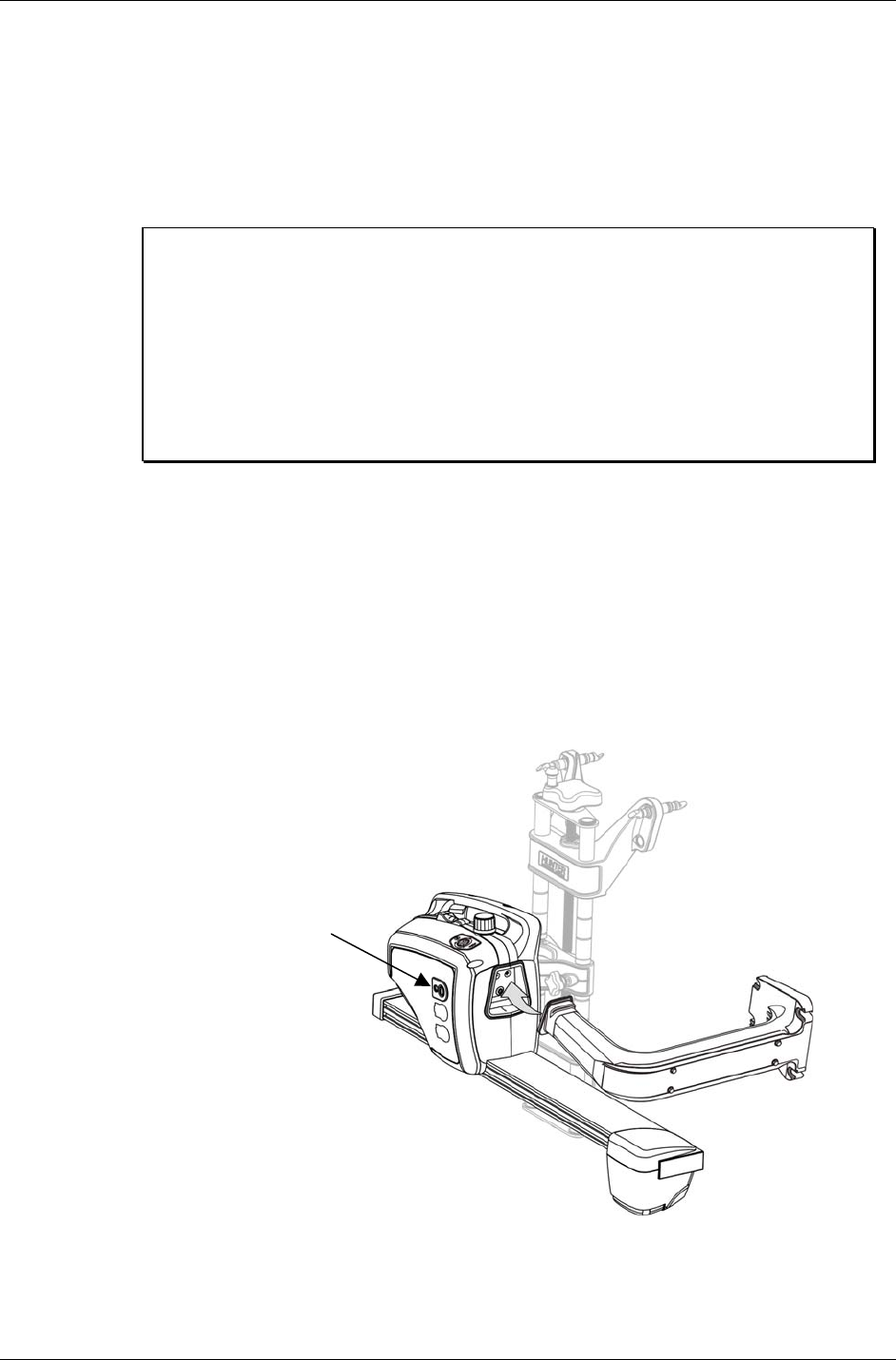
during the charge cycle. It is very important that the sensors be turned “OFF” during
charging. The sensor’s power switch is located on the front of the sensor above the two
cable connectors. When the sensor is placed on the storage hanger, it will automatically turn
off.
Charging overnight with the sensors’ power switches set to “OFF” will provide a proper
charge.
Our charging system cannot over-charge the batteries. If you’re not using the
sensors, charge them!
The sensor batteries are rated for 200 full charge/discharge cycles, making their life
expectancy about one year for the customer that consistently discharges them 100%. Life
expectancy for batteries with lower usage can be significantly longer.
100% Discharge 200 Cycles
50% Discharge 450 Cycles
30% Discharge 1000 Cycles
In a shop with extended service hours, there are some things you can do to prolong battery
life:
When the sensors are not being used to perform alignments, they should be stored on the
charging hangers with sensor power switched off. At a minimum, turn the sensors “OFF”
between alignments. Any charging accomplished throughout the day helps maintain the
batteries at peak performance, and helps extend their life.
If you have one day out of the week when alignments are not performed, you can let the
sensors charge continuously for 24 hours or longer. This should “undo” the effects of any
undercharging that occurred during the previous week. This sort of prolonged charging will
only be effective at restoring full capacity to the batteries if performed regularly. Once a week
is the recommended minimum.
When is it time to replace the batteries?
If after a full charge the battery does not last for the expected 8 hours, you should put it
through one or two sessions of extended charge time (24 hours or longer). If the battery does
not recover and start giving satisfactory cycle time, then it should be replaced. The sooner
you catch the batteries losing capacity, the more likely an extended charge time will restore
the battery to normal capacity. If the battery discharge time is only three or four hours, it is
unlikely, that extended charge time will help significantly.
6 • 1. Getting Started DSP500 Series Wheel Alignment Sensors
Additional information:
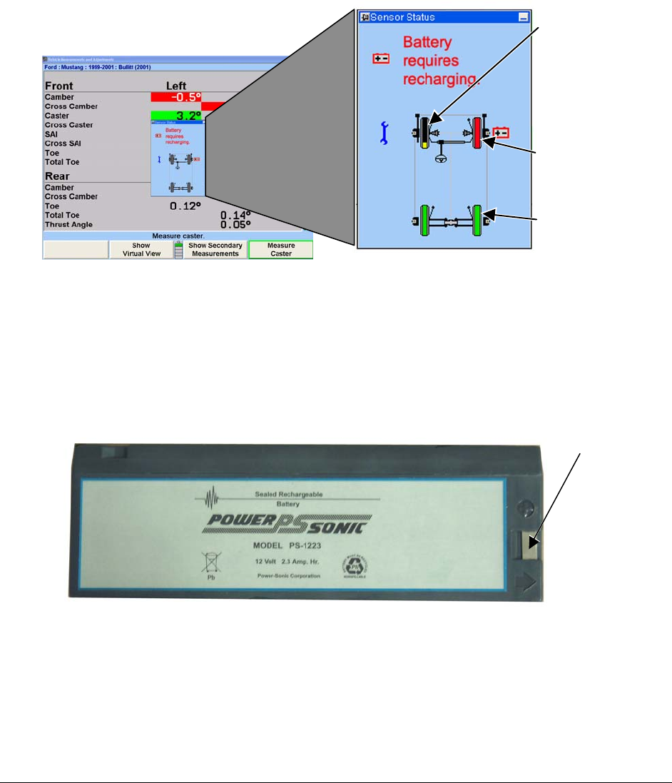
Any sensor that is powered up after being off for a while will initially indicate 100% capacity
on the aligner screen. This is not an accurate indication of the charge state of the battery.
The battery has a “surface charge” which dissipates quickly. Within 5 minutes of operation
the on-screen battery level indicator will settle at its true value. The individual wheels on the
screen indicate the actual battery condition and are color-coded. The following is an
indication of battery charging condition:
Green = fully charged or partially charged
Yellow = approximately 20% charge left
Red (with battery recharging icon) = requires charging
PARTIALLY
CHARGED BATTERY
GREEN-FULLY
CHARGED BATTERY
A RED INDICATION AND
THE RECHARGING ICON
INDICATING BATTERY
REQUIRES CHARGING
The charging circuit has been “fine tuned” to work specifically with Hunter batteries, part
number 194-23-2 (Powersonic part number PS-1223). Substituting different batteries is not
recommended.
A sensor that is being used, and has a low battery, can retain its measurement data if a “hot
swap” battery replacement is made. Hot swapping the battery requires that the user replaces
the battery, and then tilts the sensor completely forward, then completely backward. The
sensor settings will be restored and the alignment can proceed.
TERMINAL
Battery – Hunter 194-23-2 (Powersonic PS-1233)
DSP500 Series Wheel Alignment Sensors 1. Getting Started • 7
1.6 Vehicle Preparation
Drive the vehicle onto the alignment lift/rack until the front wheels are centered on the
turnplates.
Install wheel chocks to prevent the vehicle from rolling.
Raise the front and rear axles off the lift/rack. If your lift/rack does not have front and rear
axle jacks, raise the axle on which you will be performing the alignment.
Lower the lift/rack leveling legs if your lift/rack is so equipped, and then lower the lift/rack
onto the legs. If your lift/rack does not have leveling legs, lower the lift/rack onto the
lift/rack locks.
Check and adjust the tire pressure, inspect for unevenly worn or mismatched tires.
Inspect all suspension and steering linkage components for wear or damage. A thorough
inspection is important.
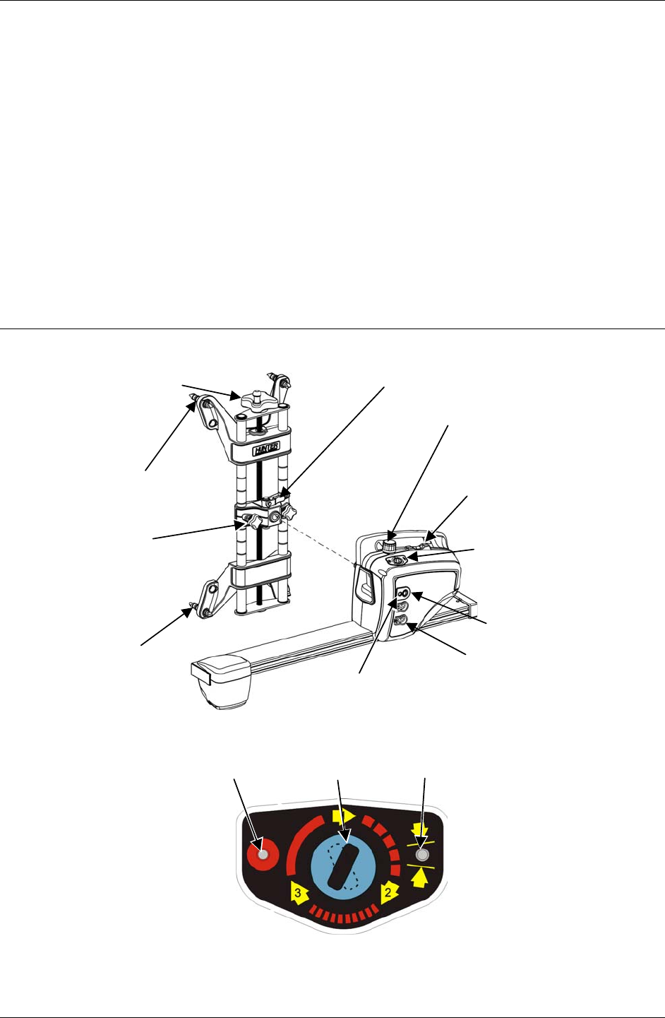
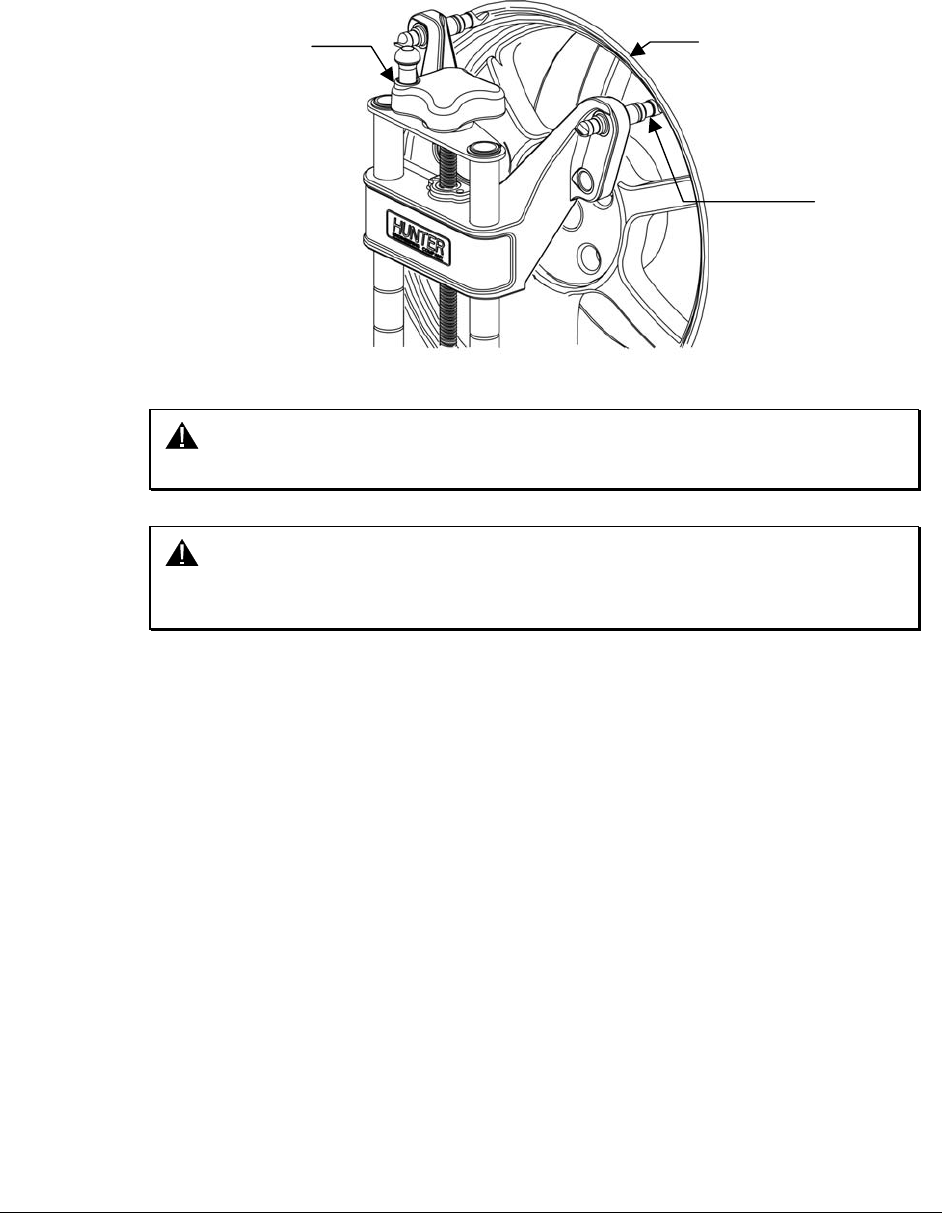
1.7 Equipment Components and Controls
WHEEL ADAPTOR
ADJUSTMENT KNOB
RIM STUDS
SENSOR LOCKING
LEVER
CENTER
CASTING
LOCK KNOBS SENSOR CONTROLS
SENSOR OR
TURNPLATE
CABLE
CONNECTORS
SWITCH
SENSOR LOCKING KNOB
CHARGE INDICATOR
SENSOR AND WHEEL ADAPTOR
RIM STUDS
LEVEL
SENSOR CONTROLS
DSP506/DSP508
RED LED
COMPENSATE
INDICATOR
GREEN LED
POSITION
INDICATOR
COMPENSATION
BUTTON
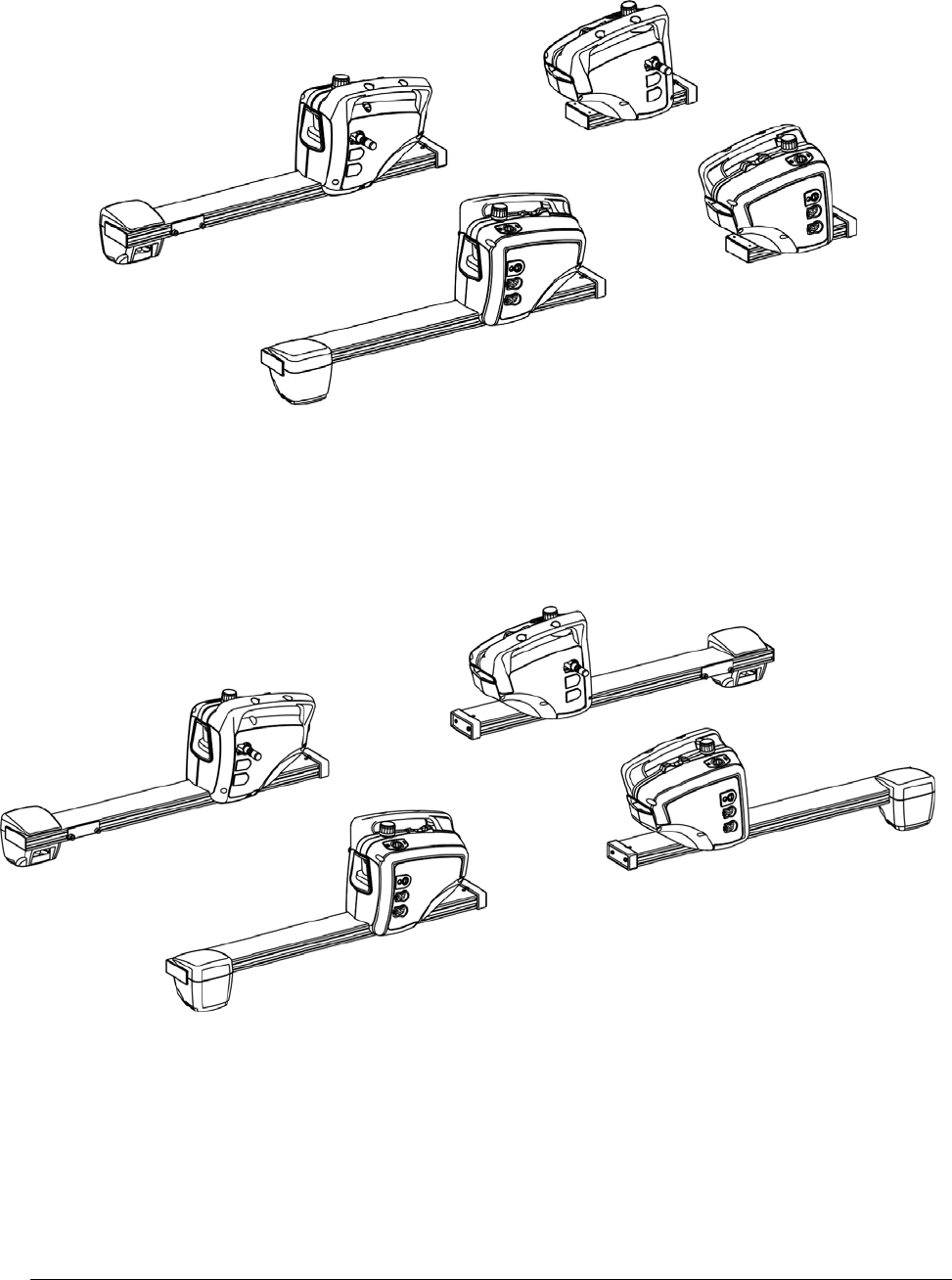
8 • 1. Getting Started DSP500 Series Wheel Alignment Sensors
FRONT SENSORS
REAR SENSORS
DSP506/506-XF SENSORS
FRONT SENSORS
REAR SENSORS
DSP508/508-XF SENSORS
DSP500 Series Wheel Alignment Sensors 2. Mounting Sensors • 9
2. MOUNTING SENSORS
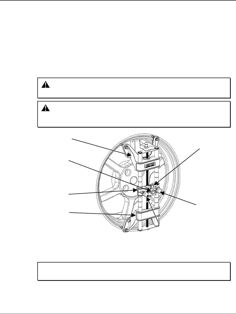
2.1 Mounting Sensors Onto Wheel Adaptors
Sensors may be mounted on the wheel adaptors before mounting the wheel adaptors on
the vehicle. In some cases, it may be easier to mount the wheel adaptor first and then
mount the sensor onto the adaptor. Either method may be used.
Center the wheel adaptor center casting between the upper and lower castings. When
the center casting is properly centered, a plunger ball will fall into the detent position on
the adaptor rod.
Tighten both center casting lock knobs firmly. This will prevent the center casting from
slipping down when the sensor is attached.
CAUTION: Hand tighten center casting lock knobs as tight as possible (DO
NOT USE TOOLS TO TIGHTEN).
CAUTION: If the center casting lock knobs are not firmly tightened, runout
compensation and alignment accuracy will be adversely
affected.
CENTER CASTING
CENTER
CASTING LOCK
KNOB
UPPER CASTING
LOWER CASTING
SENSOR SHAFT
MOUNTING HOLE
ADAPTOR
LOCKING
LEVER
CENTER
CASTING LOCK
KNOB
If detached, attach the sensor to the wheel adaptor by inserting the sensor mounting
shaft (at the rear of the sensor) into the sensor mounting hole in the middle of the center
casting.
NOTE: The sensor shaft must be fully inserted into the sensor shaft
mounting hole.
10 • 2. Mounting Sensors DSP500 Series Wheel Alignment Sensors
Wheel Adaptor 175-285-1
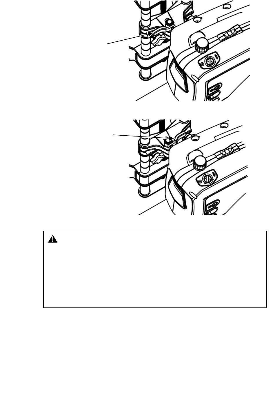
ADAPTOR LEVER
UNLOCKED
POSITION
Rotate the adaptor locking lever clockwise to the locked position.
LOCKED
POSITION
ADAPTOR LEVER
CAUTION: When mounting sensors to the wheel adaptors, the sensor shaft
must be fully seated. Make certain that there is no play or
looseness between the sensor shaft and the wheel adaptor.
Rotate the wheel while holding the sensor. Listen and feel for
movement between the sensor and wheel adaptor. Runout
compensation and alignment accuracy will be adversely affected
if there is any movement between the sensor and wheel adaptor.
Sensors must fit tightly against the surface of the wheel adaptor
or the lock may not hold. This could allow the sensor to fall and
be damaged.
When the sensor is mounted, the sensor locking lever should be rotated using firm hand
pressure. Tools should not be used to force the locking lever. If the lever can be rotated
until it contacts the casting and is not fully locked, refer to “Adjusting Wheel Adaptor Lock
Lever” on page 23.
DSP500 Series Wheel Alignment Sensors 2. Mounting Sensors • 11
Wheel Adaptor 175-321-1 with Ratchet Adaptor Locking Lever
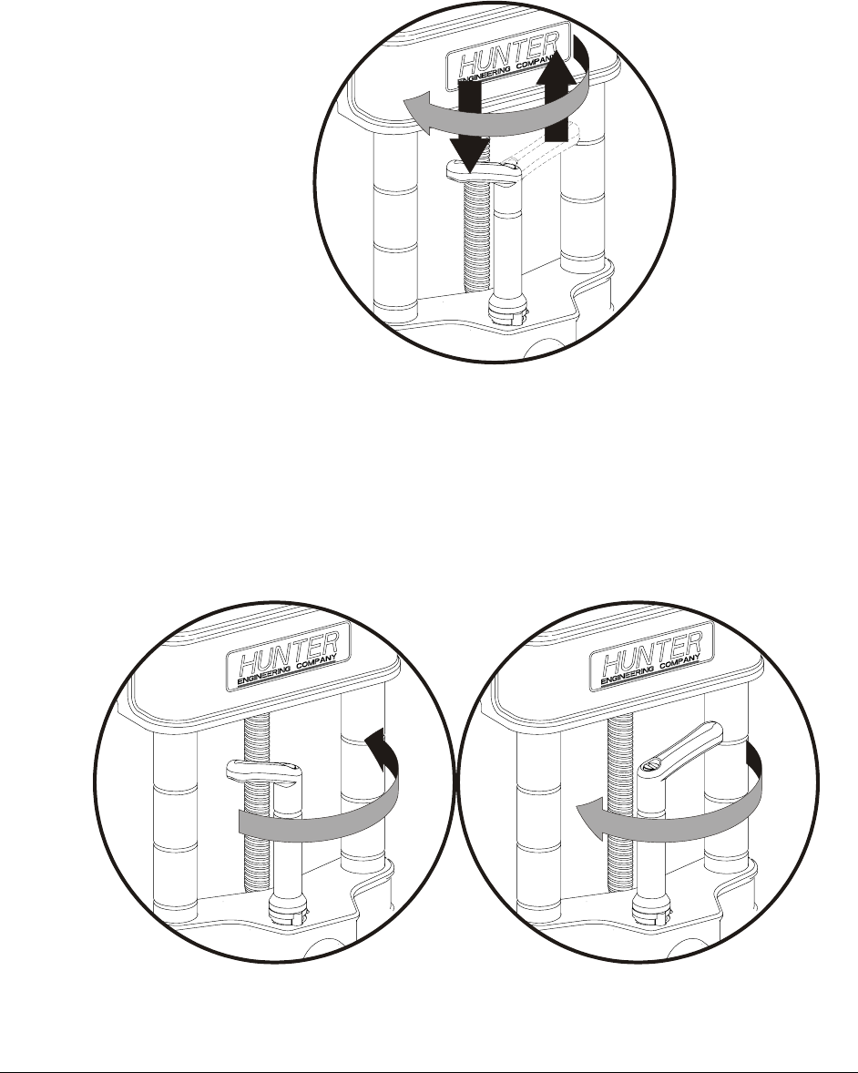
Rotate locking lever clockwise to tighten. If upper casting prevents rotation of lever,
either expand adaptor to move upper casting or re-position the lever by lifting lever up to
disengage, rotating counter-clockwise, and lowering to re-engage.
Proceed until the shaft is locked tight to adaptor.
With shaft fully locked, re-position the lever to the 9 o’clock position by lifting lever up to
disengage, rotating to 9 o’clock, and lowering to re-engage.
Re-position lever to 9 o’clock
The lever in the 9 o’clock position eliminates possible contact with upper casting or
sensor during alignments.
Operation of Ratchet Adaptor Locking Lever after Initial Setup
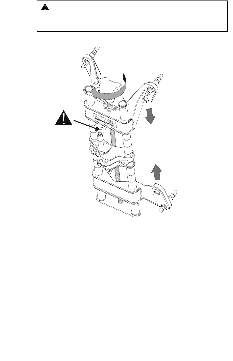
To remove the sensor or reposition a target, loosen the lock by turning the lever counter-
clockwise to the 3 o’clock position.
To loosen, turn lever from 9 to 3 o’clock To lock, turn lever from 3 to 9 o’clock
To lock the sensor or target, tighten the lock by turning the lever clockwise to 9 o’clock
position.
12 • 2. Mounting Sensors DSP500 Series Wheel Alignment Sensors
CAUTION: Failure to follow tightening and loosening procedures may result
in damage to lever. Upper casting can damage lever if contact
occurs when going for a large to small diameter rim. Refer to
figure below.
LOWERING THE
UPPER CASTING
CAN DAMAGE
THE LEVER
WHEN LOCATED
IN THE WRONG
POSITION
DSP500 Series Wheel Alignment Sensors 2. Mounting Sensors • 13
2.2 Mounting Wheel Adaptors Onto Wheels
Wheels With No Rim Lip (Attaching To Outer Rim Lip)
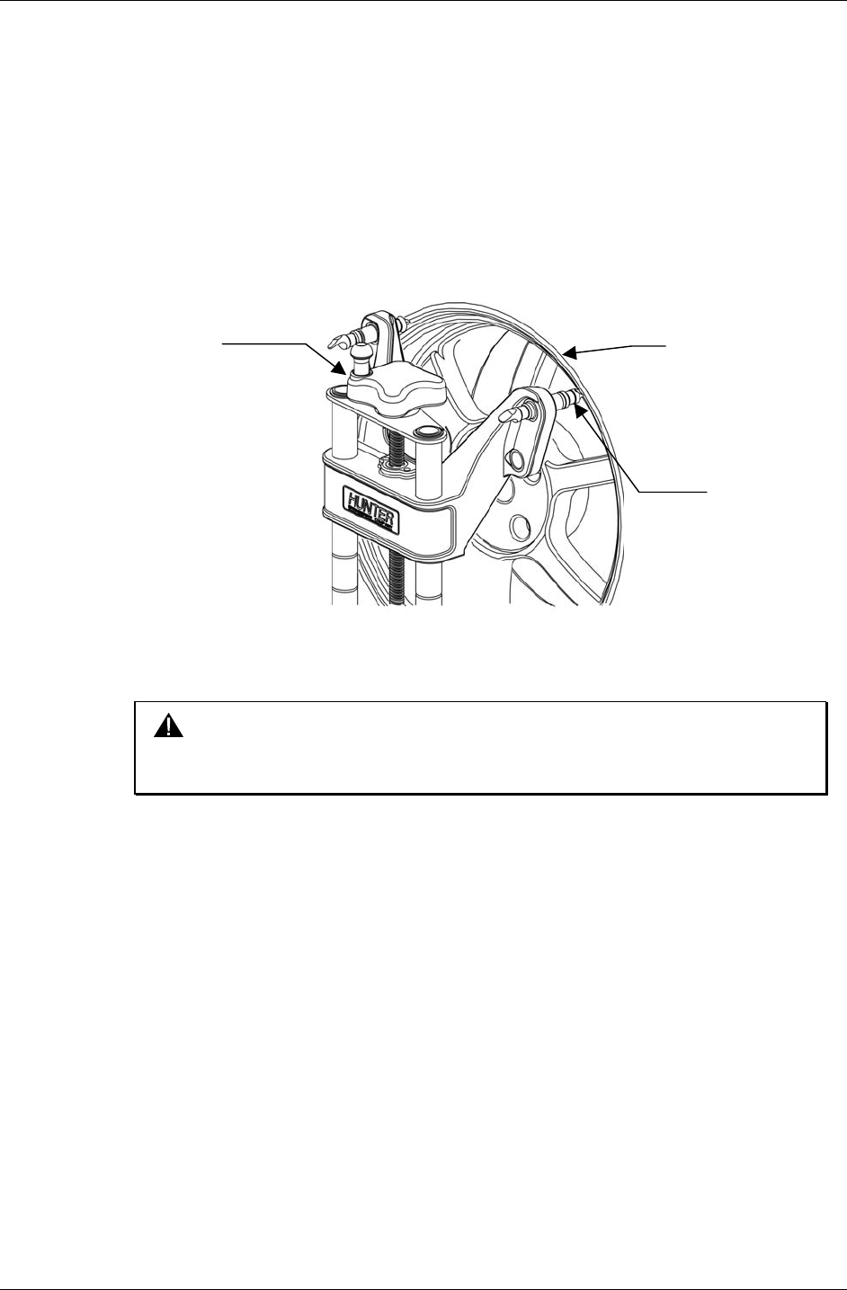
Position the wheel adaptor with the two upper external rim studs on the outside of the
wheel rim.
Align the two lower external rim studs on the outside of the wheel rim and check that all
four rim studs will engage the outside of the wheel rim.
Turn the adaptor adjustment knob to firmly attach the adaptor to the wheel.
ADAPTOR
ADJUSTMENT
KNOB WHEEL RIM
SPADE SLEEVE
Test the security of the installation by lightly tugging on the wheel adaptor.
CAUTION: Do not allow the rim studs to slip on the wheel. Runout
compensation and alignment accuracy will be adversely affected
if the wheel adaptor is allowed to slip on the wheel.
14 • 2. Mounting Sensors DSP500 Series Wheel Alignment Sensors
Wheels With Rim Lip (Attaching To Inner Rim Lip)
Position the wheel adaptor with the two lower rim studs engaging the lower wheel rim lip.
Align the two upper rim studs with the upper wheel rim lip and check that all four studs
will engage the inner portion of the rim lip.
Turn the adaptor adjustment knob to firmly attach the adaptor to the wheel.
ADAPTOR
ADJUSTMENT
KNOB
WHEEL RIM
RIM STUD
Test the security of the installation by tugging on the wheel adaptor.
CAUTION: Do not use rim studs on alloy or clear coat wheels. Rim studs
can damage these wheels.
CAUTION: Do not allow the rim studs to slip on the wheel. Runout
compensation and alignment accuracy will be adversely affected
if the wheel adaptor is allowed to slip on the wheel.
DSP500 Series Wheel Alignment Sensors 2. Mounting Sensors • 15
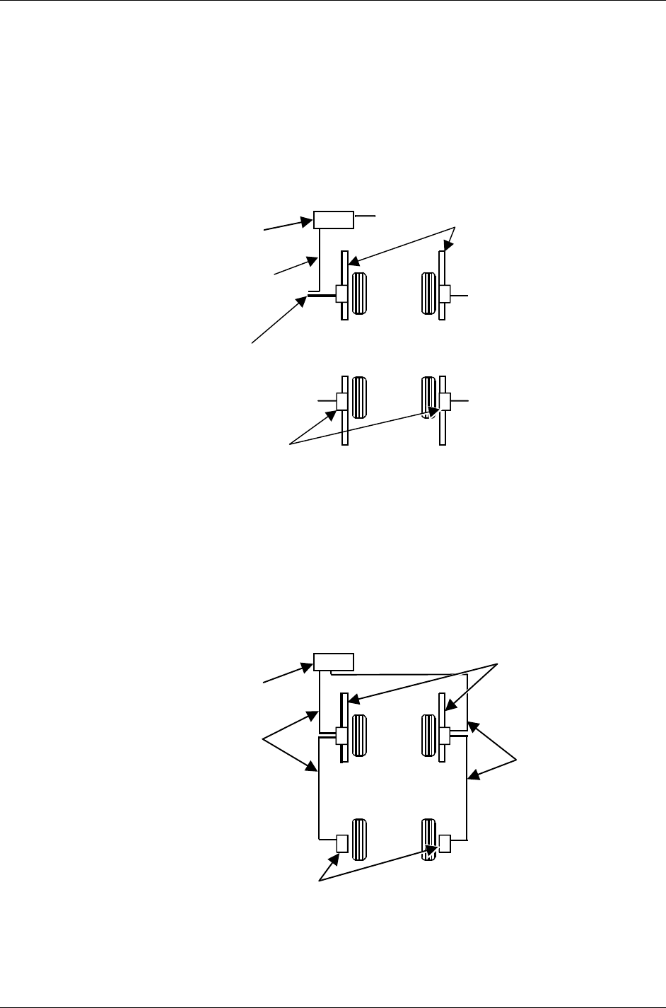
2.3 Connecting Sensor Cables
Connecting Sensor Cables With Optional Rack Wiring Kit
Connect each sensor to a rack wiring box with short sensor cables (either connector may
be used).
Connect a front rack wiring box to the console with a long sensor cable (any available
connector may be used).
SENSOR
CABLE
TO CONSOLE
REAR SENSOR
CONSOLE
TO RACK
BOX
TO RACK BOX
TO RACK BOX
FRONT SENSOR
TO RACK BOX
Connecting Sensor Cables Without Optional Rack Wiring Kit
Connect the two rear sensors to the front sensors using sensor cables (either front
sensor connector may be used).
Connect the two front sensors to the console using sensor cables (any available console
cable socket may be used).
REAR SENSOR
CONSOLE
FRONT
SENSOR
SENSOR
CABLE
SENSOR
CABLE

16 • 2. Mounting Sensors DSP500 Series Wheel Alignment Sensors

DSP500 Series Wheel Alignment Sensors 3. Compensating Sensors • 17
3. COMPENSATING SENSORS
3.1 General Compensation
The sensors must be compensated to eliminate errors in angle measurements caused by
runout of the wheel, wheel adaptor, and sensor shaft.
The default setting for the alignment console can be set for either 2 or 3-point
compensation. However, the operator still has the option to override the default setting by
pressing the “2-Point” or “3-Point” Compensation softkey on the “Compensation Control”
screen on the aligner console.
The sensors must be “ON” to compensate.
If a previously compensated sensor should require re-compensation, pressing the sensor
compensate button twice within four seconds will retake the first reading for that sensor.
Do not disturb the sensor until the red LED responds.
Sensors may be compensated in any order; however, these precautions must be followed:
If a sensor is removed from a wheel, that sensor must be re-compensated when
reinstalled. The other sensors do not need re-compensation.
During 2-point compensation and normal operation, be certain no obstructions are
blocking the infrared beams between the sensors. Should a blockage occur, the
affected sensor(s) shown in the illustration on the CRT will flash on and off and the
displayed toe measurement of the sensor(s) will go blank until the obstruction is
cleared.
When compensating sensors that are mounted to the vehicle drive wheels, place
the transmission in NEUTRAL.
The lift/rack should be level on the leveling legs.
3.2 3-Point Compensation
All sensors need not be mounted before starting compensation. The sensors may be
mounted and compensated individually, or compensation may be performed on 1, 2, 3, or all
4 sensors at once.
Raise either the front or rear axles, or both, while remembering to use the safety on all
jacks.
WARNING: If only one axle is raised, chock wheels on the axle that is
not being raised during compensation, to prevent the
vehicle from rolling.
Turn sensors on if necessary and select any one of the sensors for compensation. The
starting position of the wheel adaptor does not matter. The green LED will be on.

18 • 3. Compensating Sensors DSP500 Series Wheel Alignment Sensors
RED LED
COMPENSATE
INDICATOR
GREEN LED
POSITION
INDICATOR
COMPENSATION
BUTTON
Hand-tighten the sensor lock knob.
Rotate the wheel until the sensor is level (as indicated by the spirit level on top of the sensor).
Press the compensate button. Do not disturb the sensor until one red LED begins to blink
and the green LED turns off, indicating that the measurements have been stored.
Loosen the sensor lock knob and rotate the wheel 120°, left or right, until the green LED
turns on. Hand tighten the sensor lock knob and rotate the wheel to level the sensor.
NOTE: It is recommended that the front wheels of front wheel drive
vehicles be rotated in the forward direction to keep from
disturbing the sensor on the opposite front wheel.
With the green compensate LED on, press the compensate button. Do not disturb the
sensor until the red LED begins to blink faster and the green compensate LED turns off
to indicate that the measurements have been stored.
Loosen the sensor lock knob and rotate the wheel 120° more, until the green LED turns
on. Hand tighten the sensor lock knob and rotate the wheel to level the sensor.
With the green LED on, press the compensate button. Do not disturb the sensor. Wait for
the sensor to save the measurement. The red LED and the green LED will stay on.
Loosen the sensor lock knob.
The sensor is now compensated. Repeat this procedure for the remaining sensor(s).
NOTE: All sensors should be level, but unlocked, with cables hanging
straight down (if being used) to minimize tilt of the sensors.
Avoid rapid steering motion that may cause sensors to swing
vertically, which can cause them to come into contact with the
rack, or even dislodge from the wheel.
Remove the lock pins from the turning angle gauges and rear slip plates.
Apply the parking brake and place the transmission in park if applicable.
Lower the vehicle onto the turning angle gauges.
Jounce the vehicle.
3-Point compensation is complete. The green LED and red LED on each sensor will be
on.
After 3-point compensation, the wheel may be rotated to any position without affecting
the alignment measurements.
Continue the alignment procedure.

DSP500 Series Wheel Alignment Sensors 3. Compensating Sensors • 19
3.3 2-Point Compensation
NOTE: To compensate the sensors, both the front and rear sensor on
that side of the vehicle must be mounted, and the longitudinal
toe beam must not be obstructed. Do not rotate one wheel while
the measurements are being saved at the other. The preferred
method is to compensate the sensors separately.
Raise either the front or rear wheels of vehicle.
WARNING: Chock wheels on axle that is not being raised during
compensation to prevent vehicle rolling.
Loosen the sensor lock knobs of all the sensors.
Select any one of the sensors for compensation. The green LED will be on.
Rotate the wheel adaptor to any desired position. Compensation should preferably begin
(and end) with the wheel adaptor in the vertical position to provide a visual indication that
the vehicle wheel has not rotated.
Snug down the sensor lock knob.
Rotate the wheel until the sensor is level (as indicated by the level on top of the sensor).
Press the compensate button. Do not disturb the sensor until the red LED begins to flash
and the green LED turns off indicating that the measurement has been saved.
Loosen the sensor lock knob.
Rotate the wheel clockwise 180° until the green LED comes on. When the green LED is
on, snug down the sensor lock knob and rotate the wheel to level the sensor.
Press the compensate button. Do not disturb the sensor. Wait for the sensor to save the
measurement. The red LED and green LED will stay on, indicating that the measurement
has been saved and compensation is complete.
Loosen the sensor lock knob.
The sensor is now compensated. Repeat this procedure for the remaining sensor(s).
When using the 2-point compensation method, the wheel adaptor must remain in the
same rotational position as it was when its compensation was completed. The green LED
will be on when the wheel is rotated to the correct position.
NOTE: All sensors should be level, but unlocked (unless directed to
level and lock sensors during the WinAlign operation sequence),
with cables hanging straight down to minimize tilt of the sensors
during caster measurement turn. If sensors are not locked, then
avoid rapid steering motion that may cause sensors to swing
vertically, which can cause them to come into contact with the
rack, or even dislodge from the wheel.
Remove the lock pins from the turning angle gauges and rear slip plates.
Apply the vehicle parking brake and place the transmission in park.
Lower the vehicle onto the turning angle gauges.
Jounce the vehicle.
2-Point compensation is complete. The green LED and red LED on each sensor will be
on.
Continue the alignment procedure.
20 • 3. Compensating Sensors DSP500 Series Wheel Alignment Sensors
3.4 Rolling Compensation
NOTE: This procedure can be performed using the 3-point or 2-point
compensation method.
CAUTION: This procedure should be performed only on a pit-installed rack,
and should not be performed on a lift or above-ground rack. The
vehicle could roll off the lift/rack, causing severe personal injury
and damage to the vehicle, or rack.
From the “Control Compensation” popup screen, press “Use Rolling Compensation.” The
“Rolling Compensation” popup screen will appear.
3-Point Procedure
Position the vehicle so that it can be rolled forward, with the wheels able to rotate 240°.
Level and lock the sensors, then press “Ready.” When the sensors are stable, the
measurements will be saved.
NOTE: Beginning the rolling compensation procedure removes any old
compensation from the sensors.
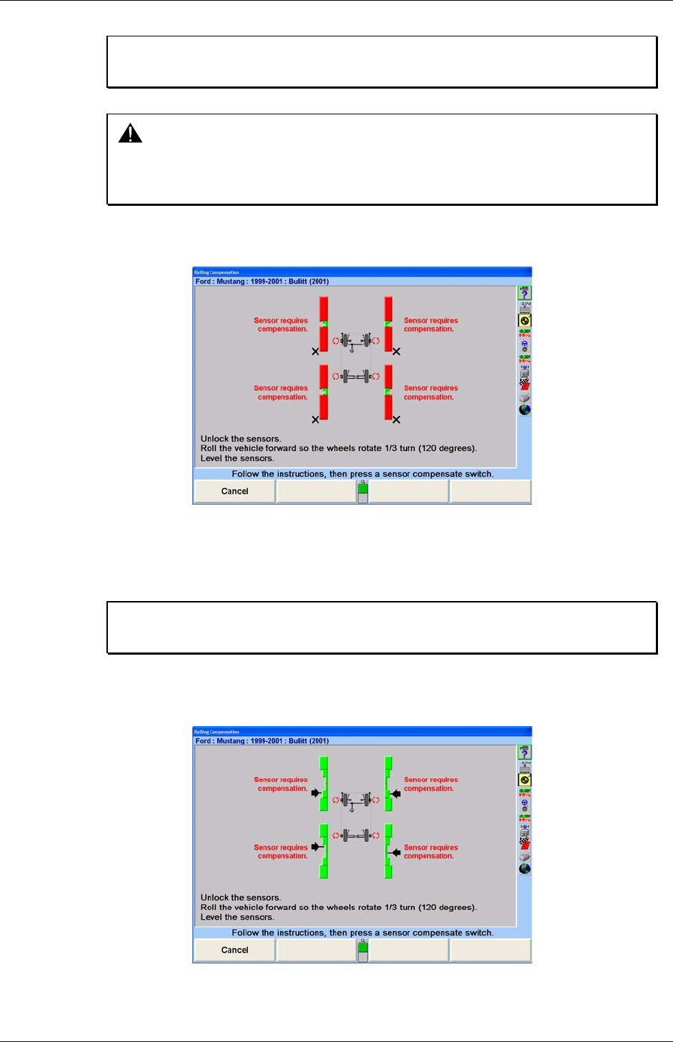
The screen instructs you to roll the vehicle forward so the wheels rotate 120°. Vertical bar
graphs show when this is correct. Unlock the sensors and roll the vehicle forward until
the arrows are in the null position.
Level and lock the sensors. The green LED must be on at each sensor.
DSP500 Series Wheel Alignment Sensors 3. Compensating Sensors • 21
Press and release the compensate switch on any ONE sensor. When the sensors are all
stable, the measurements will be saved.
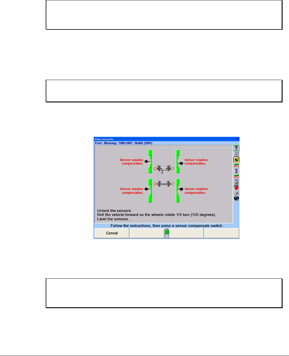
The screen instructs you to roll the vehicle forward so the wheels rotate another 120°.
Vertical bar graphs show when this is correct. Unlock the sensors and roll the vehicle
forward until the arrows are in the null position.
Level and lock the sensors. The green LED must be on at each sensor.
Press and release the compensate switch on any ONE sensor. When the sensors are all
stable, the measurements will be saved. The “Rolling Compensation” popup screen will
close.
NOTE: The 3-point rolling compensation procedure need not end with
the vehicle in the proper position to adjust the alignment. The
wheels are allowed to rotate after the procedure is performed.
2-Point Procedure
Position the vehicle so that it can be rolled forward, with the wheels able to rotate 180°.
Level and lock the sensors, then press “Ready.” When the sensors are stable, the
measurements will be saved.
NOTE: Beginning the rolling compensation procedure removes any old
compensation from the sensors.
The screen instructs you to roll the vehicle forward so the wheels rotate 180°. Vertical bar
graphs show when this is correct. Unlock the sensors and roll the vehicle forward until
the arrows are in the null position.
Level and lock the sensors. The green LED must be on at each sensor.
Press and release the compensate switch on any ONE sensor. When the sensors are all
stable, the measurements will be saved. The “Rolling Compensation” popup screen will
close.
NOTE: The 2-point rolling compensation procedure MUST end with the
vehicle in the proper position to adjust the alignment. The wheels
are NOT allowed to rotate after the procedure is performed.

22 • 3. Compensating Sensors DSP500 Series Wheel Alignment Sensors
Procedure Limitations
CAUTION: This procedure must be performed carefully, or inaccurate
alignment measurements will result. The axles must always
“point” exactly the same direction as the vehicle rolls during the
procedure. A change in the pointing direction of an axle during
the procedure will be interpreted by the system as runout.
1. Do not allow the front wheels to change their “steering” direction
as the vehicle is rolled.
2. Do not perform the procedure on a bumpy or uneven surface.
3. Do not perform the procedure on a vehicle that has uneven or
out-of-round tires.
4. Do not push or pull the vehicle by the tires or wheels during the
procedure.
5. Push the vehicle only forward during the procedure. Do not push
the vehicle forward, then backward.
6. Do not use the brakes during the procedure.
3.5 Compensation Recall Mode
If sensor power is temporarily interrupted after compensation, a short-term backup
memory on the sensor may hold compensation values until power is restored. When
power is restored, the sensor will indicate that it has valid compensation values by
illuminating the green compensation indicator while flashing the red compensation
indicator. If the sensor has not been dismounted from the vehicle wheel, the
compensation procedure does not have to be repeated. Compensation can be restored
by unlocking the lock knob and tilting the sensor in either direction until the red indicator
stops flashing and stays on. Afterwards, restore the sensor to its original position. If re-
compensation is required, pressing the compensation button twice within four seconds
will retake the first reading for that sensor. Refer to the compensation section for
complete compensation procedure.
DSP500 Series Wheel Alignment Sensors 4. Operation Information • 23
4. OPERATION INFORMATION
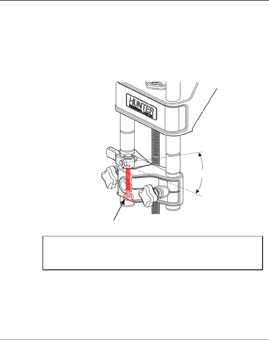
4.1 Adjusting Wheel Adaptor 175-285-1 Lock Lever
The wheel adaptor lock lever should not contact the wheel adaptor center casting before
the sensor shaft is tightly secured. An adjustment can be made to the lock lever
assembly to restore its full tightening capability.
Turn the adjusting thumbscrew to adjust the lock lever adjustment screw as illustrated
below (do not remove the assembly). With the sensor fully seated in the adaptor and firm
hand force applied to the lock lever, adjust the lock lever screw from the bottom side of
the center casting so the lever will stop approximately 30° short of contacting the center
casting.
3 mm
HEX KEY
33
0
NOTE: Normal manufacturing variations will allow the clearance
between the lever and casting to change if different sensors are
mounted to a given adaptor. This variation is acceptable if the
lever has enough travel to fully tighten the lock onto the shaft.

24 • 4. Operation Information DSP500 Series Wheel Alignment Sensors
4.2 Sensor Level Check Procedure
To achieve an accurate alignment, it is important that the sensors hang level when the
sensor lock knob is loosened. A sensor must be balanced correctly to hang level.
To check the balance of a sensor:
Mount the sensor on a wheel adaptor.
Mount the wheel adaptor onto a wheel without connecting the sensor cable.
With the sensor lock knob loosened, wait until the sensor does not rock on
the wheel adaptor.
Observe the level in the sensor.
If the bubble is in the center of the level, as shown below, the sensor is
balanced.
NOTE: A level reminder icon will appear on the vehicle plan view
indicator when a sensor is severely out of level.
BUBBLE
If the bubble is off to one side of the level, as shown below, the sensor must
be adjusted to restore the sensor to level.
BUBBLE
To balance sensors, loosen the screws securing the weight to the toe arm. Slide the
weight in the proper direction to center the bubble in the level.
LOOSEN
SLIDE
Contact your local Hunter Service Representative if you need assistance with
balancing adjustments.
DSP500 Series Wheel Alignment Sensors 4. Operation Information • 25
4.3 Ride Height Measurement (Optional)
When equipped with the ride height option, the DSP500 Series Sensors will take
accurate ride height (RH) measurements using a ride height tool and compare them to
the stored specifications. The CRT must be displaying the "Ride Height" screen to
measure ride height. The ride height procedure can be accessed from the primary screen
labeled “Make Additional Adjustments.”
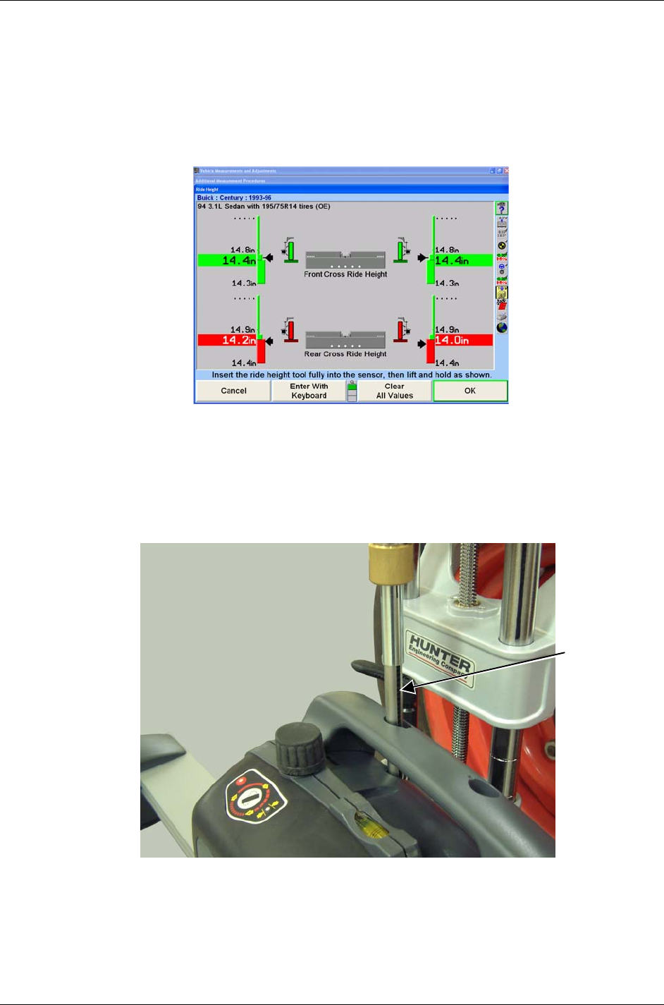
From the “Additional Measurements Procedures” screen, select “Ride Height” and press
“OK.” The following “Ride Height” screen will appear as shown below.
Lower the vehicle’s axles if they are raised, and then jounce the vehicle.
Level and lock the sensor on the wheel to be measured.
Insert the end of the ride height tool into the sensor with the groove in the rod facing the
rear of the sensor as shown below. It may be necessary to slightly rotate the rod of the
ride height tool in the sensor so the groove in the rod engages the key in the sensor.
Lower the tool until its shoulder bottoms out on the sensor.
GROOVE
26 • 4. Operation Information DSP500 Series Wheel Alignment Sensors
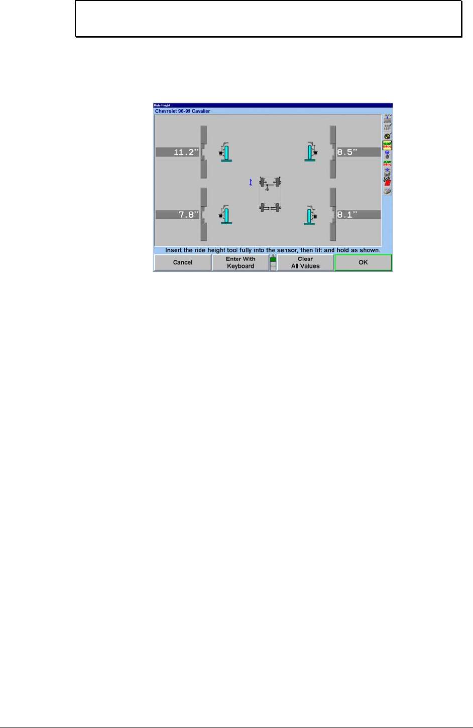
NOTE: Failure to fully seat the ride height tool shoulder on the sensor
will cause inaccurate RH measurements.
Raise the RH tool until the horizontal arm touches the underside of the wheel arch above
the center of the wheel.
Hold the RH tool in that position until the console indicates a reading has been taken.
Remove the RH tool and repeat this procedure with the other sensors.
DSP500 Series Wheel Alignment Sensors 5. Maintenance • 27
5. MAINTENANCE
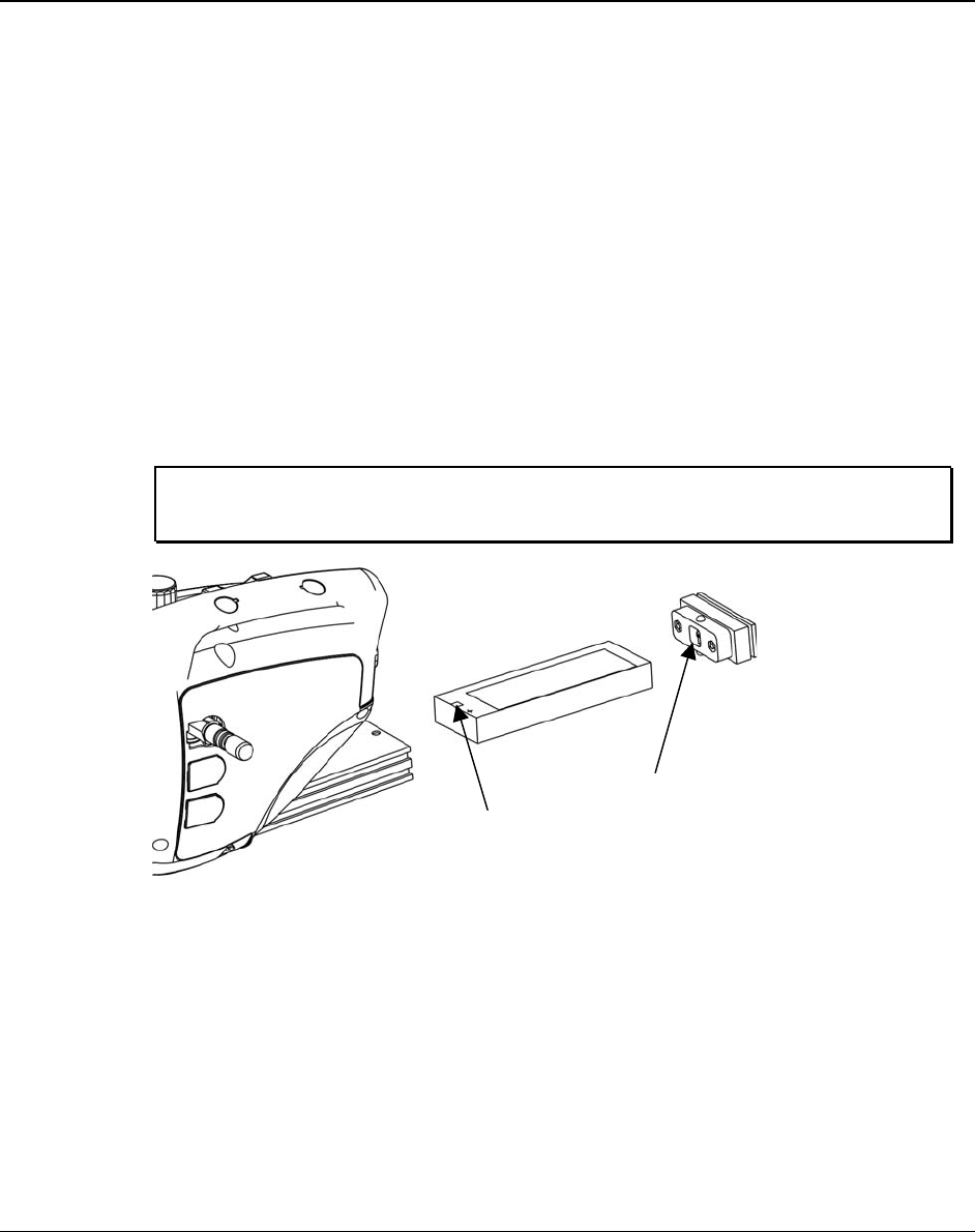
5.1 DSP506XF and DSP508XF Battery Replacement Instructions
This procedure provides instructions for replacing the lead acid battery in
DSP506XF and DSP508XF wireless sensors.
Remove the battery as follows:
1. Depress the upper and lower release buttons on the battery cover and
remove.
2. Tilt sensor back and remove battery.
Replace the battery as follows:
1. Insert the battery with the positive terminal on top.
2. Replace the battery cover.
NOTE: The sensors are designed to power-up when the battery is
replaced.
BATTERY CAP
POSITIVE
BATTERY
TERMINAL

28 • 5. Maintenance DSP500 Series Wheel Alignment Sensors
5.2 DSP506XF and DSP508XF Hot Swap Battery Replacement
Instructions
This procedure provides instructions for hot swapping the lead acid battery in
DSP506XF and DSP508XF wireless sensors during an alignment procedure. Hot swapping
the battery will recall/retain the information in the sensor if the alignment procedure is still in
progress.
If the sensor was compensated prior to swapping the battery, the sensor will indicate it by
illuminating the green compensation indicator while flashing the red compensation indicator.
1. Remove and replace the battery as described above.
2. After unit has powered up, unlock the lock knob and tilt the sensor in either
direction until the red indicator stops flashing and stays on. Do not remove the
sensor or wheel adaptor from the wheel.
3. Restore the sensor to its original position.

DSP500 Series Wheel Alignment Sensors 5. Maintenance • 29

30 • 5. Maintenance DSP500 Series Wheel Alignment Sensors

DSP500 Series Wheel Alignment Sensors 5. Maintenance • 31