Hunter Fan Indoor Ceiling Users Manual 41801 01
Indoor Ceiling Fan to the manual 6a894b83-06f2-44a2-a656-2de870443d71
2015-01-24
: Hunter-Fan Hunter-Fan-Indoor-Ceiling-Fan-Users-Manual-340814 hunter-fan-indoor-ceiling-fan-users-manual-340814 hunter-fan pdf
Open the PDF directly: View PDF ![]() .
.
Page Count: 11

© 2003 Hunter Fan Company 41814-01 01/14/2003
11
11
1
41814-01 01/14/2003 © 2003 Hunter Fan Company
22
22
2
Your new Hunter® ceiling fan is an addition to your home or office
that will provide comfort and performance for many years. This
installation and operation manual gives you complete instructions
for installing and operating your fan.
We are proud of our work. We appreciate the opportunity to sup-
ply you with the best ceiling fan available anywhere in the world.
Before installing your fan, record the following information for your
records and warranty assistance. Please refer to the carton and the
Hunter nameplate label (located on the top of the fan motor hous-
ing) for the proper information.
Model Name: __________________________
Catalog/Model No.: ______________
Serial No.: _____________________
Date Purchased: ___ / ___ / ______
Where Purchased: _______________________________
Please also attach your receipt or a copy of your receipt for refer-
ence.
cautions and warnings
••
••
•RR
RR
Ree
ee
eaa
aa
ad ed e
d ed e
d enn
nn
ntt
tt
tirir
irir
ire be b
e be b
e boo
oo
ooo
oo
okk
kk
kll
ll
lee
ee
et ct c
t ct c
t caa
aa
arr
rr
ree
ee
eff
ff
fullull
ullull
ully by b
y by b
y bee
ee
eff
ff
foo
oo
orr
rr
re be b
e be b
e bee
ee
egg
gg
ginninn
inninn
inninin
inin
ing ing in
g ing in
g inss
ss
stt
tt
taa
aa
al-l-
l-l-
l-
ll
ll
laa
aa
att
tt
tii
ii
ioo
oo
onn
nn
n. S. S
. S. S
. Saa
aa
avv
vv
ve te t
e te t
e thh
hh
hee
ee
ess
ss
se ine in
e ine in
e inss
ss
stt
tt
trr
rr
ruu
uu
ucc
cc
ctt
tt
tii
ii
ioo
oo
onn
nn
nss
ss
s.....
••
••
•UsUs
UsUs
Use oe o
e oe o
e onlnl
nlnl
nly Hy H
y Hy H
y Hunun
unun
untt
tt
tee
ee
er rr r
r rr r
r ree
ee
epp
pp
pll
ll
laa
aa
acc
cc
cee
ee
emm
mm
mee
ee
enn
nn
nt pt p
t pt p
t paa
aa
arr
rr
rtt
tt
tss
ss
s.....
••
••
•TT
TT
To ro r
o ro r
o ree
ee
edudu
dudu
ducc
cc
ce te t
e te t
e thh
hh
he re r
e re r
e rii
ii
iss
ss
sk ok o
k ok o
k of pf p
f pf p
f pee
ee
err
rr
rss
ss
soo
oo
onn
nn
naa
aa
al inl in
l inl in
l injurjur
jurjur
juryy
yy
y, a, a
, a, a
, att
tt
ttt
tt
taa
aa
acc
cc
ch th t
h th t
h thh
hh
he fe f
e fe f
e faa
aa
ann
nn
n
dirdir
dirdir
diree
ee
ecc
cc
ctt
tt
tll
ll
ly ty t
y ty t
y to to t
o to t
o thh
hh
he se s
e se s
e supup
upup
uppp
pp
poo
oo
orr
rr
rt st s
t st s
t stt
tt
trr
rr
ruu
uu
ucc
cc
ctt
tt
turur
urur
ure oe o
e oe o
e of tf t
f tf t
f thh
hh
he be b
e be b
e builuil
uiluil
uildindin
dindin
ding ag a
g ag a
g acc
cc
c--
--
-
cc
cc
coo
oo
orr
rr
rdindin
dindin
ding tg t
g tg t
g to to t
o to t
o thh
hh
hee
ee
ess
ss
se ine in
e ine in
e inss
ss
stt
tt
trr
rr
ruu
uu
ucc
cc
ctt
tt
tii
ii
ioo
oo
onn
nn
nss
ss
s, a, a
, a, a
, ann
nn
nd ud u
d ud u
d uss
ss
se oe o
e oe o
e onlnl
nlnl
nly ty t
y ty t
y thh
hh
he he h
e he h
e haa
aa
arr
rr
rd-d-
d-d-
d-
ww
ww
waa
aa
arr
rr
re se s
e se s
e supup
upup
uppp
pp
plili
lili
liee
ee
ed.d.
d.d.
d.
••
••
•TT
TT
To ao a
o ao a
o avv
vv
voo
oo
oii
ii
id pd p
d pd p
d poo
oo
oss
ss
ssibsib
sibsib
sibll
ll
le ee e
e ee e
e ell
ll
lee
ee
ecc
cc
ctt
tt
trr
rr
rii
ii
icc
cc
caa
aa
al sl s
l sl s
l shh
hh
hoo
oo
occ
cc
ckk
kk
k, b, b
, b, b
, bee
ee
eff
ff
foo
oo
orr
rr
re ine in
e ine in
e inss
ss
stt
tt
taa
aa
allinllin
llinllin
llingg
gg
g
yy
yy
yoo
oo
our fur f
ur fur f
ur faa
aa
ann
nn
n, di, di
, di, di
, diss
ss
scc
cc
coo
oo
onnnn
nnnn
nnee
ee
ecc
cc
ct tt t
t tt t
t thh
hh
he pe p
e pe p
e poo
oo
oww
ww
wee
ee
er br b
r br b
r by ty t
y ty t
y turur
urur
urnn
nn
ninin
inin
ing og o
g og o
g off
ff
ff tf t
f tf t
f thh
hh
he ce c
e ce c
e cirir
irir
ir--
--
-
cc
cc
cuiui
uiui
uit bt b
t bt b
t brr
rr
ree
ee
eaa
aa
akk
kk
kee
ee
err
rr
rs ts t
s ts t
s to to t
o to t
o thh
hh
he oe o
e oe o
e ouu
uu
utt
tt
tll
ll
lee
ee
et bt b
t bt b
t boo
oo
ox ax a
x ax a
x ann
nn
nd ad a
d ad a
d ass
ss
sss
ss
soo
oo
occ
cc
cii
ii
iaa
aa
att
tt
tee
ee
ed wd w
d wd w
d waa
aa
allll
llll
ll
ss
ss
sww
ww
wii
ii
itt
tt
tcc
cc
ch lh l
h lh l
h loo
oo
occ
cc
caa
aa
att
tt
tii
ii
ioo
oo
onn
nn
n. I. I
. I. I
. If yf y
f yf y
f yoo
oo
ou cu c
u cu c
u caa
aa
annnn
nnnn
nnoo
oo
ot lt l
t lt l
t loo
oo
occ
cc
ck tk t
k tk t
k thh
hh
he ce c
e ce c
e cirir
irir
ircc
cc
cuiui
uiui
uit bt b
t bt b
t brr
rr
ree
ee
eaa
aa
akk
kk
k--
--
-
ee
ee
err
rr
rs in ts in t
s in ts in t
s in thh
hh
he oe o
e oe o
e off
ff
ff pf p
f pf p
f poo
oo
osisi
sisi
sitt
tt
tii
ii
ioo
oo
onn
nn
n, s, s
, s, s
, see
ee
ecc
cc
curur
urur
uree
ee
ell
ll
ly fy f
y fy f
y faa
aa
ass
ss
stt
tt
tee
ee
en a pn a p
n a pn a p
n a prr
rr
roo
oo
omm
mm
minin
inin
inee
ee
enn
nn
ntt
tt
t
ww
ww
waa
aa
arr
rr
rnn
nn
ninin
inin
ing dg d
g dg d
g dee
ee
evv
vv
vii
ii
icc
cc
cee
ee
e, s, s
, s, s
, suu
uu
ucc
cc
ch ah a
h ah a
h as a ts a t
s a ts a t
s a taa
aa
agg
gg
g, t, t
, t, t
, to to t
o to t
o thh
hh
he se s
e se s
e see
ee
err
rr
rvv
vv
vii
ii
icc
cc
ce pe p
e pe p
e paa
aa
ann
nn
nee
ee
el.l.
l.l.
l.
••
••
•AA
AA
All wll w
ll wll w
ll wirir
irir
irinin
inin
ing mug mu
g mug mu
g muss
ss
st bt b
t bt b
t be in ae in a
e in ae in a
e in acc
cc
ccc
cc
coo
oo
orr
rr
rdd
dd
daa
aa
ann
nn
ncc
cc
ce we w
e we w
e wii
ii
itt
tt
th nh n
h nh n
h naa
aa
att
tt
tii
ii
ioo
oo
onn
nn
naa
aa
al al a
l al a
l ann
nn
ndd
dd
d
ll
ll
loo
oo
occ
cc
caa
aa
al el e
l el e
l ell
ll
lee
ee
ecc
cc
ctt
tt
trr
rr
rii
ii
icc
cc
caa
aa
al cl c
l cl c
l coo
oo
odd
dd
dee
ee
es as a
s as a
s ann
nn
nd Ad A
d Ad A
d ANN
NN
NSS
SS
SI/NI/N
I/NI/N
I/NFF
FF
FPP
PP
PA 70. IA 70. I
A 70. IA 70. I
A 70. If yf y
f yf y
f yoo
oo
ou au a
u au a
u arr
rr
ree
ee
e
unun
unun
unff
ff
faa
aa
amm
mm
miliili
iliili
iliaa
aa
ar wr w
r wr w
r wii
ii
itt
tt
th wh w
h wh w
h wirir
irir
irinin
inin
ingg
gg
g, y, y
, y, y
, yoo
oo
ou su s
u su s
u shh
hh
hoo
oo
oulul
ulul
uld ud u
d ud u
d uss
ss
se a qe a q
e a qe a q
e a quu
uu
uaa
aa
alili
lili
liff
ff
fii
ii
iee
ee
ed ed e
d ed e
d ell
ll
lee
ee
ecc
cc
c--
--
-
tt
tt
trr
rr
rii
ii
icc
cc
cii
ii
iaa
aa
ann
nn
n.....
••
••
•TT
TT
To ro r
o ro r
o ree
ee
edudu
dudu
ducc
cc
ce te t
e te t
e thh
hh
he re r
e re r
e rii
ii
iss
ss
sk ok o
k ok o
k of pf p
f pf p
f pee
ee
err
rr
rss
ss
soo
oo
onn
nn
naa
aa
al inl in
l inl in
l injurjur
jurjur
juryy
yy
y, d, d
, d, d
, do no n
o no n
o noo
oo
ot bt b
t bt b
t bee
ee
enn
nn
nd td t
d td t
d thh
hh
hee
ee
e
bb
bb
bll
ll
laa
aa
add
dd
de ae a
e ae a
e att
tt
ttt
tt
taa
aa
acc
cc
chmhm
hmhm
hmee
ee
enn
nn
nt st s
t st s
t syy
yy
yss
ss
stt
tt
tee
ee
em wm w
m wm w
m whh
hh
hee
ee
en inn in
n inn in
n inss
ss
stt
tt
taa
aa
allinllin
llinllin
llingg
gg
g, b, b
, b, b
, baa
aa
all
ll
laa
aa
ann
nn
ncc
cc
cinin
inin
ingg
gg
g,,,,,
oo
oo
or cr c
r cr c
r cll
ll
lee
ee
eaa
aa
ann
nn
ninin
inin
ing tg t
g tg t
g thh
hh
he fe f
e fe f
e faa
aa
ann
nn
n. N. N
. N. N
. Nee
ee
evv
vv
vee
ee
er inr in
r inr in
r inss
ss
see
ee
err
rr
rt ft f
t ft f
t foo
oo
orr
rr
ree
ee
eii
ii
igg
gg
gn on o
n on o
n obb
bb
bjj
jj
jee
ee
ecc
cc
ctt
tt
ts bs b
s bs b
s be-e-
e-e-
e-
tt
tt
tww
ww
wee
ee
eee
ee
en rn r
n rn r
n roo
oo
ott
tt
taa
aa
att
tt
tinin
inin
ing fg f
g fg f
g faa
aa
an bn b
n bn b
n bll
ll
laa
aa
add
dd
dee
ee
ess
ss
s.....
••
••
•TT
TT
To ro r
o ro r
o ree
ee
edudu
dudu
ducc
cc
ce te t
e te t
e thh
hh
he re r
e re r
e rii
ii
iss
ss
sk ok o
k ok o
k of ff f
f ff f
f firir
irir
iree
ee
e, e, e
, e, e
, ell
ll
lee
ee
ecc
cc
ctt
tt
trr
rr
rii
ii
icc
cc
caa
aa
al sl s
l sl s
l shh
hh
hoo
oo
occ
cc
ckk
kk
k, o, o
, o, o
, or mr m
r mr m
r moo
oo
ott
tt
too
oo
orr
rr
r
dd
dd
daa
aa
amm
mm
maa
aa
agg
gg
gee
ee
e, d, d
, d, d
, do no n
o no n
o noo
oo
ot ut u
t ut u
t uss
ss
se a se a s
e a se a s
e a soo
oo
olili
lili
lid-d-
d-d-
d-ss
ss
stt
tt
taa
aa
att
tt
te se s
e se s
e spp
pp
pee
ee
eee
ee
ed cd c
d cd c
d coo
oo
onn
nn
ntt
tt
trr
rr
roo
oo
ol wl w
l wl w
l wii
ii
itt
tt
thh
hh
h
tt
tt
thh
hh
hii
ii
is fs f
s fs f
s faa
aa
ann
nn
n. Us. Us
. Us. Us
. Use oe o
e oe o
e onlnl
nlnl
nly Hy H
y Hy H
y Hunun
unun
untt
tt
tee
ee
er sr s
r sr s
r spp
pp
pee
ee
eee
ee
ed cd c
d cd c
d coo
oo
onn
nn
ntt
tt
trr
rr
roo
oo
oll
ll
lss
ss
s.....
getting ready
To install a ceiling fan, be sure you can do the following:
• Locate the ceiling joist or other suitable support in ceil-
ing.
• Drill holes for and install wood screws.
• Identify and connect electrical wires.
• Lift 40 pounds.
If you need help installing the fan, your Hunter fan dealer can di-
rect you to a licensed installer or electrician.
gathering the tools
You will need the following tools for installing the fan:
• Electric drill with 9/64" bit
• Standard screwdriver
• Phillips-head screwdriver
• Wrench or pliers
considering optional accessories
Consider using Hunter’s optional accessories, including a wall-
mounted or remote speed control. To install and use the accesso-
ries, follow the instructions included with each product. For quiet
and optimum performance of your Hunter fan, use only Hunter
speed controls.
checking your fan parts
Carefully unpack your fan to avoid damage to the fan parts. Check
for any shipping damage to the motor or fan blades. If one of the
fan blades was damaged in shipment, return all the blades for re-
placement.
NOTE: If you are installing more than one fan, keep the fan blades
in sets, as they were shipped.
If any parts are missing or damaged, contact your Hunter dealer or
call Hunter Parts Department at 888-830-1326.
understanding Installer’s Choice®
This patented 3-position mounting system provides you maximum
installation flexibility and ease. You can install your Hunter fan in
one of three ways. The steps in this manual include specific instruc-
tions for the fan mounting method of your choice. For a ceiling 8
feet or higher, standard mounting is recommended.
FF
FF
Flulu
lulu
luss
ss
sh Mh M
h Mh M
h Moo
oo
ounun
unun
untt
tt
tinin
inin
ingg
gg
g (Figure 1) fits close to the ceiling, for low ceilings
less than 8 feet high.
FF
FF
Fii
ii
igg
gg
gurur
urur
ure 1 - Fe 1 - F
e 1 - Fe 1 - F
e 1 - Flulu
lulu
luss
ss
sh mh m
h mh m
h moo
oo
ounun
unun
untt
tt
tinin
inin
ingg
gg
g
SS
SS
Stt
tt
taa
aa
ann
nn
ndd
dd
daa
aa
arr
rr
rd Md M
d Md M
d Moo
oo
ounun
unun
untt
tt
tinin
inin
ingg
gg
g (Figure 2) hangs from the ceiling by a downrod
(included), for ceilings 8 feet or higher. For ceilings higher than 8
feet, you can purchase Hunter extension downrods. All Hunter
fans use sturdy 3/4" diameter pipe to assure stability and wobble-
free performance.
FF
FF
Fii
ii
igg
gg
gurur
urur
ure 2 - Se 2 - S
e 2 - Se 2 - S
e 2 - Stt
tt
taa
aa
ann
nn
ndd
dd
daa
aa
arr
rr
rd md m
d md m
d moo
oo
ounun
unun
untt
tt
tinin
inin
ingg
gg
g
10”
®
12”
© 2003 Hunter Fan Company 41814-01 01/14/2003
33
33
3
AA
AA
Ann
nn
ngg
gg
gll
ll
le Me M
e Me M
e Moo
oo
ounun
unun
untt
tt
tinin
inin
ingg
gg
g (Figure 3) hangs from a vaulted or angled ceiling.
FF
FF
Fii
ii
igg
gg
gurur
urur
ure 3 - Ae 3 - A
e 3 - Ae 3 - A
e 3 - Ann
nn
ngg
gg
gll
ll
le me m
e me m
e moo
oo
ounun
unun
untt
tt
tinin
inin
ingg
gg
g
preparing the fan site
These guidelines are designed to help you select the best location
for your fan and to prepare the site prior to installing the fan. Proper
ceiling fan location and attachment to the building structure are
essential for safety, reliable operation, maximum efficiency, and en-
ergy savings.
choosing the fan site
Within the room where you want to install the fan, choose a fan
site where:
• No object can come in contact with the rotating fan blades
during normal operation.
• The fan blades are at least 7 feet above the floor and the
ceiling is at least 8 feet high.
• The fan blades have no obstructions to air flow, such as
walls or posts, within 30 inches of the fan blade tips.
• The fan is directly below a joist or support brace that will
hold the outlet box and the full weight of the fan.
See Figure 4 for the minimum mounting distances.
FF
FF
Fii
ii
igg
gg
gurur
urur
ure 4 - Me 4 - M
e 4 - Me 4 - M
e 4 - Minin
inin
inimum mimum m
imum mimum m
imum moo
oo
ounun
unun
untt
tt
tinin
inin
ing dig di
g dig di
g diss
ss
stt
tt
taa
aa
ann
nn
ncc
cc
cee
ee
ess
ss
s
using an existing fan site
If you are preparing a new fan site, go to the pp
pp
prr
rr
ree
ee
epp
pp
paa
aa
arr
rr
rinin
inin
ing a ng a n
g a ng a n
g a nee
ee
ew fw f
w fw f
w faa
aa
ann
nn
n
sisi
sisi
sitt
tt
tee
ee
e section.
If you plan to use an existing fan site, complete the following check-
list for the support brace, ceiling hole, outlet box, and wiring. If you
cannot check off every item, see the pp
pp
prr
rr
ree
ee
epp
pp
paa
aa
arr
rr
rinin
inin
ing a ng a n
g a ng a n
g a nee
ee
ew fw f
w fw f
w faa
aa
an sin si
n sin si
n sitt
tt
tee
ee
e sec-
tion for instructions on properly preparing the site for your new
fan.
fan support system
• Fan must attach directly to building structure.
• Fan support system must hold full weight of fan and light
kit.
ceiling hole
• Outlet box clearance hole directly below the joist or sup-
port brace.
outlet box
• UL-approved octagonal 4" x 1-1/2" outlet box (or as speci-
fied by the support brace manufacturer).
• Outlet box secured to joist or support brace by wood
screws and washers through inner holes of outlet box.
• Outer holes of outlet box aligned with joist or support
brace.
• Bottom of outlet box recessed a minimum of 1/16" into
ceiling.
wiring
• Electrical cable secured to outlet box by approved con-
nector.
• Six inches of lead wires extend from outlet box.
See Figure 5 for an adequate existing fan site.
FF
FF
Fii
ii
igg
gg
gurur
urur
ure 5 - Ae 5 - A
e 5 - Ae 5 - A
e 5 - Add
dd
dee
ee
eqq
qq
quu
uu
uaa
aa
att
tt
te exe ex
e exe ex
e exii
ii
iss
ss
stt
tt
tinin
inin
ing fg f
g fg f
g faa
aa
an sin si
n sin si
n sitt
tt
tee
ee
e
If your existing fan site is suitable, go to the inin
inin
inss
ss
stt
tt
taa
aa
allinllin
llinllin
lling tg t
g tg t
g thh
hh
he ce c
e ce c
e cee
ee
eilinilin
ilinilin
ilingg
gg
g
pp
pp
pll
ll
laa
aa
att
tt
tee
ee
e section and begin installing your new Hunter fan.
preparing a new fan site
To prepare the fan site follow four steps:
• Cutting the Ceiling Hole
• Installing the Support Brace (if necessary)
• Installing the Outlet Box
• Preparing the Wiring
Pitch
12
8
34º Max
Ceiling Joist
Support Brace
Approved
Connector
Ceiling
Outlet Box
Washer
Wood Screw
8’ Minimum
Ceiling Height
30” From
Wall or
Nearest
Obstruction
7’ Minimum
to Floor
41814-01 01/14/2003 © 2003 Hunter Fan Company
44
44
4
cutting the ceiling hole
1. Locate the site for the hole directly below the joist or support
brace that will hold the outlet box and fan.
2. Cut a 4" diameter hole through the drywall or plaster of the
ceiling as shown in Figure 6. You will use the hole to install the
support brace and outlet box.
FF
FF
Fii
ii
igg
gg
gurur
urur
ure 6 - Ce 6 - C
e 6 - Ce 6 - C
e 6 - Cuu
uu
utt
tt
ttt
tt
tinin
inin
ing tg t
g tg t
g thh
hh
he ce c
e ce c
e cee
ee
eilinilin
ilinilin
iling hg h
g hg h
g hoo
oo
oll
ll
lee
ee
e
installing the support brace
If there is a ceiling joist directly above the hole which will allow the
outlet box to be recessed a minimum of 1/16" in the ceiling, go to
inin
inin
inss
ss
stt
tt
taa
aa
allinllin
llinllin
lling tg t
g tg t
g thh
hh
he oe o
e oe o
e ouu
uu
utt
tt
tll
ll
lee
ee
et bt b
t bt b
t boo
oo
oxx
xx
x section.
If there is not an adequate ceiling joist available, do the following:
1. Attach a 2" x 4" support brace between two joists. The sup-
port brace must allow the bottom of the outlet box to be re-
cessed a minimum of 1/16" into the ceiling. See Figure 7.
2. Check the support brace to ensure it will support the full weight
of the fan and light kit.
installing the outlet box
1. Obtain a UL-approved octagonal 4" x 1-1/2" outlet box, plus
two #8 x 1-1/2" wood screws and washers, available from any
hardware store or electrical supply house.
2. Orient the outlet box so that both the inner and outer holes in
the box align with the joist or support brace.
3. Drill pilot holes no larger than the minor diameter of the wood
screws (5/64") through the inner holes of the outlet box.
4. Attach the outlet box directly to the support brace or joist
with two #8 x 1-1/2" wood screws and washers. The bottom of
the outlet box must be recessed a minimum of 1/16" into the
ceiling as shown in Figure 7.
FF
FF
Fii
ii
igg
gg
gurur
urur
ure 7 - Ie 7 - I
e 7 - Ie 7 - I
e 7 - Inn
nn
nss
ss
stt
tt
taa
aa
allinllin
llinllin
lling tg t
g tg t
g thh
hh
he oe o
e oe o
e ouu
uu
utt
tt
tll
ll
lee
ee
et bt b
t bt b
t boo
oo
oxx
xx
x
preparing the wiring
CC
CC
CAA
AA
AUU
UU
UTT
TT
TII
II
IOO
OO
ON: AN: A
N: AN: A
N: All wll w
ll wll w
ll wirir
irir
irinin
inin
ing mug mu
g mug mu
g muss
ss
st bt b
t bt b
t be in ae in a
e in ae in a
e in acc
cc
ccc
cc
coo
oo
orr
rr
rdd
dd
daa
aa
ann
nn
ncc
cc
ce we w
e we w
e wii
ii
itt
tt
th nh n
h nh n
h na-a-
a-a-
a-
tt
tt
tii
ii
ioo
oo
onn
nn
naa
aa
al al a
l al a
l ann
nn
nd ld l
d ld l
d loo
oo
occ
cc
caa
aa
al el e
l el e
l ell
ll
lee
ee
ecc
cc
ctt
tt
trr
rr
rii
ii
icc
cc
caa
aa
al cl c
l cl c
l coo
oo
odd
dd
dee
ee
es as a
s as a
s ann
nn
nd Ad A
d Ad A
d ANN
NN
NSS
SS
SI/NI/N
I/NI/N
I/NFF
FF
FPP
PP
PA 70. IA 70. I
A 70. IA 70. I
A 70. If yf y
f yf y
f yoo
oo
ouu
uu
u
aa
aa
arr
rr
re une un
e une un
e unff
ff
faa
aa
amm
mm
miliili
iliili
iliaa
aa
ar wr w
r wr w
r wii
ii
itt
tt
th wh w
h wh w
h wirir
irir
irinin
inin
ingg
gg
g, y, y
, y, y
, yoo
oo
ou su s
u su s
u shh
hh
hoo
oo
oulul
ulul
uld ud u
d ud u
d uss
ss
se a qe a q
e a qe a q
e a quu
uu
uaa
aa
alili
lili
liff
ff
fii
ii
iee
ee
ed ed e
d ed e
d ell
ll
lee
ee
ecc
cc
c--
--
-
tt
tt
trr
rr
rii
ii
icc
cc
cii
ii
iaa
aa
ann
nn
n.....
1. Make sure the circuit breakers to the fan supply line leads and
associated wall switch location are turned off. If you cannot
lock the circuit breakers in the off position, securely fasten a
prominent warning device, such as a tag, to the service panel.
2. Thread the fan supply line through the outlet box so that the
fan supply line extends at least 6" beyond the box as shown in
Figure 8.
3. Attach the fan supply line to the outlet box with an approved
connector, available at any hardware store or electrical supply
house. Refer to Figure 8.
4. Make certain the wiring meets all national and local standards
and ANSI/NFPA 70.
FF
FF
Fii
ii
igg
gg
gurur
urur
ure 8 - Pre 8 - Pr
e 8 - Pre 8 - Pr
e 8 - Pree
ee
epp
pp
paa
aa
arr
rr
rinin
inin
ing tg t
g tg t
g thh
hh
he we w
e we w
e wirir
irir
irinin
inin
ingg
gg
g
You have now successfully prepared your ceiling fan site. For in-
structions on how to install your ceiling fan, continue with the in-in-
in-in-
in-
ss
ss
stt
tt
taa
aa
allinllin
llinllin
lling tg t
g tg t
g thh
hh
he ce c
e ce c
e cee
ee
eilinilin
ilinilin
iling pg p
g pg p
g pll
ll
laa
aa
att
tt
tee
ee
e section.
installing the ceiling plate
1. Drill two pilot holes into the wood support structure through
the outermost holes on the outlet box. The pilot holes should
be 9/64" in diameter.
2. Thread the lead wires from the outlet box through the hole in
the middle of the ceiling plate.
3. Your fan comes with four neoprene noise isolators. Position
the isolators between the ceiling plate and ceiling by inserting
the raised areas on each isolator into the holes in the ceiling
plate. Refer to Figure 9.
FF
FF
Fii
ii
igg
gg
gurur
urur
ure 9 - Ie 9 - I
e 9 - Ie 9 - I
e 9 - Inn
nn
nss
ss
see
ee
err
rr
rtt
tt
tinin
inin
ing tg t
g tg t
g thh
hh
he ie i
e ie i
e iss
ss
soo
oo
oll
ll
laa
aa
att
tt
too
oo
orr
rr
rs ins in
s ins in
s intt
tt
to to t
o to t
o thh
hh
he ce c
e ce c
e cee
ee
eilinilin
ilinilin
iling pg p
g pg p
g pll
ll
laa
aa
att
tt
tee
ee
e
4”
Diameter
Ceiling
Hole
Ceiling
Ceiling Joist
Support Brace
Support Brace
Outlet Box
1/16” Recess
Washer
Wood Screw
Approved
Connector
Wire Leads
Isolators
Ceiling Plate
© 2003 Hunter Fan Company 41814-01 01/14/2003
55
55
5
4. Align the slotted holes (refer to Figure 10) in the ceiling plate
with the pilot holes in the wood support structure. Note: The
isolation pads should be flush against the ceiling.
For Angled Ceilings: Be sure to orient the ceiling plate so that
the arrows on the ceiling plate are pointing towards the ceiling
peak. Refer to Figure 10.
FF
FF
Fii
ii
igg
gg
gurur
urur
ure 10 - Le 10 - L
e 10 - Le 10 - L
e 10 - Loo
oo
occ
cc
caa
aa
att
tt
tinin
inin
ing tg t
g tg t
g thh
hh
he se s
e se s
e sll
ll
loo
oo
ott
tt
ttt
tt
tee
ee
ed hd h
d hd h
d hoo
oo
oll
ll
lee
ee
es ts t
s ts t
s to uo u
o uo u
o uss
ss
see
ee
e
5. Place a flat washer on each of the two 3" screws and pass the
screws through the slotted holes in the ceiling plate as shown
in Figure 11.
6. Tighten the screws into the 9/64" pilot holes; do not use lubri-
cants on the screws. Do not overtighten.
FF
FF
Fii
ii
igg
gg
gurur
urur
ure 11 - Ie 11 - I
e 11 - Ie 11 - I
e 11 - Inn
nn
nss
ss
stt
tt
taa
aa
allinllin
llinllin
lling tg t
g tg t
g thh
hh
he ce c
e ce c
e cee
ee
eilinilin
ilinilin
iling pg p
g pg p
g pll
ll
laa
aa
att
tt
tee
ee
e
assembling the fan
assembling the fan for a standard or angled ceiling
1. Insert the downrod through the canopy and canopy trim ring
as shown in Figure 12. Feed wires from the fan through the
downrod.
2. Screw the downrod into the fan assembly until tight. IMPOR-
TANT! Tighten downrod set screw as shown in Figure 12.
CC
CC
CAA
AA
AUU
UU
UTT
TT
TII
II
IOO
OO
ON: TN: T
N: TN: T
N: Thh
hh
he de d
e de d
e doo
oo
oww
ww
wnrnr
nrnr
nroo
oo
od hd h
d hd h
d haa
aa
as a ss a s
s a ss a s
s a spp
pp
pee
ee
ecc
cc
cii
ii
iaa
aa
al cl c
l cl c
l coo
oo
oaa
aa
att
tt
tinin
inin
ing og o
g og o
g on tn t
n tn t
n thh
hh
hee
ee
e
tt
tt
thrhr
hrhr
hree
ee
eaa
aa
add
dd
dss
ss
s. D. D
. D. D
. Do no n
o no n
o noo
oo
ot rt r
t rt r
t ree
ee
emm
mm
moo
oo
ovv
vv
ve te t
e te t
e thh
hh
hii
ii
is cs c
s cs c
s coo
oo
oaa
aa
att
tt
tinin
inin
ing; tg; t
g; tg; t
g; thh
hh
he ce c
e ce c
e coo
oo
oaa
aa
att
tt
tinin
inin
ing pg p
g pg p
g prr
rr
ree
ee
evv
vv
vee
ee
enn
nn
ntt
tt
tss
ss
s
tt
tt
thh
hh
he de d
e de d
e doo
oo
oww
ww
wnrnr
nrnr
nroo
oo
od fd f
d fd f
d frr
rr
roo
oo
om unm un
m unm un
m unss
ss
scc
cc
crr
rr
ree
ee
eww
ww
winin
inin
ingg
gg
g. O. O
. O. O
. Onn
nn
ncc
cc
ce ae a
e ae a
e ass
ss
sss
ss
see
ee
embmb
mbmb
mbll
ll
lee
ee
ed, dd, d
d, dd, d
d, do no n
o no n
o noo
oo
ott
tt
t
rr
rr
ree
ee
emm
mm
moo
oo
ovv
vv
ve te t
e te t
e thh
hh
he de d
e de d
e doo
oo
oww
ww
wnrnr
nrnr
nroo
oo
od.d.
d.d.
d.
3. Continue to the hh
hh
haa
aa
ann
nn
ngg
gg
ginin
inin
ing tg t
g tg t
g thh
hh
he fe f
e fe f
e faa
aa
ann
nn
n section.
FF
FF
Fii
ii
igg
gg
gurur
urur
ure 12 - Ae 12 - A
e 12 - Ae 12 - A
e 12 - Ass
ss
sss
ss
see
ee
embmb
mbmb
mblinlin
linlin
ling tg t
g tg t
g thh
hh
he de d
e de d
e doo
oo
oww
ww
wnrnr
nrnr
nroo
oo
odd
dd
d
assembling the fan for a low ceiling
1. Remove the screw on the hanger ball to disassemble it from
the downrod as shown in Figure 13.
FF
FF
Fii
ii
igg
gg
gurur
urur
ure 13 - Re 13 - R
e 13 - Re 13 - R
e 13 - Ree
ee
emm
mm
moo
oo
ovv
vv
vinin
inin
ing tg t
g tg t
g thh
hh
he se s
e se s
e scc
cc
crr
rr
ree
ee
ew fw f
w fw f
w frr
rr
roo
oo
om tm t
m tm t
m thh
hh
he he h
e he h
e haa
aa
ann
nn
ngg
gg
gee
ee
er br b
r br b
r baa
aa
allll
llll
ll
2. Remove the hook from the assembly.
3. Completely remove the set screw (identified in Figure 12) from
the fan adapter.
4. Put the set screw, previously removed, through the two black
neoprene washers and the hook as shown in Figure 14. Hook
must be installed in same orientation as shown in Figure 14.
FF
FF
Fii
ii
igg
gg
gurur
urur
ure 14 - Ae 14 - A
e 14 - Ae 14 - A
e 14 - Ass
ss
sss
ss
see
ee
embmb
mbmb
mblinlin
linlin
ling tg t
g tg t
g thh
hh
he se s
e se s
e see
ee
et st s
t st s
t scc
cc
crr
rr
ree
ee
ew fw f
w fw f
w foo
oo
or lr l
r lr l
r loo
oo
ow pw p
w pw p
w prr
rr
roo
oo
off
ff
filil
ilil
ilee
ee
e
aa
aa
ass
ss
sss
ss
see
ee
embmb
mbmb
mbll
ll
lyy
yy
y
5. Reassemble the set screw to the adapter as shown in Figure 14.
NOTE: The rubber washers should be tight enough to keep
the hook standing straight up, but the set screw should not be
completely tighten as to keep the hook from being able to
swing.
Slots
Arrows for Orienting
on Angled Ceiling
Ceiling Joist
2 x 4 Brace
Ceiling
Ceiling Plate
Flat Washer Outlet Box
3” Wood Screw
Hanger Ball/
Downrod Assembly
Canopy
Canopy Trim Ring
Set Screw
Hanger Ball/
Downrod
Assembly
Screw on the Hanger Ball
Black Neoprene
Washer Hook
Set Screw
41814-01 01/14/2003 © 2003 Hunter Fan Company
66
66
6
6. Place the canopy trim ring then the canopy over the adapter
as shown in Figure 15.
7. Place the low profile washer (lip up) into the canopy as shown
in Figure 15 fitting the notch in the low profile washer over the
adapter set screw and hook.
FF
FF
Fii
ii
igg
gg
gurur
urur
ure 15 - Ae 15 - A
e 15 - Ae 15 - A
e 15 - Ass
ss
sss
ss
see
ee
embmb
mbmb
mblinlin
linlin
ling cg c
g cg c
g caa
aa
ann
nn
noo
oo
opp
pp
py fy f
y fy f
y foo
oo
or lr l
r lr l
r loo
oo
ow pw p
w pw p
w prr
rr
roo
oo
off
ff
filil
ilil
ile me m
e me m
e moo
oo
ounun
unun
untt
tt
tinin
inin
ingg
gg
g
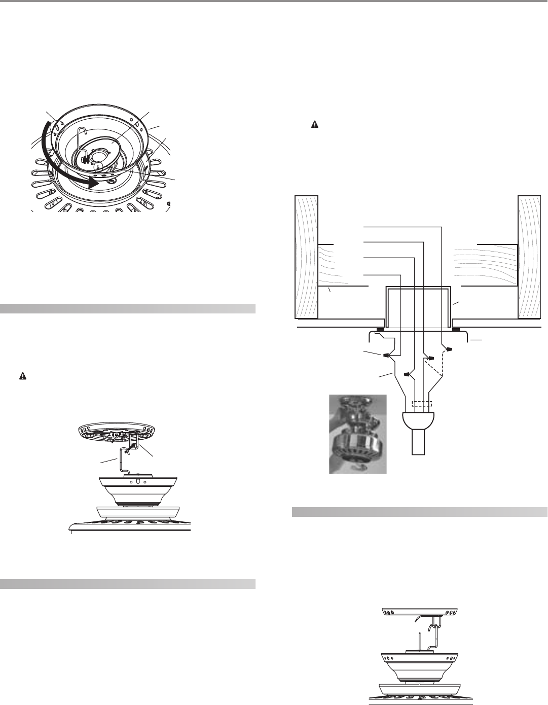
8. Rotate the canopy until the arrow on the low profile washer
aligns with the tab hole on the canopy as shown in Figure 15.
9. Align the holes in the low profile washer with the holes in the
adapter and assemble securely with the three #8-32 x 1” screws.
hanging the fan
1. Raise the fan and place the hook through the loop on the ceil-
ing plate as shown in Figure 16. Use the note and arrow en-
graved in the ceiling plate to assist in determining the direc-
tion to assemble.
WW
WW
WAA
AA
ARR
RR
RNN
NN
NII
II
INN
NN
NG: FG: F
G: FG: F
G: Faa
aa
an mn m
n mn m
n maa
aa
ay fy f
y fy f
y faa
aa
all ill i
ll ill i
ll if nf n
f nf n
f noo
oo
ot at a
t at a
t ass
ss
sss
ss
see
ee
embmb
mbmb
mbll
ll
lee
ee
ed ad a
d ad a
d as dirs dir
s dirs dir
s diree
ee
ecc
cc
ctt
tt
tee
ee
ed ind in
d ind in
d in
tt
tt
thh
hh
hee
ee
ess
ss
se ine in
e ine in
e inss
ss
stt
tt
taa
aa
allll
llll
llaa
aa
att
tt
tii
ii
ioo
oo
on inn in
n inn in
n inss
ss
stt
tt
trr
rr
ruu
uu
ucc
cc
ctt
tt
tii
ii
ioo
oo
onn
nn
nss
ss
s.....
FF
FF
Fii
ii
igg
gg
gurur
urur
ure 16 - Hae 16 - Ha
e 16 - Hae 16 - Ha
e 16 - Hann
nn
ngg
gg
ginin
inin
ing tg t
g tg t
g thh
hh
he fe f
e fe f
e faa
aa
ann
nn
n
wiring the fan
1. Disconnect the power by turning off the circuit breakers to
the outlet box and associated wall switch location.
2. You can use either one or two wall switches to control the fan
and/or lights separately. Use connection 1, as described in Fig-
ure 17, to
• control the light with a wall switch and the fan with a pull
chain (one wall switch required),
• control the light with a pull chain and the fan with a wall
switch (one wall switch required), or
• control the light with one wall switch and the fan with
another (two wall switches required).
Use connection 2, as described in Figure 17, if there is no sepa-
rate wall switch power wire for the light fixture.
NOTE: Wall switches not included.
3. Connect the wires as shown in Figure 17. To connect the wires,
twist the bare metal leads together. Place a wire nut over the
intertwined length of wire and twist clockwise until tight as.
CC
CC
CAA
AA
AUU
UU
UTT
TT
TII
II
IOO
OO
ON: BN: B
N: BN: B
N: Be se s
e se s
e surur
urur
ure ne n
e ne n
e no bo b
o bo b
o baa
aa
arr
rr
re we w
e we w
e wirir
irir
ire oe o
e oe o
e or wr w
r wr w
r wirir
irir
ire se s
e se s
e stt
tt
trr
rr
raa
aa
ann
nn
ndd
dd
ds as a
s as a
s arr
rr
re ve v
e ve v
e vii
ii
iss
ss
s--
--
-
ibib
ibib
ibll
ll
le ae a
e ae a
e aff
ff
ftt
tt
tee
ee
er mr m
r mr m
r maa
aa
akk
kk
kinin
inin
ing cg c
g cg c
g coo
oo
onnnn
nnnn
nnee
ee
ecc
cc
ctt
tt
tii
ii
ioo
oo
onn
nn
nss
ss
s.....
AA
AA
All wll w
ll wll w
ll wirir
irir
irinin
inin
ing mug mu
g mug mu
g muss
ss
st bt b
t bt b
t be in ae in a
e in ae in a
e in acc
cc
ccc
cc
coo
oo
orr
rr
rdd
dd
daa
aa
ann
nn
ncc
cc
ce we w
e we w
e wii
ii
itt
tt
th nh n
h nh n
h naa
aa
att
tt
tii
ii
ioo
oo
onn
nn
naa
aa
al al a
l al a
l ann
nn
nd ld l
d ld l
d loo
oo
occ
cc
caa
aa
all
ll
l
ee
ee
ell
ll
lee
ee
ecc
cc
ctt
tt
trr
rr
rii
ii
icc
cc
caa
aa
al cl c
l cl c
l coo
oo
odd
dd
dee
ee
es as a
s as a
s ann
nn
nd Ad A
d Ad A
d ANN
NN
NSS
SS
SI/NI/N
I/NI/N
I/NFF
FF
FPP
PP
PA 70. IA 70. I
A 70. IA 70. I
A 70. If yf y
f yf y
f yoo
oo
ou au a
u au a
u arr
rr
re une un
e une un
e unff
ff
faa
aa
amm
mm
miliili
iliili
iliaa
aa
arr
rr
r
ww
ww
wii
ii
itt
tt
th wh w
h wh w
h wirir
irir
irinin
inin
ingg
gg
g, y, y
, y, y
, yoo
oo
ou su s
u su s
u shh
hh
hoo
oo
oulul
ulul
uld ud u
d ud u
d uss
ss
se a qe a q
e a qe a q
e a quu
uu
uaa
aa
alili
lili
liff
ff
fii
ii
iee
ee
ed ed e
d ed e
d ell
ll
lee
ee
ecc
cc
ctt
tt
trr
rr
rii
ii
icc
cc
cii
ii
iaa
aa
ann
nn
n.....
FF
FF
Fii
ii
igg
gg
gurur
urur
ure 17 - We 17 - W
e 17 - We 17 - W
e 17 - Wirir
irir
irinin
inin
ing tg t
g tg t
g thh
hh
he fe f
e fe f
e faa
aa
ann
nn
n
installing the canopy
1. Rotate the fan 180º clockwise from the initial position when
hanging the fan. The arrows on the hanger ball and on the
ceiling plate should be pointing in the same direction and
should be pointing towards the tab hole on the canopy. Refer
to Figure 18.
FF
FF
Fii
ii
igg
gg
gurur
urur
ure 18 - Re 18 - R
e 18 - Re 18 - R
e 18 - Roo
oo
ott
tt
taa
aa
att
tt
tinin
inin
ing tg t
g tg t
g thh
hh
he fe f
e fe f
e faa
aa
ann
nn
n
Hook Loop
Canopy Trim Ring
Arrow on the
Low Profile
Washer
Low Profile Washer
Canopy
Tab Hole
Wall Switch Wire for Separate
Control of Light Fixture
(Note: Wall
switch must be
acceptable as a
general-use
switch.)
Power
Wires
in
Ceiling
Black
White
Bare or Green
2 x 4 Brace Outlet Box
Ceiling Plate
Approved
Connectors
Green Ground Wire from
Hanger Pipe (not present
with flush mounting
option)
Connections:
1. Connect Blk/Wht
wire from the fan to the
wall switch for separate
control of the light
fixture, or
2. Connect Blk/Wht
wire from the fan to the
ceiling black wire if there
is no separate wall
switch wire for the light
fixture.
Blk/Wht
3 Wires
from Fan
White
Black
1
2
© 2003 Hunter Fan Company 41814-01 01/14/2003
77
77
7
For Flush Mounting: The arrows on the low profile washer and
on the ceiling plate should be pointing in the same direction
and should be pointing towards the tab hole on the canopy.
2. Hook the tab hole over the tab on the ceiling plate as shown in
Figure 19.
3. Raise the canopy, be sure the holes in the canopy and the ceil-
ing plate are aligned, and loosely assemble the canopy screws
one at a time. When all three screws are assembled, securely
tighten all three canopy screws. Refer to Figure 19.
FF
FF
Fii
ii
igg
gg
gurur
urur
ure 19 - Ie 19 - I
e 19 - Ie 19 - I
e 19 - Inn
nn
nss
ss
stt
tt
taa
aa
allinllin
llinllin
lling tg t
g tg t
g thh
hh
he ce c
e ce c
e caa
aa
ann
nn
noo
oo
opp
pp
pyy
yy
y
installing the canopy trim ring
1. To easily install the canopy trim ring, locate the two tabs on
the canopy trim ring. See Figure 20.
FF
FF
Fii
ii
igg
gg
gurur
urur
ure 20 - Ce 20 - C
e 20 - Ce 20 - C
e 20 - Caa
aa
ann
nn
noo
oo
opp
pp
py ty t
y ty t
y trr
rr
rim rim r
im rim r
im rinin
inin
ingg
gg
g
2. Take both hands and push the canopy trim ring up to the top
of the canopy. See Figure 20.
3. The canopy trim ring will snap and lock into place on the
canopy.
removing the canopy trim ring
1. Locate the tab indicators, small bumps on top of tabs. Refer to
Figure 21.
2. To remove the canopy trim ring, press firmly on opposite sides
of the ring towards the canopy as shown in Figure 21. The tabs
will flex out releasing the trim ring from the canopy.
FF
FF
Fii
ii
igg
gg
gurur
urur
ure 21 - Re 21 - R
e 21 - Re 21 - R
e 21 - Ree
ee
emm
mm
moo
oo
ovv
vv
vinin
inin
ing tg t
g tg t
g thh
hh
he ce c
e ce c
e caa
aa
ann
nn
noo
oo
opp
pp
py ty t
y ty t
y trr
rr
rim rim r
im rim r
im rinin
inin
ingg
gg
g
assembling the blades
Hunter fans use several styles of fan blade irons (brackets that hold
the blade to the fan).
1. Your fan may include blade grommets. If your fan has grom-
mets, insert them by hand into the holes on the blades as shown
in Figure 22.
FF
FF
Fii
ii
igg
gg
gurur
urur
ure 22 - Ie 22 - I
e 22 - Ie 22 - I
e 22 - Inn
nn
nss
ss
see
ee
err
rr
rtt
tt
tinin
inin
ing tg t
g tg t
g thh
hh
he ge g
e ge g
e grr
rr
roo
oo
ommmm
mmmm
mmee
ee
ett
tt
ts ins in
s ins in
s intt
tt
to to t
o to t
o thh
hh
he fe f
e fe f
e faa
aa
an bn b
n bn b
n bll
ll
laa
aa
add
dd
dee
ee
ess
ss
s
2. Attach each blade to blade iron using three blade assembly
screws as shown in Figure 23. Some fans feature a decorative
medallion as well as a blade iron. Insert the assembly screws
into the blade iron, through the blade and into the medallion,
with the blade sandwiched between the blade iron and me-
dallion as shown in Figure 24.
FF
FF
Fii
ii
igg
gg
gurur
urur
ure 23 - Ae 23 - A
e 23 - Ae 23 - A
e 23 - Att
tt
ttt
tt
taa
aa
acc
cc
chh
hh
hinin
inin
ing tg t
g tg t
g thh
hh
he be b
e be b
e bll
ll
laa
aa
add
dd
de te t
e te t
e to to t
o to t
o thh
hh
he be b
e be b
e bll
ll
laa
aa
add
dd
de ire ir
e ire ir
e iroo
oo
onn
nn
n
Tab Hole
and Tab
Canopy
Screw
Canopy
Canopy
Trim Ring Tab
Press Here when
Removing
Press Here when
Removing
Grommet
Fan Blade
Canopy Trim Ring
Canopy
Tab Indicator
41814-01 01/14/2003 © 2003 Hunter Fan Company
88
88
8
FF
FF
Fii
ii
igg
gg
gurur
urur
ure 24 - Ae 24 - A
e 24 - Ae 24 - A
e 24 - Att
tt
ttt
tt
taa
aa
acc
cc
chh
hh
hinin
inin
ing tg t
g tg t
g thh
hh
he be b
e be b
e bll
ll
laa
aa
add
dd
de te t
e te t
e to to t
o to t
o thh
hh
he be b
e be b
e bll
ll
laa
aa
add
dd
de ire ir
e ire ir
e iroo
oo
on an a
n an a
n ann
nn
ndd
dd
d
mm
mm
mee
ee
edd
dd
daa
aa
allilli
llilli
llioo
oo
onn
nn
n
If you used grommets, the blades may appear slightly loose
after screws are tightened. This is normal.
3. Remove the blade mounting screws and rubber shipping
bumpers from the motor.
4. For each blade, insert one blade mounting screw through the
blade iron as shown in Figure 25, and attach lightly to the fan.
Insert the second blade mounting screw, then securely tighten
both mounting screws.
FF
FF
Fii
ii
igg
gg
gurur
urur
ure 25 - Ae 25 - A
e 25 - Ae 25 - A
e 25 - Att
tt
ttt
tt
taa
aa
acc
cc
chh
hh
hinin
inin
ing tg t
g tg t
g thh
hh
he be b
e be b
e bll
ll
laa
aa
add
dd
de ire ir
e ire ir
e iroo
oo
on tn t
n tn t
n to to t
o to t
o thh
hh
he fe f
e fe f
e faa
aa
ann
nn
n
installing the light fixture
You can install with or without the light fixture. If you want to
install without the light fixture, skip to the inin
inin
inss
ss
stt
tt
taa
aa
allinllin
llinllin
lling wg w
g wg w
g wii
ii
itt
tt
thh
hh
hoo
oo
ouu
uu
ut tt t
t tt t
t thh
hh
hee
ee
e
lili
lili
ligg
gg
ghh
hh
ht ft f
t ft f
t fii
ii
ixx
xx
xtt
tt
turur
urur
uree
ee
e section.
WW
WW
WAA
AA
ARR
RR
RNN
NN
NII
II
INN
NN
NG: UsG: Us
G: UsG: Us
G: Use oe o
e oe o
e onlnl
nlnl
nly ty t
y ty t
y thh
hh
he se s
e se s
e supup
upup
uppp
pp
plili
lili
liee
ee
ed lid li
d lid li
d ligg
gg
ghh
hh
ht ft f
t ft f
t fii
ii
ixx
xx
xtt
tt
turur
urur
ure fe f
e fe f
e foo
oo
or tr t
r tr t
r thh
hh
hii
ii
is fs f
s fs f
s faa
aa
ann
nn
n
mm
mm
moo
oo
odd
dd
dee
ee
el.l.
l.l.
l.
attaching the upper switch housing
1. Partially install two #6-32 x 3/8" housing assembly screws into
the switch housing mounting plate as shown in Figure 26.
2. Feed the upper plug connector through the center opening of
the upper switch housing. See Figure 26.
FF
FF
Fii
ii
igg
gg
gurur
urur
ure 26 - Ae 26 - A
e 26 - Ae 26 - A
e 26 - Att
tt
ttt
tt
taa
aa
acc
cc
chh
hh
hinin
inin
ing tg t
g tg t
g thh
hh
he upe up
e upe up
e uppp
pp
pee
ee
er sr s
r sr s
r sww
ww
wii
ii
itt
tt
tcc
cc
ch hh h
h hh h
h hoo
oo
ouu
uu
usinsin
sinsin
sing tg t
g tg t
g to to t
o to t
o thh
hh
hee
ee
e
mm
mm
moo
oo
ounun
unun
untt
tt
tinin
inin
ing pg p
g pg p
g pll
ll
laa
aa
att
tt
tee
ee
e
3. Align the keyhole slots in the upper switch housing with the
housing assembly screws installed previously.
4. Turn the upper switch housing counterclockwise until the
housing assembly screws are firmly situated in the narrow end
of the keyhole slots as shown in Figure 27. Install the one re-
maining #6-32 x 3/8" housing assembly screw into the third
hole in the upper switch housing. Tighten all three screws firmly.
FF
FF
Fii
ii
igg
gg
gurur
urur
ure 27 - Me 27 - M
e 27 - Me 27 - M
e 27 - Moo
oo
ounun
unun
untt
tt
tinin
inin
ing tg t
g tg t
g thh
hh
he upe up
e upe up
e uppp
pp
pee
ee
er sr s
r sr s
r sww
ww
wii
ii
itt
tt
tcc
cc
ch hh h
h hh h
h hoo
oo
ouu
uu
usinsin
sinsin
singg
gg
g
CC
CC
CAA
AA
AUU
UU
UTT
TT
TII
II
IOO
OO
ON: MN: M
N: MN: M
N: Maa
aa
akk
kk
ke se s
e se s
e surur
urur
ure te t
e te t
e thh
hh
he upe up
e upe up
e uppp
pp
pee
ee
er sr s
r sr s
r sww
ww
wii
ii
itt
tt
tcc
cc
ch hh h
h hh h
h hoo
oo
ouu
uu
usinsin
sinsin
sing ig i
g ig i
g is ss s
s ss s
s se-e-
e-e-
e-
cc
cc
curur
urur
uree
ee
ell
ll
ly ay a
y ay a
y att
tt
ttt
tt
taa
aa
acc
cc
chh
hh
hee
ee
ed td t
d td t
d to to t
o to t
o thh
hh
he se s
e se s
e sww
ww
wii
ii
itt
tt
tcc
cc
ch hh h
h hh h
h hoo
oo
ouu
uu
usinsin
sinsin
sing mg m
g mg m
g moo
oo
ounun
unun
untt
tt
tinin
inin
ing pg p
g pg p
g pll
ll
laa
aa
att
tt
tee
ee
e. F. F
. F. F
. Faa
aa
ail-il-
il-il-
il-
urur
urur
ure te t
e te t
e to po p
o po p
o prr
rr
roo
oo
opp
pp
pee
ee
err
rr
rll
ll
ly ay a
y ay a
y att
tt
ttt
tt
taa
aa
acc
cc
ch ah a
h ah a
h ann
nn
nd td t
d td t
d tii
ii
igg
gg
ghh
hh
htt
tt
tee
ee
en an a
n an a
n all tll t
ll tll t
ll thrhr
hrhr
hree
ee
ee he h
e he h
e hoo
oo
ouu
uu
usinsin
sinsin
sing ag a
g ag a
g ass
ss
s--
--
-
ss
ss
see
ee
embmb
mbmb
mbll
ll
ly sy s
y sy s
y scc
cc
crr
rr
ree
ee
eww
ww
ws cs c
s cs c
s coo
oo
oulul
ulul
uld rd r
d rd r
d ree
ee
ess
ss
sulul
ulul
ult in tt in t
t in tt in t
t in thh
hh
he se s
e se s
e sww
ww
wii
ii
itt
tt
tcc
cc
ch hh h
h hh h
h hoo
oo
ouu
uu
usinsin
sinsin
sing ag a
g ag a
g ann
nn
nd lid li
d lid li
d ligg
gg
ghh
hh
htt
tt
t
ff
ff
fii
ii
ixx
xx
xtt
tt
turur
urur
ure fe f
e fe f
e faa
aa
allinllin
llinllin
llingg
gg
g.....
attaching the light fixture
Refer to Figure 28.
1. Remove the plug cap from the lower switch housing.
NN
NN
Noo
oo
ott
tt
te:e:
e:e:
e: Do not discard the plug cap. You will need this if you
remove the light fixture in the future.
2. Remove top housing from the light fixture by loosening the
three screws and turning counter clockwise.
3. Locate the two wires in the lower switch housing labeled “Con-
nect Light Here” or “For Light Use”. One will be white, the other
black/white. Unscrew the wire nuts counterclockwise to ex-
pose the bare metal leads.
4. Place these wires into the hole in the center of the top housing
for the light kit. Slide the top housing over the two wires.
5. Screw the fixture into the lower switch housing. Thread the
lockwasher and nut provided over the wires. Making sure the
light fixture mounting screw holes are aligned; hold the light
fixture and tighten the nut on the inside of the lower switch
housing. Insert and tighten the two #6-32 sems light fixture
mounting screws. Refer to Figure 28.
6. Locate the white wire and the black wire coming from the light
fixture.
Blade Iron
Medallion
Switch Housing
Mounting Plate
Upper Switch
Housing
Housing
Assembly
Screw
Upper Plug
Connector
© 2003 Hunter Fan Company 41814-01 01/14/2003
99
99
9
7. Thread the two wires from the light fixture through the center
hole in the lower switch housing.
8. Connect the black wire from the light fixture to the black/white
wire from the lower switch housing.
Connect the white wire from the light fixture to the white wire
from the lower switch housing.
To fasten the wires, twist the two bare leads together. Place a
wire nut over the intertwined length of wire and twist clock-
wise until tight.
FF
FF
Fii
ii
igg
gg
gurur
urur
ure 28 - Ae 28 - A
e 28 - Ae 28 - A
e 28 - Att
tt
ttt
tt
taa
aa
acc
cc
chh
hh
hinin
inin
ing tg t
g tg t
g thh
hh
he lie li
e lie li
e ligg
gg
ghh
hh
ht ft f
t ft f
t fii
ii
ixx
xx
xtt
tt
turur
urur
uree
ee
e
9. Install the light kit on the top housing so that the three screws
are aligned with the mounting holes of the light kit. Insert and
tighten the three housing screws.
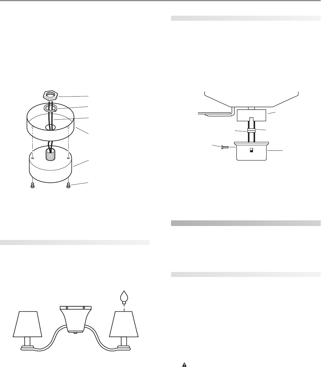
installing the paper shades
Refer to Figure 29.
1. Light shades are installed on top of the candlestick containing
the light socket. Press down securely on top of shade.
2. Install three max 40 Watt standard candelabra base incandes-
cent bulbs.
FF
FF
Fii
ii
igg
gg
gurur
urur
ure 29 - Ie 29 - I
e 29 - Ie 29 - I
e 29 - Inn
nn
nss
ss
stt
tt
taa
aa
allinllin
llinllin
lling tg t
g tg t
g thh
hh
he ke k
e ke k
e krr
rr
raa
aa
aff
ff
ft pt p
t pt p
t paa
aa
app
pp
pee
ee
er sr s
r sr s
r shh
hh
haa
aa
add
dd
dee
ee
ess
ss
s
Lower Plug
Connector
Upper Switch
Housing
Upper Plug
Connector
Lower
Switch
Housing
Housing
Assembly
Screw
attaching the lower switch housing
1. Connect the upper plug connector from the motor to the lower
plug connector in the lower switch housing assembly. See Fig-
ure 30.
NOTE: Both plug connectors are polarized and will only fit to-
gether one way. Make sure that both connectors are properly
aligned before connecting them together. Incorrect connec-
tion could cause improper operation and damage to the prod-
uct.
FF
FF
Fii
ii
igg
gg
gurur
urur
ure 30 - Ce 30 - C
e 30 - Ce 30 - C
e 30 - Coo
oo
onnnn
nnnn
nnee
ee
ecc
cc
ctt
tt
tinin
inin
ing tg t
g tg t
g thh
hh
he pe p
e pe p
e plulu
lulu
lug cg c
g cg c
g coo
oo
onnnn
nnnn
nnee
ee
ecc
cc
ctt
tt
too
oo
orr
rr
rss
ss
s
2. Place the lower switch housing assembly over the upper switch
housing. Align the side screw holes in the upper and lower
switch housings. Attach the lower switch housing to the up-
per switch housing with three #6-32 x 3/8" housing assembly
screws. See Figure 30.
installing without the light fixture
Your Hunter fan comes with a light fixture assembly. This feature
gives you the option of installing the fan with or without the in-
cluded light fixture.
If you decide to install the fan without the light fixture please com-
plete the following instructions.
attaching the upper switch housing
1. Partially install two #6-32 x 3/8" housing assembly screws into
the switch housing mounting plate as shown in Figure 26.
2. Feed the upper plug connector through the center opening of
the upper switch housing. See Figure 26.
3. Align the keyhole slots in the upper switch housing with the
housing assembly screws installed previously.
4. Turn the upper switch housing counterclockwise until the
housing assembly screws are firmly situated in the narrow end
of the keyhole slots as shown in Figure 27. Install the one re-
maining #6-32 x 3/8" housing assembly screw into the third
hole in the upper switch housing. Tighten all three screws firmly.
CC
CC
CAA
AA
AUU
UU
UTT
TT
TII
II
IOO
OO
ON: MN: M
N: MN: M
N: Maa
aa
akk
kk
ke se s
e se s
e surur
urur
ure te t
e te t
e thh
hh
he upe up
e upe up
e uppp
pp
pee
ee
er sr s
r sr s
r sww
ww
wii
ii
itt
tt
tcc
cc
ch hh h
h hh h
h hoo
oo
ouu
uu
usinsin
sinsin
sing ig i
g ig i
g is ss s
s ss s
s se-e-
e-e-
e-
cc
cc
curur
urur
uree
ee
ell
ll
ly ay a
y ay a
y att
tt
ttt
tt
taa
aa
acc
cc
chh
hh
hee
ee
ed td t
d td t
d to to t
o to t
o thh
hh
he se s
e se s
e sww
ww
wii
ii
itt
tt
tcc
cc
ch hh h
h hh h
h hoo
oo
ouu
uu
usinsin
sinsin
sing mg m
g mg m
g moo
oo
ounun
unun
untt
tt
tinin
inin
ing pg p
g pg p
g pll
ll
laa
aa
att
tt
tee
ee
e. F. F
. F. F
. Faa
aa
ail-il-
il-il-
il-
urur
urur
ure te t
e te t
e to po p
o po p
o prr
rr
roo
oo
opp
pp
pee
ee
err
rr
rll
ll
ly ay a
y ay a
y att
tt
ttt
tt
taa
aa
acc
cc
ch ah a
h ah a
h ann
nn
nd td t
d td t
d tii
ii
igg
gg
ghh
hh
htt
tt
tee
ee
en an a
n an a
n all tll t
ll tll t
ll thrhr
hrhr
hree
ee
ee he h
e he h
e hoo
oo
ouu
uu
usinsin
sinsin
sing ag a
g ag a
g ass
ss
s--
--
-
ss
ss
see
ee
embmb
mbmb
mbll
ll
ly sy s
y sy s
y scc
cc
crr
rr
ree
ee
eww
ww
ws cs c
s cs c
s coo
oo
oulul
ulul
uld rd r
d rd r
d ree
ee
ess
ss
sulul
ulul
ult in tt in t
t in tt in t
t in thh
hh
he se s
e se s
e sww
ww
wii
ii
itt
tt
tcc
cc
ch hh h
h hh h
h hoo
oo
ouu
uu
usinsin
sinsin
sing ag a
g ag a
g ann
nn
nd lid li
d lid li
d ligg
gg
ghh
hh
htt
tt
t
ff
ff
fii
ii
ixx
xx
xtt
tt
turur
urur
ure fe f
e fe f
e faa
aa
allinllin
llinllin
llingg
gg
g.....
Nut
Lockwasher
Light Fixture Wires
Lower Switch Housing
Light Fixture
Light Fixture
Mounting Screws
41814-01 01/14/2003 © 2003 Hunter Fan Company
1010
1010
10
installing the lower switch housing
1. Connect the upper plug connector from the motor to the lower
plug connector in the lower switch housing assembly. See Fig-
ure 30
NOTE: Both plug connectors are polarized and will only fit to-
gether one way. Make sure that both connectors are properly
aligned before connecting them together. Incorrect connec-
tion could cause improper operation and damage to the prod-
uct.
2. Place the lower switch housing assembly over the upper switch
housing. Align the side screw holes in the upper and lower
switch housings. Attach the lower switch housing to the up-
per switch housing with three #6-32 x 3/8" housing assembly
screws. See Figure 30.
Fan Pull
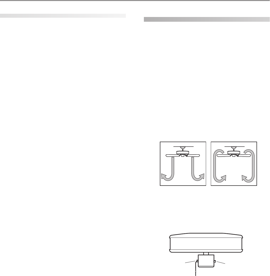
Chain
Reversing
Switch
operating your ceiling fan
1. Turn on electrical power to the fan.
2. The fan pull chain controls power to the fan. The pull chain
has four settings in sequence: High, Medium, Low and Off.
• Pull the chain slowly to change settings.
• Release slowly to prevent the chain from recoiling into the
blades.
• The chain uses a breakaway connector that separates if
the chain is jerked. If this happens, simply reinsert the chain
into the connector.
3. The light pull chain controls power to the light. The pull chain
has two settings: On and Off.
4. Ceiling fans work best by blowing air downward (counterclock-
wise blade rotation) in warm weather to cool the room with a
direct breeze. In winter, having the fan draw air upward (clock-
wise blade rotation) will distribute the warmer air trapped at
the ceiling around the room without causing a draft. Refer to
Figure 31.
FF
FF
Fii
ii
igg
gg
gurur
urur
ure 31 - Ae 31 - A
e 31 - Ae 31 - A
e 31 - Air fir f
ir fir f
ir fll
ll
loo
oo
ow pw p
w pw p
w paa
aa
att
tt
ttt
tt
tee
ee
err
rr
rnn
nn
nss
ss
s
To change the direction of air flow, turn the fan off and let it
come to a complete stop. Slide the reversing switch on the fan
to the opposite position as shown in Figure 32. Restart fan.
FF
FF
Fii
ii
igg
gg
gurur
urur
ure 32 - Pe 32 - P
e 32 - Pe 32 - P
e 32 - Pull cull c
ull cull c
ull chh
hh
haa
aa
ain ain a
in ain a
in ann
nn
nd rd r
d rd r
d ree
ee
evv
vv
vee
ee
err
rr
rsinsin
sinsin
sing sg s
g sg s
g sww
ww
wii
ii
itt
tt
tcc
cc
chh
hh
h

© 2003 Hunter Fan Company 41814-01 01/14/2003
1111
1111
11
cleaning your ceiling fan
caring for finishes
For cleaning, a soft brush or lint-free cloth should be used to pre-
vent scratching the finish. A vacuum cleaner brush nozzle can re-
move heavier dust. Surface smudges or an accumulation of dirt
and dust can easily be removed by using a mild detergent and a
slightly dampened cloth. An artistic agent may be used, but never
use abrasive cleaning agents as they will damage the finish.
caring for blades
Wood finish blades should be cleaned with a furniture polishing
cloth. Occasionally, a light coat of furniture polish may be applied
for added protection and beauty. Painted and high-gloss blades
may be cleaned in the same manner as the fan finish.
troubleshooting
Problem: Nothing happens; fan does not move.
1. Turn power on, replace fuse, or reset breaker.
2. Loosen canopy, check all connections according to the
ww
ww
wirir
irir
irinin
inin
ing tg t
g tg t
g thh
hh
he fe f
e fe f
e faa
aa
ann
nn
n section.
3. Check the plug connection in the switch housing.
4. Push motor reversing switch firmly up or down to ensure
that the switch is engaged.
5. Pull the pull chain to ensure it is on.
6. Remove the shipping bumpers.
Problem: Noisy operation.
1. Tighten the blade bracket screws until snug.
2. Tighten the blade screws until snug.
3. Check to see if the blade is cracked. If so, replace all the
blades.
4. Change to an approved speed control.
5. Be sure that the glass is secure.
6. Check and tighten the screws in the switch housing
mounting plate and in the upper and lower switch hous-
ing.
Problem: Excessive wobbling.
1. If your fan wobbles when operating, use the enclosed bal-
ancing kit and instructions to balance the fan.
2. Tighten all blade and/or blade iron screws.
3. Turn power off, support fan very carefully, and check that
the hanger ball is properly seated.
If you need parts or service assistance, please call 888-830-1326 or
visit us at our WEB site at http://www.hunterfan.com.
Hunter Fan Company
2500 Frisco Avenue
Memphis, Tennessee 38114
