Hunter Fan TX17 Remote control for ceiling fan and attached lamp User Manual new format
Hunter Fan Company Remote control for ceiling fan and attached lamp new format
Users Manual

© 2003 Hunter Fan Company 41825-01 02/05/2003
11
11
1
41825-01 02/05/2003 © 2003 Hunter Fan Company
22
22
2
Your new Hunter® ceiling fan is an addition to your home or office
that will provide comfort and performance for many years. This
installation and operation manual gives you complete instructions
for installing and operating your fan.
We are proud of our work. We appreciate the opportunity to sup-
ply you with the best ceiling fan available anywhere in the world.
Before installing your fan, record the following information for your
records and warranty assistance. Please refer to the carton and the
Hunter nameplate label (located on the top of the fan motor hous-
ing) for the proper information.
Model Name: __________________________
Catalog/Model No.: ______________
Serial No.: _____________________
Date Purchased: ___ / ___ / ______
Where Purchased: _______________________________
Please also attach your receipt or a copy of your receipt for refer-
ence.
cautions and warnings
••
••
•RR
RR
Ree
ee
eaa
aa
ad ed e
d ed e
d enn
nn
ntt
tt
tirir
irir
ire be b
e be b
e boo
oo
ooo
oo
okk
kk
kll
ll
lee
ee
et ct c
t ct c
t caa
aa
arr
rr
ree
ee
eff
ff
fullull
ullull
ully by b
y by b
y bee
ee
eff
ff
foo
oo
orr
rr
re be b
e be b
e bee
ee
egg
gg
ginninn
inninn
inninin
inin
ing ing in
g ing in
g inss
ss
stt
tt
taa
aa
al-l-
l-l-
l-
ll
ll
laa
aa
att
tt
tii
ii
ioo
oo
onn
nn
n. S. S
. S. S
. Saa
aa
avv
vv
ve te t
e te t
e thh
hh
hee
ee
ess
ss
se ine in
e ine in
e inss
ss
stt
tt
trr
rr
ruu
uu
ucc
cc
ctt
tt
tii
ii
ioo
oo
onn
nn
nss
ss
s.....
••
••
•UsUs
UsUs
Use oe o
e oe o
e onlnl
nlnl
nly Hy H
y Hy H
y Hunun
unun
untt
tt
tee
ee
er rr r
r rr r
r ree
ee
epp
pp
pll
ll
laa
aa
acc
cc
cee
ee
emm
mm
mee
ee
enn
nn
nt pt p
t pt p
t paa
aa
arr
rr
rtt
tt
tss
ss
s.....
••
••
•TT
TT
To ro r
o ro r
o ree
ee
edudu
dudu
ducc
cc
ce te t
e te t
e thh
hh
he re r
e re r
e rii
ii
iss
ss
sk ok o
k ok o
k of pf p
f pf p
f pee
ee
err
rr
rss
ss
soo
oo
onn
nn
naa
aa
al inl in
l inl in
l injurjur
jurjur
juryy
yy
y, a, a
, a, a
, att
tt
ttt
tt
taa
aa
acc
cc
ch th t
h th t
h thh
hh
he fe f
e fe f
e faa
aa
ann
nn
n
dirdir
dirdir
diree
ee
ecc
cc
ctt
tt
tll
ll
ly ty t
y ty t
y to to t
o to t
o thh
hh
he se s
e se s
e supup
upup
uppp
pp
poo
oo
orr
rr
rt st s
t st s
t stt
tt
trr
rr
ruu
uu
ucc
cc
ctt
tt
turur
urur
ure oe o
e oe o
e of tf t
f tf t
f thh
hh
he be b
e be b
e builuil
uiluil
uildindin
dindin
ding ag a
g ag a
g acc
cc
c--
--
-
cc
cc
coo
oo
orr
rr
rdindin
dindin
ding tg t
g tg t
g to to t
o to t
o thh
hh
hee
ee
ess
ss
se ine in
e ine in
e inss
ss
stt
tt
trr
rr
ruu
uu
ucc
cc
ctt
tt
tii
ii
ioo
oo
onn
nn
nss
ss
s, a, a
, a, a
, ann
nn
nd ud u
d ud u
d uss
ss
se oe o
e oe o
e onlnl
nlnl
nly ty t
y ty t
y thh
hh
he he h
e he h
e haa
aa
arr
rr
rd-d-
d-d-
d-
ww
ww
waa
aa
arr
rr
re se s
e se s
e supup
upup
uppp
pp
plili
lili
liee
ee
ed.d.
d.d.
d.
••
••
•TT
TT
To ao a
o ao a
o avv
vv
voo
oo
oii
ii
id pd p
d pd p
d poo
oo
oss
ss
ssibsib
sibsib
sibll
ll
le ee e
e ee e
e ell
ll
lee
ee
ecc
cc
ctt
tt
trr
rr
rii
ii
icc
cc
caa
aa
al sl s
l sl s
l shh
hh
hoo
oo
occ
cc
ckk
kk
k, b, b
, b, b
, bee
ee
eff
ff
foo
oo
orr
rr
re ine in
e ine in
e inss
ss
stt
tt
taa
aa
allinllin
llinllin
llingg
gg
g
yy
yy
yoo
oo
our fur f
ur fur f
ur faa
aa
ann
nn
n, di, di
, di, di
, diss
ss
scc
cc
coo
oo
onnnn
nnnn
nnee
ee
ecc
cc
ct tt t
t tt t
t thh
hh
he pe p
e pe p
e poo
oo
oww
ww
wee
ee
er br b
r br b
r by ty t
y ty t
y turur
urur
urnn
nn
ninin
inin
ing og o
g og o
g off
ff
ff tf t
f tf t
f thh
hh
he ce c
e ce c
e cirir
irir
ir--
--
-
cc
cc
cuiui
uiui
uit bt b
t bt b
t brr
rr
ree
ee
eaa
aa
akk
kk
kee
ee
err
rr
rs ts t
s ts t
s to to t
o to t
o thh
hh
he oe o
e oe o
e ouu
uu
utt
tt
tll
ll
lee
ee
et bt b
t bt b
t boo
oo
ox ax a
x ax a
x ann
nn
nd ad a
d ad a
d ass
ss
sss
ss
soo
oo
occ
cc
cii
ii
iaa
aa
att
tt
tee
ee
ed wd w
d wd w
d waa
aa
allll
llll
ll
ss
ss
sww
ww
wii
ii
itt
tt
tcc
cc
ch lh l
h lh l
h loo
oo
occ
cc
caa
aa
att
tt
tii
ii
ioo
oo
onn
nn
n. I. I
. I. I
. If yf y
f yf y
f yoo
oo
ou cu c
u cu c
u caa
aa
annnn
nnnn
nnoo
oo
ot lt l
t lt l
t loo
oo
occ
cc
ck tk t
k tk t
k thh
hh
he ce c
e ce c
e cirir
irir
ircc
cc
cuiui
uiui
uit bt b
t bt b
t brr
rr
ree
ee
eaa
aa
akk
kk
k--
--
-
ee
ee
err
rr
rs in ts in t
s in ts in t
s in thh
hh
he oe o
e oe o
e off
ff
ff pf p
f pf p
f poo
oo
osisi
sisi
sitt
tt
tii
ii
ioo
oo
onn
nn
n, s, s
, s, s
, see
ee
ecc
cc
curur
urur
uree
ee
ell
ll
ly fy f
y fy f
y faa
aa
ass
ss
stt
tt
tee
ee
en a pn a p
n a pn a p
n a prr
rr
roo
oo
omm
mm
minin
inin
inee
ee
enn
nn
ntt
tt
t
ww
ww
waa
aa
arr
rr
rnn
nn
ninin
inin
ing dg d
g dg d
g dee
ee
evv
vv
vii
ii
icc
cc
cee
ee
e, s, s
, s, s
, suu
uu
ucc
cc
ch ah a
h ah a
h as a ts a t
s a ts a t
s a taa
aa
agg
gg
g, t, t
, t, t
, to to t
o to t
o thh
hh
he se s
e se s
e see
ee
err
rr
rvv
vv
vii
ii
icc
cc
ce pe p
e pe p
e paa
aa
ann
nn
nee
ee
el.l.
l.l.
l.
••
••
•AA
AA
All wll w
ll wll w
ll wirir
irir
irinin
inin
ing mug mu
g mug mu
g muss
ss
st bt b
t bt b
t be in ae in a
e in ae in a
e in acc
cc
ccc
cc
coo
oo
orr
rr
rdd
dd
daa
aa
ann
nn
ncc
cc
ce we w
e we w
e wii
ii
itt
tt
th nh n
h nh n
h naa
aa
att
tt
tii
ii
ioo
oo
onn
nn
naa
aa
al al a
l al a
l ann
nn
ndd
dd
d
ll
ll
loo
oo
occ
cc
caa
aa
al el e
l el e
l ell
ll
lee
ee
ecc
cc
ctt
tt
trr
rr
rii
ii
icc
cc
caa
aa
al cl c
l cl c
l coo
oo
odd
dd
dee
ee
es as a
s as a
s ann
nn
nd Ad A
d Ad A
d ANN
NN
NSS
SS
SI/NI/N
I/NI/N
I/NFF
FF
FPP
PP
PA 70. IA 70. I
A 70. IA 70. I
A 70. If yf y
f yf y
f yoo
oo
ou au a
u au a
u arr
rr
ree
ee
e
unun
unun
unff
ff
faa
aa
amm
mm
miliili
iliili
iliaa
aa
ar wr w
r wr w
r wii
ii
itt
tt
th wh w
h wh w
h wirir
irir
irinin
inin
ingg
gg
g, y, y
, y, y
, yoo
oo
ou su s
u su s
u shh
hh
hoo
oo
oulul
ulul
uld ud u
d ud u
d uss
ss
se a qe a q
e a qe a q
e a quu
uu
uaa
aa
alili
lili
liff
ff
fii
ii
iee
ee
ed ed e
d ed e
d ell
ll
lee
ee
ecc
cc
c--
--
-
tt
tt
trr
rr
rii
ii
icc
cc
cii
ii
iaa
aa
ann
nn
n.....
••
••
•TT
TT
To ro r
o ro r
o ree
ee
edudu
dudu
ducc
cc
ce te t
e te t
e thh
hh
he re r
e re r
e rii
ii
iss
ss
sk ok o
k ok o
k of pf p
f pf p
f pee
ee
err
rr
rss
ss
soo
oo
onn
nn
naa
aa
al inl in
l inl in
l injurjur
jurjur
juryy
yy
y, d, d
, d, d
, do no n
o no n
o noo
oo
ot bt b
t bt b
t bee
ee
enn
nn
nd td t
d td t
d thh
hh
hee
ee
e
bb
bb
bll
ll
laa
aa
add
dd
de ae a
e ae a
e att
tt
ttt
tt
taa
aa
acc
cc
chmhm
hmhm
hmee
ee
enn
nn
nt st s
t st s
t syy
yy
yss
ss
stt
tt
tee
ee
em wm w
m wm w
m whh
hh
hee
ee
en inn in
n inn in
n inss
ss
stt
tt
taa
aa
allinllin
llinllin
llingg
gg
g, b, b
, b, b
, baa
aa
all
ll
laa
aa
ann
nn
ncc
cc
cinin
inin
ingg
gg
g,,,,,
oo
oo
or cr c
r cr c
r cll
ll
lee
ee
eaa
aa
ann
nn
ninin
inin
ing tg t
g tg t
g thh
hh
he fe f
e fe f
e faa
aa
ann
nn
n. N. N
. N. N
. Nee
ee
evv
vv
vee
ee
er inr in
r inr in
r inss
ss
see
ee
err
rr
rt ft f
t ft f
t foo
oo
orr
rr
ree
ee
eii
ii
igg
gg
gn on o
n on o
n obb
bb
bjj
jj
jee
ee
ecc
cc
ctt
tt
ts bs b
s bs b
s be-e-
e-e-
e-
tt
tt
tww
ww
wee
ee
eee
ee
en rn r
n rn r
n roo
oo
ott
tt
taa
aa
att
tt
tinin
inin
ing fg f
g fg f
g faa
aa
an bn b
n bn b
n bll
ll
laa
aa
add
dd
dee
ee
ess
ss
s.....
••
••
•TT
TT
To ro r
o ro r
o ree
ee
edudu
dudu
ducc
cc
ce te t
e te t
e thh
hh
he re r
e re r
e rii
ii
iss
ss
sk ok o
k ok o
k of ff f
f ff f
f firir
irir
iree
ee
e, e, e
, e, e
, ell
ll
lee
ee
ecc
cc
ctt
tt
trr
rr
rii
ii
icc
cc
caa
aa
al sl s
l sl s
l shh
hh
hoo
oo
occ
cc
ckk
kk
k, o, o
, o, o
, or mr m
r mr m
r moo
oo
ott
tt
too
oo
orr
rr
r
dd
dd
daa
aa
amm
mm
maa
aa
agg
gg
gee
ee
e, d, d
, d, d
, do no n
o no n
o noo
oo
ot ut u
t ut u
t uss
ss
se a se a s
e a se a s
e a soo
oo
olili
lili
lid-d-
d-d-
d-ss
ss
stt
tt
taa
aa
att
tt
te se s
e se s
e spp
pp
pee
ee
eee
ee
ed cd c
d cd c
d coo
oo
onn
nn
ntt
tt
trr
rr
roo
oo
ol wl w
l wl w
l wii
ii
itt
tt
thh
hh
h
tt
tt
thh
hh
hii
ii
is fs f
s fs f
s faa
aa
ann
nn
n. Us. Us
. Us. Us
. Use oe o
e oe o
e onlnl
nlnl
nly Hy H
y Hy H
y Hunun
unun
untt
tt
tee
ee
er sr s
r sr s
r spp
pp
pee
ee
eee
ee
ed cd c
d cd c
d coo
oo
onn
nn
ntt
tt
trr
rr
roo
oo
oll
ll
lss
ss
s.....
••
••
•CC
CC
Cee
ee
eilinilin
ilinilin
iling hg h
g hg h
g hee
ee
eii
ii
igg
gg
ghh
hh
ht mut mu
t mut mu
t muss
ss
st bt b
t bt b
t be a me a m
e a me a m
e a minin
inin
inimum oimum o
imum oimum o
imum of 9 ff 9 f
f 9 ff 9 f
f 9 fee
ee
eee
ee
ett
tt
t.....
getting ready
To install a ceiling fan, be sure you can do the following:
• Locate the ceiling joist or other suitable support in ceil-
ing.
• Drill holes for and install wood screws.
• Identify and connect electrical wires.
• Lift 40 pounds.
If you need help installing the fan, your Hunter fan dealer can di-
rect you to a licensed installer or electrician.
gathering the tools
You will need the following tools for installing the fan:
• Electric drill with 9/64" bit
• Standard screwdriver
• Phillips-head screwdriver
• Wrench or pliers
considering optional accessories
Consider using Hunter’s optional accessories, including a wall-
mounted or remote speed control. To install and use the accesso-
ries, follow the instructions included with each product. For quiet
and optimum performance of your Hunter fan, use only Hunter
speed controls.
checking your fan parts
Carefully unpack your fan to avoid damage to the fan parts. Check
for any shipping damage to the motor or fan blades. If one of the
fan blades was damaged in shipment, return all the blades for re-
placement.
NOTE: If you are installing more than one fan, keep the fan blades
in sets, as they were shipped.
If any parts are missing or damaged, contact your Hunter dealer or
call Hunter Parts Department at 888-830-1326.
choosing a mounting site
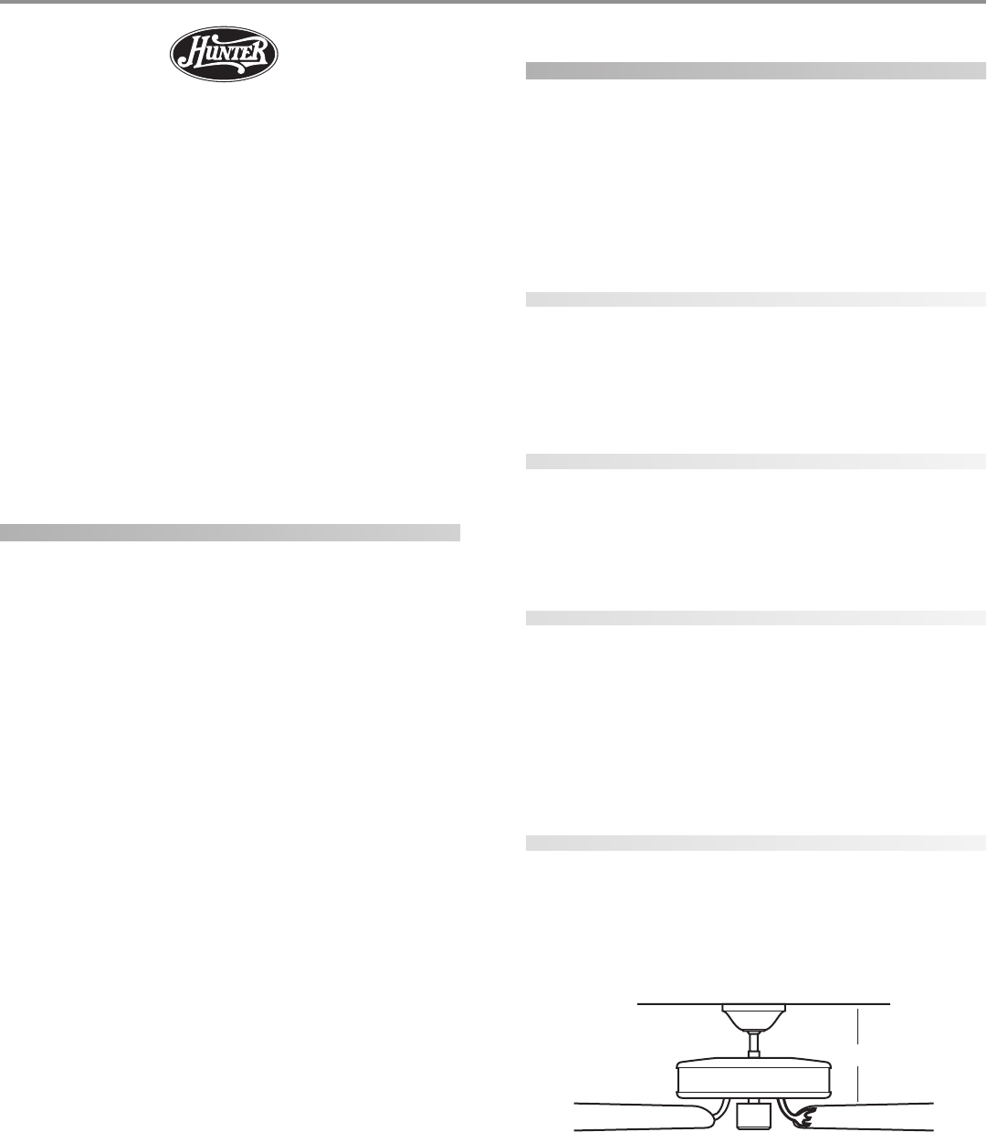
SS
SS
Stt
tt
taa
aa
ann
nn
ndd
dd
daa
aa
arr
rr
rd Md M
d Md M
d Moo
oo
ounun
unun
untt
tt
tinin
inin
ingg
gg
g (Figure 1) hangs from the ceiling by a downrod
(included), for ceilings 9 feet or higher. For ceilings higher than 9
feet, you can purchase Hunter extension downrods. All Hunter
fans use sturdy 3/4" diameter pipe to assure stability and wobble-
free performance.
FF
FF
Fii
ii
igg
gg
gurur
urur
ure 1 - Se 1 - S
e 1 - Se 1 - S
e 1 - Stt
tt
taa
aa
ann
nn
ndd
dd
daa
aa
arr
rr
rd md m
d md m
d moo
oo
ounun
unun
untt
tt
tinin
inin
ingg
gg
g
®
12”
© 2003 Hunter Fan Company 41825-01 02/05/2003
33
33
3
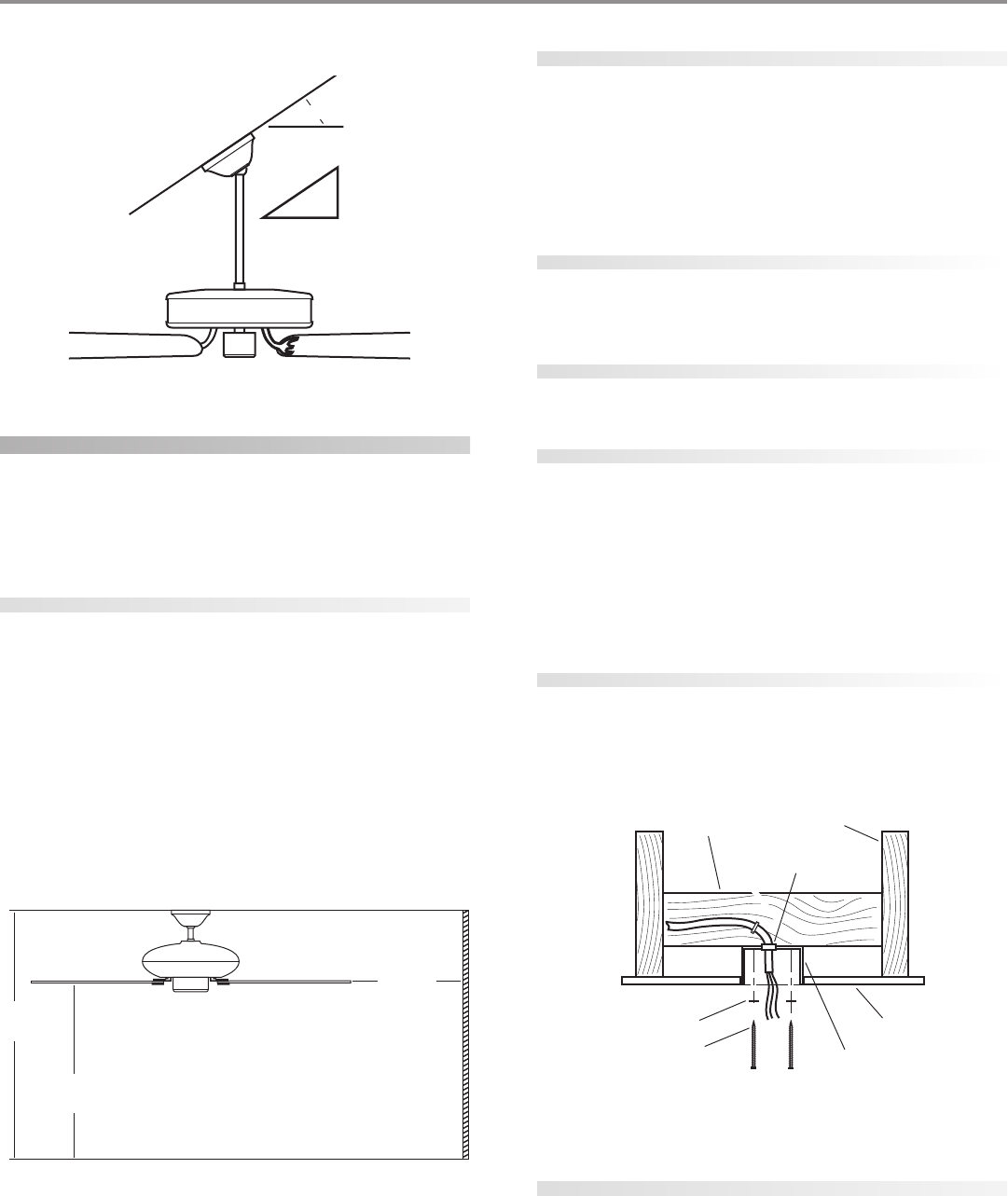
AA
AA
Ann
nn
ngg
gg
gll
ll
le Me M
e Me M
e Moo
oo
ounun
unun
untt
tt
tinin
inin
ingg
gg
g (Figure 2) hangs from a vaulted or angled ceiling.
FF
FF
Fii
ii
igg
gg
gurur
urur
ure 2 - Ae 2 - A
e 2 - Ae 2 - A
e 2 - Ann
nn
ngg
gg
gll
ll
le me m
e me m
e moo
oo
ounun
unun
untt
tt
tinin
inin
ingg
gg
g
preparing the fan site
These guidelines are designed to help you select the best location
for your fan and to prepare the site prior to installing the fan. Proper
ceiling fan location and attachment to the building structure are
essential for safety, reliable operation, maximum efficiency, and en-
ergy savings.
choosing the fan site
Within the room where you want to install the fan, choose a fan
site where:
• No object can come in contact with the rotating fan blades
during normal operation.
• The fan blades are at least 7 feet above the floor and the
ceiling is at least 9 feet high.
• The fan blades have no obstructions to air flow, such as
walls or posts, within 30 inches of the fan blade tips.
• The fan is directly below a joist or support brace that will
hold the outlet box and the full weight of the fan.
See Figure 3 for the minimum mounting distances.
FF
FF
Fii
ii
igg
gg
gurur
urur
ure 3 - Me 3 - M
e 3 - Me 3 - M
e 3 - Minin
inin
inimum mimum m
imum mimum m
imum moo
oo
ounun
unun
untt
tt
tinin
inin
ing dig di
g dig di
g diss
ss
stt
tt
taa
aa
ann
nn
ncc
cc
cee
ee
ess
ss
s
using an existing fan site
If you are preparing a new fan site, go to the pp
pp
prr
rr
ree
ee
epp
pp
paa
aa
arr
rr
rinin
inin
ing a ng a n
g a ng a n
g a nee
ee
ew fw f
w fw f
w faa
aa
ann
nn
n
sisi
sisi
sitt
tt
tee
ee
e section.
If you plan to use an existing fan site, complete the following check-
list for the support brace, ceiling hole, outlet box, and wiring. If you
cannot check off every item, see the pp
pp
prr
rr
ree
ee
epp
pp
paa
aa
arr
rr
rinin
inin
ing a ng a n
g a ng a n
g a nee
ee
ew fw f
w fw f
w faa
aa
an sin si
n sin si
n sitt
tt
tee
ee
e sec-
tion for instructions on properly preparing the site for your new
fan.
fan support system
• Fan must attach directly to building structure.
• Fan support system must hold full weight of fan and light
kit.
ceiling hole
• Outlet box clearance hole directly below the joist or sup-
port brace.
outlet box
• UL-approved octagonal 4" x 1-1/2" outlet box (or as speci-
fied by the support brace manufacturer).
• Outlet box secured to joist or support brace by wood
screws and washers through inner holes of outlet box.
• Outer holes of outlet box aligned with joist or support
brace.
• Bottom of outlet box recessed a minimum of 1/16" into
ceiling.
wiring
• Electrical cable secured to outlet box by approved con-
nector.
• Six inches of lead wires extend from outlet box.
See Figure 4 for an adequate existing fan site.
FF
FF
Fii
ii
igg
gg
gurur
urur
ure 4 - Ae 4 - A
e 4 - Ae 4 - A
e 4 - Add
dd
dee
ee
eqq
qq
quu
uu
uaa
aa
att
tt
te exe ex
e exe ex
e exii
ii
iss
ss
stt
tt
tinin
inin
ing fg f
g fg f
g faa
aa
an sin si
n sin si
n sitt
tt
tee
ee
e
If your existing fan site is suitable, go to the inin
inin
inss
ss
stt
tt
taa
aa
allinllin
llinllin
lling tg t
g tg t
g thh
hh
he ce c
e ce c
e cee
ee
eilinilin
ilinilin
ilingg
gg
g
pp
pp
pll
ll
laa
aa
att
tt
tee
ee
e section and begin installing your new Hunter fan.
preparing a new fan site
To prepare the fan site follow four steps:
• Cutting the Ceiling Hole
• Installing the Support Brace (if necessary)
• Installing the Outlet Box
• Preparing the Wiring
Pitch
12
8
34º Max
9’ Minimum
Ceiling Height
30” From
Wall or
Nearest
Obstruction
7’ Minimum
to Floor
Ceiling Joist
Support Brace
Approved
Connector
Ceiling
Outlet Box
Washer
Wood Screw
41825-01 02/05/2003 © 2003 Hunter Fan Company
44
44
4
cutting the ceiling hole
1. Locate the site for the hole directly below the joist or support
brace that will hold the outlet box and fan.
2. Cut a 4" diameter hole through the drywall or plaster of the
ceiling as shown in Figure 5. You will use the hole to install the
support brace and outlet box.
FF
FF
Fii
ii
igg
gg
gurur
urur
ure 5 - Ce 5 - C
e 5 - Ce 5 - C
e 5 - Cuu
uu
utt
tt
ttt
tt
tinin
inin
ing tg t
g tg t
g thh
hh
he ce c
e ce c
e cee
ee
eilinilin
ilinilin
iling hg h
g hg h
g hoo
oo
oll
ll
lee
ee
e
installing the support brace
If there is a ceiling joist directly above the hole which will allow the
outlet box to be recessed a minimum of 1/16" in the ceiling, go to
inin
inin
inss
ss
stt
tt
taa
aa
allinllin
llinllin
lling tg t
g tg t
g thh
hh
he oe o
e oe o
e ouu
uu
utt
tt
tll
ll
lee
ee
et bt b
t bt b
t boo
oo
oxx
xx
x section.
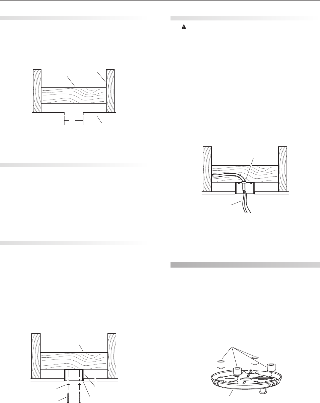
If there is not an adequate ceiling joist available, do the following:
1. Attach a 2" x 4" support brace between two joists. The sup-
port brace must allow the bottom of the outlet box to be re-
cessed a minimum of 1/16" into the ceiling. See Figure 6.
2. Check the support brace to ensure it will support the full weight
of the fan and light kit.
installing the outlet box
1. Obtain a UL-approved octagonal 4" x 1-1/2" outlet box, plus
two #8 x 1-1/2" wood screws and washers, available from any
hardware store or electrical supply house.
2. Orient the outlet box so that both the inner and outer holes in
the box align with the joist or support brace.
3. Drill pilot holes no larger than the minor diameter of the wood
screws (5/64") through the inner holes of the outlet box.
4. Attach the outlet box directly to the support brace or joist
with two #8 x 1-1/2" wood screws and washers. The bottom of
the outlet box must be recessed a minimum of 1/16" into the
ceiling as shown in Figure 6.
FF
FF
Fii
ii
igg
gg
gurur
urur
ure 6 - Ie 6 - I
e 6 - Ie 6 - I
e 6 - Inn
nn
nss
ss
stt
tt
taa
aa
allinllin
llinllin
lling tg t
g tg t
g thh
hh
he oe o
e oe o
e ouu
uu
utt
tt
tll
ll
lee
ee
et bt b
t bt b
t boo
oo
oxx
xx
x
preparing the wiring
CC
CC
CAA
AA
AUU
UU
UTT
TT
TII
II
IOO
OO
ON: AN: A
N: AN: A
N: All wll w
ll wll w
ll wirir
irir
irinin
inin
ing mug mu
g mug mu
g muss
ss
st bt b
t bt b
t be in ae in a
e in ae in a
e in acc
cc
ccc
cc
coo
oo
orr
rr
rdd
dd
daa
aa
ann
nn
ncc
cc
ce we w
e we w
e wii
ii
itt
tt
th nh n
h nh n
h na-a-
a-a-
a-
tt
tt
tii
ii
ioo
oo
onn
nn
naa
aa
al al a
l al a
l ann
nn
nd ld l
d ld l
d loo
oo
occ
cc
caa
aa
al el e
l el e
l ell
ll
lee
ee
ecc
cc
ctt
tt
trr
rr
rii
ii
icc
cc
caa
aa
al cl c
l cl c
l coo
oo
odd
dd
dee
ee
es as a
s as a
s ann
nn
nd Ad A
d Ad A
d ANN
NN
NSS
SS
SI/NI/N
I/NI/N
I/NFF
FF
FPP
PP
PA 70. IA 70. I
A 70. IA 70. I
A 70. If yf y
f yf y
f yoo
oo
ouu
uu
u
aa
aa
arr
rr
re une un
e une un
e unff
ff
faa
aa
amm
mm
miliili
iliili
iliaa
aa
ar wr w
r wr w
r wii
ii
itt
tt
th wh w
h wh w
h wirir
irir
irinin
inin
ingg
gg
g, y, y
, y, y
, yoo
oo
ou su s
u su s
u shh
hh
hoo
oo
oulul
ulul
uld ud u
d ud u
d uss
ss
se a qe a q
e a qe a q
e a quu
uu
uaa
aa
alili
lili
liff
ff
fii
ii
iee
ee
ed ed e
d ed e
d ell
ll
lee
ee
ecc
cc
c--
--
-
tt
tt
trr
rr
rii
ii
icc
cc
cii
ii
iaa
aa
ann
nn
n.....
1. Make sure the circuit breakers to the fan supply line leads and
associated wall switch location are turned off. If you cannot
lock the circuit breakers in the off position, securely fasten a
prominent warning device, such as a tag, to the service panel.
2. Thread the fan supply line through the outlet box so that the
fan supply line extends at least 6" beyond the box as shown in
Figure 7.
3. Attach the fan supply line to the outlet box with an approved
connector, available at any hardware store or electrical supply
house. Refer to Figure 7.
4. Make certain the wiring meets all national and local standards
and ANSI/NFPA 70.
FF
FF
Fii
ii
igg
gg
gurur
urur
ure 7 - Pre 7 - Pr
e 7 - Pre 7 - Pr
e 7 - Pree
ee
epp
pp
paa
aa
arr
rr
rinin
inin
ing tg t
g tg t
g thh
hh
he we w
e we w
e wirir
irir
irinin
inin
ingg
gg
g
You have now successfully prepared your ceiling fan site. For in-
structions on how to install your ceiling fan, continue with the in-in-
in-in-
in-
ss
ss
stt
tt
taa
aa
allinllin
llinllin
lling tg t
g tg t
g thh
hh
he ce c
e ce c
e cee
ee
eilinilin
ilinilin
iling pg p
g pg p
g pll
ll
laa
aa
att
tt
tee
ee
e section.
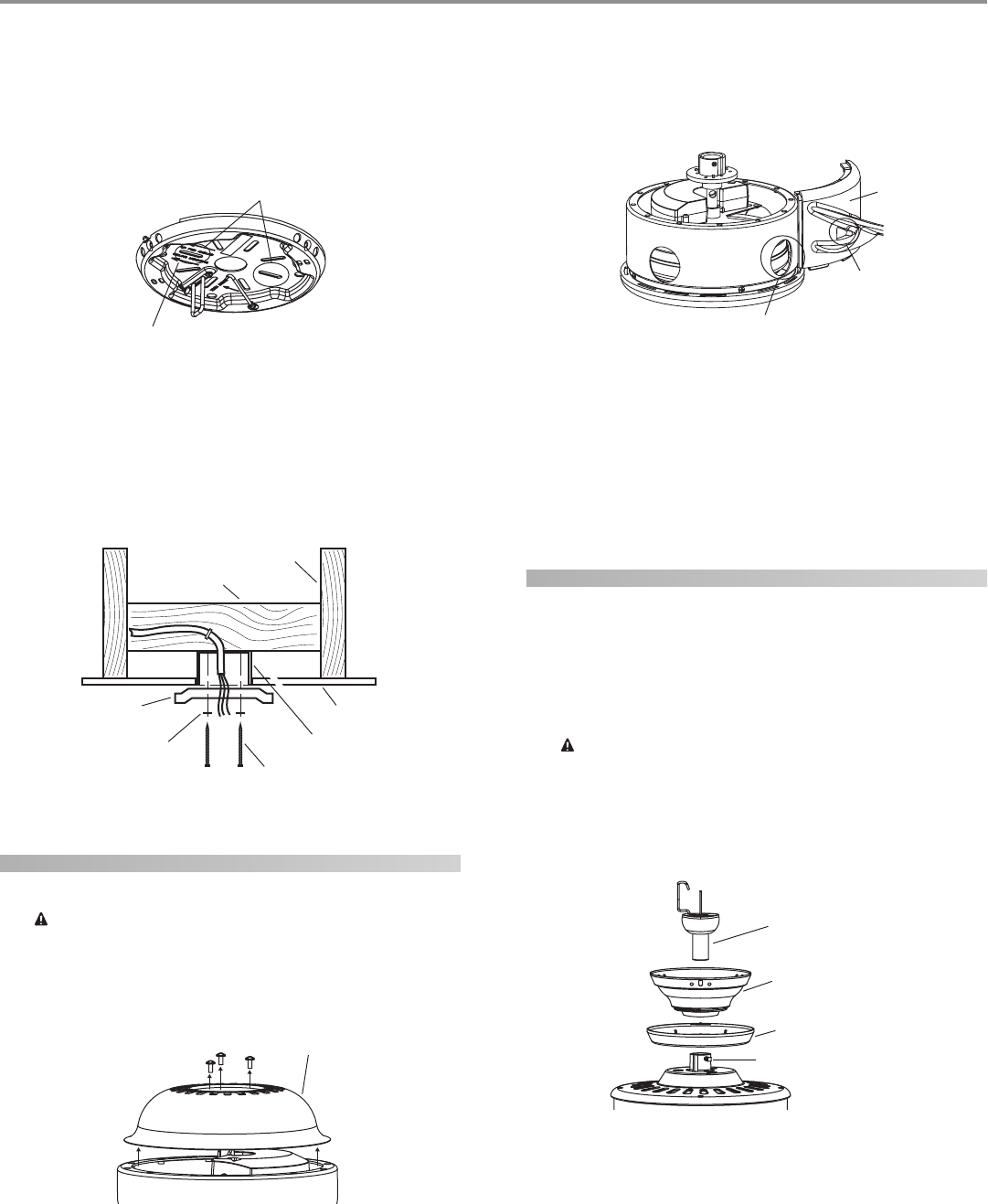
installing the ceiling plate
1. Drill two pilot holes into the wood support structure through
the outermost holes on the outlet box. The pilot holes should
be 9/64" in diameter.
2. Thread the lead wires from the outlet box through the hole in
the middle of the ceiling plate.
3. Your fan comes with four neoprene noise isolators. Position
the isolators between the ceiling plate and ceiling by inserting
the raised areas on each isolator into the holes in the ceiling
plate. Refer to Figure 8.
FF
FF
Fii
ii
igg
gg
gurur
urur
ure 8 - Ie 8 - I
e 8 - Ie 8 - I
e 8 - Inn
nn
nss
ss
see
ee
err
rr
rtt
tt
tinin
inin
ing tg t
g tg t
g thh
hh
he ie i
e ie i
e iss
ss
soo
oo
oll
ll
laa
aa
att
tt
too
oo
orr
rr
rs ins in
s ins in
s intt
tt
to to t
o to t
o thh
hh
he ce c
e ce c
e cee
ee
eilinilin
ilinilin
iling pg p
g pg p
g pll
ll
laa
aa
att
tt
tee
ee
e
4”
Diameter
Ceiling
Hole
Ceiling
Ceiling Joist
Support Brace
Support Brace
Outlet Box
1/16” Recess
Washer
Wood Screw
Approved
Connector
Wire Leads
Isolators
Ceiling Plate
© 2003 Hunter Fan Company 41825-01 02/05/2003
55
55
5
4. Align the slotted holes (refer to Figure 10) in the ceiling plate
with the pilot holes in the wood support structure. Note: The
isolation pads should be flush against the ceiling.
For Angled Ceilings: Be sure to orient the ceiling plate so that
the arrows on the ceiling plate are pointing towards the ceiling
peak. Refer to Figure 9.
FF
FF
Fii
ii
igg
gg
gurur
urur
ure 9 - Le 9 - L
e 9 - Le 9 - L
e 9 - Loo
oo
occ
cc
caa
aa
att
tt
tinin
inin
ing tg t
g tg t
g thh
hh
he se s
e se s
e sll
ll
loo
oo
ott
tt
ttt
tt
tee
ee
ed hd h
d hd h
d hoo
oo
oll
ll
lee
ee
es ts t
s ts t
s to uo u
o uo u
o uss
ss
see
ee
e
5. Place a flat washer on each of the two 3" screws and pass the
screws through the slotted holes in the ceiling plate as shown
in Figure 10.
6. Tighten the screws into the 9/64" pilot holes; do not use lubri-
cants on the screws. Do not overtighten.
FF
FF
Fii
ii
igg
gg
gurur
urur
ure 10 - Ie 10 - I
e 10 - Ie 10 - I
e 10 - Inn
nn
nss
ss
stt
tt
taa
aa
allinllin
llinllin
lling tg t
g tg t
g thh
hh
he ce c
e ce c
e cee
ee
eilinilin
ilinilin
iling pg p
g pg p
g pll
ll
laa
aa
att
tt
tee
ee
e
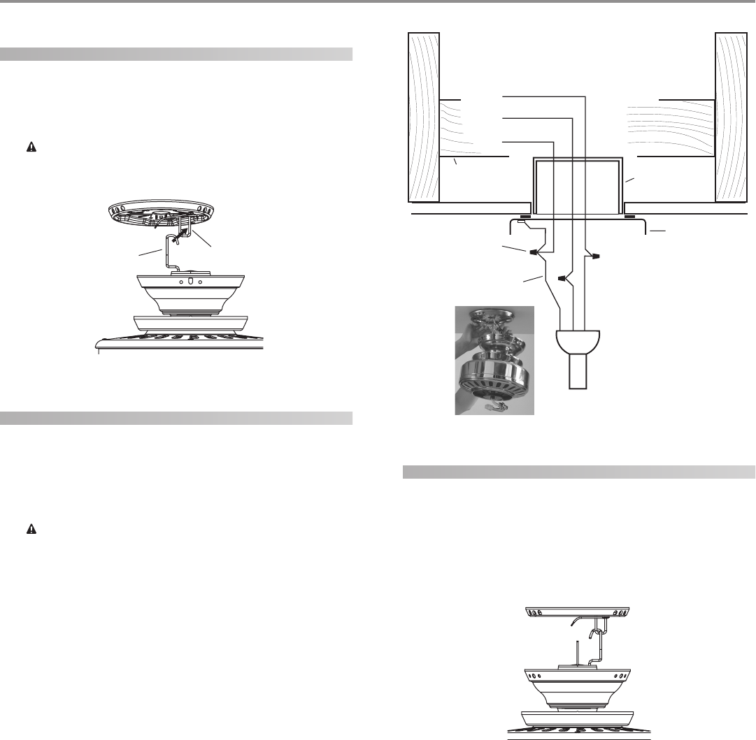
assembling the blades
1. Rest the fan on the package.
CC
CC
CAA
AA
AUU
UU
UTT
TT
TII
II
IOO
OO
ON: DN: D
N: DN: D
N: Do no n
o no n
o noo
oo
ot pt p
t pt p
t pinin
inin
incc
cc
ch wh w
h wh w
h wirir
irir
iree
ee
es cs c
s cs c
s coo
oo
omm
mm
minin
inin
ing fg f
g fg f
g frr
rr
roo
oo
om tm t
m tm t
m thh
hh
he be b
e be b
e boo
oo
ott
tt
t--
--
-
tt
tt
too
oo
om om o
m om o
m of tf t
f tf t
f thh
hh
he ce c
e ce c
e cee
ee
eilinilin
ilinilin
iling fg f
g fg f
g faa
aa
ann
nn
n.....
2. Remove the three screws, then remove the upper motor hous-
ing as shown in Figure 11.
FF
FF
Fii
ii
igg
gg
gurur
urur
ure 11 - Re 11 - R
e 11 - Re 11 - R
e 11 - Ree
ee
emm
mm
moo
oo
ovv
vv
vinin
inin
ing tg t
g tg t
g thh
hh
he upe up
e upe up
e uppp
pp
pee
ee
er mr m
r mr m
r moo
oo
ott
tt
too
oo
or hr h
r hr h
r hoo
oo
ouu
uu
usinsin
sinsin
singg
gg
g
3. Assemble a blade as shown in Figure 12.
NOTE: The hole on the bracket part of the blade should align
with one of the large holes on the motor housing.
FF
FF
Fii
ii
igg
gg
gurur
urur
ure 12 - Ae 12 - A
e 12 - Ae 12 - A
e 12 - Ass
ss
sss
ss
see
ee
embmb
mbmb
mblinlin
linlin
ling tg t
g tg t
g thh
hh
he be b
e be b
e bll
ll
laa
aa
add
dd
dee
ee
ess
ss
s
4. Install the three blade assembly screws loosely.
5. Repeat steps 3 and 4 for each blade until all four blades are
assembled.
6. Securely tighten all blade assembly screws.
7. Reassemble the upper motor housing with the previously re-
moved screws.
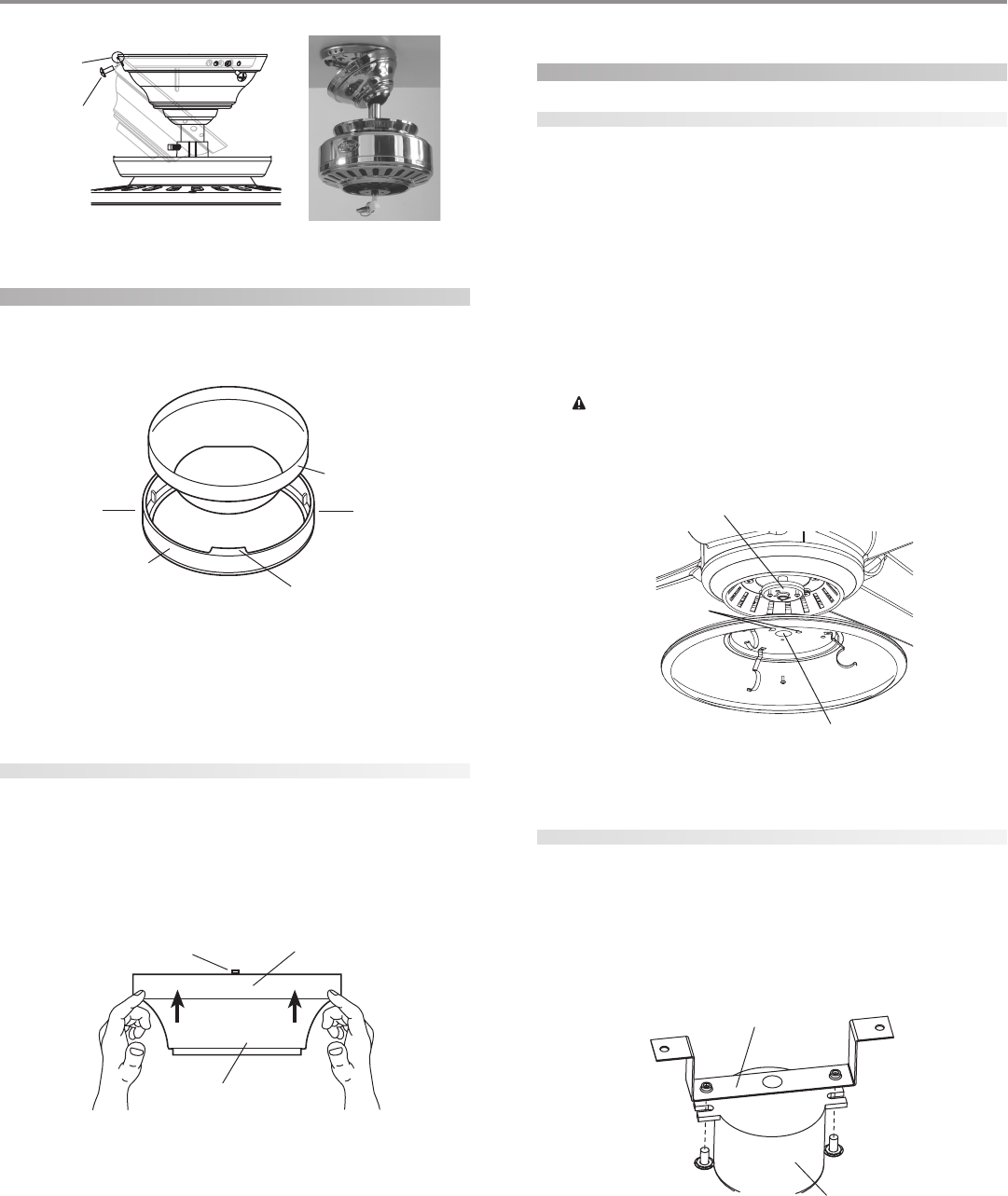
assembling the fan
1. Insert the downrod through the canopy and canopy trim ring
as shown in Figure 13. Feed wires from the fan through the
downrod.
2. Screw the downrod into the fan assembly until tight. IMPOR-
TANT! Tighten allen head set screw as shown in Figure 13 with
the included allen wrench.
CC
CC
CAA
AA
AUU
UU
UTT
TT
TII
II
IOO
OO
ON: TN: T
N: TN: T
N: Thh
hh
he de d
e de d
e doo
oo
oww
ww
wnrnr
nrnr
nroo
oo
od hd h
d hd h
d haa
aa
as a ss a s
s a ss a s
s a spp
pp
pee
ee
ecc
cc
cii
ii
iaa
aa
al cl c
l cl c
l coo
oo
oaa
aa
att
tt
tinin
inin
ing og o
g og o
g on tn t
n tn t
n thh
hh
hee
ee
e
tt
tt
thrhr
hrhr
hree
ee
eaa
aa
add
dd
dss
ss
s. D. D
. D. D
. Do no n
o no n
o noo
oo
ot rt r
t rt r
t ree
ee
emm
mm
moo
oo
ovv
vv
ve te t
e te t
e thh
hh
hii
ii
is cs c
s cs c
s coo
oo
oaa
aa
att
tt
tinin
inin
ing; tg; t
g; tg; t
g; thh
hh
he ce c
e ce c
e coo
oo
oaa
aa
att
tt
tinin
inin
ing pg p
g pg p
g prr
rr
ree
ee
evv
vv
vee
ee
enn
nn
ntt
tt
tss
ss
s
tt
tt
thh
hh
he de d
e de d
e doo
oo
oww
ww
wnrnr
nrnr
nroo
oo
od fd f
d fd f
d frr
rr
roo
oo
om unm un
m unm un
m unss
ss
scc
cc
crr
rr
ree
ee
eww
ww
winin
inin
ingg
gg
g. O. O
. O. O
. Onn
nn
ncc
cc
ce ae a
e ae a
e ass
ss
sss
ss
see
ee
embmb
mbmb
mbll
ll
lee
ee
ed, dd, d
d, dd, d
d, do no n
o no n
o noo
oo
ott
tt
t
rr
rr
ree
ee
emm
mm
moo
oo
ovv
vv
ve te t
e te t
e thh
hh
he de d
e de d
e doo
oo
oww
ww
wnrnr
nrnr
nroo
oo
od.d.
d.d.
d.
3. Continue to the hh
hh
haa
aa
ann
nn
ngg
gg
ginin
inin
ing tg t
g tg t
g thh
hh
he fe f
e fe f
e faa
aa
ann
nn
n section.
FF
FF
Fii
ii
igg
gg
gurur
urur
ure 13 - Ae 13 - A
e 13 - Ae 13 - A
e 13 - Ass
ss
sss
ss
see
ee
embmb
mbmb
mblinlin
linlin
ling tg t
g tg t
g thh
hh
he de d
e de d
e doo
oo
oww
ww
wnrnr
nrnr
nroo
oo
odd
dd
d
Slots
Arrows for Orienting
on Angled Ceiling
Ceiling Joist
2 x 4 Brace
Ceiling
Ceiling Plate
Flat Washer Outlet Box
3” Wood Screw
Hanger Ball/
Downrod Assembly
Canopy
Canopy Trim Ring
Allen Head Pipe Set Screw
Upper Motor
Housing
Blade
Hole on the
Bracket of
the Blade
Large Hole on the
Motor Housing
41825-01 02/05/2003 © 2003 Hunter Fan Company
66
66
6
hanging the fan
1. Raise the fan and place the hook through the loop on the ceil-
ing plate as shown in Figure 14. Use the note and arrow en-
graved in the ceiling plate to assist in determining the direc-
tion to assemble.
WW
WW
WAA
AA
ARR
RR
RNN
NN
NII
II
INN
NN
NG: FG: F
G: FG: F
G: Faa
aa
an mn m
n mn m
n maa
aa
ay fy f
y fy f
y faa
aa
all ill i
ll ill i
ll if nf n
f nf n
f noo
oo
ot at a
t at a
t ass
ss
sss
ss
see
ee
embmb
mbmb
mbll
ll
lee
ee
ed ad a
d ad a
d as dirs dir
s dirs dir
s diree
ee
ecc
cc
ctt
tt
tee
ee
ed ind in
d ind in
d in
tt
tt
thh
hh
hee
ee
ess
ss
se ine in
e ine in
e inss
ss
stt
tt
taa
aa
allll
llll
llaa
aa
att
tt
tii
ii
ioo
oo
on inn in
n inn in
n inss
ss
stt
tt
trr
rr
ruu
uu
ucc
cc
ctt
tt
tii
ii
ioo
oo
onn
nn
nss
ss
s.....
FF
FF
Fii
ii
igg
gg
gurur
urur
ure 14 - Hae 14 - Ha
e 14 - Hae 14 - Ha
e 14 - Hann
nn
ngg
gg
ginin
inin
ing tg t
g tg t
g thh
hh
he fe f
e fe f
e faa
aa
ann
nn
n
wiring the fan
1. Disconnect the power by turning off the circuit breakers to
the outlet box and associated wall switch location.
2. Connect the wires as shown in Figure 15. To connect the wires,
twist the bare metal leads together. Place a wire nut over the
intertwined length of wire and twist clockwise until tight as.
CC
CC
CAA
AA
AUU
UU
UTT
TT
TII
II
IOO
OO
ON: BN: B
N: BN: B
N: Be se s
e se s
e surur
urur
ure ne n
e ne n
e no bo b
o bo b
o baa
aa
arr
rr
re we w
e we w
e wirir
irir
ire oe o
e oe o
e or wr w
r wr w
r wirir
irir
ire se s
e se s
e stt
tt
trr
rr
raa
aa
ann
nn
ndd
dd
ds as a
s as a
s arr
rr
re ve v
e ve v
e vii
ii
iss
ss
s--
--
-
ibib
ibib
ibll
ll
le ae a
e ae a
e aff
ff
ftt
tt
tee
ee
er mr m
r mr m
r maa
aa
akk
kk
kinin
inin
ing cg c
g cg c
g coo
oo
onnnn
nnnn
nnee
ee
ecc
cc
ctt
tt
tii
ii
ioo
oo
onn
nn
nss
ss
s.....
AA
AA
All wll w
ll wll w
ll wirir
irir
irinin
inin
ing mug mu
g mug mu
g muss
ss
st bt b
t bt b
t be in ae in a
e in ae in a
e in acc
cc
ccc
cc
coo
oo
orr
rr
rdd
dd
daa
aa
ann
nn
ncc
cc
ce we w
e we w
e wii
ii
itt
tt
th nh n
h nh n
h naa
aa
att
tt
tii
ii
ioo
oo
onn
nn
naa
aa
al al a
l al a
l ann
nn
nd ld l
d ld l
d loo
oo
occ
cc
caa
aa
all
ll
l
ee
ee
ell
ll
lee
ee
ecc
cc
ctt
tt
trr
rr
rii
ii
icc
cc
caa
aa
al cl c
l cl c
l coo
oo
odd
dd
dee
ee
es as a
s as a
s ann
nn
nd Ad A
d Ad A
d ANN
NN
NSS
SS
SI/NI/N
I/NI/N
I/NFF
FF
FPP
PP
PA 70. IA 70. I
A 70. IA 70. I
A 70. If yf y
f yf y
f yoo
oo
ou au a
u au a
u arr
rr
re une un
e une un
e unff
ff
faa
aa
amm
mm
miliili
iliili
iliaa
aa
arr
rr
r
ww
ww
wii
ii
itt
tt
th wh w
h wh w
h wirir
irir
irinin
inin
ingg
gg
g, y, y
, y, y
, yoo
oo
ou su s
u su s
u shh
hh
hoo
oo
oulul
ulul
uld ud u
d ud u
d uss
ss
se a qe a q
e a qe a q
e a quu
uu
uaa
aa
alili
lili
liff
ff
fii
ii
iee
ee
ed ed e
d ed e
d ell
ll
lee
ee
ecc
cc
ctt
tt
trr
rr
rii
ii
icc
cc
cii
ii
iaa
aa
ann
nn
n.....
FF
FF
Fii
ii
igg
gg
gurur
urur
ure 15 - We 15 - W
e 15 - We 15 - W
e 15 - Wirir
irir
irinin
inin
ing tg t
g tg t
g thh
hh
he fe f
e fe f
e faa
aa
ann
nn
n
installing the canopy
1. Rotate the fan 180º clockwise from the initial position when
hanging the fan. The arrows on the hanger ball and on the
ceiling plate should be pointing in the same direction and
should be pointing towards the tab hole on the canopy. Refer
to Figure 16.
FF
FF
Fii
ii
igg
gg
gurur
urur
ure 16 - Re 16 - R
e 16 - Re 16 - R
e 16 - Roo
oo
ott
tt
taa
aa
att
tt
tinin
inin
ing tg t
g tg t
g thh
hh
he fe f
e fe f
e faa
aa
ann
nn
n
For Flush Mounting: The arrows on the low profile washer and
on the ceiling plate should be pointing in the same direction
and should be pointing towards the tab hole on the canopy.
2. Hook the tab hole over the tab on the ceiling plate as shown in
Figure 17.
3. Raise the canopy, be sure the holes in the canopy and the ceil-
ing plate are aligned, and loosely assemble the canopy screws
one at a time. When all three screws are assembled, securely
tighten all three canopy screws. Refer to Figure 17.
Hook Loop
Power
Wires
in
Ceiling
Black
White
Bare or Green
2 x 4 Brace Outlet Box
Ceiling Plate
Approved
Connectors
Green Ground Wire from
Hanger Pipe (not present
with flush mounting
option)
White
Black
© 2003 Hunter Fan Company 41825-01 02/05/2003
77
77
7
FF
FF
Fii
ii
igg
gg
gurur
urur
ure 17 - Ie 17 - I
e 17 - Ie 17 - I
e 17 - Inn
nn
nss
ss
stt
tt
taa
aa
allinllin
llinllin
lling tg t
g tg t
g thh
hh
he ce c
e ce c
e caa
aa
ann
nn
noo
oo
opp
pp
pyy
yy
y
installing the canopy trim ring
1. To easily install the canopy trim ring, locate the two tabs on
the canopy trim ring. See Figure 18.
FF
FF
Fii
ii
igg
gg
gurur
urur
ure 18 - Ce 18 - C
e 18 - Ce 18 - C
e 18 - Caa
aa
ann
nn
noo
oo
opp
pp
py ty t
y ty t
y trr
rr
rim rim r
im rim r
im rinin
inin
ingg
gg
g
2. Take both hands and push the canopy trim ring up to the top
of the canopy. See Figure 18.
3. The canopy trim ring will snap and lock into place on the
canopy.
removing the canopy trim ring
1. Locate the tab indicators, small bumps on top of tabs. Refer to
Figure 19.
2. To remove the canopy trim ring, press firmly on opposite sides
of the ring towards the canopy as shown in Figure 19. The tabs
will flex out releasing the trim ring from the canopy.
FF
FF
Fii
ii
igg
gg
gurur
urur
ure 19 - Re 19 - R
e 19 - Re 19 - R
e 19 - Ree
ee
emm
mm
moo
oo
ovv
vv
vinin
inin
ing tg t
g tg t
g thh
hh
he ce c
e ce c
e caa
aa
ann
nn
noo
oo
opp
pp
py ty t
y ty t
y trr
rr
rim rim r
im rim r
im rinin
inin
ingg
gg
g
installing the light fixture
attaching the light fitter
1. Partially install two #6-32 x 3/8" assembly screws into the
mounting plate as shown in Figure 20.
2. Feed the two plug connectors from the fan body through the
center hole of the light fitter.
3. Align the keyhole slots in the light fitter with the assembly
screws installed previously.
4. Turn the light fitter counterclockwise until the assembly screws
are firmly situated in the narrow end of the keyhole slots as
shown in Figure 20. Install the one remaining #6-32 x 3/8" as-
sembly screw into the third hole in the light fitter. Tighten all
three screws firmly.
CC
CC
CAA
AA
AUU
UU
UTT
TT
TII
II
IOO
OO
ON: MN: M
N: MN: M
N: Maa
aa
akk
kk
ke se s
e se s
e surur
urur
ure te t
e te t
e thh
hh
he lie li
e lie li
e ligg
gg
ghh
hh
ht ft f
t ft f
t fii
ii
itt
tt
ttt
tt
tee
ee
er ir i
r ir i
r is ss s
s ss s
s see
ee
ecc
cc
curur
urur
uree
ee
ell
ll
ly ay a
y ay a
y att
tt
ttt
tt
taa
aa
acc
cc
chh
hh
hee
ee
edd
dd
d
tt
tt
to to t
o to t
o thh
hh
he me m
e me m
e moo
oo
ounun
unun
untt
tt
tinin
inin
ing pg p
g pg p
g pll
ll
laa
aa
att
tt
tee
ee
e. F. F
. F. F
. Faa
aa
ailurilur
ilurilur
ilure te t
e te t
e to po p
o po p
o prr
rr
roo
oo
opp
pp
pee
ee
err
rr
rll
ll
ly ay a
y ay a
y att
tt
ttt
tt
taa
aa
acc
cc
ch ah a
h ah a
h ann
nn
ndd
dd
d
tt
tt
tii
ii
igg
gg
ghh
hh
htt
tt
tee
ee
en an a
n an a
n all tll t
ll tll t
ll thrhr
hrhr
hree
ee
ee ae a
e ae a
e ass
ss
sss
ss
see
ee
embmb
mbmb
mbll
ll
ly sy s
y sy s
y scc
cc
crr
rr
ree
ee
eww
ww
ws cs c
s cs c
s coo
oo
oulul
ulul
uld rd r
d rd r
d ree
ee
ess
ss
sulul
ulul
ult in tt in t
t in tt in t
t in thh
hh
he lie li
e lie li
e ligg
gg
ghh
hh
htt
tt
t
ff
ff
fii
ii
ixx
xx
xtt
tt
turur
urur
ure fe f
e fe f
e faa
aa
allinllin
llinllin
llingg
gg
g.....
FF
FF
Fii
ii
igg
gg
gurur
urur
ure 20 - Ae 20 - A
e 20 - Ae 20 - A
e 20 - Att
tt
ttt
tt
taa
aa
acc
cc
chh
hh
hinin
inin
ing tg t
g tg t
g thh
hh
he lie li
e lie li
e ligg
gg
ghh
hh
ht ft f
t ft f
t fii
ii
itt
tt
ttt
tt
tee
ee
err
rr
r
attaching the glass globe
1. Feed the two plug connectors -- female plug first then male
plug -- from the ballast through the center hole of the smaller
of the two rectangular metal brackets. Refer to Figure 21.
2. Attach the metal bracket to the ballast with two #10-32 x 3/8”
screws as shown in Figure 21.
FF
FF
Fii
ii
igg
gg
gurur
urur
ure 21 - Ae 21 - A
e 21 - Ae 21 - A
e 21 - Att
tt
ttt
tt
taa
aa
acc
cc
chh
hh
hinin
inin
ing tg t
g tg t
g thh
hh
he be b
e be b
e brr
rr
raa
aa
acc
cc
ckk
kk
kee
ee
et tt t
t tt t
t to to t
o to t
o thh
hh
he be b
e be b
e baa
aa
allll
llll
llaa
aa
ass
ss
stt
tt
t
Canopy
Canopy
Trim Ring Tab
Press Here when
Removing
Press Here when
Removing
Canopy Trim Ring
Canopy
Tab Indicator
Tab Hole
and Tab
Canopy
Screw
Mounting Plate
Center Hole of
the Light Fitter
Keyhole Slots
Smaller Rectangular
Metal Bracket
Ballast
41825-01 02/05/2003 © 2003 Hunter Fan Company
88
88
8
3. Align the screw holes in the larger metal bracket with the screws
holes in the smaller metal bracket and the light fitter as shown
in Figure 22.
4. Install two #10-32 x 3/8” screws.
FF
FF
Fii
ii
igg
gg
gurur
urur
ure 22 - Ae 22 - A
e 22 - Ae 22 - A
e 22 - Att
tt
ttt
tt
taa
aa
acc
cc
chh
hh
hinin
inin
ing tg t
g tg t
g thh
hh
he be b
e be b
e brr
rr
raa
aa
acc
cc
ckk
kk
kee
ee
ett
tt
ts ts t
s ts t
s to to t
o to t
o thh
hh
he lie li
e lie li
e ligg
gg
ghh
hh
ht ft f
t ft f
t fii
ii
itt
tt
ttt
tt
tee
ee
err
rr
r
5. Install the included bulb. Connect the plug connector from
the ballast to the bulb.
6. Align and install the glass globe to the light fitter.
7. Twist clockwise and tighten the finial.
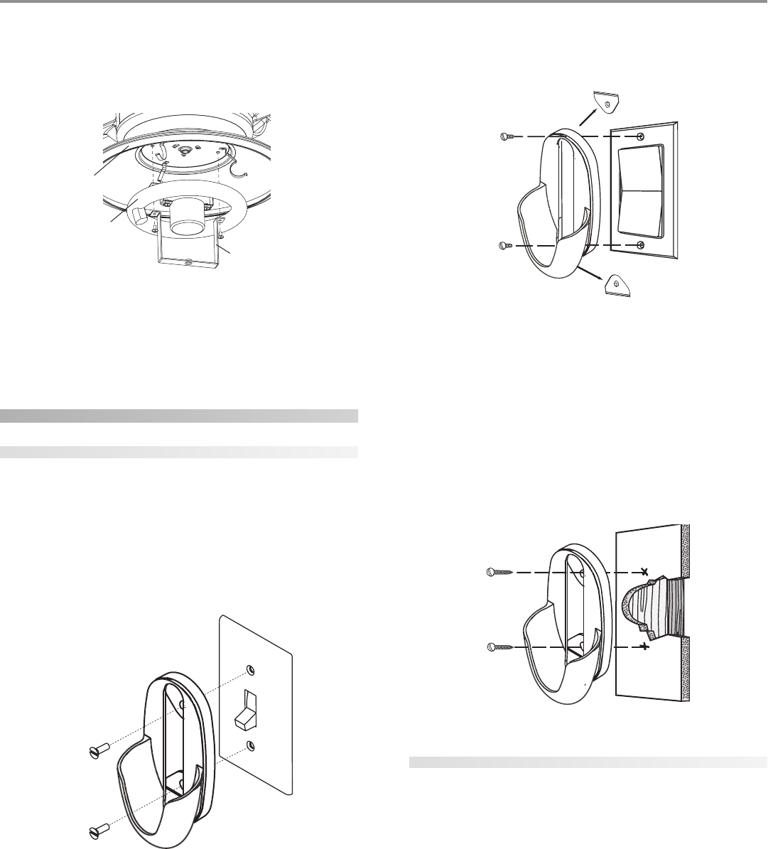
setting up your remote
installing the remote cradle
standard light switch
1. Remove the two screws holding the switch cover plate. Do not
remove the cover plate.
2. Orient the control cradle as shown in Figure 23, and line up
the two inner mounting holes with those on the switch, insert
screws, don't over tighten.
FF
FF
Fii
ii
igg
gg
gurur
urur
ure 23 - Ie 23 - I
e 23 - Ie 23 - I
e 23 - Inn
nn
nss
ss
stt
tt
taa
aa
allinllin
llinllin
lling tg t
g tg t
g thh
hh
he re r
e re r
e ree
ee
emm
mm
moo
oo
ott
tt
te ce c
e ce c
e crr
rr
raa
aa
add
dd
dll
ll
le fe f
e fe f
e foo
oo
or a sr a s
r a sr a s
r a stt
tt
taa
aa
ann
nn
ndd
dd
daa
aa
arr
rr
rd lid li
d lid li
d ligg
gg
ghh
hh
htt
tt
t
ss
ss
sww
ww
wii
ii
itt
tt
tcc
cc
chh
hh
h
rocker light switch
1. Break off the two tabs by pushing outward. See Figure 24.
2. Remove the two screws holding the switch cover plate. Do not
remove the cover plate.
3. Orient the remote cradle as shown in Figure 24. Line up the
two outer mounting holes with those on the switch , insert
screws, don't over tighten.
FF
FF
Fii
ii
igg
gg
gurur
urur
ure 24 - Ie 24 - I
e 24 - Ie 24 - I
e 24 - Inn
nn
nss
ss
stt
tt
taa
aa
allinllin
llinllin
lling tg t
g tg t
g thh
hh
he re r
e re r
e ree
ee
emm
mm
moo
oo
ott
tt
te ce c
e ce c
e crr
rr
raa
aa
add
dd
dll
ll
le fe f
e fe f
e foo
oo
or a rr a r
r a rr a r
r a roo
oo
occ
cc
ckk
kk
kee
ee
er lir li
r lir li
r ligg
gg
ghh
hh
htt
tt
t
ss
ss
sww
ww
wii
ii
itt
tt
tcc
cc
chh
hh
h
wall installation
1. Locate a 2x4 wall stud in a convenient location.
2. Orient the remote cradle as shown in Figure 25, over the 2x4
stud.
3. Use the 1” wood screws in either the inner or outer mounting
holes.
NOTE: Wall anchors and 6-32 x 1” screws may be used in situ-
ations where mounting to a stud is not possible. Use the inner
mounting holes.
FF
FF
Fii
ii
igg
gg
gurur
urur
ure 25 - Ie 25 - I
e 25 - Ie 25 - I
e 25 - Inn
nn
nss
ss
stt
tt
taa
aa
allinllin
llinllin
lling tg t
g tg t
g thh
hh
he re r
e re r
e ree
ee
emm
mm
moo
oo
ott
tt
te ce c
e ce c
e crr
rr
raa
aa
add
dd
dll
ll
le oe o
e oe o
e on tn t
n tn t
n thh
hh
he we w
e we w
e waa
aa
allll
llll
ll
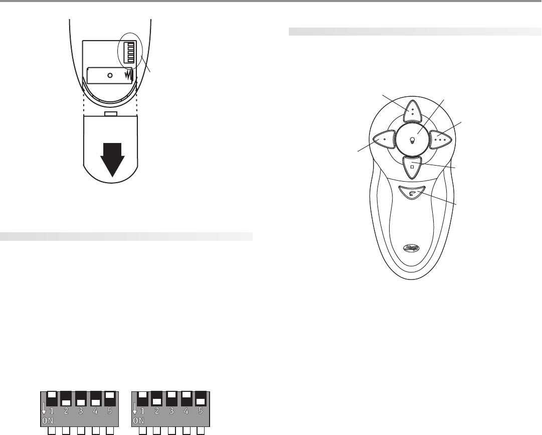
installing the battery
1. Slide the cover off the back of the remote as shown in Figure
26, pressing in and sliding the cover down to release.
2. Install the included 12 volt alkaline battery (Type 23A, MN-21
or equivalent) inside the remote, matching polarity on the Bat-
tery as indicated by the + and - symbols in the Battery Com-
partment. See Figure 26. Replace the cover.
Larger Metal
Bracket
Light
Fitter
Bulb
© 2003 Hunter Fan Company 41825-01 02/05/2003
99
99
9
FF
FF
Fii
ii
igg
gg
gurur
urur
ure 26 - Ie 26 - I
e 26 - Ie 26 - I
e 26 - Inn
nn
nss
ss
stt
tt
taa
aa
allinllin
llinllin
lling tg t
g tg t
g thh
hh
he be b
e be b
e baa
aa
att
tt
ttt
tt
tee
ee
err
rr
ry ay a
y ay a
y ann
nn
nd sd s
d sd s
d see
ee
ett
tt
ttt
tt
tinin
inin
ing tg t
g tg t
g thh
hh
he dipe dip
e dipe dip
e dip
ss
ss
sww
ww
wii
ii
itt
tt
tcc
cc
chh
hh
hee
ee
ess
ss
s
setting the dip switches
NOTE: You will only have to change the DIP switch settings in the
remote if you are using more than one remote controlled fan in the
same area and want to control them separately.
1. At the circuit breaker or fuse box, turn the power off for the
fan you want to change.
2. Slide the cover off the back of the remote and remove the bat-
tery. The battery must be removed when changing dip switch
settings. Refer to BATTERY INSTALLATION and Figure 26.
3. Change the DIP switch settings, assuring that they are differ-
ent from the previously installed fan. Refer to Figure 27.
FF
FF
Fii
ii
igg
gg
gurur
urur
ure 27 - Se 27 - S
e 27 - Se 27 - S
e 27 - See
ee
ett
tt
ttt
tt
tinin
inin
ing tg t
g tg t
g thh
hh
he dip se dip s
e dip se dip s
e dip sww
ww
wii
ii
itt
tt
tcc
cc
chh
hh
hee
ee
ess
ss
s
4. Replace the battery and cover.
5. At the circuit breaker or fuse box, turn the power back on for
the fan whose settings you are changing.
6. Within 20 seconds of restoring power, push the Hi, Med, and
Lo buttons (in that order). Refer to Figure 28.
NOTE: You may want to label your controls to assure you do
not mix them up.
Do not turn the power off at the circuit breaker, then back on,
for the previously installed fan(s), as you may inadvertently
change the DIP switch code settings for it as well.
NOTE: The DIP SWITCH SETTING sub steps must be repeated
as described above for the proper setting of the DIP switch
code in the receiver and remote.
power failure
The receiver has a memory function that retains the last DIP switch
code setting. The setting will not change in the event of power
failure or if power to the fan is inadvertently shut off.
using the remote control
fan control
Refer to Figure 28 for identification of control buttons.
FF
FF
Fii
ii
igg
gg
gurur
urur
ure 28 - Usine 28 - Usin
e 28 - Usine 28 - Usin
e 28 - Using tg t
g tg t
g thh
hh
he re r
e re r
e ree
ee
emm
mm
moo
oo
ott
tt
te ce c
e ce c
e coo
oo
onn
nn
ntt
tt
trr
rr
roo
oo
oll
ll
l
To start the fan press the selected speed button to run the fan at
the desired speed.
To turn off the fan. Press the FAN OFF button.
airflow direction
To reverse the airflow press the REVERSE button. Reverse operates
at any speed whether fan is on or off. The fan returns to its set speed
after reversing.
If the fan is not functioning after installation:
1. Check to make sure that battery is installed correctly in the
control.
2. Turn the power off to the fan (from the circuit breaker) for at
least 5 seconds.
3. Turn the power back on (at the circuit breaker) and push the
Hi, Med, and Low buttons–in that order–within 20 seconds.
4. The fan should now function properly.
light control
Turn the light on or off independently from the fan by pressing the
LIGHT button. When the light is on, press the LIGHT button 1 time
for a gradual off (light dims from full brightness to completely off)
or press the LIGHT button 2 times for an instant off.
Press the button for longer than 1 second, it becomes a dimmer.
The light varies from ‘bright’ to ‘dim’ over approximately 8 seconds.
This sequence will reverse the light when it reaches the brightest or
dimmest level if you continue to hold the LIGHT button. Release
the button when the desired level is reached.
auto resume
Quick (pressing less than 1 second) on/off operation of the LIGHT
button maintains the desired brightness level set previously.
Dip Switches
Fan Low
Fan Medium
Fan High
Fan Off
Reverse
Light
41825-01 02/05/2003 © 2003 Hunter Fan Company
1010
1010
10
FCC information
1. This device complies with Part 15 of the FCC Rules. Operation
is subject to the following two conditions: (1) This device may
not cause harmful interference, and (2) this device must ac-
cept any interference received, including interference that may
cause undesired operation.
2. This equipment has been tested and found to comply with the
limits for a Class B digital device, pursuant to Part 15 of the
FCC Rules.
These limits are designed to provide reasonable protection
against harmful interference in a residential installation. This
equipment generates, uses and can radiate radio frequency
energy and, if not installed and used in accordance with the
instructions, may cause harmful interference to radio commu-
nications. However, there is no guarantee that interference will
not occur in a particular installation.
If this equipment does cause harmful interference to radio or
television reception, which can be determined by turning the
equipment off and on, the user is encouraged to try to correct
the interference by one or more of the following measures:
• Reorient or relocate the receiving antenna.
• Increase the separation between the equipment and re-
ceiver.
• Connect the equipment into an outlet on a circuit differ-
ent from that to which the receiver is connected.
• Consult the dealer or an experienced radio/TV technician
for help.
NOTE: Any changes or modifications to the transmitter or re-
ceiver not expressly approved by Hunter Fan Company may
void one’s authority to operate this remote control.
3. For use only with electrically reversible ceiling fans rated at 1.0
amp or less, and fan incandescent light kits rated at 300 watts
or less.
4. Not for use with shaded-pole or nonreversible motors. Not
recommended for use with the Hunter Original ®.
operating your ceiling fan
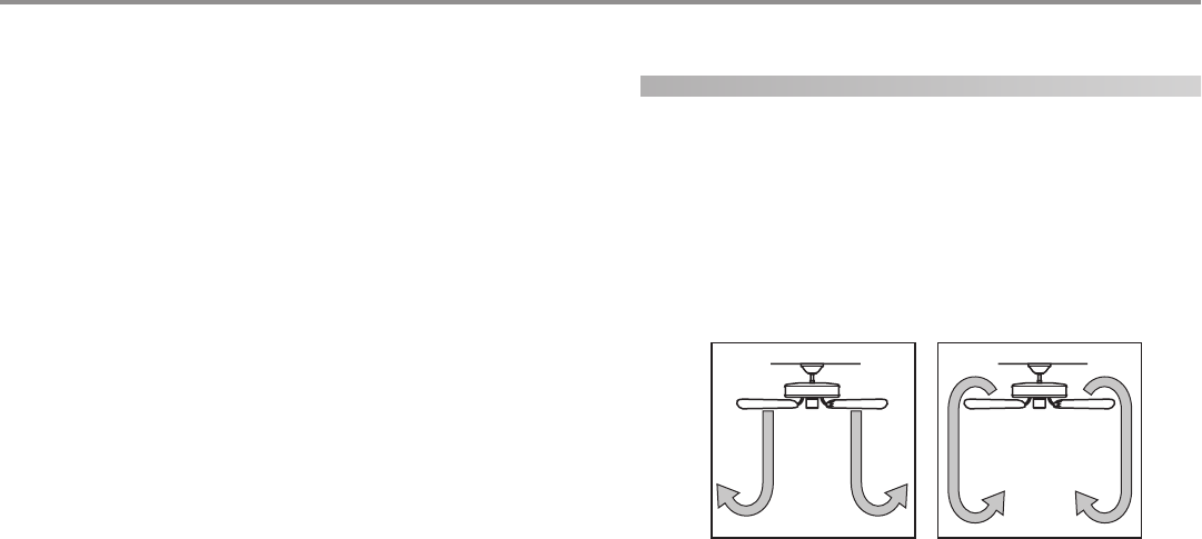
1. Turn on electrical power to the fan.
2. Ceiling fans work best by blowing air downward (counterclock-
wise blade rotation) in warm weather to cool the room with a
direct breeze. In winter, having the fan draw air upward (clock-
wise blade rotation) will distribute the warmer air trapped at
the ceiling around the room without causing a draft. Refer to
Figure 29.
FF
FF
Fii
ii
igg
gg
gurur
urur
ure 29 - Ae 29 - A
e 29 - Ae 29 - A
e 29 - Air fir f
ir fir f
ir fll
ll
loo
oo
ow pw p
w pw p
w paa
aa
att
tt
ttt
tt
tee
ee
err
rr
rnn
nn
nss
ss
s

© 2003 Hunter Fan Company 41825-01 02/05/2003
1111
1111
11
Hunter fans have the power to cut your cooling costs up to 40%.
Beat the High Cost of Cooling
The air movement created by a Hunter ceiling fan lets you set your
thermostat higher and still stay comfortable. Every degree you raise
the thermostat saves up to 7% on energy costs. So, you can cut
back on expensive air conditioning...and save up to 40%* on cool-
ing. In winter, your Hunter fan recirculates warm air and saves up
to 10%* on heating bills.
*Your savings many vary based on climate, building type and ther-
mostat setting. On average at low speed settings.
Save Energy and Money While Protecting the Environ-
ment
Congratulations! You're saving energy and money while protecting
the environment by purchasing this ENERGY STAR qualified Hunter
ceiling fan! With this purchase, you are doing your part to protect
the environment. In 2010, ENERGY STAR qualified ceiling fans are
projected to cut air pollution by more than 500 million pounds!
Your new ceiling fan has earned the ENERGY STAR label because it
meets high energy efficiency specifications set by the Environmen-
tal Protection Agency (EPA). ENERGY STAR labeled ceiling fans save
energy because they have more efficient fan motors and air deliv-
ery due to more aerodynamic blade configurations. Ceiling fan
models bearing the ENERGY STAR label move air 14 - 20% more
efficiently than typical ceiling fan models. For more information on
ENERGY STAR visit www.energystar.gov.
cleaning your ceiling fan
caring for finishes and blades
For cleaning, a soft brush or lint-free cloth should be used to pre-
vent scratching the finish. A vacuum cleaner brush nozzle can re-
move heavier dust. Surface smudges or an accumulation of dirt
and dust can easily be removed by using a mild detergent and a
slightly dampened cloth. An artistic agent may be used, but never
use abrasive cleaning agents as they will damage the finish.
replacing your light bulbs
• Contact Hunter Fan Company Customer Service at:
1-888-830-1326
• Visit the Hunter Fan Company web site at:
http://www.hunterfan.com/
• Return to the store where you purchased this light kit and use
the following guidelines in choosing a 30-Watt 4-Pin Circline
Bulb (FC8T9):
Bulb Life = 10,000 hours or greater
Color Temp = 2700 - 3000 Kelvins
CRI (Color Rendering Index) = 80 - 88
This will ensure the high quality illumination comparable to the
bulb packaged with this light kit.
troubleshooting
Problem: Nothing happens; fan does not move.
1. Turn power on, replace fuse, or reset breaker.
2. Loosen canopy, check all connections according to the
ww
ww
wirir
irir
irinin
inin
ing tg t
g tg t
g thh
hh
he fe f
e fe f
e faa
aa
ann
nn
n section.
3. Check the plug connection in the switch housing.
4. Remove the shipping bumpers.
Problem: Noisy operation.
1. Tighten the blade bracket screws until snug.
2. Tighten the blade screws until snug.
Problem: Excessive wobbling.
1. If your fan wobbles when operating, use the enclosed bal-
ancing kit and instructions to balance the fan.
2. Tighten all blade and/or blade iron screws.
3. Turn power off, support fan very carefully, and check that
the hanger ball is properly seated.
If you need parts or service assistance, please call 888-830-1326 or
visit us at our WEB site at http://www.hunterfan.com.
Hunter Fan Company
2500 Frisco Avenue
Memphis, Tennessee 38114