Hunter WRCTX Wireless Rain-Clik Rain Sensors User Manual LC Trans Manual
Hunter Industries Inc Wireless Rain-Clik Rain Sensors LC Trans Manual
UserManual.wiki
>
Hunter
>
WRCTX User Manual
>
linx tx
Contents
1.
WRC manual
2.
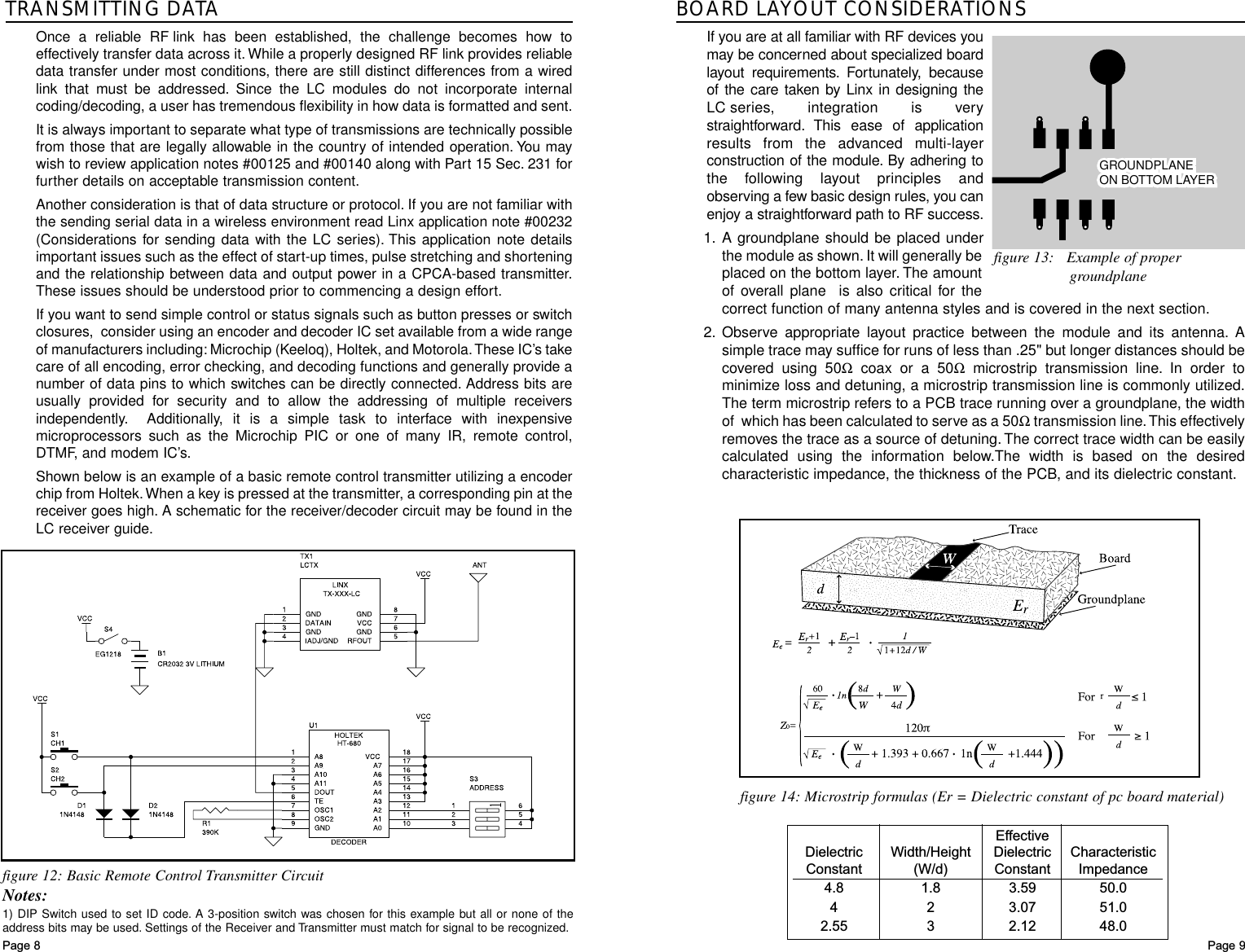
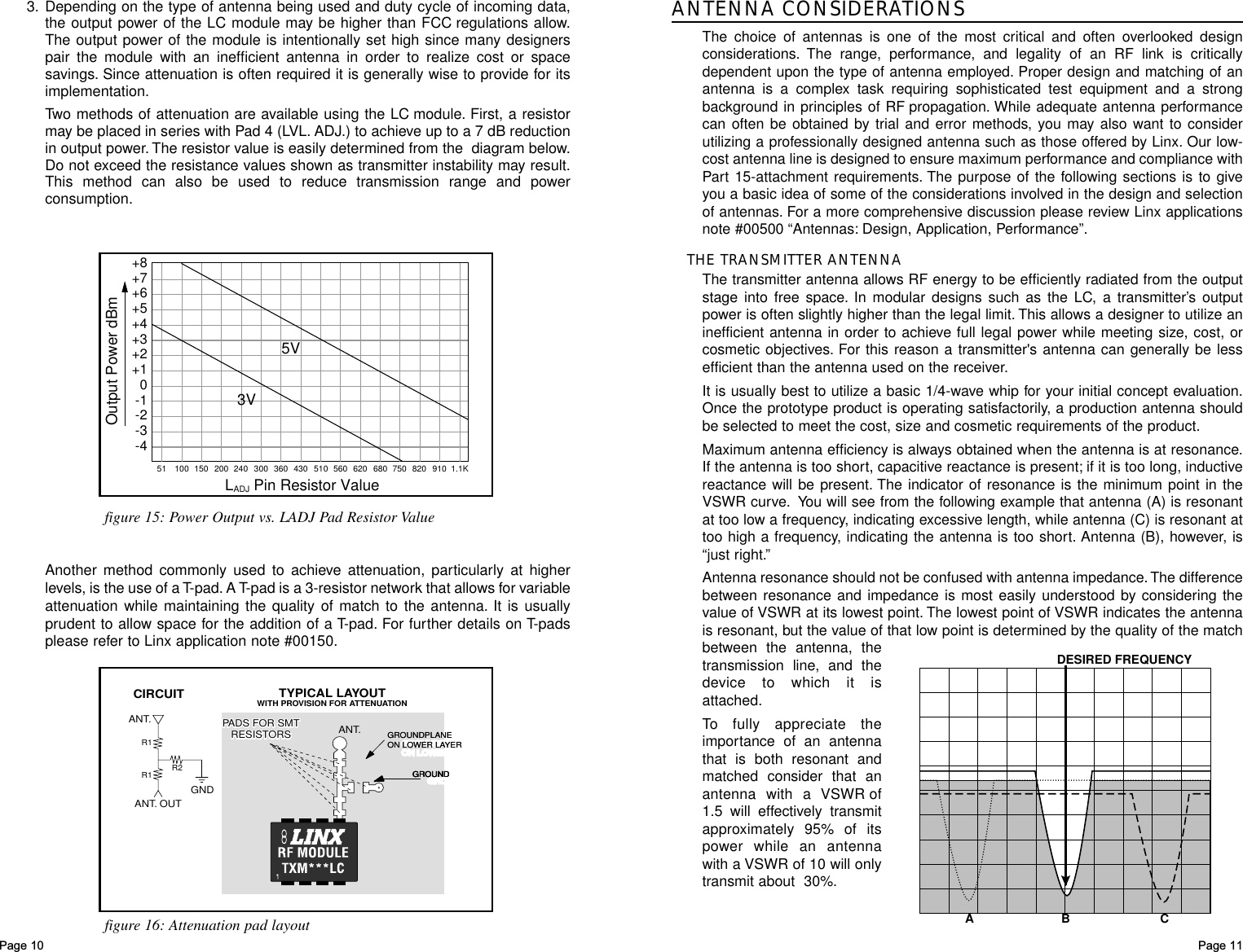
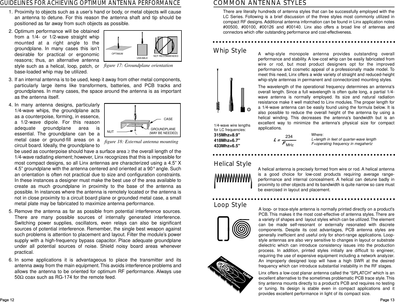
linx tx
3.
wrc brochure
linx tx
Navigation menu
Upload a User Manual
Namespaces
Wiki Guide
HTML
PDF
Info
Views
User Manual
Discussion / Help
Navigation