Hunter WSSTX Wireless Rain-Clik Transmitter User Manual 23 461 RevC WRC Inst Sheet
Hunter Industries Inc Wireless Rain-Clik Transmitter 23 461 RevC WRC Inst Sheet
Hunter >
Users Manual
Wireless Rain-Clik™ Rain Sensors
Installation Instructions
INTRODUCTION
The Wireless Rain-Clik™ acts as a switch to break the circuit to the solenoid
valves of the irrigation system when it has rained. This allows the timer to
advance as scheduled, but keeps the valves from opening the water ow. Once
the Wireless Rain-Clik has dried sufciently, the switch closes again to allow for
normal operation.
The Wireless Rain/Freeze-Clik® includes a freeze sensor that is designed to
keep the system from operating at, or below 3°C (37°F). At temperatures above
3°C, it will close the circuit for normal sprinker operation.
CONTENTS
Included with the Wireless
Rain-Clik are the following items:
1. Sensor body with Transmitter
2. Telescoping extension arm
3. Wall mount / Conduit adapter
4. Gutter clip
5. Mounting Hardware
6. Receiver
7. Cover for Receiver
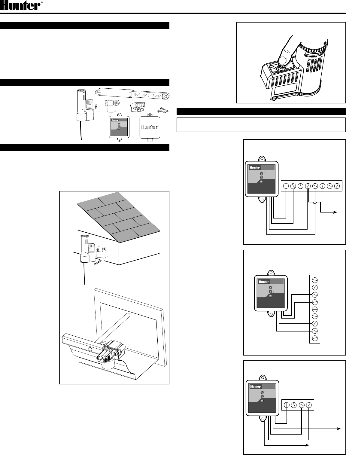
MOUNTING
Standard Mount:
Using the screws provided, mount the Wireless Rain-Clik transmitter on any
surface where it will be exposed to unobstructed rainfall, but not in the path of
sprinkler spray. The switch-housing portion must be upright (as pictured), but
the swivel-bracket can be moved for mounting on any angled surface.
Gutter Mount:
Clip the enclosed gutter
mounting bracket over
the inside lip of the gutter.
Attach the Wireless
Rain-Clik to the gutter
mounting bracket with the
screws provided.
Helpful Hints for
Mounting:
A. Choose a location
such as on the side of
a building or post, the
closer the Wireless
Rain-Clik is to the
controller, the better
reception will be. DO
NOT EXCEED 300
feet.
B. Correct placement
of the Wireless
Rain/Freeze-Clik is
important for accurate
temperature sensing.
The best location for
mounting would be out
of direct sunlight.
C. As described in the
“Operation” section
of this manual, “reset
rate” refers to the
amount of time it takes
the Wireless Rain-Clik
to dry out sufciently
for the sprinkler
system to be allowed
to come back on.
Mounting the Wireless Rain-Clik on a very sunny, southern end of a building
may cause the Wireless Rain-Clik to dry out sooner than desired. Similarly,
mounting on the northern end of a building with constant shade may keep
the Wireless Rain-Clik from drying soon enough.
Transmitters/Sensor
• Nothing to set up with this unit after installation
• The unit can be tested stand-alone as follows: press and hold the post on
the quick response section. Within 3 seconds of pressing and holding this
post down, the LED protruding from the potting should blink once. Release
the post, within 3
seconds the LED
should blink once
again. (Figure 1)
Receiver
• Using the hardware
included, mount the
receiver to the wall
(use included wall
anchors if needed).
Make sure to put the
rubber cover/gasket
under the unit when
attaching it in an
outdoor location.
WIRING TO YOUR IRRIGATION SYSTEM
WARNING! This unit is designed to be installed in conjunction with 24VAC
circuits only. Do not use with 110 or 220VAC circuits.
Receiver Installation, SRC Controller: (See Figure 2)
1. Attach the two yellow
wires to the AC terminals
of the SRC (polarity does
not matter).
2. Attach the blue wire to the
RS terminal.
3. Attach the white wire to
the “C” terminal.
4. Attach the valve common
wire to the RS terminal.
Receiver Installation,
Pro-C and ICC Controllers:
(See Figure 3)
1. Attach the two yellow
wires to the AC terminals
of the controller (polarity
does not matter).
2. Attach the blue wire to
one SEN terminal and
the white wire to the
other SEN terminal of the
controller.
Receiver Installation, Other
Controllers:
A. Normally Closed
Sensor Applications
(See Figure 4)
1. Attach the two yellow
wires to the AC terminals
of the controllers (polarity
does not matter).
2. To attach the receiver
to this type of controller,
attach the blue wire and
the white wire to the
sensor terminals of the
controller, or in-line with
the valve common.
B. Normally Open Sensor
Applications
1. A few controllers on the
market require a normally
open rain sensor. To
attach the receiver to
this type of controller,
attach the blue wire and
the orange wire to the
controller’s sensor input.
Gutter
Mount
Standard
Mount
Figure 1
Manually depress the spindle at
the top of the Wireless Rain-Clik
Wireless
Rain Sensor
Hunter SRC
Figure 2
R RS C 1ACAC 2 3
W
B
Y
YCommon Wire
to all Valves
Red light indicates
sensor is bypassed
GREEN = Sensor is dry
RED = Sensor is wet
SENSOR BYPASS
SENSOR STATUS
WIRELESS
RAIN SENSOR
RAIN SENSOR
Press to bypass, press
again to re-enable
Figure 3
Wireless
Rain Sensor Hunter ICC/Pro-C
SEN
SEN
C
TEST
P MV
AC
AC
G
REM
Red light indicates
sensor is bypassed
GREEN = Sensor is dry
RED = Sensor is wet
SENSOR BYPASS
SENSOR STATUS
WIRELESS
RAIN SENSOR
RAIN SENSOR
Press to bypass, press
again to re-enable
B
W
Y
Y
Other
Controllers
Figure 4
P MVC
Wireless
Rain Sensor
AC AC
W
B
Y
Y
O
Common Wire
to all Valves
Used for normally
open sensor
applications
Red light indicates
sensor is bypassed
GREEN = Sensor is dry
RED = Sensor is wet
SENSOR BYPASS
SENSOR STATUS
WIRELESS
RAIN SENSOR
RAIN SENSOR
Press to bypass, press
again to re-enable
➀➂➃➄
➁
Red light indicates
sensor is bypassed
GREEN = Sensor is dry
RED = Sensor is wet
SENSOR BYPASS
SENSOR STATUS
WIRELESS
RAIN SENSOR
RAIN SENSOR
Press to bypass, press
again to re-enable
➆➅
Wireless Rain-Clik™ Rain Sensors
Installation Instructions
Hunter Industries Incorporated • The Irrigation Innovators
© 2004 Hunter Industries Incorporated
www.HunterIndustries.com 23-461 2/04
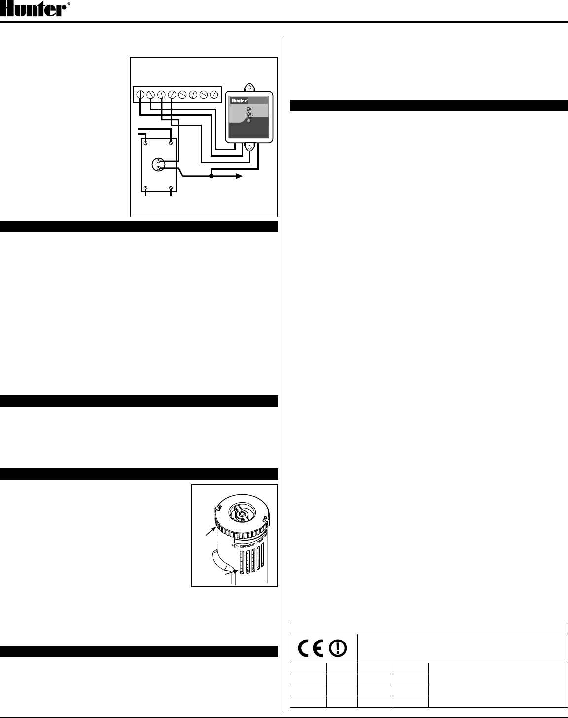
Receiver Installation, Other Controllers (continued):
C. 24 Volt Solenoid Valves with Booster Pump (See Figure 5)
Locate the common wire to
the solenoid valves and the
common wire leading to the coil
of the relay that starts the pump.
If these two wires are connected
to the “common” terminal on the
controller, disconnect both of
them.
Twist together these two wires
along with one wire from the
Rain-Clik™, and secure with a
wire nut. Attach the other wire
of the Wireless Rain-Clik™
receiver to the “common”
terminal on the controller. Note:
The pump circuit output must be
24 Volts in this situation. Do not
proceed if 110V.
SETTING THE TRANSMITTER ADDRESS AT THE RECEIVER
Units purchased as a kit will already have their address learned.
No addressing is necessary, however if the receiver or transmitter is
replaced, you need to reset the address.
Each transmitter produced has a unique address hard-coded into it. A receiver
must learn this address to work with that transmitter. This step will only be
necessary if transmitters and receivers are purchased separately.
1. Prior to applying power (yellow wires) to the receiver, press and hold the
receivers pushbutton.
2. While the pushbutton is being held apply power to the receiver – the
receiver’s “sensor status” LED should light up yellow indicating the receiver
is ready to learn an address.
3. Push and hold the quick response post on the transmitter/sensor.
4. Within 4 seconds, the receiver’s “sensor status” LED should turn red.
5. Release the transmitter/sensor’s quick response post and within 4 seconds
the LED on the receiver should turn green. The address is now learned and
will be retained even in the event of a power outage.
OPERATION
The receiver has two LEDs, which indicate the state of the system. The STATUS
LED will be RED when the sensor is wet (watering disabled), and GREEN when
the sensor is dry (watering enabled). There is also a RED BYPASS LED on the
receiver. If this LED is lit, the rain sensor is bypassed and watering will always
be allowed. Even though the sensor is bypassed, the STATUS LED will continue
to alert you of the state of the sensor (Wet or Dry).
ADJUSTMENTS AND OPERATION
The Wireless Rain-Clik can keep the irrigation
system from starting or continuing after rainfall.
The time that it takes the Wireless Rain-Clik to
reset for normal sprinkler operation after the rain
has stopped is determined by weather conditions
(wind, sunlight, humidity, etc.). These conditions will
determine how fast the hydroscopic discs dry out,
and since the turf is also experiencing the same
conditions, their respective drying rates will roughly
parallel each other. So when the turf needs more
water, the Rain-Clik is already reset to allow the
sprinkler system to go at the next scheduled cycle.
There is an adjustment capability on the Wireless Rain-Clik that will slow down
the reset rate. By closing the “vent” (see Figure 6) to completely or partially
cover the ventilation slots, the hydroscopic discs will dry more slowly. This
adjustment can compensate for an “overly sunny” installation location, or
peculiar soil conditions. Experience will best determine the ideal vent setting.
BYPASSING THE SENSOR
The sensor may be bypassed by using the built in bypass feature in the SRC,
Pro-C or ICC. On other controllers the sensor may be bypassed by pressing
the “BYPASS” button on the receiver. The RED BYPASS LED on the receiver
will be lit when the sensor is bypassed. Pressing the “BYPASS” button again will
cause the RED BYPASS LED to go back out thus re-enabling the sensor.
Battery Life: The Wireless Rain-Clik transmitter is designed to work daily
for up to ten years with the original battery. The sealed unit is available as a
replacement part. Should you need to change the transmitter the receiver will
have to learn the new transmitter address.
There is no required maintenance for the unit. The Wireless Rain-Clik does not
have to be removed or covered for “winterizing” purposes.
TROUBLESHOOTING
Follow these simple checks rst before assuming the unit is bad and replacing it.
System will not come on at all:
A. First, check to see that the Wireless Rain-Clik discs are dry and the switch
“clicks” on and off freely by pressing the top of the spindle.
B. Next, look for breaks in the wire leading to the Wireless Rain-Clik receiver
and check all wire junctions.
System will not shut off even after heavy rainfall:
A. Check wiring for correctness (see “Operation Check to Verify Correct
Wiring”).
B. Is the rainfall actually hitting the Wireless Rain-Clik? Check for obstructions
to rainfall such as overhangs, trees or walls.
Manufactured under U.S. Patent 6,570,109 B2
All Rain-Clik models are listed by Underwriters Laboratories, Inc. (UL). Samples of these devices have
been evaluated by UL and meet the applicable UL standards for safety.
FCC Compliance Notice
This notice applies only to models WRC-TR and WRFC-TR
This device complies with FCC rules Part 15. Operation is subject to the
following two conditions:
1) This device may not cause harmful interference and
2) This device must accept any interference that may be received, including
interference that may cause undesired operation
Transmitter FCC ID: M3UWSSTX
This equipment has been tested and found to comply with the limits for a
class B digital device, pursuant to part 15 of the FCC Rules. These limits
are designed to provide reasonable protection against harmful interference
in a residential installation. This equipment generated, uses and can radiate
radio frequency energy and if not installed and used in accordance with the
instructions, may cause harmful interference to radio communications. However,
there is no guarantee that interference will not occur in a particular installation.
If this equipment does cause harmful interference to radio or television
reception, which can be determined by turning the equipment off and on, the
user is encouraged to try to correct the interference by one or more of the
following measures:
• Reorient or relocate the receiving antenna
• Increase the separation between the equipment and receiver
• Connect the equipment into an outlet on a circuit different from that to which
the receiver is connected
• Consult the dealer or an experienced radio/TV technician for help
Industry of Canada Notice
This notice applies only to models WRC-TR and WRFC-TR
IC: 277A-14198
WRC-R: This Class B digital aparatus complies with Canadian ICES-003.
The term “IC:” before the certication/registration number only signies that the
Industry of Canada technical specications were met.
Operation is subject to the following two conditions: (1) this device may not
cause interference, and (2) this device must accept any interference, including
interference that may cause undesired operation of the device.
CE Notice: this notice applies only to models WRC-INT.
Important Notice:
Low power RF product operating in 433.92MHz band for
indoor or outdoor home and commercial use.
AUS B DK FIN Member states in the EU with
restrictive use for this product are
crossed out.
F D GR IRE
I LUX NL P
E S UK
Figure 5
Normally-
Open Relay
1 2 3 4
Controller
C
Solenoid
Valves
Common
Wire to All
Valves
Pump
or
MV
Line-In
Line-Out (to Pump)
Wireless
Rain Sensor
AC AC
Y
Y
W
B
Red light indicates
sensor is bypassed
GREEN = Sensor is dry
RED = Sensor is wet
SENSOR BYPASS
SENSOR STATUS
WIRELESS
RAIN SENSOR
RAIN SENSOR
Press to bypass, press
again to re-enable
Figure 6
Vent Ring
Vents