Husqvarna 128CD User Manual TRIMMER Manuals And Guides L0912310
HUSQVARNA Line Trimmers/Weedwackers, Gas Manual L0912310 HUSQVARNA Line Trimmers/Weedwackers, Gas Owner's Manual, HUSQVARNA Line Trimmers/Weedwackers, Gas installation guides
User Manual: Husqvarna 128CD 128CD HUSQVARNA TRIMMER - Manuals and Guides View the owners manual for your HUSQVARNA TRIMMER #128CD. Home:Lawn & Garden Parts:Husqvarna Parts:Husqvarna TRIMMER Manual
Open the PDF directly: View PDF ![]() .
.
Page Count: 52

Operator's manual
Manuel d'utilisation
Manual de instrucciones
128CD 128LD
Please read these instructions and make sure you understand them before using the machine.
Life attentivement et bien assimiler le manuel d'utilisation avant d'utiliser la machine.
Lea detenidamente el manual de instrucciones y aseg_rese de entender su contenido antes de utilizar la m_quina.
EN (2-25)
FR (26-49)
ES (50-75)
CONTENTS
Contents
CONTENTS
Contents ........................ 2
Note the following before starting .... 2
KEY TO SYMBOLS
Symbols ......................... 3
SAFETY INSTRUCTIONS
Personal protective equipment ...... 4
Machine's safety equipment ........ 4
Cutting equipment ................. 5
Checking, maintaining and servicing
the machine's safety equipment ..... 5
General safety precautions ......... 8
Starting ......................... 9
Fuel safety ....................... 9
Transporting and storage ........... 9
General working instructions ........ 9
Basic safety rules ................. 9
Basic working techniques .......... 10
KNOW YOUR TRIMMER
Know your trimmer ................ 12
ASSEMBLY
Fitting the loop handle ............. 13
Assembling and dismantling the
two-piece shaft ................... 13
Fitting the trimmer guard and
trimmer head ..................... 13
FUEL HANDLING
Fuel ............................ 15
Fueling .......................... 15
STARTING AND STOPPING
Check before starting .............. 16
Starting and stopping .............. 16
MAINTENANCE
Carburetor ....................... 18
Muffler .......................... 18
Spark plug ....................... 19
Two-piece shart .................. 19
Air filter .......................... 19
Bevel gear ....................... 19
Maintenance schedule ............. 20
Trimmer head line loading instructions .. 21
TECHNICAL DATA
Technical data .................... 22
WARRANTY STATEMENT ......... 23
EMISSION CONTROL
WARRANTY STATEMENT ......... 24
Note the following before
starting:
Husqvarna AB has a policy of continuous
product development and therefore
reserves the right to modify the design and
appearance of products without prior
notice. Long-term exposure to noise can
result in permanent hearing impairment.
Always use approved hearing protection.
Maintenance, replacement, or repair of the
emission control devices and system may
be performed by any nonroad engine re-
pair establishment or individual.
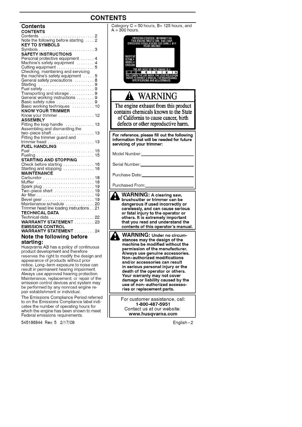
The Emissions Compliance Period referred
to on the Emissions Compliance label indi-
cates the number of operating hours for
which the engine has been shown to meet
Federal emissions requirements.
Category C = 50 hours, B= 125 hours, and
A = 300 hours.
WARNING
Theengine exhaust from thisproduct
contains chemicalsknownto the State
of California to causecancer,birth
defects or other reproductiveharm.
For reference, please fill out the following
information that will be needed for future
servicing of your trimmer:
Model Number:
Serial Number:
Purchase Date:
Purchased From:
WARNING: Aclearingsaw,
bruahcutter or trimmer can be
dangerous if used incorrectly or
carelessly, and can cause serious
or fatal injury to the operator or
others. It is extremely important
that you read and understand the
contents of this operator's manual.
WARNING: Under no circum-
stances may the design of the
machine be modified without the
permission of the manufacturer.
Always use genuine accessories.
Non-authorized modifications
and/or accessories can result
in serious personal injury or the
death of the operator or others.
Your warranty may not cover
damage or liability caused by the
use of non-authorized accesso-
ries or replacement parts.
For customer assistance, call:
1-800-487-5951
Contact us at our website:
www, husqvarna,oom
English-2
545186844 Rev. 5 2/17/09
KEY TO SYMBOLS
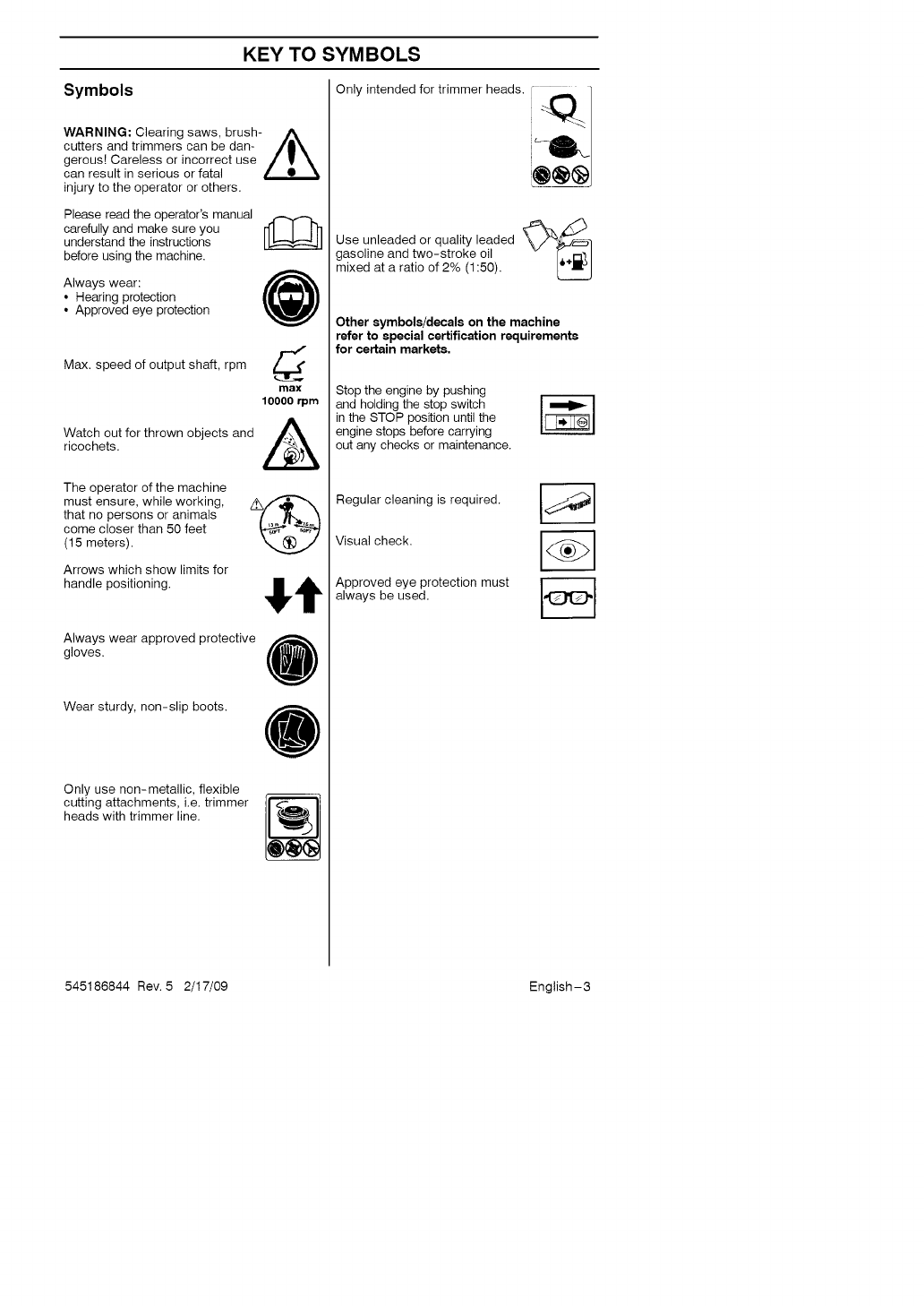
Symbols
WARNING: Clearing saws, brush- A
cutters and trimmers can be dan- /|_
gerous! Careless or incorrect use /_ '_
can result in serious or fatal
injury to the operator or others.
Please read the operator's manual
carefully and make sure you
understand the instructions
before using the machine.
Always wear: @
• Hearing protection
• Approved eye protection
Max. speed of output shaft, rpm d
max
10000 rprn
Watchricochets.OUtfor thrown objects and ,i_
The operator of the machine
must ensure, while working,
that no persons or animals
come closer than 50 feet
(15 meters).
Arrows which show limits for
handle positioning.
Always wear approved protective
gloves. U
Wear sturdy, non-slip boots.
Only use non-metallic, flexible
cutting attachments, i.e. trimmer
heads with trimmer line.
Only intended for trimmer heads, i_
Use unleaded or quality leaded \_
gasoline and two-stroke oil
mixed at a ratio of 2% (1:50).
Other symbols/decals on the machine
refer to special certification requirements
for certain markets.
Stop the engine by pushing
and holding the stop switch
in the STOP position until the
engine stops before carrying
out any checks or maintenance.
Regular cleaning is required.
Visual check.
Approved eye protection must
always be used.
545186844 Rev. 5 2/17/09 English-3
SAFETY INSTRUCTIONS
Personal protective equipment
IMPORTANT! Whenever you use a clear-
ing saw, brushcutter or trimmer you must
wear personal protective equipment that is
approved by the authorities. Personal
protective equipment does not eliminate
the risk of accidents, but it can reduce the
effects of an injury in the event of an acci-
dent. Ask your dealer for help when
choosing protective equipment.
WARNING: Listen out for warn-
ing signals or shouts when you are
wearing hearing protection. Always
remove your hearing protection as
soon as the engine stops.
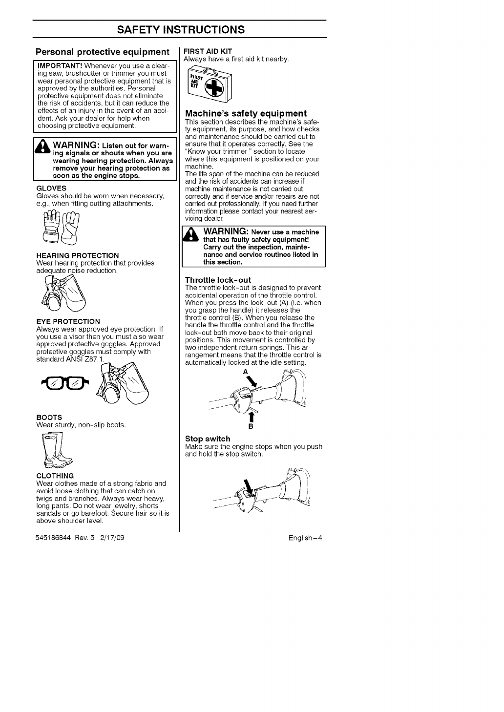
GLOVES
Gloves should be worn when necessary,
e.g., when fitting cutting attachments.
HEARING PROTECTION
Wear hearing protection that provides
adequate noise reduction.
EYE PROTECTION
Always wear approved eye protection. If
you use a visor then you must also wear
approved protective goggles. Approved
protective goggles must comply with
standard ANSI Z87.1.
BOOTS
Wear sturdy, non-slip boots.
CLOTHING
Wear clothes made of a strong fabric and
avoid loose clothing that can catch on
twigs and branches. Always wear heavy,
long pants. Do not wear jewelry, shorts
sandals or go barefoot. Secure hair so it is
above shoulder level.
FIRST AID KIT
Always have a first aid kit nearby.
Machine's safety equipment
This section describes the machine's safe-
ty equipment, its purpose, and how checks
and maintenance should be carried out to
ensure that it operates correctly. See the
"Know your trimmer" section to locate
where this equipment is positioned on your
machine.
The life span of the machine can be reduced
and the risk of accidents can increase if
machine maintenance is not carried out
correctly and if service and/or repairs are not
carried out professionally. If you need further
information please contact your nearest ser-
vicing dealer.
WARNING: Never use a machine
that has faulty safety equipment[
Carry out the inspection, mainte-
nance and service routines listed in
this section.
Throttle lock-out
The throttle lock-out is designed to prevent
accidental operation of the throttle control.
When you press the lock-out (A) (i.e. when
you grasp the handle) it releases the
throttle control (B). When you release the
handle the throttle control and the throttle
lock-out both move back to their original
positions. This movement is controlled by
two independent return springs. This ar-
rangement means that the throttle control is
automatically locked at the idle setting.
A
Stop switch
Make sure the engine stops when you push
and hold the stop switch.
545186844 Rev. 5 2/17/09 English-4
SAFETY INSTRUCTIONS
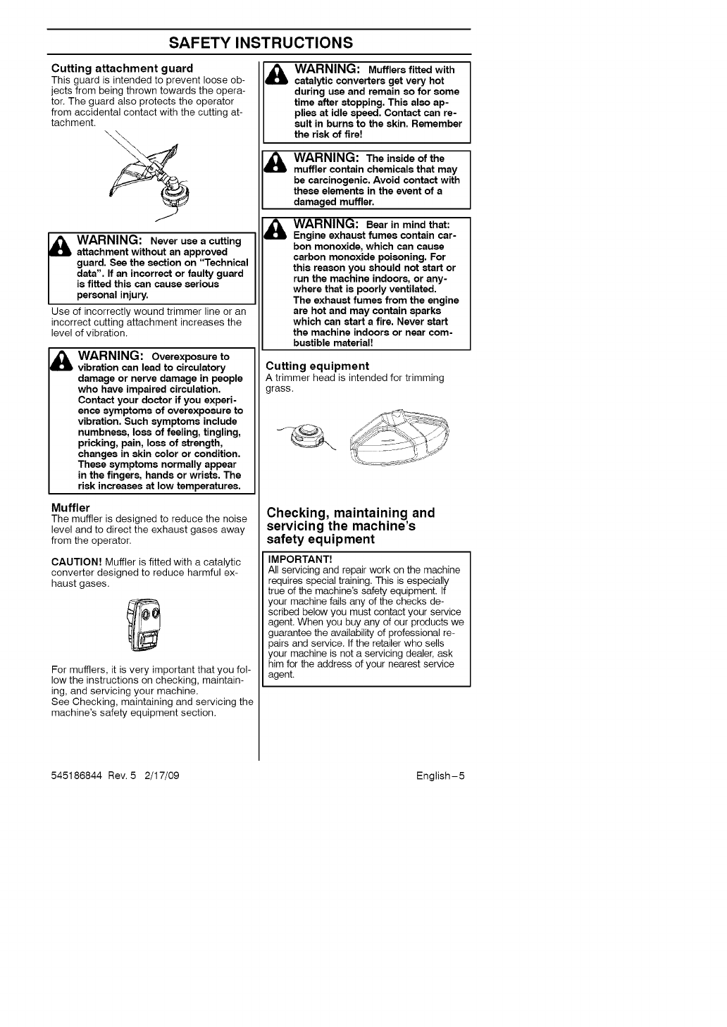
Cutting attachment guard
This guard is intended to prevent loose ob-
jects from being thrown towards the opera-
tor. The guard also protects the operator
from accidental contact with the cutting at-
tachment.
_ARNING: Never use a cutting
attachment without an approved
guard. See the section on "Technical
data". If an incorrect or faulty guard
is fitted this can cause serious
personal injury.
Use of incorrectly wound trimmer line or an
incorrect cutting attachment increases the
level of vibration.
WARNING: Overexposure to
vibration can lead to circulatory
damage or nerve damage in people
who have impaired circulation.
Contact your doctor if you experi-
enca symptoms of overexposure to
vibration. Such symptoms include
numbness, loss of feeling, tingling,
pricking, pain, loss of strength,
changes in skin color or condition.
These symptoms normally appear
in the fingers, hands or wrists. The
risk increases at low temperatures.
Muffler
The muffler is designed to reduce the noise
level and to direct the exhaust gases away
from the operator.
CAUTION! Muffler is fitted with a catalytic
converter designed to reduce harmful ex-
haust gases.
For mufflers, it is very important that you fol-
low the instructions on checking, maintain-
ing, and servicing your machine.
See Checking, maintaining and servicing the
machine's safety equipment section.
&WARNING: Mufflers fitted with
catalytic converters get very hot
during use and remain so for some
time after stopping. This also ap-
plies at idle speed. Contact can re-
sult in burns to the skin. Remember
the risk of fire!
&
M
WARNING: The inside of the
muffler contain chemicals that may
be carcinogenic. Avoid contact with
these elements in the event of a
damaged muffler.
WARNING: Bear in mind that:
Engine exhaust fumes contain car-
bon monoxide, which can cause
carbon monoxide poisoning. For
this reason you should not start or
run the machine indoors, or any-
where that is poorly ventilated.
The exhaust fumes from the engine
are hot and may contain sparks
which can start a fire. Never start
the machine indoors or near com-
bustible material!
Cutting equipment
A trimmer head is intended for trimming
grass.
Checking, maintaining and
servicing the machine's
safety equipment
IMPORTANT!
All servicing and repair work on the machine
requires special training. This is especially
true of the machine's safety equipment. If
your machine fails any of the checks de-
scribed below you must contact your service
agent. When you buy any of our products we
guarantee the availability of professional re-
pairs and service. If the retailer who sells
your machine is not a servicing dealer, ask
him for the address of your nearest service
agent.
545186844 Rev. 5 2/17/09 English-5
SAFETY INSTRUCTIONS
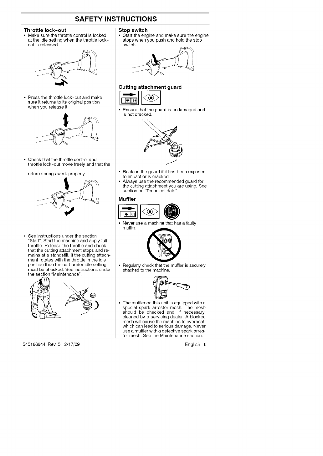
Throttle lock-out
• Make sure the throttle control is locked
at the idle setting when the throttle lock-
out is released.
• Press the throttle lock-out and make
sure it returns to its original position
when you release it.
• Check that the throttle control and
throttle lock-out move freely and that the
return springs work properly.
• See instructions under the section
"Start". Start the machine and apply full
throttle. Release the throttle and check
that the cutting attachment stops and re-
mains at a standstill. If the cutting attach-
ment rotates with the throttle in the idle
position then the carburetor idle setting
must be checked. See instructions under
the section "Maintenance".
Stop switch
• Start the engine and make sure the engine
stops when you push and hold the stop
switch.
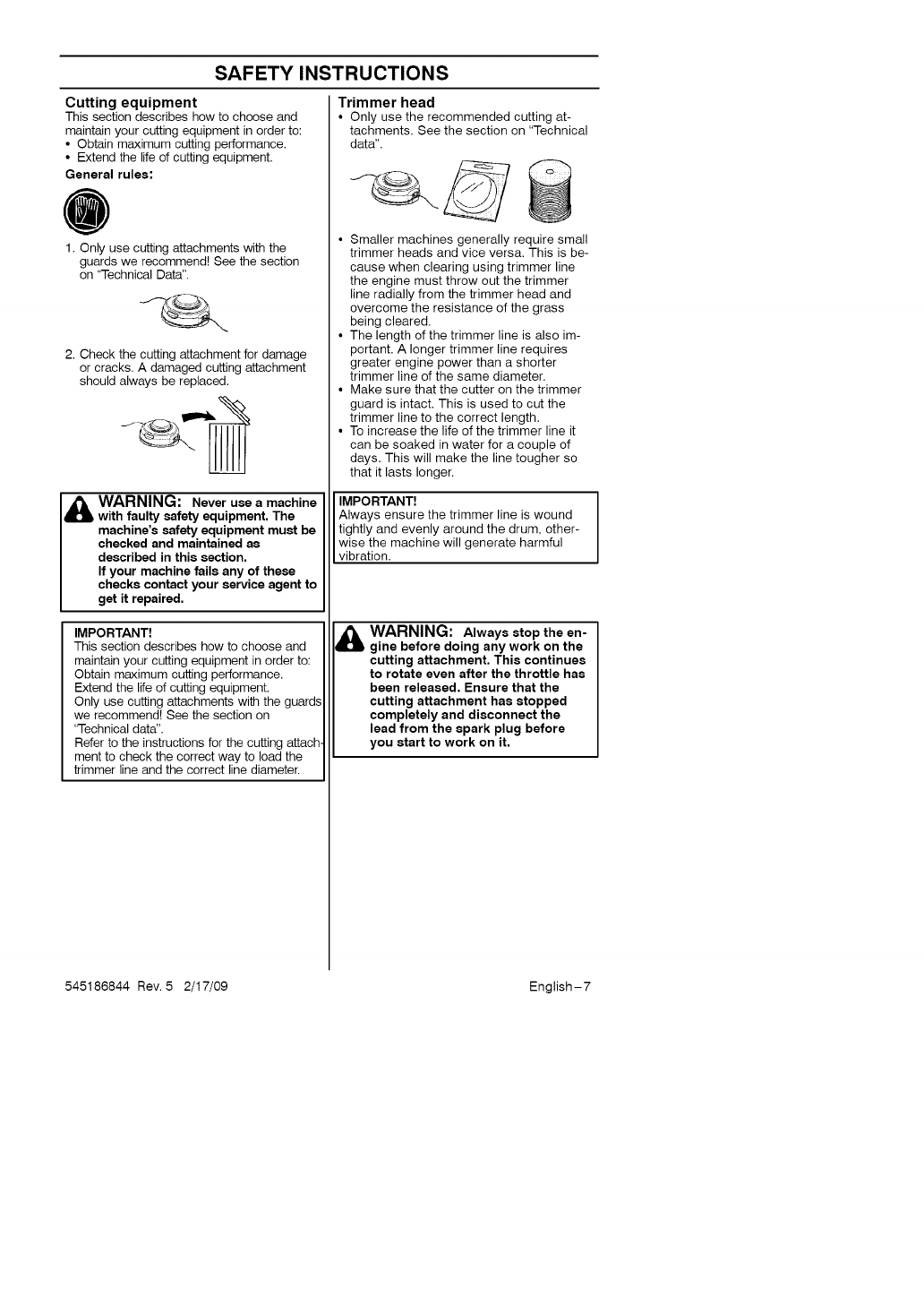
Cutting attachment guard
• Ensure that the guard is undamaged and
is not cracked.
• Replace the guard if it has been exposed
to impact or is cracked.
• Always use the recommended guard for
the cutting attachment you are using. See
section on "Technical data".
Muffler
• Never use a machine that has a faulty
muffler. @
• Regularly check that the muffler is securely
attached to the machine.
• The muffler on this unit is equipped with a
special spark arrestor mesh. The mesh
should be checked and, if necessary.
cleaned by a servicing dealer. A blocked
mesh will cause the machine to overheat,
which can lead to serious damage. Never
use a muffler with a defective spark arres-
tor mesh. See the Maintenance section.
545186844 Rev. 5 2/17/09 English-6
SAFETY INSTRUCTIONS
Cutting equipment
This section describes how to choose and
maintain your cutting equipment in order to:
• Obtain maximum cutting performance.
• Extend the life dcutting equipment.
General rules:
1. Only use cutting attachments with the
guards we recommend! See the section
on "Technical Data".
2. Check the cutting attachment for damage
or cracks. A damaged cutting attachment
should always be replaced.
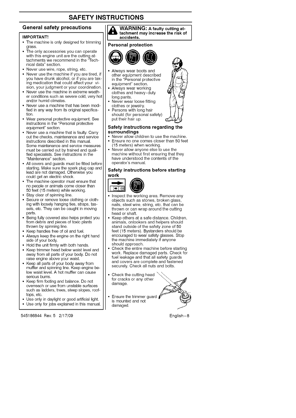
Trimmer head
• Only use the recommended cutting at-
tachments. See the section on "Technical
data".
• Smaller machines generally require small
trimmer heads and vice versa. This is be-
cause when clearing using trimmer line
the engine must throw out the trimmer
line radially from the trimmer head and
overcome the resistance of the grass
being cleared.
• The length of the trimmer line is also im-
portant. A longer trimmer line requires
greater engine power than a shorter
trimmer line of the same diameter.
• Make sure that the cutter on the trimmer
guard is intact. This is used to cut the
trimmer line to the correct length.
• To increase the life of the trimmer line it
can be soaked in water for a couple of
days. This will make the line tougher so
that it lasts longer.
WARNING: Never use a machine
with faulty safety equipment. The
machine's safety equipment must be
checked and maintained as
described in this section.
If your machine fails any of these
checks contact your service agent to
get t repa red,
IMPORTANT!
This section describes how to choose and
IMPORTANT!
Always ensure the trimmer line is wound
tightly and evenly around the drum, other-
wise the machine will generate harmful
v brat on.
WARNING: Always stop the en-
gine before doing any work on the
maintain your cutting equipment in order to:
Obtain maximum cutting performance.
Extend the life of cutting equipment.
Only use cutting attachments with the guards
we recommend! See the section on
"Technical data".
Refer to the instructions for the cutting attach
ment to check the correct way to load the
trimmer line and the correct line diameter.
cutting attachment. This continues
to rotate even after the throttle has
been released, Ensure that the
cutting attachment has stopped
completely and disconnect the
lead from the spark plug before
you start to work on it,
545186844 Rev. 5 2/17/09 English-7
SAFETY INSTRUCTIONS
General safety precautions
IMPORTANT!
• The machine is only designed for trimming
grass.
• The only accessories you can operate
with this engine unit are the cutting at-
tachments we recommend in the "Tech-
nical data" section.
• Never use wire, rope, string, etc.
• Never use the machine if you are tired, if
you have drunk alcohol, or if you are tak-
ing medication that could affect your vi-
sion, your judgment or your coordination.
• Never use the machine in extreme weath-
er conditions such as severe cold, very hot
and/or humid climates.
• Never use a machine that has been modi-
fied in any way from its original specifica-
tion.
• Wear personal protective equipment. See
instructions in the "Personal protective
equipment" section.
• Never use a machine that is faulty. Carry
out the checks, maintenance and service
instructions described in this manual.
Some maintenance and service measures
must be carried out by trained and quali-
fied specialists. See instructions in the
"Maintenance" section.
• All covers and guards must be fitted before
starting. Make sure the spark plug cap and
lead are not damaged. Otherwise you
could get an electric shock.
• The machine operator must ensure that
no people or animals come closer than
50 feet (15 meters) while working.
• Stay clear of spinning line.
• Secure or remove loose clothing or cloth-
ing with loosely hanging ties, straps, tas-
sels, etc. They can be caught in moving
parts.
• Being fully covered also helps protect you
from debris and pieces of toxic plants
thrown by spinning line.
• Keep handles free of oil and fuel.
• Always keep the engine on the right hand
side of your body.
• Hold the unit firmly with both hands.
• Keep trimmer head below waist level and
away from all parts of your body. Do not
raise engine above your waist.
• Keep all parts of your body away from
muffler and spinning line. Keep engine be-
low waist level. A hot muffler can cause
serious burns.
• Keep firm footing and balance. Do not
overreach or use from unstable surfaces
such as ladders, trees, steep slopes, roof-
tops, etc.
• Use only in daylight or good artificial light.
• Use only for jobs explained in this manual.
WARNING: A faulty cutting at- ]
tachment may increase the risk of
accidents.
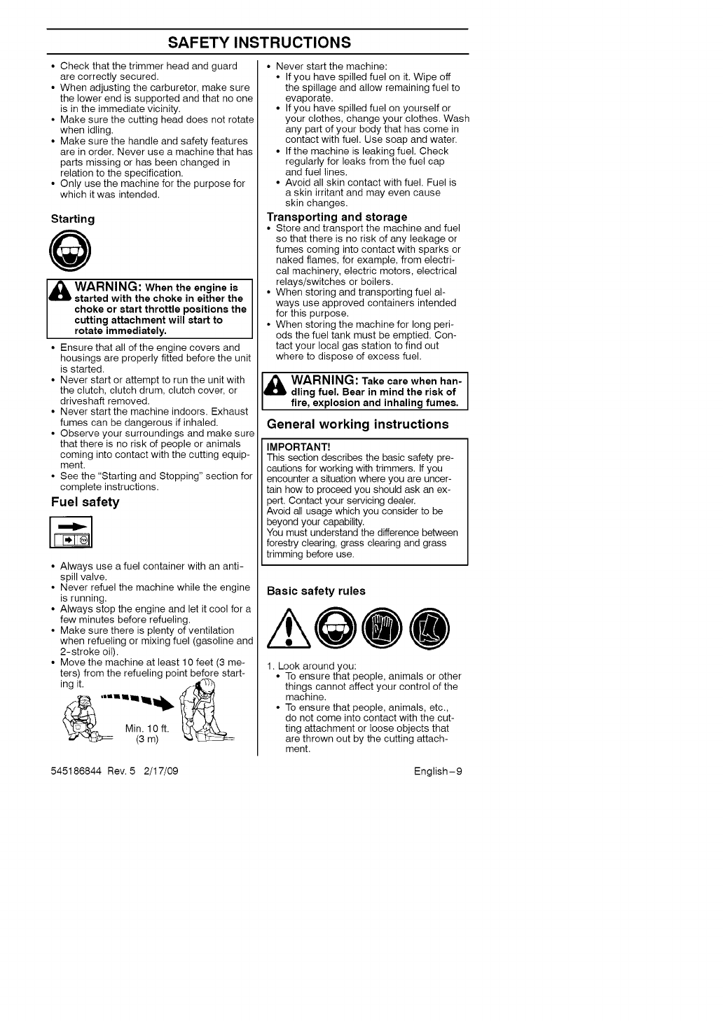
Personal protection
@@@
• Always wear boots and
other equipment described
in the "Personal protective
equipment" section.
• Always wear working
clothes and heavy-duty
long pants.
• Never wear loose fitting
clothes or jewelry.
• Persons with long hair
should (for personal safety)
put their hair up.
Safety instructions regarding the
surroundings
• Never allow children to use the machine.
• Ensure no one comes closer than 50 feet
(15 meters) when working.
• Never allow anyone else to use the
machine without first ensuring that they
have understood the contents of the
operator's manual.
Safety instructions before starting
work
• Inspect the working area. Remove any
objects such as stones, broken glass,
nails, steel wire, string, etc. that can be
thrown or can wrap around the cutting
head or shaft.
• Keep others at a safe distance. Children,
animals, onlookers and helpers should
stand outside of the safety zone of 50
feet (15 meters). Bystanders should be
encouraged to wear safety glasses. Stop
the machine immediately if anyone
should approach.
• Check the entire machine before starting
work. Replace damaged parts. Check for
fuel leakage and that all safety guards
and covers are complete and fastened
securely. Check all nuts and bolts.
• Check the cutting head _'_\
for cracks or any other _\ _._
damage.
Ensure the trimmer guard iV _j
is mounted and not _l_J
damaged.
545186844 Rev. 5 2/17/09 English-8
SAFETY INSTRUCTIONS
• Check that the trimmer head and guard
are correctly secured.
• When adjusting the carburetor, make sure
the lower end is supported and that no one
is in the immediate vicinity.
• Make sure the cutting head does not rotate
when idling.
• Make sure the handle and safety features
are in order. Never use a machine that has
parts missing or has been changed in
relation to the specification.
• Only use the machine for the purpose for
which it was intended.
Starting
WARNING: When the is
engine
started with the choke in either the
choke or start throttle positions the
cutting attachment will start to
rotate immediately.
• Ensure that all of the engine covers and
housings are properly fitted before the unit
is started.
• Never start or attempt to run the unit with
the clutch, clutch drum, clutch cover, or
driveshaft removed.
• Never start the machine indoors. Exhaust
fumes can be dangerous if inhaled.
• Observe your surroundings and make sure
that there is no risk of people or animals
coming into contact with the cutting equip-
ment.
• See the "Starting and Stopping" section for
complete instructions.
Fuel safety
• Always use a fuel container with an anti-
spill valve.
• Never refuel the machine while the engine
is running.
• Always stop the engine and let it cool for a
few minutes before refueling.
• Make sure there is plenty of ventilation
when refueling or mixing fuel (gasoline and
2-stroke oil).
• Move the machine at least 10 feet (3 me-
ters) from the refueling point before start-
ing_it. '===ll_ I_
Min. 10ft.
=_' _ (3 m)
• Never start the machine:
• If you have spilled fuel on it. Wipe off
the spillage and allow remaining fuel to
evaporate.
• If you have spilled fuel on yourself or
your clothes, change your clothes. Wash
any part of your body that has come in
contact with fuel. Use soap and water.
• If the machine is leaking fuel. Check
regularly for leaks from the fuel cap
and fuel lines.
• Avoid all skin contact with fuel. Fuel is
a skin irritant and may even cause
skin changes.
Transporting and storage
• Store and transport the machine and fuel
so that there is no risk of any leakage or
fumes coming into contact with sparks or
naked flames, for example, from electri-
cal machinery, electric motors, electrical
relays/switches or boilers.
• When storing and transporting fuel al-
ways use approved containers intended
for this purpose.
• When storing the machine for long peri-
ods the fuel tank must be emptied. Con-
tact your local gas station to find out
where to dispose of excess fuel.
WARNING: Take care when han- ]
dling fuel. Bear in mind the risk of
fire, explosion and inhaling fumes.
General working instructions
IMPORTANT!
This section describes the basic safety pre-
cautions for working with trimmers. If you
encounter a situation where you are uncer-
tain how to proceed you should ask an ex-
pert. Contact your servicing dealer.
Avoid all usage which you consider to be
beyond your capability.
You must understand the difference between
forestry clearing, grass clearing and grass
trimming before use.
Basic safety rules
/kQOO
1. Look around you:
• To ensure that people, animals or other
things cannot affect your control of the
machine.
• To ensure that people, animals, etc.,
do not come into contact with the cut-
ting attachment or loose objects that
are thrown out by the cutting attach-
ment.
545186844 Rev. 5 2/17/09 English-9
SAFETY INSTRUCTIONS
•CAUTION! Do not use the machine
unless you are able to call for help in
the event of an accident.
2. Do not use the machine in bad weather,
such as dense fog, heavy rain, strong
wind, intense cold, etc. Working in bad
weather is tiring and often brings added
risks, such as icy ground, unpredictable
felling direction, etc.
3. Make sure you can move and stand safely.
Check the area around you for possible ob-
stacles (roots, rocks, branches, ditches, etc.)
in case you have to move suddenly. Take
great care when working on sloping ground.
4. Switch off the engine before moving to
another area.
5. Never put the machine down with the engine
running.
Basic working techniques
• Always slow the engine to idle speed after
each working operation. Long periods at
full throttle without any load on the engine
can lead to serious engine damage.
• It is recommended that the engine not
be operated for longer than 1 minute at
full throttle.
_ARNING: Sometimes branches
or grass get caught between the
guard and cutting attachment.
Always stop the engine before
cleanin_l.
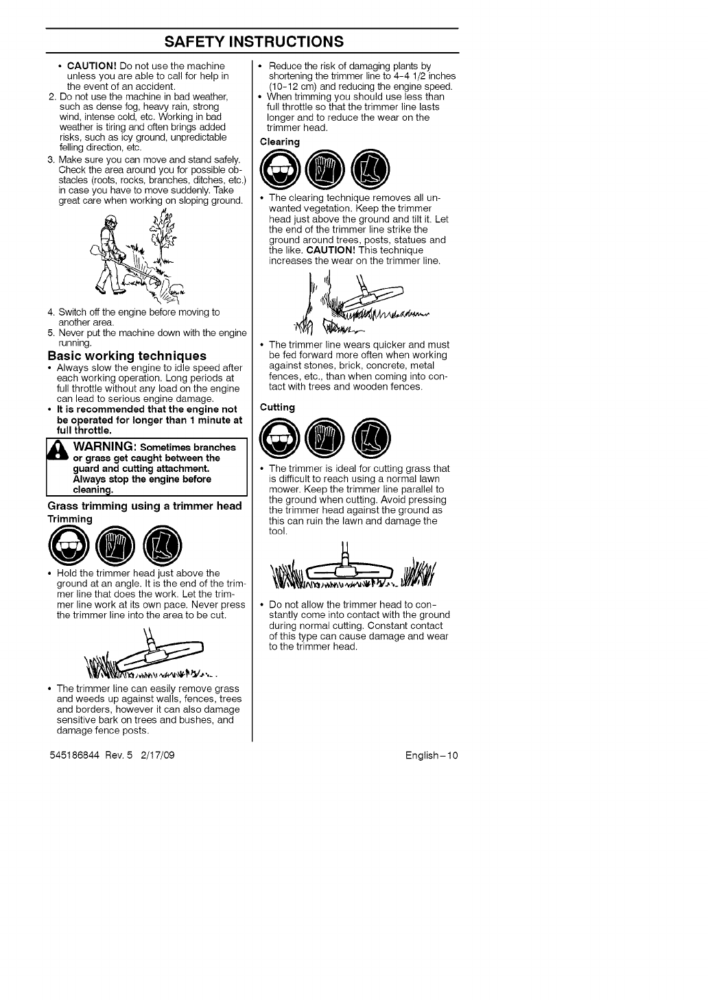
Grass trimming using a trimmer head
Trimming
QOO
• Hold the trimmer head just above the
ground at an angle. It is the end of the trim-
mer line that does the work. Let the trim-
mer line work at its own pace. Never press
the trimmer line into the area to be cut.
• The trimmer line can easily remove grass
and weeds up against walls, fences, trees
and borders, however it can also damage
sensitive bark on trees and bushes, and
damage fence posts.
• Reduce the risk of damaging plants by
shortening the trimmer line to 4-4 1/2 inches
(10-12 cm) and reducing the engine speed.
• When trimming you should use less than
full throttle so that the trimmer line lasts
longer and to reduce the wear on the
trimmer head.
Clearing
QOO
• The clearing technique removes all un-
wanted vegetation. Keep the trimmer
head just above the ground and tilt it. Let
the end of the trimmer line strike the
ground around trees, posts, statues and
the like. CAUTION! This technique
increases the wear on the trimmer line.
• The trimmer line wears quicker and must
be fed forward more often when working
against stones, brick, concrete, metal
fences, etc., than when coming into con-
tact with trees and wooden fences.
Cutting
Q00
• The trimmer is ideal for cutting grass that
is difficult to reach using a normal lawn
mower. Keep the trimmer line parallel to
the ground when cutting. Avoid pressing
the trimmer head against the ground as
this can ruin the lawn and damage the
tool.
Do not allow the trimmer head to con-
stantly come into contact with the ground
during normal cutting. Constant contact
of this type can cause damage and wear
to the trimmer head.
545186844 Rev. 5 2/17/09 English-lO
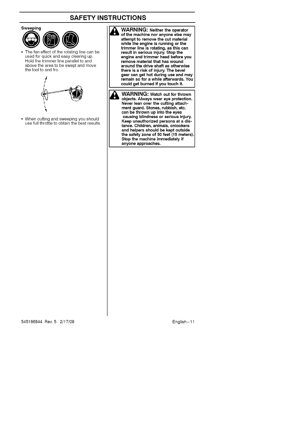
SAFETY INSTRUCTIONS
• The fan effect of the rotating line can be
used for quick and easy clearing up,
Hold the trimmer line parallel to and
above the area to be swept and move
the tool to and fro.
/
/
\
• When cutting and sweeping you should
use full throttle to obtain the best results.
&
&
WARNING: Neither the operator
of the machine nor anyone else may
attempt to remove the cut material
while the engine is running or the
trimmer line is rotating, as this can
result in serious injury. Stop the
engine and trimmer head before you
remove material that has wound
around the drive shaft as otherwise
there is a risk of injury. The bevel
gear can get hot during use and may
remain so for a while afterwards. You
could get burned if you touch it.
WARNING: Watch out for thrown
objects. Always wear eye protection.
Never lean over the cutting attach-
ment guard. Stones, rubbish, etc.
can be thrown up into the eyes
causing blindness or serious injury.
Keep unauthorized persons at a dis-
tance. Children, animals, onlookers
and helpers should be kept outside
the safety zone of 50 feet (15 meters).
Stop the machine immediately if
anyone approaches.
545186844 Rev. 5 2/17/09 English-11
\,
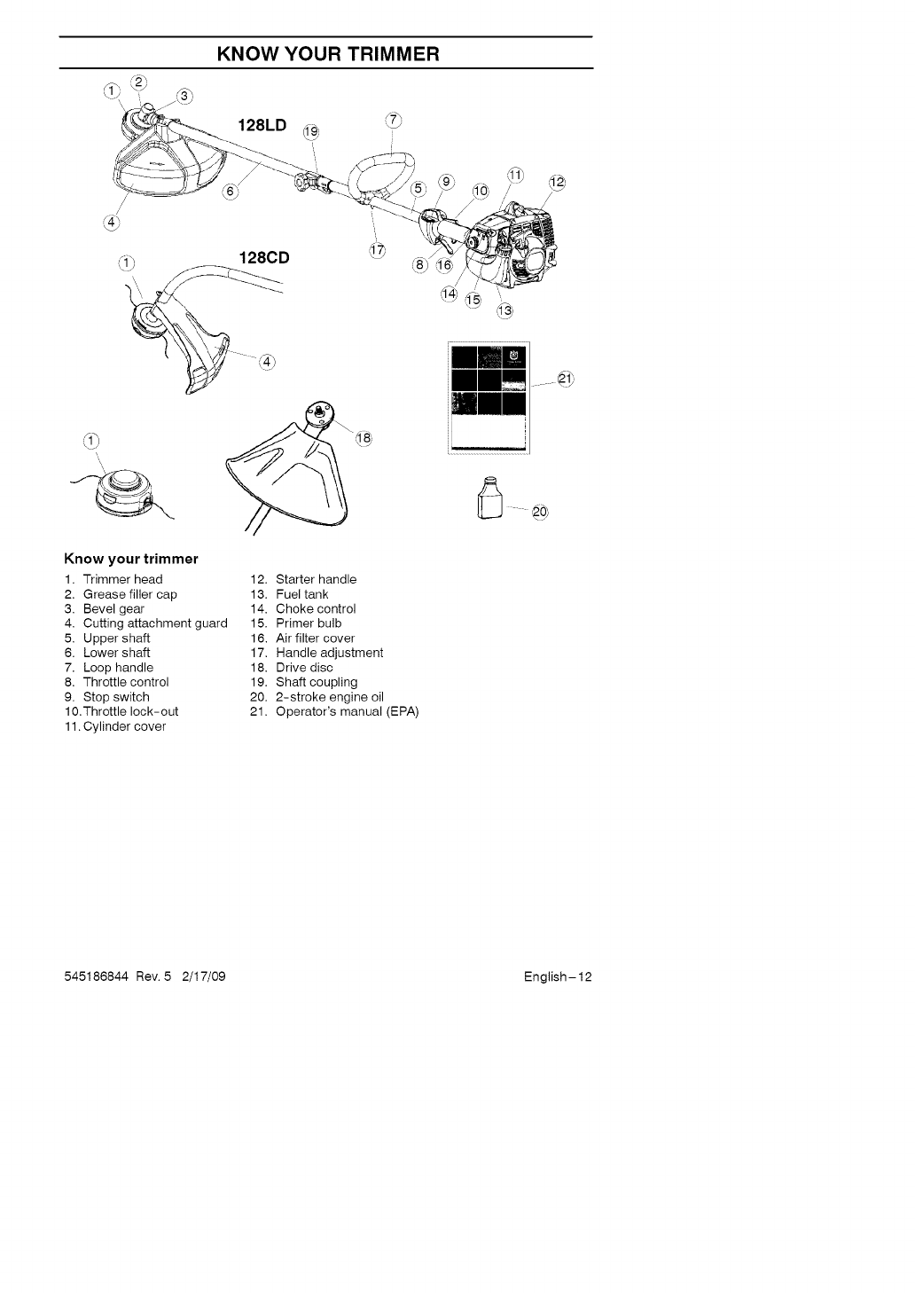
Know your trimmer
1. Trimmer head
2. Grease filler cap
3. Bevel gear
4. Cutting attachment guard
5. Upper shaft
6. Lower shaft
7. Loop handle
8. Throttle control
9. Stop switch
10.Throttle lock-out
11. Cylinder cover
12. Starter handle
13. Fuel tank
14. Choke control
15. Primer bulb
16. Air filter cover
17. Handle adjustment
18. Drive disc
19. Shaft coupling
20. 2-stroke engine oil
21. Operator's manual (EPA)
545186844 Rev. 5 2/17/09 English-12
ASSEMBLY
NOTE: Make sure unit is assembled cor-
rectly as shown in this manual.
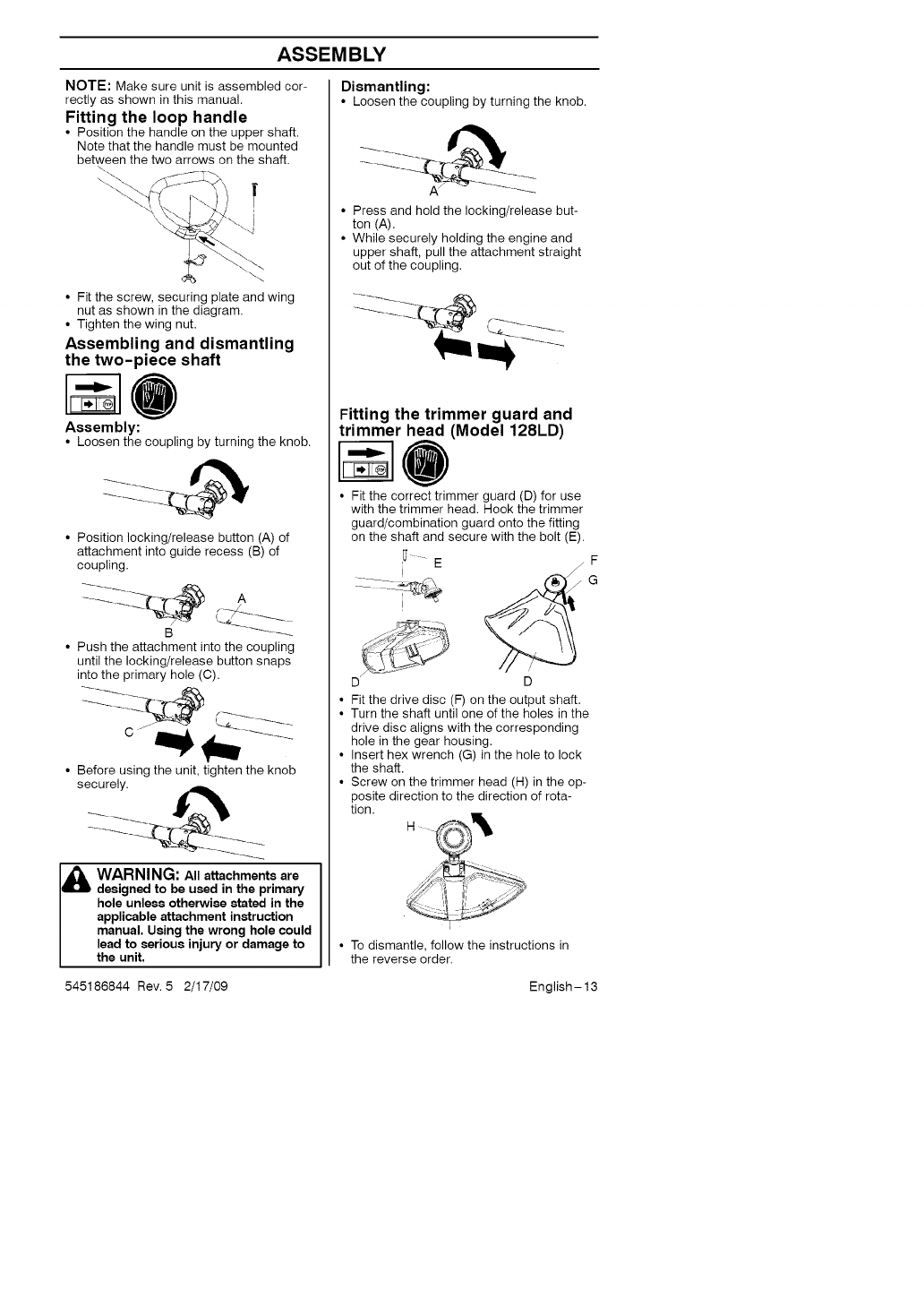
Fitting the loop handle
• Position the handle on the upper shaft.
Note that the handle must be mounted
between the two arrows on the shaft.
I
• Fit the screw, securing plate and wing
nut as shown in the diagram.
• Tighten the wing nut.
Assembling and dismantling
the two-piece shaft
Assembly:
• Loosen the coupling by turning the knob.
• Position locking/release button (A) of
attachment into guide recess (B) of
coupling.
B
• Push the attachment into the coupling
until the locking/release button snaps
into the primary hole (C).
• Before using the unit, tighten the knob
securely.
I& WARNING: All attachments are
designed to be used in the primary
hole unless otherwise stated in the
applicable attachment instruction
manual. Using the wrong hole could
lead to serious injury or damage to
the unit,
545186844 Rev. 5 2/17/09
Dismantling:
• Loosen the coupling by turning the knob.
Press and hold the locking/release but-
ton (A).
While securely holding the engine and
upper shaft, pull the attachment straight
out of the coupling.
Fitting the trimmer guard and
trimmer head (Model 128LD)
• Fit the correct trimmer guard (D) for use
with the trimmer head. Hook the trimmer
guard/combination guard onto the fitting
on the shaft and secure with the bolt (E).
I_ " E /F
i
D D
• Fit the drive disc (F) on the output shaft.
• Turn the shaft until one of the holes in the
drive disc aligns with the corresponding
hole in the gear housing.
• Insert hex wrench (G) in the hole to lock
the shaft.
• Screw on the trimmer head (H) in the op-
posite direction to the direction of rota-
tion.
H
i
• To dismantle, follow the instructions in
the reverse order.
English - 13
ASSEMBLY
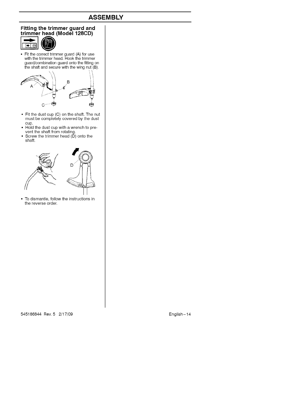
Fitting the trimmer guard and
trimmer head (Model 128CD)
0
• Fit the correct trimmer guard (A) for use
with the trimmer head. Hook the trimmer
guard/combination guard onto the fitting on
the shaft and secure with the wing nut (B).
\\\ jB "IL_/I
c.......÷ ÷
• Fit the dust cup (C) on the shaft. The nut
must be completely covered by the dust
cup.
• Hold the dust cup with a wrench to pre-
vent the shaft from rotating.
• Screw the trimmer head (D) onto the
shaft.
• To dismantle, follow the instructions in
the reverse order.
545186844 Rev. 5 2/17/09 English-14
FUEL HANDLING
Fuel mixture
CAUTION! The machine is equipped with
a two-stroke engine and must always be
run using a mixture of gasoline and two-
stroke engine oil. It is important to accu-
rately measure the amount of oil to be
mixed to ensure that the correct mixture is
obtained. When mixing small amounts of
fuel, even small inaccuracies can drastical-
ly affect the ratio of the mixture.
&WARNING: Always ensure
there is adequate ventilation when
handling fuel.
Gasoline
CAUTION! Always use high quality
unleaded gasoline.
•This engine is certified to operate on
unleaded gasoline.
• The lowest recommended octane rating
is 87. If you run the engine on lower oc-
tane rating than 87, "knocking" can oc-
cur. This leads to an increased engine
temperature, which can result in a seri-
ous engine breakdown.
• When working at continuous high revs a
higher octane rating is recommended.
Two-stroke oil
• For great results and performance use
HUSQVARNA two-stroke oil, which is
specially formulated for our two-stroke
engines. Mixture 1:50 (2%).
• To maximize the life of your trimmer, you
may choose to use a high quality syn-
thetic oil formulated for two-stroke
engines. Mixture 1:50 (2%).
• Never use two-stroke oil intended for
water-cooled outboard engines,
sometimes referred to as outboard oil.
• Never use oil intended for four-stroke
engines.
Gasoline
U.S. gallon
1
21/2
5
Two-stroke oil
2% (1:50)
U.S. fl. oz.
21/2
61/2
127/8
Mixing
• Always mix the gasoline and oil in a
clean container intended for fuel.
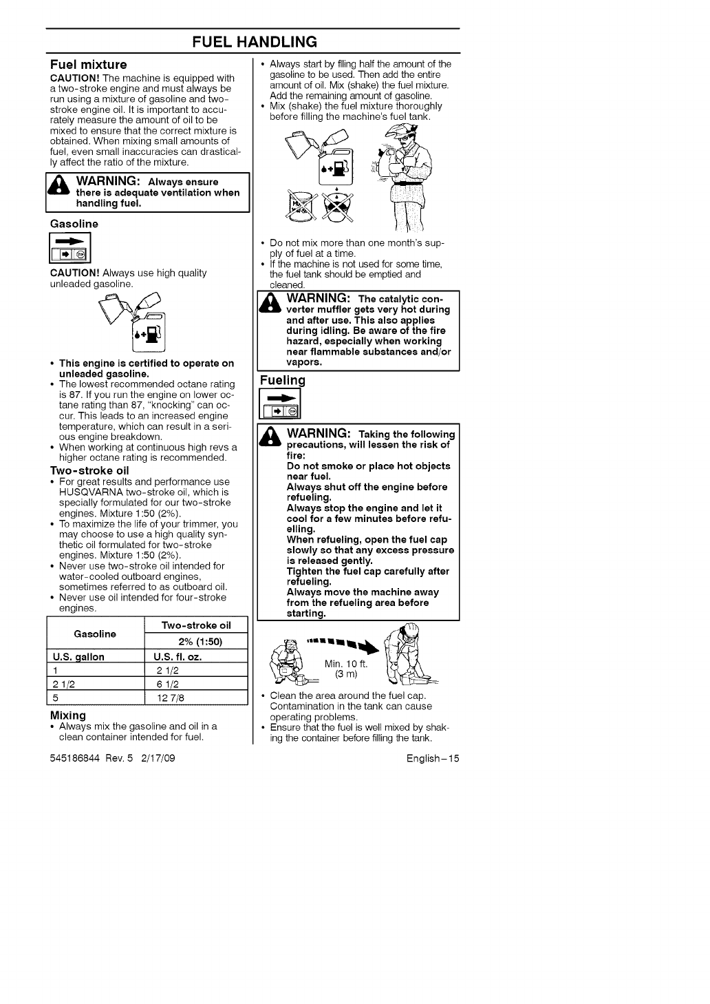
• Always start by filing half the amount of the
gasoline to be used. Then add the entire
amount of oil. Mix (shake) the fuel mixture.
Add the remaining amount of gasoline.
• Mix (shake) the fuel mixture thoroughly
before filling the machine's fuel tank.
• Do not mix more than one month's sup-
ply of fuel at a time.
• If the machine is not used for some time,
the fuel tank should be emptied and
cleaned.
WARNING: The catalytic con-
verter muffler gets very hot during
and after use. This also applies
during idling. Be aware of the fire
hazard, especially when working
near flammable substances and/or
vapors.
Fueling
WARNING: Taking the following
precautions, will lessen the risk of
fire:
Do not smoke or place hot objects
near fuel.
Always shut off the engine before
refueling.
Always stop the engine and let it
cool for a few minutes before refu-
elling.
When refueling, open the fuel cap
slowly so that any excess pressure
is released gently.
Tighten the fuel cap carefully after
refueling.
Always move the machine away
from the refueling area before
starting.
• Clean the area around the fuel cap.
Contamination in the tank can cause
operating problems.
• Ensure that the fuel is well mixed by shak-
ing the container before filling the tank.
545186844 Rev. 5 2/17/09 English-15
STARTING AND STOPPING
Check before starting
• Inspect the unit before each use. Re-
place damaged parts. Check for fuel
leaks. Make sure all fasteners are in
place and secure. Make sure the cutting
attachment is properly installed and se-
curely fastened. Use only flexible, non-
metallic line recommended by the
manufacturer. Never use, for example,
wire or wire rope, which can break off
and become a dangerous projectile.
• Check that the trimmer head and trimmer
guard are not damaged or cracked.
Replace the trimmer head or trimmer
guard if they have been exposed to
impact or are cracked.
• Never use the machine without a guard
nor with a defective guard.
Starting and stopping
QOO
WARNING: The complete clutch,
clutch cover, and shaft must be
fitted before the machine is started,
otherwise parts could come loose
and cause personal injury.
Always move the machine away
from the refueling area before
starting. Place the machine on a
flat surface. Ensure the cutting at-
tachment cannot come into contact
with any object.
Make sure no unauthorized persons
are in the working area, otherwise
there is a risk of serious personal
injury. The safety distance is 50 feet
(15 meters).
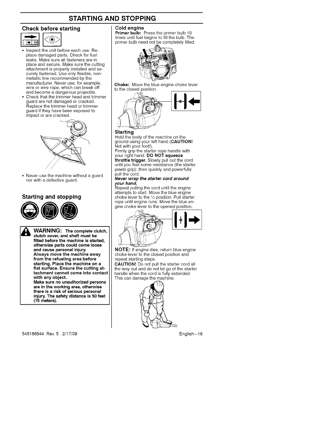
Cold engine
Primer bulb: Press the primer bulb 10
times until fuel begins to fill the bulb. The
primer bulb need not be completely filled.
',\\ y-
Choke: Move the blue engine choke lever
to the closed position.
/ t
\_', i
I _ '_',t!.,i J
J ¢C)t¢_ JY
Starting
Hold the body of the machine on the
ground using your left hand (CAUTION!
Not with your foot!).
Firmly grip the starter rope handle with
your right hand. DO NOT squeeze
throttle trigger, Slowly pull out the cord
until you feel some resistance (the starter
pawls grip); then quickly and powerfully
pull the cord.
Never wrap the starter cord around
your hand.
Repeat pulling the cord until the engine
attempts to start. Move the blue engine
choke lever to the 1/2position. Pull starter
rope until engine runs. Move the blue en-
gine choke lever to the opened position.
/ t
} _ '_',t!.,i J
NOTE; If engine dies, return blue engine
choke lever to the closed position and
repeat starting steps.
CAUTION! Do not pull the starter cord all
the way out and do not let go of the starter
handle when the cord is fully extended.
This can damage the machine.
545186844 Rev. 5 2/17/09 English-16
STARTING AND STOPPING
Warm engine
With a warm engine, move the blue engine
choke lever to the 1/2position. Pull starter
rope until engine runs. Move the blue
engine choke lever to the opened position.
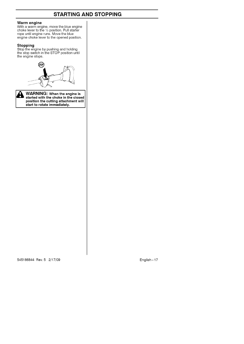
Stopping
Stop the engine by pushing and holding
the stop switch in the STOP position until
the engine stops.
&WARNING: When the engine is
started with the choke in the closed
position the cutting attachment will
start to rotate immediately.
545186844 Rev. 5 2/17/09 English-17
MAINTENANCE
The owner is responsible for the perfor-
mance of all required maintenance as
defined in the operator's manual.
Carburetor
Your Husqvarna product has been designed
and manufactured to specifications that re-
duce harmful emissions. After the engine
has used 8-10 tanks of fuel, the engine will
be run-in. To ensure that it continues to run
at peak performance and to minimize harm-
ful exhaust emissions after the run-in peri-
od, ask your servicing dealer to adjust your
carburetor.
&WARNING: The complete clutch,
clutch cover, and shaft must be
fitted before the machine is started,
otherwise parts could come loose
and cause personal injury.
Function
• The carburetor governs the engine's
speed via the throttle control. Air and fuel
are mixed in the carburetor.
• The T-screw regulates the throttle setting
at idle speed. If the T-screw is turned
clockwise this gives a higher idle speed;
turning it counterclockwise gives a lower
idle speed.
Basic setting
• The basic carburetor settings are ad-
justed during testing at the factory. Fine
adjustment should be carried out by a
skilled technician.
CAUTION! If the cutting attachment rotates
when the engine is idling the idle adjustment
screw T should be turned counterclockwise
until the cutting attachment stops.
Rec. idle speed:
See "Technical data" section.
Recommended max. speed:
See "Technical data" section.
_WARNING: If the idle speed
cannot be adjusted so that the cut-
ting attachment stops, contact your
dealer/service workshop. Do not use
the machine until it has been cor-
rectly adjusted or repaired.
Fine adjustment of the idle speed-T
Adjust the idle speed using the idle adjust-
ment screw-T if it is necessary to readjust.
First, turn the idle adjustment screw-T
clockwise until the cutting attachment starts
to rotate. Then, turn the screw counterc-
lockwise until the cutting attachment stops.
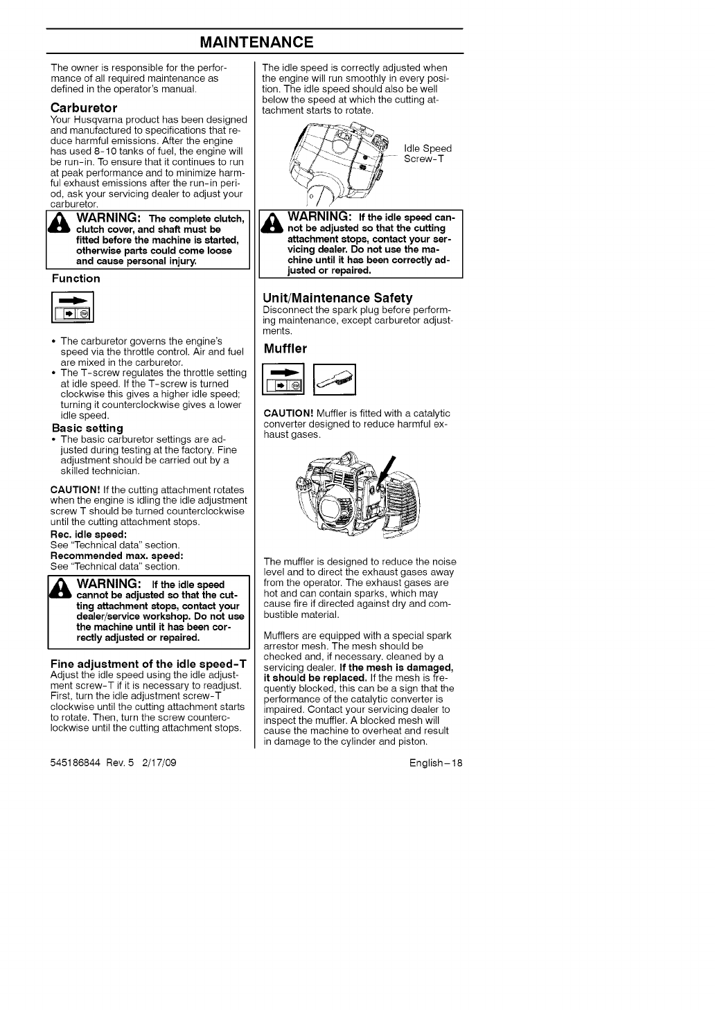
The idle speed is correctly adjusted when
the engine will run smoothly in every posi-
tion. The idle speed should also be well
below the speed at which the cutting at-
tachment starts to rotate.
Idle Speed
Screw-T
WARNING: If the idle speed can-
not be adjusted so that the cutting
attachment stops, contact your ser-
vicing dealer. Do not use the ma-
chine until it has been correctly ad-
justed or repaired.
Unit/Maintenance Safety
Disconnect the spark plug before perform-
ing maintenance, except carburetor adjust-
ments.
Muffler
CAUTION! Muffler is fitted with a catalytic
converter designed to reduce harmful ex-
haust gases.
The muffler is designed to reduce the noise
level and to direct the exhaust gases away
from the operator. The exhaust gases are
hot and can contain sparks, which may
cause fire if directed against dry and com-
bustible material.
Mufflers are equipped with a special spark
arrestor mesh. The mesh should be
checked and, if necessary, cleaned by a
servicing dealer. If the mesh is damaged,
it should be replaced. If the mesh is fre-
quently blocked, this can be a sign that the
performance of the catalytic converter is
impaired. Contact your servicing dealer to
inspect the muffler. A blocked mesh will
cause the machine to overheat and result
in damage to the cylinder and piston.
545186844 Rev. 5 2/17/09 English-18
MAINTENANCE
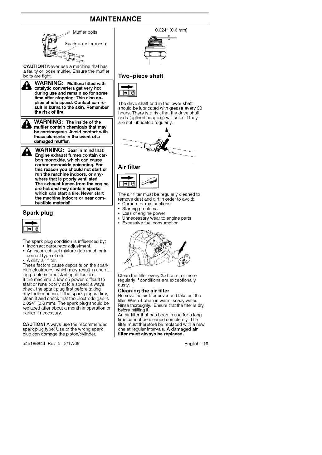
Muffler bolts
Spark arrestor mesh
jJ
CAUTION! Never use a machine that has
a faulty or loose muffler. Ensure the muffler
bolts are tight.
I_ ARNING: Mufflers fitted with
catalytic converters get very hot
during use and remain so for some
time after stopping. This also ap-
plies at idle speed. Contact can re-
sult in burns to the skin. Remember
the risk of fire!
I_ ARNING: The inside of the
muffler contain chemicals that may
be carcinogenic, Avoid contact with
these elements in the event of a
damaged muffler.
_ARNING: Bear in mind that:
Engine exhaust fumes contain car-
bon monoxide, which can cause
carbon monoxide poisoning. For
this reason you should not start or
run the machine indoors, or any-
where that is poorly ventilated.
The exhaust fumes from the engine
are hot and may contain sparks
which can start a fire, Never start
the machine indoors or near com-
bustible material!
Spark plug
The spark plug condition is influenced by:
• Incorrect carburetor adjustment.
• An incorrect fuel mixture (too much or in-
correct type of oil).
• A dirty air filter.
These factors cause deposits on the spark
plug electrodes, which may result in operat-
ing problems and starting difficulties.
If the machine is low on power, difficult to
start or runs poorly at idle speed: always
check the spark plug first before taking
any further action. If the spark plug is dirty,
clean it and check that the electrode gap is
0.024" (0.6 mm). The spark plug should be
replaced after about a month in operation or
earlier if necessary.
CAUTION! Always use the recommended
spark plug type! Use of the wrong spark
plug can damage the piston/cylinder.
0.024" (0.6 mm)
Two-piece shaft
The drive shaft end in the lower shaft
should be lubricated with grease every 30
hours. There is a risk that the drive shaft
ends (splined coupling) will seize if they
are not lubricated regularly.
ii
Air filter
The air filter must be regularly cleaned to
remove dust and dirt in order to avoid:
• Carburetor malfunctions
• Starting problems
• Loss of engine power
• Unnecessary wear to engine parts
• Excessive fuel consumption
Clean the filter every 25 hours, or more
regularly if conditions are exceptionally
dusty.
Cleaning the air filter
Remove the air filter cover and take out the
filter. Wash it clean in warm, soapy water.
Rinse thoroughly. Ensure that the filter is dry
before refitting it.
An air filter that has been in use for a long
time cannot be cleaned completely. The
filter must therefore be replaced with a new
one at regular intervals. A damaged air
filter must always be replaced,
545186844 Rev. 5 2/17/09 English-19
MAINTENANCE
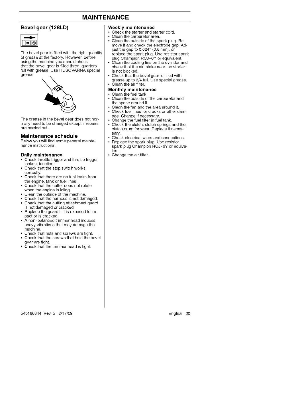
Bevel gear (128LD)
The bevel gear is filled with the right quantity
of grease at the factory. However, before
using the machine you should check
that the bevel gear is filled three-quarters
full with grease. Use HUSQVARNA special
grease.
The grease in the bevel gear does not nor-
mally need to be changed except if repairs
are carried out.
Maintenance schedule
Below you will find some general mainte-
nance instructions.
Daily maintenance
•Check throttle trigger and throttle trigger
lockout function.
• Check that the stop switch works
correctly.
• Check that there are no fuel leaks from
the engine, tank or fuel lines.
• Check that the cutter does not rotate
when the engine is idling.
• Clean the outside of the machine.
• Check that the harness is not damaged.
• Check that the cutting attachment guard
is not damaged or cracked.
• Replace the guard if it is exposed to im-
pact or is cracked.
• A non-balanced trimmer head induces
heavy vibrations that may damage the
machine.
• Check that nuts and screws are tight.
• Check that the screws that hold the bevel
gear are tight.
• Check that the trimmer head is tight.
Weekly maintenance
• Check the starter and starter cord.
• Clean the carburetor area.
• Clean the outside of the spark plug. Re-
move it and check the electrode gap. Ad-
just the gap to 0.024" (0.6 mm), or
replace the spark plug. Use resistor spark
plug Champion RCJ-6Y or equivalent.
• Clean the cooling fins on the cylinder and
check that the air intake near the starter
is not blocked.
• Check that the bevel gear is filled with
grease up to 3/4 full. Use special grease.
• Clean the air filter.
Monthly maintenance
• Clean the fuel tank.
• Clean the outside of the carburetor and
the space around it.
• Clean the fan and the area around it.
• Check fuel lines for cracks or other dam-
age. Change if necessary.
• Change the fuel filter in fuel tank.
• Check the clutch, clutch springs and the
clutch drum for wear. Replace if neces-
sary.
• Check electrical wires and connections.
• Replace the spark plug. Use resistor
spark plug Champion RCJ-6Y or equiva-
lent.
• Change the air filter.
545186844 Rev. 5 2/17/09 English-20
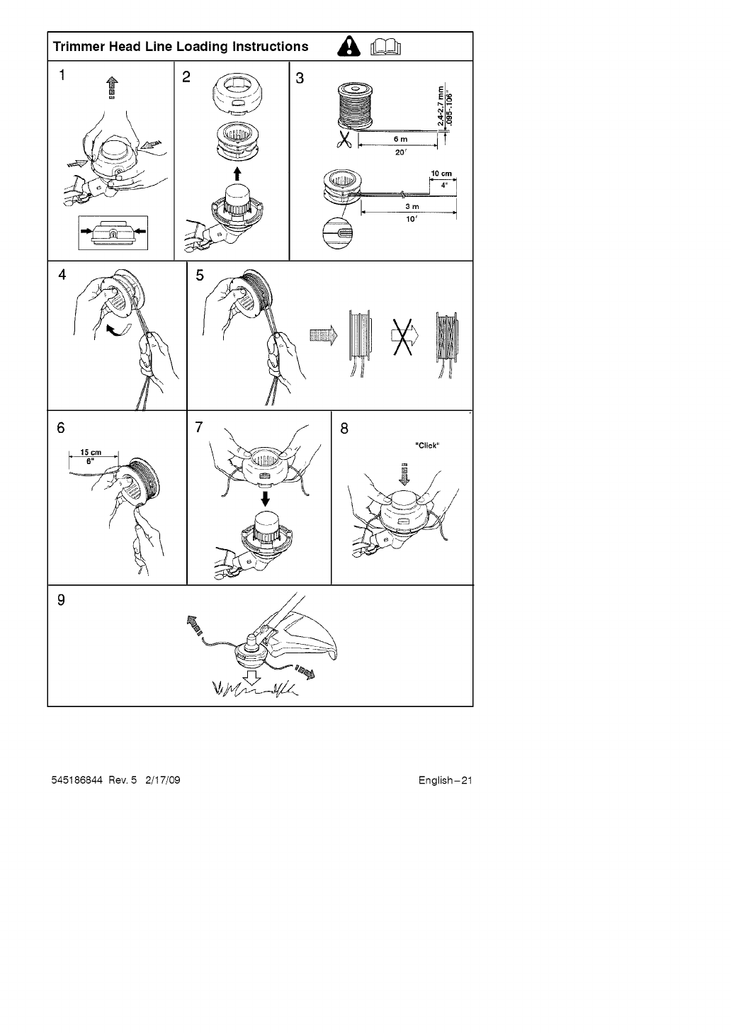
Trimmer Head Line Loading Instructions
4
t
_8
20'
J
78
"Click"
545186844 Rev. 5 2/17/09 English-21

TECHNICAL DATA
Technical data
1280D 128LD
Engine
Cylinder volume, cu.in./cm 3 1.7/28 1.7/28
Cylinder bore, inch/mm 1.4/35 1.4/35
Stroke, inch/mm 1.130/28.7 1.130/28.7
Idle speed, rpm 2,800-3,200 2,800-3,200
Recommended max. speed, rpm 10,000 11,000
Speed of output shaft, rpm 8,000 8,000
Max. engine output, acc. to ISO 8893, hp/kW 1.1/0.8 1.1/0.8
Catalytic converter muffler Yes Yes
Speed-regulated ignition system Yes Yes
Ignition system
Manufacturer/type of ignition system Walbro/CD Walbro/CD
Spark plug Champion Champion
RCJ-6Y RCJ-6Y
0.024/0.6 0.024/0.6
Electrode gap, inch/mm
Fuel and lubrication system
Manufacturer/type of carburetor Zama Zama
Fuel tank capacity, US pint/liter 0.85/0.4 0.85/0.4
Weight
Weight without fuel, cutting attachment and guard, Ibs/kg 10/4.4 11/4.8
Sound levels (see note 1)
Equivalent sound pressure level at the user's ear,
measured according to ANSI B175.3-1997, dB(A), min/max: 94/97 94/97
Vibration levels
Vibration levels at handles, measured according to ANSI
B175.3-1997, m/s 2
At idle, left/right handles: 3/5 3/5
At max. speed, left/right handles: 9/8 9/8
Note 1: Equivalent noise pressure level is calculated as the time-weighted energy total for
noise pressure levels under various working conditions with the following time distribution:
1/2 idle and 1/2 max. speed.
NOTE! Noise pressure at the user's ear and vibration on the handles are measured with all the
machine's approved cutting equipment fitted. The table indicates the highest and lowest values.
These attachments used in combination with the specified powerhead have been evaluated
to ANSI B175.3-2003, "Grass Trimmers and Brushcutters - Safety Requirements". These
combinations have been evaluated by Underwriter's Laboratories Inc. (UL) and are conse-
quently UL listed:
Model 1280D (3/8 RH arbor shaft thread)
Approved accessories TY.LT..yE_ 1 Cutting attachment/ guard, part. no.
Tr mmer head --ITNG7 [ 537 41 92-14 /545 03 11-01
Model 128LD (M10 LH arbor shaft thread)
Approved accessories Type Cutting attachment /guard, part. no.
Trimmer head T25 537 33 83-06 /545 03 09-01
Plastic blades Tricut 300 mm 531 00 38-11 /545 03 09-01
These accessories used in combination with the specified powerheads have been evaluat-
ed to applicable ISO- and EN safety requirement standards by the Swedish Machinery
Testing Institute:
Attachments
Edger attachment with shaft
Cultivator attachment with shaft
Blower attachment with shaft
Brushcutter attachment with shaft
Pruner attachment with shaft
Part. no.
952 711 607
952 711 608
952 711 609
952 711 610
952 711 612
545186844 Rev. 5 2/17/09 English-22
WARRANTY STATEMENT
SECTION 1: LIMITED WARRANTY
Huaqvarna warrants Husqvarna product to
the original purchaser to be free from defects
in material and workmanship from the date of
purchase for the "Warranty Period" of the
products as set forth below:
Lifetime Warranty: Trimmer shafts, ignition
coils and modules.
2 Year NON-COMMERCIAL Warranty:
Trimmers for non-commercial, non-profes-
sional, non-institutional or non-income pro-
ducing use, except as herein stated.
Emission control system components neces-
sary to comply with CARB and EPA regula-
tions.
1 Year Warranty: All trimmers used for
commercial, institutional, professional, or in-
come producing purposes or use.
SECTION 2: HUSQVARNA'S OB-
LIGATIONS UNDER THE WARRANTY
Husqvarna will repair or replace defective
components without charge for parts or labor
a component fails because of a defect in
material or workmanship during the warranty
period.
SECTION 3: ITEMS NOT COVERED
BY THIS WARRANTY
The following items are not covered by this
warranty:
(1) Normal customer maintenance items
which become worn through normal regu-
lar use, including, but not limited to, filters,
lubricants, rewind springs, spark plugs,
and starter ropes.
(2) Natural discoloration of material due to
ultraviolet light.
SECTION 4: EXCEPTIONS AND
LIMITATIONS
This warranty shall be inapplicable to de-
fects resulting from the following:
(1) Accident, abuse, misuse, negligence and
neglect, including stale fuel, dirt, abra-
sives, moisture, rust, corrosion, or any
adverse reaction due to incorrect storage
or use habits.
(2) Failure to operate or maintain the unit in
accordance with the operator's manual or
instruction sheet furnished by Husqvarna.
(3) Alterations or modifications that change
the intended use of the product or affects
the product's performance, operation,
safety, or durability, or causes the product
to fail to comply with any applicable laws.
(4) Additional damage to parts or compo-
nents due to continued use occurring af-
ter any of the above.
REPAIR OR REPLACEMENT AS PRO-
VIDED UNDER THIS WARRANTY IS THE
EXCLUSIVE REMEDY OF THE PURCHAS-
ER. HUSQVARNA SHALL NOT BE LIABLE
FOR ANY INCIDENTAL OR CONSEQUEN-
TIAL DAMAGES FOR BREACH OF ANY
EXPRESS OR IMPLIED WARRANTY ON
THESE PRODUCTS EXCEPT TO THE EX-
TENT PROHIBITED BY APPLICABLE LAW.
ANY IMPLIED WARRANTY OR MER-
CHANTABILITY OR FITNESS FOR A PAR-
TICULAR PURPOSE ON THESE PROD-
UCTS IS LIMITED IN DURATION TO THE
WARRANTY PERIOD AS DEFINED IN THE
LIMITED WARRANTY STATEMENT HUSQ-
VARNA RESERVES THE RIGHT TO
CHANGE OR IMPROVE THE DESIGN OF
THE PRODUCT WITHOUT NOTICE, AND
DOES NOT ASSUME OBLIGATION TO UP-
DATE PREVIOUSLY MANUFACTURED
PRODUCTS.
Some states do not allow the exclusion of in-
cidental or consequential damages, or limita-
tions on how long an implied warranty lasts,
so the above limitations or exclusions may not
apply to you. This warranty gives you specific
legal rights, and you may also have other
rights which vary from state to state.
SECTION 5: CUSTOMER RE-
SPONSIBILITIES
The product must exhibit reasonable care,
maintenance, operation, storage and gener-
al upkeep as written in the maintenance
section of the operator's manual. Should an
operational problem or failure occur, the
product should not be used, but delivered
as is to an authorized Husqvarna dealer for
evaluation. Proof of purchase, as explained
in Section 6, rests solely with the customer.
SECTION 6: PROCEDURE TO OB-
TAIN WARRANTY CONSIDERATION
It is the Owner's and Dealer's responsibility to
make certain that the Warranty Registration
Card is properly filled out and mailed to Husq-
varna. This card should be mailed within ten
(10) days from the date of purchase in order
to confirm the warranty and to facilitate post-
sale service.Proof of purchase must be pre-
sented to the authorized Husqvarna dealer in
order to obtain warranty service. This proof
must include date purchased, model number,
serial number, and complete name and ad-
dress of the selling dealer.To obtain the benefit
of this warranty, the product believed to be
defective must be delivered to an authorized
Husqvarna dealer in a timely manner, no later
than thirty (30) days from date of the opera-
tional problem or failure. The product must be
delivered at the owner's expense. Pick-up
and delivery charges are not covered by this
warranty. An authorized Husqvarna dealer
can be normally located through the "Yellow
Pages" of the local telephone directory or by
calling 1-800-438-7297 for a dealer in your
area.
6 Husqvarna
7349 Stateaville Road
CHARLOTTE, NO 28269
545186844 Rev. 5 2/17/09 English-23

U.S. EPA /CALIFORNIA /ENVIRONMENT CANADA
EMISSION CONTROL WARRANTY STATEMENT
YOUR WARRANTY RIGHTS AND
OBLIGATIONS:
The U.S. Environmental Protection Agency,
California Air Resources Board, Environment
Canada and HUSQVARNA are pleased to
explain the emissions control system warranty
on your year 2009 and later small off-road
engine. In California, all small off-road en-
gines must be designed, built, and equipped
to meet the State's stringent anti-smog stan-
dards. HUSQVARNA must warrant the emis-
sion control system on your small off-road
engine for the periods of time listed below pro-
vided there has been no abuse, neglect, or
improper maintenance of your small off-road
engine. Your emission control system includes
parts such as the carburetor, the ignition sys-
tem and the fuel tank. Where a warrantable
condition exists, HUSQVARNA will repair your
small off-road engine at no cost to you. Ex-
penses covered under warranty include diag-
nosis, parts and labor.
MANUFACTURER'S WARRANTY
COVERAGE:
If any emissions related part on your engine
(as listed under Emissions Control Warran-
ty Parts List) is defective or a defect in the
materials or workmanship of the engine
causes the failure of such an emission re-
lated part, the part will be repaired or re-
placed by HUSQVARNA.
OWNER'S WARRANTY RESPONSI-
BILITIES:
As the small off-road engine owner, you are
responsible for the performance of the re-
quired maintenance listed in your operator's
manual. HUSQVARNA recommends that
you retain all receipts covering maintenance
on your small off-road engine, but HUSQ-
VARNA cannot deny warranty solely for the
lack of receipts or for your failure to ensure
the performance of all scheduled mainte-
nance. As the small off-road engine owner,
you should be aware that HUSQVARNA
may deny you warranty coverage if your
small off-road engine or a part of it has
failed due to abuse, neglect, improper main-
tenance, unapproved modifications, or the
use of parts not made or approved by the
original equipment manufacturer. You are
responsible for presenting your small off-
road engine to a HUSQVARNA authorized
repair center as soon as a problem exists.
Warranty repairs should be completed in a
reasonable amount of time, not to exceed
30 days. If you have any questions regard-
ing your warranty rights and responsibilities,
you should contact your nearest authorized
service center, call HUSQVARNA at
1-800-487-5951, or visit www.usa.
husqvarna.com.
WARRANTY COMMENCEMENT
DATE:
The warranty period begins on the date the
small off-road engine is purchased.
LENGTH OF COVERAGE:
This warranty shall be for a period of two
years from the initial date of purchase.
WHAT IS COVERED: REPAIR OR
REPLACEMENT OF PARTS,
Repair or replacement of any warranted part
will be performed at no charge to the owner at
an approved HUSQVARNA servicing center.
If you have any questions regarding your war-
rarity rights and responsibilities, you should
contact your nearest authorized service cen-
ter, call HUSQVARNA at 1-800-487-5951 or
visit www.usa.husqvama.com.
WARRANTY PERIOD:
Any warranted part which is not scheduled
for replacement as required maintenance,
or which is scheduled only for regular in-
spection to the effect of "repair or replace
as necessary" shall be warranted for 2
years. Any warranted part which is sched-
uled for replacement as required mainte-
nance shall be warranted for the period of
time up to the first scheduled replacement
point for that part.
DIAGNOSIS:
The owner shall not be charged for diag-
nostic labor which leads to the determina-
tion that a warranted part is defective if the
diagnostic work is performed at an ap-
proved HUSQVARNA servicing center.
CONSEQUENTIAL DAMAGES:
HUSQVARNA may be liable for damages to
other engine components caused by the fail-
ure of a warranted part still under warranty.
WHAT IS NOT COVERED:
All failures caused by abuse, neglect, or
improper maintenance are not covered.
ADD-ON OR MODIFIED PARTS:
The use of add-on or modified parts can be
grounds for disallowing a warranty claim.
HUSQVARNA is not liable to cover failures
of warranted parts caused by the use of
add-on or modified parts.
HOW TO FILE A CLAIM:
If you have any questions regarding your
warranty rights and responsibilities, you
should contact your nearest authorized ser-
vice center or call HUSQVARNA at
1-800-487-5951 or visit www.usa.husqvarna.
oom.
WHERE TO GET WARRANTY SER-
VICE:
Warranty services or repairs shall be pro-
vided at all HUSQVARNA service centers.
Call 1-800-487-5951 or visit www.usa.
husqvarna.com.
545186844 Rev. 5 2/17/09 English-24

U.S. EPA /CALIFORNIA /ENVIRONMENT CANADA
EMISSION CONTROL WARRANTY STATEMENT
MAINTENANCE, REPLACEMENT
AND REPAIR OF EMISSION RE-
LATED PARTS:
Any HUSQVARNA approved replacement
part used in the performance of any warran-
ty maintenance or repair on emission re-
lated parts will be provided without charge
to the owner if the part is under warranty.
EMISSION CONTROL WARRANTY
PARTS LIST:
Carburetor, Air Filter (covered up to mainte-
nance schedule), Ignition System: Spark
Plug (covered up to maintenance sched-
ule), Ignition Module, Muffler including Cata-
lyst (if equipped), Fuel Tank.
MAINTENANCE STATEMENT:
The owner is responsible for the perfor-
mance of all required maintenance as de-
fined in the operator's manual.
This engine is certified to be emissions compliant for the following use:
[] Moderate (50 hours)
[] Intermediate (125 hours)
[] Extended (300 hours)
545186844 Rev. 5 2/17/09 English-25
CONTENIDO
Contenido
CONTENIDO
Contenido ....................... 50
Antes de arrancar, observe Io siguiente: 50
IDENTIFICACION DE SIMBOLOS
Simbolos ........................ 51
INSTRUCClONES DE SEGURIDAD
Equipo de protecci6n personal ...... 52
Equipo de seguridad de la mAquina .. 52
Equipo de corte ................... 53
Control, mantenimiento y servicio del
equipo del seguridad de la mAquina .. 54
Instrucciones generales de seguridad 56
Seguridad de arranque ............. 57
Seguridad en el uso del combustible .57
Transporte y almacenamiento ....... 57
Instrucciones generales de trabajo... 58
Reglas bAsicas de seguridad ....... 58
Tecnica bAsicas de trabajo ......... 58
CONOZCA SU APARATO
Conozca su aparato ............... 60
MONTAJE
Montaje del mango de tipo cerrado... 61
Montaje y desmontaje del tubo divisible 61
Montaje de la protector y la
cabezal de corte .................. 61
MANIPULAClON DEL COMBUSTIBLE
Carburante ...................... 63
Repostaje ....................... 64
ARRANQUE Y PARADA
Control antes de arrancar .......... 65
Arranque y parada ................ 65
MAINTENIMIENTO
Carburador ...................... 67
Silenciador ....................... 67
Bujia ............................ 88
Tube divisible .................... 68
Filtro de aire ..................... 68
Engranaje angulado ............... 69
Programa de mantenimiento ........ 69
Reemplazo de la linea en el
cabezal de corte .................. 70
DATOS TEONIOOS
Datos tecnicos ................... 71
DECLARAOION DE GARANTIA .... 72
DECLARACION DE GARANTIA DE
CONTROL DE EMISION .......... 73
Antes de arrancar, observe Io
siguiente:
Husqvarna AB trabaja constantemente para
perfeccionar sus productos y se reserva, per
Io tanto, el derecho a introducir modifica-
ciones en la construcci6n y el disefio sin
previo aviso. La exposici6n prolongada al
ruido puede causar dafios cr6nicos en el
oido. Use siempre protectores auriculares
homologados. El mantenimiento, el reempla-
zo, o la reparaci6n de los dispositivos del
control de emisi6n y el sistema se pueden
realizar por cualquier establecimiento o indi-
viduo de la reparaci6n del motor para uso
fuera de carretera. El periodo de conformi-
dad de las emisiones referido en la etiqueta
de las emisiones indica el n0mero de las
horas de funcionamiento para las cuales el
motor se ha comprovado para satisfacer re-
quisitos federales de las emisiones.
545186844 Rev. 5 2/17/09
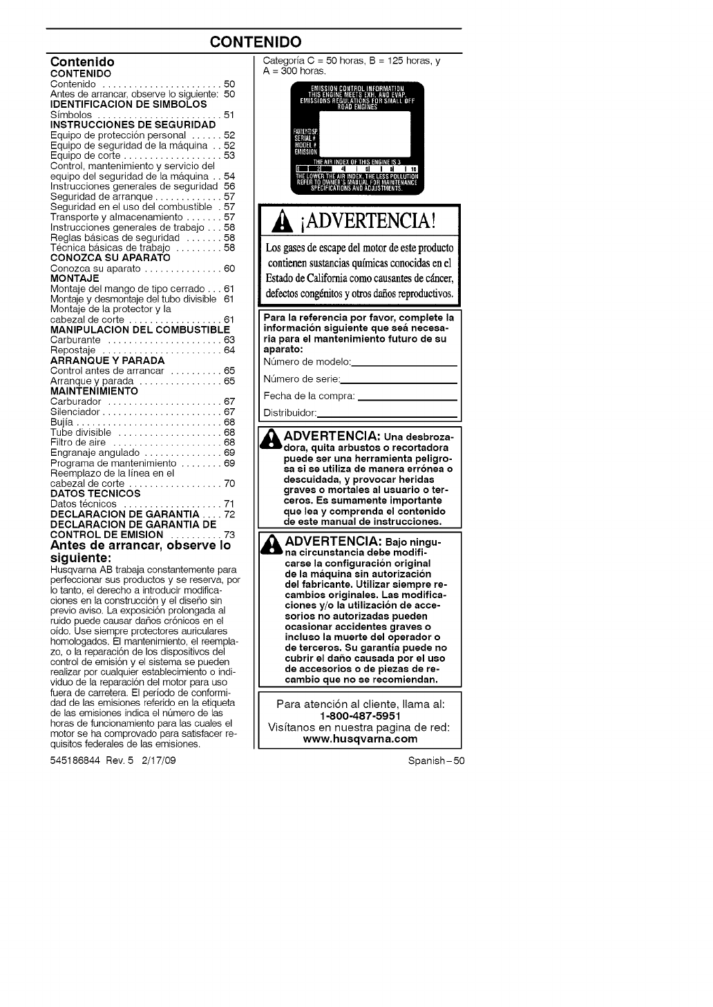
Categoria C = 50 horas, B = 125 horas, y
A = 300 horas.
.& iADVERTENCIA!
Losgasesdeescapedel motordeesteproducto
contienensustanciasqufmicasconocidasen el
Estadode Californiacomocausantesdec,Sncer,
defectoscong6nitosyotrosdafiosreproductivos.
Para la referencia por favor, complete la
informacion eiguiente que eea neceea-
ria para el mantenimiento futuro de eu
aparato:
NOmero de modelo:
NOmero de serie:
Fecha de la compra:
Distribuidor:
ADVERTENCIA: Una deebroza-
dora, quita arbuetoe o recortadora
puede eer una herramienta peligro-
ea ei ee utiliza de manera erronea o
deecuidada, y provocar heridae
graves o mortalee al ueuario o ter-
ceroe. Ee eumamente importante
que lea y comprenda el contenido
de este manual de instruccionee.
ADVERTENCIA: Bajo ningu-
na circunetancia debe modifi-
caree la configuracion original
de la m_,quina sin autorizacion
del fabricante. Utilizar eiempre re-
cambioe originalee. Lae modifica-
cionee y/o la utilizacion de acce-
eorioe no autorizadae pueden
ocaeionar accidentee graves o
inclueo la muerte del operador o
de terceroe. Su garantla puede no
cubrir el dafio caueada por el ueo
de acceeorioe o de piezae de re-
cambio que no ee recomiendan.
Para atenci6n al cliente, llama al:
1-800-487-5951
Visitanos en nuestra pagina de red:
www, husqvarna,oom
Spanish-50
IDENTIFICACION DE SIMBOLOS
Simbolos
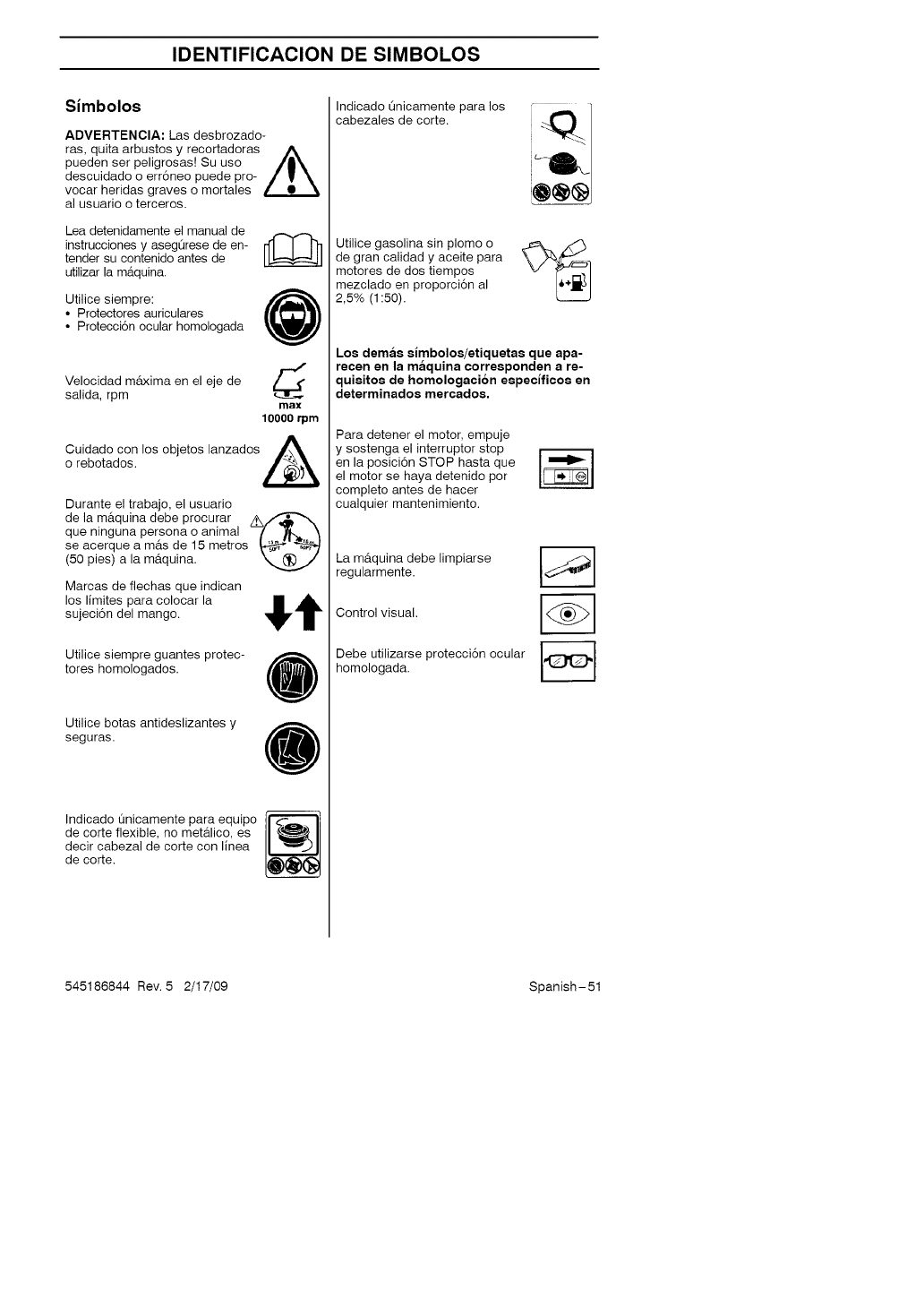
ADVERTENCIA: Las desbrozado-
ras, quita arbustos y recortadoras b_,
pueden ser peligrosas[ Su uso J|_
descuidado o err6neo puede pro- /_
vocar heridas graves o mortales
al usuario o terceros.
Lea detenidamente el manual de
instrucciones y asegQrese de en-
tender su contenido antes de
utilizar la m&quina.
Utilice siempre: @
• Protectores auriculares
• Protecci6n ocular homologada
Velocidad m&xima en el eje de d
salida, rpm max
10000 rpm
A
Cuidado con los objetos lanzados L,&_ '
o rebotados.
Durante el trabajo, el usuario
de la m&quina debe procurar /K/_-"_
que ninguna persona o animal
se acerque a m&s de 15 metros
(50 pies) a la m&quina.
Marcas de flechas que indican
los limites para colocar la St
sujeci6n del mango.
Utilice siempre guantes protec-
tores homologados.
Utilice botas antideslizantes y
seguras.
Indicado Qnicamente para equipo
de corte flexible, no metalico, es
decir cabezal de corte con linea
de corte.
Indicado Qnicamente para los
cabezales de corte.
Utilice gasolina sin plomo o
de gran calidad y aceite para
motores de dos tiempos
mezclado en proporci6n al
2,5% (1:50).
Los dema$ slmbolos/etiquetae que apa-
recen en la maquina corresponden a re-
quisitoe de homologacion eepeclficoe en
determinados mercados.
Para detener el motor, empuje
y sostenga el interruptor stop
en la posici6n STOP hasta que
el motor se haya detenido por
completo antes de hacer
cualquier mantenimiento.
La m&quina debe limpiarse
regularmente.
Control visual.
Debe utilizarse protecci6n ocular
homologada.
545186844 Rev. 5 2/17/09 Spanish-51
INSTRUCCIONES DE SEGURIDAD
Equipo de proteccion personal
ilMPORTANTE! Para trabajar con la
m&quina debe utilizarse un equipo de pro-
tecci6n personal homologado. El equipo
de protecci6n personal no elimina el riesgo
de lesiones, pero reduce su efecto en
caso de accidente. Pida a su distribuidor
que le asesore en la elecci6n del equipo.
ADVERTENCIA: Cuando use
proteccion auditivapreste siempre
atencion a lae eeftalee o Ilamadoe
de advertencia. Saquese siempre
la proteccion auditiva inmediata-
mente deepues de parar el motor.
GUANTES
Se deben utilizar guantes cuando sea
necesario, por ejemplo al montar el equipo
de corte.
PROTECCION AU DITIVA
Se debe utilizar protecci6n auditiva con
suficiente capacidad de reducci6n sonora.
PROTECCION OCULAR
Se debe utilizar siempre protecci6n ocular
homologada. Si se utiliza visor, deben utili-
zarse tambi6n gafas protectoras homologa-
das. Por gafas protectoras homologadas se
entienden las que cumplen con la norma
ANSI Z87.1.
BOTAS
Utilice botas antideslizantes y seguras.
VESTIMENTA
Use ropas de material resistente a los
desgarros y no demasiado amplias para
evitar que se enganchen en ramas, etc.
Use siempre pantalones largos gruesos.
No trabaje con joyas, pantalones cortes,
sandalias ni los pies descalzos. No Ileve el
cabello suelto por debajo de los hombros.
EQUIPO DE PRIMEROS AUXILIOS
Tenga siempre a mano el equipo de prim-
eros auxilios.
Equip o de seguridad de la
maquma
En la secci6n se describen los compo-
nentes de seguridad de la m&quina, su fun-
ci6n y el modo de efectuar el control y
el mantenimiento para garantizar un funcio-
namiento 6ptimo. En cuanto a la ubicaci6n
de estos componentes en su m&quina, vea
la secci6n "Conozca su aparato'.
La vida Otil de la m&quina puede acortarse
y el riesgo de accidentes puede aumentar
si el mantenimiento de la m&quina no se
hace de forma adecuada y si los trabajos
de servicio y/o reparaci6n no se efectOan
de forma profesional. Para m&s informa-
ci6n, consulte con el distribuidor autorizado
del servicio m&s cercano.
ADVERTENCIA: Nunca utilice
una maquina con componentes de
seguridad defectuosos. Siga las
instrucciones de control, mantenimi-
ento.y, servicio indicadas en este
eecclon.
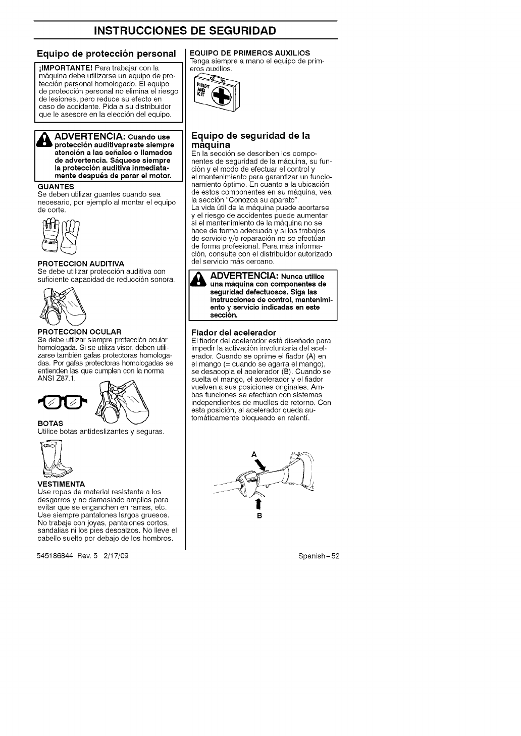
Fiador del acelerador
El fiador del acelerador est& dise_ado para
impedir la activaci6n involuntaria del acel-
erador. Cuando se oprime el fiador (A) en
el mango (= cuando se agarra el mango),
se desacopla el acelerador (B). Cuando se
suelta el mango, el acelerador y el fiador
vuelven a sus posiciones originales. Am-
bas funciones se efectOan con sistemas
independientes de muelles de retorno. Con
esta posici6n, al acelerador queda au-
tom&ticamente bloqueado en ralenti.
A
!
545186844 Rev. 5 2/17/09 Spanish-52
INSTRUCCIONES DE SEGURIDAD
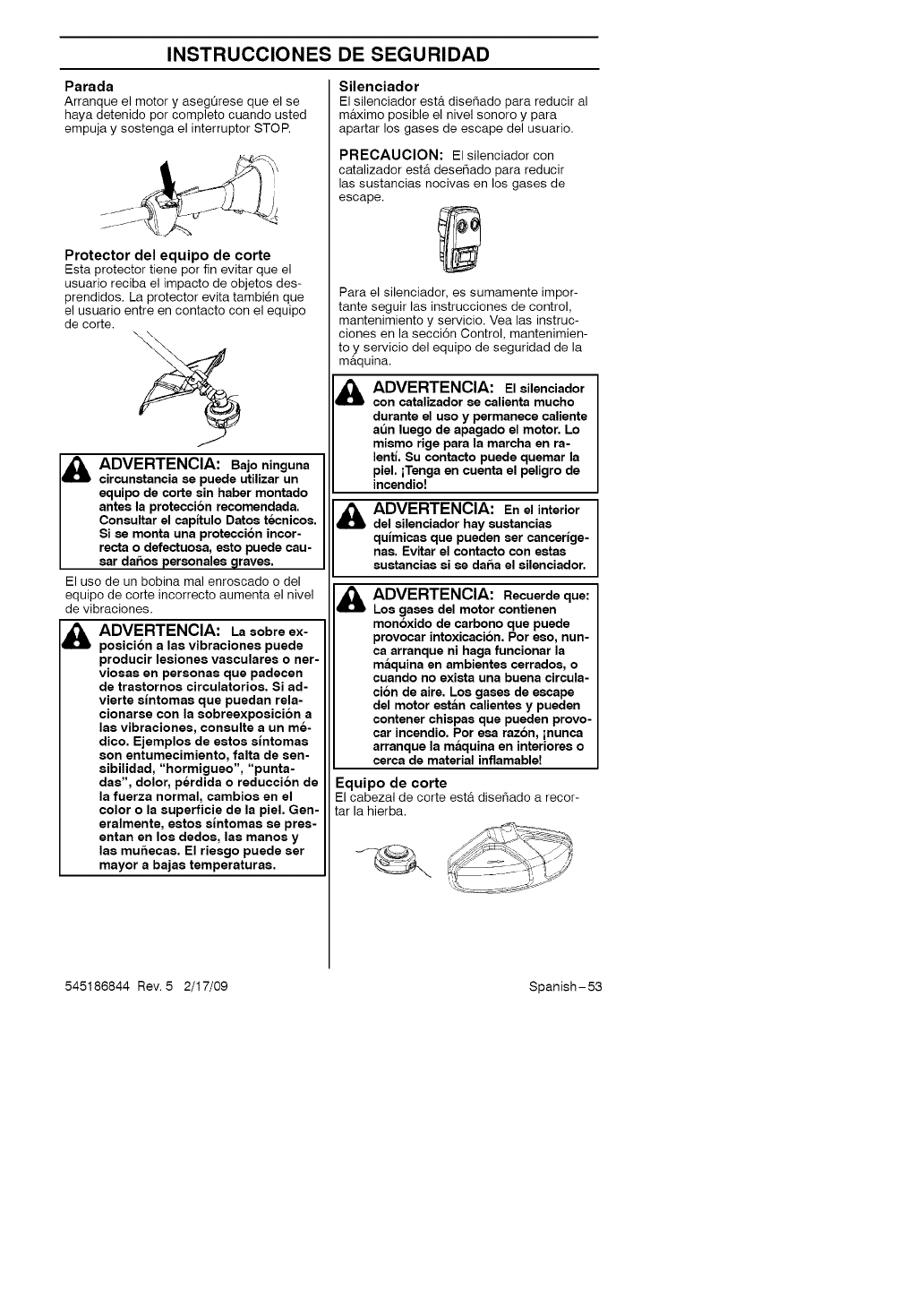
Parada
Arranque el motor y asegQrese que el se
haya detenido por completo cuando usted
empuja y sostenga el interruptor STOR
Protector del equipo de corte
Esta protector tiene por fin evitar que el
usuario reciba el impacto de objetos des-
prendidos. La protector evita tambien que
el usuario entre en contacto con el equipo
de corte.
I& DVERTENCIA: Bajo ninguna
circunatancia ae puede utilizar un
equipo de corte sin haber montado
antes la protecci6n recomendada.
Conaultar el capltulo Datoe tecnicoe.
Si ae monta una protecci6n incor-
recta o defectuoaa, eato puede cau-
aar daftoa peraonalee graves.
El uso de un bobina mal enroscado o del
equipo de corte incorrecto aumenta el nivel
de vibraciones.
ADVERTENCIA: La eobre ex-
poaici6n a laa vibracionea puede
producir leaionea vaecularee o ner-
vioeaa en personae que padecen
de traetornoa circulatorioa. Si ad-
vierte alntomaa que puedan rela-
cionarae con la eobreexpoaici6n a
laa vibracionee, conaulte a un me-
dico. Ejemploa de eetoa alntomaa
son entumecimiento, falta de een-
aibilidad, "hormigueo", "punta-
daa", dolor, perdida o reducci6n de
la fuerza normal, cambioa en el
color o la auperficie de la piel. Gen-
eralmente, eetoa alntomaa ee pree-
entan en los dedoa, laa manoa y
laa mu_ecaa. El rieego puede aer
mayor a bajaa temperaturaa.
Silenciador
El silenciador est& dise_ado para reducir al
m&ximo posible el nivel sonoro y para
apartar los gases de escape del usuario.
PRECAUCION: El silenciador con
catalizador est& dese_ado para reducir
las sustancias nocivas en los gases de
escape.
Para el silenciador, es sumamente impor-
tante seguir las instrucciones de control,
mantenimiento y servicio. Vea las instruc-
ciones en la secci6n Control, mantenimien-
toy servicio del equipo de seguridad de la
maqulna.
ADVERTENCIA: El ailenciador
con catalizador ee calienta mucho
durante el ueo y permanece caliente
at_n luego de apagado el motor. Lo
miamo rige para la marcha en ra-
lenti. Su contacto puede quemar la
piel. iTenga en cuenta el peligro de
incendio!
d_lb ADVERTENCIA: En el interior
del ailenciador hay euatanciaa
qulmicaa que pueden eer cancerlge-
nae. Evitar el contacto con eataa
auatanciaa ai ee dafta el ailenciador.
&ADVERTENCIA: Recuerde que:
Los gases del motor contienen
mon6xido de carbono que puede
provocar intoxicacion. Por eeo, nun-
ca arranque ni haga funcionar la
maquina en ambientee cerradoe, o
cuando no exiata una buena circula-
ci6n de aire. Los gases de escape
del motor eatan calientea y pueden
contener chiapae que pueden provo-
car incendio. Por eea razon, inunca
arranque la maquina en interiorea o
cerca de material inflamable!
Equipo de corte
El cabezal de corte est& disehado a recor-
tar la hierba.
545186844 Rev. 5 2/17/09 Spanish-53

INSTRUCCIONES DE SEGURIDAD
Control, mantenimiento y servi-
cio del equipo del seguridad de
la maquina
IMPORTANTE!
Todos los trabajos de servicio y reparaci6n
de la m&quina requieren una formaci6n es-
)ecial. Esto es especialmente importante
para el equipo de seguridad de
la maquina. Si la m&quina no pasa alguno de
los controles indicados a continuaci6n, acuda
a su taller de servicio local. La compra de
alguno de nuestros productos le garantiza
que puede recibir un mantenimiento y servi-
cio profesional. Si no ha adquirido la mb.qui-
na en una de nuestras tiendas especializa-
das con servicio, solicite informaci6n sobre el
taller de servicio m&s cercano.
Fiador del acelerador
•Compruebe que el acelerador est_ blo-
queado en la posici6n de ralenti cuando
el fiador est& en su posici6n inicial.
Y,
• Apriete el fiador del acelerador y com-
pruebe que vuelva a su posici6n de
partida al soltarlo.
• Compruebe que el acelerador y el fiador
se muevan con facilidad y que funcionen
sus muelles de retorno.
• Consulte las instrucciones bajo el titulo
Arranque. Ponga en marcha la mb.quina y
acelere al m&ximo. Suelte el acelerador y
controle que el equipo de corte se deten-
gay permanezca inm6vil. Si el equipo de
corte gira con el acelerador en ralenti, se
debe controlar la regulaci6n del carbura-
dor para ralenti.
Consulte las instrucciones en la secci6n
"Mantenimiento".
Interruptor de parada
• Arranque el motor y compruebe que se
pare cuando usted empuje y sostenga el
interrupter en la posici6n de parada.
Protector del equipo de corte
Esta protector tiene por fin evitar que el
usuario reciba el impacto de objetos des-
prendidos. La protector evita tambien que
el usuario entre en contacto con el equipo
de corte.
• Controle que la protecci6n no este dana-
day que no tenga grietas.
• Cambie la proteccidn si ha estado ex-
puesta a golpes o si tiene grietas.
• Utilice siempre la protector recomendada
para cada equipo de corte en particular.
Consulte el la secci6n "Datos T_cnicos".
Silenciador
• Nunca utilice una m&quioa que tenga
un silenciador defectuoso.
545186844 Rev. 5 2/17/09 Spanish-54
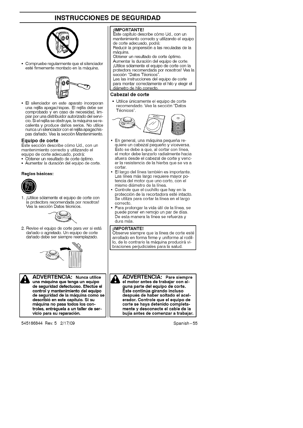
INSTRUCCIONES DE SEGURIDAD
@
• Compruebe regularmente que el silenciador
este firmemente montado en la m_tquina.
• El silenciador en este aparato incorporan
una rejilla apagachispas. El rejilla debe ser
comprobado yen case de necesidad, lim-
piar por una distribuidor autorizado del servi-
cio. Si el rejilla se obstruye, la m_tquina se re-
calienta y produce da6os series. No utilice
nunca un silenciador con el rejilla apagachis-
pas dahado. Vea la secci6n Mantenimiento.
Equipo de corte
Este secci6n describe c6mo Ud., con un
mantenimiento correcto y utilizando el
equipo de corte adecuado, podr_t:
• Obtener un resultado de corte 6ptimo.
• Aumentar la duraci6n del equipo de corte.
Raglas baaicas:
1. iUtilice s61amente el equipo de corte con
la protectors recomendada por nosotros!
Vea la secci6n Dates t_cnicos.
2. Revise el equipo de corte para ver si est&
danado o agrietado. Un equipo de code
danado debe ser siempre reemplazado.
ADVERTENCIA: Nunca utilice
una maquina qua tanga un equipo
de $aguridad defactuoao. Efectt_e el
control y mantenimiento del aquipo
de saguridad de la maquina como se
deecribio en eate capltulo. Si su
maquina no paea todoe los con-
trolaa, entreguela a un taller de aer-
vicio para au raparacion.
ilMPORTANTE!
Este capitulo describe c6mo Ud., con un
mantenimiento correcto y utilizando el equipo
de corte adecuado, podr&:
Reducir la propensi6n alas reculadas de la
m&quina.
Obtener un resultado de corte 6ptimo.
Aumentar la duraci6n del equipo de corte.
iUtilice s61amente el equipo de corte con la
protectors recomendada por nosotres! Vea la
secci6n "Datos T_cnicos".
Lea las instrucciones del equipo de corte
para montar correctamente el hilo y elegir el
di&metro de hilo correcto.
Cabezal de corte
• Utilice Onicamente el equipo de corte
recomendado. Vea la secci6n "Datos
Tecnicos".
• En general, una m&quina pequeSa re-
quiere un cabezal pequeho y viceversa.
Esto se debe a que, al cortar con linea,
el motor debe lanzarlo radialmente hacia
afuera desde el cabezal de corte y venc-
er la resistencia de la hierba que se va a
cortar.
• El largo del linea tambi_n es importante.
Las linea m&s largo requiere mayor po-
tencia del motor que uno corto, con el
mismo di&metro de la linea.
• Controle que el cuchillo que hay en la
protecci6n de la recortadora est_ intacto.
Se utiliza para cortar la linea en el largo
correcto.
• Para prolongar la vida Otil de la linea, se
puede poner en remojo un par de dias.
De esta manera la linea se refuerza y
dura m&s.
ilMPORTANTE!
Observe siempre que la linea de corte est_
arrollado en forma firme y uniforme al rodil-
Io, de Io contrario la m&quina producir& vi-
braciones perjudiciales para la salud.
ADVERTENCIA: Pare aiempre
el motor antes de trabajar con al-
guna parta del equipo de corte.
Eeta continua girando inclueo
daapues de haber soltado el acal-
arador. Controle que el aquipo de
corte ee haya detenido completa-
mente y desconecte el cable de la
bujla antes de comanzar a trabajar.
545186844 Rev. 5 2/17/09 Spanish-55
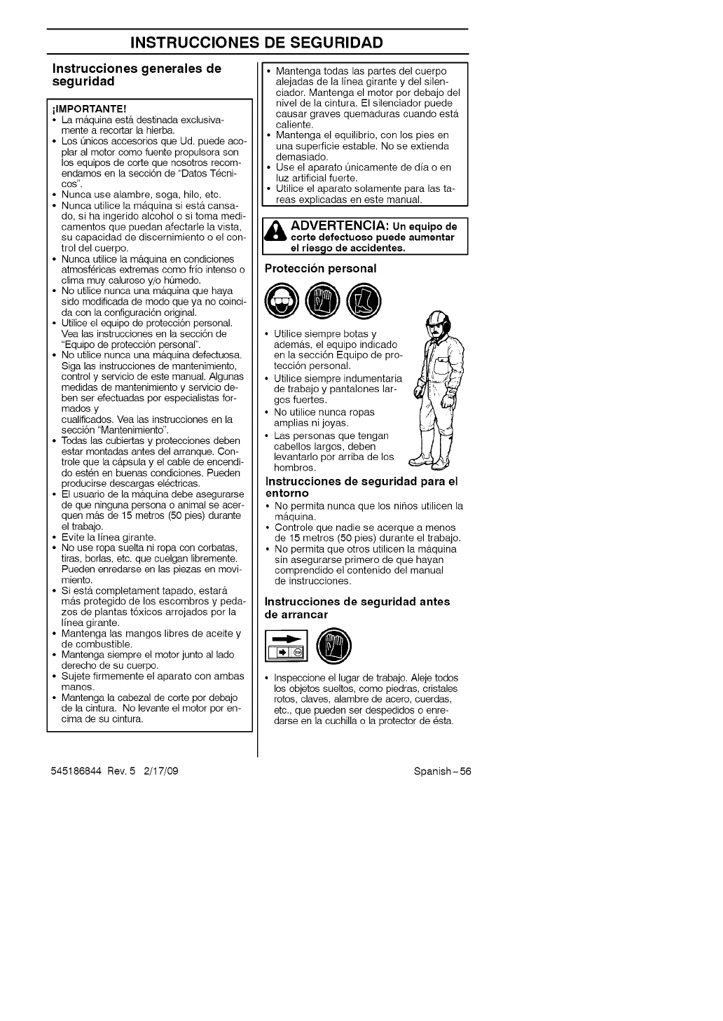
INSTRUCCIONES DE SEGURIDAD
Instrucciones generales de
seguridad
ilMPORTANTE!
• La m_tquina ester destinada exclusiva-
mente a recortar la hierba.
• Los Qnicos accesorios que Ud. puede aco-
plar al motor como fuente propulsora son
los equipos de corte que nosotros recom-
endamos en la secci6n de "Datos T_cni-
OOS".
• Nunca use alambre, soga, hilo, etc.
• Nunca utilice la m&quina si est& cansa-
do, si ha ingerido alcohol o si toma medi-
camentos que puedan afectarle la vista,
su capacidad de discernimiento o el con-
trol del cuerpo.
• Nunca utilice la mb.quina en condiciones
atmosf_ricas extremas como frio intenso o
clima muy caluroso y/o hQmedo.
• No utilice nunca una m&quina que haya
sido modificada de modo que ya no coinci-
da con la configuraci6n original.
• Utilice el equipo de protecci6n personal.
Vea las instrucciones en la secci6n de
"Equipo de protecci6n personal".
• No utilice nunca una m&quina defectuosa.
Siga las instrucciones de mantenimiento,
control y servicio de este manual. Algunas
medidas de mantenimiento y servicio de-
ben ser efectuadas por especialistas for-
mados y
cualificados. Vea las instrucciones en la
secci6n "Mantenimiento".
• Todas las cubiertas y protecciones deben
estar montadas antes del arranque. Con-
trole que la c&psula y el cable de encendi-
do esten en buenas condiciones. Pueden
producirse descargas el_ctricas.
• El usuario de la m&quina debe asegurarse
de que ninguna persona o animal se acer-
quen m&s de 15 metros (50 pies) durante
el trabajo.
• Evite la linea girante.
• No use ropa suelta ni ropa con corbatas,
tiras, borlas, etc. que cuelgan libremente.
Pueden enredarse en las piezas en movi-
miento.
• Si est& completament tapado, estar&
m&s protegido de los escombros y peda-
zos de plantas t6xicos arrojados por la
linea girante.
• Mantenga las mangos libres de aceite y
de combustible.
• Mantenga siempre el motor junto al lado
derecho de su cuerpo.
• Sujete firmemente el aparato con ambas
manos.
• Mantenga la cabezal de corte por debajo
de la cintura. No levante el motor por en-
cima de su cintura.
• Mantenga todas las partes del cuerpo
alejadas de la linea girante y del silen-
ciador. Mantenga el motor por debajo del
nivel de la cintura. El silenciador puede
causar graves quemaduras cuando est&
caliente.
• Mantenga el equilibrio, con los pies en
una superficie estable. No se extienda
demasiado.
• Use el aparato Onicamente de dia o en
luz artificial fuerte.
• Utilice el aparato solamente para las ta-
reas explicadas en este manual.
ADVERTENCIA: Un equipo de ]
corte defectuoso puede aumentar
el riesqo de accidentes.
Proteccion personal
QOO
• Utilice siempre botas y
adem&s, el equipo indicado 'X
en la secci6n Equipo de pro- J
tecci6n personal.
• Utilice siempre indumentaria t
de trabajo y pantalones lar-
gos fuertes.
• No utilice nunca ropas
amplias ni joyas.
• Las personas que tengan
cabellos largos, deben
levantarlo por arriba de los
hombros.
Instrucciones de seguridad para el
entorno
• No permita nunca que los nihos utilicen la
mBquina.
• Controle que nadie se acerque a menos
de 15 metros (50 pies) durante el trabajo.
• No permita que otros utilicen la mBquina
sin asegurarse primero de que hayan
comprendido el contenido del manual
de instrucciones.
Instrucciones de seguridad antes
de arrancar
• Inspeccione el lugar de trabajo. Aleje todos
los objetos sueltos, como piedras, cristales
rotos, claves, alambre de acero, cuerdas,
etc., que pueden ser despedidos o enre-
darse en la cuchilla o la protector de esta.
545186844 Rev. 5 2/17/09 Spanish-56
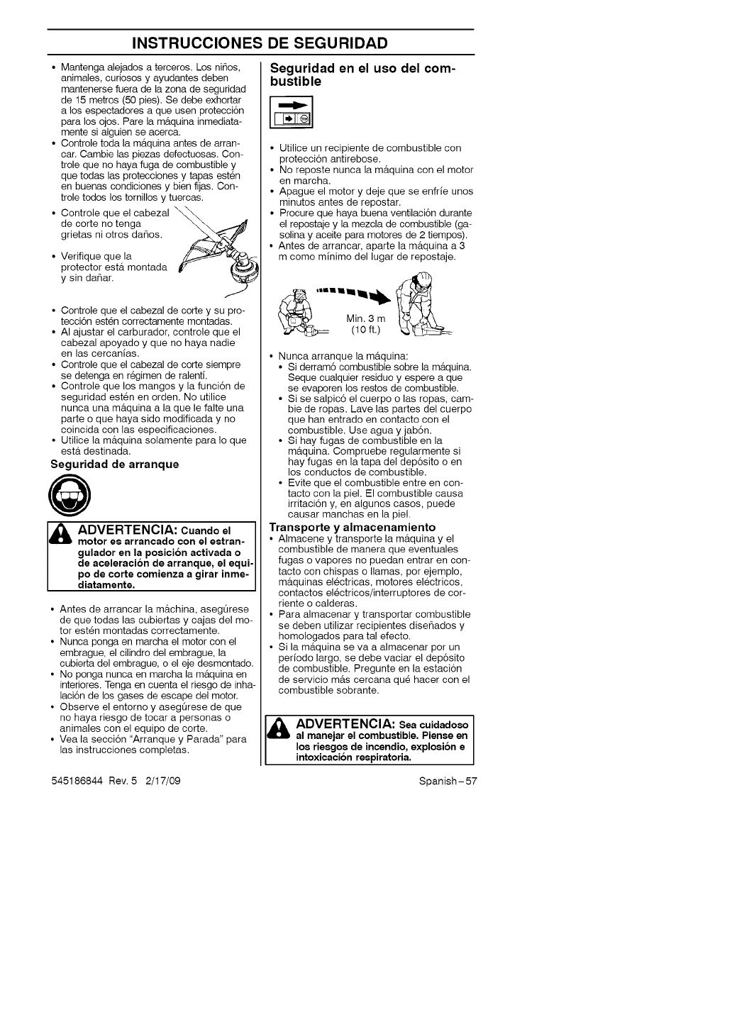
INSTRUCCIONES DE SEGURIDAD
• Mantenga alejados a terceros. Los ni_os,
animales, curiosos y ayudantes deben
mantenerse fuera de la zona de seguridad
de 15 metros (50 pies). Se debe exhortar
a los espectadores a que usen protecci6n
para los ojos. Pare la m&quina inmediata-
mente si alguien se acerca.
• Controle toda la m&quina antes de arran-
car. Cambie las piezas defectuosas. Con-
trole que no haya fuga de combustible y
que todas las protecciones y tapas est_n
en buenas condiciones y bien fijas. Con-
trole todos los tornillos y tuercas.
• Controle que el cabezal \_'_\
de corte no tenga
grietas ni otros da6os.
Verifique que la
protector ester montada
y sin da_ar.
• Controle que el cabezal de corte y su pro-
tecci6n esten correctamente montadas.
• AI ajustar el carburador, controle que el
cabezal apoyado y que no haya nadie
en las cercanias.
• Controle que el cabezal de corte siempre
se detenga en r_gimen de ralenti.
• Controle que los mangos y la funci6n de
seguridad est_n en orden. No utilice
nunca una m_tquina a la que le falte una
parte o que haya sido modificada y no
coincida con las especificaciones.
• Utilice la m_tquina solamente para Io que
ester destinada.
Seguridad de arranque
J& ADVERTENCIA: Cuando el ]
motor es arrancado con el estran- J
gulador en la posici6n activada o J
de aceleracion de arranque, el equi-J
po de corte comienza a girar inme- J
diatamente. J
• Antes de arrancar la m_tchina, asegQrese
de que todas las cubiertas y cajas del mo-
tor est_n montadas correctamente.
• Nunca ponga en marcha el motor con el
embrague, el cilindro del embrague, la
cubierta del embrague, o el eje desmontado.
• No ponga nunca en marcha la m&quina en
interiores. Tenga en cuenta el riesgo de inha-
laci6n de los gases de escape del motor.
• Observe el entorno y aseg0rese de que
no haya riesgo de tocar a personas o
animales con el equipo de corte.
• Vea la secci6n "Arranque y Parada" para
las instrucciones completas.
Seguridad en el use del com-
bustible
• Utilice un recipiente de combustible con
protecci6n antirebose.
• No reposte nunca la m_tquina con el motor
en marcha.
• Apague el motor y deje que se enfrie unos
minutos antes de repostar.
• Procure que haya buena ventilaci6n durante
el repostaje y la mezcla de combustible (ga-
solina y aceite para motores de 2 tiempos).
• Antes de arrancar, aparte la m_quina a 3
m como minimo del lugar de repostaje.
• Nunca arranque la m&quina:
• Si derram6 combustible sobre la m_tquina.
Seque cualquier residue y espere a que
se evaporen los restos de combustible.
• Si se salpic6 el cuerpo o las ropas, cam-
bie de ropas. Lave las partes del cuerpo
que han entrado en contacto con el
combustible. Use agua y jab6n.
• Si hay fugas de combustible en la
m_tquina. Compruebe regularmente si
hay fugas en la tapa del dep6sito o en
los conductos de combustible.
• Evite que el combustible entre en con-
tacto con la piel. El combustible causa
irritaci6n y, en algunos cases, puede
causar manchas en la piel.
Transporte y almacenamiento
• Almacene y transporte la m_tquina y el
combustible de manera que eventuales
fugas o vapores no puedan entrar en con-
tacto con chispas o llamas, por ejemplo,
m_tquinas el_ctricas, motores el_ctricos,
contactos el_ctricos/interruptores de cor-
riente o calderas.
• Para almacenar y transportar combustible
se deben utilizar recipientes dise6ados y
homologados para tal efecto.
• Si la m_tquina se va a almacenar por un
periodo largo, se debe vaciar el dep6sito
de combustible. Pregunte en la estaci6n
de servicio m&s cercana qu_ hacer con el
combustible sobrante.
ADVERTENCIA: Sea cuidadoso
al manejar el combustible. Piense en
los riesgos de incendio, explosion e
intoxicacion respiratoria.
545186844 Rev. 5 2/17/09 Spanish-57
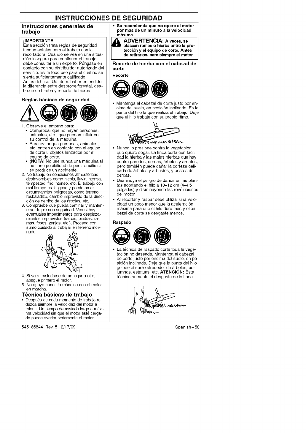
INSTRUCCIONES DE SEGURIDAD
Instrucciones generales de
trabajo
ilMPORTANTE!
Esta secci6n trata reglas de seguridad
fundamentales para el trabajo con la
recortadora. Cuando se yea en una situa-
ci6n insegura para continuar el trabajo,
debe consultar a un experto. P6ngase en
contacto con su distribuidor autorizado del
servicio. Evite todo uso para el cual no se
sienta suficientemente calificado.
Antes del uso, Ud. debe haber entendido
la diferencia entre desbroce forestal, des-
broce de hierba y recorte de hierba.
Reglas basicas de seguridad
1. Observe el entorno para:
• Comprobar que no hayan personas,
animales, etc., que puedan influir en
su control de la m&quina.
• Para evitar que personas, animales,
etc. entren en contacto con el equipo
de corte u objetos lanzados por el
equipo de corte.
•iNOTA! No use nunca una m&quina si
no tiene posibilidad de pedir auxilio si
se produce un accidente.
2. No trabaje en condiciones atmosf_ricas
desfavorables come niebla, Iluvia intensa,
tempestad, frio intenso, etc. El trabajo con
mal tiempo es fatigoso y puede crear
circunstancias peligrosas, como terreno
resbaladizo, cambio imprevisto de la direc-
ci6n de derribo de los _trboles, etc.
3. Compruebe que pueda caminar y manten-
erse de pie con seguridad. Yea si hay
eventuales impedimentos para desplaza-
mientos imprevistos (raices, piedras, ra-
mas, fosos, zanjas, etc.). Proceda con
sumo cuidado al trabe
nado.
ar en terreno incli-
_/_
4. Siva a trasladarse de un lugar a otro,
apague primero el motor.
5. No apoye nunca la m&quina con el motor
en march&
Tecnica basicas de trabajo
• Despu6s de cada momento de trabajo re-
duzca siempre la velocidad del motor a
ralenti. Un tiempo demasiado largo a m_txi-
ma velocidad sin que el motor este carga-
do puede averiar seriamente el motor.
•Se recomienda que no opere el motor
por mas de un minuto a la velocidad
maxima.
ADVERTENCIA: Aveces, se
atascan ramas o hierba entre la pro-
teccion y el equipo de corte. Antes
de retirarlos, pare siempre el motor.
Recorte de hierba con el cabezal de
corte
Recorte
• Mantenga el cabezal de corte justo por en-
cima del suelo, en posici6n inclinada. Es la
punta del hilo la que realiza el trabajo. Deje
que el hilo trabaje con su propio ritmo.
• Nunca Io presione contra la vegetacidn
que quiere segar. La linea corta con facili-
dad la hierba y las malas hierbas que hay
contra paredes, cercas, &rboles y arriates,
pero tambi_n puede da_ar la corteza deli-
cada de &rboles y arbustos, y postes de
cercas.
• Disminuya el peligro de daSos en las plan-
tas acortando el hilo a 10-12 cm (4-4,5
pulgadas) y disminuyendo las revoluciones
del motor.
• AI recortar y raspar debe utilizar una velo-
cidad un poco menor que la aceleraci6n
m_txima para que el hilo dure m&s y el ca-
bezal de corte se desgaste menos.
Raspado
@@@
•La t_cnica de raspado corta toda la vege-
taci6n no deseada. Mantenga el cabezal
de corte justo per encima del suelo, en po-
sici6n inclinada. Deje que la punta del hilo
golpee el suelo alrededor de &rboles, co-
lumnas, estatuas, etc. ATENClON: Esta
tecnica aumenta el desgaste de la line&
545186844 Rev. 5 2/17/09 Spanish-58
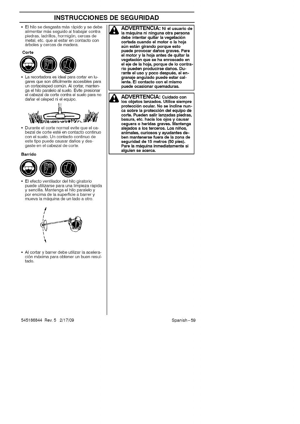
INSTRUCCIONES DE SEGURIDAD
• El hilo se desgasta m_ts r&pido y se debe
alimentar m_ts seguido al trabajar contra
piedras, ladrillos, hormig6n, cercas de
metal, etc. que al estar en contacto con
_trboles y cercas de madera.
Corte
QOO
• La recortadora es ideal para cortar en lu-
gares que son dificilmente accesibles para
un cortac6sped com0n. AI cortar, manten-
ga el hilo paralelo al suelo. Evite presionar
el cabezal de corte contra el suelo para no
dahar el c6sped ni el equipo.
• Durante el corte normal evite que el ca-
bezal de corte est6 en contacto continuo
con el suelo. Un contacto continue de
este tipo puede causar da_os y des-
gaste en el cabezal de corte.
Barrido
QOO
• El efecto ventilador del hilo giratorio
puede utilizarse para una limpieza r_tpida
y sencilla. Mantenga el hilo paralelo y
per encima de la superficie a barrer y
mueva la m_tquina de un lade a otro.
/
/
\
• AI cortar y barrer debe utilizar la acelera-
ci6n m&xima para obtener un buen resul-
tado.
&
&
ADVERTENCIA: Ni el usuario de
la maquina ni ninguna otra persona
debe intentar quitar la vegetaci6n
cortada cuando el motor o la hoja
at_n estan girando porque esto
puede provocar daftos graves. Pare
el motor y la hoja antes de quitar la
vegetaci6n que se ha enroscado en
el eje de la hoja, porque de Io contra-
rio pueden producirse da_os. Du-
rante el uso y poco despues, el en-
granaje angulado puede estar cal-
iente. El contacto con el mismo
puede ocasionar quemaduras.
ADVERTENCIA: Cuidado con
los objetos lanzados. Utilice siempre
protecci6n ocular. No se incline nun-
ca sobre la protecoi6n del equipo de
corte. Pueden salir lanzadas piedras,
basura, etc. hacia los ojos y causar
ceguera o heridas graves. Mantenga
alejados a los terceros. Los nif_os,
animales, curiosos y ayudantes de-
ben mantenerse fuera de la zona de
seguridad de 15 metros (50 pies).
Pare la maquina inmediatamente si
alguien se acerca.
545186844 Rev. 5 2/17/09 Spanish-59
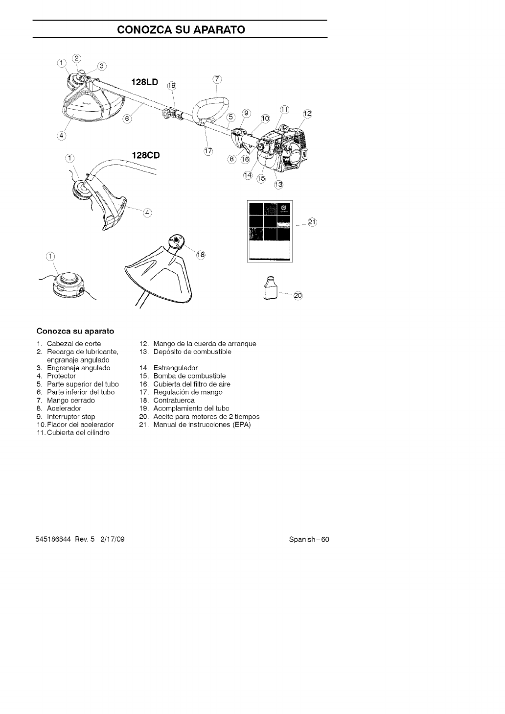
CONOZCA SU APARATO
\,
Conozca su aparato
1. Cabezal de corte
2. Recarga de lubricante,
engranaje angulado
3. Engranaje angulado
4. Protector
5. Parte superior del tubo
6. Parte inferior del tubo
7. Mango cerrado
8. Acelerador
9. Interruptor stop
10. Fiador del acelerador
11. Cubierta del cilindro
12. Mango de la cuerda de arranque
13. Dep6sito de combustible
14. Estrangulador
15. Bomba de combustible
16. Cubierta del filtro de aire
17. Regulaci6n de mango
18. Contratuerca
19. Acomplamiento del tubo
20. Aceite para motores de 2 tiempos
21. Manual de instrucciones (EPA)
545186844 Rev. 5 2/17/09 Spanish-60
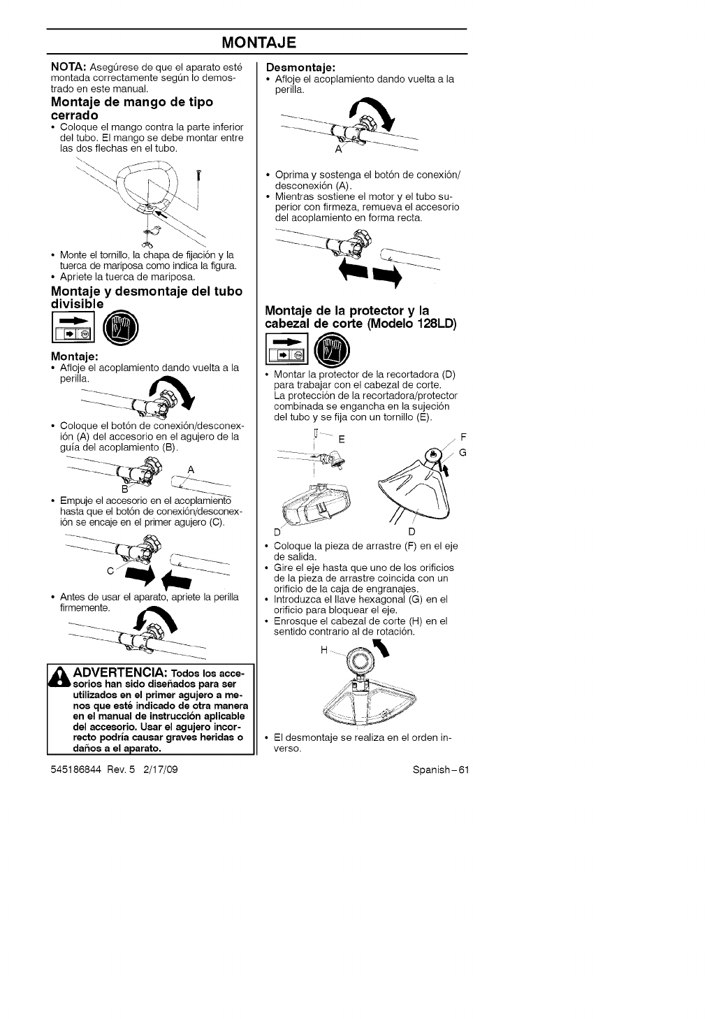
MONTAJE
NOTA: AsegQrese de que el aparato est@
montada correctamente segQn Io demos-
trado en este manual.
Montaje de mango de tipo
cerrado
• Coloque el mango contra la parte inferior
del tubo. El mango se debe montar entre
las dos flechas en el tube.
• Monte el tornillo, la chaps de fijaci6n y la
tuerca de mariposa como indica la figura.
• Apriete la tuerca de mariposa.
Montaje y desmontaje del tubo
divisible
Montaje:
• Afloje el acoplamiento dando vuelta a la
• Ooloque el botdn de conexidn/desconex-
idn (A) del accesorio en el agujero de la
guia del acoplamiento (8).
• Empule el accesorio en el acoplamiento
hasta que el botdn de conexidn/desconex-
idn se enca]e en el primer agujero (C).
• Antes de usar el aparato, apriete la perilla
firmemente.
ADVERTENCIA: Todos los acce-
sorios han sido diseftados pars sar
utilizados an el primer agujaro a me-
nos que este indicado de otra manara
en el manual de instruccion aplicable
dal accesorio. Usar el agujero incor-
recto podrla causar graves haridas o
daftos a el aparato.
Desmontaje:
• Afloje el acoplamiento dando vuelta a la
perilla.
•Oprima y sostenga el bot6n de conexi6n/
desconexi6n (A).
•Mientras sostiene el motor y el tubo su-
perior con firmeza, remueva el accesorio
del acoplamiento en forms recta.
Montaje de la protector y la
cabezal de corte (Modelo 128LD)
• Montar la protector de la recortadora (D)
pars trabajar con el cabezal de corte.
La protecci6n de la recortadora/protector
combinada se engancha en la sujeci6n
del tubo y se fija con un tornillo (E).
I_ " E /F
i
D D
• Coloque la pieza de arrastre (F) en el eje
de salida.
• Gire el eje hasta que uno de los orificios
de la pieza de arrastre coincida con un
orificio de la caja de engranajes.
• Introduzca el Ilave hexagonal (G) en el
orificio pars bloquear el eje.
• Enrosque el cabezal de corte (H) en el
sentido contrario al de rotaci6n.
H
• El desmontaje se realiza en el orden in-
verso.
545186844 Rev. 5 2/17/09 Spanish-61
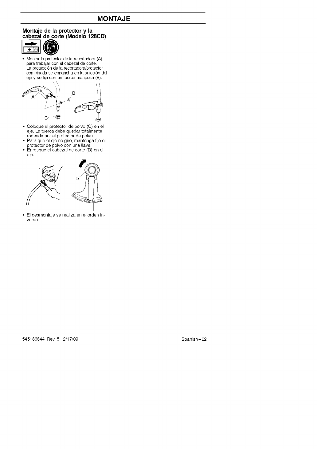
MONTAJE
Montaje de la protector y la
cabezal de corte (Modelo 128CD)
• Nontar la protector de la recortadora (A)
para trabajar con el cabezal de corte.
La proteccidn de la recortadorajprotector
combinada se engancha en la sujeci6n del
eje y se fija con un tuerca mariposa (B).
\ \ _1!
c.....÷ ÷
• Coloque el protector de polvo (C) en el
eje. La tuerca debe quedar totalmente
rodeada per el protector de polvo.
• Para que el eje no gire, mantenga fijo el
protector de polvo con una Ilave.
• Enrosque el cabezal de corte (D) en el
eje.
• El desmontaje se realiza en el orden in-
verso.
545186844 Rev. 5 2/17/09 Spanish-62
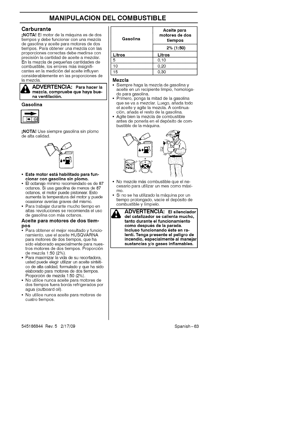
MANIPULACION DEL COMBUSTIBLE
Carburante
iNOTA! El motor de la m_tquina es de dos
tiempos y debe funcionar con una mezcla
de gasolina y aceite para motores de dos
tiempos. Para obtener una mezcla con las
proporciones correctas debe medirse con
precisi6n la cantidad de aceite a mezclar.
En la mezcla de peque_as cantidades de
combustible, los errores m_ts insignifi-
cantes en la medici6n del aceite influyen
considerablemente en las proporciones de
la mezcla.
ADVERTENCIA: Para hacer la
mezcla, compruaba qua haya bue-
na ventilacion.
Gasolina
iNOTA! Use siempre gasolina sin plomo
de alta calidad.
• Este motor esta habilitado para fun-
cionar con gaaolina sin plomo.
• El octanaje minimo recomendado es de 87
octanos. Si usa gasolina de menos de 87
octanos, el motor puede pistonear. Esto
aumenta la temperatura del motor y puede
ocasionar averias graves del mismo.
• Para trabajar durante mucho tiempo en
altas revoluciones se recomienda el uso
de gasolina con m&s octanos.
Aceite para motores de dos tiem-
po8
• Para obtener el mejor resultado y funcio-
namiento, use el aceite HUSQVARNA
para motores de dos tiempos, que ha
sido elaborado especialmente para nues-
tros motores de dos tiempos. Proporci6n
de mezcla 1:50 (2%).
• Para maximizar la vida de su recortadora,
usted puede elegir utilizar un aceite sint_ti-
co de alta calidad, formulado y que ha sido
elaborado para motores de dos tiempos.
Proporci6n de mezcla 1:50 (2%).
• No utilice nunca aceite para motores de
dos tiempos fuera borda refrigerados por
agua (outboard oil).
• No utilice nunca aceite para motores de
cuatro tiempos.
Gasolina
Litroa
5
10
15
Aceite para
motores de dos
tiempoa
2%(1:50)
Litros
0,10
0,20
0,30
Mezcla
• Siempre haga la mezcla de gasolina y
aceite en un recipiente limpio, homologa-
do para gasolina.
• Primero, ponga la mitad de la gasolina
que se va a mezclar. Luego, ahada todo
el aceite y agite la mezcla. A continua-
ci6n, a_ada el resto de la gasolina.
• Agite bien la mezcla de combustible
antes de ponerla en el dep6sito de com-
bustible de la m_tquina.
• No mezcle mb.s combustible que el ne-
cesario para utilizar un mes como m_txi-
mo.
• Si no se ha utilizado la m&quina por un
tiempo prolongado, vacie el dep6sito de
combustible y limpielo.
ADVERTENCIA: El ailenciador I
del catalizador se calienta mucho, I
tanto durante el funcionamiento I
como daspuea de la parada.
Incluao funcionando Kate an ra-
lenti. Tanga presante el paligro de
incandio, aapecialmenta al manejar
auatanc as y/o gases nf amab as.
545186844 Rev. 5 2/17/09 Spanish-63
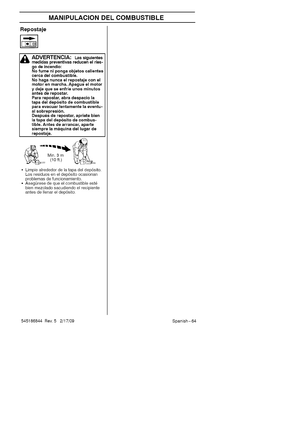
MANIPULACION DEL COMBUSTIBLE
Repostaje
ADVERTENCIA: Lassiguientes
medidas preventivas reducen el ries-
go de incendio"
No fume ni ponga objetos calientes
cerca del combustible.
No haga nunca el repostaje con el
motor en marcha. Apague el motor
y deje que se enfrJe unos minutos
antes de repostar.
Para repostar, abra despacio la
tapa del dep6sito de combustible
para evacuar lentamente la eventu-
al sobrepresion.
Despues de repostar, apriete bien
la tapa del dep6sito de combus-
tible. Antes de arrancar, aparte
siempre la maquina del lugar de
repostaje.
• Limpie alrededor de la tapa del dep6sito.
Los residuos en el dep6sito ocasionan
problemas de funcionamiento.
° AsegOrese de que el combustible este
bien mezclado sacudiendo el recipiente
antes de Ilenar el dep6sito.
545186844 Rev. 5 2/17/09 Spanish-64
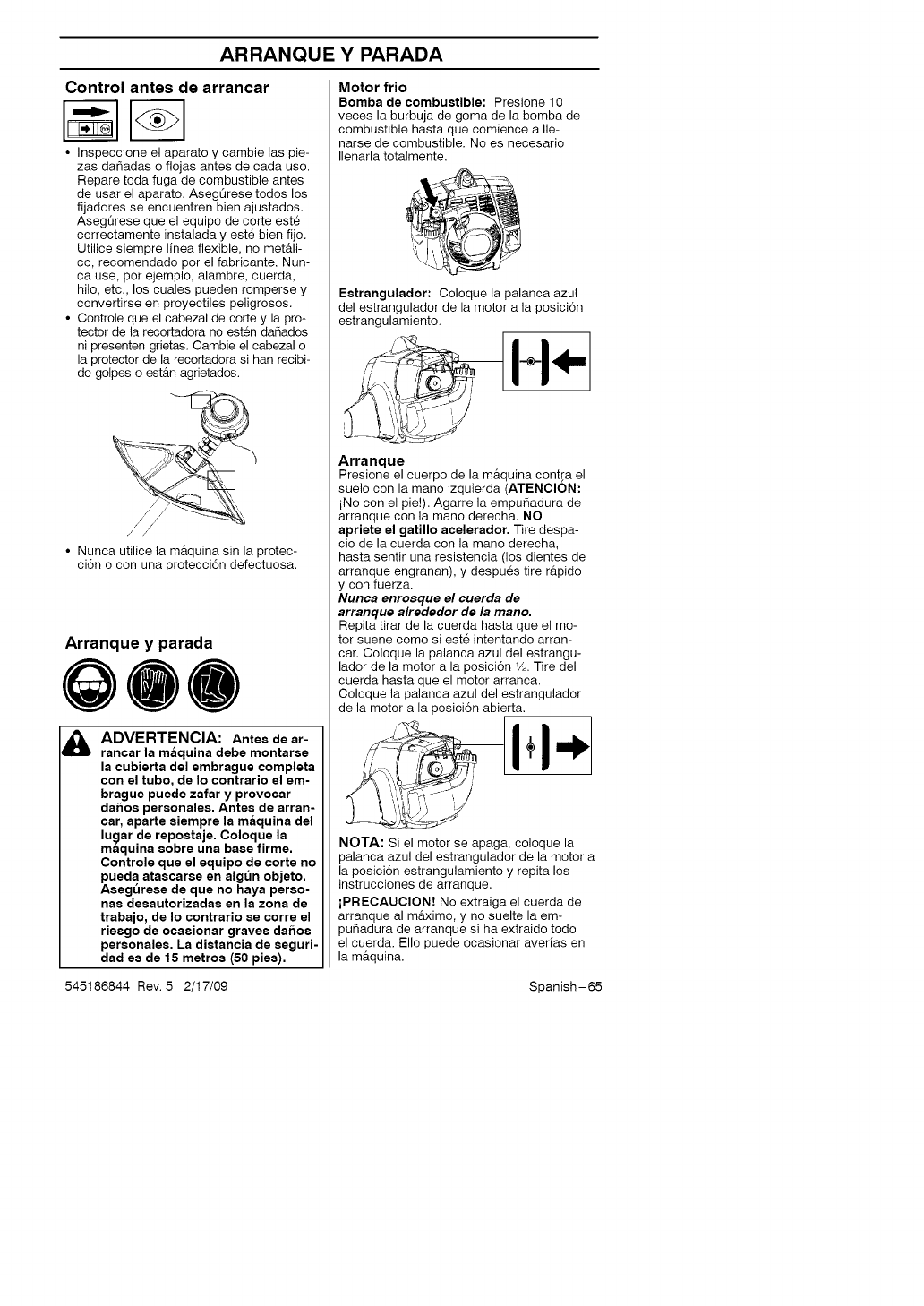
ARRANQUEYPARADA
Control antes de arrancar
• Inspeccione el aparato y cambie las pie-
zas da_adas o flojas antes de cada uso.
Repare toda fuga de combustible antes
de usar el aparato. AsegQrese todos los
fijadores se encuentren bien ajustados.
AsegOrese que el equipo de corte est_
correctamente instalada y est_ bien fijo.
Utilice siempre linea flexible, no met&li-
co, recomendado por el fabricante. Nun-
ca use, por ejemplo, alambre, cuerda,
hilo, etc., los cuales pueden romperse y
convertirse en proyectiles peligrosos.
•Controle que el cabezal de corte y la pro-
tector de la recortadora no est_n da_ados
ni presenten grietas. Cambie el cabezal o
la protector de la recortadora si hart recibi-
do golpes o est_tn agrietados.
q,
\,
• Nunca utilice la m_tquina sin la protec-
oion o con una protecci6n defectuosa.
Arranque y parada
Q@@
ADVERTENCIA: Antes de ar-
rancar la m_lquina daba montarsa
la cubiarta del embrague complata
con el tubo, de Io contrario el em-
brague puede zafar y provocar
dai_oa personalea. Antes de arran-
car, aparte siempra la m_lquina del
lu_lar de repoataje. Coloque la
maqulna sobre una base firme.
Controle que el aquipo de corte no
pueda atascarae en alg_n objeto.
Aseg_reaa de qua no haya perso-
nas desautorizadas en la zona de
trabajo, de Io contrario ae corre el
riaago de ocaaionar graves dal_os
parsonalas. La distancia de aeguri-
dad as de 15 metros (50 pies).
Motor frio
Bomba de combustible: Presione 10
veces la burbuja de goma de la bomba de
combustible hasta que comience a Ile-
narse de combustible. No es necesario
Ilenarla totalmente.
Estrangulador: Coloque la palanca azul
del estrangulador de la motor a la posici6n
estrangulamiento.
/¢_'L /
_,i )
I I'll
I !, '_',tl.,i J
JLC)t¢_ Jy
Arranque
Presione el cuerpo de la m_tquina contra el
suelo con la mano izquierda (ATENClON:
iNo con el pie!). Agarre la empu_adura de
arranque con la mano derecha. NO
apriete el gatillo acelerador, Tire despa-
cio de la cuerda con la mano derecha,
hasta sentir una resistencia (los dientes de
arranque engranan), y despu_s tire r&pido
y con fuerza.
Nunca enrosque el cuerda de
arranque alrededor de la mano.
Repita tirar de la cuerda hasta que el mo-
tor suene como si este intentando arran-
car. Coloque la palanca azul del estrangu-
lador de la motor a la posici6n 1/2.Tire del
cuerda hasta que el motor arranca.
Coloque la palanca azul del estrangulador
de la motor a la posici6n abierta.
NOTA: Si el motor se apaga, coloque la
palanca azul del estrangulador de la motor a
la posici6n estrangulamiento y repita los
instrucciones de arranque.
iPRECAUClON! No extraiga el cuerda de
arranque al m&ximo, y no suelte la em-
punadura de arranque si ha extraido todo
el cuerda. EIIo puede ocasionar averias en
la m&quina.
545186844 Rev. 5 2/17/09 Spanish-65
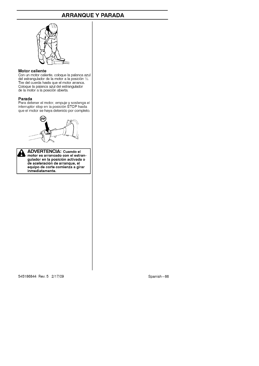
ARRANQUEYPARADA
Motor caliente
Con un motor caliente, coloque la palanca azul
del estrangulador de la motor a la posici6n V,.
Tire del cuerda hasta que el motor arranca.
Coloque la palanca azul del estrangulador
de la motor a la posici6n abierta.
Parada
Para detener el motor, empuje y sostenga el
interruptor stop en la posici6n STOP hasta
que el motor se haya detenido por completo.
I& ADVERTENCIA: Cuando el
motor es arrancado con el estran-
gulador en la posici6n activada o
de aceleraci6n de arranque, el
equipo de corte comienza a girar
inmediatamente.
545186844 Rev. 5 2/17/09 Spanish-66
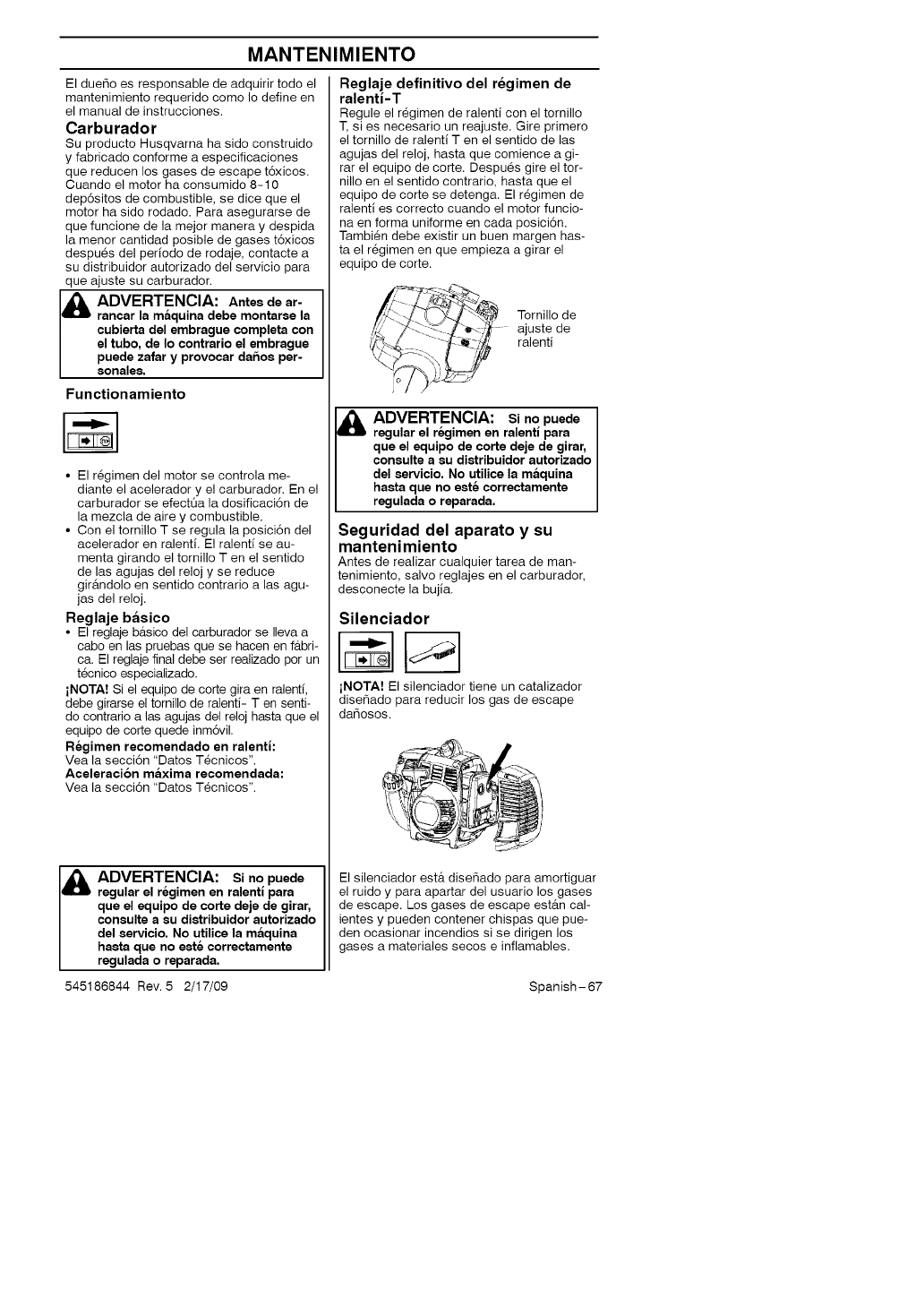
MANTENIMIENTO
El due_o es responsable de adquirir todo el
mantenimiento requerido como Io define en
el manual de instrucciones.
Carburador
Su producto Husqvarna ha sido construido
y fabricado conforme a especificaciones
que reducen los gases de escape t6xicos.
Cuando el motor ha consumido 8-10
dep6sitos de combustible, se dice que el
motor ha sido rodado. Para asegurarse de
que funcione de la mejor manera y despida
la menor cantidad posible de gases t6xicos
despues del periodo de rodaje, contacte a
su distribuidor autorizado del servicio para
que ajuste su carburador.
Id_lb DVERTENCIA: Antes de ar-
rancar la maquina debe montarse la
cubierta del embrague completa con
el tubo, de Io contrario el embrague
puede zafar y provocar daftoa per-
aonaJes.
Functionamiento
°El r_gimen del motor se controla me-
diante el acelerador y el carburador. En el
carburador se efectQa la dosificaci6n de
la mezcla de aire y combustible.
• Con el tornillo T se regula la posici6n del
acelerador en ralenti. El ralenti se au-
menta girando el tornillo Ten el sentido
de las agujas del reloj y se reduce
gir&ndolo en sentido contrario a las agu-
jas del reloj.
Reglaje basico
° El reglaje b_tsico del carburador se Ileva a
cabo en las pruebas que se hacen en f_tbri-
ca. El reglaje final debe ser realizado por un
tecnico especializado.
iNOTA! Si el equipo de corte gira en ralenti,
debe girarse el tornillo de ralenti- Ten senti-
do contrario a las agujas del reloj hasta que el
equipo de corte quede inm6vil.
Regimen recomendado en ralenti:
Vea la secci6n "Datos T_cnicos".
Aceleracion maxima recemendada:
Vea la secci6n "Datos T_cnicos".
I& ADVERTENCIA: si nopuede
regular el regimen en ralentl para
que el equipo de corte deje de girar,
conaulte a su diatribuidor autorizado
del servicio. No utilice la maquina
haata que no este correctamente
regulada o reparada.
545186844 Rev. 5 2/17/09
Reglaje definitivo del regimen de
ralenti-T
Regule el r_gimen de ralenti con el tornillo
T, si es necesario un reajuste. Gire primero
el tornillo de ralenti T en el sentido de las
agujas del reloj, hasta que comience a gi-
rar el equipo de corte. Despu6s gire el tor-
nillo en el sentido contrario, hasta que el
equipo de corte se detenga. El r_gimen de
ralenti es correcto cuando el motor funcio-
na en forma uniforme en cada posici6n.
Tambi_n debe existir un buen margen has-
ta el r_gimen en que empieza a girar el
equipo de corte.
//\. "/" _ Tornillo de
__ ajustede
_ _._/_ ralenti
ADVERTENCIA: Si no puede
regular el regimen en ralentl para
que el equipo de corte deje de girar,
conaulte a su diatribuidor autorizado
del servicio. No utilice la maquina
hasta que no eat_ correctamente
regulada o reparada.
Seguridad del aparato y su
mantenimiento
Antes de realizar cualquier tarea de man-
tenimiento, salvo reglajes en el carburador,
desconecte la bujia.
Silenciador
iNOTA! El silenciador tiene un catalizador
dise6ado para reducir los gas de escape
dahosos.
El silenciador ester dise6ado para amortiguar
el ruido y para apartar del usuario los gases
de escape. Los gases de escape est_tn cal-
ientes y pueden contener chispas que pue-
den ocasionar incendios si se dirigen los
gases a materiales secos e inflamables.
Spanish-67
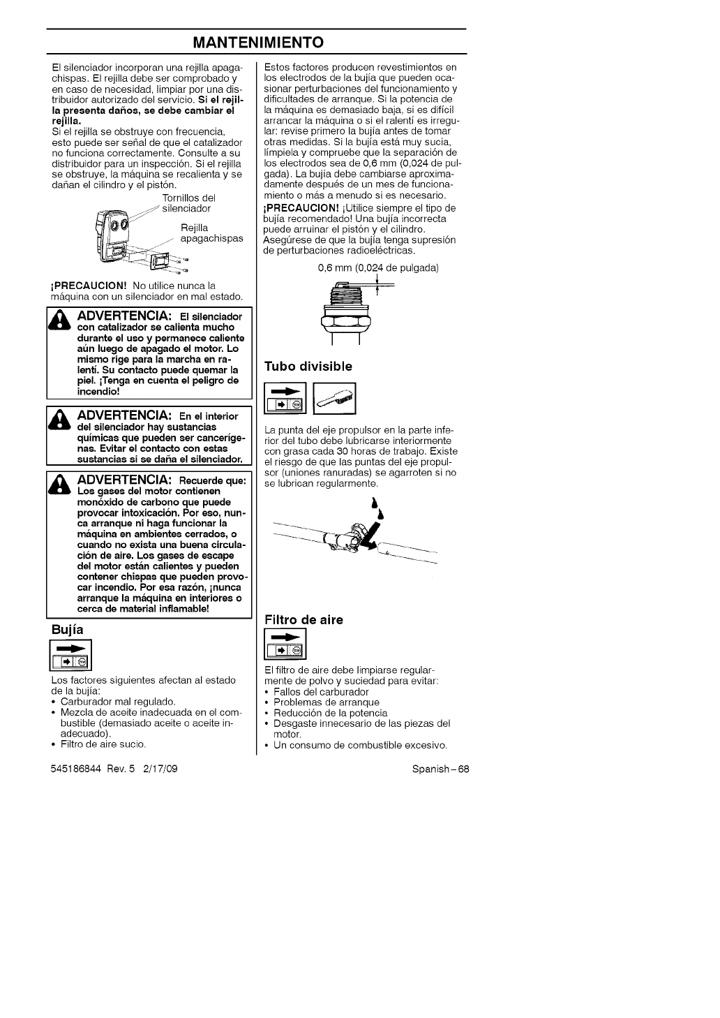
MANTENIMIENTO
El silenciador incorporan una rejilla apaga-
chispas. El rejilla debe ser comprobado y
en caso de necesidad, limpiar por una dis-
tribuidor autorizado del servicio. Si el rejil-
la presenta daftos, se debe cambiar el
rejilla.
Si el rejilla se obstruye con frecuencia,
esto puede ser sepal de que el catalizador
no funciona correctamente. Consulte a su
distribuidor para un inspecci6n. Si el rejilla
se obstruye, la m_quina se recalienta y se
da_an el cilindro y el pist6n.
Tornillos del
_ss silenciador
S_
_iff_ Rejilla
_1_ ......... apagachispas
iPRECAUClON! No utilice nunca la
m&quina con un silenciador en mal estado.
Id_lb DVERTENCIA: El silenciador
con catalizador se calienta mucho
durante el uso y permanece caliente
at_n luego de apagado el motor. Lo
mismo rige para la marcha en ra-
lentl. Su contacto puede quemar la
piel. iTenga en cuenta el peligro de
incendio!
Id_lb DVERTENCIA: En el interior
del silenciador hay sustancias
qulmicas que pueden ser cancerlge-
nas. Evitar el contacto con estas
sustancias si se dafta el silenciador.
ADVERTENCIA: Recuerde que:
Los gases del motor contienen
monoxido de carbono que puede
provocar intoxicaci6n. Por eso, nun-
ca arranque ni haga funcionar la
maquina en ambientes carrados, o
cuando no exista una buena circula-
cion de aire. Los gases de escape
del motor estan calientes y pueden
contener chispas que pueden provo-
car incendio. Por eca razon, inunca
arranque la maquina en interiores o
carca de material inflamable!
Bujia
Los factores siguientes afectan al estado
de la bujia:
• Carburador mal regulado.
• Mezcla de aceite inadecuada en el com-
bustible (demasiado aceite o aceite in-
adecuado).
• Filtro de aire sucio.
Estos factores producen revestimientos en
los electrodos de la bujia que pueden oca-
sionar perturbaciones del funcionamiento y
dificultades de arranque. Si la potencia de
la m_tquina es demasiado baja, si es dificil
arrancar la m&quina o si el ralenti es irregu-
lar: revise primero la bujia antes de tomar
otras medidas. Si la bujia ester muy sucia,
limpiela y compruebe que la separaci6n de
los electrodos sea de 0,6 mm (0,024 de pul-
gada). La bujia debe cambiarse aproxima-
damente despues de un mes de funciona-
miento o m_ts a menudo si es necesario.
iPRECAUCION! iUtilice siempre el tipo de
bujia recomendado! Una bujia incorrecta
puede arruinar el pist6n y el cilindro.
AsegQrese de que la bujia tenga supresi6n
de perturbaciones radioel_ctricas.
0,6 mm (0,024 de pulgada)
Tubo divisible
La punta del eje propulsor en la parte infe-
rior del tubo debe lubricarse interiormente
con grasa cada 30 horas de trabajo. Existe
el riesgo de que las puntas del eje propul-
sor (uniones ranuradas) se agarroten si no
se lubrican regularmente.
Filtro de aire
El filtro de aire debe limpiarse regular-
mente de polvo y suciedad para evitar:
• Fallos del carburador
• Problemas de arranque
• Reducci6n de la potencia
• Desgaste innecesario de las piezas del
motor.
• Un consumo de combustible excesivo.
545186844 Rev. 5 2/17/09 Spanish-68
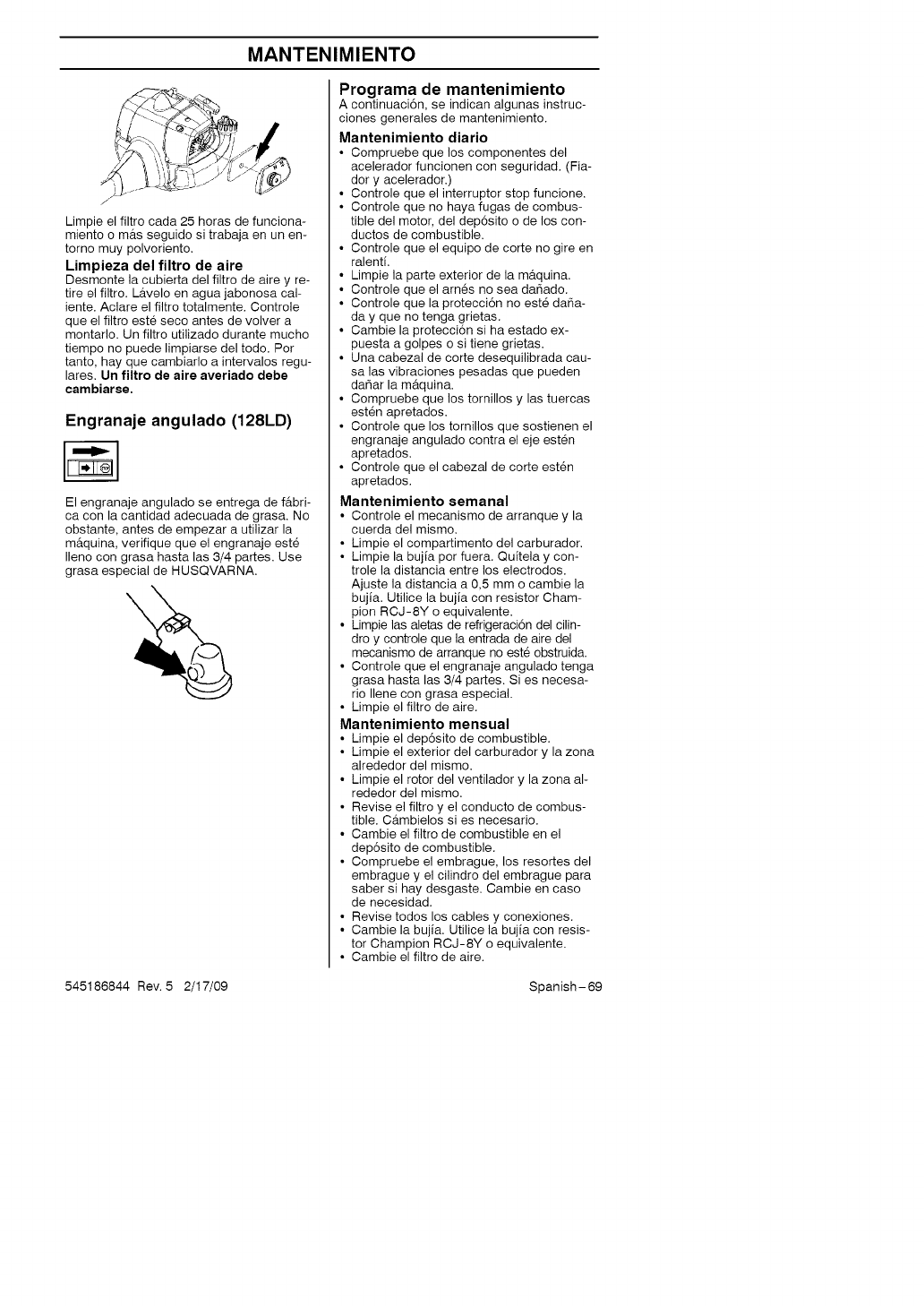
MANTENIMIENTO
i
Limpie el filtro cada 25 horas de funciona-
miento o m_ts seguido si trabaja en un en-
torno muy polvoriento.
Limpieza del filtro de aire
Desmonte la cubierta del filtro de aire y re-
tire el filtro. L_tvelo en agua jabonosa cal-
iente. Aclare el filtro totalmente. Controle
que el filtro este seco antes de volver a
montarlo. Un filtro utilizado durante mucho
tiempo no puede limpiarse del todo. Per
tanto, hay que cambiarlo a iotervalos regu-
lares, Un filtro de aire averiado debe
cambiarse.
Engranaje angulado (128LD)
El engranaje angulado se entrega de f&bri-
ca con la cantidad adecuada de grasa. No
obstante, antes de empezar a utilizar la
m&quina, verifique que el engranaje este
Ileno con grasa hasta las 3/4 partes. Use
grasa especial de HUSQVARNA.
Programa de mantenimiento
A continuaci6n, se indican algunas instruc-
clones generales de mantenimiento.
Mantenimiento diario
• Compruebe que los componentes del
acelerador funcionen con seguridad. (Fia-
dory acelerador.)
• Controle que el interrupter stop funcione.
• Controle que no haya fugas de combus-
tible del motor, del dep6sito o de los con-
ductos de combustible.
• Controle que el equipo de corte no gire en
ralenti.
• Limpie la parte exterior de la m_tquina.
• Controle que el arn_s no sea da_ado.
• Controle que la protecci6n no este da_a-
day que no tenga grietas.
• Cambie la protecci6n si ha estado ex-
puesta a golpes o si tiene grietas.
• Una cabezal de corte desequilibrada cau-
sa las vibraciones pesadas que pueden
dahar la m&quina.
• Compruebe que los tornillos y las tuercas
est_n apretados.
• Controle que los tornillos que sostienen el
engranaje angulado contra el eje esten
apretados.
• Controle que el cabezal de corte esten
apretados.
Mantenimiento semanal
• Controle el mecanismo de arranque y la
cuerda del mismo.
• Limpie el compartimento del carburador.
• Limpie la bujia per fuera. Quitela y con-
trole la distancia entre los electrodes.
Ajuste la distancia a 0,5 mm o cambie la
bujia. Utilice la bujia con resistor Cham-
pion RCJ-8Y o equivalente.
• Limpie las aletas de refrigeraci6n del cilin-
dro y controle que la entrada de aire del
mecanismo de arranque no este obstruida.
• Controle que el engranaje angulado tenga
grasa hasta las 3/4 partes. Si es necesa-
rio Ilene con grasa especial.
• Limpie el filtro de aire.
Mantenimiento mensual
• Limpie el dep6sito de combustible.
• Limpie el exterior del carburador y la zona
alrededor del mismo.
• Limpie el rotor del ventilador y la zona al-
rededor del mismo.
• Revise el filtro y el conducto de combus-
tible. C_tmbielos si es necesario.
• Cambie el filtro de combustible en el
dep6sito de combustible.
• Compruebe el embrague, los resortes del
embrague y el cilindro del embrague para
saber si hay desgaste. Cambie en case
de necesidad.
• Revise todos los cables y conexiones.
• Cambie la bujia. Utilice la bujia con resis-
tor Champion RCJ-8Y o equivalente.
• Cambie el filtro de aire.
545186844 Rev. 5 2/17/09 Spanish-69
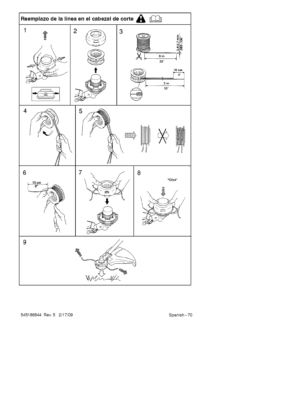
Reemplazo de la linea en el cabezal de corte A
4
3
t
_8
20'
7
"Click"
545186844 Rev. 5 2/17/09 Spanish-70
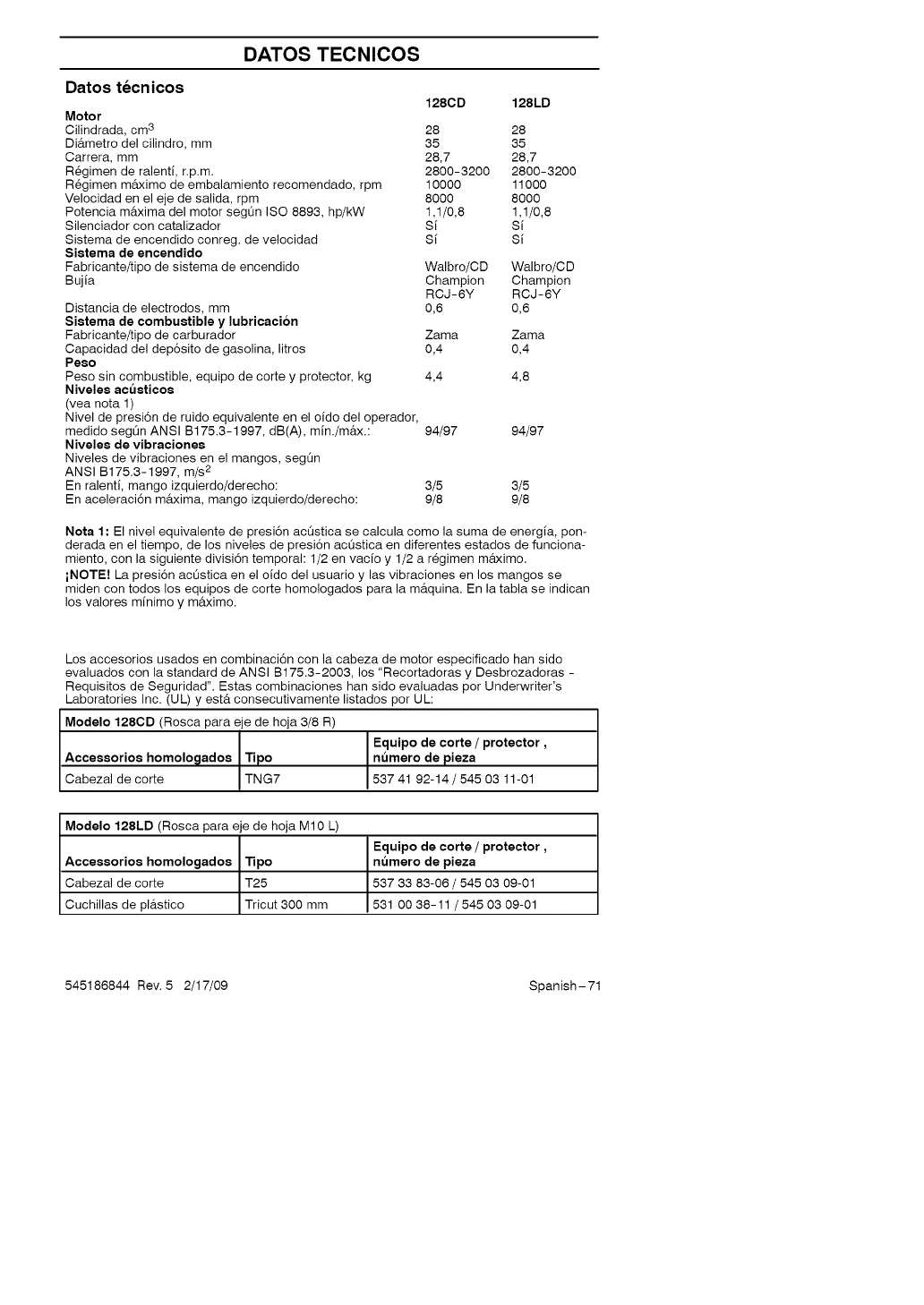
DATOS TECNICOS
Datos tecnicos 128CD 128LD
Motor
Cilindrada, cm 3 28 28
Di_tmetro del cilindro, mm 35 35
Carrera, mm 28,7 28,7
R_gimen de ralenti, r.p.m. 2800-3200 2800-3200
R_gimen m&ximo de embalamiento recomendado, rpm 10000 11000
Velocidad en el eje de salida, rpm 8000 8000
Potencia m&xima del motor segQn ISO 8893, hp/kW 1,1/0,8 1,1/0,8
Silenciador con catalizador Si Si
Sistema de encendido conreg, de velocidad Si Si
Sistema de encendido
Fabricante/tipo de sistema de encendido
Bujia
Distancia de electrodos, mm
Sistema de combustible y lubricaci6n
Fabricante/tipo de carburador Zama Zama
Capacidad del dep6sito de gasolina, litros 0,4 0,4
Peso
Peso sin combustible, equipo de corte y protector, kg 4,4 4,8
Niveles ac_sticos
(vea nota 1)
Nivel de presi6n de ruido equivalente en el oido del operador,
medido segL_n ANSI B175.3-1997, dB(A), min./m&x.: 94/97 94/97
Niveles de vibraciones
Niveles de vibraciones en el mangos, seg_n
ANSI B175.3-1997, m/s 2
En ralenti, mango izquierdo/derecho: 3/5 3/5
En aceleraci6n m&xima, mango izquierdo/derecho: 9/8 9/8
Walbro/CD Walbro/CD
Champion Champion
RCJ-6Y RCJ-6Y
0,6 0,6
Nota 1: El nivel equivalente de presi6n acQstica se calcula como la suma de energia, pon-
derada en el tiempo, de los niveles de presi6n acQstica en diferentes estados de funciona-
miento, con la siguiente divisi6n temporal: 1/2 en vacio y 1/2 a r_gimen mAximo.
iNOTE! La presi6n acQstica en el oido del usuario y las vibraciones en los mangos se
miden con todos los equipos de corte homologados para la m_tquina. En la tabla se indican
los valores minimo y m&ximo.
Los accesorios usados en combinaci6n con la cabeza de motor especificado han sido
evaluados con la standard de ANSI B175.3-2003, los "Recortadoras y Desbrozadoras -
Requisitos de Seguridad". Estas combinaciones han side evaluadas per Underwriter's
Laboratories Inc. (UL) y est& consecutivamente listados per UL:
Modelo 1280D (Rosca para eje de hoja 3/8 R)
Equipo de corte /protector,
Accessorios homolo_ados Tipo nt_mero de pieza
Cabezal de corte TNG7 537 41 92-14 /545 03 11-01
Modelo 128LD (Rosca para eje de hoja M10 L)
Equipo de corte /protector,
Accessorios homologados Tipo nt_mero de pieza
Cabezal de corte T25 537 33 83-06 /545 03 09-01
Cuchillas de pl_tstico Tricut 300 mm 531 00 38-11 /545 03 09-01
545186844 Rev. 5 2/17/09 Spanish-71
DATOS TECNICOS
Los accesorios usados conjuntamente con los cabezas de motor especificados han sido
evaluados a los est&ndares para requisito de seguridad aplicable de la ISO y del EN por
el Instituto Sueco de Pruebas de Maquinaria:
Accessorios N_mero de pieza
Accesorio del cortadora de bordes, con tubo 952 711 607
Accesorio del cultivador, con tubo 952 711 608
Accesorio del soplador, con tubo 952 711 609
Accesorio del cortadora de malezas, con tubo 952 711 610
Accesorio del cortadora de ramas, con tubo 952 711 612
DECLARACION DE GARANTIA
SECCION 1: GARANTIA LIMITADA
Husqvarna garantiza al comprador original
que el producto Husqvarna estar_t libre de
defectos en material y mano de obra desde la
fecha de compra per el "Periodo de Garantia"
del producto como indicamos a continuaci6n:
Garantla de Por Vida: En contra de roturas
en todas las ejes del recortadora, bobinas de
ignici6n y m6dulos.
Garantia de 2 A_os para Equipo NO COM-
ERCIAL: Recortadoras para uso no comer-
cial, no profesional, no institucional y sin fines
de lucro, exceptuando como se especifica en
esta declaraci6n de garantia.
Componentes de sistema de emisi6n de con-
trol necesarios para acatar las regulaciones
de CARB y EPA.
Garantla de 1 A_o: Todas las recortado-
ras para uso comercial, institucional, profe-
sional o con fines de lucro.
SECCION 2: OBLIGACION DE
HUSQVARNA BAJO GARANTIA
Husqvarna reparar_t o reemplazar& elemen-
tos defectuosos sin cargo alguno por pie-
zas o labor si el elemento fallara debido a
defectos de material o mano de obra du-
rante el periodo de garantia.
SECCION 3: ARTICULOS NO CU-
BIERTOS BAJO ESTA GARANTIA
Los siguientes articulos no est_tn cubiertos
bajo esta garantia:
(1) Articulos de mantenimiento normal por
parte del cliente que se vayan gastando
por el uso normal y regular, incluyendo,
pero no limitandose alas filtros, lubri-
cantes, resortes para rebobinar, bujias, y
cuerdas de arranque.
(2) Descoloramiento natural del material de-
bido a rayos ultravioleta.
SECCION 4: EXCEPCIONES Y LIMI-
TACIONES
La garantia no aplicar& a defectos que re-
sulten de Io siguiente:
(1) Accidentes, abuso, mal uso, negligencia
y descuido, incluyendo el uso de com-
bustible rancio, suciedad, abrasivos, hu-
medad, enmohecimiento, corrosi6n o cu-
alquier reacci6n adversa debido al alma-
cenaje o h&bitos de uso incorrectos.
(2) La negligencia al operar o mantener el
aparato de acuerdo con el Manual del
Usuario/Propietario o la hoja de instruc-
ciones provista por Husqvarna.
(3) I_as alteraciones o modificaciones que
cambien la intenci6n de uso del producto
o que afecte el funcionamiento del pro-
ducto, su operaci6n, seguridad, o durabili-
dad o que cause que el producto no
cumpla con las leyes aplicables.
(4) Da_os adicionales alas piezas o elemen-
tos debido al uso continuo que ocurra
despues de Io antes mencionado.
I_AS REPARACIONES O EL REEMPLAZO
COMO SE PROVEE BAJO ESTA GARANTIA
SON RESPONSABILIDAD EXCLUSIVA DEL
COMPRADOR, HUSQVARNA NO DEBERA
SER RESPONSABLE POR NINGUN DANO
INCIDENTAL O A CONSECUENCIA DEL IN-
CUMPLIMIENTO DE CUALQUIER GARAN-
TIA EXPRESA O INDICADA EN ESTOS
PRODUCTOS EXCEPTO AL GRADO QUE
LA LEY APLICABLE PROHIBE. CUALQUIER
GARANTIA INDICADA O MERCADEO O
PROPIEDAD DE ESTOS PRODUCTOS
PAPA UN PROPOSlTO EN PARTICULAR
ESTA LIMITADO A LA DUPACION DEL PER-
IODO DE GARANTIA COMO SE DEFINE EN
LA DECLARACION DE GARANTIA LIMITA-
DA. HUSQVARNA SE RESERVA EL DERE-
CHO A CAMBtAR O MEJOPAR EL DISEI_JO
DEL PRODUCTO SIN PREVlO AVISO, Y NO
ASUME NINGUN TIPO DE RESPONSABILI-
DAD PARA ACTUALIZAR PRODUCTOS QUE
HAN SIDO MANUFACTURADOS PREVlA-
MENTE.
545186844 Rev. 5 2/17/09 Spanish-72
DECLARACION DE GARANTIA
Algunos estados no permiten exclusiones de
da_os incidentales o consecuentes o limita-
clones en cuanto al periodo de duraci6n de
una garantia, Io que implica que Io menciona-
do anteriormente puede que no posea ningOn
tipo de validez en el estado en donde usted
reside. Esta garantia le provee a usted dere-
chos legales especificos, y puede que usted
cuente con otros derechos los cuales varian
entre diferentes estados.
SECCION 5: RESPONSABILIDAD
DEL CLIENTE
A este producto se le debe aplicar el cuidado,
mantenimiento, uso, almacenaje y mantenimi-
ento general razonables como se especifica
en la secci6n de mantenimiento del manual
del Usuario/Propietario. Si ocurriera un pro-
blema en la operaci6n o algQn fallo, este pro-
ducto no deber_ ser utilizado y deber_ ser
entregado de inmediato a un agente Husqvar-
na para su evaluaci6n. La prueba de compra,
como se explica en la secci6n 6, es respon-
sabilidad completa del cliente.
SECCION 6: PROCEDIMIENTO
PARA OBTENER CONSIDERACION
DE GARANTIA
Es responsabilidad del propietario y del
agente el asegurarse de que la tarjeta de
registro de garantia sea completada de for-
ma apropiada y enviada a la Compa_ia
Husqvarna. Esta tarjeta deber& ser enviada
por correo dentro de los diez (10) contados
despu_s de la fecha de compra, con el
prop6sito de poder confirmar la garantia y
facilitar el servicio de post venta. Para ob-
tener servicio de garantia de parte de un
agente Husqvarna autorizado se deber_t
presentar prueba de compra.
Esta prueba deber& incluir la fecha de com-
pra, nQmero de modelo, nQmero de serie y
el nombre y direcci6n completos del agente
que vendi6 el producto. Para obtener el
beneficio de esta garantia, el producto que
se piensa se encuentra defectuoso deber&
ser entregado a tiempo a un agente Husq-
varna, a no m&s tardar de los treinta (30)
dias despu_s de haber surgido el problema
de operaci6n o el fallo del producto.
El producto deber& ser enviado a costo del
cliente. Los cargos por recogido y entrega
no est_tn cubiertos bajo esta garantia. Un
agente autorizado Husqvarna puede ser
Iocalizado normalmente en las p&ginas
amarillas de su directorio de tel_fonos local
o Ilamando al 1-800-438-7297.
6Husqvarna
7349 Statesville Road
CHARLOTTE, NC 28269
DECLARACION DE GARANTIA DE CONTROL
DE EMISION DE U.S. EPA/CALIFORNIA/
AGENCIA AMBIENTAL CANADIENSE
SUS DERECHOS Y OBLIGACIONES
DE GARANTIA:
La Agencia de Protecci6n Ambiental de los
Estados Unidos, la Junta de Recursos Ambi-
entales de California, la Agencia Ambiental
Canadiense y HUSQVARNA se complacen
en explicar la garantia con la que cuenta el
sistema de control de emisi6n en su motor
peque_o, modelo 2009 y m_ts adelante, para
uso fuera de carretera. En California, todos
los motores peque_os para uso fuera de car-
retera deben ser dise_ados, construidos y
equipados para satisfacer las rigurosas nor-
mas antihumo que posee el estado.
HUSQVARNA deber_t garantizar el sistema
de control de emisi6n en su m_tquina de mo-
tor pequeSo para uso fuera de carretera por
los periodos de tiempo que explicamos a
continuaci6n y con la condici6n de que su
m&quina de motor pequeSo para uso fuera de
carretera no haya sufrido ningQn tipo de abu-
so, negligencia o mantenimiento inapropiado.
Su sistema de control de emisi6n incluye pie-
zas tales como el carburador, el sistema de
ignici6n y el tanque de combustible. Donde
exista una condici6n que requiera reparaci6n
bajo garantia, HUSQVARNA reparar& gratis
su motor peque_o para uso fuera de carret-
era. Los gatos cubiertos bajo la garantia in-
cluyen el diagn6stico, las piezas y labor.
CUBIERTA DE GARANTIA DEL FAB-
RICANTE:
Si cualquier pieza relacionada con el sistema
de emisi6n de su motor (como hemos enum-
erado en la lista de piezas de control de emi-
si6n bajo garantia) se encontrara defectuosa
o defectos en el material o en la labor del mo-
tor causaran que tal pieza comenzara a fallar,
la pieza ser& reparada o reemplazada por
HUSQVARNA.
545186844 Rev. 5 2/17/09 Spanish-73
DECLARACION DE GARANTIA DE CONTROL
DE EMISION DE U.S. EPA/CALIFORNIA/
AGENCIA AMBIENTAL CANADIENSE
GARANTIA DE RESPONSABILIDAD
DE DEL DUENO:
Como dueffo de una m_tquina de motor pe-
queffo para uso fuera de carretera, usted
ser_t responsable por el mantenimiento ade-
cuado en los periodos previamente progra-
mados y enumerados en su manual de
instrucciones. HUSQVARNA recomienda
que guarde todos los recibos que indiquen
que se ha desempefiado mantenimiento en
su m_tquina de motor pequefio para uso
fuera de carretera, pero HUSQVARNA no
podr& negar el servicio bajo garantia Qnica-
mente a causa de la falta de recibos o por
el incumplimiento de su parte en asegu-
rarse que el mantenimiento programado
haya sido desempefiado. Como dueffo de
una m&quina de motor pequeffo para uso
fuera de carretera, usted deber& contar con
el conocimiento de que HUSQVARNA
puede negar la cubierta bajo garantia si su
m_tquina de motor pequefio para uso fuera
de carretera o alguna pieza de la misma ha
dejado de funcionar debido al abuso, negli-
gencia, mantenimiento inapropiado, modifi-
caciones no aprobadas o el uso de piezas
que no hayan sido fabricadas o aprobadas
por el fabricante original del equipo. Es re-
sponsabilidad suya el Ilevar su m_tquina de
motor pequefio para uso fuera de carretera a
un centro de reparaci6n autorizado HUSQ-
VARNA tan pronto como se presente el pro-
blema. Las reparaciones bajo garantia deb-
er_tn ser completadas en un periodo de tiem-
po razonable, que no exceda los 30 dias. Si
cuenta usted con alguna pregunta en relaci6n
a sus derechos y responsabilidades de ga-
rantia, usted deber_t comunicarse con su cen-
tro de servicio autorizado m&s cercano, Ilamar
a HUSQVARNA al 1-800-487-5951, o visite
www.usa.husqvarna.com.
FECHA DEL COMIENZA DE LA
GARANTIA:
El periodo de garantia comienza en la fecha
de compra de la m_tquina de motor pequeffo
para uso fuera de carretera.
DURACION DE LA GARANTIA:
Esta garantia cuenta con un periodo de dura-
ci6n de dos afios comenzando en la fecha
inicial de compra.
QUE CUBRE LA GARANTIA: REPA-
RACION O REEMPLAZO DE PIEZAS.
La reparaci6n o el reemplazo de cualquier
pieza garantizada ser&n desempeffados y
ofrecidos al duefio sin costo alguno en un
centro de servicio HUSQVARNA. Si cuenta
usted con alguna pregunta en relaci6n a sus
derechos y responsabilidades de garantia,
usted deber& comunicarse con su centro de
servicio autorizado m&s cercano, Ilamar a
HUSQVARNA al 1-800-487-5951, o visite
www.usa.husqvama.com.
PERIODO DE GARANTIA:
Cualquier pieza garantizada que no est_ pro-
gramada para ser reemplazada como parte
del mantenimiento requerido, o que este pro-
gramada Qnicamente para inspecci6n regular
para efectos de "reparaci6n o reemplazo si
fuera necesario" deber_t garantizarse por un
periodo de dos afros. Cualquier pieza garan-
tizada que est_ programada para ser reem-
plazada como parte del mantenimiento re-
querido deber& estar garantizada por el perio-
do de tiempo que comienza en la fecha de
compra inicial hasta la fecha del primer reem-
plazo programado para dicha pieza.
DIAGNOSTICO:
No se deber_t cobrar al duefio ningt_n tipo de
cargos por la labor de diagn6stico la cual de-
termine que una pieza garantizada se en-
cuentra defectuosa si el trabajo de diagn6sti-
co ha sido desempefiado por un centro de
servicio autorizado HUSQVARNA.
DANOS POR CONSECUECIA:
HUSQVARNA podr_t ser responsable de
daffos ocurridos a otras piezas del motor cau-
sados per la falla de una pieza garantizada
que se encuentre bajo el periodo de garantia.
QUE NO CUBRE LA GARANTIA:
Todas las fallas causadas por el abuso, ne-
gligencia o mantenimiento inapropiado no
est_tn cubiertas.
PIEZAS AI_ADIDAS O MODIFICA-
DAS:
El uso de piezas afiadidas o la modificaci6n
de piezas podr&n servir como base para que
se anule la reclamaci6n de garantia. La ga-
rantia de HUSQVARNA no se responsabiliza
por el mal funcionamiento debido al uso de
piezas affadidas o de piezas modificadas.
COMO ENTABLAR UNA RECLAMA-
CION:
Si cuenta usted con alguna pregunta relacio-
nada con sus derechos y responsabilidades
de garantia, usted deber& entrar en contacto
con su centro de servicio autorizado
HUSQVARNA m&s cercano, Ilamar a
HUSQVARNA al 1-800-487-5951, o visite
www.usa.husqvama.com.
DONDE OBTENER SERVIClO DE
GARANTIA:
Servicio o reparaciones bajo garantia deb-
er&n ser provistas en todos los centros de
servicio HUSQVARNA. Por favor comun-
iquese al 1-800-487-5951 o visite www.
usa.husqvama.com.
545186844 Rev. 5 2/17/09 Spanish-74
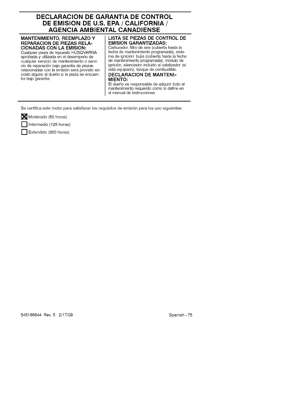
DECLARACION DE GARANTIA DE CONTROL
DE EMISION DE U.S. EPA/CALIFORNIA/
AGENCIA AMBIENTAL CANADIENSE
MANTENIMIENTO, REEMPLAZO Y
REPARACION DE PIEZAS RELA-
CIONADAS CON LA EMISION:
Cualquier pieza de repuesto HUSQVARNA
aprobada y utilizada en el desempe_o de
cualquier servicio de mantenimiento o servi-
cio de reparaci6n bajo garantia de piezas
relacionadas con la emisi6n ser_t provisto sin
costo alguno al dueho si la pieza se encuen-
tra bajo garantia.
LISTA SE PIEZAS DE CONTROL DE
EMISION GARANTIZADAS:
Carburador, filtro de aire (cubierta hasta la
fecha de mantenimiento programada), siste-
ma de ignici6n: bujia (cubierta hasta la fecha
de mantenimiento programada), m6dulo de
ignici6n, silenciador incluido al catalizador (si
est& equipado), tanque de combustible.
DECLARACION DE MANTENI-
MIENTO:
El due_o es responsable de adquirir todo el
mantenimiento requerido como Io define en
el manual de instrucciones.
Se certifica este motor para satisfacer los requisitos de emisi6n para los uso siguientes:
[] Moderado (50 horas)
[] Intermedio (125 horas)
[] Extendido (300 horas)
545186844 Rev. 5 2/17/09 Spanish-75

545186844 Rev. 5 2/17/09 BRW
usqvarna
www.husqvarna.com
