Husqvarna 322L User Manual WEEDTRIMMER Manuals And Guides L0401330
HUSQVARNA Line Trimmers/Weedwackers, Gas Manual L0401330 HUSQVARNA Line Trimmers/Weedwackers, Gas Owner's Manual, HUSQVARNA Line Trimmers/Weedwackers, Gas installation guides
User Manual: Husqvarna 322L 322L HUSQVARNA WEEDTRIMMER - Manuals and Guides View the owners manual for your HUSQVARNA WEEDTRIMMER #322L. Home:Lawn & Garden Parts:Husqvarna Parts:Husqvarna WEEDTRIMMER Manual
Open the PDF directly: View PDF ![]() .
.
Page Count: 36

Operator's manual (EPA II) _ _
322L 12EIL 325C 325Cx.sER,ES
5Lx.sER,ES25LxT.SER,ES 25LDx.sER,ES
Please read these instructions carefully and make
sure you understand them before using the machine. English

SYMBOL EXPLANATION
Symbols
WARNING! Clearing saws,
brushcutters and trimmers can be
dangerous[
Careless or incorrect use can result in
serious or fatal injury to the operator or
others.
Read through the Operator's Manual
carefully and understand tile content
before using the machine.
@Always use
•Aprotective helmet where there is a
risk of falling objects
• Ear protection
• Approved eye protection
max
0000 rpm Max. speed of output axle, rpm
This product is in accordance with
applicable CE directives.
Beware of thrown objects and
ricochets.
The operator of the machine shall
ensure, while working, that no persons
or animals come closer than 15 metres.
Blade can thrust violently when
coming in contact with any object.
Blade thrust can cause amputation of
arms or legs. Keep people and animals
50 feet away. Never use blades unless
re.commended handlebar, shoulder
strap, attaching hardware and blade
deflector are installed.
Arrows which show limits for handle
mounting.
m
m
_,,,_ ¢ ,% _,,_
Always wear approved protective gloves.
Use anti-slip and stable boots.
Only use nor>metallic, flexible cutting
elements, that is trimmer head with
trimmer cord.
Only intended for the trimmer head.
Other symbols/decals on the machine refer to
special certification requirements for certain
markets.
Checks and/or maintenance should be
carried out with the engirm switched off,
with the stop switch in the STOP
position.
Always wear approved protective gloves.
Regular cleaning required.
Ocular control.
I¢1_ I Approved eye protection must always be
used.
2- English
CONTENTS
Husqvarna AB has a policy of continuous product development
and therefore reserves the right to modify the design and
appearance of products without prior notice.
Maintenance, replacement, or repair of the emission control
devices and systems may be performed by any nonroad
engine repair establishment or individual.
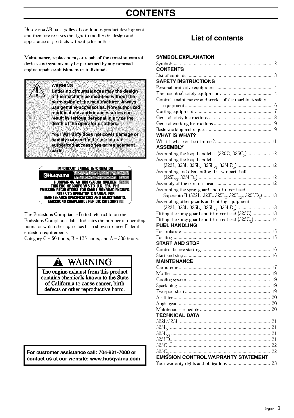
SIMPORTANTENGINEINFORMATION
HUSQVARNAAB HUSI(VARRASWEDEN _
THISENGINECONFORMSTO U.S. EPA PH2
EMISSIONREGULATIONSFORSMALLNONROADENGINES.
REFERTO OPERATOR'SMANUALFOR
MAINTENANCESPECIFICATIONSANDADJUS'IMENTS.
\EMISSIONSCOMPLIANCEPERIOD:CA'IEGORY_ /
The Emissions Compliance Period referred to on the
Emissions Compliance label indicates the rmmber of operating
hours for which the engine has been shown to meet Federal
emission requirements.
Category C = 50 hours, B = 125 hours, and A = 300 hours.
WARNING
The engine exhaust from this product
contains chemicals known to the State
of California to cause cancer, birth
defects or other reproductive harm.
I For customer assistance call: 704-921-7000 or I
contact us at our website: www.husqvarna.com I
I
List of contents
SYMBOL EXPLANATION
Symbols ............................................................................... 2
CONTENTS
List of contents .................................................................... 3
SAFETY INSTRUCTIONS
Personal protective equipment ............................................. 4
The machine's safety equipment .......................................... 4
Control, maintermnce and service of the machine's safety
equipment ...................................................................... 6
Cutting equipment .............................................................. 7
General safety instructions ................................................... 8
General working instructions ............................................... 9
Basic working techniques ..................................................... 9
WHAT IS WHAT?
What is what on the trimmer? ............................................ 11
ASSEMBLY
Assembling the loop handlebar (325C, 325Cx) .................. 12
Assembling the loop handlebar
(322L, 323L, 325L x, 325Lxv 325LDx) .......................... 12
Assembling and dismantling the two-part shaft
(325Lv_, 325LDx) ......................................................... 12
Assembly of the trimmer head ........................................... 12
Assembling the spray guard and trimmer head
Superauto II (322L, 323L, 325L x, 325Lx_, 325LDx) ..... 13
Assembling other guards and cutting equipment
(322L, 323L, 325L x, 325Lv_, 325LDx) .......................... 13
Fitting the spray guard and trimmer head (325C) .............. 13
Fitting the spray guard and trimmer head (325Cx) ............ 14
FUEL HANDLING
Fuel mixture ...................................................................... 15
Fuelling .............................................................................. 15
START AND STOP
Control before starting ....................................................... 16
Start and stop ..................................................................... 16
MAINTENANCE
Carburetor ......................................................................... 17
Muffler .............................................................................. 19
Cooling system .................................................................. 19
Spark plug .......................................................................... 19
Two-part shaft .................................................................... 19
Air filter ............................................................................. 20
Angle gear .......................................................................... 20
Maintenance schedule ........................................................ 20
TECHNICAL DATA
322L/323L ........................................................................ 21
325L x ................................................................................ 21
325Lx, I................................................................................ 21
325LD x.............................................................................. 21
325C ................................................................................. 22
325C x ................................................................................ 22
EMISSION CONTROL WARRANTY STATEMENT
Your warranty rights and obligations .................................. 23
English - 3

SAFETY INSTRUCTIONS
Personal protective equipment
MPORTANT INFORMATION
A clearing saw, brushcutter or trimmer used
incorrectly or carelessly can become a
dangerous tool, that can cause serious or fatal
injury to the operator or others. It is extremely
important that you read and understand the
content of this manual.
When using a trimmer, personal protective
equipment approved by the appropriate
authorities must be used. Personal protective
equipment does not eliminate the risk of
accidents, however, it can reduce the effects of
an injury in the event of an accident. Ask your
dealer for help when choosing protective
equipment.
GLOVES
Gloves should be worn
when necessary, e.g., when
assembling cutting
equipment.
EAR PROTECTION
Ear protection offering
sufficient dampening effect
should be used.
EYE PROTECTION
Blows from branches or
objects thrown by the
rotating cutting equipment
can damage the eyes.
BOOTS
Use anti-slip and stable
boots.
CLOTHING
Wear clothes made of a
strong fabric and avoid
loose clothing that can
catch on shrubs and
branches. Always wear
heavy, long pants. Do not
wear jeweh-y, short pants,
sandals or go barefoot.
Secure hair so it is above
shoulder level.
FIRST AID KIT
Afirst aid kit should be
carried by operators of
clearing saws, brushcutters
or trimmers.
The machine's safety equipment
This section describes the machine's safety equipment, its
function and how checks and mair_termnce are carried out to
ensure that it operates correctly. (See tile chapter "What is
what"to locate where this equipment is positioned on your
machine.)
1. Throttle trigger
lock
The throttle trigger lock is
designed to prevent the
throttle from accidentally
being engaged. When the
trigger lock (a) is pressed
into the handle (= when you
hold the handle) the throttle
(g) is re.leased. When the
grip on the handle is
released the throttle and the
throttle trigger lock return
to their original positions.
This takes place via two
independent return spring
systems. This means that the
throttle is automatically
locked in its "idling"
position.
2. Stop switch
The stop switch should be
used to stop the engine.
3. Cutting
attachment guard
This guard is intended to
prevent objects from being
thrown towards the
operator and to protect the
operator from
unintentionel contact with
the cutting attachment.
A
B
A
B
4-English
SAFETY INSTRUCTIONS
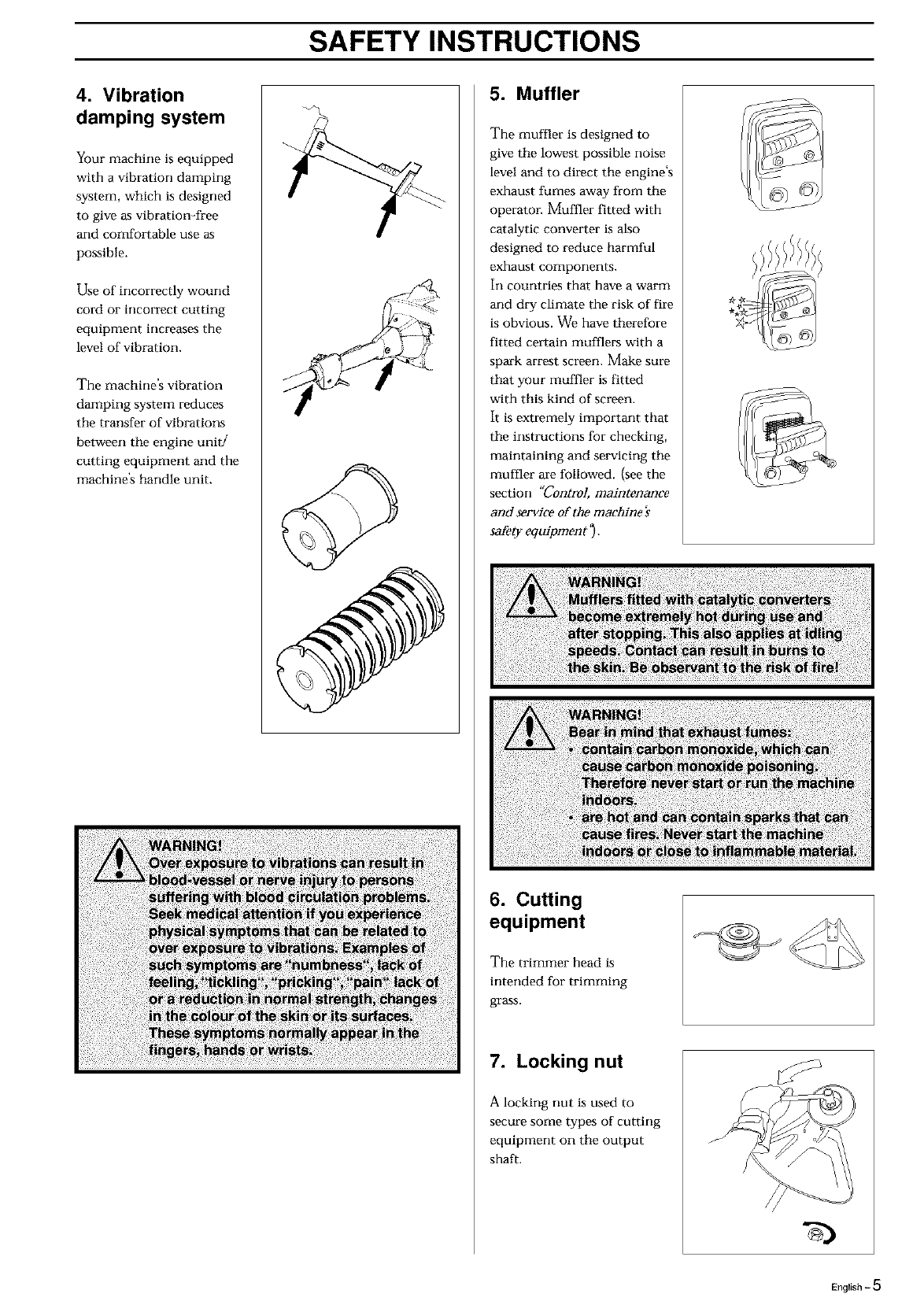
4. Vibration
damping system
Your machine is equipped
with a vibration damping
system, which is designed
to give as vibration-free
and comfortable use as
possible.
Use of incorrectly wourrd
cord or incorrect cutting
equipment increasas the
level of vibration.
The machine's vibration
damping system reduces
the transfer of vibrations
between tile engine unit/
cutting equipment and the
machine's handle unit.
5. Muffler
The muffler is designed to
give the lowest possible noise
level and to direct the engine's
exhaust fumes away from the
operatol: Muffier fitted with
catalytic converter is also
designed to reduce harmful
exhaust components.
In countries that have a warm
and dry climate the risk of fire
is obvious. We have therefore
fitted celtain mufflers with a
spark arrest screen. Make sure
that your muffler is fitted
with this kind of screen.
It is extremely important that
the instructions for checking,
maintaining and servicing the
muffler are followed. {see the
section "Control, maintenance
and service of the machine's
safety equipment _).
6. Cutting
equipment
The trimmer head is
intended for trimming
grass.
7. Locking nut
A locking nut is used to
secure some types of cutting
equipment on the output
shaft.
//////////
English -5

SAFETY INSTRUCTIONS
Control, maintenance and service of
the machine's safety equipment
IMPORTANT INFORMATION
All service and repairs to the machine require
special training.
This applies especially to the machine's safety
equipment. If the machine does not meet any
of the controls listed below you should
contact your service workshop.
The purchase of one of our products
guarantees that professional repair and
servicing will be carried out on it. If the point
of purchase is not one of our servicing deal
ers, please ask for details of the closest
service workshop.
1. Throttle trigger
lock
• Check that the throttle is
locked in tile "idling
position" when tile
throttle trigger lock is in
its original position.
• Press in the throttle
trigger lock and make sure
it returns to its original
position when released.
•Ensure that the throttle
and throttle trigger lock
move easily and that their
return spring systems
function.
• See section "Start". Start
the machine and apply
full throttle. Release the
throttle and check that the
cutting equipment stops
and remains at a standstill.
If the cutting equipment
rotates with the throttle in
the idling position then
the carburettor's idling
setting must be checked.
See chapter
"Maintenance ".
2. Stop switch
• Start the engine and make
sure that the engine stops
when the stop switch is
moved to the stop
position.
3. Cutting
attachment guard
• Ensure that the spray
guard is undamaged and
is not cracked.
• Replace the guard if it
has been exposed to
impact or is cracked.
• Always use the prescribed
blade an guard
combination, see chapter
"Teg_nigal data ".
4. Vibration
damping system
• Check the vibration
damping element
regularly for material
cracks and distortion.
• Check that the vibration
damping element is
undamaged and securely
attached.
5. Muffler
l. Never use a machine that
has a defective muffler.
2.Check regularly that the
muffler issecure.
3. If your muffler is fitted
with a spark arrest screen
then it should be cleaned
regularly. A blocked
screen leads to the engine
overheating with serious
damage as a result. Never
use a muffler with a
defective spark arrest
screen.
6-English
SAFETY INSTRUCTIONS
6. Cutting equipment
The section describes how through correct maintenance and
through using the right type of cutting equipment you can:
• Obtain naaximum clearing capacity.
• Increase the smwice life of the cutting equipment.
Two basic rules:
1)Only use the cutting
and guard equipment
we recommend! See
chapter "Te_nital
data ",
2)Check the cutting
equipment with regard
to damage and crack
formatiorL Damaged
cutting equipment
should always be
replaced.
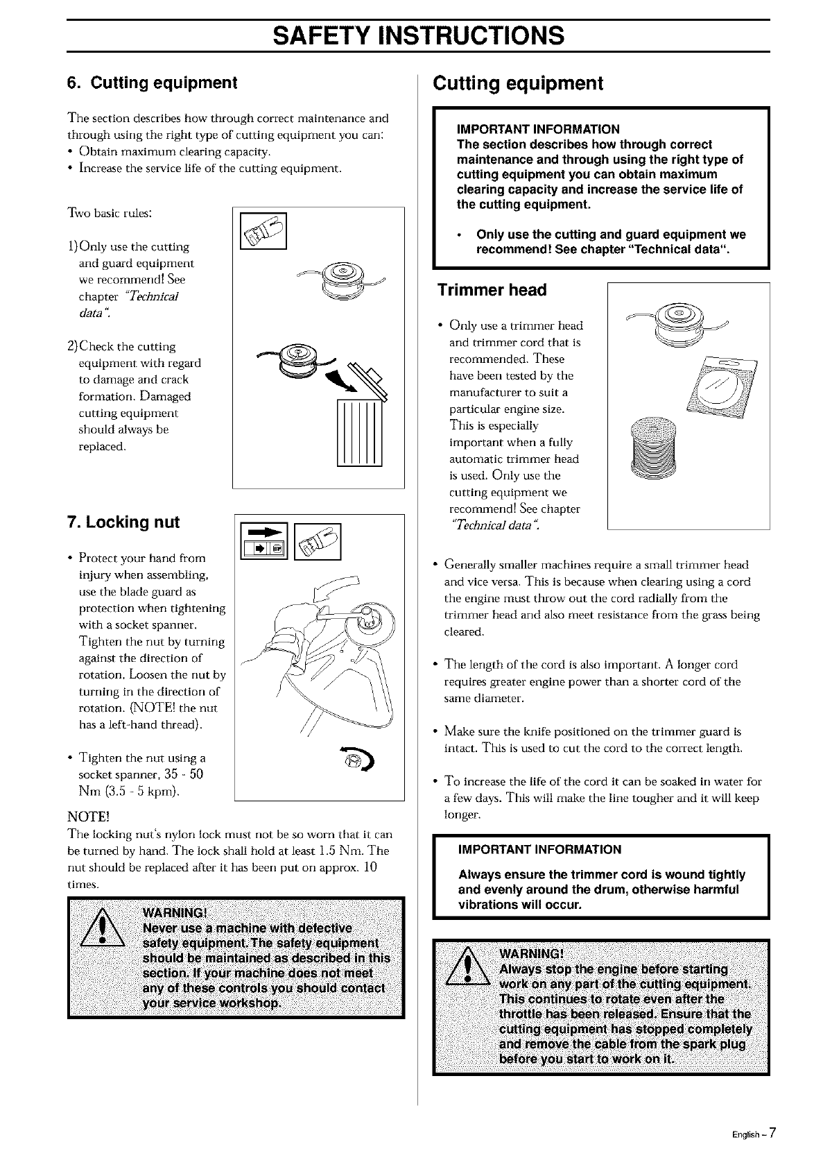
7. Locking nut
• Protect your hand from
injury when assecabling,
use the blade guard as
protection when tightening
with a socket spanner.
Tighten the nut by turning
against the direction of
rotation. Loosen the nut by
turning in the direction of
rotation. (NOTE[ the nut
has a left-hand thread).
• Tighten the nut using a
socket spanner, 35 - 50
Nm (3.5 - 5 kprn).
NOTE!
The locking nut's nylon lock must not be so worn that it can
be turned by hand. The lock shall hold at least 1.5 Nm. The
rmt should be replaced after it has been put on approx. 10
times.
Cutting equipment
IMPORTANT INFORMATION
The section describes how through correct
maintenance and through using the right type of
cutting equipment you can obtain maximum
clearing capacity and increase the service life of
the cutting equipment.
Only use the cutting and guard equipment we
recommend! See chapter "Technical data".
Trimmer head
• Only use a trimmer head
and trimmer cord that is
recommended. These
have been tested by the
manufacturer to suit a
particular engine size.
This is especially
important when a fully
automatic trimmer head
is used. Only use the
cutting equipment we
recommend! See chapter
"Technical data ",
Generally smaller machines require a small trimmer head
and vice versa. This is because when clearing using a cord
the engine must throw out the cord radially from the
trimmer head and also meet resistance from the grass being
cleared.
The length of the cord is also important. A longer cord
requires greater engine power than a shorter cord of the
same diameter.
Make sure the knife positioned on the trimmer guard is
intact. This is used to cut the cord to the correct length.
To increase the life of the cord it can be soaked in water for
a few days. This will make the line tougher and it will keep
longer.
IMPORTANT INFORMATION
Always ensure the trimmer cord is wound tightly
and evenly around the drum, otherwise harmful
vibrations will occur.
English - 7

SAFETY INSTRUCTIONS
General safety instructions
IMPORTANT INFORMATION
• The machine is only designed for trimming grass.
•The only accessories to be used with the engine
unit as a drive source are the cutting units we
recommend in the chapter "Technical data ".
•Never use the machine if you are tired, if you
have consumed alcohol, or if you are taking
medicines that can affect your sight, your
judgement or the control of your body.
•Use personal protective equipment. See the
section "Personal protective equipment"
•Never use a machine that has been modified so
that it no longer corresponds with the original
design.
•Never use a machine that is faulty. Follow the
maintenance, control and service instructions in
this Operator's Manual. Some maintenance and
service actions should be carried out by trained
and qualified specialists. See the chapter
"Maintenance"
•All covers and guards must be fitted before
starting the machine. Check that the spark plug
cap and HT lead are not damaged, otherwise you
could get an electric shock.
•The machine operator shall ensure, while
working, that no persons or animals come closer
than 15 metres (50 feet). When several operators
are working in the same area the safety distance
should be at least double tree length, however, at
least 15 metres (50 feet).
Start
•The complete clutch cover with shaft must be fitted before
the machine is started, othmwvise the clutch can become
loose and cause personal injury.
• Never start the machine indoors. Bear in mind the dangers
of inhaling the engine's exhaust fumes.
• Observe your surroundings and make sure that there is no
risk of people or animals coming into contact with the
cutting equipment.
• Place the machine on the (_
ground, ensure the cutting
equipment runs free of
twigs and stones. Push the
machine body towards the
ground using your left
hand. (NOTE[ Not with
your foot). Grip the starter
handle with your right
hand and pull the
startercord.
Fuel safety
• Always use a fuel container
with an anti-spill valve.
• Never fill the machine
while the engine is
running. Always stop the
engine and let it cool for a
few minutes before
refuelling.
• Provide good ventilation
when filling or mixing fuel
(petrol and 2-stroke oil).
•Move the machine at least
3 m from the filling
position before starting.
•Never start the machine:
a)If you have spilt fuel on it.
Wipe up all spillage.
b)If you have spilt fuel on
yourself or your clothes.
Change your clothes.
c) If there is a fuel leak.
Make regular checks for
leakage from tile fuel cap
and the fuel supply pipes.
Min. 3 m J_
(10 ft) I
Transport and storage
• Store and transpolt tile machine and fuel so that any leakage
or fumes do not risk coming into contact with sparks or
naked flames. For example, electric machines, electric
motors, electrical switches/power switches, heaters or the
like.
• When storing and transpolting fuel approved containers
intended for this purpose must be used.
• When storing the machine for long periods the fuel tank
must be emptied. Contact your local petrol station to find
out how to dispose of excess fuel.
8 - English
SAFETY INSTRUCTIONS
General working instructions
IMPORTANT INFORMATION
This section takes up the basic safety
precautions for working with the trimmer.
if you encounter a situation where you are
uncertain how to proceed you should ask an
expert. Contact your dealer or your service
workshop.
Avoid all usage which you consider to be
beyond your capability.
Basic safety precautions
l. Observe your surroundings:
•To ensure that people, animals or other things carmot affect
your control of the machine.
•To ensure that the above mentioned do not come into
contact with the cutting equipment or objects that can be
thrown by the cutting equipment.
•NOTE! Never use a machine without the possibility of
calling for help in the event of an accident.
2. Avoid usage in
unfavourable weather
conditions. For example,
thick fog, heavy rain,
strong winds or extreme
cold, etc. To work in bad
weather conditions is
tiring and can create
dangerous circumstances,
e.g. slippery surfaces.
3. Make sure you can walk
and stand safely. Look out
for any obstacles with
unexpected movement
(roots, stones, branches,
pits, ditches, etc.). Take
great care when working
on sloping ground.
4. The engine should be switched off before moving. When
moving over longer distances and transpolting the transport
guard should be used.
5. Never put the machine down with the engine rurming
unless you have good sight of it.
6. Do not over-reach
7. Keep Cutting attachment below waist level.
Basic working techniques
• Always drop to idling speed after each working operation.
Longer periods rurming at full throttle without loading the
engine (that is without resistance, which the engine feels
from the cutting equipment when trimming) can lead to
serious engine damage.
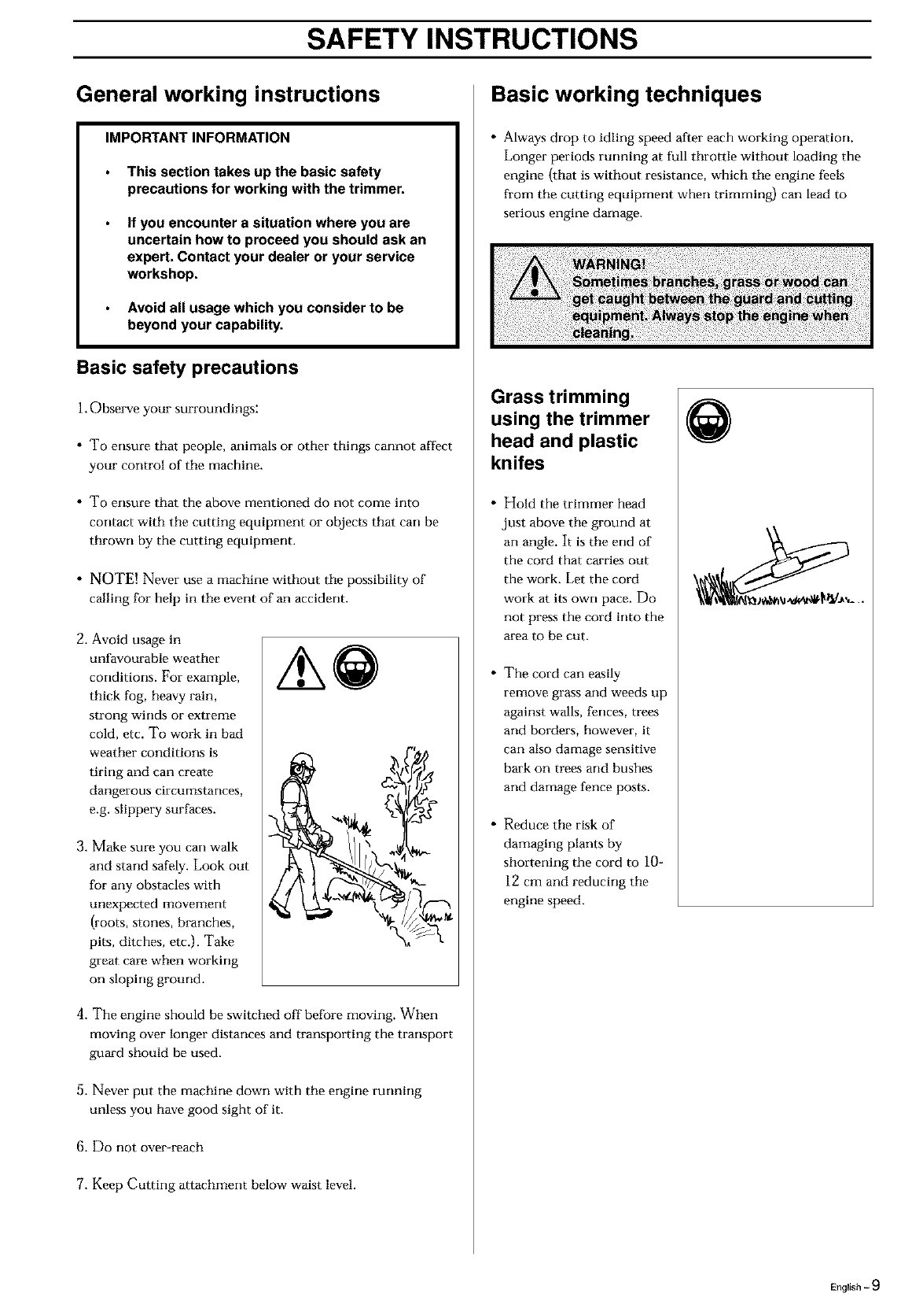
Grass trimming
using the trimmer
head and plastic
knifes
• Hold the trimmer head
just above the ground at
an angle. It is the end of
the cord that carries out
the work. Let the cord
work at its own pace. Do
not press the cord into the
area to be cut.
• The cord can easily
remove grass and weeds up
against walls, fences, trees
arm borders, however, it
can also damage sensitive
bark on trees and bushes
arm damage fence posts.
• Reduce the risk of
damaging plants by
sholtening the cord to 10-
12 cm and reducing the
engine speed.
Q
English -9
SAFETY INSTRUCTIONS
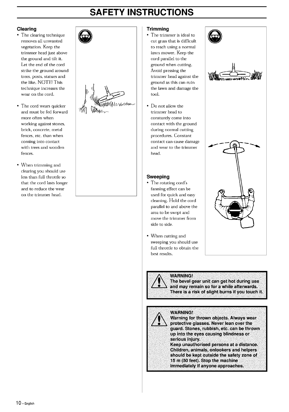
Clearing
• The clearing technique
removes all unwanted
vegetation. Keep tile
trimmer head just above
the ground and tilt it.
Let the end of the cord
strike the ground around
trees, posts, statues and
the like. NOTE! This
technique increases the
wear on the cord.
• The cord wears quicker
and must be fed fol_vard
more often when
working against stones,
brick, concrete, metal
fences, etc. than when
coming into contact
with trees and wooden
fences.
• When trimming and
clearing you should use
less than full throttle so
that tile cord lasts longer
and to reduce tile wear
on the trimmer head.
@Trimming
• The trimmer is ideal to
cut grass that is difficult
to reach using a normal
lawn mower. Keep the
cord parallel to tile
ground when cutting.
Avoid pressing tile
trimmer head against the
ground as this can ruin
the lawn and damage the
tool.
• Do not allow the
trimmer head to
constantly come into
contact with the ground
during normal cutting
procedures. Constant
contact can cause damage
and wear to the trimmer
head.
Sweeping
• The rotating cord's
farming effect can be
used for quick and easy
cleaning. Hold the cord
parallel to and above the
area to be swept and
move the trimmer from
side to side.
• When cutting and
sweeping you should use
full throttle to obtain the
best results.
@
10-English

WHAT IS WHAT?
LD/LxT/LDx
® ®
®\
®
What is what on the trimmer?
], Trimmer head
2. Grease filler cap
3. Angle gear
4. Spray guard
5, Shaft
6. Loop handlebar
7. Throttle
8, Stop switch
9, Throttle trigger lock
10. Cylinder cover
11. Starter handle
12. Fuel tank
13. Choke
14. Air purge
15. Air filter cover
16. Clutch cover
17. Handlebar adjustment
18, Locking nut
19. Support flange
20. Drive disc
21, Socket spanner
22, Operator's Manual
23. Allen key
24, Locking pin
25, Shaft coupling
En_l_,h-11

ASSEMBLY
Assembling the loop handlebar
(325C, 325Cx)
• Position the handle on
the shaft. Note that the
handle must be mounted
below the arrow on the
shaft.
•Fit tile bolt, securing plate
and wing nut as shown in
the diagram.
• Tighten the wing nut.
Assembling the loop handlebar
(322L, 323L, 325Lx, 325Lxv 325LDx)
• Clip the loop handle onto
the shaft. Note that the
loop handle must be
fitted between the arrows
on the shaft.
• Slide the spacer into the
slot in the loop handle.
• 322L/323L: Fit the nut,
washer and bolt.
325Lx/325Lx/325LDx:
Fit tile nut, knob and
bolt. Do not overtighten.
•Now adjust the trimmer
to give a comfortable
working position. Tighten
the bolt/knob.
Assembling and dismantling the
two-part shaft (325Lxv 325LDx)
Assembling:
• Make sure the handle is
loose.
• Guide tile cut-out on the
lower section of the shaft
into the coupling's
locking plate on the
upper section of the
shaft. The sections are
then locked together.
• Tighten the handle.
Dismantling
• Undo the handle (at least
three turns).
• Press the handle towards
the coupling.
• Carefully twist the lower
section out of the lock.
• Hold both parts of the
shaft and pull out the
lower section from the
coupling.
Assembly of the trimmer head
It is extremely important
that the disc drive's/support
flange's guide engages
correctly in tile cutting
equipment's centre hole
when assembling the cutting
equipment. Cutting
equipment assembled
incorrectly can result in
serious and/or fatal personal
injury.
12 - English

ASSEMBLY
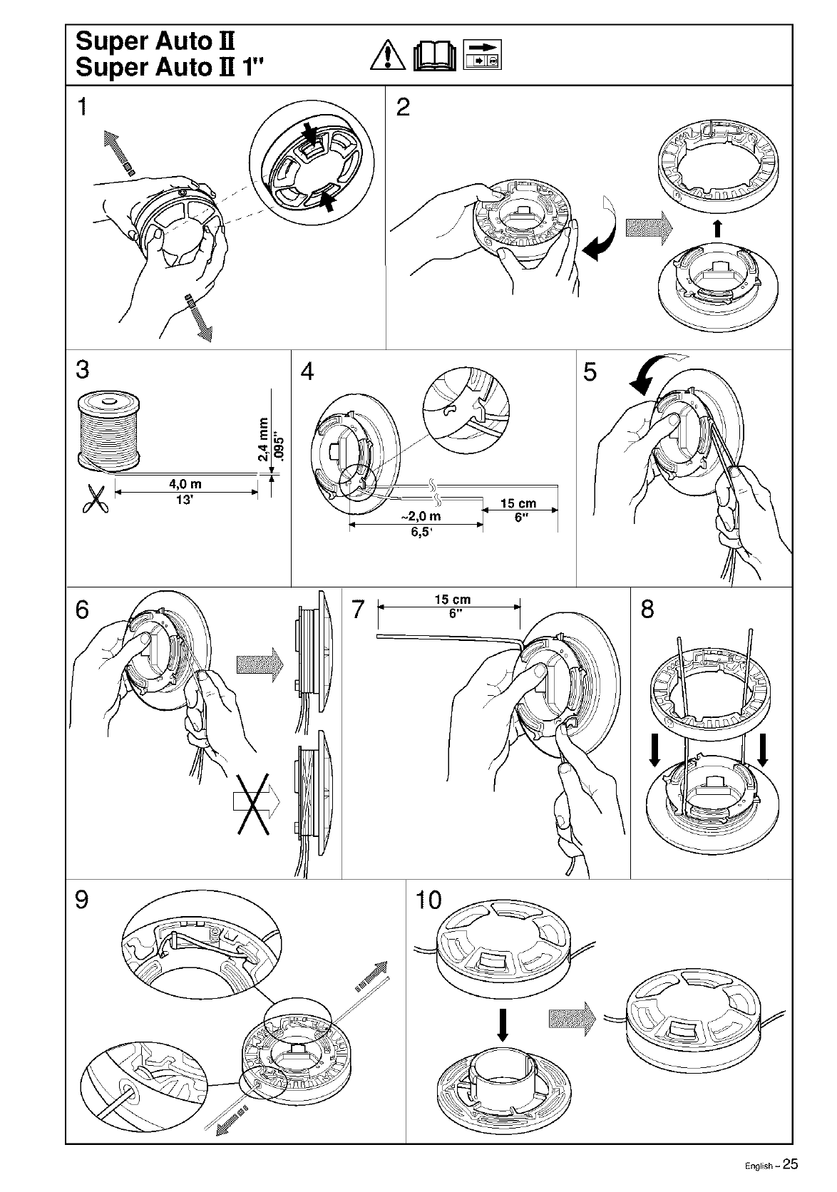
Assembling the spray guard and
trimmer head Superauto II
(322L, 323L, 325Lx, 325LxT, 325LDx)
• Fit the appropriate guard
(A) for use with the
trimmer head. Hook the
guard onto the shaft fitting
and secure it with the bolt
(L).
• Fit the drive disc (B) on the
output axle.
• Turn the blade axle until
one of the holes in tile
drive disc aligns with the
hole in the gear housing.
• Insert the locking pin (C)
in the hole so that the axle
is locked.
• The trimmer head must be
split to be fitted (see the
diagram). Proceed as
follows:
• Insert your finger into the
centre hole of the cover (I)
at the same time as you
hold the cover with your
other fingers, Press the two
catches (J) that extend from
the cut-out on the bottom
section (14_)using the
thumb and index finger of
your other hand. Press
apart the trimmer head
using the fingers on the
cover.
• Place the cover (I) and the
support flange (P) on the
output axle.
• Fit the nut (G). The
tightening torque of the
nut is 35-50 Nm (3.5-5
kpm). Use the socket
spanner in the tool kit.
Hold the handle of the
spanner as close to the
trimmer guard as possible.
The nut is tightened when
the spanner is turned
against the direction of
rotation (left-hand thread).
• Fit the trimmer head's
bottom section (K) on the
cover (I) by pressing the
two sections together with
the cut-outs on the bottom
section aligned with the
catches on the cover.
• To dismantle follow the
instructions in the reverse
order.
L
Assembling other guards and cutting
equipment
(322L, 323L, 325Lx, 325LxT, 325LDx)
• Fit the appropriate guard
(A) for use with the
trimmer head. Hook the
guard onto the shaft
fitting and secure it with
the bolt (L).
• Fit the disc drive (B) on
the output axle.
• Turn tile blade axle until
one of the disc drive's
holes aligns with the
corresponding hole in
the gear housing.
• Insmt the locking pin
(C) into the hole to lock
the axle.
• Screw on the trimmer
head (H) in the direction
of rotation.
• Dismantling takes place
>-,_ \
Fitting the spray guard and trimmer
head (325C)
Guard
• Fit the guard as shown
in the diagram, Tighten
securely,
Trimmer head
• Fit the dust cup on the
shaft. The nut must be
completely covered by
the dust cup.
• Hold the dust cup with
a sparmer to prevent the
shaft from rotating.
• Screw tile trimmer head
onto the shaft,
®
®
English -13
ASSEMBLY
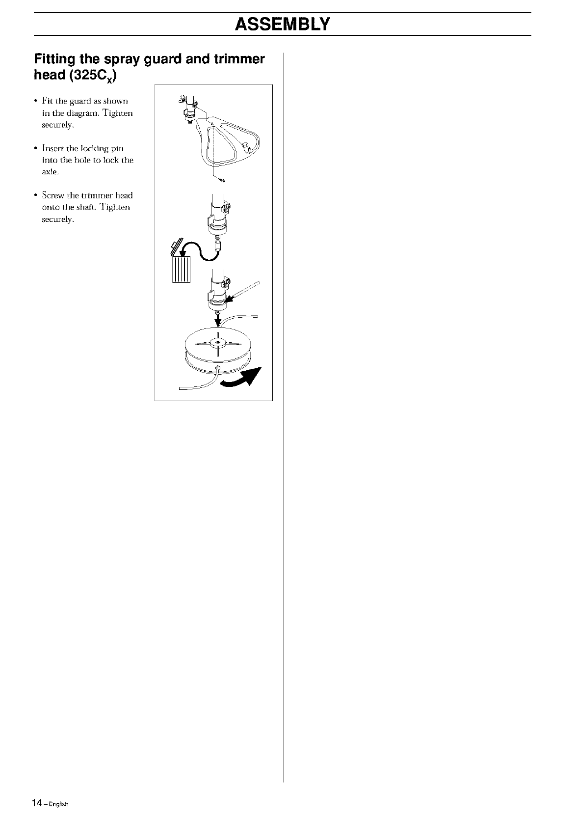
Fitting the spray guard and trimmer
head (325Cx)
•Fit the guard as shown
in the diagram. Tighten
securely.
• Insert the locking pin
into the hole to lock the
axle.
• Screw the trimmer head
onto the shaft. Tighten
securely.
14- English
FUEL HANDLING
Fuel mixture
NOTE!
The machine is fitted with a two-stroke engine and must
always be run on a mixture of gasoline and two-stroke oil. It is
important to measure the quantity of oil accurately, to ensure
the correct mixture ratio. Small discrepancies in the amount of
oil have a great bearing on the proportions of the fuel mixture
when mixing small amounts of fuel.
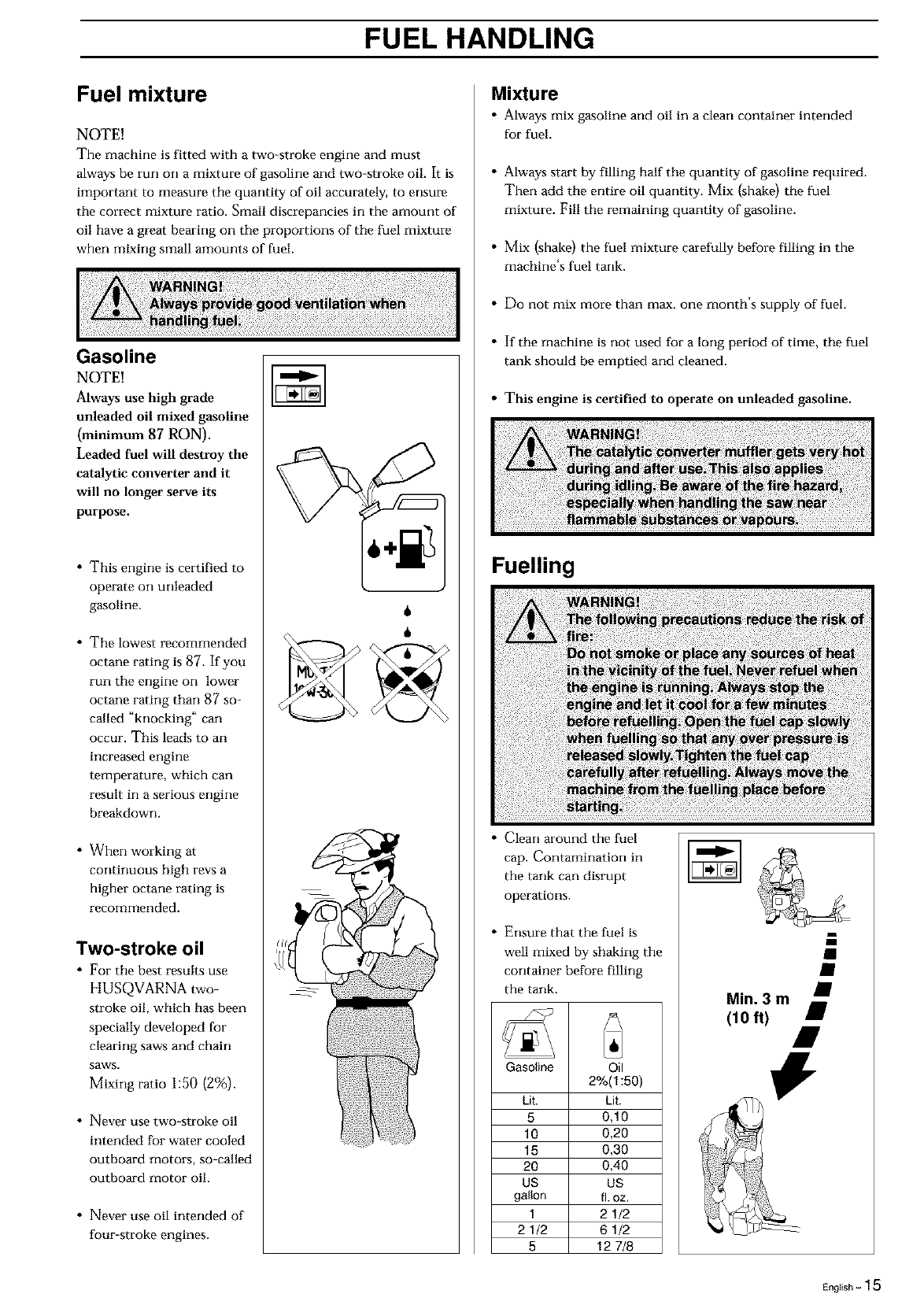
Gasoline
NOTE!
Always use high grade
unleaded oil mixed gasoline
(minimum 87 RON).
Leaded fuel will destroy the
catalytic converter and it
will no longer serve its
purpose.
• This engine is certified to
operate on unleaded
gasoline.
• The lowest recommended
octane rating is 87. If you
run the engine on lower
octane rating than 87 so=
called "knocking" can
occur. This leads to an
increased engine
temperature, which can
result in a serious engine
breakdowrL
• When working at
continuous high revs a
higher octane rating is
recommended.
Two-stroke oil
•For the best results use
HUSQVARNA two-
stroke oil, which has been
specially developed for
clearing saws and chain
saws.
Mixing ratio 1:50 (2%).
• Never use two-stroke oil
intended for water cooled
outboard motors, so-called
outboard motor oil.
• Never use oil intended of
four-stroke engines.
6
6
Mixture
• Always mix gasoline and oil in a clean container intended
for fuel.
• Always start by filling half the quantity of gasoline required.
Then add the entire oil quantity. Mix (shake) the fuel
mixture. Fill the remaining quantity of gasoline.
• Mix (shake) the fuel mixture carefully before filling in the
machirm's fuel tank.
• Do not mix more than max. one month's supply of fuel.
• If the machine is not used for a long period of time, the fuel
tank should be emptied and cleaned.
•This engine is certified to operate on unleaded gasoline.
Fuelling
• Clean around the fuel
cap. Contamination in
the tank can disrupt
operations.
• Ensure that the fuel is
Min. 3 m ;
(10 ft) #
well mixed by shaking the
container before filling
the tank.
Gasoline Oil
2%(1:50)
Lit. Lit.
5 0,10
10 0,20
15 0,30
20 0,40
US US
gallon fl. oz.
1 21/2
2 1/2 6 1/2
5 12 7/8
English - 1 5
START AND STOP
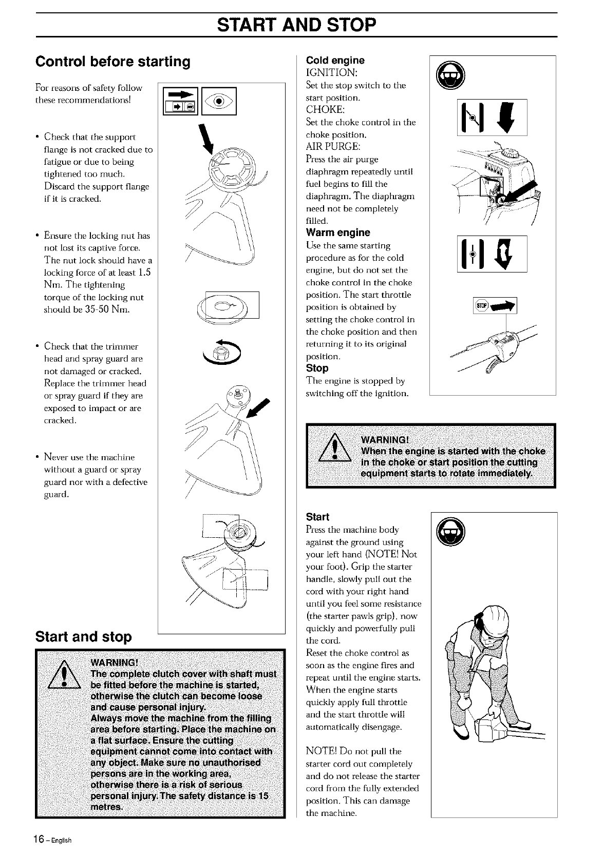
Control before starting
For reasons of safety follow
these recommendations!
• Check that the suppoxt
flange is not cracked due to
fatigue or due to being
tightened too much.
Discard the support flange
if it is cracked.
• Ensure the locking rmt has
not lost its captive force.
The rmt lock should have a
locking force of at least 1.5
Nm. The tightening
torque of tile locking nut
should be 35-50 Nm.
• Check that the trimmer
head and spray guard are
not damaged or cracked.
Replace the trimmer head
or spray guard if they are
exposed to impact or are
cracked.
• Never use the machine
without a guard or spray
guard nor with a defective
guard.
Start and stop
/
Cold engine
IGNITION:
Set the stop switch to the
start position.
CHOKE:
Set the choke control in the
choke position.
AIR PURGE:
Press the air purge
diaphragm re.peatedly until
fuel begins to fill the
diaphragm. The diaphragm
need not be completely
filled.
Warm engine
Use the same starting
procedure as for the cold
engine, but do not set the
choke control in the choke
position. The strut throttle
position is obtained by
setting the choke control in
the choke position and then
returning it to its original
position.
Stop
The engine is stopped by
switching off the ignition.
Start
Press the machine body
against the ground using
your left hand (NOTE! Not
your foot). Grip the starter
handle, slowly pull out the
cord with your right hand
until you feel some resistance
(the starter pawls grip), now
quickly and powerfully pull
the cord.
Reset the choke control as
soon as the engine fires and
repeat until the engine starts.
When the engine starts
quickly apply full throttle
and the stait throttle will
automatically disengage.
NOTE! Do not pull the
starter cord out completely
and do not release the starter
cord from the fully extended
position. This can damage
the machine.
I+1!t
Q
16- English
MAINTENANCE
Carburetor
Your Husqvarna product has been designed and crlanufactured
to specifications that reduce harmful emissions.
After your unit has been run 8-10 tanks of fuel the engine has
broken in, To ensure that your unit is at peak performance and
producing the least amount of harmful emissions after break
in, have your authorized servicing dealer, who has a revolution
counter at his disposal, to adjust your carburetor for optimum
operating conditions.
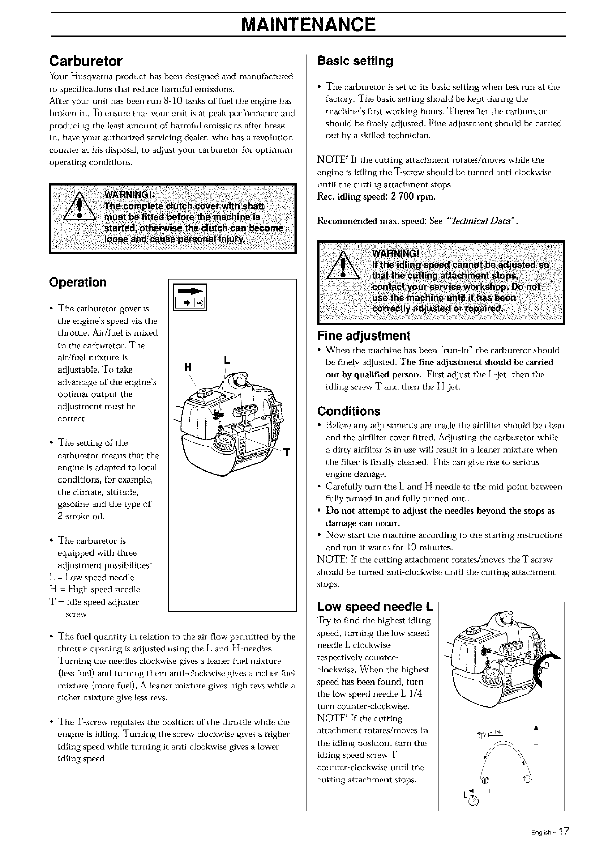
Operation
• The carburetor governs
the engine's speed via the
throttle. Air/fuel is mixed
in the carburetor. The
air/fuel mixture is
adjustable. To take
advantage of the engine's
optimal output the
adjustment must be
correct.
• The setting of the
carburetor means that the
engine is adapted to local
conditions, for example,
the climate, altitude,
gasoline and the type of
2-stroke oil.
• The carburetor is
equipped with three
adjustment possibilities:
L = Low speed needle
H = High speed needle
T= Idle speed adjuster
screw
HL
• The fuel quantity in relation to the air flow permitted by the
throttle opening is adjusted using the L and H-needles.
Turning the needles clockwise gives a leaner fuel mixture
(less fuel) and turning them anti-clockwise gives a richer fuel
mixture (more fuel). A leaner mixture gives high revs while a
richer mixture give less revs.
• The T-screw regulates the position of the throttle while the
engine is idling. Turning the screw clockwise gives a higher
idling speed while turning it anti-clockwise gives a lower
idling speed.
Basic setting
• The carburetor is set to its basic setting when test run at the
factory. The basic setting should be kept during the
machine's first working hours. Thereafter the carburetor
should be finely adjusted. Fine adjustment should be carried
out by a skilled technician.
NOTE! If the cutting attachment rotates/moves while the
engine is idling the T-screw should be turned anti-clockwise
until the cutting attachment stops.
Rec. idling speed: 2700 rpm.
Recommended max. speed: See "Technical Data'.
Fine adjustment
• When the machine has been "run-in" the carburetor should
be finely adjusted. The fine adjustment should be carried
out by qualified person. First adjust the Ljet, then the
idling screw Tand then the H-jet.
Conditions
• Before any adjustments are made the airfilter should be clean
and the airfilter cover fitted. Adjusting the carburetor while
a dirty airfilter is in use will result in a leaner mixture when
the filter is finally cleaned. This can give rise to serious
engine damage.
• Carefully turn the L and H needle to the mid point between
fully turned in and fully turned out..
• Do not attempt to adjust the needles beyond the stops as
damage can occur.
•Now start the machine according to the starting instructions
and run it warm for i0 minutes.
NOTE! If the cutting attachment rotates/moves the Tscrew
should be turned anti-clockwise until the cutting attachment
stops.
Low speed needle L
Try to find the highest idling
speed, turning the low speed
needle L clockwise
respectively counter-
clockwise, When the highest
speed has been found, turn
the low speed needle L 1/4
turn counter-clockwise.
NOTE! If the cutting
attachment rotates/moves in
the idling position, turn the
idling speed screw T
counter-clockwise until the
cutting attachment stops.
En_,,h-17

MAINTENANCE
Final setting of the idling speed T
Adjust the idling speed with
the screw T, if it is necessary
to readjust. First turn the
idle speed adjusting screw T
clockwise until the cutting
attachment starts to rotate/
move.
Then turn, counter-clock-
wise until the cutting
attachment stops, a corre.ctly
adjusted idle speed setting
occm_ when the engine runs
smoothly in every position.
It should also be good
margin to the rpm when the
cutting attachment starts to
rotate/move.
CAUTION! Contact your setwicing dealer, if the idle speed
setting cannot be adjusted so that the cutting attachment
stops. Do not use the machine until it has been properly
adjusted or repaired.
High speed needle
H
The high speed needle
affects the machine's power,
speed, temperature, and fuel
consumption, a too lean
adjustment on the high
speed needle H (the high
speed needle H is screwed in
too much) gives a too high
speed resulting in engine
damage. Do not allow the
engine to run at full speed
for more than 10 seconds.
Apply full throttle and turn
the high speed needle H
slowly anticlockwise until
the engine runs unevenly.
The high speed needle H is
then turned slowly
clockwise a little until the
engine runs smoothly.
Note the engine should be
run unloaded when
adjusting the high speed
needle.
Therefore dismantle the cutting equipment, nut, support
flange and disc drive before adjusting the high speed needle.
The high speed needle is adjusted correctly when the machine
'splatters' a little. If the machine smokes heavily at the same
time as it 'splatters' heavily the adjustment is too rich.
NOTE! For optimum setting of the carburetor, contact a
qualified servicing dealer who has a revolution counter at his
disposal.
Correctly adjusted carburetor
Acorrectly adjusted carburetor means that the machine
accelerates without hesitation and the machine 4-cyclas a little
at max speed. Furthermore, the cutting attachment must not
rotate/move at idling. A too lean adjusted low speed needle L
may cause starting difficulties and bad acceleration.
Atoo lean adjusted high speed needle H gives lower power =
less capacity, bad acceleration and/or damage to the engine.
Atoo rich adjustment of the two speed needles L and H gives
acceleration problems or too low working speed.
18-English
MAINTENANCE
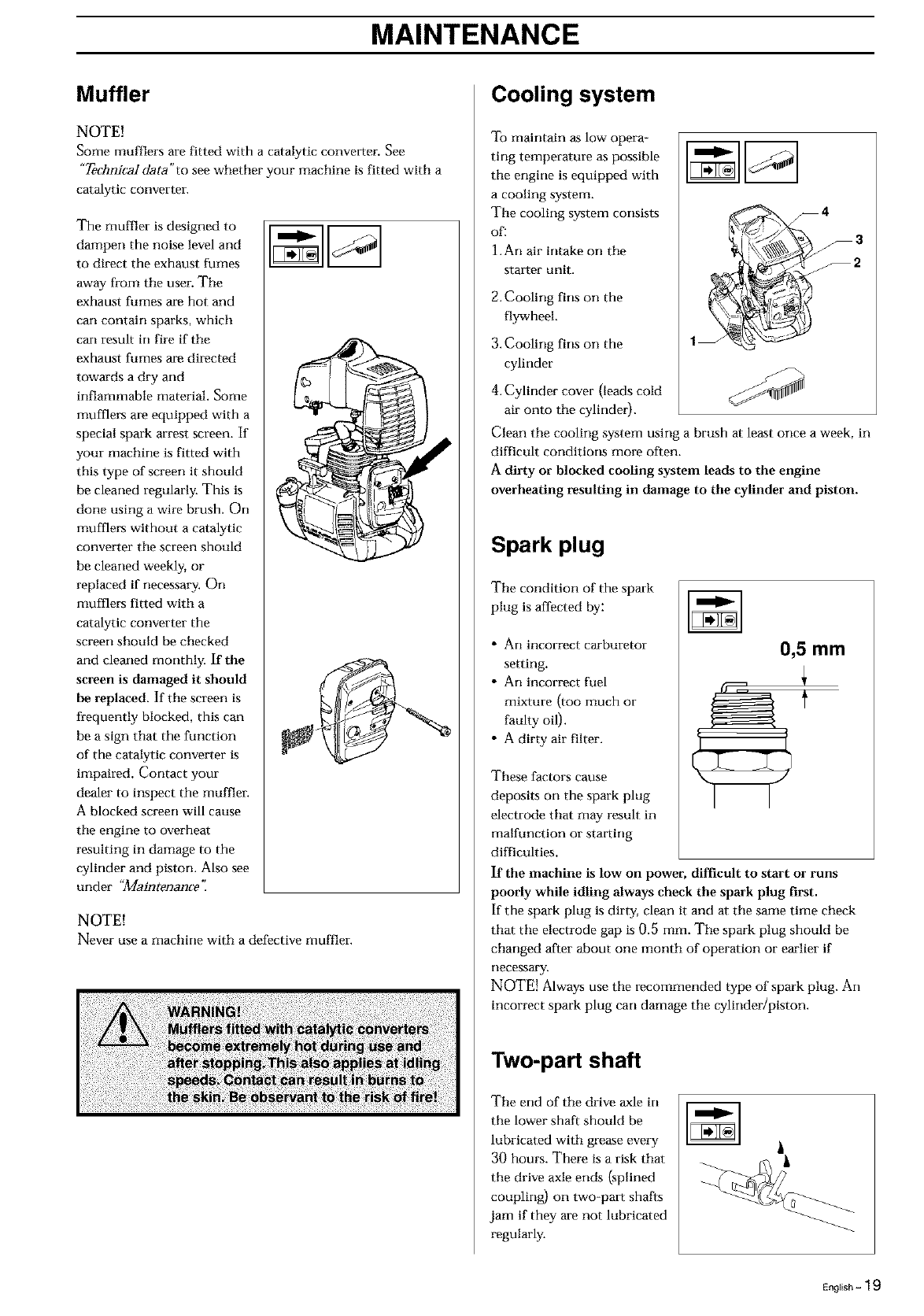
Muffler
NOTE!
Some mufflers are fitted with a catalytic convelter. See
"Ted_ni_aI data"to see whether your machine is fitted with a
catalytic converter.
The muffler is designed to
dampen the noise level and
to direct the exhaust fumes
away from the user. The
exhaust fumes are hot and
can contain sparks, which
can result in fire if the
exhaust fumes are directed
towards a dry and
inflammable material. Some
mufflers are equipped with a
special spark arrest screen. If
your machine is fitted with
this type of screen it should
be cleaned regularly. This is
done using a wire brush. On
mufflers without a catalytic
converter the screen should
be cleaned weekly, or
replaced if necessary. On
mufflers fitted with a
catalytic converter the
screen should be checked
and cleaned monthly. If the
screen is damaged it should
he replaced. If the screen is
frequently blocked, this can
be a sign that the function
of the catalytic converter is
impaired. Contact your
dealer to inspect the muffler.
A blocked screen will cause
the engine to overheat
resulting in damage to the
cylinder and piston. Also see
under "aaintenanee '_
NOTE!
Never use a machine with a defpctive muffles-.
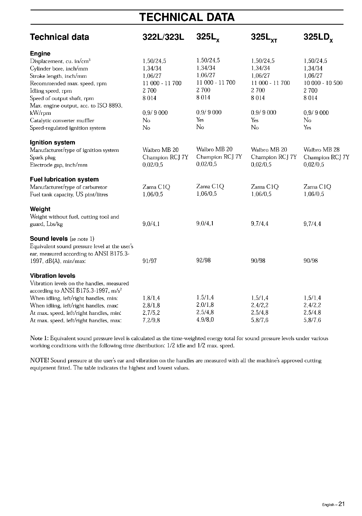
Cooling system
To maintain as low opera-
ring temperature as possible
the engine is equipped with
a cooling system.
The cooling system consists
of:
1.An air intake on the
staster unit.
2. Cooling fins on the
flywheel.
3.Cooling fins on the
cylinder
4. Cylinder cover (leads cold
air onto the cylinder).
Clean the cooling system using a brush at least once a week, in
difficult conditions more often.
Adirty or blocked cooling system leads to the engine
overheating resulting in damage to the cylinder and piston.
Spark plug
The condition of the spark
plug is affected by:
• An incorrect carburetor
setting.
• An incorrect fuel
mixture (too much or
faulty oil).
• A dirty air filter.
These factors cause
deposits on the spark plug
electrode that may result in
malfunction or stasting
difficulties.
If the machine is low on power, difficult to start or runs
poorly while idling always check the spark plug first.
If the spark plug is dirty, clean it and at the same time check
that the electrode gap is 0.5 mm. The spark plug should be
changed after about one month of operation or earlier if
necassary.
NOTE! Always use the re.commended type of spark plug. An
incorrect spark plug can damage the cylinder/piston.
Two-part shaft
The end of the drive axle in
the lower shaft should be
lubricated with grease every
30 hours. There is a risk that
the drive axle ends (splined
coupling) on two-past shafts
jam if they are not lubricated
regularly.
English - 1 9

MAINTENANCE
Air filter
The air filter should be
cleaned regularly removing
dust and dirt to avoid:
• carburetor malfunction
• starting problems
• reduced engine power
• unnecessal3r wear to
engine parts
• abnormal fuel
consumption
Clean the filter after every
25 hom.'s or more regularly
if operating conditions are
exceptionally dusty.
Cleaning the air filter
Dismantle the air filter cover and remove tbe air filter. Wasb in
clean, warm soapy water. Ensure that the filter is dry before
refitting. An air filter used for a long period of time can never
be cleaned completely. Therefore it is rmcessary to replace the
filter from time to time with a new filter. A damaged air filter
must always be replaced.
If the machine is used in dusty conditions the air filter
should be soaked in oil, see the section on "OillngtheMr
filter'.
Oiling the air filter
Always use HUSQVARNA _------_----_
filter oil, order no. 503 47
73-01. The filter oil
contains a solvent to make
it spread evenly through
the filter. You should
therefore avoid skin
contact. Put the filter in a
plastic bag and the pour
the filter oil over it. Knead
the plastic bag to distribute
the oil. Squeeze the excess
oil out of the filter inside
the plastic bag and pour
off the excess before fitting
the filter on the machine. Never use common engine oil. This
would drain through the filter quite quickly and collect in the
bottom.
Angle gear
(322L, 323L, 325Lx, 325Lxv 325LDx)
The angle gear is filled with a
sufficient quantity of grease
at tile factol3_ However,
before using the machine you
should check that the angle
gear is filled to 3/4 with
grease. Use special grease.
Normally, the grease do_ not
need to be changed except
when repails are cm-ried out.
NOTE: Use only HUSQVARNA replacement parts. Use of
other brands of replacement parts can cause damage to your
unit or injury to the operator or others. Your warranty does
not cover damage or liability caused by the use of accessories
and/or attachments not specifically recommended by
HUSQVARNA.
Maintenance schedule
Below you will find soi'rle general i'aaintenance instructions.
Daily maintenance
Check tbrottle trigger and throttle trigger lockout function.
Check stop switch functiorL
Check that blade/trimmer head does not rotate at idling.
Clean the exterior of the machine.
Check that the harness is undamaged.
Check the guard for damage or cracks.
Change the guard in case of impacts or cracks.
Check the trimmer head for cracks and chips or damage.
Replace if necessary.
• A non-balanced blade/trimmer head induces heavy
vibrations that may damage the machine.
• Check that the locking nut is sufficiently tightened.
• Check that nuts and screws are sufficiently tightened.
Weekly maintenance
• Check the starter, especially cord and return spring.
• Clean the carburetor area.
• Clean the exterior of the spark plug.
• Remove it and check the electrode gap.
•Adjust it to 0,5 mm (.020"), or change the spark plug.
• Clean the cooling fins on the cylinder and check that the air
intake at the starter is not clogged.
• Check that the angle gear is filled with grease up to 3/4. Use
special grease.
• Clean the air filter.
• Clean or replace the muffler's spark arrest screen (only
mufflers with a catalytic converter).
Monthly maintenance
• Clean the fuel tank.
• Clean the exterior of the carburetor and the space around it.
• Clean the fan and the space around it.
• Check fuel hose for cracks or other damage. Change if
necessary.
• Change fuel filter in fuel tank.
• Check clutch, clutch spring and clutch drum for wear.
Change if necessary.
• Check electrical wires and connections.
• Change the spark plug.
• Change the airfilter.
• Check and clean the muffler's spark arrest screen if necessary
(only mufflers with a catalytic converter).
20 - English
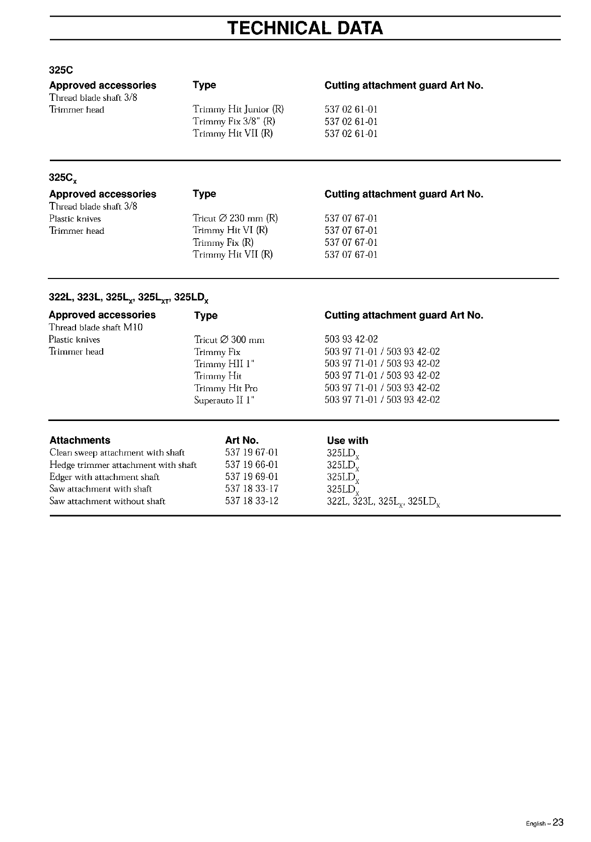
TECHNICAL DATA
Technical data
Engine
Displacement, cu. in/cm 3
Cylinder bore, incb/mm
Stroke length, incb/mm
Recommended max. speed, rpm
Idling speed, rpm
Speed of output shaft, rpm
Max. engine output, acc. to ISO 8893,
kW/rpm
Catalytic converter muffler
Speed-regulated ignition system
Ignition system
Manufacturer/type of ignition system
Spark plug
Electrode gap, incb/mm
Fuel lubrication system
Manufacturer/type of carburetor
Fuel tank capacity, US pintJlitres
Weight
Weight without fuel, cutting tool arm
guard, Lbs/kg
Sound levels (se note i)
Equivalent sound pressure level at the user's
ear, measured according to ANSI B175.3-
1997, dB(A), min/max:
322L/323L 325L x 325LxT 325LD x
1,50/24,5 1,50/24,5 1,50/24,5 1,50/24,5
1,34/34 1,34/34 1,34/34 1,34/34
1,06/27 1,06/27 1,06/27 1,06/27
11000-11700 11000-11700 11000-11700 10000-10500
2 700 2 700 2 700 2 700
8014 8014 8014 8014
0,9/9 000 0,91 9 000 0,9/9 000 0,9/9 000
No Yes Yes No
No No No Yes
Walbro MB 20 Walbro MB 20 Walbro MB 20 Walbro MB 28
Champion RCJ 7Y Champion RCJ 7Y Champion RCJ 7Y Champion RCJ 7Y
0,02/0,5 0,02/0,5 0,02/0,5 0,02/0,5
Zama C 1Q Zama C i Q Zama C 1Q Zama C 1Q
1,06/0,5 1,0610,5 1,06/0,5 1,06/0,5
9,0/4,1 9,014,1 9,7/4,4 9,7/4,4
91/97 92/98 90/98 90/98
Vibration levels
Vibration levels on the handles, measured
according to ANSI B175.3-1997, m/s _
When idling, left/right handles, min: 1,8/i,4
When idling, left/right handles, max: 2,8/i,8
At max. speed, left/right handles, min: 2,7/5,2
At max. speed, left/right handles, max: 7,2/9,8
1,5/1,4 1,5/i,4 1,5/i,4
2,0/1,8 2,4/22 2,4/22
2,5/4,8 2,5/4,8 2,5/4,8
4,9/8,0 5,8/7,6 5,8/7,6
Note 1: Equivalent sound pressure level is calculated as the time-weighted energy total for sound pressure levels under various
working conditions with the following time distribution: 1/2 idle and 1/2 max. speed.
NOTE[ Sound pressure at the user's ear and vibration on the handles are measured with all the machine's approved cutting
equipment fitted. The table indicates the highest arm lowest values.
English - 21

TECHNICAL DATA
Technical data
Engine
Displacement, cu. in/cm 3
Cylinder bore, inc_mm
Stroke length, inch/mm
Recommended max, speed, rpm
Idling speed, rpm
Speed of output shaft, rpm
Max. engine output, acc. to ISO 8893
kW/rpm
Catalytic converter muffler
Speed-regulated ignition system
Ignition system
Marmfacturer/type of ignition system
Spark plug
Electrode gap, inch/mm
Fuel lubrication system
Marmfacturer/type of carburetor
Fuel tank capacity, US pint/litres
Weight
Weight without fuel, cutting tool and
guard, Lbs/kg
Sound levels (se note i)
Equivalent sound pressure level at the user's ear,
measured according to ANSI B175.3-1997,
dB(A), minimax:
Vibration levels
Vibration levels on the handles, measured
according to ANSI B175.3-1997, rrds2
When idling, left/right handles, min:
When idling, left/right handles, max:
At max. speed, left/right handles, min:
At max. speed, left/right handles, max:
325C 325Cx.series
1,50124,5 1,50/24,5
1,34134 1,34134
1,06127 1,06127
11 000- 11 700 11 000- 11 700
2 700 2 700
11 700 11 700
0,9/9 000 0,9/9 000
No Yes
No No
Walbro MB 18 Walbro MB 20
Champion RCJ 7Y Champion RCJ 7Y
0,02/0,5 0,02/0,5
Zama C1Q Zama C1Q
1,06/0,5 1,06/0,5
9,3/4,2 9,3/4,2
91/98 92/97
2,7/i,5 2,512,1
3,5/i,7 3,212,2
4,0/3,5 4,414,2
6,0/9,0 6,2/8,4
Note 1: Equivalent sound pressure level is calculated as the time-weighted energy total for sound pressure levels under various
working conditions with the following time distribution: 1/2 idle and i/2 max. speed.
NOTE! Sound pressure at the user's ear arm vibration on the handles are measured with all the machirm's approved cutting
equipment fitted. The table indicates the highest arm lowest values.
22- English
TECHNICAL DATA
325C
Approved accessories
Thread blade shaft 3/8
Trimmer head
Type
Trimmy Hit Junior (R)
Trimmy Fix 3/8" (R)
Trimmy Hit VII (R)
Cutting attachment guard Art No.
537 02 61-01
537 02 61-01
537 02 61-01
325C x
Approved accessories
Thread blade shaft 3/8
Plastic knives
Trimmer head
Type
Tricut O 230 mm (R)
Wrimmy Hit VI (R)
Wrimmy Fix (R)
Trimmy Hit VII (R)
Cutting attachment guard Art No.
537 07 67-01
537 07 67-01
537 07 67-01
537 07 67-01
322L, 323L, 325Lx, 325LxT, 325LD x
TypeApproved accessories
Thread blade shaft M 10
Plastic knives
Trimmer head
Tricut Q 300 mm
Trimmy Fix
Trimmy HII 1"
Trimmy Hit
Trimmy Hit Pro
Superauto II 1"
Cutting attachment guard Art No.
503 93 42-02
503 97 71-01 /503 93 42-02
503 97 71-01 /503 93 42-02
503 97 71-01 /503 93 42-02
503 97 71-01 /503 93 42-02
503 97 71-01 /503 93 42-02
Attachments
Clean sweep attachment with shaft
Hedge trimmer attachment with shaft
Edger with attachment shaft
Saw attachment with shaft
Saw attachment without shaft
Art No.
537 19 67-01
537 19 66-01
537 19 69-01
537 18 33-17
537 18 33-12
Use with
325LD x
325LD x
325LD x
325LD x
322L, 323L, 325Lx, 325LD x
E._li_h-23

EMISSION CONTROL WARRANTY STATEMENT
YOUR WARRANTY RIGHTS AND
OBLIGATIONS
The EPA (The US Environmental Protection Agency),
Environment Canada and Husqvarna Forest & Garden are
pleased to explain the emissions control system warranty
on your 2001 and later small nonroad engine. In U.S. and
Canada, new small nonroad engines must be designed,
built and equipped to meet the federal stringent anti-smog
standards. Husqvarna Forest & Garden must warrant the
emission control system on your small nonroad engine for
the periods of time listed below provided there has been no
abuse, neglect or improper maintenance of your unit. Your
emission control system includes Parts such as the
carburetor and the ignition system.
Where a warrantable condition exists, Husqvarna Forest &
Garden will repair your small nonroad engine at no cost to
you. Expenses covered under warranty include diagnosis,
parts and labor.
MANUFACTURER'S WARRANTY
COVERAGE
The 2001 and later small nonroad engines are warranted
for two years. If any emission related part on your engine
(as listed above) is defective, the part will be repaired or
replaced by Husqvarna Forest & Garden.
OWNER'S WARRANTY
RESPONSIBILITIES
As the small nonroad engine owner, you are responsible for
the performance of the required maintenance listed in your
Operator's Manual. Husqvarna Forest & Garden
recommends that you retain all receipts covering
maintenance on your small nonroad engine, but Husqvarna
Forest & Garden cannot deny warranty solely for the lack of
receipts or for your failure to ensure the performance of all
scheduled maintenance.
As the small nonroad engine owner, you should, however,
be aware that Husqvarna Forest & Garden may deny you
warranty coverage if your small nonroad engine or a part of
it has failed due to abuse, neglect, improper maintenance,
unapproved modifications or the use of parts not made or
approved by the original equipment manufacturer.
You are responsible for presenting your small nonroad
engine to a Husqvarna Forest & Garden authorized
servicing dealer as soon as a problem exists. The warranty
repairs should be completed in a reasonable amount of
time, not to exceed 30 days.
If you have any questions regarding your warranty rights
and responsibilities, you should contact your nearest
authorized servicing dealer or call Husqvarna Forest &
Garden at 1-880-487-5963.
WARRANTY COMMENCEMENT DATE
The warranty period begins on the date small nonroad
engine is delivered.
LENGTH OF COVERAGE
Husqvarna Forest & Garden warrants to the initial owner
and each subsequent purchaser that the engine is free
from defects in materials and workmanship which cause
the failure of a warranted part for a period of two years.
WHAT IS COVERED
REPAIR OR REPLACEMENT OF PARTS
Repair or replacement of any warranted part will be
performed at no charge to the owner at an approved
Husqvarna Forest & Garden servicing dealer. If you have
any questions regarding your warranty rights and
responsibilities, you should contact your nearest authorized
servicing dealer or call Husqvarna Forest & Garden at
1-800-487-5963.
WARRANTY PERIOD
Any warranted part which is not scheduled for replacement
as required maintenance, or which is scheduled only for
regular inspection to the effect of "repair or replace as
necessary" shall be warranted for 2 years. Any warranted
part which is scheduled for replacement as required
maintenance shall be warranted for the period of time up to
the first scheduled replacement point for that part.
DIAGNOSIS
The owner shall not be charged for diagnostic labor which
leads to the determination that a warranted part is
defective, if the diagnostic work is performed at an
approved Husqvarna Forest & Garden servicing dealer.
CONSEQUENTIAL DAMAGES
Husqvarna Forest & Garden may be liable for damages to
other engine components caused by the failure of a
warranted part still under warranty.
WHAT IS NOT COVERED
All failures caused by abuse, neglect or improper
maintenance are not covered.
ADD -ON OR MODIFIED PARTS
The use of add-on or modified parts can be grounds for
disallowing a warranty claim. Husqvarna Forest & Garden
is not liable to cover failures of warranted parts caused by
the use of add-on or modified parts.
HOW TO FILE A CLAIM
If you have any questions regarding your warranty rights
and responsibilities, you should contact your nearest
authorized servicing dealer or call Husqvarna Forest &
Garden at 1-800-487-5963.
WHERE TO GET WARRANTY SERVICE
Warranty services or repairs shall be provided at all
Husqvarna Forest & Garden authorized servicing dealers.
MAINTENANCE, REPLACEMENT AND
REPAIR OF EMISSION-RELATED PARTS
Any Husqvarna Forest & Garden approved replacement
part used in the performance of any warranty maintenance
or repairs on emission-related parts, will be provided
without charge to the owner if the part is under warranty.
EMISSION CONTROL WARRANTY
PARTS LIST
1. Carburetor and internal parts
2. Intake pipe, airfilter holder and carburetor bolts.
3. Airfilter and fuelfilter covered up to maintainance
schedule.
4. Ignition System
a) Spark Plug, covered up to maintenance schedule
b) Ignition Module
5. Muffler with catalytic converter.
MAINTENANCE STATEMENT
The owner is responsible for the performance of all required
maintenance, as defined in the operator's manual.
24 - English
Super Auto H
Super Auto H 1" /_ _I_
2
3
Ei ,,om
q13'
E
E_
4
S
!FF
E_li_h-25
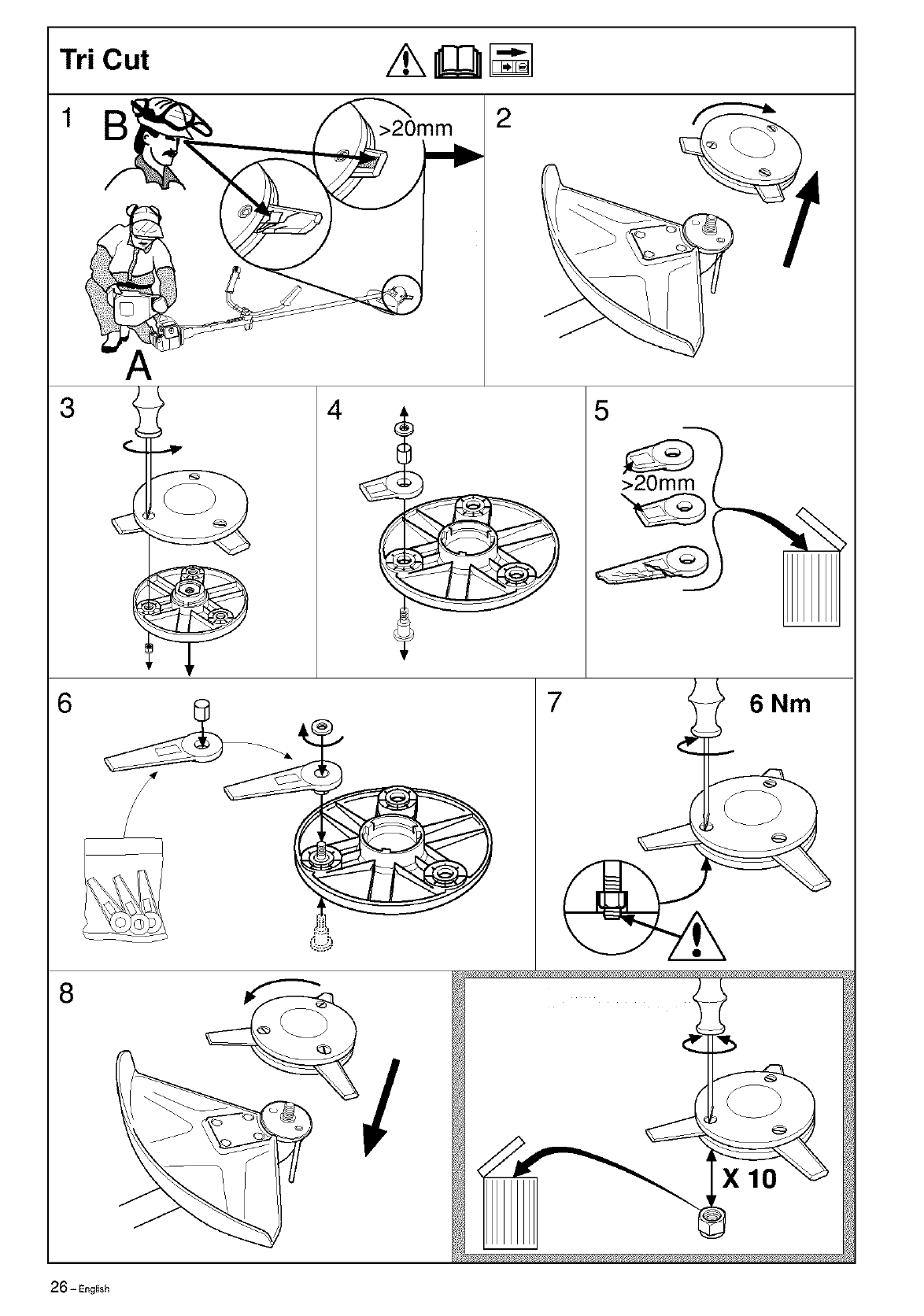
TriCut /_ _ I_1
12
3
6
8
r
!i_!,
)
7
6Nm
26- English
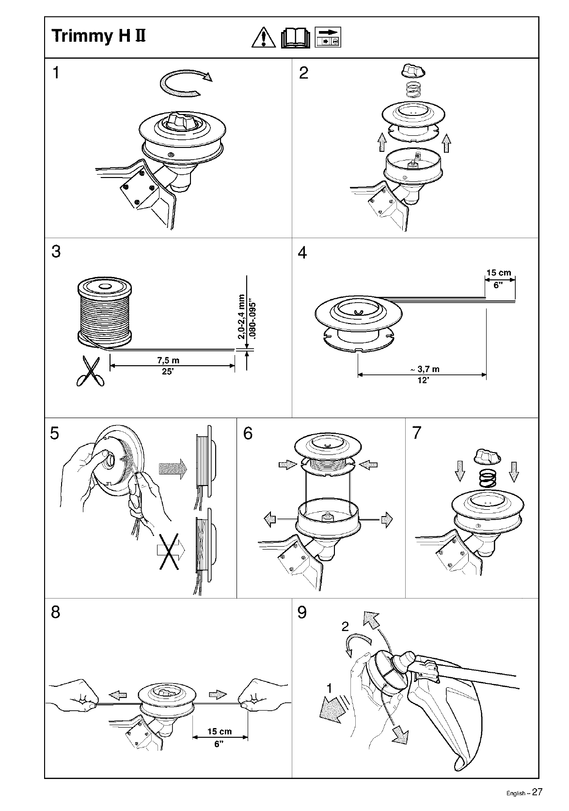
Trimmy H !1 z_ _
3
E
E_
,,Sm "1T
25'
4
~3,7 m
i12'
15 cm
5 6 7
8
15 cm
6"
9
E_l_sh-27
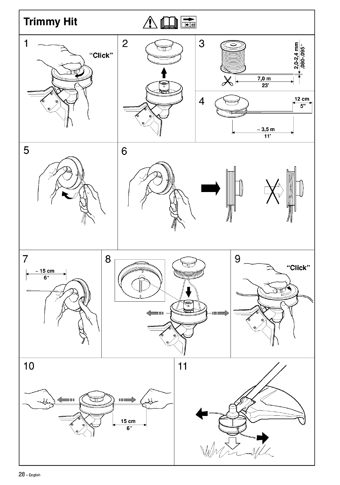
Trimmy Hit /_ _
3
1_Click"
_q
7,0m"1T
23'
5
)
6
4
~ 3,5 m
|I
11'
10 11
15 cm
6"
28 - Eng{ish
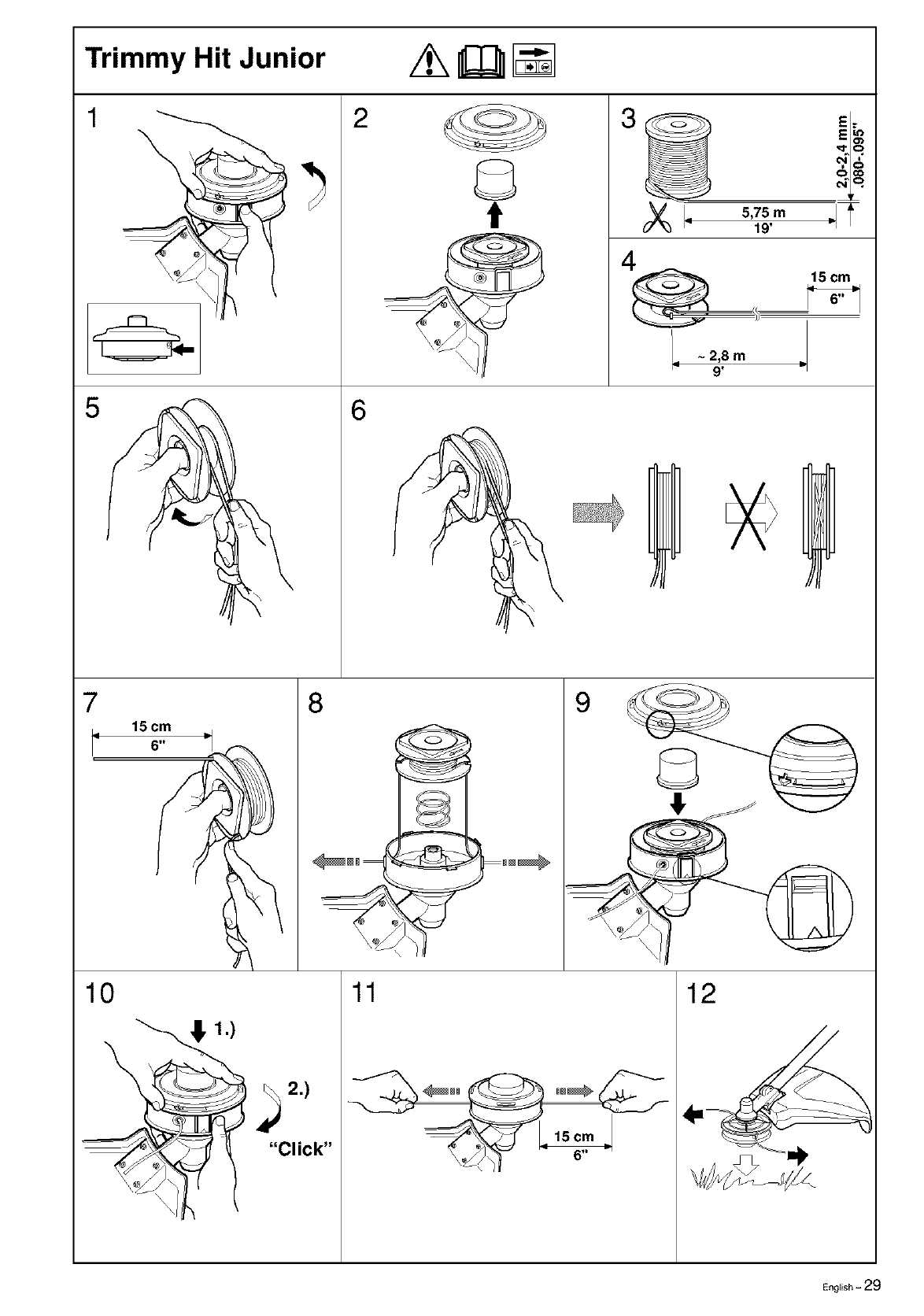
Trimmy Hit Junior z_ _ I_
1 2 3 E;
tr
5,75m IT
19'
15 cm
4
6
.- ~2,8 m =
9'
7
15 cm
6.' _J
10
8
11 12
__Y "Click"
English -29
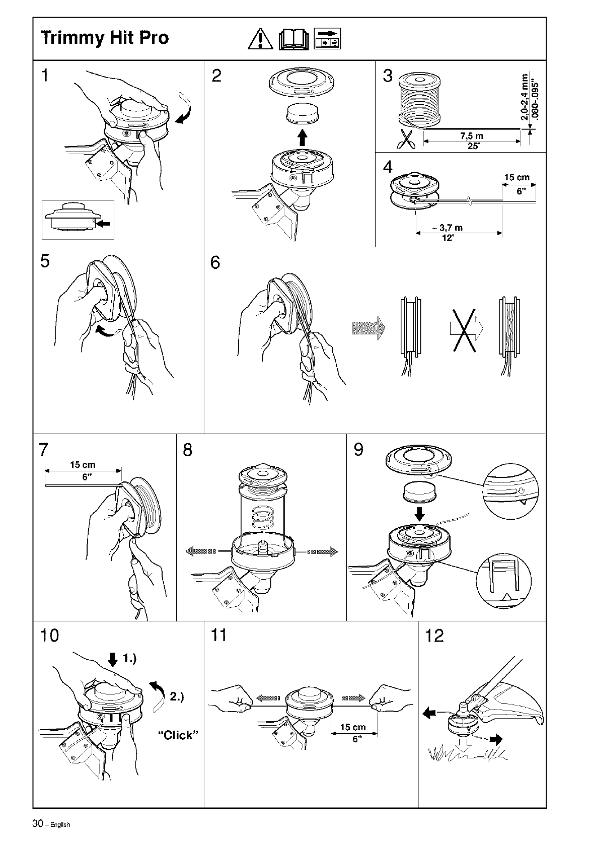
Trimmy Hit Pro //_ _I_
12 3
7,5m ,I
25'
t
4
6
= ~ 3,7 m
12'
15 cm
7
i_ 15cm =,
,\
10
8
11 12
30-Eng{ish
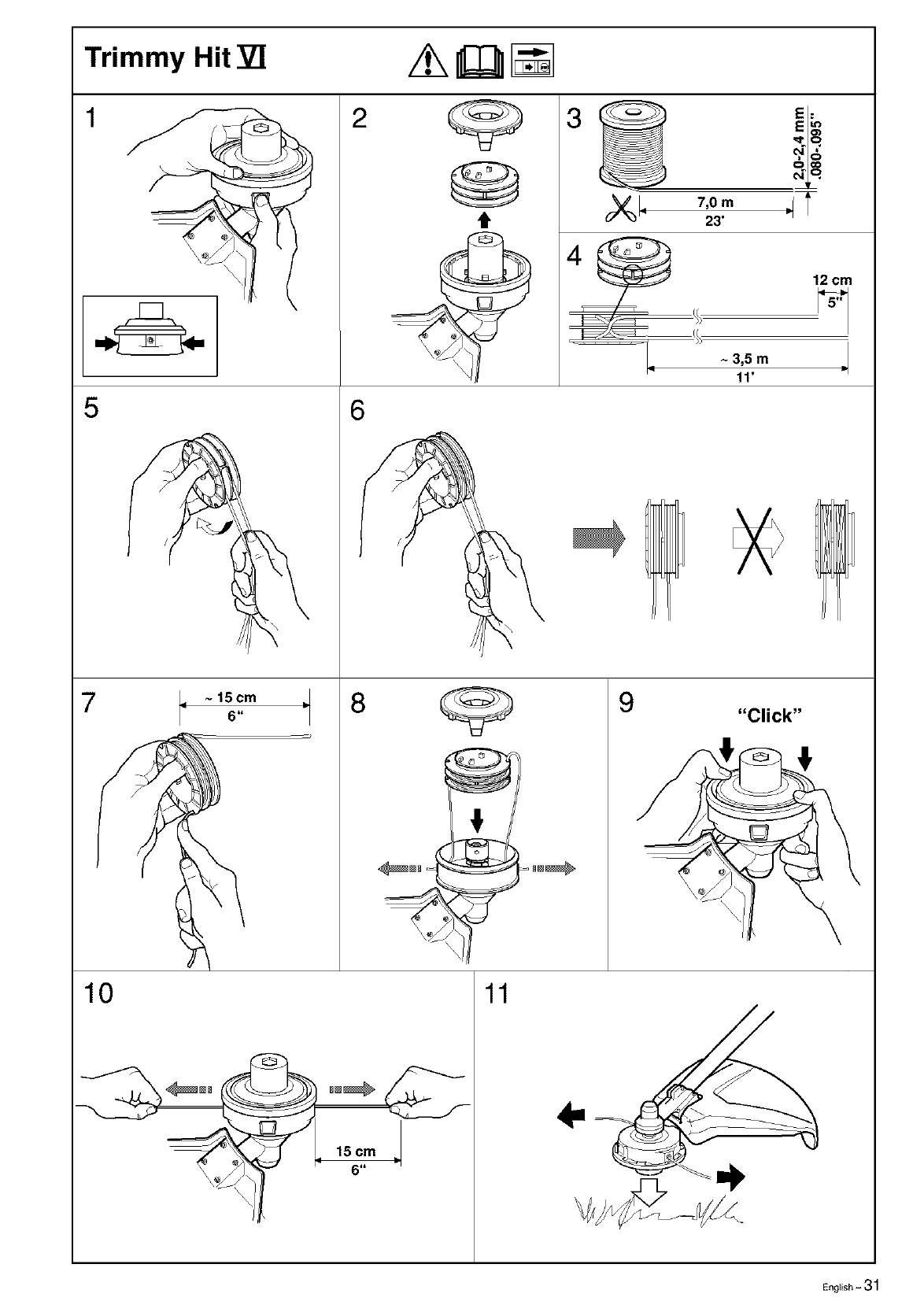
Trimmy Hit VI /_ _ []
2 3
5
7
/
= ~ 15cm
6
6
8
t
E:
E_
7,0 m _l '
I
23'
12 cm
lq
9
I
~3,5 m m.I
I
11'
"Click"
10
15 cm
6"
11
English -31
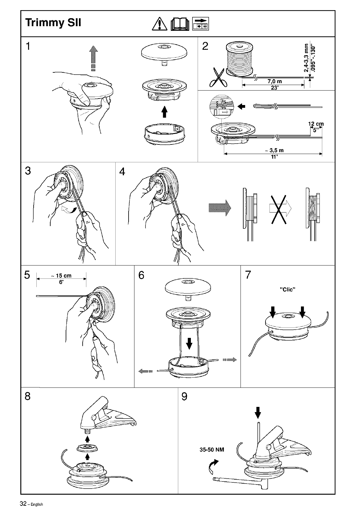
Trimmy SII /_ II[I]ll_
1
3
5
[]
t
7,0 m
23'
E6
Eo_
_6
olT
~3,5 m
11'
12 cm
\
~15cm
6'
I
\
4
6
_°°_
7
"Clic"
8
,I,
9
!
32 - English
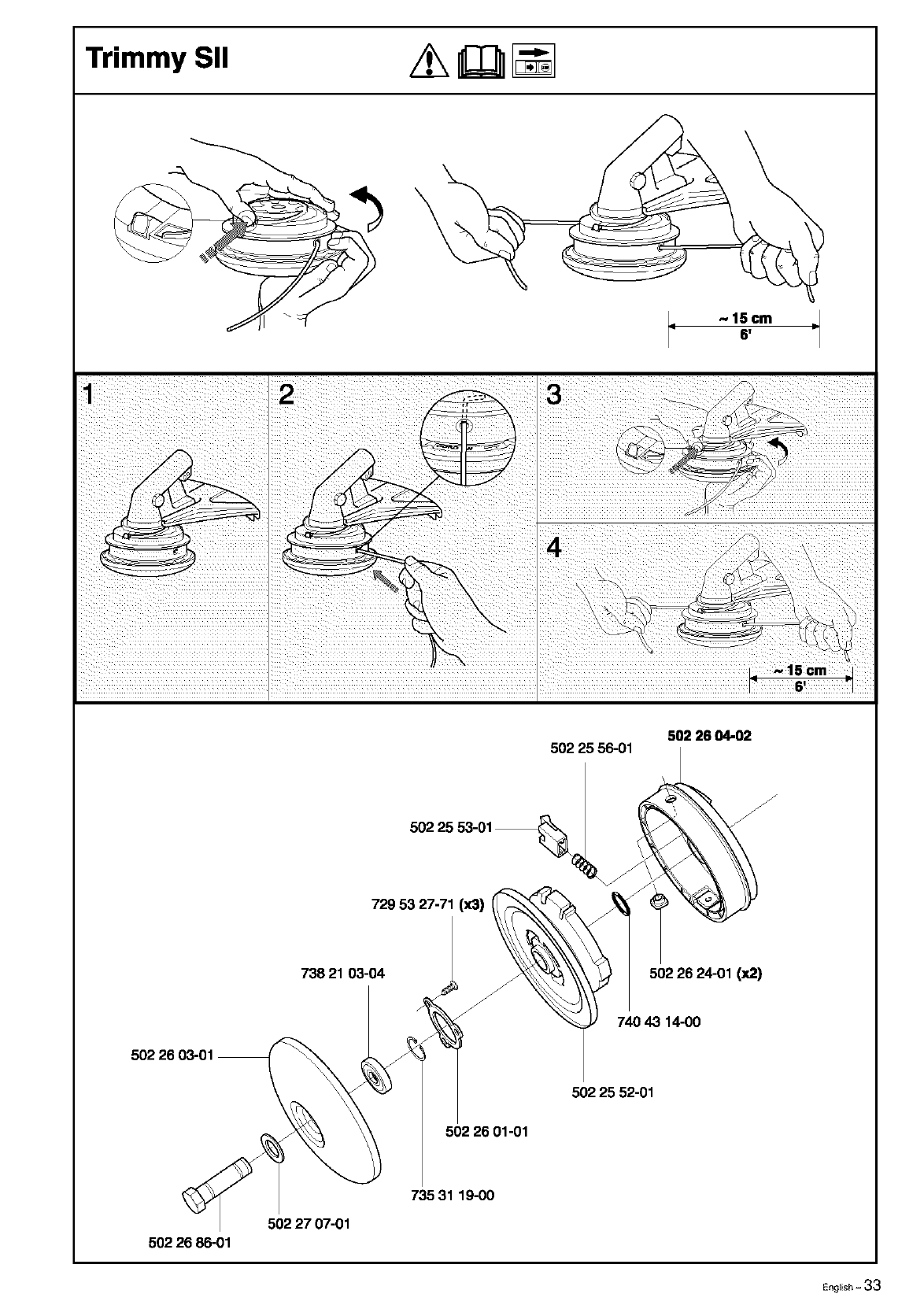
Trimmy Sll //_k_ [_
~15cm
98'
502 28 04-02
502 25 56-01
502 25 53-01 _ ;
oo oli°oo
502 26 03-01 _ _ 740 4314 O0
502 25 52-01
502 26 01-01
_,_ 73531 19-00
5022707-01
502 26 86-01
EngEish - 33
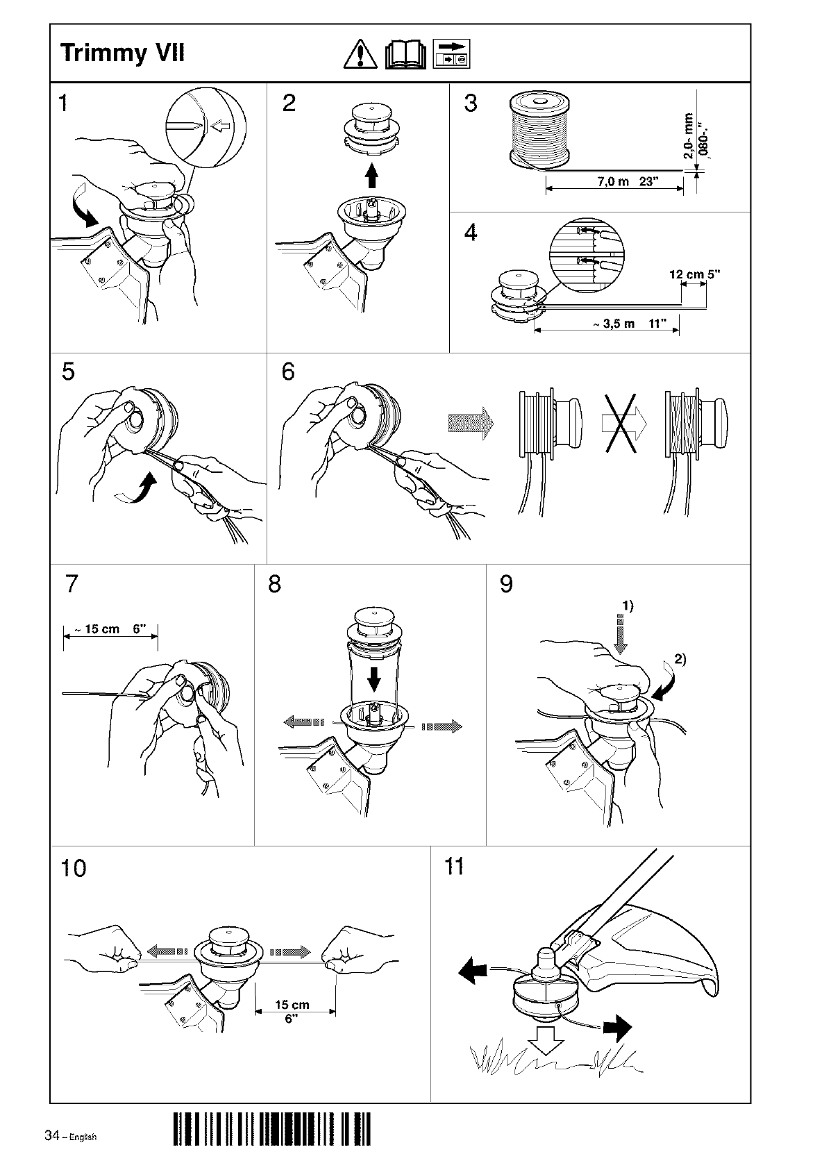
Trimmy VII /_k _
1 3
t
4
7,0 m 23"
.__ 3,5 m 12 cm 5"
11" '='1
5 6
7
1=~15cm 6"=1
8@9
1)
10
t5cm
I 6"
34__oo,,shIIIIIIIIIIIIIIIIIIIIIIII

English - 35

114 O0 98-95
IIIIIIIIIIIIIIIIIIIIIIII _oo_,,
