Husqvarna 917289600 User Manual TRACTOR Manuals And Guides 1006712L
User Manual: Husqvarna 917289600 917289600 HUSQVARNA TRACTOR - Manuals and Guides View the owners manual for your HUSQVARNA TRACTOR #917289600. Home:Lawn & Garden Parts:Husqvarna Parts:Husqvarna TRACTOR Manual
Open the PDF directly: View PDF ![]() .
.
Page Count: 56

®
m
Owner's Manual
532 43 62-86 Rev. 1
SAFETY RULES
Safe Operation Practices for Ride=On Mowers
DANGER: THiS CUTTING MACHINE iS CAPABLE OF AMPUTATING HANDS AND FEET AND THROWING OBJECTS. FAILURE
TO OBSERVE THE FOLLOWING SAFETY INSTRUCTIONS COULD RESULTIN SERIOUS iNJURY OR DEATH.
WARNING: in order to prevent acci=
dental starting when setting up, trans-
porting, adjusting or making repairs,
always disconnect spark plug wire
and place wire where it cannot contact
spark plug.
WARNING: Do not coast down ahill
in neutral, you may lose control of the
tractor.
WARNING: Tow only the attachments
that are recommended by and comply
with specifications of the manufacturer
of your tractor. Use common sense
when towing. Operate only at the low-
est possible speed when on aslope.
Too heavy of a load, while on a slope,
is dangerous. Tires can lose traction
with the ground and cause you to lose
control of your tractor.
WARNING
Engine exhaust, some of its constituents, and cer=
tain vehicle components contain or emit chemicals
known to the State of California to cause cancer and
birth defects or other reproductive harm.
•Do not operate machine without the entire grass catcher,
discharge chute, or other safety devices in place and
working.
•Slow down before turning.
•Never leave a running machine unattended. Always
turn off blades, set parking brake, stop engine, and
remove keys before dismounting.
•Disengage blades when not mowing. Shut off engine
and wait for all parts to come to a complete stop before
cleaning the machine, removing the grass catcher, or
unclogging the discharge chute.
•Operate machine only in daylight or good artificial
light.
•Do not operate the machine while under the influence
of alcohol or drugs.
•Watch for traffic when operating near or crossing
roadways.
•Use extra care when loading or unloading the machine
into a trailer or truck.
•Always wear eye protection when operating ma-
chine.
•Data indicates that operators, age 60 years and above,
are involved in a large percentage of riding mower-re-
lated injuries. These operators should evaluate their
ability to operate the riding mower safely enough to
protect themselves and others from serious injury.
•Follow the manufacturer's recommendation for wheel
weights or counterweights.
•Keep machine free of grass , leaves or other debris
build-up which can touch hot exhaust/engine parts and
burn. Do not allow the mower deck to plow leaves or
other debris which can cause build-up to occur. Clean
any oil or fuel spillage before operating or storing the
machine. Allow machine to cool before storage.
WARNING
Battery posts, terminals and related accessories
contain lead and lead compounds, chemicals known
to the State of California to cause cancer and birth
defects or other reproductive harm. Wash hands
after handling.
I. GENERAL OPERATION
•Read, understand, and follow all instructions on the
machine and in the manual before starting.
•Do not put hands or feet near rotating parts or under
the machine. Keep clear of the discharge opening at
all times.
•Only allow responsible adults, who are familiar with
the instructions, to operate the machine.
•Clear the area of objects such as rocks, toys, wire, etc.,
which could be picked up and thrown by the blades.
•Be sure the area is clear of bystanders before operat-
ing. Stop machine if anyone enters the area.
•Never carry passengers.
•Do not mow in reverse unless absolutely necessary.
Always look down and behind before and while backing.
•Never direct discharged material toward anyone. Avoid
discharging material against a wall or obstruction.
Material may ricochet back toward the operator. Stop
the blades when crossing gravel surfaces.
ft. SLOPE OPERATION
Slopes are a major factor related to loss of control and
tip-over accidents, which can result in severe injury or
death. Operation on all slopes requires extra caution. If
you cannot back up the slope or if you feel uneasy on it,
do not mow it.
•Mow up and down slopes, not across.
•Watch for holes, ruts, bumps, rocks, or other hidden
objects. Uneven terrain could overturn the machine.
Tall grass can hide obstacles.
•Choose a low ground speed so that you will not have
to stop or shift while on the slope.
•Do not mow on wet grass. Tires may lose traction.
Always keep the machine in gear when going down
slopes. Do not shift to neutral and coast downhill.
•Avoid starting, stopping, or turning on a slope. If the
tires lose traction, disengage the blades and proceed
slowly straight down the slope.
•Keep all movement on the slopes slow and gradual.
Do not make sudden changes in speed or direction,
which could cause the machine to roll over.
•Use extra care while operating machine with grass
catchers or other attachments; they can affect the
stability of the machine. Do no use on steep slopes.
•Do not try to stabilize the machine by putting your foot
on the ground.
•Do not mow near drop-offs, ditches, or embankments.
The machine could suddenly roll over if a wheel is over
the edge or if the edge caves in.
2
SAFETY RULES
Safe Operation Practices for Ride=On Mowers &
ill. CHILDREN
Tragic accidents can occur if the operator is not alert to
the presence of children. Children are often attracted to
the machine and the mowing activity. Never assume that
children will remain where you last saw them.
•Keep children out ofthe mowing area and inthe watchful
care of a responsible adult other than the operator.
Be alert and turn machine off if a child enters the
area.
• Before and while backing, look behind and down for
small children.
• Never carry children, even with the blades shut off. They
may fall off and be seriously injured or interfere with
safe machine operation. Children who have been given
rides in the past may suddenly appear in the mowing
area for another ride and be run over or backed over
by the machine.
• Never allow children to operate the machine.
• Use extra care when approaching blind corners, shrubs,
trees, or other objects that may block your view of a
child.
IV. TOWING
• Tow only with a machine that has a hitch designed for
towing. Do not attach towed equipment except at the
hitch point.
• Follow the manufacturer's recommendation for weight
limits for towed equipment and towing on slopes.
• Never allow children or others in or on towed equip-
ment.
• On slopes, the weight of the towed equipment may
cause loss of traction and loss of control.
• Travel slowly and allow extra distance to stop.
V. SAFE HANDLING OF GASOLINE
To avoid personal injury or property damage, use extreme
care in handling gasoline. Gasoline is extremely flammable
and the vapors are explosive.
• Extinguish all cigarettes, cigars, pipes, and other
sources of ignition.
• Use only approved gasoline container.
• Never remove gas cap or add fuel with the engine
running. Allow engine to cool before refueling.
• Never fuel the machine indoors.
• Never store the machine or fuel container where there
is an open flame, spark, or pilot light such as on a water
heater or other appliances.
• Never fill containers inside a vehicle or on a truck or
trailer bed with plastic liner. Always place containers
on the ground away from your vehicle when filling.
• Remove gas-powered equipment from the truck or
trailer and refuel it on the ground. If this is not possible,
then refuel such equipment with a portable container,
rather than from a gasoline dispenser nozzle.
• Keep the nozzle in contact with the rim of the fuel tank or
container opening at all times until fueling is complete.
Do not use a nozzle lock-open device.
• If fuel is spilled on clothing, change clothing immedi-
ately.
• Never overfill fuel tank. Replace gas cap and tighten
securely.
GENERAL
•Never operate machine in a closed area.
Keep all nuts and bolts tight to be sure the equipment
is in safe working condition.
Never tamper with safety devices. Check their proper
operation regularly.
Keep machine free of grass, leaves, or other debris
build-up. Clean oil or fuel spillage and remove any fuel-
soaked debris. Allow machine to cool before storing.
If you strike a foreign object, stop and inspect the
machine. Repair, if necessary, before restarting.
Never make any adjustments or repairs with the engine
running.
Check grass catcher components and the discharge
chute frequently and replace with manufacturer's rec-
ommended parts, when necessary.
Mower blades are sharp. Wrap the blade or wear
gloves, and use extra caution when servicing them.
Check brake operation frequently. Adjust and service
as required.
Maintain or replace safety and instruction labels, as
necessary.
e
e
e
e
e
e
e
e
e
Be sure the area is clear of bystanders before operat-
ing. Stop machine if anyone enters the area.
Never carry passengers.
Do not mow in reverse unless absolutely necessary.
Always look down and behind before and while back-
ing.
Never carry children, even with the blades shut off. They
may fall off and be seriously injured or interfere with
safe machine operation. Children who have been given
rides in the past may suddenly appear in the mowing
area for another ride and be run over or backed over
by the machine.
Keep children out ofthe mowing area and in the watchful
care of a responsible adult other than the operator.
Be alert and turn machine off if a child enters the
area.
Before and while backing, look behind and down for
small children.
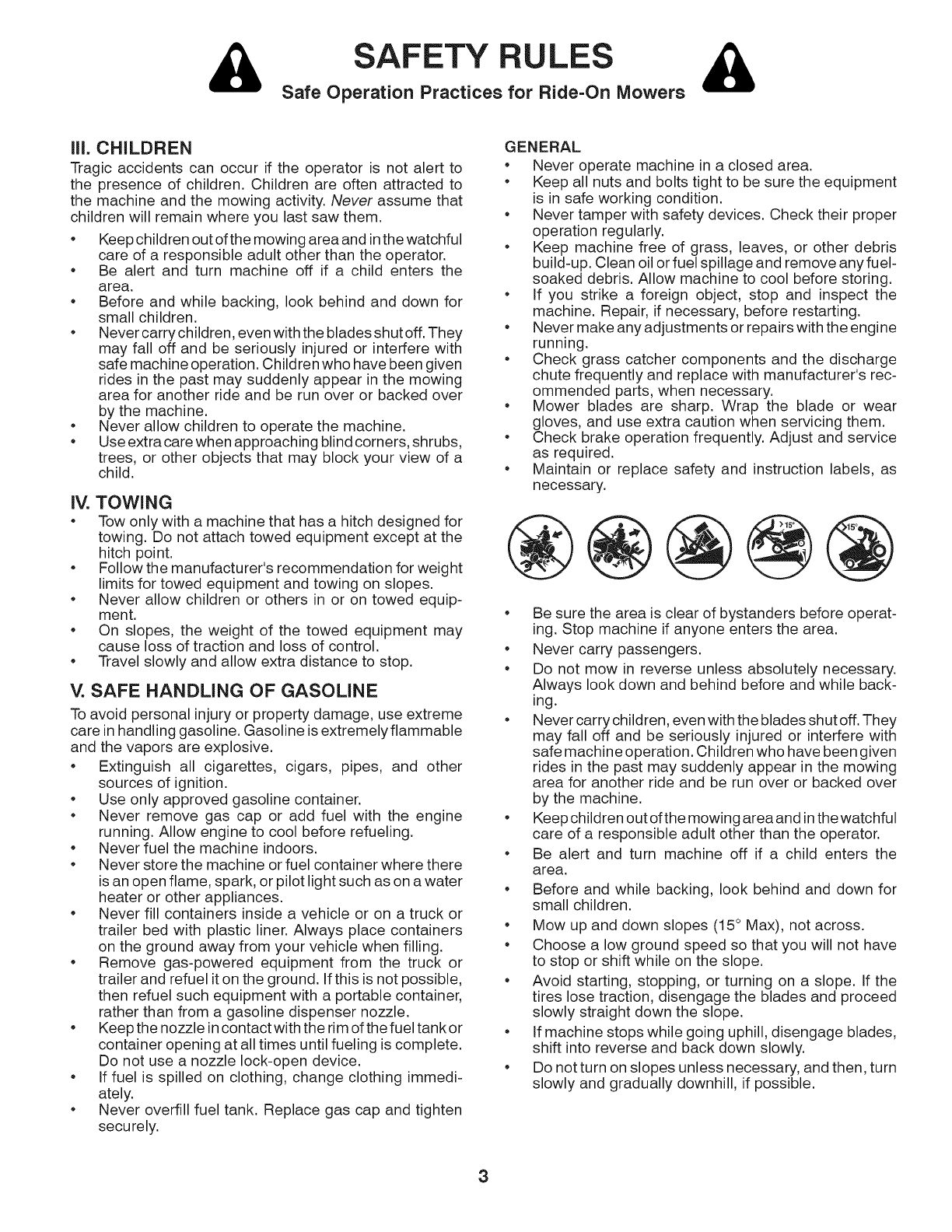
Mow up and down slopes (15° Max), not across.
Choose a low ground speed so that you will not have
to stop or shift while on the slope.
Avoid starting, stopping, or turning on a slope. If the
tires lose traction, disengage the blades and proceed
slowly straight down the slope.
If machine stops while going uphill, disengage blades,
shift into reverse and back down slowly.
Do not turn on slopes unless necessary, and then, turn
slowly and gradually downhill, if possible.
3
PRODUCT SPECiFiCATiONS
Gasoline Capacity 1.5 Gallons
and Type: Unleaded Regular
Oil Type (API-SG-SL): SAE 30 (above 32°F)
SAE 5W-30 (below 32°F)
Oil Capacity: 48 oz.
Spark Plug: Champion RC12YC
(Gap: .030")
Ground Speed (MPH): Forward: 0 - 5.2
Reverse: 0 - 2.9
Charging System: 3 AMPS Battery
5 AMPS Headlight
Battery: AMP/HR: 28
Min. CCA: 230
Case Size: U1R
Blade Bolt Torque: 45-55 Ft. Lbs.
CUSTOMER RESPONSIBILITIES
• Read and observe the safety rules.
• Follow a regular schedule in maintaining, caring for
and using your tractor.
• Follow the instructions under "Maintenace" and "Stor-
age" sections of this owner's manual.
WARNING: This tractor is equipped with an internal com-
bustion engine and should not be used on or near any un-
improved forest-covered, brush-covered or grass-covered
land unless the engine's exhaust system is equipped with
a spark arrester meeting applicable local or state laws (if
any). If a spark arrester is used, it should be maintained
in effective working order by the operator.
In the state of California the above is required by law
(Section 4442 of the California Public Resources Code).
Other states may have similar laws. Federal laws apply
on federal lands.
CONGRATULATIONS on your purchase of a new tractor. It
has been designed, engineered and manufactured to give
you the best possible dependability and performance.
Should you experience any problem you cannot easily rem-
edy, please contact your nearest authorized service center/
department. We have competent, well-trained technicians
and the proper tools to service or repair this tractor.
Please read and retain this manual. The instructions will
enable you to assemble and maintain your tractor properly.
Always observe the "SAFETY RULES".
TABLE OF CONTENTS
SAFETY RULES ......................................................... 2=3
PRODUCT SPECIFICATIONS ....................................... 4
CUSTOMER RESPONSIBILITIES ................................. 4
ASSEMBLY ................................................................. 6-8
OPERATION ........................................................... 10-14
MAINTENANCE SCHEDULE ...................................... 15
MAINTENANCE ...................................................... 15-18
SERVICE AND ADJUSTMENTS ............................ 19=24
STORAGE .................................................................... 25
TROUBLESHOOTING ............................................ 26=27
REPAIR PARTS ...................................................... 28=49
4

UNASSEMBLED PARTS
Steering Wheel
1 / *_
I
Steering
Wheel Insert Steering
Wheel
tt _ x
|i/
i i t
Steering Wheel ""J--"
Adapter Steering Boot
(1) Large
Flat Washer
(1) Hex Bolt
Steering
Extension
Shaft
(1) Lock
Washer
Seat
(1) Washer
(1) Seat (1) Bolt
Key(s)
(1) Oil Drain Tube
For Future Use
Slope Sheet
5
ASSEMBLY
Your new tractor has been assembled at the factory with exception of those parts left unassembled for shipping purposes.
To ensure safe and proper operation of your tractor all parts and hardware you assemble must be tightened securely. Use
the correct tools as necessary to ensure proper tightness.
TOOLS REQUIRED FOR ASSEMBLY
A socket wrench set will make assembly easier. Standard
wrench sizes are listed.
(1) 5/16" wrench Utility knife
(2) 7/16" wrenches Tire pressure gauge
(2) 1/2" wrenches Pliers
(1) 9/16" wrench
When right or left hand is mentioned in this manual, it means
when you are in the operating position (seated behind the
steering wheel).
TO REMOVE TRACTOR FROM CARTON
UNPACK CARTON
• Remove all accessible loose parts and parts cartons
from carton.
• Cut along dotted lines on all four panels of carton.
Remove end panels and lay side panels flat.
• Check for any additional loose parts or cartons and
remove.
BEFORE REMOVING TRACTOR FROM
SKID
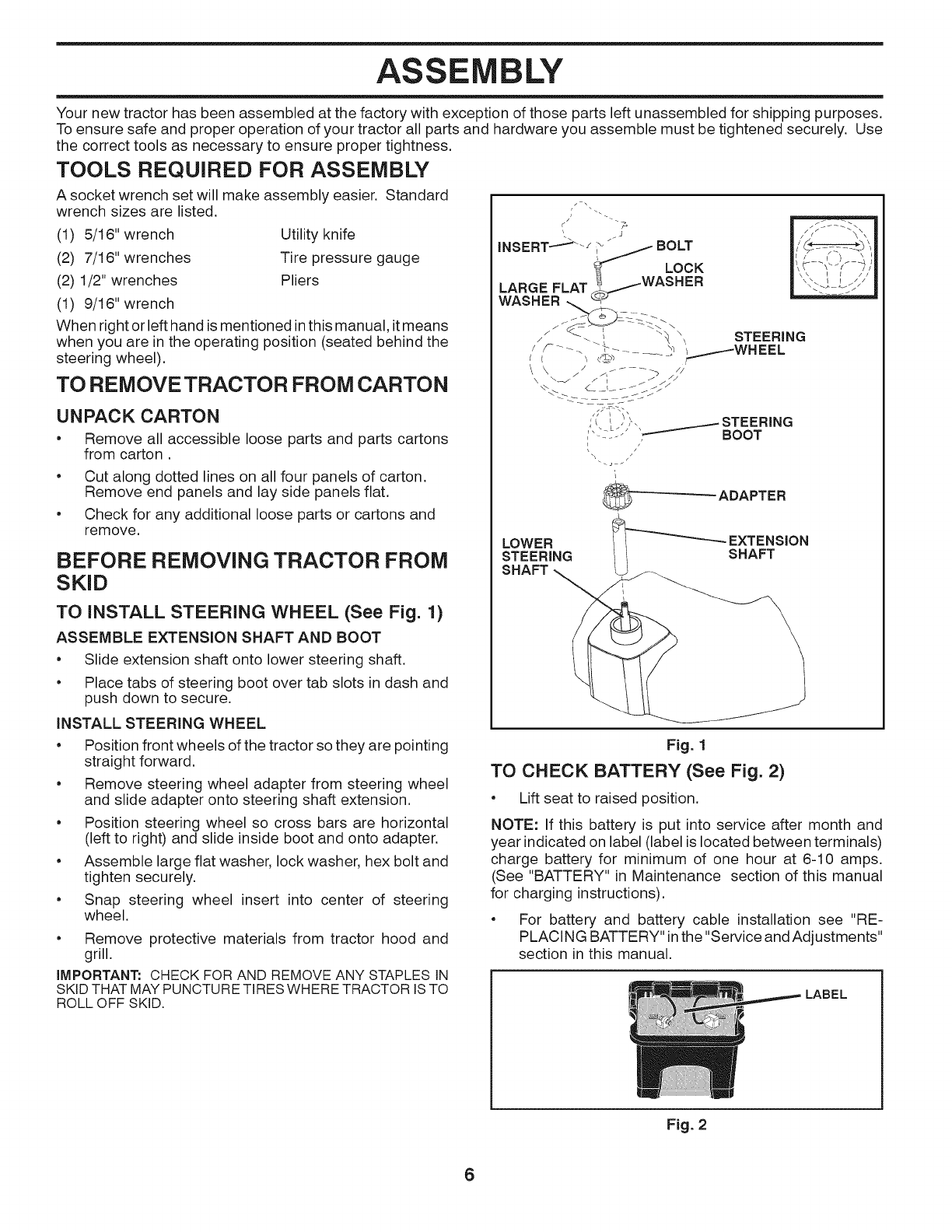
TO INSTALL STEERING WHEEL (See Fig. 1)
ASSEMBLE EXTENSION SHAFT AND BOOT
• Slide extension shaft onto lower steering shaft.
• Place tabs of steering boot over tab slots in dash and
push down to secure.
INSTALL STEERING WHEEL
/"'- 7° .;f:--2-_
/\
?J -BOLT !,',
LARGE FLAT WASHER " ' '"
WASHERJ
zi" _\x STEERING
tF - _; x _WHEEL
t_
_--_ STEERING
BOOT
\/
ADAPTER
LOWER EXTENSION
STEERING SHAFT
SHAFT _ -
• Position front wheels of the tractor so they are pointing
straight forward.
• Remove steering wheel adapter from steering wheel
and slide adapter onto steering shaft extension.
Fig. 1
TO CHECK BATTERY (See Fig. 2)
Lift seat to raised position.
Position steering wheel so cross bars are horizontal
(left to right) and slide inside boot and onto adapter.
• Assemble large flat washer, lock washer, hex bolt and
tighten securely.
• Snap steering wheel insert into center of steering
wheel.
• Remove protective materials from tractor hood and
grill.
iMPORTANT: CHECK FOR AND REMOVE ANY STAPLES IN
SKID THAT MAY PUNCTURE TIRES WHERE TRACTOR IS TO
ROLL OFF SKID.
NOTE: If this battery is put into service after month and
year indicated on label (label is located between terminals)
charge battery for minimum of one hour at 6-10 amps.
(See "BATTERY" in Maintenance section of this manual
for charging instructions).
• For battery and battery cable installation see "RE-
PLACING BATTERY" inthe "Service and Adjustments"
section in this manual.
LABEL
Fig. 2
6
ASSEMBLY
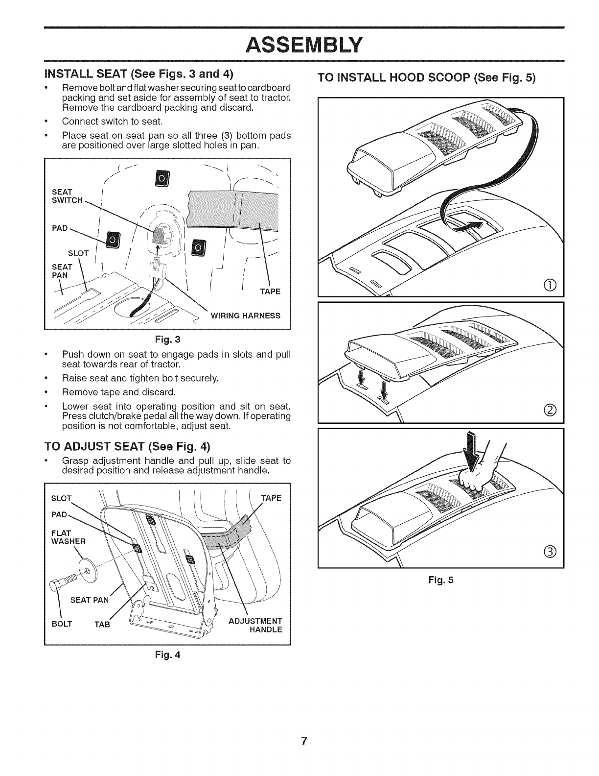
iNSTALL SEAT (See Figs. 3 and 4)
* Remove bolt and flat washer securing seat to cardboard
packing and set aside for assembly of seat to tractor.
Remove the cardboard packing and discard.
* Connect switch to seat.
Place seat on seat pan so all three (3) bottom pads
are positioned over large slotted holes in pan.
TO INSTALL HOOD SCOOP (See Fig. 5)
/
/
SEAT /
SWITCH
PAD _
SLOT /
7_
t
ITAPE
WIRING HARNESS
Fig. 3
Push down on seat to engage pads in slots and pull
seat towards rear of tractor.
• Raise seat and tighten bolt securely.
• Remove tape and discard.
• Lower seat into operating position and sit on seat.
Press clutch/brake pedal all the way down. If operating
position is not comfortable, adjust seat.
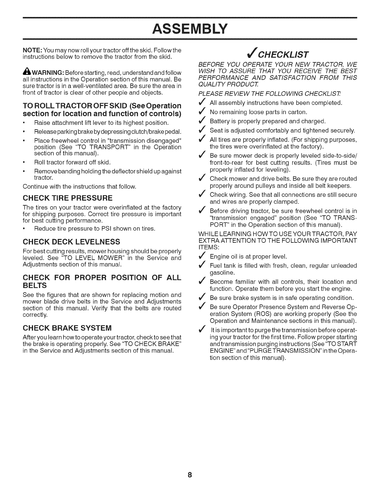
TO ADJUST SEAT (See Fig. 4)
• Grasp adjustment handle and pull up, slide seat to
desired position and release adjustment handle.
SLOT TAPE
FLAT
WASHER
SEAT PAN
BOLT TAB ADJUSTMENT
HANDLE
Fig. 5
®
®
Fig. 4
7
ASSEMBLY
NOTE: You may now roll your tractor off the skid. Follow the
instructions below to remove the tractor from the skid.
_iL.WARNING: Before starting, read, understand and follow
all instructions in the Operation section of this manual. Be
sure tractor is in a well-ventilated area. Be sure the area in
front of tractor is clear of other people and objects.
TO ROLLTRACTOR OFF SKiD (See Operation
section for location and function of controls)
•Raise attachment lift lever to its highest position.
• Release parking brake by depressing clutch/brake pedal.
• Place freewheel control in "transmission disengaged"
position (See "TO TRANSPORT" in the Operation
section of this manual).
• Roll tractor forward off skid.
• Remove banding holding the deflector shield up against
tractor.
Continue with the instructions that follow.
CHECK TiRE PRESSURE
The tires on your tractor were overinflated at the factory
for shipping purposes. Correct tire pressure is important
for best cutting performance.
• Reduce tire pressure to PSI shown on tires.
CHECK DECK LEVELNESS
For best cutting results, mower housing should be properly
leveled. See "TO LEVEL MOWER" in the Service and
Adjustments section of this manual.
CHECK FOR PROPER POSITION OF ALL
BELTS
See the figures that are shown for replacing motion and
mower blade drive belts in the Service and Adjustments
section of this manual. Verify that the belts are routed
correctly.
CHECK BRAKE SYSTEM
After you learn how to operate your tractor, check to see that
the brake is operating properly. See "TO CHECK BRAKE"
in the Service and Adjustments section of this manual.
J'CHECKLIST
BEFORE YOU OPERATE YOUR NEW TRACTOR, WE
WISH TO ASSURE THAT YOU RECEIVE THE BEST
PERFORMANCE AND SATISFACTION FROM THIS
QUALITY PRODUCT.
PLEASE REVIEW THE FOLLOWING CHECKLIST7
J" All assembly instructions have been completed.
J" No remaining loose parts in carton.
J" Battery is properly prepared and charged.
J" Seat is adjusted comfortably and tightened securely.
J" All tires are properly inflated. (For shipping purposes,
the tires were overinflated at the factory).
J" Be sure mower deck is properly leveled side-to-side/
front-to-rear for best cutting results. (Tires must be
properly inflated for leveling).
J" Check mower and drive belts. Be sure they are routed
properly around pulleys and inside all belt keepers.
J" Check wiring. See that all connections are still secure
and wires are properly clamped.
J" Before driving tractor, be sure freewheel control is in
"transmission engaged" position (See "TO TRANS-
PORT" in the Operation section of this manual).
WHILE LEARNING HOWTO USE YOUR TRACTOR, PAY
EXTRA ATTENTION TO THE FOLLOWING IMPORTANT
ITEMS:
J" Engine oil is at proper level.
J" Fuel tank is filled with fresh, clean, regular unleaded
gasoline.
J" Become familiar with all controls, their location and
function. Operate them before you start the engine.
J" Be sure brake system is in safe operating condition.
J" Be sure Operator Presence System and Reverse Op-
eration System (ROS) are working properly (See the
Operation and Maintenance sections in this manual).
J" It is important to purge the transmission before operat-
ing your tractor for the first time. Follow proper starting
andtransmission purging instructions (See "TO START
ENGINE" and"PURGE TRANSMISSION" inthe Opera-
tion section of this manual).
8

OPERATION
These symbols may appear on your tractor or in literature supplied with the product. Learn and understand their meaning.
LI",1 'e -Ib
CHOKE FAST SLOWREVERSE NEUTRAL HiGH LOW
ENGINE OFF REVERSE ENGINE ON ENGINE START PARKING BRAKE MOWER HEIGHT
OPERATION
SYSTEM (ROS)
LIGHTS ON FUEL BATTERY REVERSE FORWARD CRUISE CONTROL
IGNiTiON SWITCH
MOWER LiFT
CLUTCH/BRAKE
PEDAL
ATTACHMENT
CLUTCH DISENGAGED ATTACHMENT
CLUTCH ENGAGED
FREE WHEEL
(Automatic Models only)
DANGER, KEEP HANDS
AND FEET AWAY KEEP AREA CLEAR SLOPE HAZARDS
(SEE SAFETY RULES SECTION)
Failure to follow instructions
could result in serious injury or
death. The safety alert symbol
is used to identify safety inform-
ation about hazards which can
result in death, serious injury
and/or property damage.
A
A
A
DANGER indicates a hazard which, if not avoided,
will result in death or serious injury.
WARNING indicates a hazard which, if not avoided,
could result in death or serious injury.
CAUTION indicates a hazard which, if not avoided,
might result in minor or moderate injury.
CAUTION when used without the alert symbol,
indicates a situation that could result in damage
to the tractor and/or engine.
HOT SURFACES indicates a hazard which,
if not avoided, could result in death, serious injury
and/or property damage.
FIRE indicates a hazard which, if not avoided,
could result in death, serious injury and/or
property damage.
9
OPERATION
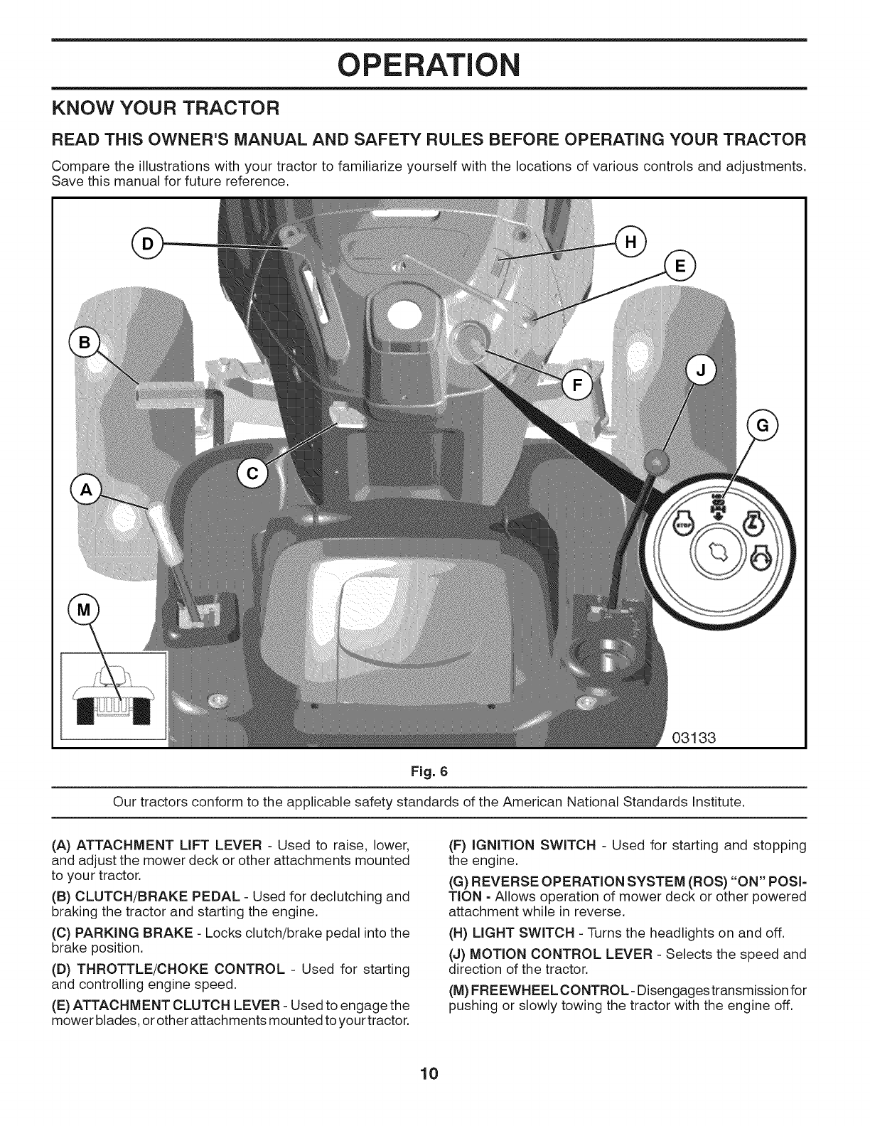
KNOW YOUR TRACTOR
READ THiS OWNER'S MANUAL AND SAFETY RULES BEFORE OPERATING YOUR TRACTOR
Compare the illustrationswith your tractor to familiarize yourself with the locations of various controls and adjustments.
Save this manual for future reference.
03133
Fig. 6
Our tractors conform to the applicable safety standards of the American National Standards Institute.
(A) ATTACHMENT LIFT LEVER - Used to raise, lower,
and adjust the mower deck or other attachments mounted
to your tractor.
(B) CLUTCH/BRAKE PEDAL - Used for declutching and
braking the tractor and starting the engine.
(C) PARKING BRAKE - Locks clutch/brake pedal into the
brake position.
(D) THROTTLE/CHOKE CONTROL - Used for starting
and controlling engine speed.
(E) ATTACHMENT CLUTCH LEVER - Used to engage the
mower blades, or other attachments mounted to your tractor.
(F) IGNITION SWITCH - Used for starting and stopping
the engine.
(G) REVERSE OPERATION SYSTEM (ROS) "ON" POSI=
TION =Allows operation of mower deck or other powered
attachment while in reverse.
(H) LIGHT SWITCH - Turns the headlights on and off.
(J) MOTION CONTROL LEVER - Selects the speed and
direction of the tractor.
(M) FREEWHEEL CONTROL- Disengages transmission for
pushing or slowly towing the tractor with the engine off.
10
OPERATION
The operation of any tractor can result in foreign objects thrown into the eyes, which can result
in severe eye damage. Always wear safety glasses or eye shields while operating your tractor or
performing any adjustments or repairs. We recommend awide vision safety mask over spectacles
or standard safety glasses.
HOW TO USE YOUR TRACTOR
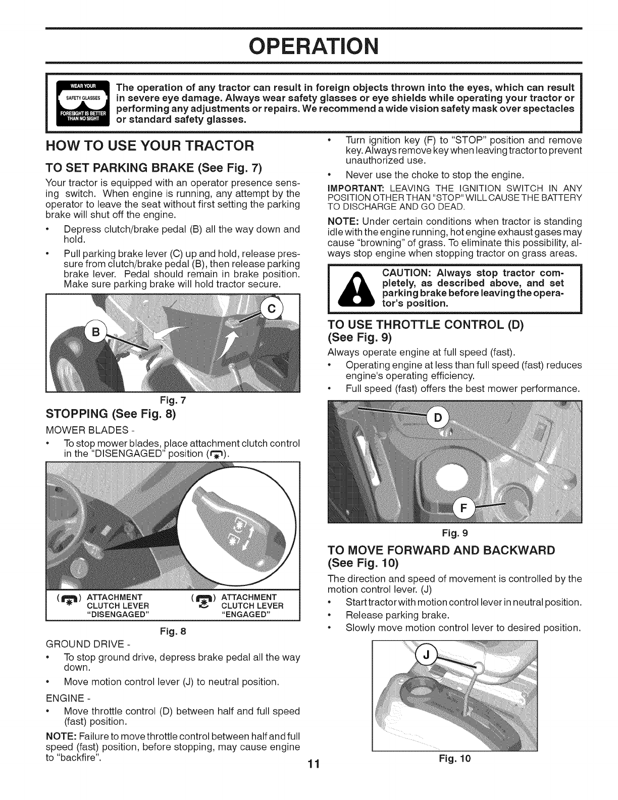
TO SET PARKING BRAKE (See Fig. 7)
Your tractor is equipped with an operator presence sens-
ing switch. When engine is running, any attempt by the
operator to leave the seat without first setting the parking
brake will shut off the engine.
•Depress clutch/brake pedal (B) all the way down and
hold.
Pull parking brake lever (C) up and hold, release pres-
sure from clutch/brake pedal (B), then release parking
brake lever. Pedal should remain in brake position.
Make sure parking brake will hold tractor secure.
•Turn ignition key (F) to "STOP" position and remove
key. Always remove key when leaving tractor to prevent
unauthorized use.
•Never use the choke to stop the engine.
IMPORTANT: LEAVING THE IGNITION SWITCH IN ANY
POSITION OTHER THAN "STOP" WILL CAUSE THE BATTERY
TO DISCHARGE AND GO DEAD.
NOTE: Under certain conditions when tractor is standing
idle with the engine running, hot engine exhaust gases may
cause "browning" of grass. To eliminate this possibility, al-
ways stop engine when stopping tractor on grass areas.
_I CAUTION: Always stop tractor corn=
pleteiy, as described above, and set
parking brake before leaving the opera=
tot's position.
TO USE THROTTLE CONTROL (D)
(See Fig. 9)
Always operate engine at full speed (fast).
•Operating engine at less than full speed (fast) reduces
engine's operating efficiency.
•Full speed (fast) offers the best mower performance.
Fig. 7
STOPPING (See Fig. 8)
MOWER BLADES -
•To stop mower blades, place attachment clutch control
in the "DISENGAGED" position (r_).
(l_ll) ATTACHMENT (ll_) ATTACHMENT
CLUTCH LEVER CLUTCH LEVER
"DISENGAGED .... ENGAGED"
Fig. 8
GROUND DRIVE -
•To stop ground drive, depress brake pedal all the way
down.
•Move motion control lever (J) to neutral position.
ENGINE -
•Move throttle control (D) between half and full speed
(fast) position.
NOTE: Failure to move throttle control between half and full
speed (fast) position, before stopping, may cause engine
to "backfi re".
Fig. 9
TO MOVE FORWARD AND BACKWARD
(See Fig. 10)
The direction and speed of movement is controlled by the
motion control lever. (J)
•Start tractor with motion control lever in neutral position.
•Release parking brake.
•Slowly move motion control lever to desired position.
1 1 Fig. 10
OPERATION
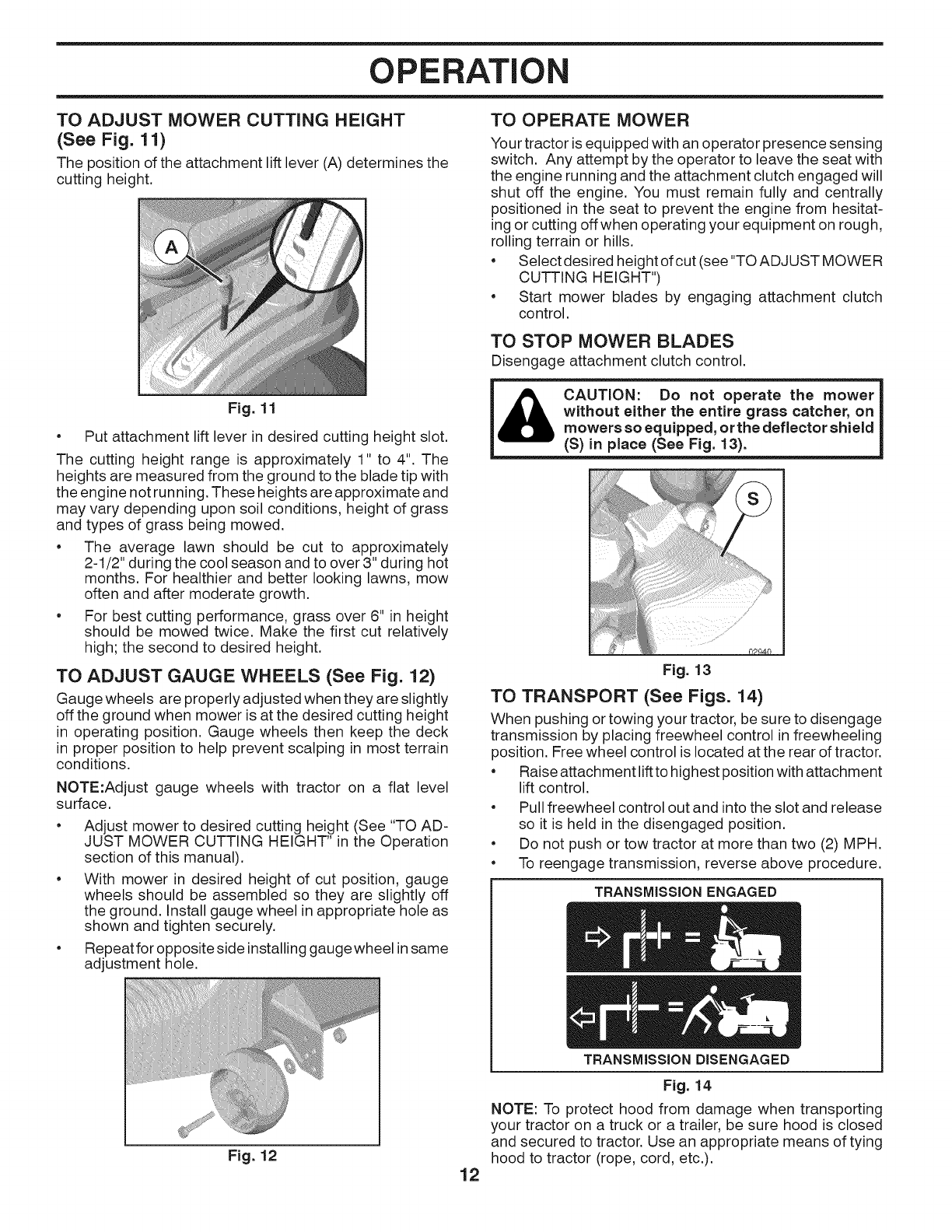
TO ADJUST MOWER CUTTING HEIGHT
(See Fig. 11)
The position of the attachment lift lever (A) determines the
cutting height.
Fig. 11
• Put attachment lift lever in desired cutting height slot.
The cutting height range is approximately 1" to 4". The
heights are measured from the ground to the blade tip with
the engine not running. These heights are approximate and
may vary depending upon soil conditions, height of grass
and types of grass being mowed.
• The average lawn should be cut to approximately
2-1/2" during the cool season and to over 3" during hot
months. For healthier and better looking lawns, mow
often and after moderate growth.
• For best cutting performance, grass over 6" in height
should be mowed twice. Make the first cut relatively
high; the second to desired height.
TO ADJUST GAUGE WHEELS (See Fig. 12)
Gauge wheels are properly adjusted when they are slightly
off the ground when mower is at the desired cutting height
in operating position. Gauge wheels then keep the deck
in proper position to help prevent scalping in most terrain
conditions.
NOTE:Adjust gauge wheels with tractor on a flat level
surface.
• Adjust mower to desired cutting height (See "TO AD-
JUST MOWER CUTTING HEIGHT" in the Operation
section of this manual).
• With mower in desired height of cut position, gauge
wheels should be assembled so they are slightly off
the ground. Install gauge wheel in appropriate hole as
shown and tighten securely.
• Repeat for opposite side installing gauge wheel in same
adjustment hole.
Fig. 12
TO OPERATE MOWER
Your tractor is equipped with an operator presence sensing
switch. Any attempt by the operator to leave the seat with
the engine running and the attachment clutch engaged will
shut off the engine. You must remain fully and centrally
positioned in the seat to prevent the engine from hesitat-
ing or cutting off when operating your equipment on rough,
rolling terrain or hills.
• Select desired height of cut (see"TO ADJUST MOWER
CUTTING HEIGHT")
• Start mower blades by engaging attachment clutch
control.
TO STOP MOWER BLADES
Disengage attachment clutch control.
CAUTION: Do not operate the mower
without either the entire grass catcher, on
mowers so equipped, orthe deflector shield
(S) in place (See Fig. 13).
12
Fig. 13
TO TRANSPORT (See Figs. 14)
When pushing or towing your tractor, be sure to disengage
transmission by placing freewheel control in freewheeling
position. Free wheel control is located at the rear of tractor.
• Raise attachment liftto highest position with attachment
lift control.
• Pull freewheel control out and intothe slot and release
so it is held in the disengaged position.
• Do not push or tow tractor at more than two (2) MPH.
• To reengage transmission, reverse above procedure.
TRANSMiSSiON ENGAGED
TRANSMiSSiON DISENGAGED
Fig. 14
NOTE: To protect hood from damage when transporting
your tractor on a truck or a trailer, be sure hood is closed
and secured to tractor. Use an appropriate means of tying
hood to tractor (rope, cord, etc.).
OPERATION
TOWING CARTS & OTHER ATTACHMENTS
Tow only the attachments that are recommended by and
comply with specifications of the manufacturer of your trac-
tor. Use common sense when towing. Too heavy of a load,
while on a slope, is dangerous. Tires can lose traction with
the ground and cause you to lose control of your tractor.
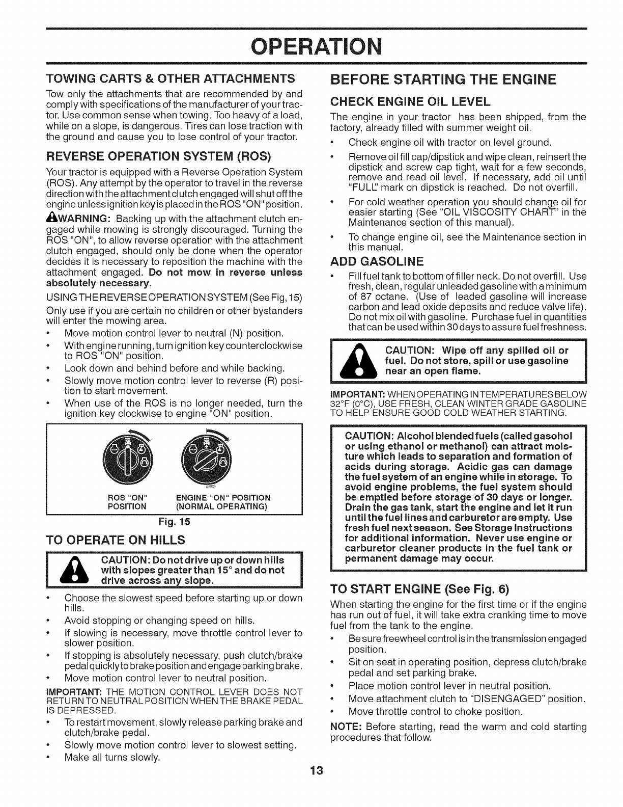
REVERSE OPERATION SYSTEM (ROS)
Your tractor is equipped with a Reverse Operation System
(ROS). Any attempt by the operator to travel in the reverse
direction with the attachment clutch engaged will shut offthe
engine unless ignition key is placed inthe ROS "ON" position.
,di_,WARNING: Backing up with the attachment clutch en-
gaged while mowing is strongly discouraged. Turning the
ROS "ON", to allow reverse operation with the attachment
clutch engaged, should only be done when the operator
decides it is necessary to reposition the machine with the
attachment engaged. Do not mow in reverse unless
absolutely necessary.
USING THE REVERSE OPERATION SYSTEM (See Fig, 15)
Only use if you are certain no children or other bystanders
will enter the mowing area.
• Move motion control lever to neutral (N) position.
• With engine running, turn ignition key counterclockwise
to ROS "ON" position.
• Look down and behind before and while backing.
• Slowly move motion control lever to reverse (R) posi-
tion to start movement.
•When use of the ROS is no longer needed, turn the
ignition key clockwise to engine "ON" position.
ROS "ON" ENGINE "ON" POSITION
POSITION (NORMAL OPERATING)
Fig. 15
TO OPERATE ON HILLS
iA c o ,o.;oooo,1
with slopes greater than 15° and do not
drive across any slope.
• Choose the slowest speed before starting up or down
hills.
• Avoid stopping or changing speed on hills.
• If slowing is necessary, move throttle control lever to
slower position.
• If stopping is absolutely necessary, push clutch/brake
pedal quicklyto brake position and engage parking brake.
• Move motion control lever to neutral position.
iMPORTANT: THE MOTION CONTROL LEVER DOES NOT
RETURN TO NEUTRAL POSITIONWHEN THE BRAKE PEDAL
IS DEPRESSED.
• To restart movement, slowly release parking brake and
clutch/brake pedal.
• Slowly move motion control lever to slowest setting.
• Make all turns slowly.
BEFORE STARTING THE ENGINE
CHECK ENGINE OIL LEVEL
The engine in your tractor has been shipped, from the
factory, already filled with summer weight oil.
• Check engine oil with tractor on level ground.
• Remove oil fill cap/dipstick and wipe clean, reinsert the
dipstick and screw cap tight, wait for a few seconds,
remove and read oil level. If necessary, add oil until
"FULE' mark on dipstick is reached. Do not overfill.
• For cold weather operation you should change oil for
easier starting (See "OIL VISCOSITY CHART" in the
Maintenance section of this manual).
• To change engine oil, see the Maintenance section in
this manual.
ADD GASOLINE
Fill fuel tank to bottom of filler neck. Do not overfill. Use
fresh, clean, regular unleaded gasoline with aminimum
of 87 octane. (Use of leaded gasoline will increase
carbon and lead oxide deposits and reduce valve life).
Do not mix oil with gasoline. Purchase fuel in quantities
that can be used within 30 days to assure fuel freshness.
CAUTION: Wipe off any spilled oil or
fuel. Do not store, spill or use gasoline
near an open flame.
iMPORTANT: WHEN OPERATING INTEMPERATURES BELOW
32°F (0°C), USE FRESH, CLEAN WINTER GRADE GASOLINE
TO HELP ENSURE GOOD COLD WEATHER STARTING.
CAUTION: Alcohol blended fuels (called gasohol
or using ethanol or methanol) can attract tools=
ture which leads to separation and formation of
acids during storage. Acidic gas can damage
the fuel system of an engine while in storage. To
avoid engine problems, the fuel system should
be emptied before storage of 30 days or longer.
Drain the gas tank, start the engine and let it run
until the fuel lines and carburetor are empty. Use
fresh fuel next season. See Storage instructions
for additional information. Never use engine or
carburetor cleaner products in the fuel tank or
permanent damage may occur.
TO START ENGINE (See Fig. 6)
When starting the engine for the first time or if the engine
has run out of fuel, it will take extra cranking time to move
fuel from the tank to the engine.
• Be sure freewheel control is in the transmission engaged
position.
• Sit on seat in operating position, depress clutch/brake
pedal and set parking brake.
• Place motion control lever in neutral position.
• Move attachment clutch to "DISENGAGED" position.
• Move throttle control to choke position.
NOTE: Before starting, read the warm and cold starting
procedures that follow.
13
OPERATION
Insert key into ignitionandturn key clockwise to "START"
position and release key as soon as engine starts.
Do not run starter continuously for more than fifteen
seconds per minute. If the engine does not start after
several attempts, move throttle control to fast position,
wait a few minutes and try again. If engine still does
not start, move the throttle control back to the choke
position and retry.
WARM WEATHER STARTING (50° F/10°C and above)
•When engine starts, move the throttle control to the
fast position.
• The attachments and ground drive can now be used. If
the engine does not accept the load, restart the engine
and allow itto warm up for one minute using the choke
as described above.
COLD WEATHER STARTING (50 ° F/10°C and below)
•When engine starts, allow engine to run with the throttle
control in the choke position until the engine runs roughly,
then move throttle control to fast position. This may
require an engine warm-up period from several seconds
to several minutes, depending on the temperature.
AUTOMATIC TRANSMISSION WARM UP
•Before driving the unit in cold weather, the transmission
should be warmed up as follows:
• Be sure the tractor is on level ground.
• Place the motion control lever in neutral. Release
the parking brake and let the clutch/brake slowly
return to operating position.
• Allow one minute for transmission to warm up. This
can be done during the engine warm up period.
• Theattachmentscanalso beusedduringtheenginewarm-
up period after the transmission has been warmed up.
NOTE: If at a high altitude (above 3000 feet) or in cold
temperatures (below 32 ° F) the carburetor fuel mixture may
need to be adjusted for best engine performance. See "TO
ADJUST CARBURETOR" in the Service and Adjustments
section of this manual.
PURGE TRANSMISSION
CAUTION: Never engage or disengage I
freewheelleverwhiletheengineisrunning.
To ensure proper operation and performance, it is recom-
mended that the transmission be purged before operating
tractor for the first time. This procedure will remove any
trapped air inside the transmission which may have devel-
oped during shipping of your tractor.
IMPORTANT: SHOULD YOUR TRANSMISSION REQUIRE
REMOVAL FOR SERVICE OR REPLACEMENT, IT SHOULD
BE PURGEDAFTER REINSTALLATIONBEFOREOPERATING
THE TRACTOR.
1. Place tractor safely on a level surface - that is clear
and open - with engine off and parking brake set.
2. Disengage transmission by placing freewheel control
in freewheeling position (See "TO TRANSPORT" in
this section of manual).
3. Sitting in the tractor seat, start engine. After the engine
is running, move throttle control to slow position. With
motion control lever in neutral position, slowly disengage
clutch/brake pedal.
14
may be movement of the drive wheels.
4. Move motion control lever to full forward position and
hold for five (5) seconds. Move lever to full reverse
position and hold for five (5) seconds. Repeat this
procedure three (3) times.
5. Move motion control lever to neutral position. Shut- off
engine and set parking brake.
6. Engage transmission by placing freewheel control in
engaged position (See "TO TRANSPORT" in this sec-
tion of manual).
7. Sitting inthe tractor seat, start engine. After the engine
is running, move throttle control to half (1/2) speed.
With motion control lever in neutral position, slowly
disengage clutch/brake pedal.
8. Slowly move motion control lever forward, after the
tractor moves approximately five (5) feet, slowly move
motion control lever to reverse position. After the trac-
tor moves approximately five (5) feet return the motion
control lever to the neutral position. Repeat this proce-
dure with the motion control lever three (3) times.
Your transmission is now purged and now ready for normal
operation.
MOWING TIPS
• Tire chains cannot be used when the mower housing
is attached to tractor.
•Mower should be properly leveled for best mowing
performance. See "TO LEVEL MOWER HOUSING" in
the Service and Adjustments section of this manual.
•The left hand side ofmower should be used for trimming.
•Drive so that clippings are discharged onto the area
that has been cut. Have the cut area to the right of
the tractor. This will result in a more even distribution
of clippings and more uniform cutting.
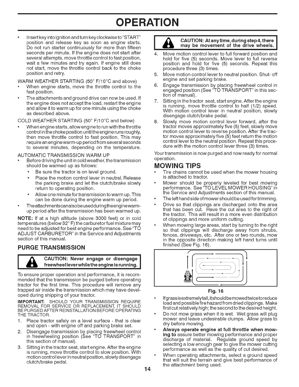
•When mowing large areas, start by turning to the right
so that clippings will discharge away from shrubs,
fences, driveways, etc. After one or two rounds, mow
in the opposite direction making left hand turns until
finished (See Fig. 16).
f
lr
(
Fig. 16
•Ifgrassisextremelytall, itshouldbe mowedtwiceto reduce
load and possible fire hazard from dried clippings. Make
first cut relatively high; the second to the desired height.
•Do not mow grass when it is wet. Wet grass will plug
mower and leave undesirable clumps. Allow grass to
dry before mowing.
•Always operate engine at full throttle when mow=
ing to assure better mowing performance and proper
discharge of material. Regulate ground speed by
selecting a low enough gear to give the mower cutting
performance as well as the quality of cut desired.
•When operating attachments, select a ground speed
that will suit the terrain and give best performance of
the attachment being used.
MAINTENANCE
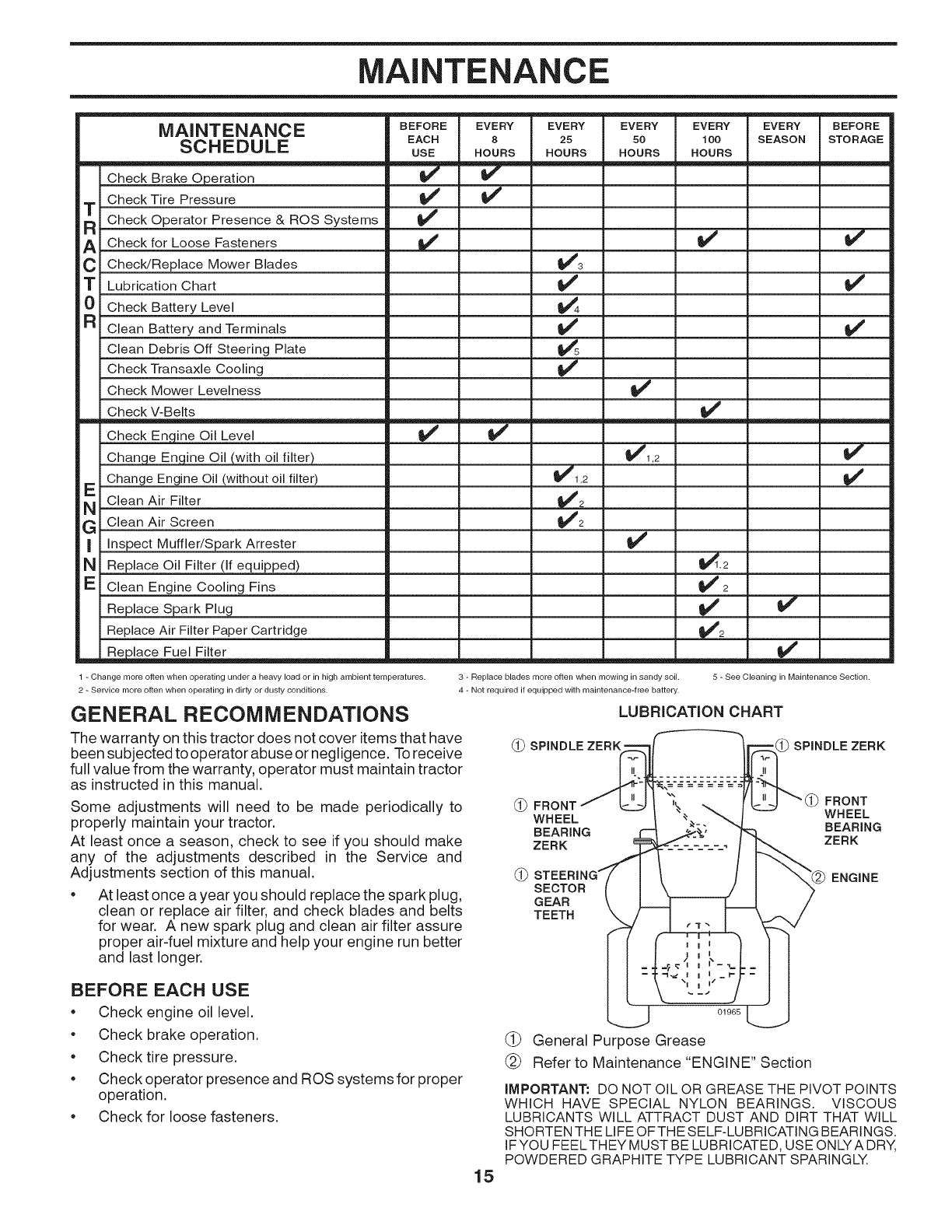
MAINTENANCE
SCHEDULE
Check Brake Operation
Check Tire Pressure
T Check Operator Presence & ROS Systems
ACheck for Loose Fasteners
CCheck/Replace Mower Blades
TLubrication Chart
0 Check Battery Level
R Clean Battery and Terminals
Clean Debris Off Steering Plate
Check Transaxle Cooling
Check Mower Levelness
Check V-Belts
Check Engine Oil Level
Change Enqine Oil (with oil filter)
Change Engine Oil (without oil filter)
E Clean Air Filter
G Clean Air Screen
I Inspect Muffler/Spark Attester
N Replace Oil Filter (if equipped)
E Clean Engine Cooling Fins
Replace Spark Plug
Replace Air Filter Paper Cartridge
m R_lace Fuel Filter
BEFORE
EACH
USE
v"
v'
v"
v"
EVERY
8
HOURS
EVERY
25
HOURS
v"
_1,2
V"2
V'2
EVERY
50
HOURS
v'
_1,2
v"
_,,,,,..,=,,=====.,=_
EVERY
100
HOURS
v'
v"
_,2
v"2
V'
EVERY
SEASON
v"
v'
BEFORE
STORAGE
v"
v'
V'
v'
1 - Change more often when operating under a heavy load or in high ambient temperatures.
2 - Service more often when operating in dirty or dusty conditions.
GENERAL RECOMMENDATIONS
The warranty on this tractor does not cover items that have
been subjected to operator abuse or negligence. To receive
full value from the warranty, operator must maintain tractor
as instructed in this manual.
Some adjustments will need to be made periodically to
properly maintain your tractor.
At least once a season, check to see if you should make
any of the adjustments described in the Service and
Adjustments section of this manual.
• At least once a year you should replace the spark plug,
clean or replace air filter, and check blades and belts
for wear. A new spark plug and clean air filter assure
proper air-fuel mixture and help your engine run better
and last longer.
3 - Replace blades more often when mowing in sandy soil. 5 - See Cleaning in Maintenance Section.
4 - Not required if equipped with maintenance-free battery.
LUBRICATION CHART
(_ SPINDLE ZERK' SPINDLE ZERK
(_FRONT FRONT
WHEEL WHEEL
BEARING BEARING
ZERK ZERK
SECTOR
GEAR
TEETH
ENGINE
BEFORE EACH USE
Check engine oil level.
•Check brake operation.
Check tire pressure.
•Check operator presence and ROS systems for proper
operation.
Check for loose fasteners.
15
01965
(_ General Purpose Grease
(_ Refer to Maintenance "ENGINE" Section
IMPORTANT: DO NOT OIL OR GREASE THE PIVOT POINTS
WHICH HAVE SPECIAL NYLON BEARINGS. VISCOUS
LUBRICANTS WILL ATTRACT DUST AND DIRT THAT WILL
SHORTEN THE LIFE OFTHE SELF-LUBRICATING BEARINGS.
IFYOU FEELTHEY MUST BE LUBRICATED, USE ONLYA DRY,
POWDERED GRAPHITE TYPE LUBRICANT SPARINGLY.
MAINTENANCE
TRACTOR
Always observe safety rules when performing any
maintenance.
BRAKE OPERATION
If tractor requires more than five (5) feet to stop at highest
speed in highest gear on a level, dry concrete or paved
surface, then brake must be checked and adjusted. (See
"TO CHECK BRAKE" in the Service and Adjustments
section of this manual).
TIRES
* Maintain proper air pressure in all tires (See the sides
of tires for proper PSI).
, Keep tires free of gasoline, oil, or insect control
chemicals which can harm rubber.
, Avoid stumps, stones, deep ruts, sharp objects and
other hazards that may cause tire damage.
NOTE: To seal tire punctures and prevent flat tires due
to slow leaks, tire sealant may be purchased from your
local parts dealer. Tire sealant also prevents tire dry rot
and corrosion.
OPERATOR PRESENCE SYSTEM AND REVERSE
OPERATION SYSTEM (ROS) (See Fig. 17)
Be sure operator presence and reverse operation systems
are working properly. If your tractor does not function as
described, repair the problem immediately.
• The engine should not start unless the brake pedal is
fully depressed, and the attachment clutch control is
in the disengaged position.
CHECK OPERATOR PRESENCE SYSTEM
•When the engine is running, any attempt bythe operator
to leave the seat without first setting the parking brake
should shut off the engine.
• When the engine is running and the attachment clutch
is engaged, any attempt by the operator to leave the
seat should shut off the engine.
• The attachment clutch should never operate unless
the operator is in the seat.
CHECK REVERSE OPERATION (ROS) SYSTEM
•When the engine is running with the ignition switch in
the engine "ON" position and the attachment clutch
engaged, any attempt by the operator to shift into
reverse should shut off the engine.
• When the engine is running with the ignition switch
in the ROS "ON" position and the attachment clutch
engaged, any attempt by the operator to shift into
reverse should NOT shut off the engine.
ROS "ON"
POSITION ENGINE "ON" POSITION
(NORMAL OPERATING)
Fig. 17
BLADE CARE
For best results mower blades must be kept sharp. Replace
bent or damaged blades.
_ CAUTION: Use onlya replacement blade ap=
proved by the manufacturer of your tractor.
Using ablade not approved by the manu=
facturer of your tractor is hazardous, could
damage your tractor and void your warranty.
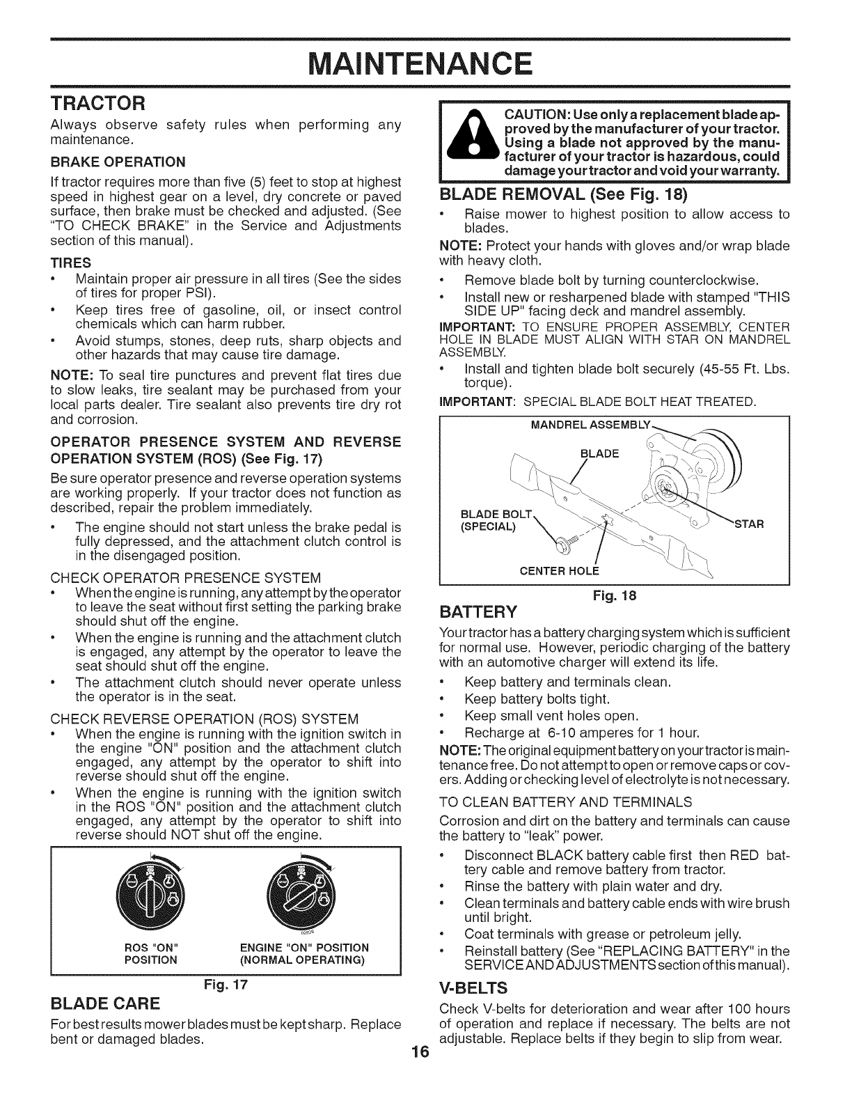
BLADE REMOVAL (See Fig. 18)
• Raise mower to highest position to allow access to
blades.
NOTE: Protect your hands with gloves and/or wrap blade
with heavy cloth.
• Remove blade bolt by turning counterclockwise.
• Install new or resharpened blade with stamped "THIS
SIDE UP" facing deck and mandrel assembly.
iMPORTANT: TO ENSURE PROPER ASSEMBLY, CENTER
HOLE IN BLADE MUST ALIGN WITH STAR ON MANDREL
ASSEMBLY.
•Install and tighten blade bolt securely (45-55 Ft. Lbs.
torque).
iMPORTANT: SPECIAL BLADE BOLT HEATTREATED.
BLADE BOLT
(SPECIAL)
16
CENTER HOLE
Fig. 18
BATTERY
Your tractor has a battery charging system which is sufficient
for normal use. However, periodic charging of the battery
with an automotive charger will extend its life.
• Keep battery and terminals clean.
• Keep battery bolts tight.
• Keep small vent holes open.
• Recharge at 6-10 amperes for 1 hour.
NOTE: The original equipment battery on your tractor ismain-
tenance free. Do not attempt to open or remove caps or cov-
ers. Adding or checking level of electrolyte is not necessary.
TO CLEAN BATTERY AND TERMINALS
Corrosion and dirt on the battery and terminals can cause
the battery to "leak" power.
• Disconnect BLACK battery cable first then RED bat-
tery cable and remove battery from tractor.
• Rinse the battery with plain water and dry.
• Clean terminals and battery cable ends with wire brush
until bright.
• Coat terminals with grease or petroleum jelly.
• Reinstall battery (See "REPLACING BATTERY" inthe
SERVICEAND ADJUSTMENTS section ofthismanual).
V=BELTS
Check V-belts for deterioration and wear after 100 hours
of operation and replace if necessary. The belts are not
adjustable. Replace belts if they begin to slip from wear.
MAINTENANCE
TRANSAXLE MAINTENANCE
The transmission fan and cooling fins should be kept clean
to assure proper cooling.
Do not attempt to clean fan or transmission while engine
is running or while the transmission is hot. To prevent pos-
sible damage to seals, do not use high pressure water or
steam to clean transmission.
• Inspect cooling fan to be sure fan blades are intact and
clean.
• Inspect cooling fins for dirt, grass clippings and other
materials. To prevent damage to seals, do not use com-
pressed air or high pressure sprayer to clean cooling fins.
TRANSAXLE PUMP FLUID
The transaxle was sealed at the factory and fluid mainte-
nance is not required for the life of the transaxle. Should
the transaxle ever leak or require servicing, contact your
nearest authorized service center/department.
ENGINE
LUBRICATION
Only use high quality detergent oil rated with API service
classification SG-SL. Select the oil's SAE viscosity grade
according to your expected operating temperature.
SAE VISCOSITY GRADES
mm/
F -20 0 30 32 40 60 80 100
C -30 -2; -1; ; 1'0 20 30 4;
TEMPERATURE RANGE ANTICIPATED BEFORE NEXT OIL CHANGE
NOTE: Although multi-viscosity oils (5W30, 10W30 etc.)
improve starting in cold weather, they will result in increased
oil consumption when used above 32°R Check your engine
oil level more frequently to avoid possible engine damage
from running low on oil.
Change the oil after every 25 hours of operation or at least
once a year if the tractor is not used for 25 hours in one year.
Check the crankcase oil level before starting the engine
and after each eight (8) hours of operation. Tighten oil fill
cap/dipstick securely each time you check the oil level.
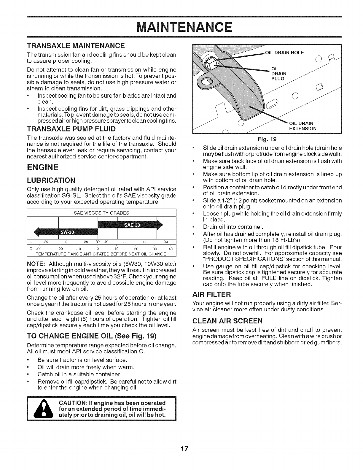
TO CHANGE ENGINE OIL (See Fig. 19)
Determine temperature range expected before oil change.
All oil must meet API service classification C.
* Be sure tractor is on level surface.
* Oil will drain more freely when warm.
* Catch oil in a suitable container.
* Remove oil fill cap/dipstick. Be careful not to allow dirt
to enter the engine when changing oil.
Afor an extended period of time immedi-
ately prior to draining oil, oil will be hot.
©
OiL
DRAIN
PLUG
EXTENSION
Fig. 19
• Slide oil drain extension under oil drain hole (drain hole
maybe flush with or protrude from engine block side wall).
• Make sure back face of oil drain extension isflush with
engine side wall.
• Make sure bottom lip of oil drain extension is lined up
with bottom of oil drain hole.
• Position a container to catch oil directly under front end
of oil drain extension.
• Slide a 1/2" (12 point) socket mounted on an extension
onto oil drain plug.
• Loosen plug while holding the oil drain extension firmly
in place.
• Drain oil into container.
• After oil has drained completely, reinstall oil drain plug.
(Do not tighten more than 13 Ft-Lb's)
• Refill engine with oil through oil fill dipstick tube. Pour
slowly. Do not overfill. For approximate capacity see
"PRODUCT SPECIFICATIONS" section of this manual.
• Use gauge on oil fill cap/dipstick for checking level.
Be sure dipstick cap is tightened securely for accurate
reading. Keep oil at "FULl" line on dipstick. Tighten
cap onto the tube securely when finished.
AIR FILTER
Your engine will not run properly using a dirty air filter. Ser-
vice air cleaner more often under dusty conditions.
CLEAN AIR SCREEN
Air screen must be kept free of dirt and chaff to prevent
engine damage from overheating. Clean with awire brush or
compressed airto remove dirt and stubborn dried gum fibers.
17
MAINTENANCE
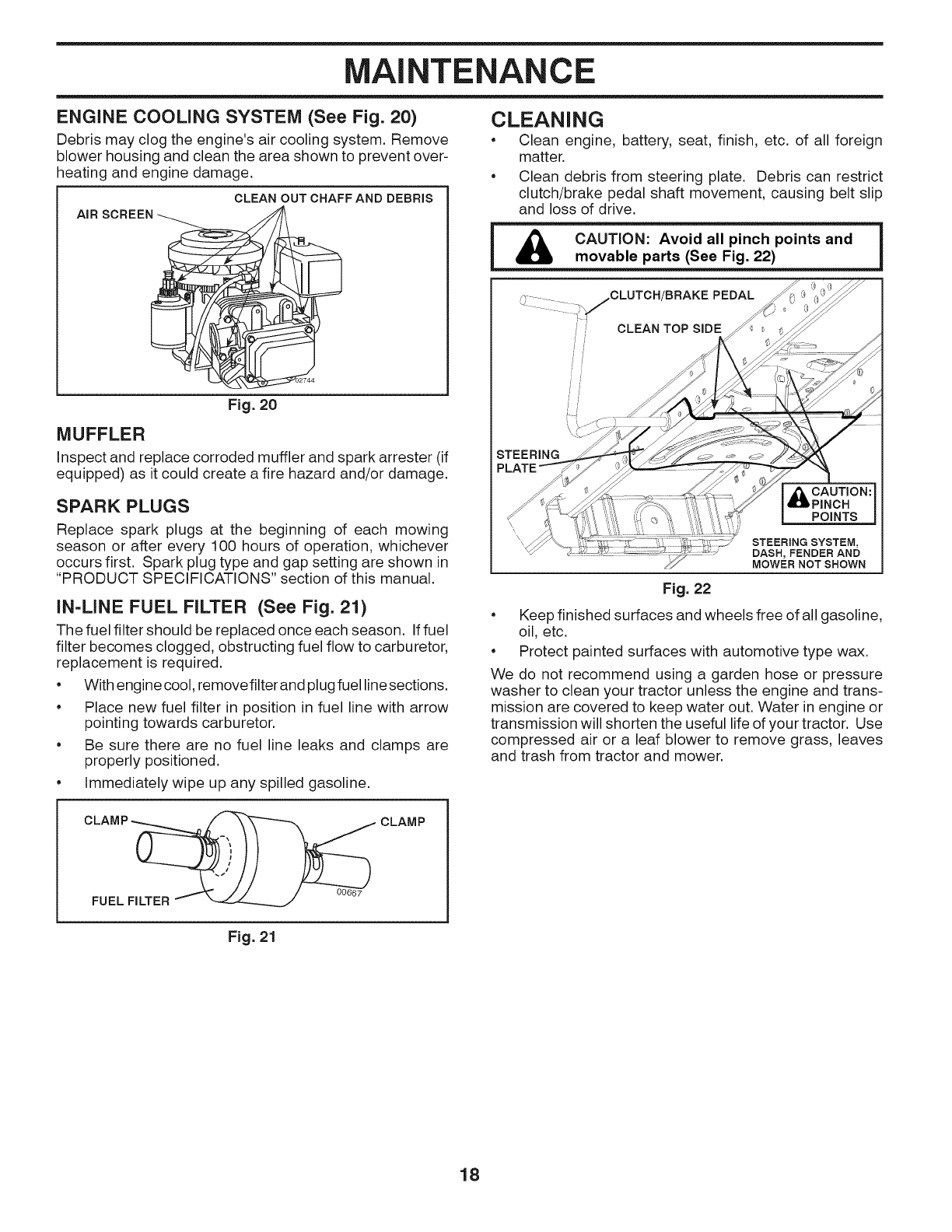
ENGINE COOLING SYSTEM (See Fig. 20)
Debris may clog the engine's air cooling system. Remove
blower housing and clean the area shown to prevent over-
heating and engine damage.
CLEAN OUT CHAFF AND DEBRIS
AIR
Fig. 20
MUFFLER
Inspect and replace corroded muffler and spark arrester (if
equipped) as it could create a fire hazard and/or damage.
SPARK PLUGS
Replace spark plugs at the beginning of each mowing
season or after every 100 hours of operation, whichever
occurs first. Spark plug type and gap setting are shown in
"PRODUCT SPECIFICATIONS" section of this manual.
IN=LINE FUEL FILTER (See Fig. 21)
The fuel filter should be replaced once each season. Iffuel
filter becomes clogged, obstructing fuel flow to carburetor,
replacement is required.
• With engine cool, remove filter and plug fuel linesections.
• Place new fuel filter in position in fuel line with arrow
pointing towards carburetor.
• Be sure there are no fuel line leaks and clamps are
properly positioned.
• Immediately wipe up any spilled gasoline.
I CLAMP __----_
FUEL FILTER _ J 00667
Fig. 21
CLAMP
CLEANING
• Clean engine, battery, seat, finish, etc. of all foreign
matter.
• Clean debris from steering plate. Debris can restrict
clutch/brake pedal shaft movement, causing belt slip
and loss of drive.
iAO O 'OO: vo'Oa" 'nc o'n'°onOi
movable parts (See Fig. 22)
.................. /CLUTCH/BRAKE PEDAL
CLEAN TOP SIDE
j
i J
i J
STEERING
_ AUTI ON:
PINCH
POINTS
STEERING SYSTEM,
DASH, FENDER AND
MOWER NOT SHOWN
Fig. 22
• Keep finished surfaces and wheels free of all gasoline,
oil, etc.
• Protect painted surfaces with automotive type wax.
We do not recommend using a garden hose or pressure
washer to clean your tractor unless the engine and trans-
mission are covered to keep water out. Water in engine or
transmission will shorten the useful life of your tractor. Use
compressed air or a leaf blower to remove grass, leaves
and trash from tractor and mower.
18
SERVICE AND ADJUSTMENTS
WARNING: TO AVOID SERIOUS INJURY, BEFORE PERFORMING ANY SERVICE OR ADJUSTMENTS:
Depress brake pedal fully and set parking brake.
Place motion control lever in neutral position.
*Place attachment clutch in "DISENGAGED" position.
*Turn ignition key to "STOP" and remove key.
*Make sure the blades and all moving parts have completely stopped.
*Disconnectsparkp_ugwirefromsparkp_ugandp_acewirewhereitcannotcomeincontactwithp_ug_
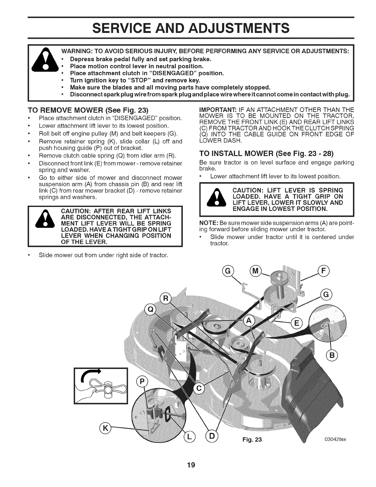
TO REMOVE MOWER (See Fig. 23)
• Place attachment clutch in "DISENGAGED" position.
• Lower attachment lift lever to its lowest position.
• Roll belt off engine pulley (M) and belt keepers (G).
• Remove retainer spring (K), slide collar (L) off and
push housing guide (P) out of bracket.
•Remove clutch cable spring (Q) from idler arm (R).
•Disconnect front link (E) from mower - remove retainer
spring and washer.
•Go to either side of mower and disconnect mower
suspension arm (A) from chassis pin (B) and rear lift
link (C) from rear mower bracket (D) - remove retainer
springs and washers.
&CAUTION: AFTER REAR LIFT LINKS
ARE DISCONNECTED, THE ATTACH=
MENT LIFT LEVER WILL BE SPRING
LOADED. HAVE ATIGHT GRIP ON LIFT
LEVER WHEN CHANGING POSITION
OF THE LEVER.
•Slide mower out from under right side of tractor.
IMPORTANT: IF AN ATTACHMENT OTHER THAN THE
MOWER IS TO BE MOUNTED ON THE TRACTOR,
REMOVE THE FRONT LINK (E) AND REAR LIFT LINKS
(C) FROM TRACTOR AND HOOKTHE CLUTCH SPRING
(Q) INTO THE CABLE GUIDE ON FRONT EDGE OF
LOWER DASH.
TO iNSTALL MOWER (See Fig. 23 - 28)
Be sure tractor is on level surface and engage parking
brake.
•Lower attachment lift lever to its lowest position.
CAUTION: LIFT LEVER IS SPRING
LOADED. HAVE A TIGHT GRIP ON
LIFT LEVER, LOWER IT SLOWLY AND
ENGAGE iN LOWEST POSITION.
NOTE: Be sure mower side suspension arms (A) are point-
ing forward before sliding mower under tractor.
•Slide mower under tractor until it is centered under
tractor.
%
Fig. 23 03042tex
19
SERVICE AND ADJUSTMENTS
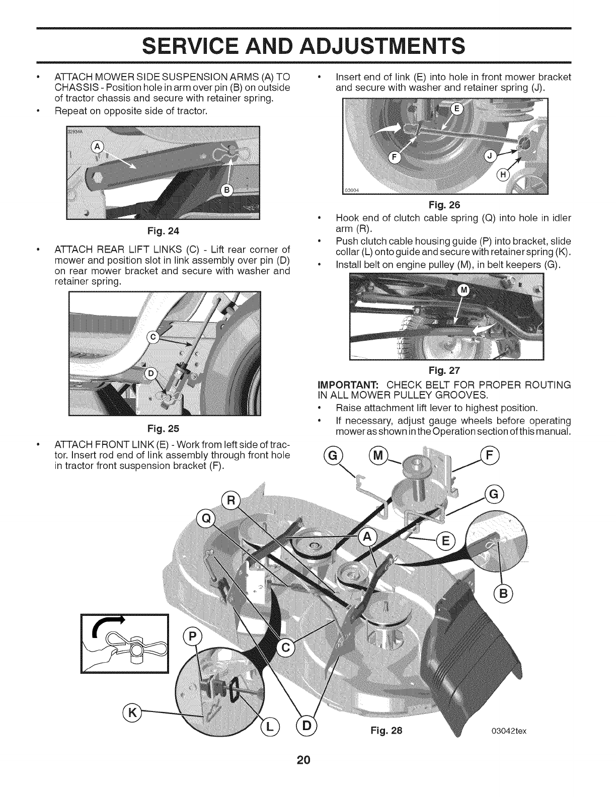
• ATTACH MOWER SIDE SUSPENSION ARMS (A) TO
CHASSIS - Position hole in arm over pin (B) on outside
of tractor chassis and secure with retainer spring.
• Repeat on opposite side of tractor.
Fig. 24
• Insert end of link (E) into hole in front mower bracket
and secure with washer and retainer spring (J).
ATTACH REAR LIFT LINKS (C) - Lift rear corner of
mower and position slot in link assembly over pin (D)
on rear mower bracket and secure with washer and
retainer spring.
Fig. 25
Fig. 26
• Hook end of clutch cable spring (Q) into hole in idler
arm (R).
• Push clutch cable housing guide (P) into bracket, slide
collar (L) onto guide and secure with retainer spring (K).
• Install belt on engine pulley (M), in belt keepers (G).
ATTACH FRONT LINK (E) - Work from left side of trac-
tor. Insert rod end of link assembly through front hole
in tractor front suspension bracket (F).
Fig. 27
iMPORTANT: CHECK BELT FOR PROPER ROUTING
IN ALL MOWER PULLEY GROOVES.
• Raise attachment lift lever to highest position.
• If necessary, adjust gauge wheels before operating
mower as shown inthe Operation section of this manual.
Fig. 28 03042tex
2O
SERVICE AND ADJUSTMENTS
TO LEVEL MOWER
Make sure tires are properly inflated to the PSI shown on
tires. If tires are over or under inflated, it may affect the
appearance of your lawn and lead you to think the mower
is not adjusted properly.
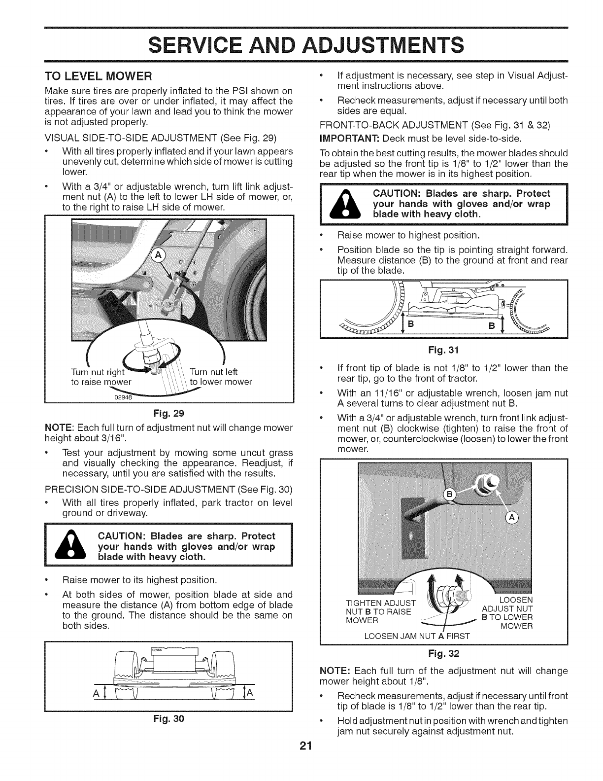
VISUAL SIDE-TO-SIDE ADJUSTMENT (See Fig. 29)
• With all tires properly inflated and if your lawn appears
unevenly cut, determine which side of mower is cutting
lower.
• With a 3/4" or adjustable wrench, turn lift link adjust-
ment nut (A) to the left to lower LH side of mower, or,
to the right to raise LH side of mower.
Turn nut rig Turn nut left
to raise mower to lower mower
Fig. 29
NOTE: Each full turn of adjustment nut will change mower
height about 3/16".
• Test your adjustment by mowing some uncut grass
and visually checking the appearance. Readjust, if
necessary, until you are satisfied with the results.
PRECISION SIDE-TO-SIDE ADJUSTMENT (See Fig. 30)
• With all tires properly inflated, park tractor on level
ground or driveway.
CAUTION: Blades are sharp. Protect
your hands with gloves and/or wrap
blade with heavy cloth.
e
e
Raise mower to its highest position.
At both sides of mower, position blade at side and
measure the distance (A) from bottom edge of blade
to the ground. The distance should be the same on
both sides.
AI L- W Lf IA
Fig. 30
21
• If adjustment is necessary, see step in Visual Adjust-
ment instructions above.
• Recheck measurements, adjust if necessary until both
sides are equal.
FRONT-TO-BACK ADJUSTMENT (See Fig. 31 & 32)
IMPORTANT: Deck must be level side-to-side.
To obtain the best cutting results, the mower blades should
be adjusted so the front tip is 1/8" to 1/2" lower than the
rear tip when the mower is in its highest position.
i & CAUTION: Blades are sharp. Protect
your hands with gloves and/or wrap
blade with heavy cloth.
• Raise mower to highest position.
Position blade so the tip is pointing straight forward.
Measure distance (B) to the ground at front and rear
tip of the blade.
¢'_- ee
Fig. 31
If front tip of blade is not 1/8" to 1/2" lower than the
rear tip, go to the front of tractor.
With an 11/16" or adjustable wrench, loosen jam nut
A several turns to clear adjustment nut B.
With a 3/4" or adjustable wrench, turn front link adjust-
ment nut (B) clockwise (tighten) to raise the front of
mower, or, counterclockwise (loosen) to lower the front
mower.
TIGHTEN ADJUST LOOSEN
NUT B TO RAISE ADJUST NUT
MOWER ....... B TO LOWER
MOWER
LOOSEN JAM NUT A FIRST
Fig. 32
NOTE: Each full turn of the adjustment nut will change
mower height about 1/8".
• Recheck measurements, adjust if necessary until front
tip of blade is 1/8" to 1/2" lower than the rear tip.
• Hold adjustment nut inposition with wrench and tighten
jam nut securely against adjustment nut.
SERVICE AND ADJUSTMENTS
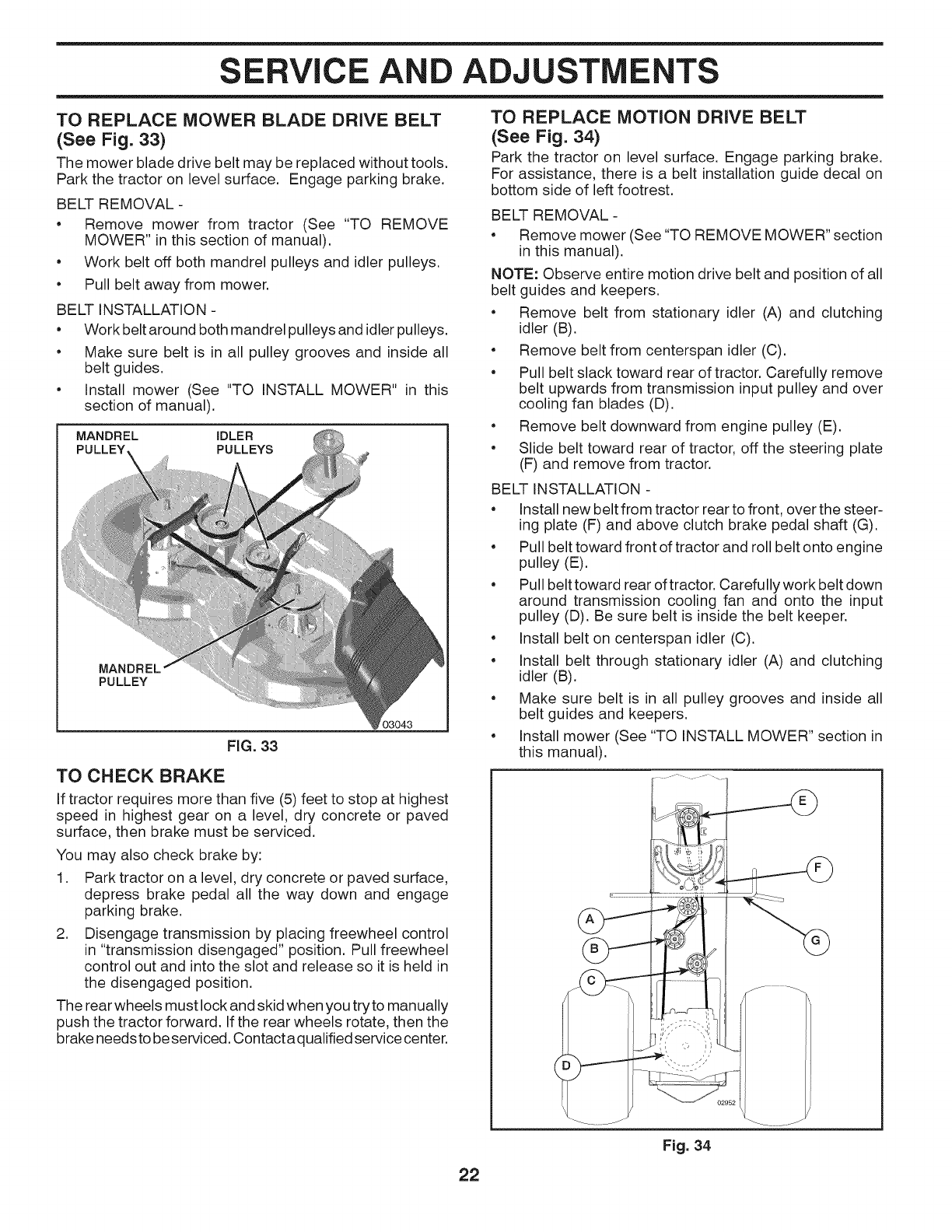
TO REPLACE MOWER BLADE DRIVE BELT
(See Fig. 33)
The mower blade drive belt may be replaced without tools.
Park the tractor on level surface. Engage parking brake.
BELT REMOVAL -
•Remove mower from tractor (See "TO REMOVE
MOWER" in this section of manual).
•Work belt off both mandrel pulleys and idler pulleys.
•Pull belt away from mower.
BELT INSTALLATION -
•Work belt around both mandrel pulleys and idler pulleys.
•Make sure belt is in all pulley grooves and inside all
belt guides.
•Install mower (See "TO INSTALL MOWER" in this
section of manual).
MANDREL IDLER
PULLEY PULLEYS
PULLEY
03043
FiG. 33
TO CHECK BRAKE
If tractor requires more than five (5) feet to stop at highest
speed in highest gear on a level, dry concrete or paved
surface, then brake must be serviced.
You may also check brake by:
1. Park tractor on a level, dry concrete or paved surface,
depress brake pedal all the way down and engage
parking brake.
2. Disengage transmission by placing freewheel control
in "transmission disengaged" position. Pull freewheel
control out and into the slot and release so it is held in
the disengaged position.
The rear wheels must lock and skid when you try to manually
push the tractor forward. If the rear wheels rotate, then the
brake needs to be serviced. Contact a qualified service center.
22
TO REPLACE MOTION DRIVE BELT
(See Fig. 34)
Park the tractor on level surface. Engage parking brake.
For assistance, there is a belt installation guide decal on
bottom side of left footrest.
BELT REMOVAL -
•Remove mower (See "TO REMOVE MOWER" section
in this manual).
NOTE: Observe entire motion drive belt and position of all
belt guides and keepers.
•Remove belt from stationary idler (A) and clutching
idler (B).
•Remove belt from centerspan idler (C).
•Pull belt slack toward rear of tractor. Carefully remove
belt upwards from transmission input pulley and over
cooling fan blades (D).
•Remove belt downward from engine pulley (E).
•Slide belt toward rear of tractor, off the steering plate
(F) and remove from tractor.
BELT INSTALLATION -
•Install new belt from tractor rear to front, over the steer-
ing plate (F) and above clutch brake pedal shaft (G).
•Pull belt toward front of tractor and roll belt onto engine
pulley (E).
•Pull belt toward rear oftractor. Carefully work belt down
around transmission cooling fan and onto the input
pulley (D). Be sure belt is inside the belt keeper.
•Install belt on centerspan idler (C).
•Install belt through stationary idler (A) and clutching
idler (B).
•Make sure belt is in all pulley grooves and inside all
belt guides and keepers.
•Install mower (See "TO INSTALL MOWER" section in
this manual).
Fig. 34
SERVICE AND ADJUSTMENTS
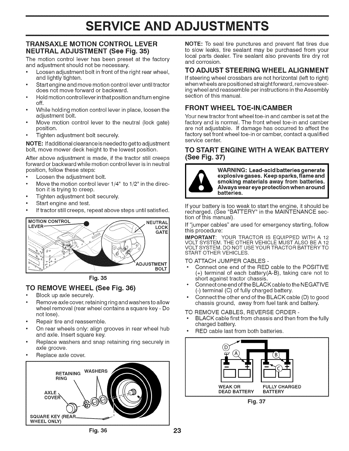
TRANSAXLE MOTION CONTROL LEVER
NEUTRAL ADJUSTMENT (See Fig. 35)
The motion control lever has been preset at the factory
and adjustment should not be necessary.
• Loosen adjustment bolt infront of the right rear wheel,
and lightly tighten.
• Start engine and move motion control lever until tractor
does not move forward or backward.
• Hold motion control lever in that position andturn engine
off.
• While holding motion control lever in place, loosen the
adjustment bolt.
• Move motion control lever to the neutral (lock gate)
position.
• Tighten adjustment bolt securely.
NOTE: Ifadditional clearance is neededto getto adjustment
bolt, move mower deck height to the lowest position.
After above adjustment is made, if the tractor still creeps
forward or backward while motion control lever is in neutral
position, follow these steps:
• Loosen the adjustment bolt.
• Move the motion control lever 1/4" to 1/2" in the direc-
tion it is trying to creep.
• Tighten adjustment bolt securely.
• Start engine and test.
• Iftractor still creeps, repeat above steps until satisfied.
MOTION CONTROL NEUTRAL
LOCK
GATE
,..... ADJ USTMENT
,,," BOLT
Fig. 35
TO REMOVE WHEEL (See Fig. 36)
• Block up axle securely.
• Remove axle cover, retaining ring and washers to allow
wheel removal (rear wheel contains a square key - Do
not lose).
• Repair tire and reassemble.
• On rear wheels only: align grooves in rear wheel hub
and axle. Insert square key.
• Replace washers and snap retaining ring securely in
axle groove.
• Replace axle cover.
WASHERS
RETAINING
RING
AXLE
SQUARE KEY (REAR i
WHEEL ONLY)
NOTE: To seal tire punctures and prevent flat tires due
to slow leaks, tire sealant may be purchased from your
local parts dealer. Tire sealant also prevents tire dry rot
and corrosion.
TO ADJUST STEERING WHEEL ALIGNMENT
If steering wheel crossbars are not horizontal (left to right)
when wheels are positioned straightforward, remove steer-
ing wheel and reassemble per instructions in the Assembly
section of this manual.
FRONT WHEEL TOE=IN/CAMBER
Your new tractor front wheel toe-in and camber isset at the
factory and is normal. The front wheel toe-in and camber
are not adjustable. If damage has occurred to affect the
factory set front wheel toe-in or camber, contact a qualified
service center.
TO START ENGINE WITH A WEAK BATTERY
(See Fig. 37)
WARNING: Lead=acid batteries generate
explosive gases. Keep sparks, flame and
smoking materials away from batteries.
Always wear eye protection when around
batteries.
If your battery is too weak to start the engine, it should be
recharged. (See "BATTERY" in the MAINTENANCE sec-
tion of this manual).
If "jumper cables" are used for emergency starting, follow
this procedure:
iMPORTANT: YOUR TRACTOR IS EQUIPPED WITH A 12
VOLT SYSTEM. THE OTHER VEHICLE MUST ALSO BE A 12
VOLT SYSTEM. DO NOT USE YOUR TRACTOR BATTERYTO
START OTHER VEHICLES.
TO ATTACH JUMPER CABLES -
• Connect one end of the RED cable to the POSITIVE
(+) terminal of each battery(A-B), taking care not to
short against tractor chassis.
• Connect one end of the BLACKcable to the NEGATIVE
(-) terminal (C) of fully charged battery.
• Connect the other end of the BLACK cable (D) to good
chassis ground, away from fuel tank and battery.
TO REMOVE CABLES, REVERSE ORDER -
• BLACK cable first from chassis and then from the fully
charged battery.
• RED cable last from both batteries.
WEAK OR FULLY CHARGED
DEAD BATTERY BATTERY
Fig. 37
Fig. 36 23
SERVICE AND ADJUSTMENTS
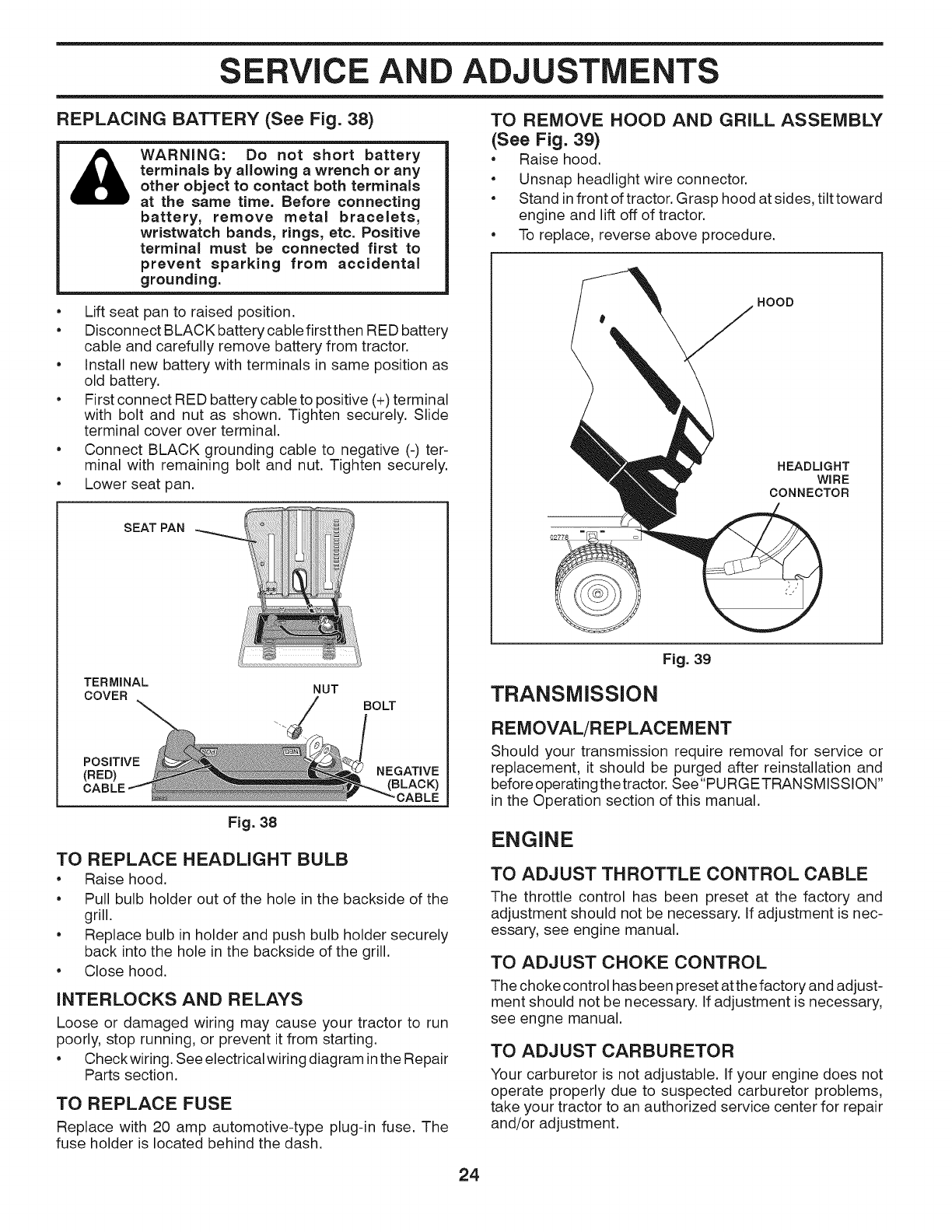
REPLACING BATTERY (See Fig. 38)
WARNING: Do not short battery
terminals by allowing a wrench or any
other object to contact both terminals
at the same time. Before connecting
battery, remove metal bracelets,
wristwatch bands, rings, etc. Positive
terminal must be connected first to
prevent sparking from accidental
grounding.
•Lift seat pan to raised position.
•Disconnect BLACK battery cable first then RED battery
cable and carefully remove battery from tractor.
• Install new battery with terminals in same position as
old battery.
• First connect RED battery cable to positive (+) terminal
with bolt and nut as shown. Tighten securely. Slide
terminal cover over terminal.
• Connect BLACK grounding cable to negative (-) ter-
minal with remaining bolt and nut. Tighten securely.
•Lower seat pan.
SEATPAN ¸
TERMINAL
COVER NUT BOLT
POSITIVE
(RED)
Fig. 38
NEGATIVE
(BLACK)
CABLE
TO REPLACE HEADLIGHT BULB
•Raise hood.
• Pull bulb holder out of the hole in the backside of the
grill.
• Replace bulb in holder and push bulb holder securely
back into the hole in the backside of the grill.
• Close hood.
INTERLOCKS AND RELAYS
Loose or damaged wiring may cause your tractor to run
poorly, stop running, or prevent it from starting.
• Checkwiring. See electrical wiring diagram in the Repair
Parts section.
TO REPLACE FUSE
Replace with 20 amp automotive-type plug-in fuse. The
fuse holder is located behind the dash.
TO REMOVE HOOD AND GRILL ASSEMBLY
(See Fig. 39)
•Raise hood.
• Unsnap headlight wire connector.
• Stand in front of tractor. Grasp hood at sides, tilt toward
engine and lift off of tractor.
• To replace, reverse above procedure.
HOOD
HEADLIGHT
WIRE
CONNECTOR
Fig. 39
TRANSMISSION
REMOVAL/REPLACEMENT
Should your transmission require removal for service or
replacement, it should be purged after reinstallation and
before operatingthetractor. See"PURGETRANSMISSION"
in the Operation section of this manual.
ENGINE
TO ADJUST THROTTLE CONTROL CABLE
The throttle control has been preset at the factory and
adjustment should not be necessary. If adjustment is nec-
essary, see engine manual.
TO ADJUST CHOKE CONTROL
The choke control has been preset at the factory and adjust-
ment should not be necessary. If adjustment is necessary,
see engne manual.
TO ADJUST CARBURETOR
Your carburetor is not adjustable. If your engine does not
operate properly due to suspected carburetor problems,
take your tractor to an authorized service center for repair
and/or adjustment.
24
STORAGE
Immediately prepare your tractor for storage at the end
of the season or if the tractor will not be used for 30 days
or more.
WARNING: Never store the tractor with
gasoline in the tank inside a building
where fumes may reach an open flame
or spark. AIIowthe engineto cool before
storing in any enclosure.
TRACTOR
Remove mower from tractor for winter storage. When mower
isto be stored for a period oftime, clean itthoroughly, remove
all dirt, grease, leaves, etc. Store in a clean, dry area.
•Clean entire tractor (See "CLEANING" in the
Maintenance section of this manual).
•Inspect and replace belts, if necessary (See belt
replacement instructionsin the Service and Adjustments
section of this manual).
•Lubricate as shown in the Maintenance section of this
manual.
•Be sure that all nuts, bolts and screws are securely
fastened. Inspect moving parts for damage, breakage
and wear. Replace if necessary.
•Touch up all rusted or chipped paint surfaces; sand
lightly before painting.
BATTERY
•Fully charge the battery for storage.
•After a period of time in storage, battery may require
recharging.
•To help prevent corrosion and power leakage during
long periods of storage, battery cables should be
disconnected and battery cleaned thoroughly (see
"TO CLEAN BATTERY AND TERMINALS" in the
Maintenance section of this manual).
•After cleaning, leave cables disconnected and place
cables where they cannot come in contact with battery
terminals.
•If battery is removed from tractor for storage, do not
store battery directly on concrete or damp surfaces.
ENGINE
FUEL SYSTEM
IMPORTANT: IT IS IMPORTANTTO PREVENTGUM DEPOSITS
FROM FORMING IN ESSENTIAL FUEL SYSTEM PARTS SUCH
AS CARBURETOR, FUEL FILTER, FUEL HOSE, OR TANK
DURING STORAGE. ALSO, EXPERIENCE INDICATES THAT
ALCOHOL BLENDED FUELS (CALLED GASOHOL OR USING
ETHANOL OR METHANOL) CAN ATTRACT MOISTURE WHICH
LEADS TO SEPARATION AND FORMATION OFACIDS DURING
STORAGE. ACIDIC GAS CAN DAMAGE THE FUEL SYSTEM
OF AN ENGINE WHILE IN STORAGE.
•Empty the fuel tank by starting the engine and let it run
until the fuel lines and carburetor are empty.
•Never use engine or carburetor cleaner products in
the fuel tank or permanent damage may occur.
•Use fresh fuel next season.
NOTE: Fuel stabilizer is an acceptable alternative in
minimizing the formation of fuel gum deposits during storage.
Add stabilizer to gasoline in fuel tank or storage container.
Always follow the mix ratio found on stabilizer container.
Run engine at least 10 minutes after adding stabilizer to
allow the stabilizer to reach the carburetor. Do not empty
the gas tank and carburetor if using fuel stabilizer.
ENGINE OIL
Drain oil (with engine warm) and replace with clean engine oil.
(See "ENGINE" in the Maintenance section of this manual).
CYLINDER(S)
•Remove spark plug(s).
•Pour one ounce of oil through spark plug hole(s) into
cylinder(s).
•Turn ignitionkey to "START" position for a few seconds
to distribute oil.
•Replace with new spark plug(s).
OTHER
•Do not store gasoline from one season to another.
•Replace your gasoline can if your can starts to rust.
Rust and/or dirt in your gasoline will cause problems.
•If possible, store your tractor indoors and cover it to
give protection from dust and dirt.
•Cover your tractor with a suitable protective cover that
does not retain moisture. Do not use plastic. Plastic
cannot breathe which allows condensation to form and
will cause your tractor to rust.
IMPORTANT: NEVERCOVERTRACTORWHILE ENGINEAND
EXHAUST AREAS ARE STILL WARM.
25

TROUBLESHOOTING
PROBLEM
Will not start
Hard to start
Engine will not
turn over
Engine clicks but
will not start
Loss of power
Excessive
vibration
CAUSE
1. Out of fuel.
CORRECTION
1.
2. Engine not "CHOKED" properly.
3. Engine flooded.
4. Bad spark plug.
5. Dirty air filter.
6. Dirty fuel filter.
7. Water in fuel.
8.
9.
Loose or damaged wiring.
Carburetor out of adjustment.
10. Engine valves out of adjustment.
Fill fuel tank.
2. See "TO START ENGINE" in Operation section.
3. Wait several minutes before attempting to start.
4. Replace spark plug.
5. Clean/replace air filter.
6. Replace fuel filter.
7. Empty fuel tank and carburetor, refill tank with fresh
gasoline and replace fuel filter.
8. Check all wiring.
9. See "To Adjust Carburetor" in Service Adjustments
section.
10. Contact an authorized service center/department.
1. Dirty air filter.
2. Bad spark plug.
3. Weak or dead battery.
4. Dirty fuel filter.
5. Stale or dirty fuel.
6. Loose or damaged wiring.
7. Carburetor out of adjustment.
8. Engine valves out of adjustment.
1. Brake pedal not depressed.
2. Attachment clutch is engaged.
3. Weak or dead battery.
4. Blown fuse.
5. Corroded battery terminals.
6. Loose or damaged wiring.
7. Faulty ignition switch.
8. Faulty solenoid or starter.
9. Faulty operator presence switch(es).
1. Weak or dead battery.
2. Corroded battery terminals.
3. Loose or damaged wiring.
4. Faulty solenoid or starter.
1. Cutting too much grass/too fast.
2. Throttle in "CHOKE" position.
3. Build-up of grass, leaves, trash under mower.
4. Dirty air filter.
5. Low oil level/dirty oil.
6. Faulty spark plug.
7. Dirty fuel filter.
8. Stale or dirty fuel.
9. Water in fuel.
10. Spark plug wire loose.
11. Dirty engine air screen/fins.
12. Dirty/clogged muffler.
13. Loose or damaged wiring.
14. Carburetor out of adjustment.
15. Engine valves out of adjustment.
1. Worn, bent or loose blade.
2. Bent blade mandrel.
3. Loose/damaged part(s).
1. Clean/replace air filter.
2. Replace spark plug.
3. Recharge or replace battery.
4. Replace fuel filter.
5. Empty fuel tank and refill tank with fresh, clean gas.
6. Check all wiring.
7. See "To Adjust Carburetor" in Service Adjustments
section.
8. Contact an authorized service center/department.
1. Depress brake pedal.
2. Disengage attachment clutch.
3. Recharge or replace battery.
4. Replace fuse.
5. Clean battery terminals.
6. Check all wiring.
7. Check/replace ignition switch.
8. Check/replace solenoid or starter.
9. Contact an authorized service center/department.
1. Recharge or replace battery.
2. Clean battery terminals.
3. Check all wiring.
4. Check/replace solenoid or starter.
1. Raise cutting height/reduce speed.
2. Adjust throttle control.
3. Clean underside of mower housing.
4. Clean/replace air filter.
5. Check oil level/change oil.
6. Clean and regap or change spark plug.
7. Replace fuel filter.
8. Empty fuel tank and refill tank with fresh, clean gas.
9. Empty fuel tank and carburetor, refill tank with fresh
gasoline and replace fuel filter.
10. Connect and tighten spark plug wire.
11. Clean engine air screen/fins.
12. Clean/replace muffler.
13. Check all wiring.
14. See "To Adjust Carburetor" in Service Adjustments
15. Contact an authorized service center/department.
1. Replace blade. Tighten blade bolt.
2. Replace blade mandrel.
3. Tighten loose part(s). Replace damaged parts.
26

TROUBLESHOOTING
PROBLEM
Engine continues
to run when oper=
ator [eaves seat
with attachment
clutch engaged
Poor cut =uneven
Mower blades wi[[
not rotate
Poor grass
discharge
Headlight(s) not
working
(if so equipped)
Battery wii[ not
charge
Loss of drive
Engine "back-
fires" when turn=
ing engine "OFF"
Engine dies when
tractor is shifted
into reverse
CAUSE
1. Faulty operator-safety presence control
system.
CORRECTION
1. Check wiring, switches and connections. If not
corrected, contact an authorized service center/
department.
1. Worn, bent or loose blade.
2. Mower deck not level.
3. Buildup of grass, leaves, trash under mower.
4. Bent blade mandrel.
5. Clogged mower deck vent holes from
buildup of grass, leaves, and trash around
mandrels.
1. Obstruction in clutch mechanism.
2. Worn/damaged mower drive belt.
3. Frozen idler pulley.
4. Frozen blade mandrel.
1. Replace blade. Tighten blade bolt.
2. Level mower deck.
3. Clean underside of mower housing.
4. Replace blade mandrel.
5. Clean around mandrels to open vent holes.
1. Remove obstruction.
2. Replace mower drive belt.
3. Replace idler pulley.
4. Replace blade mandrel.
1. Engine speed too slow.
2. Travel speed too fast.
3. Wet grass.
4. Mower deck not level.
5. Low/uneven tire air pressure.
6. Worn, bent or loose blade.
1. Place throttle control in "FAST" position.
2. Shift to slower speed.
3. Allow grass to dry before mowing.
4. Level mower deck.
5. Check tires for proper air pressure.
6. Replace blade. Tighten blade bolt.
7. Buildup of grass, leaves, trash under mower.
8. Mower drive belt worn.
9. Blades improperly installed.
10. Improper blades used.
11. Ctoggedmowerdeckventhotesfrombuildup
of grass, leaves, trash around mandrels.
7. Clean underside of mower housing.
8. Replace mower drive belt.
9. Reinstall blades sharp edge down.
10. Replace with blades listed in parts manual.
11. Clean around mandrels to open vent holes.
1. Switch is "OFF".
2. Bulb(s) or lamp(s) burned out.
3. Faulty light switch.
4. Loose or damaged wiring.
5. Blown fuse.
1. Turn switch "ON".
2. Replace bulb(s) or lamp(s).
3. Check/replace light switch.
4. Check wiring and connections.
5. Replace fuse.
1. Bad battery cell(s).
2. Poor cable connections.
3. Faulty regulator (if so equipped).
4. Faulty alternator.
1. Freewheel control in "disengaged" position.
2. Debris on steering plate (if equipped).
3. Motion drive belt worn, damaged, or broken.
4. Air trapped in transmission during
shipment or servicing.
5. Axle key missing.
1. Engine throttle control not set between
half and full speed (fast) position before
stopping engine.
1. Reverse operation system (ROS) is not"ON"
while mower or other attachment is engaged.
1. Replace battery.
2. Check/clean all connections.
3. Replace regulator.
4. Replace alternator.
1. Place freewheel control in "engaged" position.
2. See "CLEANING" in the maintenance section.
3. Replace motion drive belt.
4. Purge transmission.
5. Install axle key at rear wheel. See "TO REMOVE
WHEEL" in the Service and Adjustments section.
1. Move throttle control between half and full speed
(fast) position before stopping engine.
1. Turn ignition key to ROS "ON" position. See
Operation section.
27
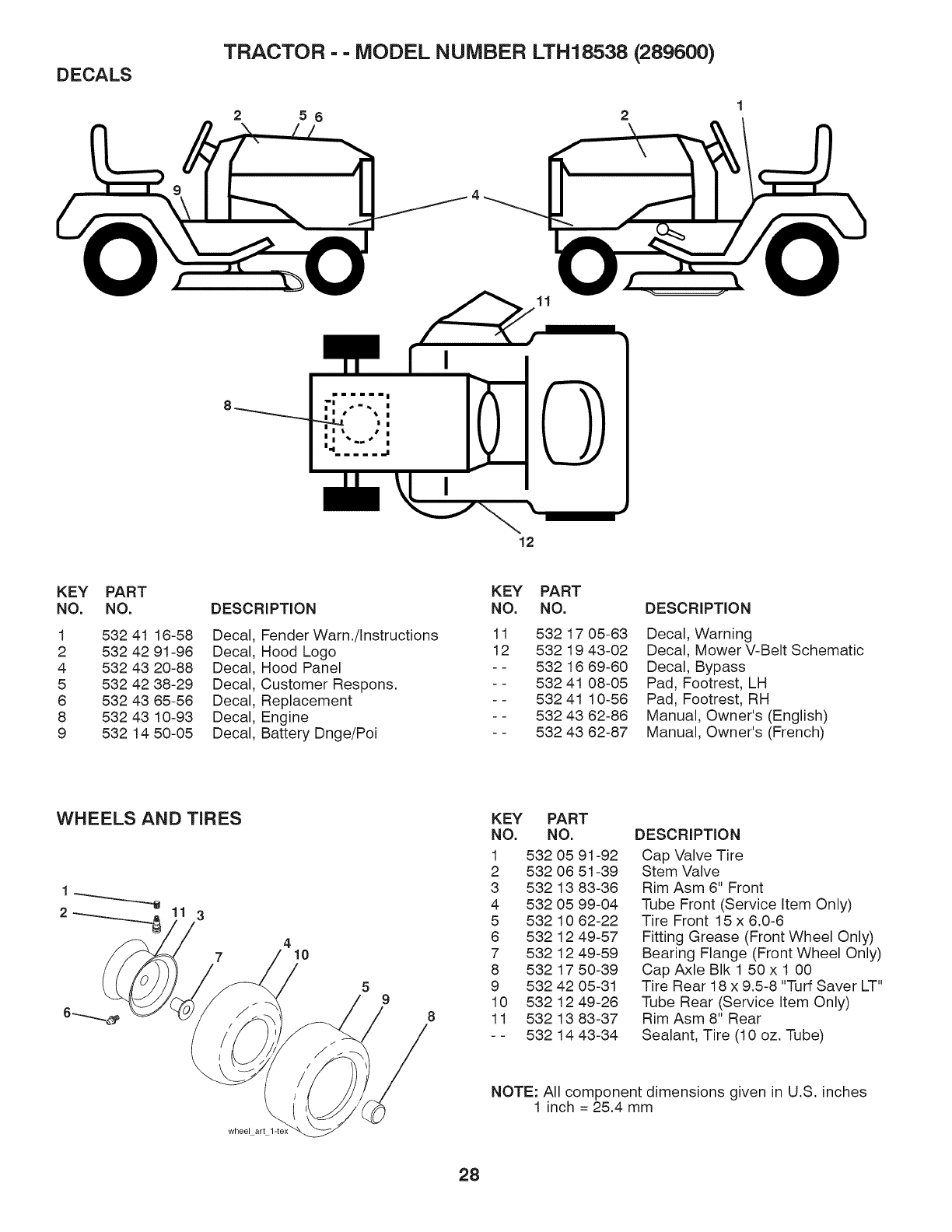
DECALS TRACTOR - - MODEL NUMBER LTH18538 (289600)
56 2
11
12
KEY
NO.
1
2
4
5
6
8
9
PART
NO. DESCRIPTION
532 41 16-58 Decal
532 42 91-96 Decal
532 43 20-88 Decal
532 42 38-29 Decal
532 43 65-56 Decal
532 43 10-93 Decal
532 1450-05 Decal
KEY PART
NO. NO.
Fender Warn./Instructions 11 532 17 05-63
Hood Logo 12 532 19 43-02
Hood Panel - - 532 16 69-60
Customer Respons. - - 532 41 08-05
Replacement - - 532 41 10-56
Engine - - 532 43 62-86
Battery Dnge/Poi - - 532 43 62-87
DESCRIPTION
Decal, Warning
Decal, Mower V-Belt Schematic
Decal, Bypass
Pad, Footrest, LH
Pad, Footrest, RH
Manual, Owner's (English)
Manual, Owner's (French)
WHEELS AND TIRES
1
23
7410
wheel art
9
KEY PART
NO. NO.
1 532 05 91-92
2 532 06 51-39
3 532 13 83-36
4 532 05 99-04
5 532 10 62-22
6 532 12 49-57
7 532 12 49-59
8 532 17 50-39
9 532 42 05-31
10 532 12 49-26
8 11 532 13 83-37
- - 532 14 43-34
DESCRIPTION
Cap Valve Tire
Stem Valve
Rim Asm 6" Front
Tube Front (Service Item Only)
Tire Front 15 x 6.0-6
Fitting Grease (Front Wheel Only)
Bearing Flange (Front Wheel Only)
Cap Axle BIk 1 50 x 1 00
Tire Rear 18 x 9.5-8 "Turf Saver LT"
Tube Rear (Service Item Only)
Rim Asm 8" Rear
Sealant, Tire (10 oz. Tube)
NOTE: All component dimensions given in U.S. inches
1 inch = 25.4 mm
28
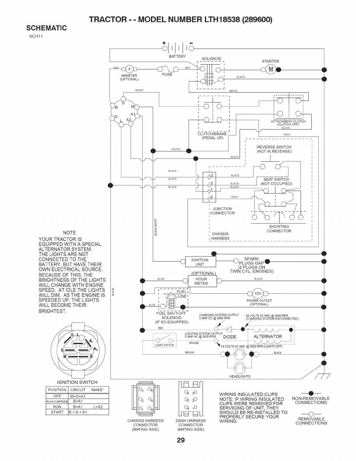
SCHEMATIC
SCH 11
TRACTOR - - MODEL NUMBER LTH18538 (289600)
NOTE
YOUR TRACTOR IS
EQUIPPED WITH A SPECIAL
ALTERNATOR SYSTEM.
THE LIGHTS ARE NOT
CONNECTED TO THE
BATTERY, BUT HAVE THEIR
OWN ELECTRICAL SOURCE.
BECAUSE OF THIS, THE
BRIGHTNESS OF THE LIGHTS
WILL CHANGE WITH ENGINE
SPEED. AT IDLE THE LIGHTS
WILL DIM. AS THE ENGINE IS
SPEEDED UP, THE LIGHTS
WILL BECOME THEIR
BRIGHTEST.
iGNiTiON SWITCH
POSITION CIRCUIT "MAKE"
OFF M+G+A1
RUN/OVERRIDE a+A1
RUN B+A1 L+A2
START B + S + A1
BATTERY SOLENOID
AMMETER FUSE
(OPTIONAL)
q
I
q
BLACK
BLACK
:i:io
_K I ATT,_,-C}qMENT C___JS--CH
I
I I (CLUTCH O
,,
GRAY
I (NOT IN REVERSE)
..... IJ
t _ BLACK
BLACK
BLACK
[
GRAY
JUNCTION
_CONNECTOR
SHORTING
CONNECTOR
CHASSIS
HARNESS
q
BLUE 4
A FUE_I
', 7/_NE,
I I
FUEL SHUT-OFF
IGNITION
UNIT
(OPTIONAL)
HOUR bMETER
O
SPARK A
PLUGS GAPW
(2 PLUGS ON
TWIN CYL, ENGINES)
POWER OUTLET
(OPTIONAL)
CHARGING SYSTEM OUTPUT 28 VOLTS AC MIN. @ 3600 RPM
SOLENOID 3 AMP DC @ 3600 RPM
(IF SO EQUIPPED) /2ARGING SYSTEM DISCONNECTED)
RED f r I
, UGHT,NG SYSTEM OUJ_ J_S_ _i
I 5AMP AC @ 3600 RPM DIODE I ALTERNATOR _ I
LIGHT SWITCH '_
I , L GHT SWR I 14 VOLTS AC MIN. @ 360ORPM (LIGHTSOFF)
HEADLIGHTS
Q
CHASSIS HARNESS DASH HARNESS
CONNECTOR CONNECTOR
(MATING SIDE) (MATING SIDE)
WIRING INSULATED CLIPS
NOTE: iF WIRING INSULATED
CLIPS WERE REMOVED FOR
SERVICING OF UNIT, THEY
SHOULD BE RE-INSTALLED TO
PROPERLY SECURE YOUR
WIRING,
qD
_D
_D
_D
qD
qD
q_
O-
NON-REMOVABLE
CONNECTIONS
O
REMOVABLE
CONNECTIONS
29
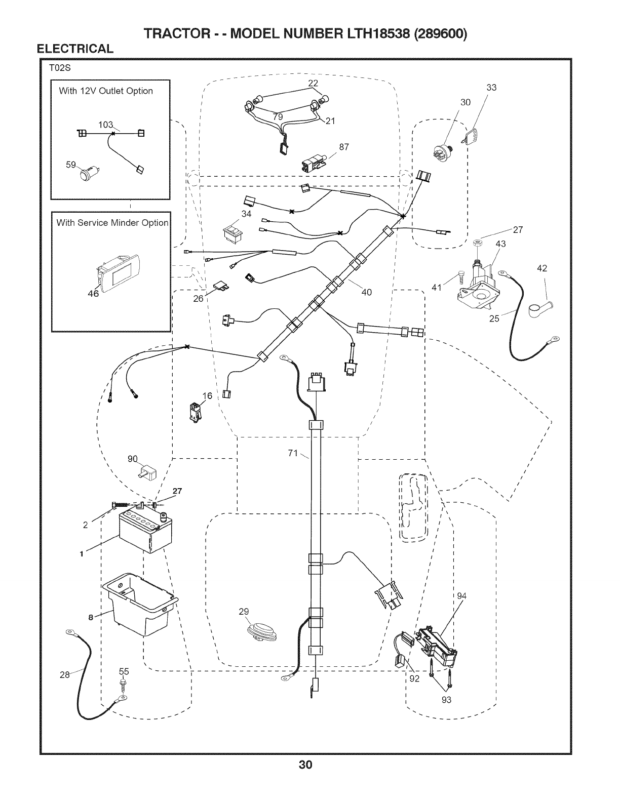
ELECTRICAL TRACTOR -- MODEL NUMBER LTH18538 (289600)
T02S
With 12V Outlet Option
I
With Service Minder Option
\
I
I
I
I
I f
I\J_--
I \ I
I \ k
I
I
I \1
]I
_ t
1 87
34
4O
t !
I
I
I
I
I
"f /I
33
I
I
\_27
43
42
16
z
29
71
q
I
I
3O

ELECTRICAL TRACTOR - - MODEL NUMBER LTH18538 (289600)
KEY PART
NO. NO. DESCRIPTION
1 532 16 34-65 Battery
2 874 76 04-12 Bolt Hex Head 1/4-20 x 3/4
8 532 19 32-28 Box Battery
16 532 17 61-38 Switch Interlock Push-In
21 532 40 02-52 Harness Socket Light w/4152J
22 532 00 41-52 Bulb Light
25 532 41 28-94 Cable Starter
26 5321751-58 Fuse
27 873 51 04-00 Nut Keps Hex 1/4-20 unc
28 532 19 88-85 Cable, Ground
29 532 40 15-45 Switch, Seat
30 532 19 33-50 Switch, Ign
33 532 41 19-35 Key/Chain
34 532 11 07-12 Switch Light/Reset
40 532 40 10-98 Harness Ign. Dash
41 817 72 04-08 ScrewThd Cut 1/4-20 x 1/2
42 532 13 15-63 Cover, Terminal
43 532 19 25-07 Solenoid
55 817 06 05-12 Screw Thdrol 5/16-18 x 3/4
71 532 40 04-49 Harness Chassis
79 532 17 52-42 Socket Asm Bulb Twistlock
87 532 19 78-02 Switch Interlock Clutch Cable
90 532 40 07-25 Cover, Terminal Battery
92 532 19 66-15 Harness Pigtail Reverse Switch
93 532 19 25-40 Screw Plastite 10-14 x 2.0
94 532 19 18-34 Module Reverse ROS
NOTE: All component dimensions given in U.S. inches
1inch = 25.4 mm
31
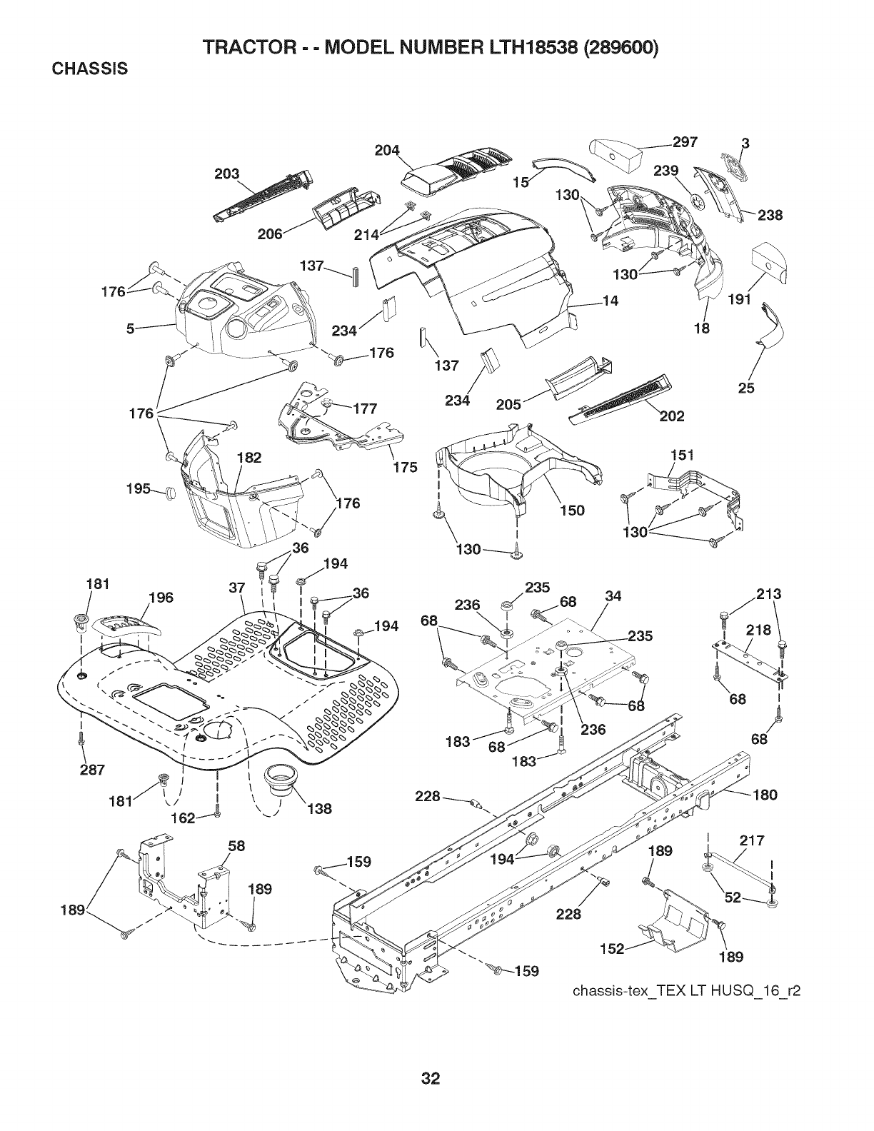
CHASSIS TRACTOR -- MODEL NUMBER LTH18538 (289600)
203
204
206
176
181 196
I
I
37 36
.194
58
189
\
137 /_
234 205
235
236
183 _
239
238
191
25
150
151
34
_235
236
68
228
I 217
189
\52
152 189
chassis-tex TEX LT HUSQ 16 r2
32

CHASSIS TRACTOR - - MODEL NUMBER LTH18538 (289600)
KEY
NO.
3
5
14
15
18
25
34
36
37
52
58
68
130
137
138
150
151
152
159
162
175
176
177
180
181
182
183
PART
NO.
532 40
532 40
532 41
532 41
532 42
532 41
532 19
817 06
532 41
873 68
532 41
817 49
532 41
532 40
532 40
532 40
532 40
532 19
817 00
532 14
532 19
532 40
532 19
532 41
532 40
532 40
874 52
50-12
75-92
10-73
10-79
69-63
10-78
61-25
05-12
63-07
05-00
22-80
05-08
63-58
75-90
29-54
66-62
78-07
95-35
06-12
24-32
94-72
07-76
52-28
50-63
30-25
71-76
05-20
KEY PART
DESCRIPTION NO. NO.
Logo 189 8170005-12
Dash 191 532 41 65-00
Hood 194 873 90 05-00
LensLH 195 53241 11-15
Grille 196 532 41 45-80
Lens RH 202 532 41 10-75
Plate Engine 203 532 41 10-74
Screw 5/16-18 x 3/4 204 532 41 11-16
Fender 205 532 41 10-76
Nut Crown Lock 5/16 206 532 41 10-77
Drawbar Upper 213 874 76 05-12
ScrewTHDROL5/16-18xl/2 214 532 19 91-45
Screw #10 x 0.750 BOS Thread 217 532 40 91-67
Bumper Dash 218 532 19 63-95
Cupholder 228 532 19 51-61
Air Duct 234 532 40 47-42
Bracket Pivot 235 532 40 61-29
Shield Browning 236 873 93 05-00
Screw Hexwash Thor 3/8-16 x 3/4 238 532 41 11-19
Screw 239 532 40 48-83
Crossmember Plate 287 817 60 04-06
Screw 10-24 x 5/8 297 532 40 66-65
Bushing Steering
Chassis
Bushing Mtg. Fender Crgo
Dash Lower
Bolt 5/16-18 x 1-1/4 Full Thd
DESCRIPTION
Screw 5/16-18 x 3/4
Insert Reflective RH
Nut Lock Hex Flange 5/16-18
Plug Dash
Console Asm. Deck Lift
Vent Side Hood RH
Vent Side Hood LH
Vent Top Hood
Skirt Side RH
Skirt Side LH
Bolt 5/16-18 x 3/4
Clip Retainer
Rod Pivot Hood
X-Piece Hood Stop
Stud Fastener
Bumper Hood
Spacer Fender
Nut Lock 5/16-18 unc
Trim
Clip Tinnerman
Screw Hex Washead 1/4-20 x 3/8
Insert reflective LH
NOTE: All component dimensions given in U.S. inches
1 inch = 25.4 mm
33
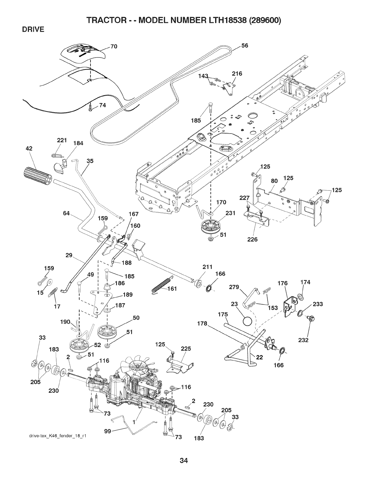
DRIVE TRACTOR -- MODEL NUMBER LTH18538 (289600)
216
42
221 184
35
185
167
170
231
227
226
125
/
29
159
17
33
183
205
230
drive-tex K46 fender 18 rl
125
211
166
/
_ 279 176 174
175
•232
166
230 205
33
183
34

DRIVE TRACTOR - - MODEL NUMBER LTH18538 (289600)
KEY PART
NO. NO.
2 532 12 35-83
15 819 13 13-16
17 532 41 36-78
22 532 19 78-60
23 532 14 08-45
29 532 40 38-06
33 812 00 00-01
35 532 40 10-31
42 532 12 48-72
49 872 11 08-14
50 532 19 43-27
51 873 90 08-00
52 532 19 43-28
58 532 13 09-89
84 532 19 82-00
70 532 41 14-74
73 874 49 05-44
74 532 14 24-32
80 532 41 00-24
99 532 41 57-42
116 873 90 05-00
125 817 00 05-12
143 817 49 05-08
153 532 12 47-88
159 878 02 04-12
180 532 18 94-84
161 532 10 57-09
188 532 42 91-84
KEY PART
DESCRIPTION NO. NO. DESCRIPTION
Transaxle, Tufftorq K46BA 167 532 40 52-57
(Internal Parts Not Available) 170 532 41 34-30
Key Square 174 532 19 72-89
Washer 13/32 x 13/16 x 16 Ga. 175 532 40 85-39
Spring, Brake 176 532 19 62-14
Rod Shift 178 532 19 74-56
Knob 183 532 13 70-57
Rod, Brake 184 532 40 97-47
RingE 185 8721106-22
Rod, Brake, Park 186 532 19 43-21
Cover, Foot Pedal 187 819 13 32-10
Bolt 188 532 19 43-23
Pulley Idler Flat 189 532 19 43-17
Lock Nut 3/8-16 190 532 19 43-18
Idler V-Groove 910" Offset 205 532 12 17-48
V-Belt, Drive 211 532 19 62-12
Shaft Asm. Pedal Brake Control 216 532 19 61-31
Console 221 532 40 31-87
Bolt Hex 5/16-18 Gr. 5 225 532 40 33-19
Screw 1/4 x 1/2 226 532 40 15-64
Strap Torque 227 817 49 05-12
Rod Spring Bypass 230 532 18 89-67
Nut Lock Hex Flange 5/16-18 231 532 40 72-87
Screw 5/16-18 x 3/4 232 874 78 07-16
Screw THDROL 5/16-18 233 532 40 52-96
Retainer Spring 1" 279 532 41 31-50
Pin Cotter 1/8 x 3/4
Retainer Clip
Spring, Return, Clutch
Nut Push
Latch Brake Parking
Keeper Belt Centerspan
Nut Push
Shaft Asm Shift
Arm Clevis Rod Shift
Spring Shift
Spacer Axle
Handle Parking Brake
Bolt
Spacer Retainer
Washer
Link Clutch Ground Drive
Bellcrank Ground Drive
Keeper Bellcrank Ground Drive
Washer 25/32 x 1-5/8 x 16 Ga.
Bushing Shaft
Bracket Pulley Idler
Retainer Spring Clip Handle
Keeper Belt Transaxle
Bracket Mount Torque
Screw 5/16-18 x 3/4
Washer Harden .793 x 1.637 x 060
Idler V-Groove 1.688" Offset
Bolt 7/16-14 x 1 Gr5
Washer Serrated
Link Shift
NOTE: All component dimensions given in U.S. inches
1 inch = 25.4 mm
35
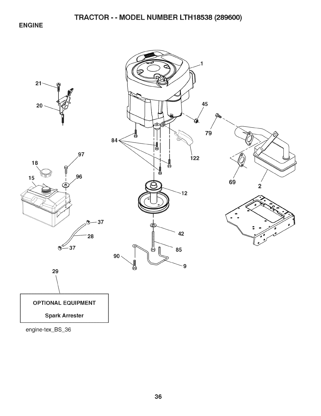
ENGINE TRACTOR -- MODEL NUMBER LTH18538 (289600)
21
18 7
15 _96
_--37
29
OPTIONAL EQUIPMENT
Spark Attester
engine-tex_BS_36
1
122
42
85
69 2
36

ENGINE TRACTOR - - MODEL NUMBER LTH18538 (289600)
KEY PART
NO. NO. DESCRIPTION
1 Engine Bnggs Model No.
31N707-1374-B1
2 532 13 73-52 Muffler
9 532 19 43-20 Keeper Belt Engine
12 532 40 54-71 Pulley Engine
15 532 40 75-45 Tank Fuel
18 532 43 02-20 Cap Fuel
20 532 18 38-97 Control Throttle/Choke
21 532 41 83-58 Screw #10 x 0.750 BOS Thread
28 532 40 11-37 Fuel Line
29 532 13 71-80 Spark Arrester Kit
37 532 12 34-87 Clamp Hose
42 810 04 07-00 Washer Lock 7/18
45 873 51 04-00 Nut Keps Hex 1/4-20 unc
69 532 16 52-91 Gasket
79 532 19 23-34 Screw 5/16-18 x 3/4
84 817 06 06-20 Screw 3/8-16 x 1/4
85 532 17 39-37 Bolt Hex 7/16-20 x 4 Gr. 5
90 8170006-18 Screw 3/8-16xl
98 819 09 14-18 Washer 9/32 x 7/8 x 18 Ga.
97 817 67 04-12 Screw 1/4-20 x 3/4
122 532 42 19-22 Extension Drain Oil
NOTE: All component dimensions given in U.S. inches
1 inch = 25.4 mm
For engine service and replacement parts, call the toll free
number for your engine manufacturer listed below:
Briggs & Stratton 1-800-233-3723
Engine Power Rating Information
The gross power rating for individual gas engine models is labeled in accordance with SAE (Society of Automotive En-
gineers) code J1940 (Small Engine Power & Torque Rating Procedure), and rating performance has been obtained and
corrected in accordance with SAE J1995 (Revision 2002-05). Torque values are derived at 3060 RPM; horsepower values
are derived at 3600 RPM. Actual gross engine power will be lower and is affected by, among other things, ambient operat-
ing conditions and engine-to-engine variability. Given both the wide array of products on which engines are placed and
the variety of environmental issues applicable to operating the equipment, the gas engine will not develop the rated gross
power when used in a given piece of power equipment (actual "on-site" or net power). This difference is due to a variety
of factors including, but not limited to, accessories (air cleaner, exhaust, charging, cooling, carburetor, fuel pump, etc.),
application limitations, ambient operating conditions (temperature, humidity, altitude), and engine-to-engine variability.
Due to manufacturing and capacity limitations, Briggs & Stratton may substitute an engine of higher rated power for this
Series engine.
37
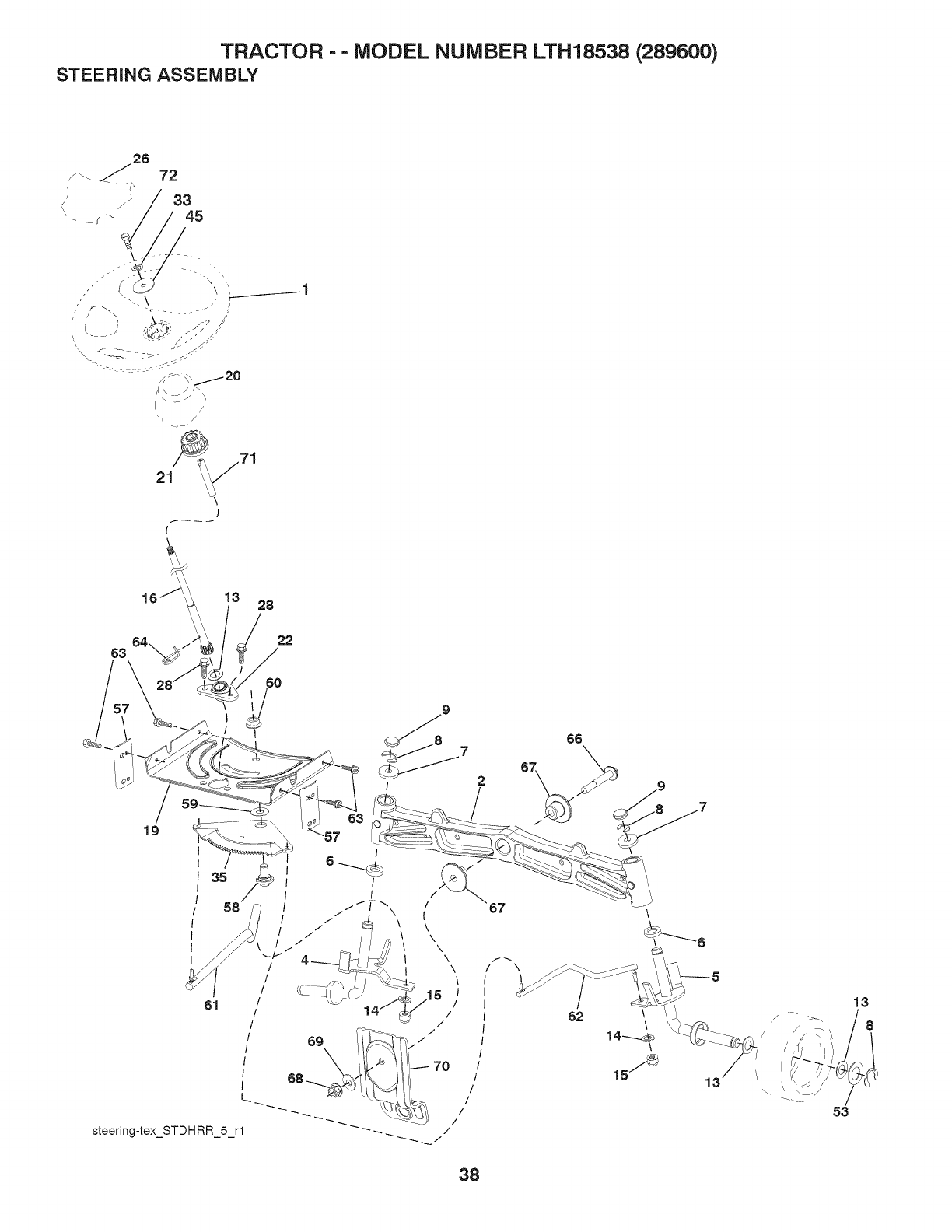
TRACTOR -- MODEL NUMBER LTH18538 (289600)
STEERING ASSEMBLY
/
63
i
16 13 28
19
9
766
\
steering-tex_STDHRR 5 rl _ /
62 \\
13
53
13
38

TRACTOR - - MODEL NUMBER LTH18538 (289600)
STEERING ASSEMBLY
KEY PART
NO. NO.
1 532 42 34-69
2 532 19 59-68
4 532 40 30-87
5 532 40 30-88
8 532 12 49-31
7 532 12 17-48
8 812 00 00-29
9 532 12 12-32
13 532 12 17-49
14 810 04 06-00
15 873 54 08-00
16 532 42 93-74
19 532 19 47-29
20 532 41 11-39
21 532 18 87-37
22 532 42 05-37
28 532 41 59-87
28 817 00 06-12
33 810 04 05-00
35 532 19 47-32
45 819 11 38-12
53 532 18 89-67
57 532 40 74-65
58 532 19 47-47
59 532 19 47-48
60 873 97 10-00
81 532 19 47-40
82 532 19 47-41
63 817 00 05-12
84 532 19 98-49
66 871 02 07-48
67 532 19 47-37
68 873 90 07-00
89 532 19 91-82
70 532 19 61-97
71 532 19 07-52
72 532 42 89-82
DESCRiPTiON
Wheel, Steering
Axle Asm., Front
Spindle Asm., LH
Spindle Asm., RH
Bearing, Race Thrust Harden
Washer 25/32 x 1-5/8 x 16 Ga.
Ring, Klip #T5304-75
Cap, Spindle
Washer 25/32 x 1-1/4 x 16 Ga.
Washer, Lock Hvy Hlcl Spr 3/8
Nut, Crown Lock 3/8-24 unf
Shaft Steering
Plate Steering
Boot Steering
Adapter, Wheel Steering
Strg. Supt. Lower
Insert, Wheel Steering
Screw 3/8-16 x 3/4
Washer Lock Hvy HLCL SPR. 5/16
Gear, Sector Plate
Washer 11/32 ID x 2 3/80D x 12 Ga.
Washer Hardened .793 x 1.637 x .060
Bracket Upstop
Bolt Shoulder Sector Pivot CFM
Washer Thrust Sector Steering
Nut Flange Lock 5/8-11
Draglink, LH
Draglink, RH
Screw 5/16-18 x 3/4
Retainer Clip Spring Steering
Bolt Hex Fghd 7/16-14 x 3 Serr
Bushing PM Front Axle
Nut Lock Flange 7/16-14 Gr. 5
Washer 1.5 x .505 x .118
Bracket Deck Susp. Front
Shaft Exten. Strg.
Bolt Fin Hx. 5/16-18 x 4 w/Patch
NOTE: All component dimensions given in U.S. inches
1 inch = 25.4 mm
39
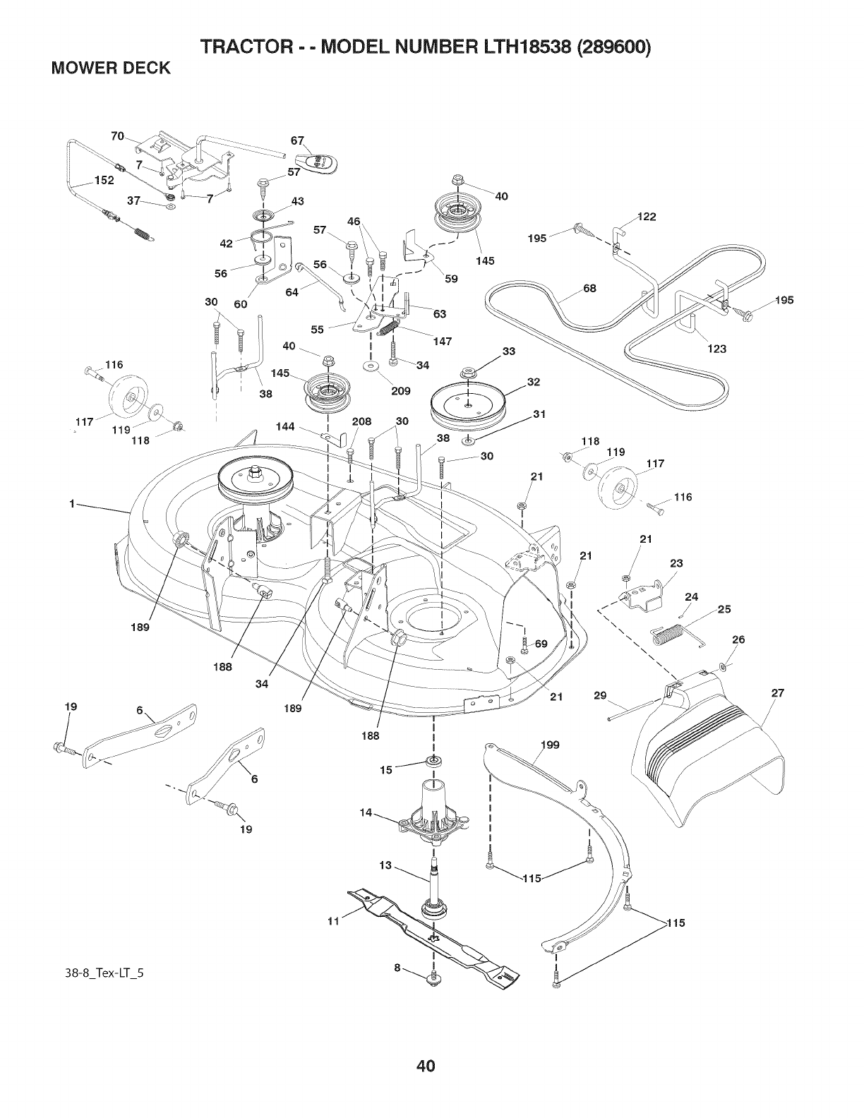
MOWER DECK TRACTOR -- MODEL NUMBER LTH18538 (289600)
118
19
I
21
34
189
21 29
199
/
\\
\\
123
....116
21
23
/
27
38-8_Tex-LT_5
19
11
4O

MOWER DECK TRACTOR - - MODEL NUMBER LTH18538 (289600)
KEY PART
NO. NO.
1 532 41 14-83
8 532 19 51-86
7 532 41 83-58
8 532 19 30-03
11 532 19 39-57
- - 532 13 84-97
13 532 19 28-72
14 532 18 72-81
15 532 11 04-85
19 532 19 85-39
21 873 68 05-00
23 532 19 25-57
24 532 10 53-04
25 532 19 70-28
28 532 11 04-52
27 532 19 39-88
29 532 13 14-91
30 532 17 39-84
31 532 18 78-90
32 532 19 97-89
33 532 40 02-34
34 872 11 08-12
37 819 13 13-18
38 532 19 95-41
40 873 90 06-00
42 532 19 84-10
43 532 19 72-56
48 532 13 77-29
55 532 19 72-49
58 532 19 90-92
57 817 00 08-18
59 532 14 10-43
KEY PART
DESCRIPTION NO. NO. DESCRIPTION
Mower Housing
Arm Suspension
Screw #10 x 0.750 BOS Thread
Bolt/Washer asm 7/18-20 unf
Blade 38" 3N1 PREMIUM
Blade 38" HI PERF
Shaft Assembly, Mandrel
Housing, Mandrel
Bearing, Ball, Mandrel
Bolt, Shoulder
Nut, Crownlock 5/18-18 unc
Bracket, Deflector
Cap, Sleeve
Spring, Torsion, Deflector
Nut, Push
Shield, Deflector
Rod, Hinge
Screw Thdrol Rolling Wsh Hd
Washer, Spacer
Pulley, Mandrel
Nut, Toplock, Flanged
Bolt Carr Sh. 3/8-18 x 1-1/2 Gr. 5
Washer
Keeper Belt LH Mandrel
Nut, Lock Fig. 3/8-18 unc
Spring Torsion Brake
Spring Torsion Retainer
Screw 1/4-20 x 5/8
Arm, Idler
Spacer, Retainer
Screw 3/8-16 x 1
Guard, Tuv Idler
60 532 19 94-71 Arm Brake Mower LH
83 532 19 94-70 Arm Brake Mower RH
84 532 19 99-18 Link Brake
87 532 40 30-12 Handle Clutch Cable
68 532 40 83-81 V-Belt
89 872 14 05-05 Bolt
70 532 40 12-48 Clutch Asm Manual
115 8721105-05 BoltCarr. 5/18-18 x 5/8
116 532 12 48-42 Bolt, Shoulder
117 5321888-08 Wheel, Gauge
118 873 93 08-00 Nut Lock 3/8-18unc
119 819 12 14-14 Washer 3/8 x 7/8 x14 Ga.
122 532 19 72-58 Keeper Belt Engine LH
123 532 19 72-59 Keeper Belt Engine RH
144 532 19 34-14 Keeper Belt
145 532 19 31-97 Pulley Idler
147 532 40 18-72 Spring Return
152 532 43 51-11 Manual Clutch Cable
188 532 19 51-81 Stud Fastener
189 873 90 05-00 Nut Lock Hex Flange
195 8170008-12 Screw 3/8-18x3/4
199 532 40 00-95 Baffle Vortex
208 817 87 08-08 Screw Thdrol 3/8-18 x 1/2
209 819 13 32-10 Washer 13/32x2x 10
- - 532 19 28-70 Mandrel Assembly (Includes hous-
ing, shaft assembly, and bearing
only - pulley/nut/washer and blade
bolt/washers not included)
- - 532 41 07-16 Replacement Mower, Complete
NOTE: All component dimensions given in U.S. inches
1 inch = 25.4 mm
41
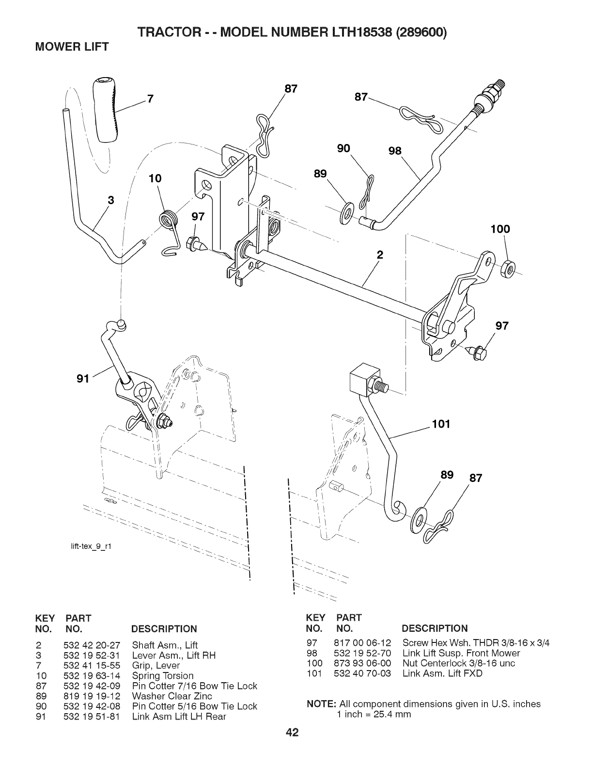
MOWER LIFT TRACTOR -- MODEL NUMBER LTH18538 (289600)
87
3
/10 89
90
2
100
KEY
NO.
2
3
7
10
87
89
9O
91
91
PART
NO. DESCRiPTiON
532 42 20-27
532 19 52-31
532 41 15-55
532 19 63-14
532 19 42-09
819 19 19-12
532 19 42-08
532 19 51-81
Shaft Asm., Lift
Lever Asm., Lift RH
Grip, Lever
Spring Torsion
Pin Cotter 7/16 Bow Tie Lock
Washer Clear Zinc
Pin Cotter 5/16 Bow Tie Lock
Link Asm Lift LH Rear
97
101
KEY PART
NO. NO.
97 817 00 06-12
98 532 19 52-70
100 873 93 06-00
101 532 40 70-03
DESCRiPTiON
Screw Hex Wsh. THDR 3/8-16 x 3/4
Link Lift Susp. Front Mower
Nut Centerlock 3/8-16 unc
Link Asm. Lift FXD
NOTE: All component dimensions given in U.S. inches
1 inch = 25.4 mm
42
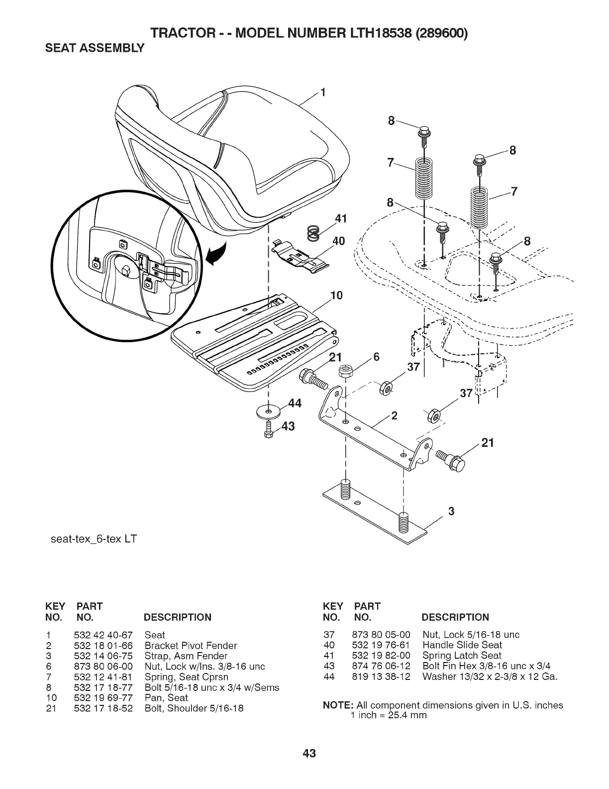
TRACTOR - - MODEL NUMBER LTH18538 (289600)
SEAT ASSEMBLY
21
seat-tex_6-tex LT
3
KEY PART
NO. NO.
1 532 42 40-67
2 532 18 01-68
3 532 14 06-75
6 873 80 08-00
7 532 12 41-81
8 532 17 18-77
10 532 19 69-77
21 532 17 18-52
DESCRIPTION
Seat
Bracket Pivot Fender
Strap, Asm Fender
Nut, Lock w/Ins. 3/8-16 unc
Spring, Seat Cprsn
Bolt 5/16-18 unc x 3/4 w/Sems
Pan, Seat
Bolt, Shoulder 5/16-18
KEY PART
NO. NO.
37 873 80 05-00
40 532 19 76-61
41 532 19 82-00
43 874 76 06-12
44 819 13 38-12
DESCRIPTION
Nut, Lock 5/16-18 unc
Handle Slide Seat
Spring Latch Seat
Bolt Fin Hex 3/8-16 unc x 3/4
Washer 13/32 x 2-3/8 x 12 Ga.
NOTE: All component dimensions given in U.S. inches
1 inch = 25.4 mm
43
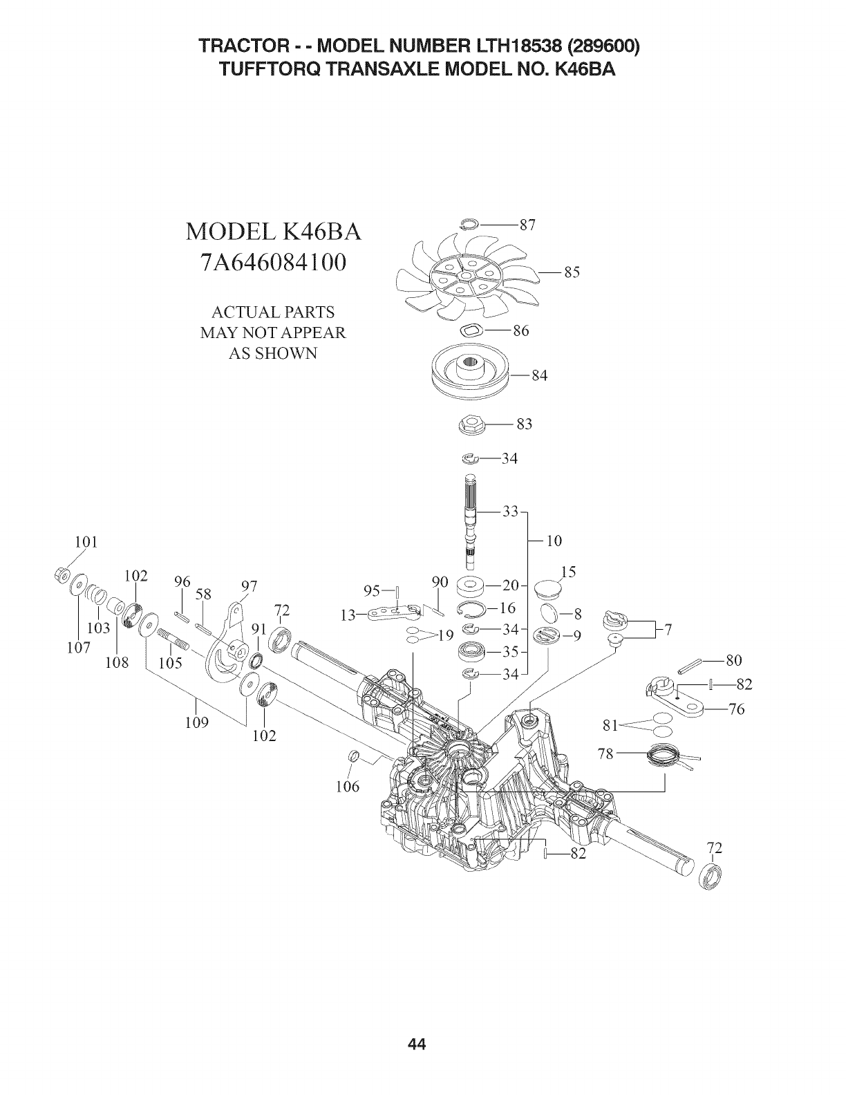
TRACTOR - - MODEL NUMBER LTH18538 (289600)
TUFFTORQ TRANSAXLE MODEL NO. K46BA
101
/102
I96 58
107
10g 105
MODEL K46BA
7A646084100
ACTUAL PARTS
MAY NOT APPEAR
AS SHOWN
_m87
i _/_-'_
_--s6
--84
_83
97
72
I
Om34
_m34
lO9 102
106
72
I
44

TRACTOR -- MODEL NUMBER LTH18538 (289600)
TUFFTORQ TRANSAXLE MODEL NO. K46BA
KEY PART
NO. NO. DESCRiPTiON
7 532 41 43-95 Vent Valve 15
8 532 41 43-96 Magnet
9 532 41 43-97 Magnet Holder
10 532 41 59-23 Pump Shaft/Bearing Kit
13 532 41 43-98 Bypass Lever
15 532 41 43-99 Sealing Cap 30
16 532 41 44-00 Snap Ring C 35
19 532 41 44-01 O-Ring la P10a
20 532 41 44-02 Seal Tc 153507
33 532 41 44-03 Pump Shaft (Standard
34 532 41 44-04 E-Ring 15
35 532 41 44-05 Bearing 6202c3
58 532 41 44-08 Roll Pin 8"40
72 532 41 44-07 Seal 19"32"8
78 532 41 44-08 Brake Lever
78 532 41 44-09 Brake Return Spring
80 53241 44-10 SpringPin 5*32
81 532 41 44-11 O-Ring 1aP12
82 53241 44-12 Spring Pin 4"18
83 532 41 44-13 Spine Collar
84 532 41 44-14 Pulley L
85 532 41 44-15 Fan, Black
88 532 41 44-18 Wave Washer
87 532 41 44-17 Snap Ring
90 53241 44-18 SpringPin 3.0a'20
91 532 41 44-19 Oil Seal 18"22"03
95 532 41 58-50 Spring Pin 3.0a* 16
96 532 41 44-20 Roll Pin 3.5"40
97 532 41 44-21 Control Lever
101 532 41 42-16 Lock Nut 10
102 532 41 44-23 Washer 10"40"4
103 532 41 44-24 Spring
105 532 41 44-25 Stud 10"80
108 532 41 44-28 Sealing Cap 18
107 532 41 44-27 Washer 10"36"2.8
108 532 41 44-28 Collar 10"20"17
109 532 41 44-29 Friction Plate Kit
NOTE: All component dimensions given in U.S. inches
1 inch = 25.4 mm
45
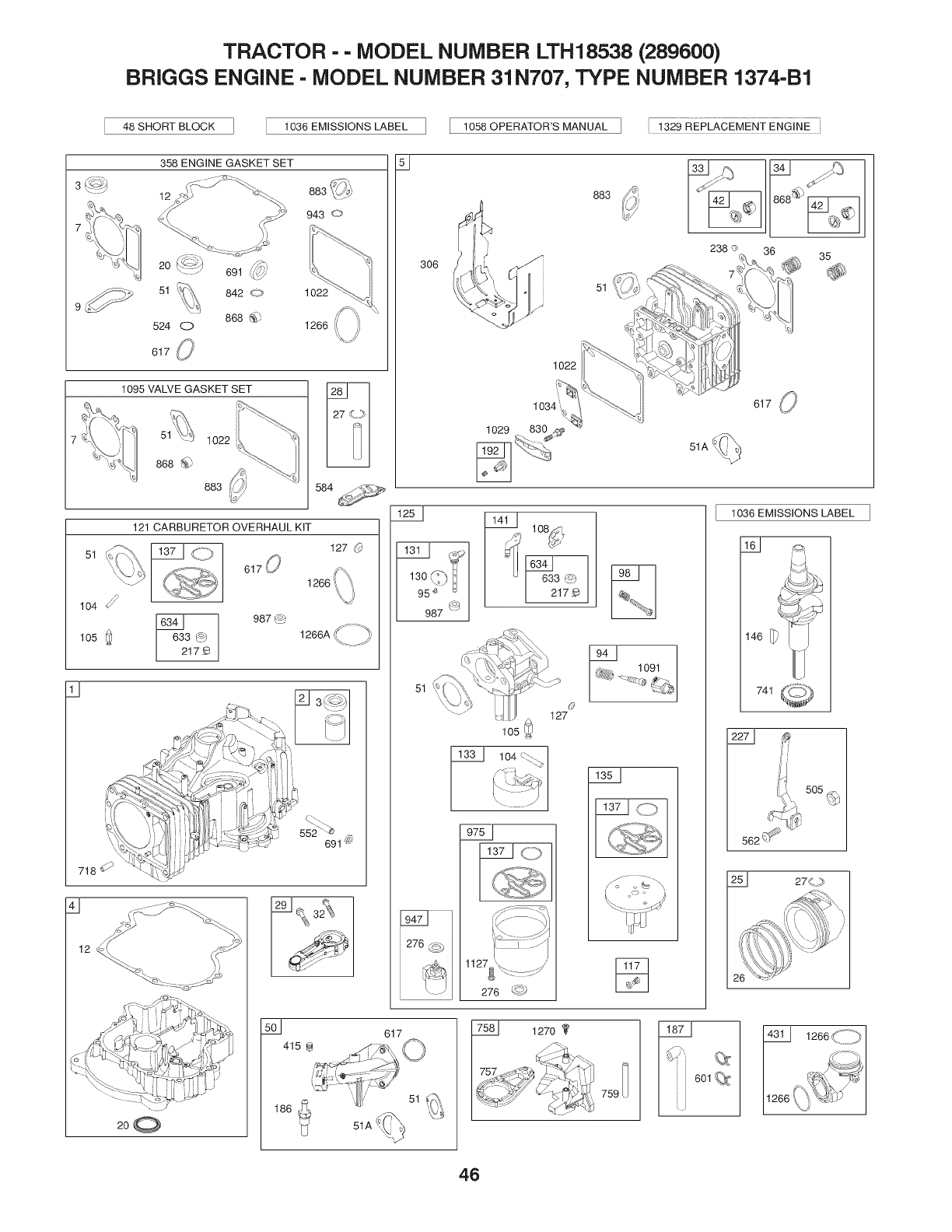
TRACTOR --MODEL NUMBER LTH18538 (289600)
BRIGGS ENGINE - MODEL NUMBER 31 N707, TYPE NUMBER 1374-B1
48 SHORT BLOCK 1036 EMISSIONS LABEL 1058 OPERATOR'S MANUAL I , 132_gREPLACEMENT ENGINE
51
358 ENGINE GASKET SET
l,
12
104
105 Q
11
943 _>
1095 VALVE GASKET SET
1022
'/
1266 i( ,,i)
1022
868 _
883
121 CARBURETOR OVERHAUL KIT
584 -,_
127
1266 (
3_
17_
987 _
1266A_ -'_
718
200
552 691 _
306
125{ 1141I 108,<_q
I/_;_ G_
13o_I) I _1 633_)
95e /I 21z_
987 _
51
lO5
104
276 _4.,'
©
127
617
883
51
1091
%
759
238 ® 36 35
617 (_
51A
1036 EMISSIONS LABEL
146 _') _
741
601
1266<_
[126641266,t_'_'@/J
46

TRACTOR -- MODEL NUMBER LTH18538 (289600)
BRIGGS ENGINE - MODEL NUMBER 31 N707, TYPE NUMBER 1374-B1
3o_
643
967
1005
5240
334
851
54% 654:#
12
222
306
309
510_1051 =' 801
783
513
462
579
544
616
1023_ 1022
5
305
lO4O,,,%. ,,_' ,o5,_+
37 .:::_ i
1044
15 _ 22 85O
404 # 684
614 [l 1044
47

TRACTOR --MODEL NUMBER LTH18538 (289600)
BRIGGS ENGINE - MODEL NUMBER 31 N707, TYPE NUMBER 1374-B1
KEY PART
NO. NO.
1 796010
2 399265
3 • 391086s
4 697106
5 796025
7 ._ 796584
11 794683
12 • 697110
13 793988
15 690946
16 797579
20 • 795387
22 692125
23 698281
24 222698s
25 796172
796173
26 791936
792649
27 698469
28 796007
29 794122
32 791118
33 792868
34 791935
35 691279
36 691279
37 697352
42 499586
43 691968
45 690564
46 793880
48 697761
50 796180
51._4" 692137
51A 796081
53 690227
54 691148
78 691003
94 793610
95 690718
98 695408
104 4"694918
105 4"696136
108 695419
117 843099
118 790890
121 796184
125 796109
127 4" 690727
130 699500
KEY PART
DESCRIPTION NO. NO.
Cylinder Assembly 131 699501
Bushing/SeaIKit 133 694914
(Magneto Side) 135 698780
Seal-Oil (Magneto Side) 137 4, 698781
Sump-Engine 141 792777
Head-Cylinder 146 691639
Gasket-Cylinder Head 186 794873
Tube-Breather 187 791805
Gasket-Crankcase
Screw (Cylinder Head) 188 691693
Plug-Oil Drain 192 691986
Crankshaft 202 691841
Seal-Oil (PTO Side) 209 692208
Screw (Crankcase Cover/Sump) 216 691840
Flywheel 217 695409
Key-Flywheel 222 694042
Piston Assembly (Standard) 227 691374
Piston Assembly (.020" 232 691842
Oversize) 238 691843
Ring Set (Standard) 240 394358s
Ring Set (.020" Oversize) 265 691024
Lock-Piston Pin 267 794904
Pin-Piston 276 695410
Rod-Connecting 304 796416
Screw (Connecting Rod) 305 697102
Valve-Exhaust 305A 793376
Valve-Intake 306 796006
Spring-Valve (Intake) 307 691003
Spring-Valve (Exhaust) 309 693551
Guard-Flywheel 310 690323
Keeper-Valve 324 796308
Slinger-Governor/Oil 333 795315
Tappet-Valve 334 691061
Gear-Cam 337 491055s
Short Block 358 796187
Manifold-Intake 404 691691
Gasket-Intake 415 690283
Gasket-Intake 415A 794129
Stud (Carburetor) 431 697122
Screw (Intake Manifold) 445 698083
Screw (Flywheel Guard) 462 691261
Kit-Idle Mixture 474 696459
Screw (Throttle Valve) 503 691532
Kit-Idle Speed 505 691251
Pin-Float Hinge 510 693699
Valve-Float Needle 513 692024
Valve-Choke 523 699908
Jet-Main (Standard) 524 • 691032
Jet-Main (High Altitude) 525 697184
Kit-Carburetor Overhaul 544
Carburetor
Plug-Welch
Valve-Throttle 552 697144
DESCRIPTION
Kit-Throttle Shaft
Float-Carburetor
Tube-Fuel Transfer
Gasket-Float Bowl
Kit-Choke Shaft
Key-Timing
Connector-Hose(Intak Manifold)
Line-Fuel (Formed) (Cut to
Required Length)
Screw (Control Bracket)
Adjuster-Rocker Arm
Link-Mechanical Governor
Spring-Governor (Green)
Link-Choke
Spring-Choke Return
Bracket-Control
Lever-Governor Control
Spring-Governor Link
Cap-Valve
Filter-Fuel
Clamp-Casing
Screw (Casing Clamp)
Washer-Sealing
Blower Housing
Screw (Blower Housing) (Long)
Screw (Blower Housing) (Short)
Shield-Cylinder
Screw (Cylinder Shield)
Motor-Starter
Screw (Starter Motor)
Screen/Cup Assembly
Armature-Magneto
Screw (Magneto Armature)
Plug-Spark
Gasket Set-Engine
Washer (Governor Crank)
Plug (Intake Manifold)
Plug (Cover/Retainer)
Elbow-Intake
Filter-Air Cleaner Cartridge
Washer (Starter Cable)
Alternator
Strap-Starter
Nut (Governor Control Lever)
Drive-Starter
Clutch-Drive
Dipstick
Seal-Dipstick Tube
Tube-Dipstick
Armature-Starter (Order Starter
Motor, Reference 309,693551,
for replacement)
Bushing-Governor Crank
48
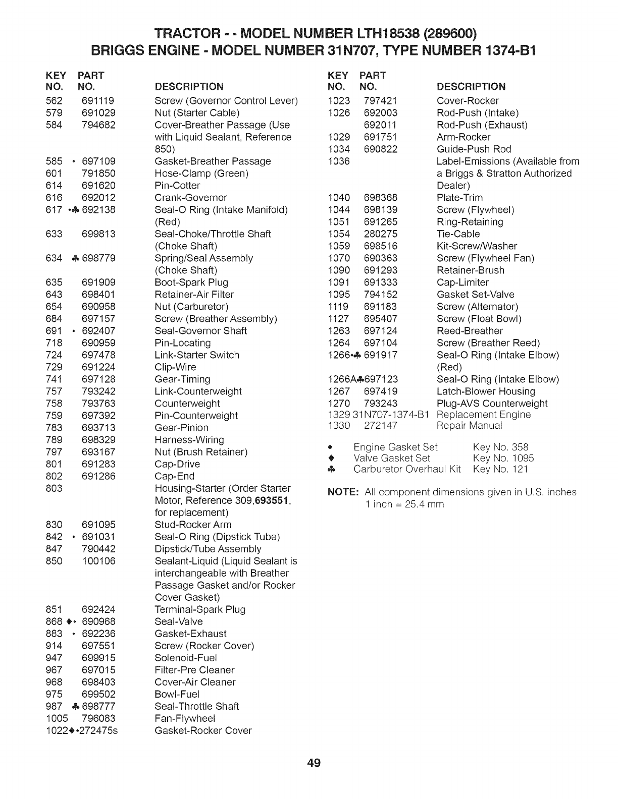
TRACTOR -- MODEL NUMBER LTH18538 (289600)
BRIGGS ENGINE - MODEL NUMBER 31 N707, TYPE NUMBER 1374-B1
KEY PART
NO. NO.
562 691119
579 691029
584 794682
585 • 697109
601 791850
614 691620
616 692012
617 .& 692138
633 699813
634 _698779
635 691909
643 698401
654 690958
684 697157
691 • 692407
718 690959
724 697478
729 691224
741 697128
757 793242
758 793763
759 697392
783 693713
789 698329
797 693167
801 691283
802 691286
803
830 691095
842 • 691031
847 790442
850 100106
851 692424
868 _. 690968
883 • 692236
914 697551
947 699915
967 697015
968 698403
975 699502
987 _698777
1005 796083
1022_.272475s
KEY PART
DESCRiPTiON NO. NO.
Screw (Governor Control Lever) 1023 797421
Nut (Starter Cable) 1026 692003
Cover-Breather Passage (Use 692011
with Liquid Sealant, Reference 1029 691751
850) 1034 690822
Gasket-Breather Passage 1036
Hose-Clamp (Green)
Pin-Cotter
Crank-Governor 1040 698368
SeaI-O Ring (Intake Manifold) 1044 698139
(Red) 1051 691265
Seal-Choke/Throttle Shaft 1054 280275
(Choke Shaft) 1059 698516
Spring/Seal Assembly 1070 690363
(Choke Shaft) 1090 691293
Boot-Spark Plug 1091 691333
Retainer-Air Filter 1095 794152
Nut (Carburetor) 1119 691183
Screw (Breather Assembly) 1127 695407
Seal-Governor Shaft 1263 697124
Pin-Locating 1264 697104
Link-Starter Switch 1266.4. 691917
Clip-Wire
Gear-Timing
Link-Counterweight
Counterweight
Pin-Counterweight
Gear-Pinion
Harness-Wiring o
Nut (Brush Retainer) _,
Cap-Drive
Cap-End
Housing-Starter (Order Starter
Motor, Reference 309,693551,
for replacement)
Stud=Rocker Arm
SeaI-O Ring (Dipstick Tube)
Dipstick/Tube Assembly
Sealant-Liquid (Liquid Sealant is
interchangeable with Breather
Passage Gasket and/or Rocker
Cover Gasket)
Terminal=Spark Plug
Seal-Valve
Gasket-Exhaust
Screw (Rocker Cover)
Solenoid=Fuel
Filter-Pre Cleaner
Cover-Air Cleaner
Bowl-Fuel
Seal-Throttle Shaft
Fan=Flywheel
Gasket-Rocker Cover
1266A_697123
1267 697419
1270 793243
1329 31N707-1374-B1
1330 272147
DESCRiPTiON
Cover-Rocker
Rod-Push (Intake)
Rod-Push (Exhaust)
Arm-Rocker
Guide=Push Rod
Label-Emissions (Available from
a Briggs & Stratton Authorized
Dealer)
Plate=Trim
Screw (Flywheel)
Ring-Retaining
Tie-Cable
Kit-Screw/Washer
Screw (Flywheel Fan)
Retainer-Brush
Cap-Limiter
Gasket Set-Valve
Screw (Alternator)
Screw (Float Bowl)
Reed-Breather
Screw (Breather Reed)
SeaI-O Ring (Intake Elbow)
(Red)
SeaI-O Ring (Intake Elbow)
Latch-Blower Housing
Plug-AVS Counterweight
Replacement Engine
Repair Manual
Engine Gasket Set Key No. 358
Valve Gasket Set Key No. 1095
Carburetor Overhaul Kit Key No. 121
NOTE: All component dimensions given in U.S. inches
1 inch -- 25.4 mm
49

SUGGESTED GUIDE FOR SIGHTING SLOPES FOR SAFE OPERATION
O1
O
ONLY RIDE UP AND DOWN HILL,
NOT ACROSS HILL
15 DEGREES MAX.
_ARNING: To avoid serious injury, operate your tractor up and
down the face of slopes, never across the face. Do not mow
slopes greater than 15 degrees. Make turns gradually to prevent
tipping or loss of control. Exercise extreme caution when
changing direction on slopes.
1. Fold this page along dotted line indicated above.
2. Hold page before you so that its left edge is vertically parallel to atree
trunk or other upright structure.
3. Sight across the fold in the direction of hill slope you want to measure.
4. Compare the angle of the fold with the slope of the hill.

Husqvarna
Consumer Wheeled Products - Limited Warranty
Husqvarna warrants to the original retail purchaser that this Husqvarna{R} product is free from defects in material or workmanship
under normal use and maintenance ti_omthe date of retail purchase tbr the applicable Warranty Period shown on Exhibit A. Certain
components (e.g., engines and transmissions) are excluded from coverage, and other limitations apply, as described in this document.
Husqvarna will repair or replace at its discretion, any detective product or part covered by the Limited Warranty, tree of charge at any
authorized Husqvarna Servicing Dealer/Center using original OEM Husqvarna replacement parts, suIzject to the limitations and
exclusions described below. Husqvarna does not offer an over-the-counter exchange program.
THIS LIMITED WARRANTY IS THE SOLE EXPRESS WARRANTY PROVIDED BY HUSQVARNA. ANY WARRANTY
THAT MAY BE IMPLIED BY LAW (INCLUDING ANY IMPLIED WARRANTY OF FITNESS FOR A PARTICULAR
PURPOSE OR USE AND IMPLIED WARRANTY OF MERCHANTABILITY) IS LIMITED TO THE DURATION OF THE
APPLICABLE WARRANTY PERIOD UNDER THIS LIMITED WARRANTY. THIS LIMITED WARRANTY MAY BE
MODIFIED ONLY BY HUSQVARNA. SOME STATES DO NOT ALLOW LIMITATIONS ON HOW LONG AN IMPLIED
WARRANTY LASTS, SO THE ABOVE LIMITATIONS MAY NOT APPLY TO YOU. THIS LIMITED WARRANTY GIVES
YOU SPECIFIC LEGAL RIGHTS, AND YOU MAY ALSO HAVE OTHER RIGHTS WHICH VARY FROM STATE TO STATE.
THIS WARRANTY IS GIVEN ONLY BY HUSQVARNA. THE ABOVE REMEDIES ARE THE EXCLUSIVE REMEDIES FOR
ANY BREACH OF THIS LIMITED WARRANTY. HUSQVARNA AND ITS AFFILIATED COMPANIES SHALL NOT BE
LIABLE FOR ANY SPECIAL, INCIDENTAL OR CONSEQUENTIAL DAMAGE, INCLUDING LOST PROFITS RESULTING
FROM ANY SUCH BREACH, AND ALL SUCH DAMAGES ARE HEREBY DISCLAIMED. SOME STATES DO NOT ALLOW
THE EXCLUSION OR LIMITATION OF INCIDENTAL OR CONSEQUENTIAL DAMAGES, SO THE ABOVE LIMITATIONS
MAY NOT APPLY TO YOU.
LIMITATIONS AND EXCLUSIONS
1. Engines, Transmissions and certain other components are NOT covered. This Limited Warranty does not cover any of the
t_dlowing:
(a) Engines and Attachments. Except where otherwise indicated on Exhibit A, all Engines and Attachments are not covered by
this warranty. In most cases, these items are NOT manufactured by Husqvarna in which case they may be covered separately by
their respective manufacturer's warranties if one is provided and included with the product at the time of purchase. All such
claims nmst be submitted and sent to the appropriate manufacturer or as otherwise directed in those separate warranties.
Husqvarna is not authorized to handle warranty adjustments or repairs on engines manufactured by Briggs & Stratton, Honda,
Kawasaki, or Kohler (exception - models equipped with LCT engines). Husqvarna does not assume any warranty obligation of
the other manufacturer's engines.
(b) Transmissions. Except where otherwise indicated on Exhibit A, Transmission /Transaxle (including Drive Systems) are not
covered by this warranty. In most cases, these items are NOT manufactured by Husqvarna in which case they may be covered
separately by their respective manufacturer's warranties if one is provided and included with the product at the time of purchase.
The t_dlowing transmission /transaxle manufacturers, Dana, Hydro-Gear, Tuff-Torq provide a warranty tbr the transmission /
transaxle to the ultimate purchaser or to Husqvarna. Husqvarna will assign the transmission /transaxle manufacturer's warranty
or any rights thereof to the original purchaser of the unit. To obtain transmission /transaxle warranty service, first contact the
retailer who you purchased the unit from. Should you require assistance or have any questions concerning transmission /transaxle
warranty coverage, contact Husqvarna directly at our website www.husqvarna.com or call 800-487-5951 tbr an authorized
Husqvarna service provider. All such claims must be submitted and sent to the appropriate manufacturer or as otherwise directed
in those separate warranties. Husqvarna is not authorized to handle warranty adjustments or repairs on transmissions or transaxles.
Husqvarna does not assume any warranty obligation of the above listed manufacturers (t_r exceptions - see Exhibit A).
(c) Expendable Parts. This Limited Warranty does not cover general maintenance parts and items ("Expendable Parts"),
including without limitation spark plugs, bulbs, filters, lubricants, starter cords, belts, blades, and blade adapters.
(d) Emissions (Untrol (Umponents. This Limited Warranty does not cover Emissions control equipment and components to the
extent regulated by the U.S. Environmental Protection Agency or similar state agencies. Such equipment and components are
covered by a separate emission control warranty statement supplied with your new product. Please consult this separate warranty
statement lZ_rdetails.
2. An)' COMMERCIAL, INSITUTIONAL, AGRICULTURAL INDUSTRIAL, INCOME PRODUCING, or RENTAL use will result in either No
Warranty or a Shortened Warranty Period Depending on the product; there is either NO WARRANTY or a reduced warranty if the product is used fk)r commercial,
institutional, agricultural, industrial, income producing, or rental purposes. Please refer to Exhibit A.
3. Owner's (Your) Responsibilities. To preserve your rights under this Limited Warranty, you nmst demonstrate reasonable care
and use of the product, including, t_)llowing the preventative maintenance, storage, fi_el and oil usages as prescribed in the enclosed
operator's manual. For example, the tbllowing items are the Owner's responsibility and are no_tcovered by this Limited Warranty:
a. Set-up and pre-delivery service, and engine tune-ups.
b. Adjustments after the first (30) thirty days of purchase and beyond, such as throttle cable, belt guides adjustments.
51
c. Preventative maintenance as outlined in the operator's mamml.
In addition, you nmst cease using the product immediately upon any failure or damage. The product should be taken to an authorized
Husqvarna servicing dealer prior to any fi_rther use.
4. Damages resulting from normal aging, wear and tear or neglect are NOT covered. The Limited Warranty does not cover
damage other than that resulting from detects in material or workmaanship. The lbllowing are NOT considered detects in material or
workmaanship, and therefore are NOT covered.
(a) Abrasion to mower decks;
(b) Tires damaged by external punctures;
(c) Natural discoloration of materials due to ultraviolet light;
(d) Damage to cutting equipment by way of contact with, rocks, or other non-approved materials and/or structures;
In addition, this Limited Warranty does not cover damages, malfunctions or failures resulting from abuse or neglect of the product
related to or including any of the lbllowing:
(e) Failure to provide or perlbrm required maintenance services as prescribed in the operator's manual;
(t) Abuse, misuse, neglect, modifications, alterations, normal wear, improper servicing, use of unauthorized attachments, Lack of
lubrication or engine failure, due to the use of oils that do not meet Engine manufacturer's specifications;
(g) Use of gasohol, containing methanol (wood alcohol). Gasohol which contains a naaxinmm 10% ethanol (grain alcohol) or
15% MTBE (naethyl/tertiary/butyl/ether) is approved;
(h) Use of ether or any starting fluids;
(i) Pressure cleaning or steam cleaning the product;
(i) Use of spark plugs other than those meeting emission performance requirements listed in the operator's mamml;
(k) Tampering with engine speed governor or emission components, or rtmning engines above specified and recommended
engine speeds as listed in your operator's manual;
(1) Operation of the unit with improperly installed/removed or modified cutting shields, guards, or safety devices;
(m) Any removed/damaged air filter, excessive dirt, abrasives, salt water, moisture, corrosion, rust, varnish, stale fi_el, or any
adverse reaction due to incorrect storage procedures;
(n) Failures due to improper set up, pre-delivery service or repair service by anyone other than an authorized Hnsqvarna
servicing dealer during the warranty period;
(o) Dirt contaminated grease or oil, use of incorrect type of greases or oils, failure to comply with recommended greasing
intervals, water or moisture damage, and/or improper storage;
(p) Sprayers pumping or spraying caustic or flammable materials, lack of or broken strainers; or
(q) Continued use of product, alter initial operational problem or failure occurs.
HOW TO OBTAIN SERVICE
5. Authorized Husqvarna Servicing Dealer/Center. In order to obtain warranty coverage it is your responsibility (at your
expense) to deliver or ship your Husqvarna unit to an authorized Husqvarna Servicing Dealer/Center and arrange for pick-up or return
of your unit alter the repairs have been made. If you do not lcnow the location of your nearest authorized Husqvarna Servicing Dealer,
call Husqvarna, at 1-800-487-5951 during the hours of 8:00 AM to 8:00 PM Eastern Standard Time, or visit www.husqvarna.com.
Should you require assistance or have questions concerning this Limited Warranty, you may contact us at 800-487-5951 during the
hours of 8:00 AM to 8:00 PM Eastern Standard Time or contact us through the web at www.husqvarna.com.
6. Documentation Required. You must maintain and present Proof of purchase (including date, product model and, if applicable,
engine serial number) to an authorized Husqvarna Servicing Dealer for warranty service under this Limited Warranty. Proof of
purchase rests solely with the owner-customer. Hnsqvarna encourages you to register your product online at
www.usa.husqvama.com to help ensure, among other things, that you can be notified of important product information. However,
registering your product is not a condition of warranty service.
Husqvarna ('onxumer Outdoor Products N.A., Inc.," Husqvarna Pr@s'sional Products, Inc.
9335 Harris (_rnen_ Parkwm' Charlotte, N(" 28269
575 49 43-01 R3 2010
52

Exhibit A
Consumer Wheeled Warranty Chart 2010
Consumer (personal,
household use only)
5 Years
3 Years
1 Year Pro-rated
3 Years
1 Year Pro-rated
3 Years
1 Year Pro-rated
3 Years
2 Years
1 Year Pro-rated
2 Years
2 Years
Commercial (any commercial,
professional, institutional,
arigculutral, or income producing
use, other than Rental Use)
Product/Component
Ridin _wn rs :
Frame, Chassis, Front Axle
Engine*
Transmission (if made by
Husqvama/Peerless)
Transmission (if third party)**
Battery
Other Non-Expendable Components
_ _ ti#:!Z#ro Turn Mo_:rs
Engine*
Transmission **
Battery
Other Non-Expendable Components
#_i__tim i _ro::: Turn Mo _ _rs EZ):
Engine*
Transmission **
Battery
Other Non-Expendable Components
E4 _ Edge::
Engine*
Other Non-Expendable Components
Elk B_ _ Mo_rs
Engine*
Battery
Other Non-Expendable Components
S_Thro _rs:
Engine*
Other Non-Expendable Components
Til_rs
Engine*
Battery
Other Non-Expendable Components
Tiller Tines
_ _rin_ _rs
Engine*
Other Non-Expendab e Components
1 Year Pro-rated
2 Years
NO WARRANTY
NO WARRANTY
NO WARRANTY
NO WARRANTY
NO WARRANTY
NO WARRANTY
1 Year Pro-rated
1 Year
90 days
NO WARRANTY
NO WARRANTY
90 days
NO WARRANTY
NO WARRANTY
NO WARRANTY
Rental (any rental
usage)
NO WARRANTY
NO WARRANTY
NO WARRANTY
NO WARRANTY
NO WARRANTY
NO WARRANTY
NO WARRANTY
NO WARRANTY
NO WARRANTY
90 days
NO WARRANTY
NO WARRANTY
90 days
NO WARRANTY
NO WARRANTY
NO WARRANTY
2 Years 1 Year 90 days
Consumer Commercial Rental
* See Separate Engine Manufacturer's or Manufacturer's warranty
LCT Engines on specific Snow Throwers & Tillers, warranty through Husqvarna.
** See reference 1 (b) of the warranty statement.
RZ - Two (2) Year Consumer warranty, parts & labor, with Hydro-Gear Distributor network.
EZ - One (1) Year Commercial warranty, parts & labor, with Husqvarna.
Two (2) Year Consumer warranty, parts & labor, with Hydro-Gear Distributor network.
MZ - Two (2) Year Commercial warranty, parts & labor, with Hydro-Gear Distributor network.
..... Limited Lifetime Warranty" on Tiller tines is for the life of the product or 7 (seven) years after the last date of the complete
unit's final production, whichever comes first.
53
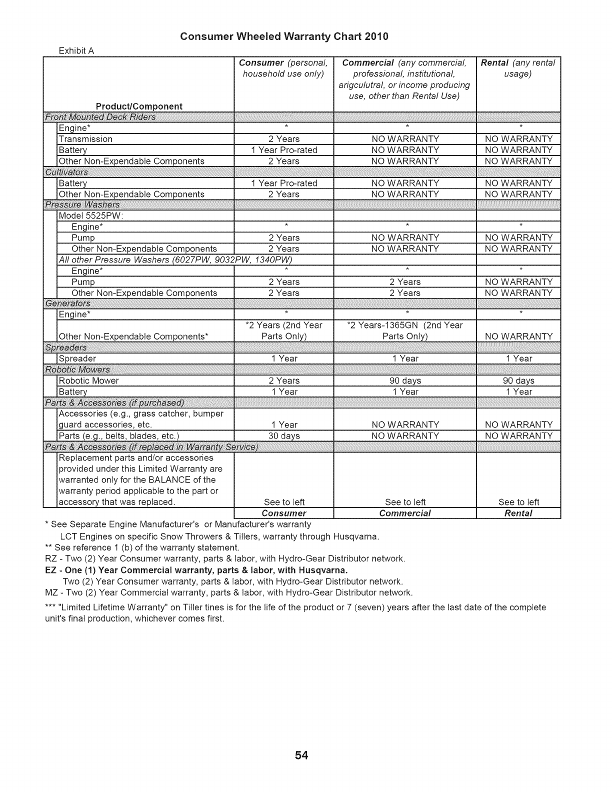
Exhibit A
Consumer Wheeled Warranty Chart 2010
Consumer (personal, Commercial (any commercial, Rental (any rental
household use only) professional, institutional usage)
arigculutral, or income producing
use, other than Rental Use)
Product/Component
Engine ....
Transmission
Battery
Other Non-Expendable Components
Battery
Other Non-Expendable Components
_reWa_rs
Model 5525PW:
Engine* * *
Pump 2 Years NO WARRANTY
Other Non-Expendable Components 2 Years NO WARRANTY
All other Pressure Washers (6027PW, 9032PW, 1340PW)
Engine* * *
Pump 2 Years 2 Years
Other Non-Expendable Components 2 Years 2 Years
_ _rators ................................................................................................ ::
Engine* * *
•2 Years (2nd Year *2 Years-1365GN (2nd Year
Other Non-Expendable Components* Parts Only) Parts Only)
_:re _rs ....' ....
Spreader 1 Year 1 Year
:_ tic _w_rs .
Robotic Mower 2 Years 90 days 90 days
Battery 1 Year 1 Year 1 Year
Part ::_ _ _ rie_ (i rc_ _d) .....
Accessories (e.g., grass catcher, bumper
guard accessories, etc. 1 Year NO WARRANTY NO WARRANTY
Parts (e.g., belts, blades, etc.) 30 days NO WARRANTY NO WARRANTY
_ _ _ _ (i re_fa _in_ ty :_ ice)::
Replacement parts and/or accessories
provided under this Limited Warranty are
warranted only for the BALANCE of the
warranty period applicable to the part or
accessory that was replaced. See to left See to left See to left
Consumer Commercial Rental
•See Separate Engine Manufacturer's or Manufacturer's warranty
LCT Engines on specific Snow Throwers & Tillers, warranty through Husqvarna.
•* See reference 1 (b) of the warranty statement.
RZ - Two (2) Year Consumer warranty, parts & labor, with Hydro-Gear Distributor network.
EZ - One (1) Year Commercial warranty, parts & labor, with Husqvarna.
Two (2) Year Consumer warranty, parts & labor, with Hydro-Gear Distributor network.
MZ - Two (2) Year Commercial warranty, parts & labor, with Hydro-Gear Distributor network.
..... Limited Lifetime Warranty" on Tiller tines is for the life of the product or 7 (seven) years after the last date of the complete
unit's final production, whichever comes first.
2 Years NO WARRANTY NO WARRANTY
1 Year Pro-rated NO WARRANTY NO WARRANTY
2 Years NO WARRANTY NO WARRANTY
1 Year Pro-rated NO WARRANTY NO WARRANTY
2 Years NO WARRANTY NO WARRANTY
,:1
NO WARRANTY
NO WARRANTY
NO WARRANTY
NO WARRANTY
NO WARRANTY
1 Year
54

SERVICE OTES
55

06.03.10 JA Husqvarna_ Printed in the U.S.A.
