Husqvarna 136 141 136Le 141Le Users Manual Operator's Manual, 136/ 141, 2003 06, Chain Saw
136, 141, 136LE, 141LE HUSO2003_USen_O0301010_
136, 141, 136LE, 141LE to the manual ea8a2062-b2b1-4666-b359-7e5331aa3271
2015-01-24
: Husqvarna Husqvarna-136-141-136Le-141Le-Users-Manual-317031 husqvarna-136-141-136le-141le-users-manual-317031 husqvarna pdf
Open the PDF directly: View PDF ![]() .
.
Page Count: 18
Instruction Manual
Read and follow all Safety Rules and Operating
Instructions before using this product. Failure to
do so can result in serious injury.
530163874 6/18/03
136 / 141
136LE / 141LE

2
IDENTIFICATION (WHAT IS WHAT?)
1
4
5
6
7
89
10
11
12
13
1415
1617
18
19
20
21
22
2423
1. Cylinder Cover
2. Front Handle
3. Front Hand Guard
4. Starter Cover
5. Chain Oil Tank
6. Starter Handle
7. Carburetor Adjusting Screw
8. Choke Control
9. Rear Handle
10. ON/OFF Stop Switch
11. Fuel Tank
12. Muffler
13. Bar Tip Sprocket
14. Saw Chain
15. Saw Bar
16. Chain Catcher
17. Chain Brake Assembly
18. Rear Hand Guard
19. Throttle Control/Trigger
20. Throttle Lock
21. Bar/Chain Adjustment Tool
22. Chain Tensioning Screw
23. Instruction Manual
24. Guide Bar Cover
321
IDENTIFICATION OF SYMBOLS
WARNING! This chain saw can be dangerous! Careless or improper
use can cause serious or even fatal injury.
Read and understand the instruction manual before using the chain saw.
Measuredmaximumkickback value without chain brake for the bar and
chain combination on the label.
XX_
There may be more symbols found on your unit other than those listed above. These
symbols may represent compliances, standards, or other matters concerning the product.
Sound pressure level at 15 meters (50 feet)
3
SAFETY RULES
WARNING: Always disconnect
spark plug wire and place wire where it can-
not contact spark plug to prevent accidental
starting when setting up, transporting, ad-
justing or making repairs except carburetor
adjustments.
Because a chain saw is a high-speed wood-
cutting tool, special safety precautions must
be observed to reduce the risk of accidents.
Careless or improper use of this tool can
cause serious injury.
PLAN AHEAD
SRead this manual carefully until you com-
pletely understand and can follow all safe-
ty rules, precautions, and operating in-
structions before attempting to use the
unit.
SRestrict the use of your saw to adult users
who understand and can follow safety
rules, precautions, and operating instruc-
tions found in this manual.
Snug
Fitting
Clothing
Safety
Shoes Safety Chaps
Heavy Duty
Gloves
Eye
Protection
Hearing
Protection
Safety Hat
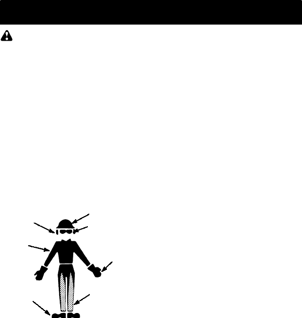
SWear protective gear. Always use steel-
toed safety footwear with non-slip soles;
snug-fitting clothing; heavy-duty, non-slip
gloves; eye protection such as non-fog-
ging, vented goggles or face screen; an
approved safety hard hat;and sound barri-
ers (ear plugs or mufflers) to protect your
hearing. Regular users should have hear-
ing checked regularly as chain saw noise
can damage hearing. Secure hair above
shoulder length.
SKeep all parts of your body away from the
chain when the engine is running.
SKeep children, bystanders, and animals a
minimum of 30 feet (10 meters) away from
the work area. Do not allow other people
or animals to be near the chain saw when
starting or operating the chain saw.
SDo not handle or operate a chain saw
whenyouarefatigued,ill, or upset,or if you
have taken alcohol, drugs, or medication.
You must be in good physical condition
and mentally alert. Chain saw work is
strenuous. If you have any condition that
might be aggravated by strenuous work,
check with your doctor before operating a
chain saw.
SCarefullyplanyour sawingoperation in ad-
vance. Donot start cutting until you have a
clear work area, secure footing, and, if you
are felling trees, a planned retreat path.
OPERATE YOUR SAW SAFELY
SDo not operate a chain saw with one hand.
Serious injury to the operator, helpers, by-
standers or any combination of these per-
sons may result from one-handed opera-
tion. A chain saw is intended for
two-handed use.
SOperatethe chain saw only in a well-venti-
lated outdoor area.
SDo not operate saw from a ladder or in a
tree.
SMake sure the chain will not make contact
with any object while starting the engine.
Never try to start the saw when the guide
bar is in a cut.
SDo not put pressure on the saw at the end
of the cut. Applying pressure can cause
you to lose control when the cut is com-
pleted.
SStop the engine before setting the saw
down.
SDo not operate a chain saw that is dam-
aged, improperly adjusted, or not com-
pletely and securely assembled. Always
replace bar, chain, hand guard, or chain
brake immediately if it becomes damaged,
broken or is otherwise removed.
SWith the engine stopped, hand carry the
chain saw with the muffler away from your
body, and the guide bar and chain to the
rear, preferably covered with a scabbard.
MAINTAIN YOUR SAW IN GOOD
WORKING ORDER
SHave all chain saw service performed by a
qualified service dealer with the exception
of the items listed in the maintenance sec-
tion ofthis manual. For example, if improp-
er tools are used to remove or hold the fly-
wheel when servicing the clutch, structural
damage to the flywheel can occur and
cause the flywheel to burst.
SMake certain the saw chain stops moving
when the throttle trigger is released. For
correction, refer to CARBURETOR AD-
JUSTMENTS.
SNever modify your saw in any way.
SKeepthe handles dry, clean, and free of oil
or fuel mixture.
SKeep fuel and oil caps, screws, and fas-
teners securely tightened.
SUse only Husqvarna accessories and re-
placement parts as recommended.
HANDLE FUEL WITH CAUTION
SDo not smoke while handling fuel or while
operating the saw.
SEliminate all sources of sparks or flame in
the areas where fuel is mixed or poured.
There should be no smoking, open flames,
or work that could cause sparks. Allow en-
gine to cool before refueling.
SMix and pour fuel in an outdoor area on
bare ground; store fuel in a cool, dry, well
4
ventilated place; and use an approved,
marked container for all fuel purposes.
Wipe up all fuel spills before starting saw.
SMove at least 10 feet (3 meters) from fuel-
ing site before starting engine.
STurn the engine off and let saw cool in a
non-combustible area, not on dry leaves,
straw, paper, etc. Slowly remove fuel cap
and refuel unit.
SStore theunit and fuel in an area where fuel
vapors cannot reach sparks or open
flames from waterheaters, electric motors
or switches, furnaces, etc.
KICKBACK
WARNING: Avoid kickback which
can result in serious injury. Kickback is the
backward,upward orsudden forwardmotion
of the guide bar occurring when the saw
chain near the upper tip of the guide barcon-
tacts any object such as a log or branch, or
when the wood closes in and pinches the
saw chain in thecut. Contactinga foreign ob-
ject in the wood can also result in loss of
chain saw control.
SRotationalKickbackcan occur when the
moving chain contacts an object at theup-
per tip of the guide bar. This contact can
cause the chain to dig into the object,
which stops the chain for an instant. The
result is a lightning fast, reverse reaction
which kicks the guide bar up and back to-
ward the operator.
SPinch-Kickback can occur when the the
wood closes in and pinches the moving
saw chain in the cut along the top of the
guide bar and the saw chain is suddenly
stopped. This sudden stopping of the
chain results in a reversal of the chain
force used to cut wood and causes the
saw to move in the opposite direction of the
chain rotation. The saw is driven straight
back toward the operator.
SPull-In can occur when the moving chain
contacts a foreign object in the wood in the
cut along the bottom of the guide bar and
the saw chain is suddenly stopped. This
sudden stoppingpulls thesaw forwardand
away from the operator and could easily
cause the operator to lose control of the
saw.
Avoid Pinch--Kickback:
SBe extremely aware of situations or ob-
structions that can cause material to pinch
the top of or otherwise stop the chain.
SDo not cut more than one log at a time.
SDo not twist the saw as the bar is with-
drawn from an undercut when bucking.
Avoid Pull--In:
SAlways begin cutting with the engine at full
speed and the saw housing against wood.
SUse wedges made of plastic or wood.
Never use metal to hold the cut open.
Kickback Path
Avoid Obstructions
Clear The Working Area
REDUCE THE CHANCE OF
KICKBACK
SRecognize that kickback can happen.
With a basic understanding of kickback,
you can reduce the element of surprise
which contributes to accidents.
SNever let the moving chain contact anyob-
ject at the tip of the guide bar.
SKeep the working area free from obstruc-
tions such as othertrees, branches,rocks,
fences, stumps, etc. Eliminate or avoid
any obstruction that your saw chain could
hit while you are cutting. When cutting a
branch, do not let the guide bar contact
branch or other objects around it.
SKeep your saw chain sharp and properly
tensioned. A loose or dull chain can in-
crease the chance of kickback occurring.
Follow manufacturer’s chain sharpening
andmaintenanceinstructions. Check ten-
sion at regular intervals with the engine
stopped, never with the engine running.
Make sure thebar clampnuts aresecurely
tightened after tensioning the chain.
SBegin and continue cutting at full speed. If
the chain is moving at a slower speed,
there is greater chance of kickback occur-
ring.
SCut one log at a time.
SUse extreme caution when re-entering a
previous cut.
SDo not attempt cuts starting with the tip of
the bar (plunge cuts).
SWatch for shifting logs or other forces that
could close a cut and pinch or fall into
chain.
SUse the Reduced--Kickback Guide Bar
and Low--Kickback Chain specified for
your saw.
MAINTAIN CONTROL
Never reverse
hand positions
Stand to the left of
the saw
5
Thumb on underside of
handlebar
Elbow locked
SKeep a good, firm grip on thesaw with both
hands when the engine is running and
don’t let go. A firm grip will help youreduce
kickback and maintain control of the saw.
Keep the fingers of your left hand encir-
cling and your left thumb under the front
handlebar. Keep your right hand com-
pletely around the rear handle whether
your are right handed or left handed. Keep
your left arm straight with the elbow
locked.
SPosition your left hand on the front handle-
bar so it is in a straight line with your right
hand on the rear handle when making
bucking cuts. Never reverse right and left
hand positions for any type of cutting.
SStandwithyour weightevenly balancedon
both feet.
SStand slightly to the left side of the saw to
keep your body from being in a direct line
with the cutting chain.
SDo not overreach. You could be drawn or
thrown off balance and lose control of the
saw.
SDo not cut above shoulder height. It is diffi-
cult to maintain control of saw above
shoulder height.
KICKBACK SAFETY FEATURES
WARNING: The following features
are included on your saw to help reduce the
hazard of kickback; however, such features
will not totally eliminate this dangerousreac-
tion. As achain saw user, do notrely only on
safety devices. You must follow all safety
precautions, instructions, and maintenance
in this manual to help avoid kickback and
other forces which can result in serious
injury.
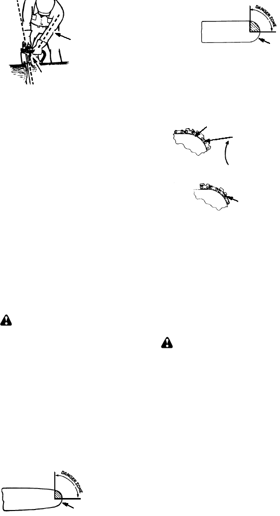
SReduced--Kickback Guide Bar, designed
with a small radius tip which reduces the
size of the kickback danger zone on the
bar tip. A Reduced--Kickback Guide Bar
has been demonstratedto significantly re-
duce the number and seriousness of kick-
backs when tested in accordance with
safety requirements for gasoline powered
chain saws as set by ANSI B175.1.
Small Radius Tip
Reduced Kickback Symmetrical Guide Bar
Symmetrical Guide Bar
Large Radius Tip
SLow--Kickback Chain, designed with a
contoured depth gauge and guard link
which deflect kickback force and allow
wood to gradually ride into the cutter.
Low--Kickback Chain has met kickback
performance requirements when tested
on a representative sample of chain saws
below 3.8 cubic inch displacement speci-
fied in ANSI B175.1.
Low---Kickback
Chain
Not a Low---Kickback Chain
Can Obstruct Material
Contoured Depth Gauge
Elongated Guard Link
Deflects
kickback force
and allows wood
to gradually ride
into cutter
SFront Hand Guard, designed to reduce the
chance of your left hand contacting the
chain if your hand slips offthe fronthandle-
bar.
SPosition of front and rear handlebars, de-
signed with distance betweenhandles and
“in-line” with each other. The spread and
“in-line” position of the hands provided by
this design work together to give balance
and resistance in controlling the pivot of
the saw back toward the operator if kick-
back occurs.
CHAIN BRAKE AND CKA ANGLE
SChain Brake, designed to stop the chain in
the event of kickback.
WARNING: WE DO NOT REP-
RESENT AND YOU SHOULD NOT AS-
SUME THAT THE CHAIN BRAKE WILL
PROTECT YOU IN THE EVENT OF A
KICKBACK. Kickback is a lightning fast ac-
tion which throws the bar and rotating chain
back and up toward the operator. Kickback
can be caused by allowing contact of the bar
tip in the danger zone with any hard object.
Kickback can also be caused by pinching the
saw chain along the topof the guide bar. This
action may push the guide bar rapidly back
toward the operator. Either of these events
may cause you to lose control of the saw
which could result in serious injury or even
death. DO NOT RELY UPON ANY OF THE
DEVICES BUILT INTO YOUR SAW. YOU
SHOULD USE THE SAW PROPERLY AND
CAREFULLY TO AVOID KICKBACK. Re-
duced--kickback guide bars and low--kick-
back saw chains reduce the chance and
magnitude of kickback and are recom-
mended. Your saw has alow kickback chain
and bar as original equipment. Repairs on a

6
chain brake should be made by an autho-
rized servicing dealer. Take your unit to the
place of purchase if purchased from a
Husqvarna servicing dealer, or to the near-
est authorized Husqvarna service dealer.
STip contact in some cases may cause a
lightning fast reverse REACTION, kicking
the guide bar up and back toward the oper-
ator.
SPinching the saw chain along the top of the
guide bar may push the guide bar rapidly
back toward the operator.
SEither of these reactions may cause you to
lose control of the saw which could result
in serious injury. Do not rely exclusively
upon thesafety devices built into your saw.
WARNING: Computed kickback
angle (CKA) listed on your saw and listed in
the CKA table below represents angle of
kickback your bar and chain combinations
will have when tested in accordance with
CSA (Canadian Standards Association) and
ANSI standards. When purchasing replace-
ment bar and chain, considerations should
be given to the lower CKA values. Lower
CKA values represent safer angles to the
user, higher values indicate more angle and
higher kick energies. Computed angles rep-
resented in the non-activated column indi-
cate total energy and angle associated with-
out activation of the chain brake during
kickback. Activated angle represents chain
stopping time relative to activation angle of
chain break and resulting kick angle of saw.
In all cases lower CKA values represent a
safer operating environment for the user.
The following guide bar and chain combina-
tions meet kickback requirements of CSA
Standards Z62.1, Z62.3, & ANSI B175.1
when used on saws listed in this manual.
Use of bar and chain combinations other
than those listed is not recommended and
may not meet the CKA requirements per
standard.
Computed kickback angle (CKA) Table
BAR
Type Length CHAIN TYPE
0.050 GA 14!91VG/VJ--- 52
MODEL
0.050 GA
16!91VG---56
25_
136 25_
141
141 0.050 GA 18!H 3 0 --- 7 2 38_
CKA WITHOUT
CHAIN BRAKE
136
0.050 GA
16!91VG---56
25_
NOTE: If this saw is to be used for
commercial logging, a chain brake is
required and shall not be removed or
otherwise disabled to comply with Federal
OSHA Regulations for Commercial Logging.
Contact your authorized Husqvarna service
dealer.
SAFETY NOTICE: Exposure to
vibrations through prolongeduse of gasoline
powered hand tools could cause blood
vessel or nerve damage in the fingers,
hands, and joints of people prone to
circulation disorders or abnormal swellings.
Prolonged use in cold weather has been
linked to blood vessel damage in otherwise
healthy people. If symptoms occur such as
numbness, pain, loss of strength, change in
skin color or texture, or loss of feeling in the
fingers, hands, or joints, discontinue the use
of this tool and seek medical attention. An
anti-vibrationsystem does not guaranteethe
avoidance of these problems. Users who
operate power tools on a continual and
regular basis must monitor closely their
physical condition and the condition of this
tool.
SPECIALNOTICE:Your saw is equipped
with a temperaturelimiting muffler and spark
arresting screen which meets the
requirements of California Codes 4442 and
4443. All U.S. forest land and the states of
California, Idaho, Maine, Minnesota, New
Jersey, Oregon, and Washington require
many internal combustion engines to be
equipped with a spark arrestor screen by
law. If you operate a chain saw in a state or
locale where such regulations exist, you are
legally responsible for maintaining the
operating condition of these parts. Failure to
do so is a violation of the law. Refer to the
SERVICE AND ADJUSTMENTS section for
maintenance of the Spark Arresting Screen.
Failure to follow all Safety Rules and
Precautions can result in serious injury. If
situations occur which are not covered in this
manual, use careandgoodjudgement. If you
need assistance, contact your authorized
service dealer.
STANDARDS
CSA Z62.1 “Chain Saws -- Occupational
Health and Safety”
CSA Z62.3 “Chain Saw Kickback Occupa-
tional Health and Safety”
ANSI B175.1--2000 -- “American National
Standard for Powered Tools -- Gasoline
Powered Chain Saw -- Safety Require-
ments”
7
ASSEMBLY
Protective gloves (not provided) should be
worn during assembly.
ATTACHING THE BAR & CHAIN (If
not already attached)
WARNING: Recheck each assem-
bly step if the saw is received assembled. Al-
ways wear gloves when handling the chain.
The chain is sharp and can cut you even
when it is not moving!
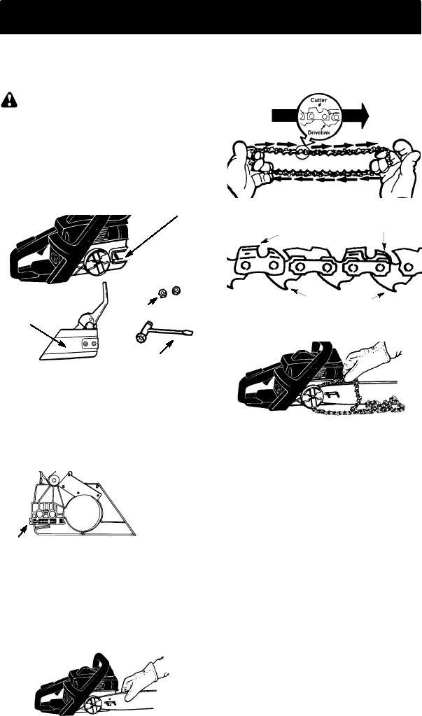
1. Loosen and remove the clamp nuts and
the bar clamp from the saw.
2. Remove the plastic shipping spacer (if
present).
Bar Clamp/
Chain Brake Bar Clamp Nuts
Bar Tool
Location of shipping spacer
3. An adjusting pin and screw is used to ad-
just the tension of the chain. It is very im-
portant when assembling the bar, that
the pin located on the adjusting screw
aligns into a hole in the bar. Turning the
screw will move the adjustment pin up
and down the screw. Locate this adjust-
ment before you begin mounting the bar
onto the saw. See illustration.
Adjustment located on Bar Clamp
Inside view of
Chain Brake
4. Turn the adjusting screw counterclock-
wise to move the adjusting pin almost as
far as it will go to the rear. This should al-
low the pin to be near the correct posi-
tion. Further adjustment may be neces-
sary as you mount the bar.
5. Slide guide bar behind clutch drum until
guide bar stops against clutch drum
sprocket.
Mount the Bar
6. Prepare the chain by checking the proper
direction. Without following the illustration it
is easy to place the chain on the saw in the
wrong direction. Use the illustration of the
chain to determine the proper direction.
CUTTERS MUST FACE IN
DIIRECTION OF ROTATION
Tip of
Bar
Cutters Depth Gauge
Drive Links
7. Place chain over and behind clutch, fit-
ting the drive links in the clutch drum
sprocket.
Place chain onto the s
p
rocket
8. Fit bottom of drive links between the
teeth in the sprocket in the nose of the
guide bar.
9. Fit chain drive links into bar groove.
10. Pull guide bar forward until chain is snug
in guide bar groove. Ensure all drive
links are in the bar groove.
11 Now, install chain brake making sure the
adjusting pin is positioned in the lower
hole in the guide bar. Remember this pin
moves the bar forward and backward as
the screw is turned.
12. Install chain brake nuts and fingertighten
only. Once the chain is tensioned, you
will need to tighten chain brake nuts.
CHAIN TENSION (Including units with
chain already installed)
NOTE:When adjusting chain tension,
make sure the bar nuts are finger tight only.
Attempting to tension the chain when the bar
nuts are tight can cause damage.
Checking the tension:
Use the screwdriver end of the combination
screwdriver/wrench tool to move the chain
around the bar. If thechain does not rotate,it
is too tight. If too loose, the chain will sag be-
low the bar.
8
Chain Brake Nuts Chain Adjustment
Tool (Bar Tool)
Guide
Bar
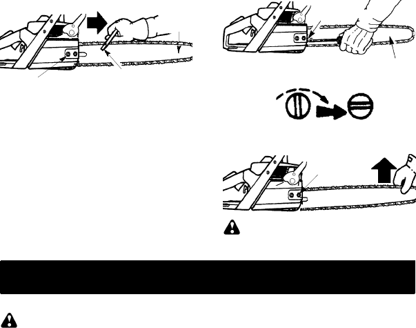
Adjusting the tension:
Chain tension is very important. Chain
stretches during use. This is especially true
during the first few times you use your saw.
Always check chain tension each time you
use and refuel your saw.
You can adjust the chain tension by loosening
the bar clamp nuts and turning the adjusting
screw 1/4 of a turn while lifting up on the bar.
SIf chain is too tight, turn adjusting
screw 1/4 turn counterclockwise.
SIf chain is too loose, turn adjusting
screw 1/4 turn clockwise.
Adjusting
Screw
Chain Brake Nuts Guide Bar
Adjusting Screw -- 1/4 Turn
SLift up the tip of the bar and tighten the
chain brake nuts with the bar tool.
SRecheck chain tension.
Chain Brake
Nuts
WARNING: If the saw is operated
with a loose chain, the chain could jump off
the guide bar and result in serious injury.
FUELING & LUBRICATION
FUELING ENGINE
WARNING: Remove fuel cap slowly
when refueling.
This engine is certified to operate on
unleaded gasoline. Before operation,
gasoline must be mixed with a good quality
synthetic 2-cycle air-cooled engine oil
designed to be mixed at a ratio of 40:1. A
40:1 ratiois obtainedby mixing 3.2 ouncesof
oil with 1 gallon of unleaded gasoline. DO
NOT USE automotive oil or boat oil. These
oils will cause engine damage. When mixing
fuel, follow instructions printed on container.
Once oil is added to gasoline, shake
container momentarily to assure that the fuel
is thoroughly mixed. Always read and follow
the safety rules relating to fuel before fueling
your unit.
BAR AND CHAIN LUBRICATION
The bar and chain require continuous lubri-
cation. Lubrication is provided by the auto-
matic oiler system when the oil tank is kept
filled. Lack of oil will quickly ruin the bar and
chain. Too little oil will cause overheating
shown by smoke coming from the chain and/
or discoloration of the bar.
In freezing weatheroil will thicken, making it
necessary to thin bar and chain oil with a
small amount (5 to 10%) of #1 Diesel Fuel or
kerosene. Bar and chain oil must be free
flowing for the oil system to pump enough oil
for adequate lubrication.
Genuine Husqvarna bar and chain oil is rec-
ommended to protect your unit against exces-
sive wear from heat and friction. Husqvarna oil
resists high temperature thinning.
If Husqvarna bar oil is not available, use a good
grade SAE 30 oil.
SNever use waste oil for bar and chain lu-
brication.
SAlways stop the engine before removing
the oil cap.
IMPORTANT
Experience indicates that alcohol--blended
fuels (called gasohol or using ethanol or
methanol) can attract moisture which leads
to separation and formation of acids during
storage. Acidic gas can damage the fuel
system of an engine while in storage. To
avoid engine problems, the fuel system
should be emptied before storage for 30
days or longer. Drain the gas tank, start the
engine and let it run until the fuel lines and
carburetor are empty. Use fresh fuel next
season. See STORAGE section for addi-
tional information.
9
OPERATING YOUR UNIT
WARNING: The chain must not move
when the engine runs at idle speed. If the chain
moves at idle speed refer to CARBURETOR
ADJUSTMENT within this manual. Avoid con-
tact with the muffler. A hot muffler can cause
serious burns.
To stop the engine move the switch to the
STOP position.
To start the engine hold the saw firmly on
the ground as illustrated below. Make sure
the chain is free to turn without contacting
any object.
Hold saw firmly while pulling starter rope.
Use only 15”--18” of rope per pull.
Important points to remember
When pulling the starter rope, do not use the full
extent of the rope as this can cause the rope to
break. Do not let starter rope snap back. Hold
the handle and let the rope rewind slowly.
For cold weather starting, start the unit at full
choke; allow the engine to warm up before
squeezing the throttle trigger.
NOTE: Do not cut material with the choke/
fast idle lever at the FULL CHOKE position.
STARTING A COLD ENGINE (or a
warm engine after running out of
fuel)
NOTE:In the following steps, when the cho-
ke/fast idle lever is pulled out to the full extent,
the correct throttle setting for starting is set au-
tomatically.
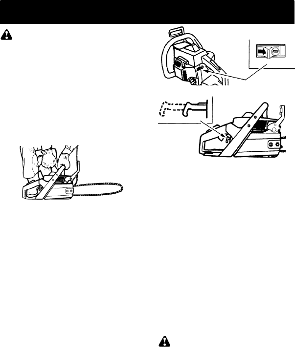
1. Move ON/STOP switch to the ON position.
2. Pull the choke/fast idle lever out to thefull
extent.
3. Pull starter rope quickly with your right
hand a maximum of 10 times. Then, pro-
ceed to the next step.
NOTE: If the engine sounds as if it is trying
to start before the 10th pull, stop pulling and
immediately proceed to the next step.
4. Push the choke/fast idle lever in com-
pletely (to the OFF CHOKE position).
5. Pull the starter rope quickly with your
right hand until the engine starts.
6. Allow the engine to run for approximately
5 seconds. Then, squeeze and release
throttle trigger to allow engine to return to
idle speed.
ON/STOP SWITCH
CHOKE/FAST IDLE LEVER
FULL OFF
STARTING A WARM ENGINE
1. Move ON/STOP switch to the ON position.
2. Pull the choke/fast idle lever out to the full
extent; then, push the choke/fast idle
lever in completely (to the OFF CHOKE
position).
3. Pull the starter rope quickly with your
right hand until the engine starts.
4. Squeeze and release throttle trigger to
allow engine to return to idle speed.
DIFFICULT STARTING (or starting a
flooded engine)
The engine may be flooded with too much
fuel if it has not started after 10 pulls.
Flooded engines can be cleared of excess
fuel by following the warm engine starting
procedure listed above. Insure the ON/
STOP switch is in the ON position.
Starting could require pulling the starterrope
handle many times dependingon how badly
the unit is flooded. If engine fails to start refer
to the TROUBLESHOOTING TABLE.
CHAIN BRAKE
WARNING: If the brake band is worn
too thin it may break when the chain brake is
triggered. With a broken brake band, the chain
brake will not stop the chain. The chain brake
should be replaced by an authorized service
dealer if any part is worn to less than 0.020!
(0.5 mm) thick. Repairs on a chain brake
should be made by an authorized service deal-
er. Take your unit to the place of purchase if
purchased from a servicing dealer, or to the
nearest authorized Husqvarna Service Dealer.
SThis saw is equipped with a chain brake.
The brake is designed to stop the chain if
kickback occurs.
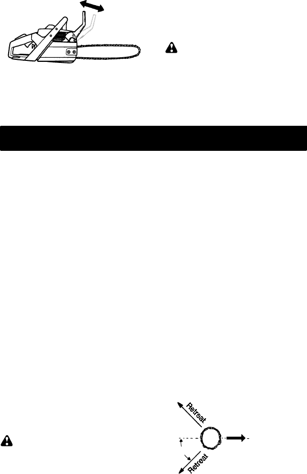
SThe inertia--activated chain brake is
activated if the front hand guard is pushed
forward, either manually (by hand) or
automatically (by sudden movement).
SIf the brake is already activated, it is
disengagedby pulling thefronthandguard
back toward the front handle as far as
possible.
10
SWhen cutting with the saw, the chain brake
must be disengaged.
Disengaged
Engaged
Braking function control
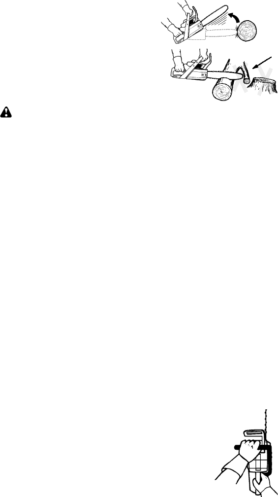
CAUTION: The chain brake must be
checked several times daily. The engine
must be running whenperforming this proce-
dure. This is the only instance when the saw
should be placed on the ground with the en-
gine running.
Place the saw on firm ground. Hold the han-
dles with both hands and apply full throttle.
Activate the chain brake by turning your left
wrist against the hand guard without releas-
ing your grip around the front handle. The
chain should stop immediately.
Inertia activating function control
WARNING: When performing the fol-
lowing procedure, the engine must be turned
off.
The chain brake must be checked several
times daily. Hold the chain saw approximate-
ly 14!(35 cm) above a stump or other firm
object. Release your grip on the front handle
and let the saw, by its own weight, rotate
around the rear handle. When the tip of the
bar hits the stump, thebrake shouldactivate.
CUTTING METHODS
IMPORTANT POINTS
SCheck chain tension before first use and
after 1 minute of operation. See CHAIN
TENSION in the ASSEMBLY section.
SCut wood only. Do not cut metal, plastics,
masonry, non-wood building materials, etc.
SStop the saw if the chain strikes a foreignob-
ject. Inspect the saw and repair parts as
necessary.
SKeepthechain outof dirt andsand. Even a
small amount of dirt will quickly dull achain
and increase the possibility of kickback.
SPractice cutting a few small logs using the
following techniques to get the “feel” of us-
ing your saw before you begin a major
sawing operation.
SSqueeze the throttle trigger and allow
the engine to reach full speed before
cutting.
SBegin cutting with the saw frame
against the log.
SKeep the engine at full speed the en-
tire time you are cutting.
SAllow the chain to cut for you. Exert
only light downward pressure.
SRelease the throttle trigger as soon as
the cut is completed, allowing the en-
gine to idle. If you run the saw at full
throttle without a cutting load, unnec-
essary wear can occur.
STo avoid losing control when cut is
complete, do not put pressure on saw
at end of cut.
SStop the engine before setting the saw
down after cutting.
TREE FELLING TECHNIQUES
WARNING: Check for broken or
dead branches which can fall while cutting
causing serious injury. Do notcut near build-
ings or electrical wires if you do not know the
direction of treefall, norcut atnight since you
will not be ale to see well, nor during bad
weather such as rain, snow, or strong winds,
etc. If the tree makes contact with any utility
line, the utility company should be notified
immediately.
SCarefully plan your sawing operation in ad-
vance.
SClear the work area. You need a clear area
all around the tree so you can have secure
footing.
SThe chain saw operator should keep on the
uphill side of the terrain as the tree is likely to
roll or slide downhill after it is felled.
SStudy the natural conditions that can cause
the tree to fall in a particular direction.
Natural conditions that can cause a tree to fall
in a particular direction include:
SThe wind direction and speed.
SThe lean of the tree. The lean of a tree might
not be apparent due to uneven or sloping ter-
rain. Use a plumb or level to determine the
direction of tree lean.
SWeight and branches on one side.
SSurrounding trees and obstacles.
Look for decay and rot. If the trunk is rotted, it
can snap and fall toward the operator. Check
for broken or dead branches which can fall on
you while cutting.
Make sure there is enough room for the tree to
fall. Maintain a distance of 2-1/2 tree lengths
from the nearest person or other objects. En-
gine noise can drown out a warning call.
Remove dirt, stones, loose bark, nails, staples,
and wire from the tree where cuts are to be
made.
Plan a clear retreat path to the rear and diago-
nal to the line of fall.
Direction of Fall
45_
Plan a clear retreat path
FELLING LARGE TREES
(15 cm in diameter or larger)
The notch method is used to fell large trees.
A notch is cut on the side of the tree in the de-
sired direction of fall. After a felling cut is
11
made on the opposite side of tree, the tree
will tend to fall into the notch.
NOTE: If the tree has large buttress roots,
remove them beforemaking the notch. If us-
ing saw to remove buttress roots, keep saw
chain from contacting ground to preventdull-
ing of the chain.
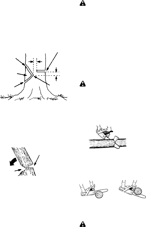
NOTCH CUT AND FELLING THE
TREE
SMake notch cut by cutting the top of the
notch first. Cut through 1/3 of the diameter
of thetree. Next complete thenotch by cut-
ting the bottom of the notch. See illustra-
tion. Once the notch is cut remove the
notch of wood from the tree.
Notch
First cut
Second cut
Final (felling) cut here.
2!(5 cm) above center of notch.
5cm
5cm
Hinge
SAfter removing the cutout of wood, make
the felling cut on the opposite side of the
notch. This is done by making a cut about
two inches higher than the center of the
notch. This will leave enough uncut wood
between the felling cut and the notch to
form a hinge. This hinge will help prevent
the tree from falling in the wrongdirection.
Opening
of felling
cut
Closing
of
notch
Hinge holds tree on stump and helps
control fall
NOTE:Before felling cut is complete, use
wedges to open the cut when necessary to
control thedirection offall. To avoidkickback
and chain damage, use wood or plastic
wedges, but never steel or iron wedges.
SBe alert to signs that the tree is ready to fall:
cracking sounds, widening of the felling cut,
or movement in the upper branches.
SAs tree starts to fall, stop saw, put it down,
and get away quickly on your planned re-
treat path.
SDO NOT cut down a partially fallen tree with
your saw. Be extremely cautious with par-
tially fallen trees that may be poorly sup-
ported. When a tree doesn’t fall completely,
set the saw aside and pull down the tree with
a cable winch, block and tackle, or tractor.
CUTTING A FALLEN TREE
(BUCKING)
Bucking is the term used for cutting a fallen
tree to the desired log length.
WARNING: Do not stand on the log
being cut. Any portion can roll causing loss
of footing and control. Do not stand downhill
of the log being cut.
IMPORTANT POINTS
SCut only one log at a time.
SCut shattered wood very carefully; sharp
pieces of wood could be flung toward oper-
ator.
SUse a sawhorse to cut small logs. Never
allow another person to hold the log while
cutting and never hold the log with your leg
or foot.
SDo not cut in an area where logs, limbs,
and roots are tangled. Drag the logs into a
clear area before cutting by pulling out ex-
posed and cleared logs first.
TYPES OF CUTTING USED FOR
BUCKING
WARNING:If saw becomes pinched
or hung in a log, don’t try to force it out. You
can lose control of the saw resulting in injury
and/or damage to the saw. Stop the saw,
drive a wedge of plastic or wood into the cut
until the saw can be removed easily. Restart
the saw and carefully reenterthe cut. Do not
attemptto restartyoursaw whenit is pinched
or hung in a log.
Turn saw OFF and use a plastic or
wooden wedge to force cut open.
Use a wedge to remove pinched saw
Overcuttingbegins on the top side of the log
with the saw against the log. When overcut-
ting use light downward pressure.
Overcutting Undercutting
Undercuttinginvolves cutting on the under-
side of the log with top of saw against the log.
When undercutting use light upward pres-
sure. Hold saw firmly and maintain control.
The saw will tend to push back toward you.
WARNING: Never turn saw upside
down to undercut. The saw cannot be con-
trolled in this position.
Always make your first cut on the compres-
sion side of the log. The compression side of
the log is where the pressure of the log’s
weight is concentrated.
12
Second cut
First cut on compression side of log
First cut on compression side of log
Second cut
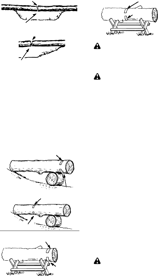
BUCKING WITHOUT A SUPPORT
SOvercut through 1/3 of the diameter of the
log.
SRoll the log over and finish with a second
overcut.
SWatch for logs with a compression side to
prevent the saw from pinching. See illustra-
tion for cutting logs with a compression side.
BUCKING USING A LOG OR SUP-
PORT STAND
SRemember your first cut is always on the
compression side of the log. (Refer to the il-
lustration below for your first and second
cuts).
SYour first cut should extend 1/3 of the
diameter of the log.
SFinish with your second cut.
1st Cut
2nd Cut
Using a log for support
2nd Cut
1st Cut
1st Cut
2nd Cut
Using a support stand
1st Cut
2nd Cut
LIMBING AND PRUNING
WARNING: Be alert for and guard
against kickback. Do not allow the moving
chain to contact any other branches or ob-
jects at the nose of the guide bar when limb-
ing or pruning. Allowing suchcontact can re-
sult in serious injury.
WARNING:Never climb intoa treeto
limb or prune. Do not stand on ladders, plat-
forms, a log, or in any position which can
cause you to lose your balance or control of
the saw.
IMPORTANT POINTS
SWork slowly, keeping both hands firmly
gripped on the saw. Maintain secure foot-
ing and balance.
SWatch out for springpoles. Use extreme
caution when cutting small size limbs.
Slender material may catch the saw chain
and be whipped toward you or pull you off
balance.
SBe alert for springback. Watch out for
branches that are bent or under pressure.
Avoid being struck by the branch or the
saw when the tension in the wood fibers is
released.
SKeep a clear work area. Frequently clear
branches out of the way to avoid tripping
over them.
LIMBING
SAlways limb a tree after it is cut down. Only
then can limbing be done safely and prop-
erly.
SLeave the larger limbs underneath the
felled tree to support the tree as you work.
SStart at base of the felled tree and work to-
ward the top, cutting branches and limbs.
Remove small limbs with one cut.
SKeep the tree between you and the chain.
Cut from the side of the tree opposite the
branch you are cutting.
SRemove larger, supporting branches with
the cutting techniquesdescribed in BUCK-
ING WITHOUT A SUPPORT.
SAlways use an overcut to cut small and
freely hanging limbs. Undercutting could
cause limbs to fall and pinch saw.
PRUNING
WARNING: Limit pruning to limbs
shoulder height or below. Do not cut if
branches are higher than your shoulder. Get
a professional to do the job.
13
SMake your first cut 1/3 of the way through
the bottom of the limb.
SNext make a 2nd cut all the way through
the limb. Then cut a third overcut leaving
a 1 to2 inch collar from thetrunk of the tree.
First cut
Second cut
Third cut
Collar
Pruning technique
SERVICE AND ADJUSTMENTS
WARNING: Muffler is very hotduring
and after use. Do not touch the muffler or al-
low combustible material such as dry grass
or fuel to do so.
We recommend all service and adjustments
not listed in this manual be performed by an
Authorized Service Dealer.
MAINTENANCE SCHEDULE
Check:
Fuel mixture level Before each use....
Bar lubrication Before each use.......
Chain tension Before each use.......
Chain sharpness Before each use....
For damaged parts Before each use..
For loose caps Before each use......
For loose fasteners Before each use...
For loose parts Before each use......
Inspect and Clean:
Bar Before each use................
Complete saw After each use.......
Air filter Every 5 hours*.............
Chain brake Every 5 hours*........
Spark arresting screen
and muffler Every 25 hours*.........
Replace spark plug Year ly.
Replace fuel filter Year ly...
* Hours of Operation
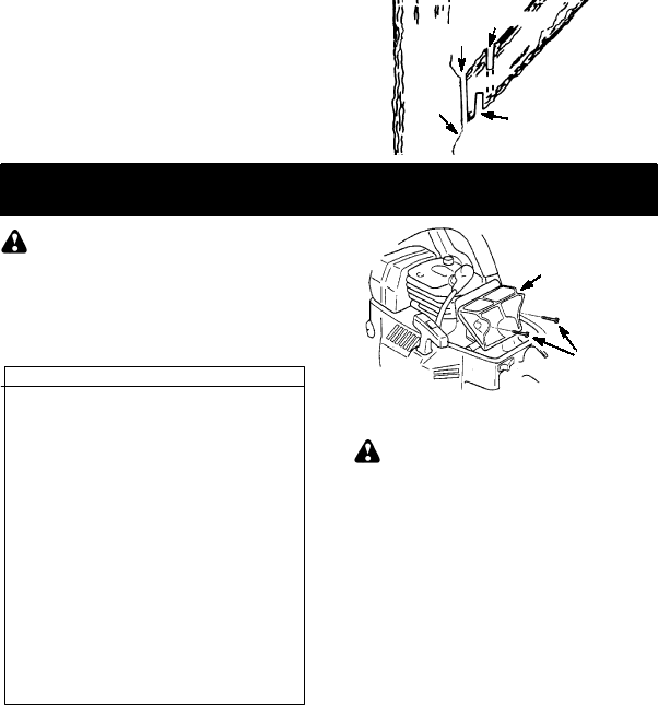
AIR FILTER
CAUTION:Do not clean filter in gasoline
or other flammable solvent to avoid creating
a fire hazard or producing harmful evapora-
tive emissions.
Cleaning the air filter:
A dirty air filter decreases engine perform-
ance and increases fuel consumption and
harmful emissions. Always clean after 15
tanks of fuel or 5 hours of operation, which-
ever comes first. Clean more frequently in
dusty conditions. A used air filter can never
be completely cleaned. It is advisable to re-
place your air filter witha newone afterevery
50hoursof operation,or annually,whichever
comes first.
1. Loosen 3 screws on cylinder cover.
2. Remove cylinder cover.
3. Remove air filter.
4. Clean the air filter using hot soapy water.
Rinse with clean cool water. Air dry com-
pletely before reinstalling.
5. Reinstall air filter.
6. Reinstall cylinder cover and 3 screws.
TIghten securely.
Air Filter
Air Filter
Screws
CARBURETOR ADJUSTMENTS
WARNING:Thechainwill bemoving
during most of this procedure. Wear your
protective equipment and observe all safety
precautions. The chain must not move at idle
speed.
The carburetor has been carefully set at the
factory. Adjustments may be necessary if
you notice any of the following conditions:
SChain moves at idle. See IDLE SPEED--T
adjusting procedure.
SSaw will not idle. See IDLE SPEED--T ad-
justing procedure.
Idle Speed---T
Allow engine to idle. If the chain moves, idle
is too fast. Ifthe engine stalls, idle is too slow.
Adjust speed until engine runs without chain
movement (idle too fast) or stalling (idle too
s l ow ) . T he i dl e s peed s c r ew is labeled "T".
S Tur n i dl e s peed s c r ew ( T ) c l oc k w i s e t o i n-
crease engine speed.
STurn idle speed screw (T) counterclock-
wise to decrease engine speed.
If you require further assistance or are unsure
about performing this procedure, contact your
authorized service dealer.
BAR MAINTENANCE
If your saw cuts to one side, has to be forced
through the cut, or been run with an improper
amount of bar lubrication it may be neces-
sary to service your bar. A wornbar will dam-
age your chain and make cutting difficult.
After each use, ensure ON/STOP switch is
in the STOP position, then clean all sawdust
from the guide bar and sprocket hole.
To maintain guide bar:
SMove ON/STOP switch to the STOP posi-
tion.
SLoosen and remove chain brake nuts and
chain brake. Remove bar and chain from
saw.
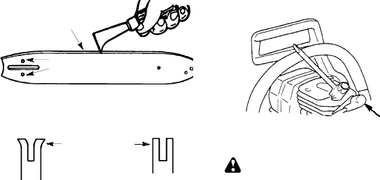
14
SClean the oil holes and bar groove after
each 5 hours of operation.
Remove Sawdust From
Guide Bar Groove
Oil Holes
SBurring of guide bar rails is a normal
process of rail wear. Remove these burrs
with a flat file.
SWhen rail top is uneven, use a flat file to re-
store square edges and sides.
Correct GrooveWorn Groove
File Rail Edges
and Sides
Square
Replace guide bar when the groove is worn,
the guide bar is bent or cracked, or when
excess heating or burring of the rails occurs.
If replacement is necessary, use only the
guide bar specified for your saw in the repair
parts list or on the decal located on thechain
saw.
CHAIN SHARPENING
Chain sharpening is a complicated task that
requires special tools. We recommended
you refer chain sharpening to a professional
chain sharpener.
IGNITION TIMING
Ignition timing is fixed and nonadjustable.
SPARK PLUG
The spark plug should be replaced each
year to ensure the engine starts easier and
runs better.
1. Loosen 3 screws on cylinder cover.
2. Remove the cylinder cover.
3. Pull off the spark plug boot.
4. Remove spark plug from cylinder and
discard.
5. Replace with Champion RCJ--7Y spark
plug and tighten securely with a 3/4 inch
(19 mm) socket wrench. Spark plug gap
should be 0.025 inches (0,6 mm).
6. Reinstall the spark plug boot.
7. Reinstall the cylinder cover and 3
screws. Tighten securely.
Spark Plug Boot
STORAGE
WARNING:Stop engine and allow to
cool, and secure the unit before storing or
transporting in a vehicle. Store unit and fuel
in an area where fuel vapors cannot reach
sparks or open flames from water heaters,
electric motors or switches, furnaces, etc.
Storeunit with all guards in place. Position so
that any sharp object cannot accidentally
cause injury to passersby. Store the unit out
of reach of children.
SBefore storing, drain all fuel from the unit.
Start engine and allow to run until it stops.
SClean the unit before storing. Pay particu-
lar attention to the air intake area, keeping
it free of debris. Use a mild detergent and
sponge to clean the plastic surfaces.
SDo notstore theunit or fuel in a closed area
where fuel vapors can reach sparks or an
openflame from hot water heaters,electric
motors or switches, furnaces, etc.
SStore in a dry area out of the reach of chil-
dren.
CAUTION:It is important to prevent gum
deposits from forming in essential fuel sys-
tem parts such as the carburetor, fuel filter,
fuel hose, or fuel tank during storage. Alco-
hol blended fuels (called gasohol or using
ethanol or methanol) can attract moisture
which leads to fuel mixture separation and
formationof acids during storage. Acidic gas
can damage the engine.

15
TROUBLE CAUSE REMEDY
Engine will not
start or will run
only a few
seconds after
starting.
1. Ignition switch off.
2. Engine flooded.
3. Fuel tank empty.
4. Spark plug not firing.
5. Fuel not reaching
carburetor.
1. Move ignition switch to ON.
2. See “Difficult Starting” in
Operation Section.
3. Fill tank with correct fuel mixture.
4. Install new spark plug.
5. Check for dirty fuel filter; replace.
Check for kinked or split fuel line;
repair or replace.
Engine will
not idle
properly.
1. Carburetor requires
adjustment.
2. Crankshaft seals worn.
1. See “Carburetor Adjustment” in the
Service and Adjustments Section.
2. Contact an authorized service dealer.
1. Air filter dirty.
2. Spark plug fouled.
3. Chain brake engaged.
4. Carburetor requires
adjustment.
Engine will not
accelerate,
lacks power,
or dies under
a load.
1. Clean or replace air filter.
2. Clean or replace plug and regap.
3. Disengage chain brake.
4. Contact an authorized service dealer.
Engine
smokes
excessively.
1. Too much oil mixed with
gasoline. 1. Empty fuel tank and refill with
correct fuel mixture.
WARNING: Always stop unit and disconnect spark plug before performing all of
the recommended remedies below except remedies that require operation of the unit.
TR
O
UBLE
S
H
O
O
TIN
G
TABLE
Chain moves
at idle speed. 1. Idle speed requires
adjustment.
2. Clutch requires repair.
1. See “Carburetor Adjustment” in the
Service and Adjustments Section.
2. Contact an authorized service dealer.
LIMITED WARRANTY STATEMENT
SECTION 1: LIMITED WARRANTY
Husqvarna Forest & Garden Company
(”Husqvarna”) warrants Husqvarna product
to the original purchaser to be free from defects
in material and workmanship from the date of
purchase for the “Warranty Period” of the prod-
ucts as set forth below:
Lifetime Warranty: All tiller tines against
breakage, trimmer shafts, ignition coils and
modules on hand held product.
3 Year Warranty: Spindles (on Zero Turn
Riders and Commercial Walk--Behinds)
2 Year COMMERCIAL Warranty: Husq-
varna Commercial Turf Equipment -- zero
turn riders, wide area walks, and ground en-
gaging commercial equipment.
2 Year NON--COMMERCIAL Warranty: Au-
tomatic mower, riding lawn mowers, yard and
garden tractors, walk behind mowers, tillers,
chain saws, trimmers, brushcutters, clearing
saws, snow blowers, hand held blowers, back-
pack blowers, hedge trimmers, electrical prod-
ucts and power--assist collection systems for
non--commercial, non--professional, non--insti-
tutional or non--income producing use, except
as herein stated.
Emission control system components neces-
sary to comply with CARB--TIER II and EPA
regulations, except for those components
which are part of engine systems manufac-
tured by third party engine manufacturers for
which the purchaser has received a separate
warranty with product information supplied at
time of purchase.
1 Year Warranty: Power cutters, stump
grinder, pole pruners and pole saws for non--
commercial, non--professional, non--institu-
tional or non--income producing use. All trim-
mers, brushcutters, clearing saws, hovering
trimmers, stick edgers, backpack blowers,
hand held blowers, hedge trimmers, and
power--assist collection systems used for
commercial, institutional, professional, or in-
come producing purposes or use.
Batteries have a one year prorated limited
warranty with 100% replacement during the
first 6 months.
90 Day Warranty: Automatic mower, chain
saws, power cutters, stump grinders, pole
saws, pole pruners, snow throwers, model se-
ries 580 & 600 walk--behind mowers, and com-
mercial turf equipment or any Husqvarna prod-
uct used for commercial, institutional,
professional, or income producing purposes or
use except as otherwise provided herein.
Husqvarna Safety Apparel carries a 90--day
warranty from the date of the customer’s origi-
nal purchase for defects in material and work-
manship. Normal wear, tear or abuse is not
covered under warranty. Product must be re-
turned to Charlotte with a warranty claim form.
All care and maintenance instructions must be
followed as stated by the manufacturer on the

16
care label. The fit ofthe protective apparel/boot
is not covered under warranty.
30 Day Warranty: Replacement parts, ac-
cessories including bars and chains, tools and
display items.
SECTION 2: HUSQVARNA’S OB-
LIGATIONS UNDER THE WARRANTY
Husqvarna will repair or replace defective com-
ponents without charge for parts or labor if a
component fails because of a defect in material
or workmanship during the warranty period.
SECTION 3: ITEMS NOT COVERED
BY THIS WARRANTY
The following items are not covered by this
warranty:
(1)Normal customer maintenance items
which become worn throughnormal regu-
lar use, including, but not limited to, belts,
blades, blade adapters, bulbs, filters,
guide bars, lubricants, rewind springs,
saw chains, spark plugs, starter ropes
and tines;
(2) Natural discoloration of material due to ul-
traviolet light.
(3)Engine and drive systems not manufac-
tured by Husqvarna; these items arecov-
ered by the respective manufacturer’s
warranty as provided in writing with the
product information supplied at the time
of purchase;all claims must besent to the
appropriate manufacturer.
(4)Lawn and garden attachments are cov-
ered by a third party which gives a war-
ranty; all claims for warranty should be
sent to the manufacturer; and
(5)Emission control system components
necessary to comply with CARB--TIER II
and EPA regulations which are manufac-
tured by third party engine manufacturer.
SECTION 4: EXCEPTIONS AND
LIMITATIONS
This warranty shall be inapplicable to de-
fects resulting from the following:
(1) Accident, abuse, misuse, negligenceand
neglect, including stale fuel, dirt, abra-
sives, moisture, rust, corrosion, or any
adverse reaction due to incorrect storage
or use habits.
(2)Failure to operate or maintain the unit in ac-
cordance with the instruction manual or in-
struction sheet furnished by Husqvarna.
(3)Alterations or modifications that change
the intended use of the product or affects
the product’s performance, operation,
safety,ordurability,orcauses theproduct
to fail to comply with any applicable laws.
(4)Additional damage to parts or compo-
nents due to continued use occurring af-
ter any of the above.
REPAIR OR REPLACEMENT AS PRO-
VIDED UNDER THIS WARRANTY IS THE
EXCLUSIVE REMEDY OF THE PUR-
CHASER. HUSQVARNA SHALL NOT BE
LIABLE FOR ANY INCIDENTAL OR CON-
SEQUENTIAL DAMAGES FOR BREACH
OF ANY EXPRESS OR IMPLIED WAR-
RANTY ON THESE PRODUCTS EXCEPT
TO THE EXTENT PROHIBITED BY APPLI-
CABLE LAW. ANY IMPLIED WARRANTY
OR MERCHANTABILITY OR FITNESS
FOR A PARTICULAR PURPOSE ON
THESE PRODUCTS IS LIMITED IN DURA-
TION TO THE WARRANTY PERIOD AS
DEFINED IN THE LIMITED WARRANTY
STATEMENT. HUSQVARNA RESERVES
THE RIGHT TO CHANGE OR IMPROVE
THE DESIGN OF THE PRODUCT WITH-
OUT NOTICE, AND DOES NOT ASSUME
OBLIGATION TO UPDATE PREVIOUSLY
MANUFACTURED PRODUCTS.
Some states do not allow the exclusion of inci-
dental or consequential damages, or limitations
on how long an implied warranty lasts, so the
above limitations or exclusions may not apply
to you. This warranty gives you specific legal
rights, and you may also have other rights
which vary from state to state.
SECTION 5: CUSTOMER RE-
SPONSIBILITIES
The product must exhibit reasonable care,
maintenance, operation, storage and general
upkeep as written in the maintenance section
of the Owner’s/Operator’s manual. Should an
operational problem or failure occur, the prod-
uct should not be used, but delivered as is to an
authorized Husqvarna dealer for evaluation.
Proof of purchase, as explained in Section 6,
rests solely with the customer.
SECTION 6: PROCEDURE TO OB-
TAIN WARRANTY CONSIDERATION
It is the Owner’s and Dealer’s responsibility
to make certain that the Warranty Registra-
tion Card is properly filled out and mailed to
HusqvarnaForest & GardenCompany. This
card should be mailed within ten (10) days
from the date of purchase in order to confirm
the warranty and to facilitate post--sale ser-
vice.
Proof of purchase must be presented to the
authorized Husqvarna dealer in order to ob-
tain warranty service. This proof must in-
clude date purchased, model number, serial
number, and complete name and address of
the selling dealer.
To obtain the benefit of this warranty, the
product believed to be defectivemust be de-
livered to an authorizedHusqvarna dealer in
a timely manner,no later thanthirty (30)days
from date of the operational problem or fail-
ure. The product must be delivered at the
owner’s expense. Pick--up and delivery
charges are not covered by this warranty.
An authorized Husqvarna dealer can be nor-
mally located through the “Yellow Pages” of
the local telephone directory or by calling
1--800--HUSKY62 for a dealer in your area.
7349 Statesville Road
CHARLOTTE, NC 28269

17
U.S. EPA / ENVIRONMENT CANADA
EMISSION CONTROL WARRANTY STATEMENT
YOUR WARRANTY RIGHTS AND OB-
LIGATIONS: The U. S. Environmental
Protection Agency, Environment Canada
and HUSQVARNA are pleased to explain
the emissions control system warranty on
your year 2002--2004 small off--road engine.
HUSQVARNA must warrant the emission
control system onyour small off--roadengine
for the periods of time listed below provided
there has beenno abuse, neglect, or improp-
er maintenance of your small off--road en-
gine. Your emission control system includes
parts such as the carburetor and the ignition
system. Where a warrantable condition ex-
ists, HUSQVARNAwill repair your small off--
roadengineat nocost to you. Expenses cov-
ered under warrantyinclude diagnosis, parts
andlabor. MANUFACTURER’SWARRAN-
TY COVERAGE: If any emissions related
part on your engine (as listed under Emis-
sions Control Warranty Parts List) is defec-
tive or a defect in the materials or workman-
ship of the engine causes the failure of such
an emission related part, the part will be re-
paired or replaced by HUSQVARNA. OWN-
ER’S WARRANTY RESPONSIBILITIES:
As the small off--road engine owner, you are
responsible for the performance of the re-
quired maintenance listed in your instruction
manual. HUSQVARNA recommends that
you retain all receipts covering maintenance
on your small off--road engine, but HUSQ-
VARNA cannot deny warranty solely for the
lack of receipts or for your failure to ensure
the performance of all scheduled mainte-
nance. As the small off--road engine owner,
you should be aware that HUSQVARNA
may deny you warranty coverage if your
small off--road engine or a part of it has failed
due to abuse, neglect, improper mainte-
nance, unapprovedmodifications, or the use
of parts not made or approved by the original
equipment manufacturer. You are responsi-
ble for presenting your small off--road engine
to a HUSQVARNA authorized repair center
as soon as a problem exists. Warranty re-
pairs should be completed in a reasonable
amount of time, not to exceed 30 days. If you
have any questions regarding yourwarranty
rights and responsibilities, you should con-
tact your nearest authorized service center
or call HUSQVARNA at 1--800--487--5962.
WARRANTY COMMENCEMENT DATE:
The warranty period begins on the date the
small off--road engine is purchased.
LENGTH OF COVERAGE: This warranty
shall be for a period of two years from the ini-
tial date of purchase. WHAT IS COVERED:
REPAIR OR REPLACEMENT OF PARTS.
Repair or replacement of any warrantedpart
will be performed at no charge to the owner
at an approved HUSQVARNA servicing
center. If you have any questions regarding
your warranty rights and responsibilities,
you should contact your nearest authorized
service center or call HUSQVARNA at
1--800--487--5962. WARRANTY PERIOD:
Any warranted part which is not scheduled
for replacement as required maintenance, or
which is scheduled only for regular inspec-
tion to the effect of “repair or replace as nec-
essary” shall be warranted for 2 years. Any
warranted part which is scheduled for re-
placement as requiredmaintenance shall be
warrantedfor the period of time up to the first
scheduled replacement point for that part.
DIAGNOSIS: The owner shall not be
charged for diagnostic labor which leads to
the determination that a warrantedpart is de-
fective if the diagnostic work is performed at
an approved HUSQVARNA servicing cen-
ter. CONSEQUENTIAL DAMAGES:
HUSQVARNA may be liable for damages to
other engine components caused by the fail-
ure of a warranted part still under warranty.
WHAT IS NOT COVERED: All failures
caused by abuse, neglect, or impropermain-
tenance are not covered. ADD--ON OR
MODIFIED PARTS: The use of add--on or
modified parts can be grounds for disallow-
ing a warranty claim. HUSQVARNA is not li-
able to cover failures of warranted parts
caused by the use of add--on or modified
parts. HOW TO FILE A CLAIM: If you have
any questions regarding your warranty
rights and responsibilities, you should con-
tact your nearest authorized service center
or call HUSQVARNA at 1--800--487--5962.
WHERE TO GET WARRANTY SERVICE:
Warranty services or repairs shall be pro-
vided at all HUSQVARNA service centers.
Call 1--800--487--5962. MAINTENANCE,
REPLACEMENT AND REPAIR OF EMIS-
SION RELATED PARTS: Any HUSQVAR-
NA approved replacement part used in the
performance of any warranty maintenance
or repair on emission related parts will be
provided without charge to the owner if the
part is under warranty. EMISSION CON-
TROL WARRANTY PARTS LIST: Carbure-
tor, Ignition System: Spark Plug (covered up
to maintenance schedule), Ignition Module.
MAINTENANCE STATEMENT: The owner
is responsible for the performance of all re-
quired maintenance as defined in the in-
struction manual.
18
The information on the product label indicates which standard your engine is certified.
Example: (Year) EPA Phase 1 or Phase 2 and/or CALIFORNIA.
This engine is certified to be emissions compliant for the following use:
Moderate (50 hours)
Intermediate (125 hours)
Extended (300 hours)
