Husqvarna 155 Users Manual OM, Rider 155, 2005 01
!! Husqvarna-26 Husqvarna Lawn Mower Manuals - Lawn Mower Manuals – The Best Lawn Mower Manuals Collection
155 to the manual 4a2a3a8f-bc9f-4a7c-b98f-89dc71d06193
2015-01-24
: Husqvarna Husqvarna-155-Users-Manual-317348 husqvarna-155-users-manual-317348 husqvarna pdf
Open the PDF directly: View PDF ![]() .
.
Page Count: 52
Operator´s manual
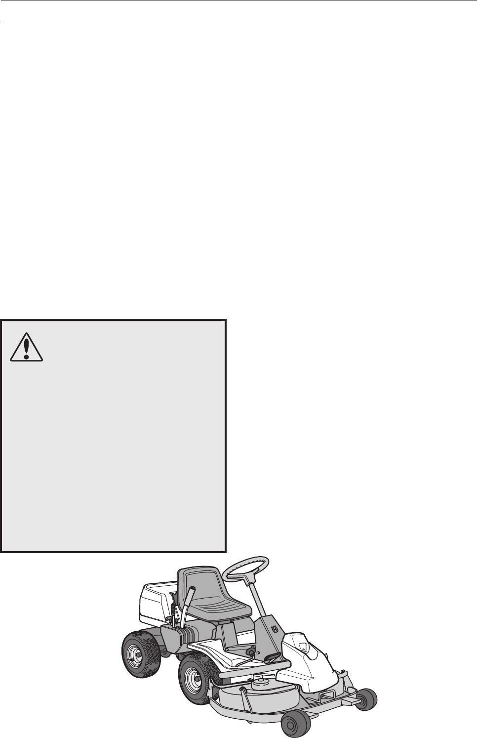
Rider 155
Please read these instructions carefully and make sure
you understand them before using the machine. English


English – 1
Operator’s Manual for
Rider 155
CONTENTS
Safety rules for USA............................................ 2
Introduction ......................................................... 4
Travel and transport on public roads................ 4
Towing .............................................................. 4
Intended use .................................................... 4
Serial number................................................... 5
Explanation of symbols ...................................... 6
Safety instructions .............................................. 8
General use ..................................................... 8
Driving on slopes ........................................... 10
Children.......................................................... 11
Maintenance .................................................. 11
Transport ........................................................ 13
Presentation ...................................................... 14
Location of the controls .................................. 14
Throttle/Choke lever....................................... 15
Speed limiter .................................................. 15
Parking brake ................................................. 15
Cutting unit ..................................................... 16
Lift lever for cutting unit .................................. 16
Lever for adjustment of cutting height ............ 17
Seat................................................................ 17
Fuelling .......................................................... 17
Driving ................................................................ 18
Before starting................................................ 18
Starting the engine ......................................... 18
Driving the machine ....................................... 20
Cutting tips ..................................................... 21
Stopping the engine ....................................... 22
Release lever ................................................. 22
Maintenance ...................................................... 23
Maintenance schedule ................................... 23
Dismantling of the machine hoods ................. 24
Checking and adjusting the steering wires .... 25
Adjusting the parking brake ........................... 25
Adjustment of throttle wire ............................. 26
Inspecting the muffler ..................................... 26
Replacement of fuel filter ............................... 27
Replacement of air filter ................................. 27
Checking the level of the battery acid ............ 28
Ignition System .............................................. 29
Checking the safety system ........................... 30
Main fuse ....................................................... 31
Checking the tyre pressure ............................ 31
Checking the engine’s cooling air intake........ 31
Fitting the cutting unit ..................................... 32
Installing BioClip 90 ....................................... 33
Checking and adjustment of cutting unit’s
ground pressure ............................................. 33
Checking the cutting unit´s parallelism .......... 33
Adjusting the parallelism of the cutting unit.... 34
Removing the cutting unit .............................. 34
Replacing the cutting unit belts ...................... 35
Service position for cutting unit ...................... 36
Placing in service position .............................. 36
Restoring from service position ...................... 38
Checking the blades ...................................... 39
Replacing the break-pin (BioClip 90) ............. 40
Removal of BioClip plug (Combi) ................... 40
Lubrication......................................................... 41
Checking the engine’s oil level ....................... 41
Changing the oil ............................................. 41
Change of oil filter .......................................... 42
Checking the transmission’s oil level ............. 42
Lubricating the belt adjuster ........................... 42
General lubrication ......................................... 42
Trouble shooting schedule .............................. 43
Storage ............................................................... 44
Winter storage ................................................ 44
Cover ............................................................. 44
Service ........................................................... 44
Technical data ................................................... 45
Servicejournal ................................................... 44
IMPORTANT INFORMATION
Read carefully through the Operator’s manual so that you know how to use and maintain the
Rider before you use it.
For service measures other than those described in this manual, please contact an authorised
dealer that provides parts and service.

2 – English
These instructions are for your safety. Read them carefully.
Safe operation practices for ride-on mowers
IMPORTANT!
This cutting machine is capable of amputating hands and feet and throwing objects. Failure to
observe the following safety instructions could result in serious injury or death.
1. Safety rules for USA
I. General operation
1. Read, understand and follow all instructions in
the manual and on the machine before
starting.
2. Only allow responsible adults, who are familiar
with the instructions, to operate the machine.
3. Clear the area of objects such as rocks, toys,
wire, etc., which could be picked up and
thrown by the blade.
4. Be sure the area is clear of other people
before mowing. Stop the machine if anyone
enters the area.
5. Never carry passengers.
6. Do not mow in reverse unless absolutely
necessary. Always look down and behind
before and while backing.
7. Be aware of the mower discharge direction
and do not point it at anyone. Do not operate
the mower without either the entire grass
catcher or the guard in place.
8. Slow down before turning.
9. Never leave a running machine unattended.
Always turn off blades, set parking brake, stop
engine and remove keys before dismounting.
10. Turn off blades when not mowing.
11. Stop engine before removing grass catcher or
unclogging chute.
12. Mow only in daylight or good artificial light.
13. Do not operate the machine while under the
influence of alcohol or drugs.
14. Watch for traffic when operating near or
crossing roadways.
15. Use extra care when loading or unloading the
machine into a trailer or truck.
II. Slope operation
Slopes are a major factor related to loss-of-control
and tip-over accidents, which can result in severe
injury or death.
All
slopes require extra caution. If
you cannot back up the slope or if you feel uneasy
on it, do not mow it.
DO
Mow up and down slopes, not across.
Remove obstacles such as rocks, tree limbs,
etc.
Watch for holes, ruts or bumps. Uneven
terrain could overturn the machine.
Tall grass
can
hide obstacles.
Use slow speed. Choose a low gear so that
you will not have to stop or shift while on the
slope.
Follow the manufacturer’s recommendations
for wheel weights or counterweights to improve
stability.
Use extra care with grass catchers or other
attachments. These can change the stability of
the machine.
Keep all movement on the slopes
slow
and
gradual.
Do not make sudden changes in
speed or direction.
Avoid starting or stopping on a slope. If tires
lose traction, disengage the blades and
proceed slowly
straight
down the slope.
DO NOT
Do not turn on slopes unless necessary and
then, turn slowly and gradually downhill, if
possible.
Do not mow near drop-offs, ditches or
embandments. The mower could suddenly turn
over if a wheel is over the edge of a cliff or
ditch, or if an edge caves in.
Do not mow on wet grass. Reduced traction
could cause sliding.
Do not try to stabilize the machine by putting
your foot on the ground.
Do not use grass catcher on steep slopes.
III. Children
Tragic accidents can occur if the operator is not
alert to the presence of children. Children are often
attracted to the machine and the mowing activity.
Never
assume that children will remain where you
last saw them.
1. Keep children out of the mowing area and
under the watchful care of another responsible
adult.
2. Be alert and turn machine off if children enter
the area.
3. Before and when backing, look behind and
down
for small children.
4. Never carry children. They may fall off and be
seriously injured or interfere with safe machine
operation.
5. Never allow children to operate the machine.
6. Use extra care when approaching blind
corners, shrubs, trees or other objects that may
obscure vision.

English – 3
IV. Service
1. Use extra care in handling gasoline and other
fuels. They are flammable and vapours are
explosive.
a) Use only an approved container.
b) Never remove gas cap or add fuel with the
engine running. Allow engine to cool before
refuelling. Do not smoke.
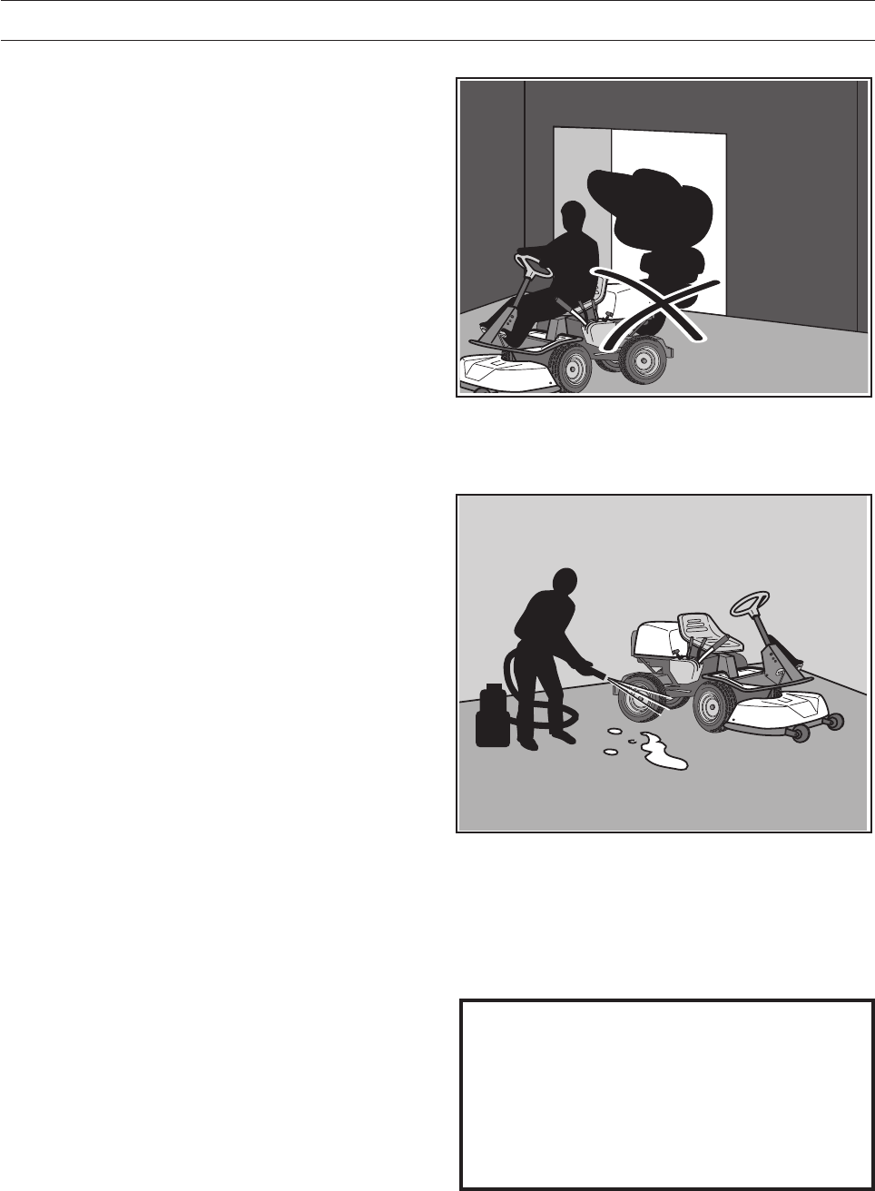
c) Never refuel the machine indoors.
d) Never store the machine or fuel container
inside where there is an open flame, such as
in a water heater.
2. Never run a machine inside a closed area.
3. Keep nuts and bolts, especially blade
attachment bolts, tight and keep equipment in
good condition.
4. Never tamper with safety devices. Check their
proper operation regularly.
5. Keep machine free of grass, leaves or other
debris build-up. Clean up oil or fuel spillage.
Allow machine to cool before storing.
6. Stop and inspect the equipment if you strike an
object. Repair, if necessary, before restarting.
7. Never make adjustments or repairs with the
engine running.
8. Grass catcher components are subject to wear,
damage and deterioration, which could expose
moving parts or allow objects to be thrown.
Frequently check components and replace with
manufacturer’s recommended parts, when
necessary.
9. Mower blades are sharp and can cut. Wrap the
blade(s) or wear gloves and use extra caution
when servicing them.
10. Check brake operation frequently. Adjust and
service as required.
Danger, keep hands and feet away
Travel and transport on public roads
Check the relevant road traffic regulations before
driving the machine on a public road. If transporting
the machine on another vehicle always use
approved securing devices and make sure that the
machine is securely held.
Towing
If your machine has a hydrostatic transmission you
should only tow it very short distances at low speed
if absolutely necessary, otherwise the transmission
may be damaged.
Intended use
This machine is designed solely for cutting grass
on conventional lawns and other cleared and
leveled ground without obstacles, as rocks, stumps
etc., and, in conjunction with accessories supplied
by the manufacturer even for other special tasks
for which instructions are delivered with the
accessory. Use in any other way is considered as
contrary to the intended use. Compliance with and
strict adherence to the conditions of operation,
service and repair as specified by the manufacturer
also constitute essential elements of the intended
use.
This machine should be operated, serviced and
repaired only by persons who are familiar with its
particular characteristics and who are acquainted
with the relevant safety procedures.
Accident prevention regulations, all other generally
recognised regulations on safety and occupational
medicine, and all road traffic regulations must be
observed at all times.
Any arbitrary modifications carried out to this
machine may relieve the manufacturer of liability
for any resulting damage or injury.
Safe operation practices for Ride-On Mowers
Before starting cutting operations, train different
driving operations on an open ground without
people nearby until you feel familiar with handling
the equipment. This is particularly important if you
have no or little prior experience of driving a
vehicle.
Data indicates that operators, age 60 years and
above, are involved in a large percentage of riding
mower-related injuries. These operators should
evaluate their ability to operate the riding mower
safely in order to protect themselves and others
from serious injury.
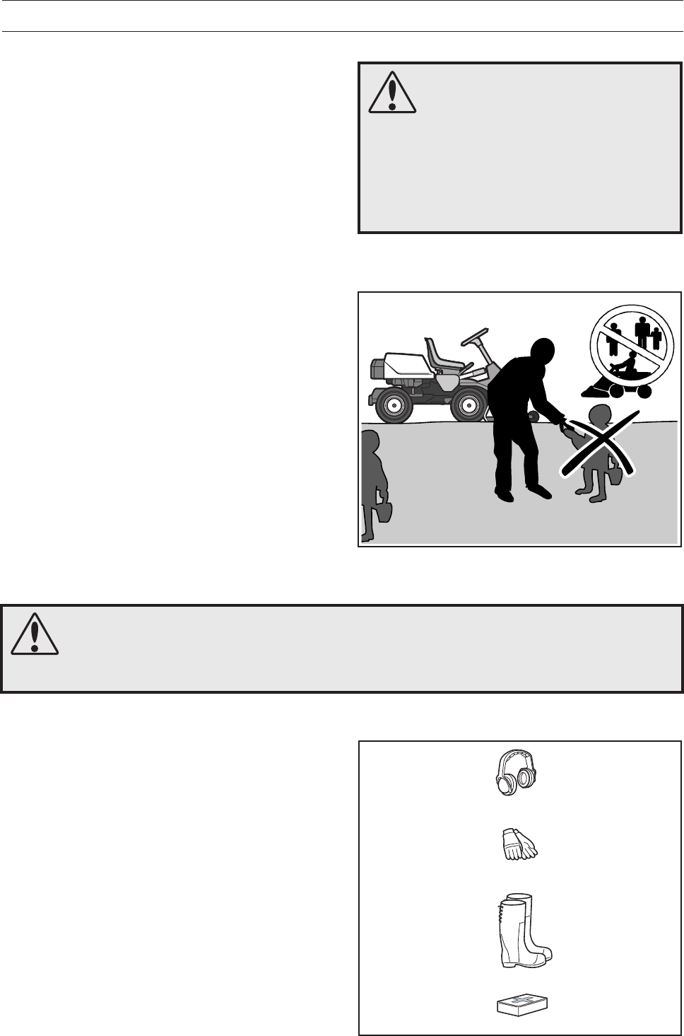
Never carry children, even with the blades off. They
may fall off and be seriously injured or interfere
with safe machine operation.
1. Safety rules for USA

4 – English
INTRODUCTION
Dear customer
Thank you for choosing a Husqvarna Rider. Husqvarna Riders are built to a unique design with a front-
mounted cutting unit and a patented rear-wheel steering system. Riders are designed for maximum efficiency
even in small or confined areas. Collected controls and a hydrostatic transmission controlled by pedals also
contribute to the machine’s performance.
We hope you will find this operator’s manual very useful. By following its instructions (on operation, service,
maintenance, etc.) you will significantly extend the life of the machine and even its second-hand value.
When you sell your Rider, make sure you pass on the operator’s manual to the new owner.
Travel and transport on public roads
Check the relevant road traffic regulations before driving the machine on a public road. If transporting the
machine on another vehicle always use approved securing devices and make sure that the machine is
securely held.
Towing
Your machine is equipped with a hydrostatic transmission and, if necessary, you should only tow the machine
over short distances and at a low speed, otherwise there is a risk of damaging the transmission.
Intended use
This machine has been designed to mow grass on lawns and other open and level ground surfaces without
obstacles such as stones, tree stubs, etc., even when the machine is equipped with special accessories
provided by the manufacturer, for which the operating instructions are provided in conjunction with delivery.
Use in any other way is considered as contrary to the intended use. Compliance with and strict adherence to
the conditions of operation, service and repair as specified by the manufacturer also constitute essential
elements of the intended use.
This machine should be operated, serviced and repaired only by persons who are familiar with its particular
characteristics and who are acquainted with the relevant safety procedures.
Accident prevention regulations, all other generally recognised regulations on safety and occupational
medicine, and all road traffic regulations must be observed at all times.
Any arbitrary modifications carried out to this machine may relieve the manufacturer of liability for any
resulting damage or injury.

English – 5
SAFETY INSTRUCTIONS
Good service
Husqvarna products are sold all over the world and only through servicing dealers. This is to ensure that you,
the customer, get the best support and service. Before the machine is delivered it undergoes inspection and
is adjusted by your dealer.
When you need spare parts or advice on service issues, warranty terms, etc., contact:
This Operator’s Manual belongs to
machine with serial number:
Serial number
The serial number can be found on the printed plate attached to the front, left-hand side under the seat.
Stated on the plate, from the top are:
• The machines type designation.
• The manufacturer’s type number.
• The machine’s serial number.
State the type designation and serial number when ordering spare parts.
The engine number is punched on the valve cover. The text states:
• Model.
• Type.
• Code.
Please state these when ordering spare parts.
The transmission’s serial number is stated on the barcode decal located on the front of the housing on the
left-hand drive axle:
• Type designation is stated above the barcode and starts with the letter “K”.
• The serial number is stated above the barcode and has the prefix “s/n”.
• The manufacturer’s type number is stated under the barcode and has the prefix “p/n”.
State the type designation and serial number when ordering spare parts.
Engine Transmission
6 – English
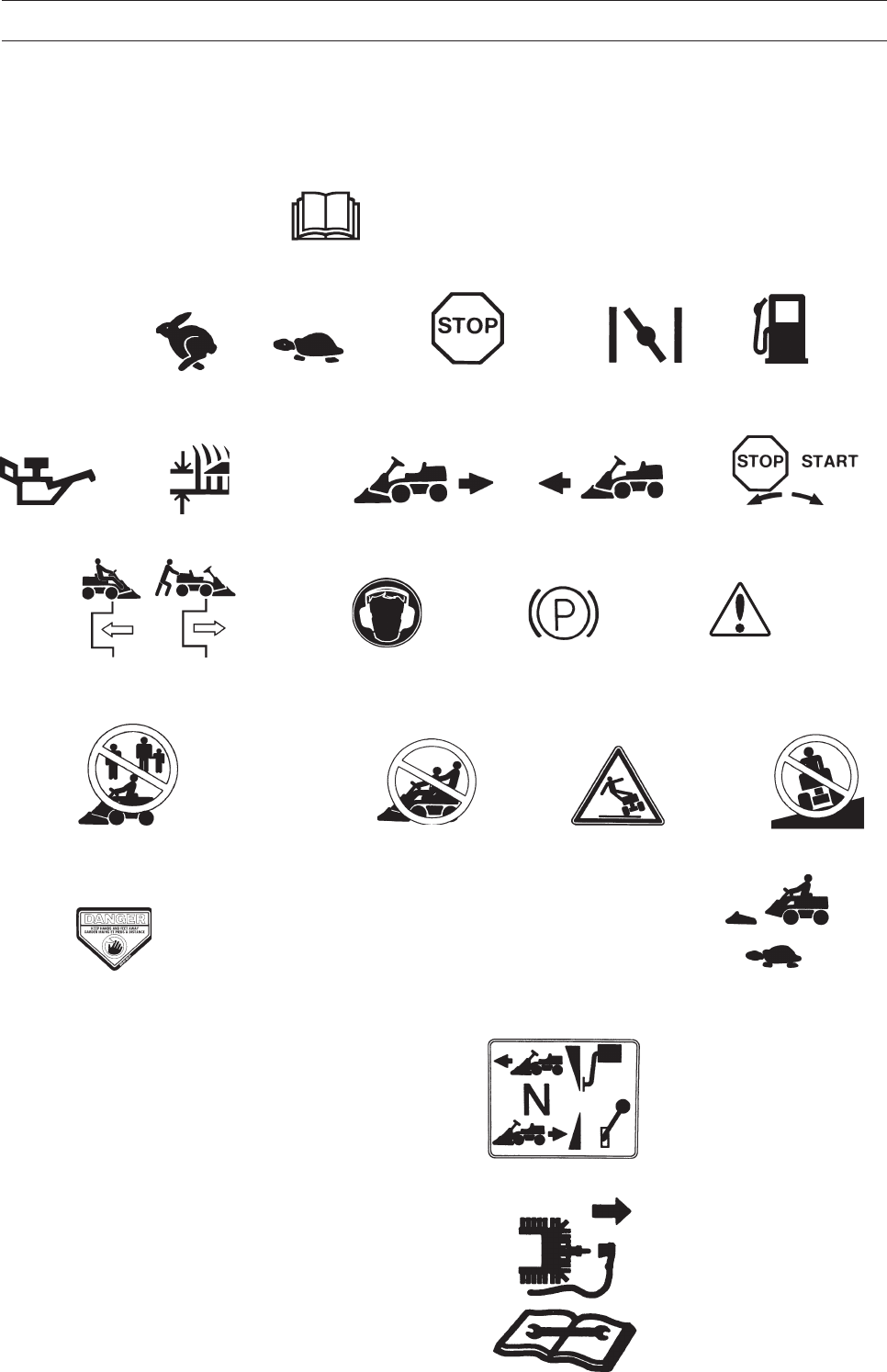
These symbols are on the machine and in the operator’s manual.
Study them carefully so that you know what they mean.
Read the operator’s manual
Neutral Fast Slow Engine off Choke Fuel
Oil level Cutting height Backwards Forwards Ignition
Hydrostatic free wheel Use eye and hearing protection Parking brake Warning
Never use the machine if persons, especially
children, or animals, are in the vicinity.
Drive very slowly
without the cutting unit.
N
EXPLANATION OF SYMBOLS
Speed limiter pedal forwards
Neutral
Speed limiter pedal reverse
Switch off the engine and take off
the ignition cable before repairs or
maintenance
Never carry passengers on the
machine or equipment. Warning!
Risk that the
machine can tip over
Never drive across a
slope
STARTING INSTRUCTION
• READ OPERATOR´S MANUAL.
• CHECK ENGINE OIL LEVEL.
• ENGAGE PARKING BRAKE AND LIFT
CUTTING DECK IN TRANSPORT POSITION.
• IF ENGINE IS COLD USE CHOKE.
• START THE ENGINE.
• RELEASE PARKING BRAKE BEFORE DRIVING.
INSTRUCTIONS DE DEMARRAGE
• LIRE LE GUIDE DE CONDUITE.
• VÉRIFIEZ LE NIVEAU D´HUILE MOTEUR.
• SERREZ LE FREIN DE PARKING ET METTRE LE CARTER
DE COUPE EN POSITION HAUT.
• SI LE MOTEUR EST FROID, UTILISEZ LE STARTER.
• ACTIONNEZ LE DÉMARREUR.
• DESSERREZ LE FREIN DE PARKING
Keep hands and feet away from
moving parts.
English – 7
EXPLANATION OF SYMBOLS
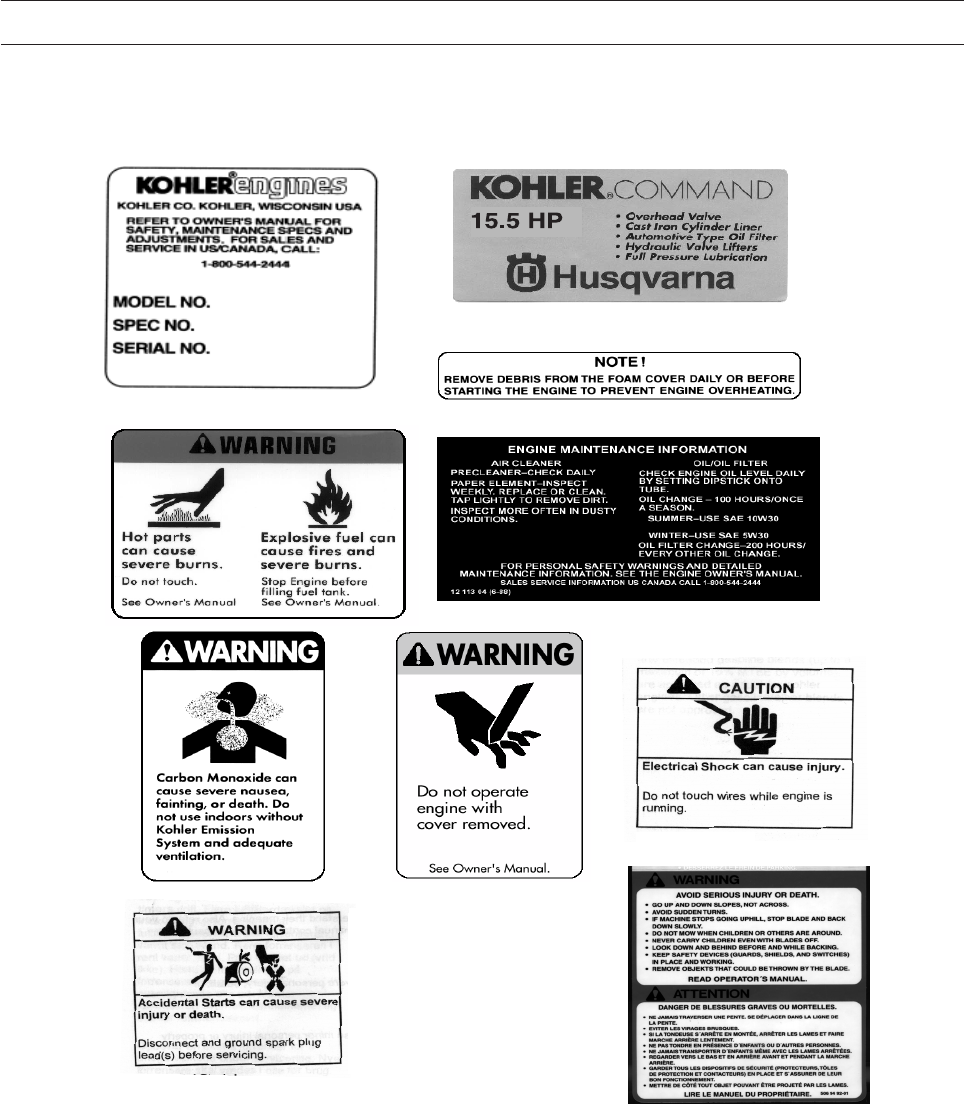
8009-442
Placards
8 – English
8010-047
6003-002
8010-052
Safety instructions
These instructions are for your safety. Read them carefully.
General use
•Read all the instructions in this operator’s
manual and on the machine before you start it.
Ensure you understand them and then observe
them.
•Learn how to use the machine and its controls
safely and learn to how to stop quickly. Also
learn to recognize the safety decals.
•Only allow the machine to be used by adults
who are familiar with its use.
•Make sure nobody else is in the vicinity of the
machine when you start the engine, engage the
drive or drive off.
•Make sure animals and people maintain a safe
distance from the machine.
•Stop the machine if anyone enters the working
area.
•Clear the area of objects such as stones, toys,
wires, etc. that may become caught in the blades
and be thrown out.
•Look out for the ejector and do not direct it
towards anyone.
•Stop the engine and prevent it from starting
before you clean the cutting unit.
•Remember the operator is responsible for
danger or accidents.
•Never carry passengers. The machine is only
intended to be used by one person.
•Always look downwards and backwards before
and while reversing. Keep watch for both large
and small obstacles.
•Slow before cornering.
•Switch off the blades when you are not mowing.
SAFETY INSTRUCTIONS
WARNING!
This machine can sever hands and feet as well as throw objects.
Failure to observe the safety instructions can result in serious injuries.
WARNING!
The inserted symbol means that important safety instructions need to be observed. It
applies to your safety.
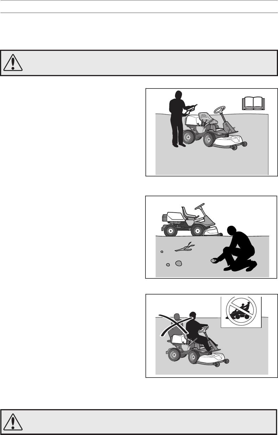
Never carry passengers.
Read the operator’s manual before starting the machine.
Clear the area of objects before mowing.
English – 9
6003-006
8011-292
•Take care when rounding a fixed object, so that
the blades do not hit it. Never run the machine
over foreign objects.
•Only use the machine in daylight or in other
well-lit conditions. Keep the machine at a safe
distance from holes or other irregularities in the
ground. Pay attention to other possible risks.
•Never use the machine if you are tired, if you
have consumed alcohol, or if you are taking
other drugs or medication that can affect your
vision, judgment or co-ordination.
•Keep an eye on the traffic when working close to
a road or when crossing it.
•Never leave the machine unsupervised with the
engine running. Always stop the blades, apply
the parking brake, stop the engine and remove
the keys before leaving the machine.
•Never allow children or other persons not
trained in the use of the machine to use or
service it. Local laws may regulate the age of
the user.
SAFETY INSTRUCTIONS
WARNING!
Engine exhaust, some of its
constituents and certain vehicle
components contain or emit
chemicals considered to cause
cancer, birth defects or other
reproductive impairment. The
engine emits carbon monoxide,
which is a colourless, poisonous
gas. Do not use the machine in
enclosed spaces.
WARNING!
You must use approved personal protective equipment whenever you use the ma-
chine. Personal protective equipment cannot eliminate the risk of injury but it will
reduce the degree of injury if an accident does happen. Ask your dealer for help in
choosing the right equipment.
•Make sure that you have first aid equipment
close at hand when using the machine.
•Never use the machine when barefoot. Always
wear protective shoes or protective boots,
preferably with steel toes.
•Wear approved protective glasses or full-face
visor during assembly and when operating.
•Never wear loose fitting clothes that can catch in
moving parts.
Keep children away from the area to be mowed.
Personal protective equipment.
10 – English
8010-054
6003-004
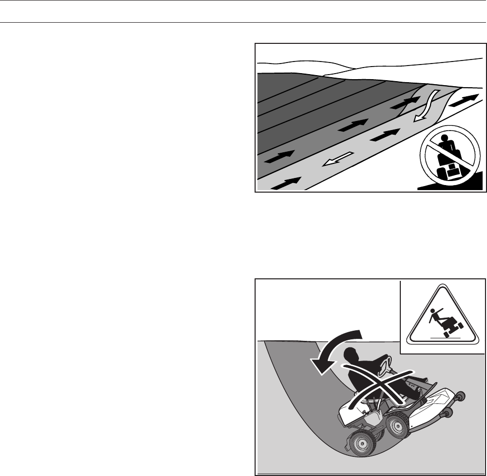
Be especially careful when driving on slopes.
Mow upwards and downwards on slopes, not sideways.
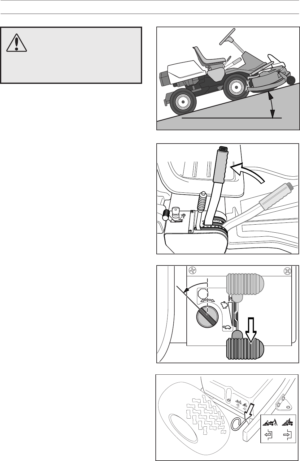
Driving on slopes
Driving on slopes is one of the operations where
the risk of the driver losing control of the machine or
of it overturning is the greatest; this can result in
serious injury or death. All slopes demand extra
care. If you cannot reverse up a slope or if you feel
unsure, do not mow it.
Proceed as follows:
• Remove obstacles such as stones, branches,
etc.
•Mow upwards and downwards, not sideways.
•Do not use the machine on ground that slopes
more than 15°.
•Avoid starting or stopping on a slope. If the tyres
start to slip, stop the blades and drive slowly
down the slope.
•Always drive smoothly and slowly on slopes.
•Do not make any sudden changes in speed or
direction.
•Avoid unnecessary turns on slopes, if
necessary, turn slowly and gradually downwards
if possible.
•Watch out for and avoid driving over furrows,
holes and bumps. It is easier for the machine to
overturn on uneven ground. Tall grass can hide
obstacles.
•Drive slowly. Do not turn the wheel sharply. The
machine engine-brakes better in low gear.
•Take extra care if any attachments are fitted that
can change the stability of the machine.
•Do not mow too close to edges, ditches or
banks. The machine can suddenly overturn if
one wheel comes over the edge of a steep slope
or a ditch, or if an edge gives way.
•Do not mow wet grass. It is slippery, and the
tyres can lose their grip so that the machine
skids.
•Do not try to stabilize the machine by putting
your foot on the ground.
•When cleaning under the machine, it may never
be driven near verges or ditches.
•Follow the manufacturer’s recommendations
regarding wheel weights or counterbalance
weights to increase stability.
SAFETY INSTRUCTIONS
English – 11
8010-057
8010-058
Children
•Serious accidents may occur if you fail to be on
your guard for children in the vicinity of the
machine. Children are often attracted to the
machine and mowing. Never assume that
children will remain where you last saw them.
•Keep children away from the area to be mowed
and under close supervision by another adult.
•Keep an eye out and shut off the machine if
children enter the work area.
•Before and during reversing procedures, look
behind you and down for small children.
•Never allow children to ride along. They can fall
off and seriously injure themselves or be in the
way for safe manoeuvring of the machine.
•Never allow children to operate the machine.
•Be particularly careful near corners, bushes,
trees or other objects that block your view.
SAFETY INSTRUCTIONS
Never allow children to operate the machine.
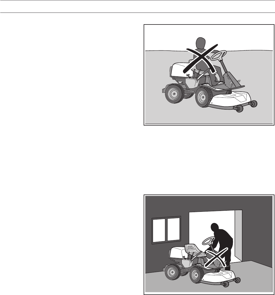
Never fill the fuel tank indoors.
Maintenance
•Stop the engine. Prevent starting by removing
the ignition cable from the spark plug or remove
the ignition key before making any adjustments
or carrying out maintenance.
•Never fill the fuel tank indoors.
•Petrol and petrol fumes are poisonous and
extremely flammable. Be especially careful when
handling petrol, as carelessness can result in
personal injury or fire.
•Only store fuel in containers approved for the
purpose.
•Never remove the fuel cap and fill the petrol
tank while the engine is running.
•Allow the engine to cool before refuelling. Do
not smoke. Do not fill petrol in the vicinity of
sparks or naked flames.
12 – English
WARNING!
The engine and the exhaust
system become very hot during
operation.
Risk of burn injuries if touched.
WARNING!
The battery contains lead and
lead pollutants, chemicals that
are considered to cause cancer,
birth defects or other repro-
ductive impairment. Wash your
hands after touching the battery.
•If leaks arise in the fuel system, the engine must
not be started until the problem has been
resolved.
•Store the machine and fuel in such a way that
there is no risk that leaking fuel or fumes can
cause any damage.
•Check the fuel level before each use and leave
space for the fuel to expand, because the heat
from the engine and the sun may otherwise
cause the fuel to expand and overflow.
•Avoid overfilling. If you spill petrol on the
machine, wipe up the spill and wait until it has
evaporated before starting the engine. If you spill
petrol on your clothing, change your clothing.
•Allow the machine to cool before performing any
actions in the engine compartment.
•Be especially careful when handling battery
acid. Acid on the skin can cause serious
corrosive injuries. In the event of spillage on the
skin wash immediately with water.
•Acid in the eyes can cause blindness, contact a
doctor immediately.
•Take care with battery maintenance. Explosive
gases form in the battery. Never perform
maintenance on the battery while smoking or in
the vicinity of open flames or sparks. This can
cause the battery to explode and cause serious
injuries.
•Make sure all nuts and bolts are tightened
correctly and that the equipment is in good
condition.
•Do not modify safety equipment. Check regularly
to be sure it works properly. The machine must
not be driven if protective plates, protective
covers, safety switches or other protective
devices are not fitted or are defective.
•Do not change the setting of governors and
avoid running the engine at excessively high
revs. If you run too fast, you risk damaging the
machine components.
• Observe the risk of injury caused by moving or
hot parts if the engine is started with the engine
cover opened or the protective covers removed.
SAFETY INSTRUCTIONS
Do not smoke when carrying out maintenance.
8009-441
English – 13
8010-060
8010-061
SAFETY INSTRUCTIONS
•Never use the machine indoors or in spaces
lacking proper ventilation. Exhaust fumes
contain carbon monoxide, an odourless,
poisonous and highly dangerous gas.
•Stop and inspect the equipment if you run over
or into anything. If necessary, make repairs
before starting.
•Never make adjustments with the engine
running.
•The machine is tested and approved only with
the equipment originally provided or
recommended by the manufacturer.
•The blades are sharp and can cause cuts. Wrap
the blades or wear protective gloves when
handling them.
•Check regularly that the parking brake works.
Adjust and maintain as required.
•The mulching unit should only be used where
better quality mowing is required and in known
areas.
•Reduce the risk of fire by removing grass, leaves
and other debris that may have fastened on the
machine. Allow the machine to cool before
putting it in storage.
Transport
•The machine is heavy and can cause serious
crush injuries. Be especially careful when it is
loaded in or out of a car or on and off of a trailer.
•Use an approved trailer to transport the ma-
chine. Activate the parking brake and secure the
machine using approved fasteners, such as
tension belts, chains or ropes when transporting.
•Check and observe local road traffic regulations
before transporting or driving the machine on
roads.
IMPORTANT INFORMATION
The parking brake is not sufficient to lock
the machine during transport. Ensure you
secure the machine firmly to the
transporting vehicle. Reverse the machine
on to the transporting vehicle to prevent it
from overturning.
Regularly clean grass, leaves and other debris from the
machine.
Never run the machine in an enclosed area.
14 – English
Presentation
Congratulations on your choice of a top quality
product which you will enjoy for many years.
These instructions describe the Rider 155. This
rider mower is equipped with a 15.5 horsepower
Kohler engine.
PRESENTATION
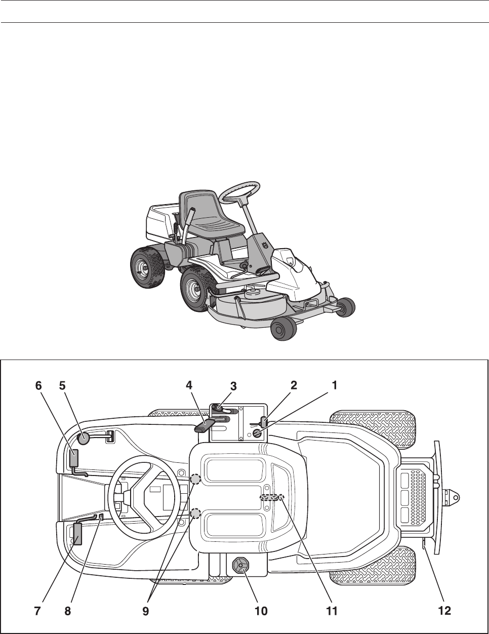
Location of the controls
1. Ignition lock
2. Throttle/Choke lever
3. Adjustment of cutting height
4. Lifting lever, cutting unit
5. Speed limiter for reversing
6. Speed limiter for driving forwards
7. Parking brake
8. Lock button for parking brake
9. Knobs for adjusting seat
10. Fuel tank cap
11. Main lock (under seat)
12. Lever for disengagement of drive
The power transmission from the engine is handled
by a hydrostatic gearbox, which allows variable
variation of the speed by using the pedals.
There is one pedal for driving forwards and one
pedal for reversing.
English – 15
PRESENTATION
Throttle and Choke lever
The engine speed is adjusted with the throttle
control, and thereby also the rotation speed of the
blades.
The control is also used to activate the choke
function. When the choke is used the engine
receives a richer mixture of fuel and air, which
simplifies cold start.
1
2
21
WARNING!
Make sure that branches do not
obstruct the pedals when mowing
under bushes, otherwise you may
lose control.
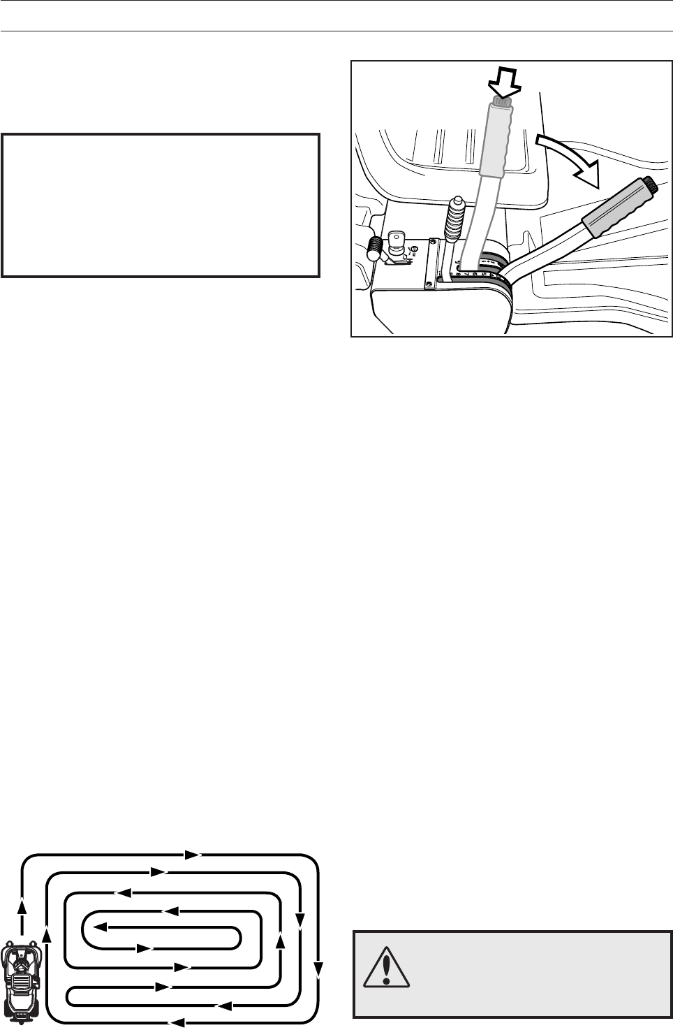
Parking brake
The parking brake is activated as follows:
1. Press down the parking brake pedal (1).
2. Press in the lock button (2) on the steering
column.
3. Release the parking brake pedal while keeping
the button pressed in.
The parking brake lock is automatically disengaged
when the parking brake pedal is pressed down.
Speed limiter
The speed of the machine is steplessly regulated
with two pedals. Pedal (1) is used to drive forwards
and pedal (2) for reversing.
6004-004H
6017-214A
6017-011
16 – English
PRESENTATION
Cutting unit
The Rider 155 can be fitted with four different
cutting units.
BioClip - 900 mm/36"
Combi - 1120 mm/44"
Combi - 1030 mm/41"
See ”Maintenance \ Checking the Blades” for
identification of the cutting unit.
Lifting of the cutting unit (transport position)
Lowering of the cutting unit (cutting position)
Lift lever for the cutting unit
The lift lever is used to set the cutting unit in trans-
port or cutting position.
If the lever is pulled back the unit will lift up and the
blades will automatically stop rotating (transport
position).
If the lock button is pressed and the lever is moved
forward the unit will be lowered and the blades will
automatically start rotating (cutting position).
The lever can also be used to temporarily regulate
the cutting height, e.g. for a small mound in the
lawn.
6017-214
6004-011H
6004-012H
English – 17
PRESENTATION
Fuelling
The engine should be run on 85 octane (or higher)
unleaded petrol/gasoline (no added oil).
Environmentally adapted alkylate fuel is also
recommended.
Do not use petrol that contains methanol.
Do not fill the tank completely, leave an expansion
area of at least 2.5 cm (1").
Seat
The seat has a jointed attachment on the front
edge and can be tipped forward.
The seat can also be adjusted lengthways.
Release the knobs under the seat and adjust it
forwards or backwards to the required position.
Lock the setting with the knobs.
Lever for adjustment of cutting height
With this lever the cutting height can be adjusted to
9 different positions.
Combi, 40-90 mm
(1 9/16" - 3 9/16")
BioClip unit, 45-95 mm
(1 3/4" - 3 3/4")
WARNING!
Petrol/gasoline is highly
inflammable. Observe care and
fill up with fuel outdoors (see
safety instructions).
6004-013H
6004-014H
6004-015
18 – English
Before starting
• Read the safety instructions and information on
the location and function of the controls before
starting (see pages 5-14).
• Conduct daily maintenance before starting (see
maintenance schedule on page 20).
DRIVING
Cold engine:
3. Push the throttle control to position 3 (choke
position). In this position the engine receives a
richer mixture so that the engine starts more
easily.
1
2
12
3
6007-001H
6017-011
6007-004H
8009-431
IMPORTANT INFORMATION
The air intake grille in the engine cover
behind the driver’s seat must not be
blocked by, for example, clothing, leaves,
grass or dirt.
Impaired cooling of the engine. Risk of
major engine damage.
Starting the engine
1. Lift up the cutting unit by pulling the lever
backwards to locked position (transport posi-
tion).
2. Apply the parking brake. This is done as follows:
• Press down the parking brake pedal (1).
• Press in the lock button on the steering
column (2).
• Release the parking brake pedal while
keeping the button pressed in.
The parking brake lock is automatically disengaged
when the parking brake pedal is pressed down.
English – 19
DRIVING
Warm engine:
4. Set the throttle control midway between position
1 and 2.
WARNING!
Never run the engine indoors, in
enclosed or poorly ventilated
areas. The exhaust fumes contain
toxic carbon monoxide.
6. When the engine has started release the ignition
key to neutral position.
Push the throttle control to the required speed.
For cutting 3/4 to full throttle.
IMPORTANT INFORMATION
Do not run the starter for more than about
10 seconds at a time. If the engine does
not start, wait about 60 seconds before
trying again.
5. Turn the ignition key to start position.
12
3
STOP START
STOP START
6007-005H
6007-006
6007-007
20 – English
DRIVING
Driving the machine
1. Release the parking brake by pressing down the
parking brake pedeal and then releasing it.
3. Select the required cutting height (1-9) with the
cutting height lever.
To obtain a uniform cutting height it is important
that the tyre pressures are equal on both front
wheels 60 kPa/8.5 PSI.
21
2. Carefully press down one of the pedals until the
correct speed is reached.
To drive forwards: press down pedal (1).
To reverse: press down pedal (2).
6017-012
6017-214A
6007-008H
English – 21
Mowing pattern
DRIVING
4. Push in the lock button on the lift lever and
lower down the cutting unit.
WARNING!
Clear the lawn from stones and
other object which can be thrown
out by the blades.
Cutting tips
• Localise and mark stones and other fixed
objects to avoid collision.
• Start with a high cutting height and reduce down
until the required cutting result are obtained.
• The cutting results are best with a high engine
speed (fast rotating blades) and low driving
speed (slow moving machine). If the grass is not
too high and thick, the driving speed can be
increased without noticeably depreciating the
mowing result.
• The best lawns are achieved if the grass is cut
often. Mowing becomes more uniform and the
grass cuttings become more evenly distributed
over the surface. The total time consumption is
not greater since it is possible to select a higher
driving speed without inferior mowing results.
• Avoid mowing a wet lawn. The mowing results
are inferior since the wheels sink down into the
soft lawn.
• Wash down the underside of the cutting unit with
water after use. Do not use a high pressure jet.
Put the cutting unit in the service position while
doing this.
• If you use the BioClip unit it is important to mow
the grass regularly.
IMPORTANT INFORMATION
The service-life of the drive belts
increases considerably if the engine is
run at low speed when engaging the
blades. For this reason do not increase
the throttle until the cutting unit has been
lowered to the cutting position.
6007-212
6007-009H
22 – English
DRIVING
Stopping the engine
Preferably allow the engine to idle for a minute to
obtain normal working temperature before stopping
it if it has been working hard.
1. Lift up the cutting unit by pulling the lever back
to the end position.
STOP START
MAX 15
WARNING!
Never drive the machine on
ground with a slope of more than
15°. Mow slopes upwards and
downwards, never across. Avoid
sudden changes in direction.
Release lever
The release control must be pulled out in order for
the Rider to be moved when the engine is shutoff.
2. Pull back the throttle control and turn the ignition
key to the STOP position.
3. When the Rider is at a standstill, press down the
parking brake and push in the locking button.
6007-002
6007-014H
6007-015
6007-217H

English – 23
50 100
MAINTENANCE
25
WARNING!
No service procedures must be conducted on the engine or cutting unit unless:
•The engine is switched off.
•The ignition key is removed.
•The ignition cable is removed from the plug.
•The parking brake is applied.
•The cutting unit is disengaged.
Maintenance schedule
The following is a list of the maintenance which should be conducted on the machine. For the items which
are not described in these instructions go to an authorised service workshop.
Daily
maintenance
before start
●= Described in these instructions.
❍= Not described in these instructions.
Maintenance Page
Maintenance interval
in hours
1) First change after 5 hours. Replace after every 25 hours with heavy loads or high temperatures.2) During dusty conditions cleaning
and replacement should be more frequent. 3) For daily use of the machine lubrication should be conducted twice a week. 4) Conducted
by authorised service workshop.
Check the engine’s oil level 41 ●
Check the engine’s cooling air inlet 31 ●
Check the fuel pump’s air filter 27 ●
Check the steering wires 25 ●
Check the battery 28 ●
Check the safety system 30 ●
Check screws and nuts – ❍
Check for fuel and oil leakage – ❍
Clean around the silencer – ❍
Check the muffler 26 ●
Change the engine oil 1) 41 ●1) ●1)
Replace the air filter’s prefilter 2) 27 ●
Check the cutting unit 33 ●
Check the tyre pressures 60 kPa//8.5 PSI 31 ●
Lubricating the belt adjuster 3) 42 ●
Lubricate joints and shafts 3) 42 ●
Check the V-belts – ❍
Check the hydrostat’s cooling fins – ❍
Check the transmission’s oil level 42 ●
Adjust the parking brakes 25 ●
Check and adjust the throttle wire 26 ●
Clean the engine’s and hydrostat’s cooling flanges 2,4) –❍
Replace the air filter’s pre-filter and paper filter 2) 27 ●
Replace the fuel filter 27 ●
Replace the plug 29 ●
24 – English
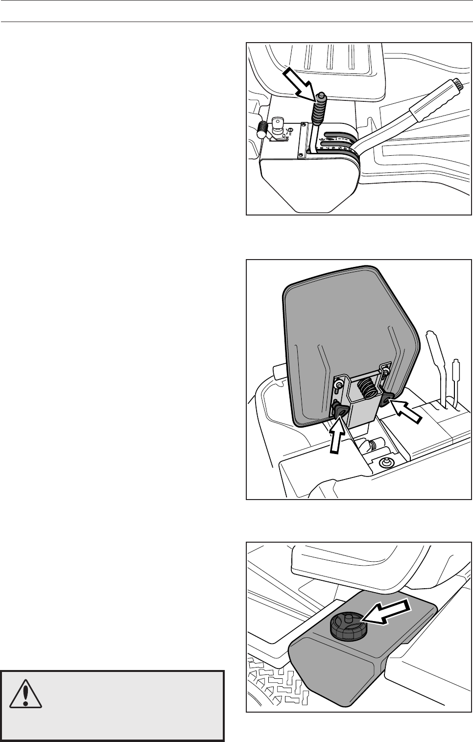
Dismantling of the machine hoods
Engine hood
The engine is accessible for servicing when the
engine hood is lifted up.
Tilt the seat forward, release the rubber strap under
the seat, and tilt the hood backwards.
MAINTENANCE
Left-hand fender
Release the screws in the fender (2) and lift off the
fender.
Right-hand fender
Remove the knob (1), the screws (2 and 3) and lift
off the fender.
Front hood
Release the clip on the front hood and lift off the
hood.
2
11
3
1
6008-001
6017-215
6017-003
6017-013
English – 25
Checking and adjustment of the
steering wires
The steering is controlled by means of wires.
These can in time become slack, which implies that
the adjustment of the steering becomes altered.
Check and adjust the steering as follows:
1. Dismantle the frame-plate by releasing the
screws (two on each side).
MAINTENANCE
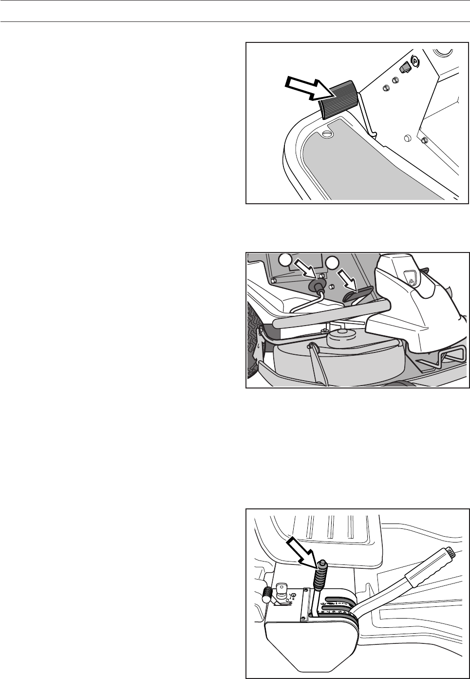
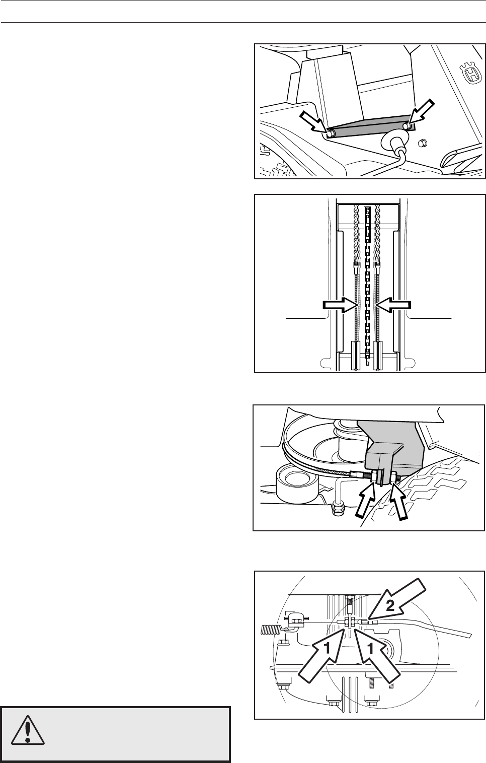
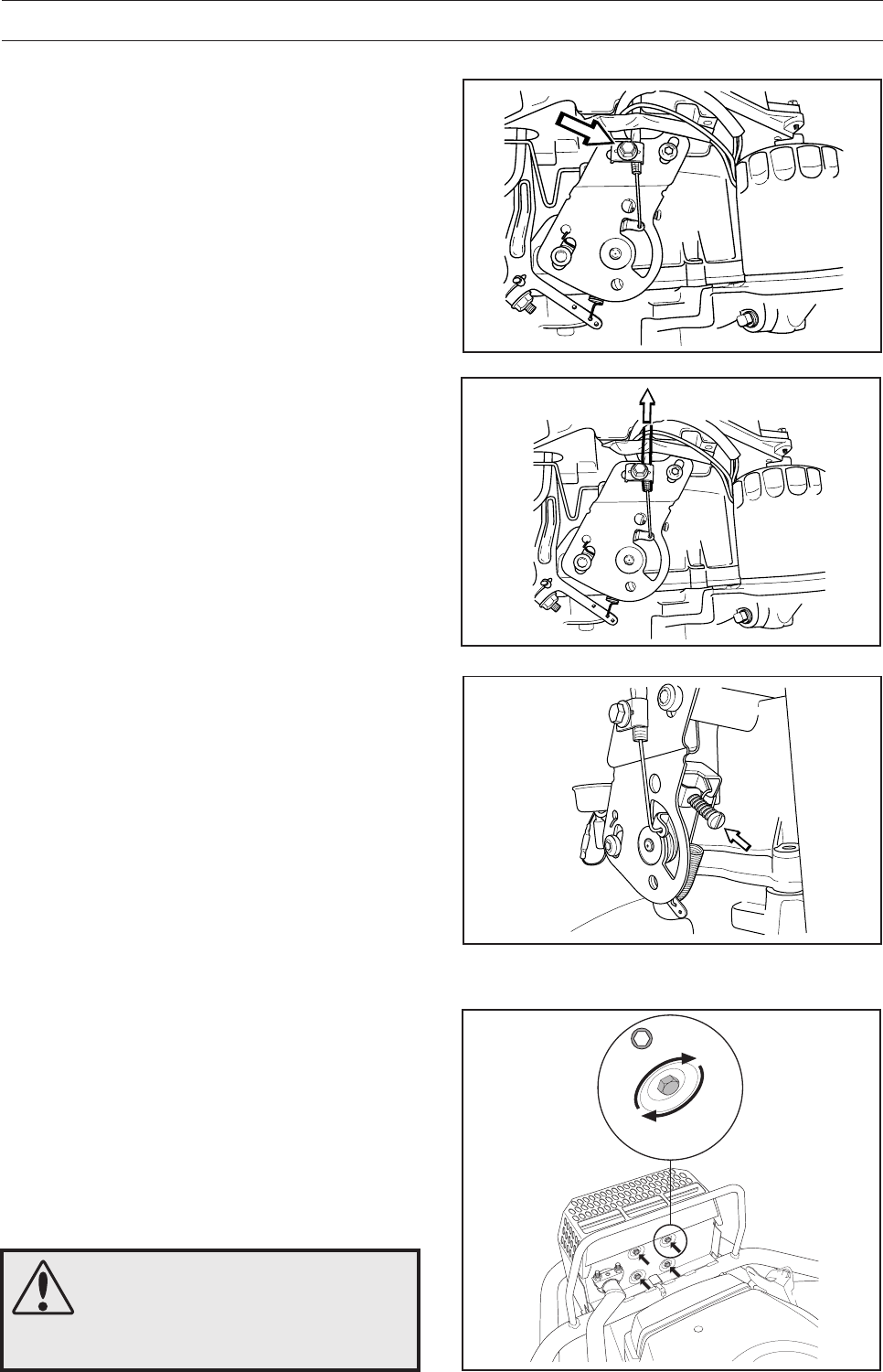
Adjusting the parking brake
The parking brake is adjusted as follows:
1. Loosen the locking nuts (1).
2. Tension the cable using the adjuster screw (2)
until the play in the cable is taken up.
3. Tighten the locking nuts (1).
4. The parking brake should be checked again
after the adjustment has been made.
WARNING!
A poorly adjusted parking brake
can result in reduced braking
ability.
3. If necessary, the wires can be adjusted by
tightening the adjuster nuts on each side of the
steering collar. Do not tension the wires too
much, they should only be
tightened
against the
steering collar.
Support the wire so it does not twist.
If you tension only one side the steering wheel’s
centre position may change.
Check the wire tension as set out in point 2
after you have made the adjustment.
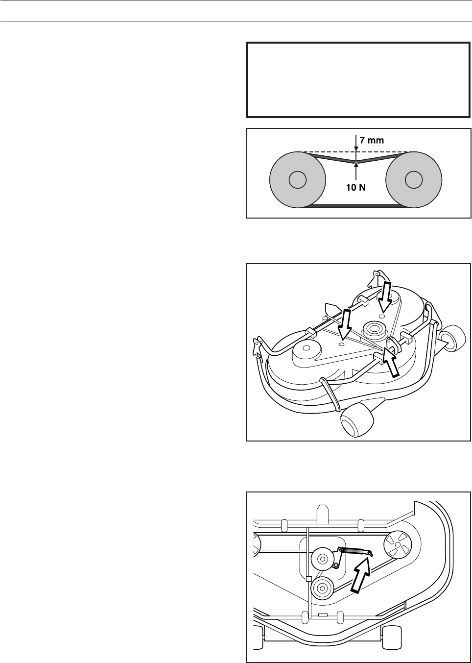
2. Check the tension of the steering wires by
pushing them together as shown in the dia-
gram. It should be possible to push them
together so that the distance between them is
half as much, without using unnecessary force.
RIDER 850
RIDER 850
6008-008H
6008-009
6008-010
6008-239H
26 – English
MAINTENANCE
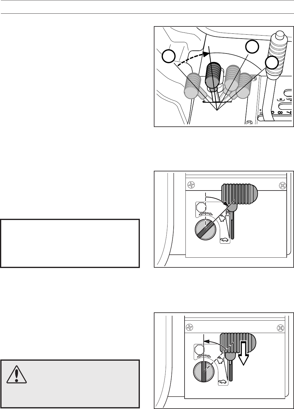
Adjusting the throttle wire
If the engine does not respond as it should do when
the throttle lever is moved or if the top speed is not
reached, the throttle wire may need adjusting.
1. Loosen the clamping screw (by the arrow), and
slide the throttle to the choke position.
2. Pull the throttle wire’s casing as far as possible
to the right and check that the choke is fully
actuated.
3. Tighten the clamping screw.
4. Pull back the throttle to the full throttle position
and check that the choke is no longer actuated.
8009-685
~ 10Nm
10mm
Inspecting the muffler
Check regularly that the muffler is complete and
secured correctly.
Temperature variations and vibrations can mean
that the tightening torque for the screws drops. The
screws should be checked when servicing to
guarantee the correct torque. The tightening torque
should be about 10 Nm. Never use a defective
muffler.
WARNING!!
The muffler gets very hot in use
and remains so for a short time
afterwards. Contact can result in
burns. Remember the risk of fire.
8009-455
8009-469
8009-456
English – 27
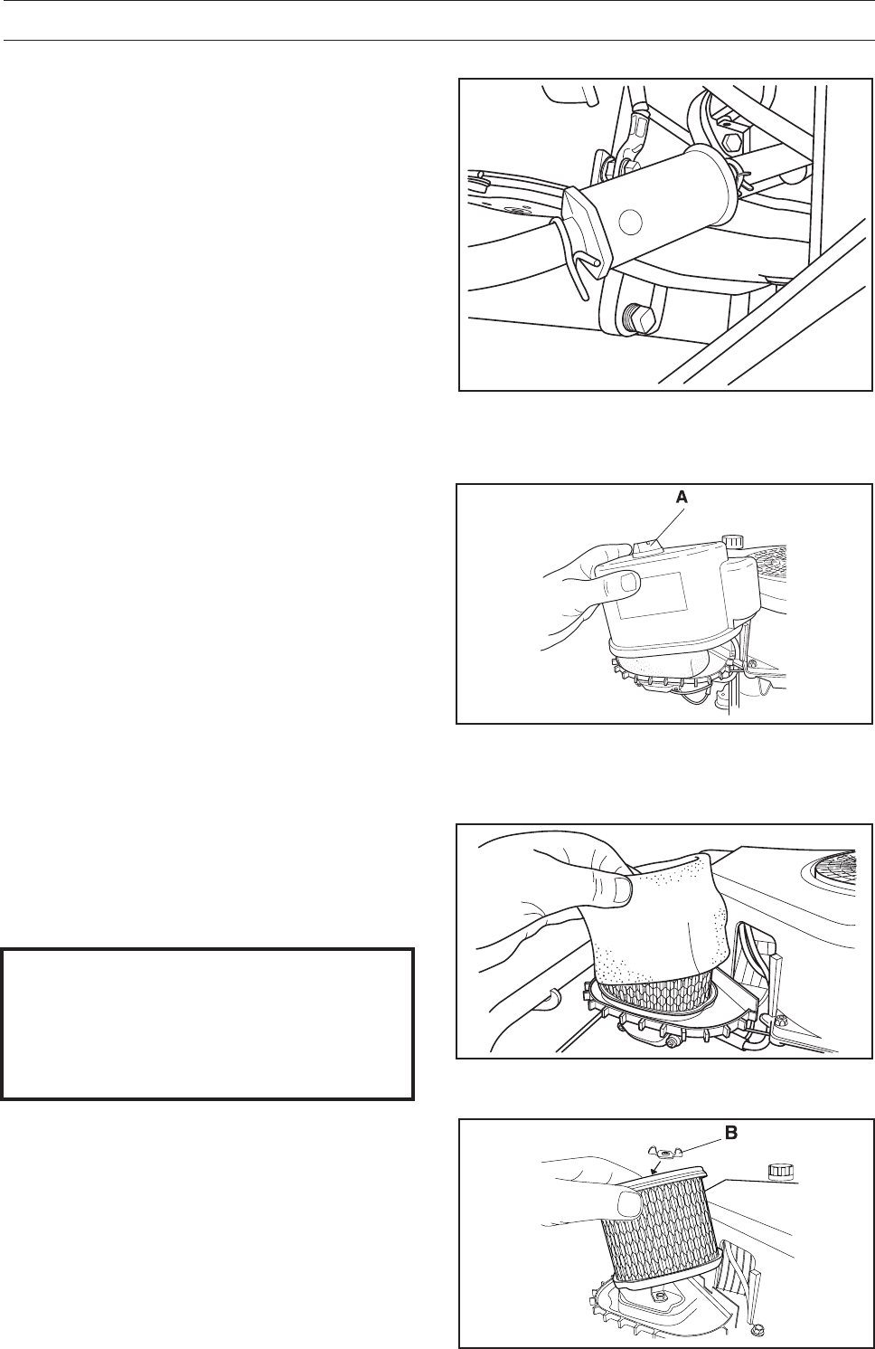
Replacing the air filter
If the engine seems to lack power or goes
irregularly the reason may be that the air filter is
clogged.
It is therefore important to replace the air filter at
regular intervals (see ”Maintenance schedule” for
correct service interval).
1. Fold open the engine cover.
Unscrew the wing nut (A) on top of the air filter and
remove the cover.
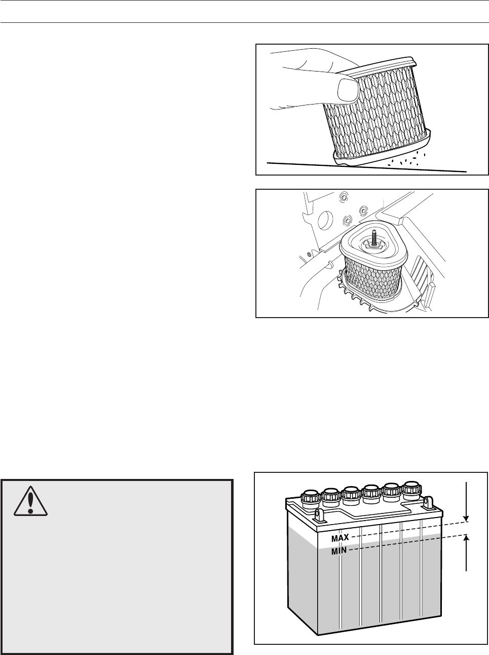
3. Carefully remove the precleaner. Wash and
reoil the precleaner every 25 hours of opera-
tion. Wash the precleaner in warm water with
detergent. Rinse precleaner with clear warm
water. Squeeze water out (do not wring to
avoid tearing). Allow to dry before lightly oiling
with fresh engine oil and installing it over the
paper filter.
IMPORTANT INFORMATION
Do not use compressed air to clean the
paper filter.
Filters should not be oiled. They should be
assembled dry.
4. Replace the paper filter every 100 hours or if it
is clogged with dirt. Unscrew the wing nut (B)
and remove the paper filter.
MAINTENANCE
Replacement of the fuel filter
Replace the pipe fitted fuel filter every 100 running
hours (once per season) or more frequently if it is
clogged.
Replace the filter as follows:
1. Fold open the engine cover.
2. Move the hose clips away from the filter. Use a
pair of flat pliers.
3. Pull off the filter from the hose ends.
4. Press in the new filter on the hose ends. If
necessary soap solution can be applied on the
filter ends to simplify fitting.
5. Push the hose clips back on the filter.
8009-458
8009-459
8009-460
8009-457
28 – English
MAINTENANCE
WARNING!
Procedures on contact with acid
External: Rinse well with plenty of water.
Internal: Drink large quantities of water or
milk. Contact a doctor as soon as
possible.
Eyes: Rinse well with plenty of water.
Contact a doctor as soon as possible.
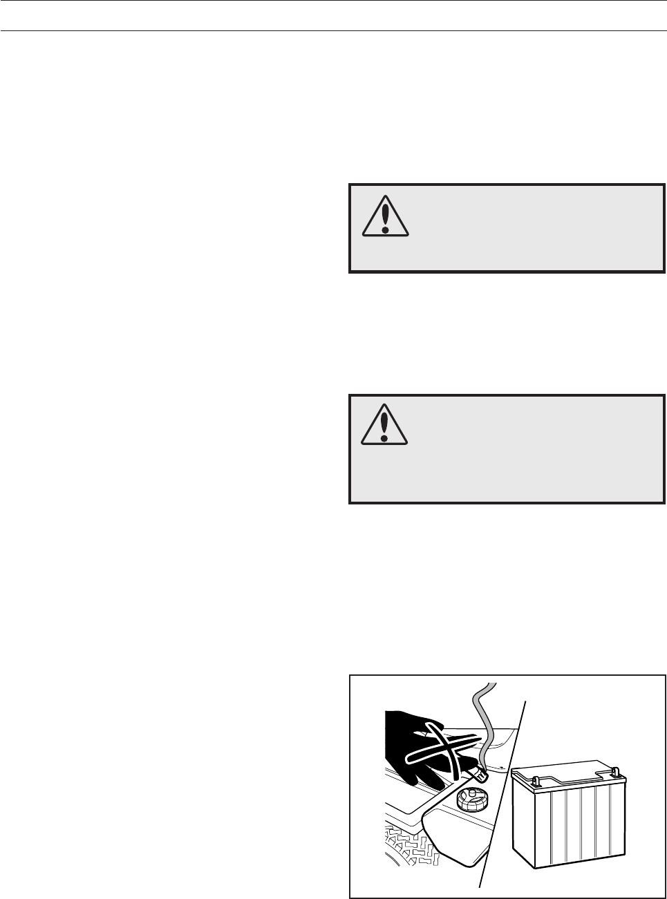
Batteries emit explosive gas. Sparks, flames
and cigarettes must absolutely not be
brought into the vicinity of the battery.
Check the level of the battery acid
Check that the level of the battery acid lies between
the markings. Top up the cells with
only
distilled
water.
6008-013
8009-461
8009-462
6. Insert the paper filter and check that it is correct
sealed to its seat. Tighten the paper filter wing
nut and install the precleaner over the paper
filter.
7. Fit the air filter cover and tighten its wing nut.
5. The paper filter may be carefully tapped on a
hard surface to remove dust. Do not try to wash
or blow it with compressed air.

English – 29
MAINTENANCE
Ignition system
The engine is equipped with an electronic ignition system. Only the spark plug requires maintenance.
For recommended spark plug, see chapter ”Technical data”.
IMPORTANT INFORMATION
Fitting the wrong spark plug type can damage the engine.
1. Remove the ignition cable shoe and clean around the spark plug.
2. Remove the spark plug with a 5/8" (16 mm) spark plug socket wrench.
3. Check the spark plug. Replace the spark plug if the electrodes are burned or if the insulation is cracked
or damaged. Clean the spark plug with a steel brush if it is to be reused.
4. Measure the electrode gap with a gapping tool. The gap should be 1,02 mm/0.040". Adjust as necessary
by bending the side electrode.
5. Reinsert the spark plug, turning by hand to avoid damaging the threads.
6. After the spark plug is seated, tighten it with 38-43 Nm (28-32 lbft).
7. Replace the ignition cable shoe.
IMPORTANT INFORMATION
Inadequately tightened spark plugs can cause overheating and damage the engine. Tightening the
spark plug too much can damage the threads in the cylinder head.
IMPORTANT INFORMATION
Do not turn over the engine if the spark plug or ignition cable has been removed.
30 – English
MAINTENANCE
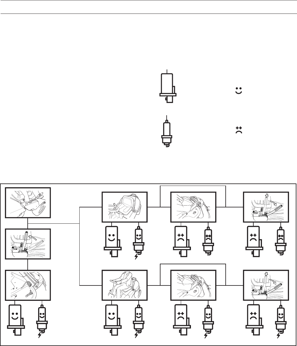
Checking the safety system
The Rider is equipped with a safety system that
prevents starting or driving under the following
conditions:
The engine should only be possible to start when
the cutting unit is in its raised position and the
hydrostat pedals are in the neutral position.
The driver does not need to be seated in the
driver’s seat.
Make daily inspections to ensure that the safety
system works by attempting to start the engine
when one of the conditions is not met. Change the
conditions and try again.
Check that the engine stops if you temporarily
move out off the driver’s seat while the cutting unit
is lowered or the hydrostat pedals are not in the
neutral position.
Start engine
Ignition system
Works
Does not work
English – 31
MAINTENANCE
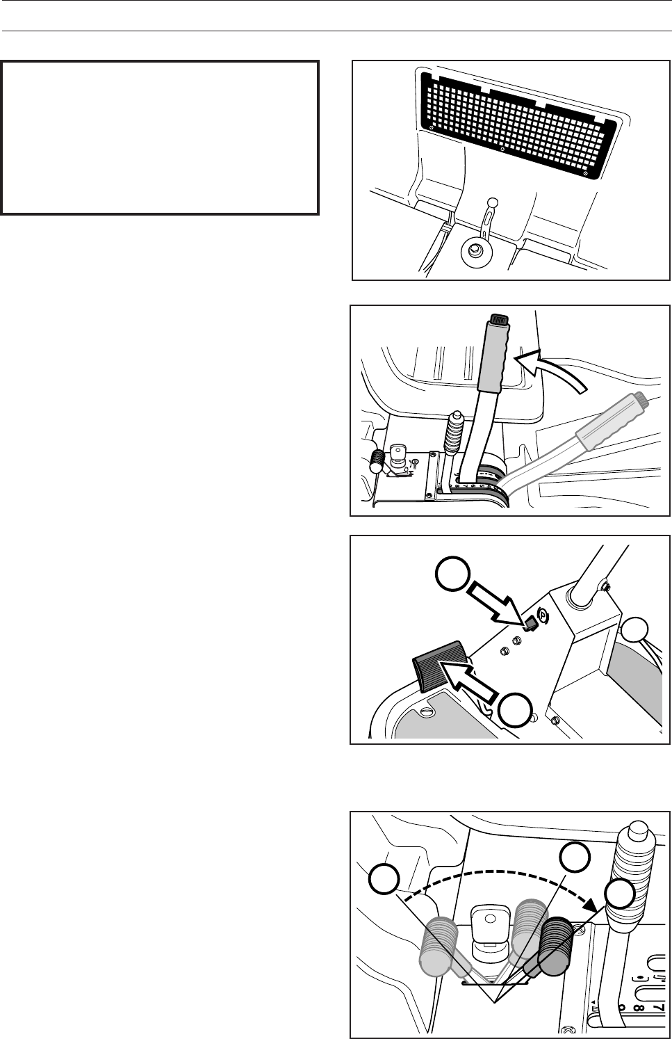
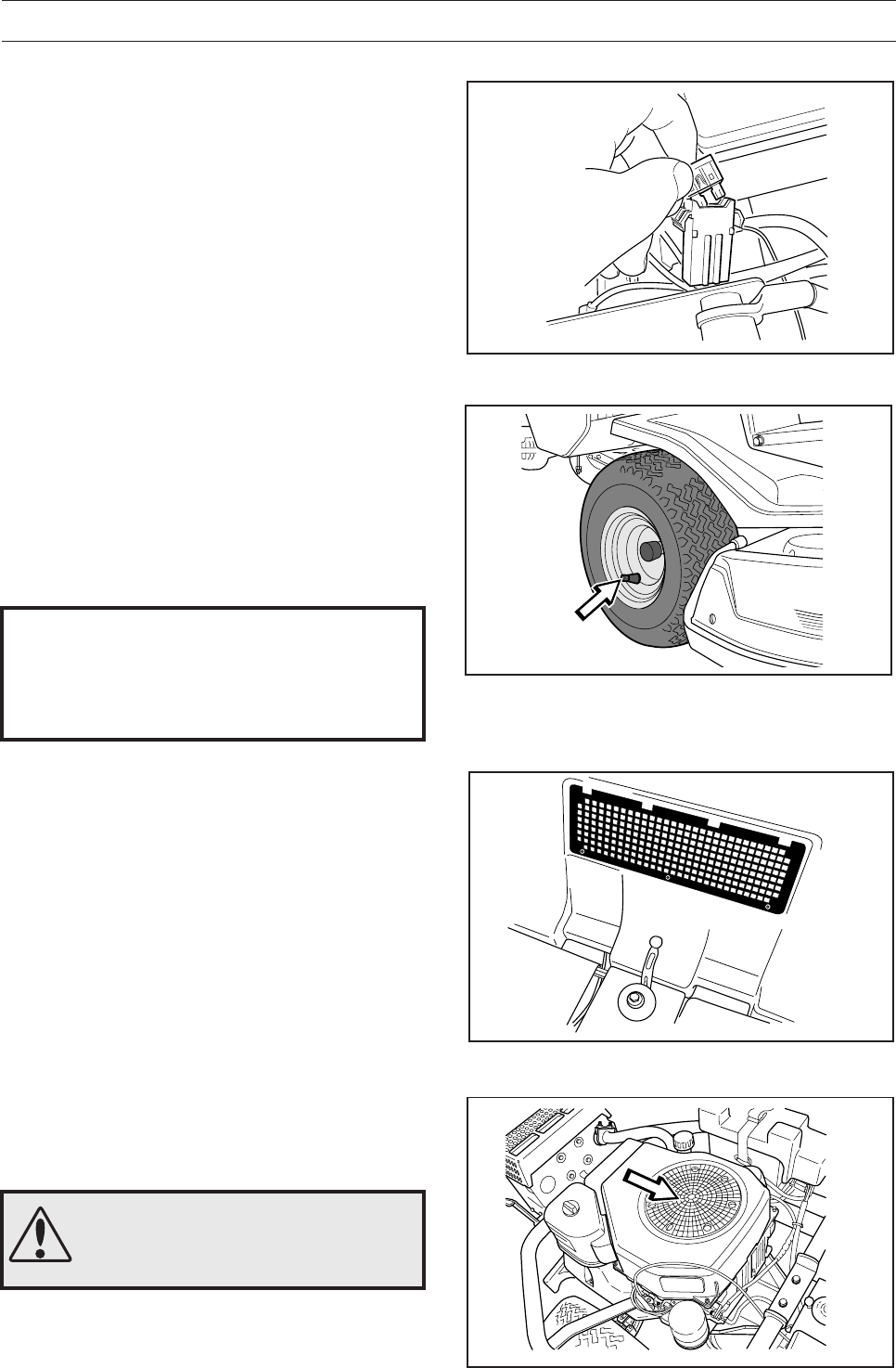
Check the engine’s cooling air intake
Clean the air intake grille in the engine cover
behind the driver’s seat.
Fold open the engine cover.
Check that the cooling intake is free from leaves,
grass and dirt.
Check the air duct, located on the inside of the
engine cover, ensure it is clean and does not rub
against the cooling air intake.
If the cooling intake is blocked this will interfere with
the cooling of the engine, which can damage the
engine.
Checking the tyre pressure
The tyre pressure should be 60 kPa (0.6 kp/cm2/8.5 PSI)
all round.
To improve driving the pressure on the rear tyres
can be reduced to 40 kPa (0.4 kp/cm2/5.6 PSI).
The maximum tyre pressure is 100 kPa
(1.0 kp/cm2/14 PSI).
IMPORTANT INFORMATION
Different tyre pressures on the front tyres
will result in the blades cutting the grass
at different heights.
Main fuse
The fuse is located in a loose holder under the
battery case cover, in front of the battery.
Type: Flat-blade mounting, 15 A.
Do not use any other type of fuse when replacing.
A blown fuse indicates that the mounting has burnt
off. Pull the fuse out of the holder when replacing.
The fuse is used to protect the electrical system. If
it blows again shortly after replacing this is due to a
short circuit, which must be rectified before the
machine is used again.
WARNING!
The cooling air intake rotates
when the engine is running. Mind
your fingers.
RIDER 850
RIDER 850
6008-030
8009-370
8009-431
Air intake grille
Cooling air intake
8009-470
32 – English
MAINTENANCE
1
2
3
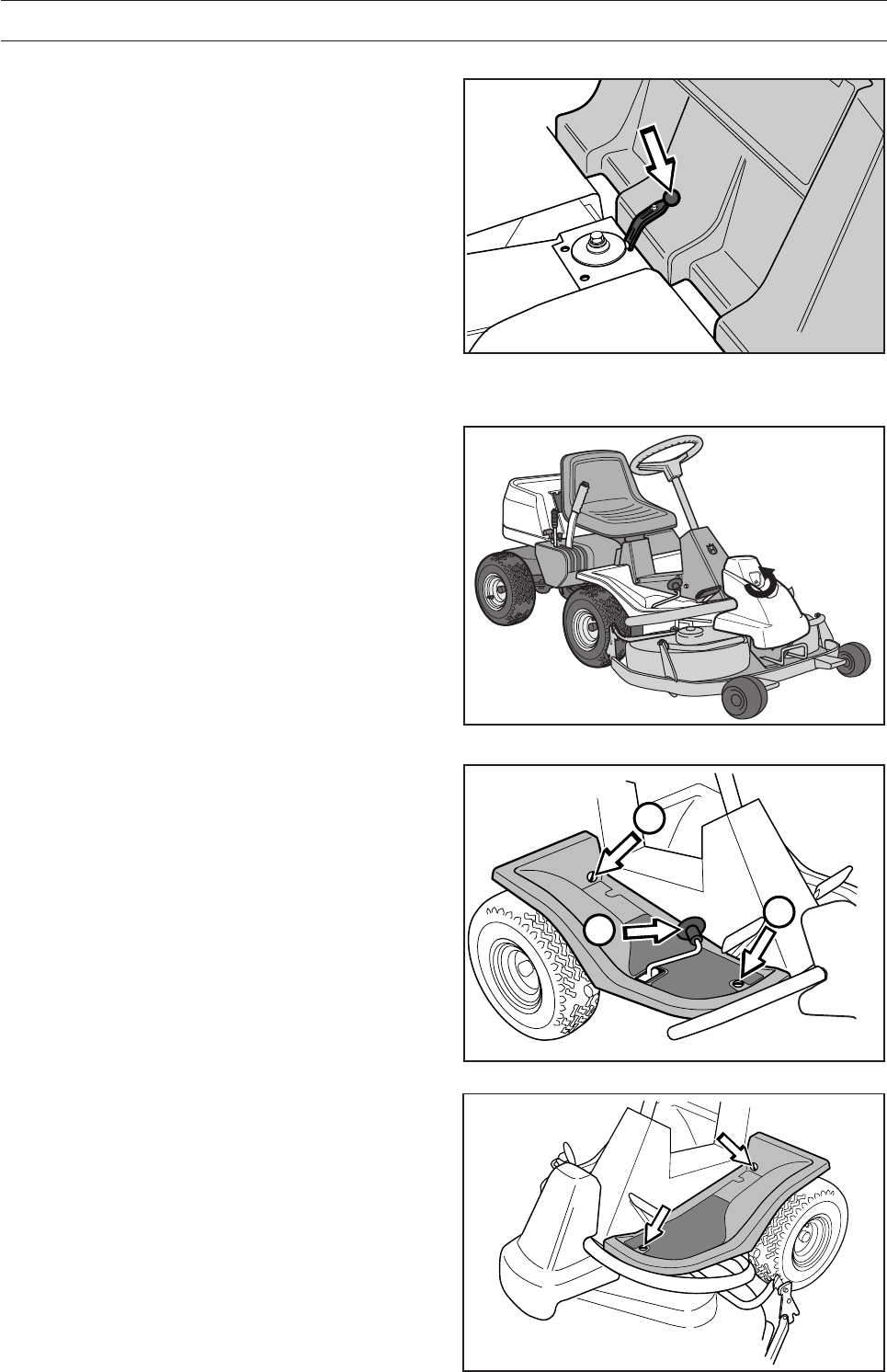
Fitting the cutting unit
1. Place the Rider on a flat surface and apply the
parking brake. Check that the lever for setting the
cutting height is in the lowest position.
Make sure the support wheels are fitted to the
cutting unit (1).
2. Grasp the handle at the front (BioClip 90) or hold
the frame of the cutting unit (2) and slide the unit
underneath the rider mower, making sure that
the tongue on the cutting unit (3) engages
correctly.
3. Insert the bolt and secure it with a locking pin.
4. Press down the frame and insert the pin. Fit the
drive belt around the drive wheels of the cutting
unit.
5. Hook up the height adjustment strut.
6. Fit the front cover.
7. Secure the collet’s spring, see ring in the
diagram below.
6017-159
6017-120
6017-160
WARNING!
Observe caution to avoid trapping
your hand.
8009-438
English – 33
MAINTENANCE
Checking and adjustment of the cutting
unit’s ground pressure
To achieve the best cutting results the cutting unit
should follow the underlying surface without pres-
sing too hard against it.
The pressure is adjusted with a screw on each side
of the machine.
1. Check the air pressure in the tyres 60 kPa
(0.6 kp/cm2/8.5 PSI).
2. Place the Rider on a flat surface.
3. Put the lifting lever in the mowing position.
4. Place a set of bathroom scales under the cutting
unit’s frame (front edge) so that it rests on the
scales. If necessary a block can be placed
between the frame and scales so that the
support wheels do not bear any weight.
5. Adjust the unit’s ground pressure by screwing in
or out the adjusting screws located behind the
front wheels on both sides.
The ground pressure should be between
12 and 15 kg (26.5-33 lb).
Checking the cutting unit’s parallelism
Check the parallelism of the cutting unit as follows:
1. Check the air pressure in the tyres 60 kPa
(0.6 kp/cm2/8.5 PSI).
2. Place the machine on a level surface.
3. Put the lifting lever in the mowing position.
4. Measure the distance between the ground and
the front and rear edges of the cutting unit hood.
The cutting unit should slope forwards slightly so
that the rear edge is 2-4 mm (1/8") higher than
the front edge.
6017-216
6008-019
6017-217
1
2
8
9
Installing BioClip 90
In order to install BioClip 90 the drive belt support
wheel must first be removed.
1. Release the tensioning wheel’s spring, see ring
in the diagram.
2. Remove the locking pin (1) that is located next to
the support wheel.
3. Screw off the nut and washer (2) under the
centre of the support wheel. Remove the screw
and support wheel.
4. Fit the cutting unit according to the instructions
above.
6017-142
34 – English
MAINTENANCE
WARNING!
Wear protective glasses when
dismantling the cutting unit. The
spring which tensions up the belt
can go off and cause personal
injury.
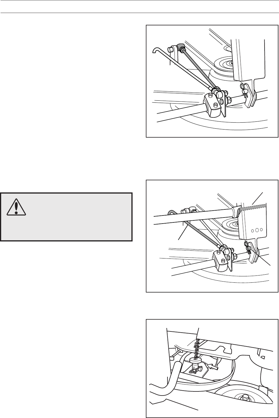
Adjusting the parallelism of the cutting
unit
1. Remove the front hood and the right-hand
fender, as described on page 21.
2. Undo the nuts on the lift strut.
3. Screw out (extend) the stay to raise the rear
edge of the cover.
Screw in (shorten) the stay to lower the rear
edge of the cover.
4. Tighten the nuts after adjustment.
5. On completion of the adjustment the unit’s
parallelism should be re-checked.
6. Fit the right-hand fender and the front hood.
Removing the cutting unit
1. Carry out points 1-9 to put the cutting unit in the
service position, see “Service position for the
cutting unit” on page 33.
2. Remove the bolt (3) and lift off the cutting unit.
Fitting of the cutting unit takes place in the reverse
order to removal. See page 29 for details of how to
fit the BioClip 90.
When assembling: Make sure that the unit’s “lug”
enters the loop correctly on the underside of the
machine.
2
3
1
6017-018
6017-021
8009-123
English – 35
MAINTENANCE
IMPORTANT INFORMATION
The blades on a BioClip unit should be
set at 90 degrees to each other. In all
other cases the blades can collide and
cause serious damage to the cutting unit.
Replacing the cutting unit belts
Belt replacement on BioClip 90
The BioClip 90 is driven by a toothed belt that
synchronises rotation of the blades. The belt is
located under the cover of the cutting unit.
When changing the belt on a BioClip 90 follow
steps 1-7 of the above procedure for version 2.
NOTE! BioClip 90 has just 1 belt.
Belt replacement on the Combi 103, 112 cutting
unit
On these cutting units with "collision-proof" blades,
the blades are driven by one V-belt. Do as follows to
change the V-belt:
1. Remove the cutting unit, see page 31.
2. Undo the bolt on the lift strut and the two screws
on the cover. Lift the cover off the cutting unit.
3. Loosen the spring that tensions the V-belt and
pry off the belt.
Simply reverse the procedure to fit the new belt.
6012-079
8009-287
6012-080
36 – English
MAINTENANCE
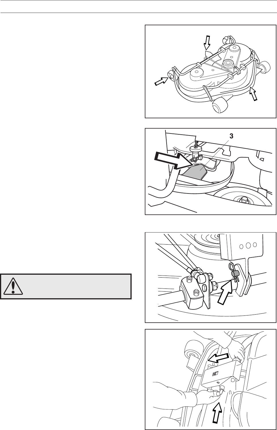
Service position for the cutting unit
The cutting head can be placed in the service
position to provide easy access for cleaning, repairs
and servicing. In service position, the cutting unit is
raised and locked in the vertical position.
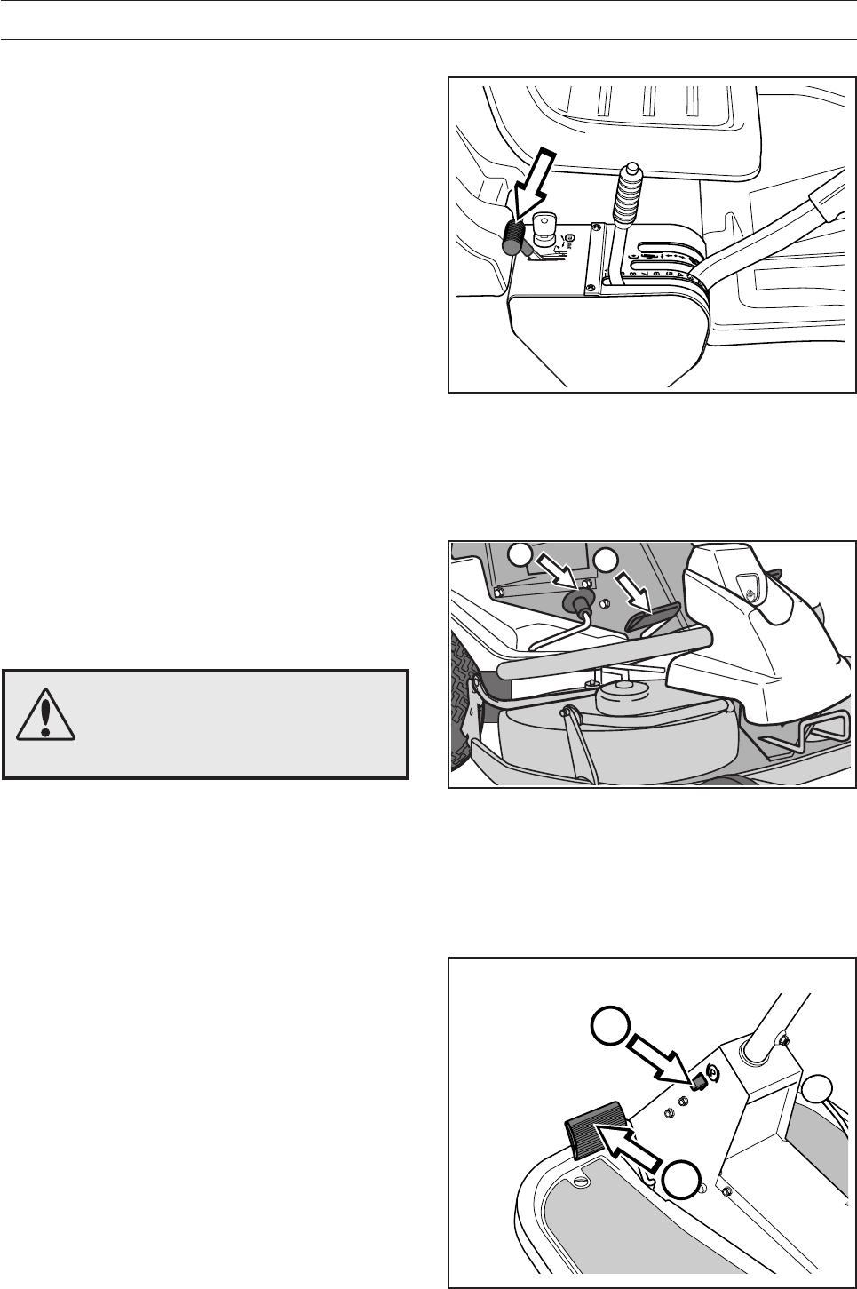
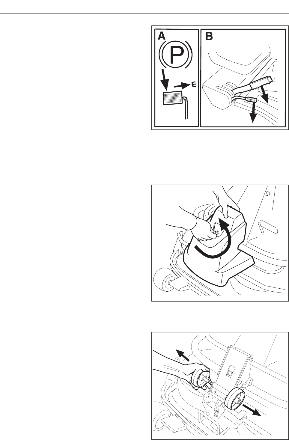
Placing in service position
1. Position the machine on flat ground. Apply the
parking brake (A). Adjust the cutting unit to the
lowest cutting height and lower the cutting unit
(B).
2. Remove the front hood by removing the pin.
(There are complete instructions on using the
service position inside the front hood).
3. Remove the two support wheels from under the
front hood.
8009-437
6017-219
6017-220
English – 37
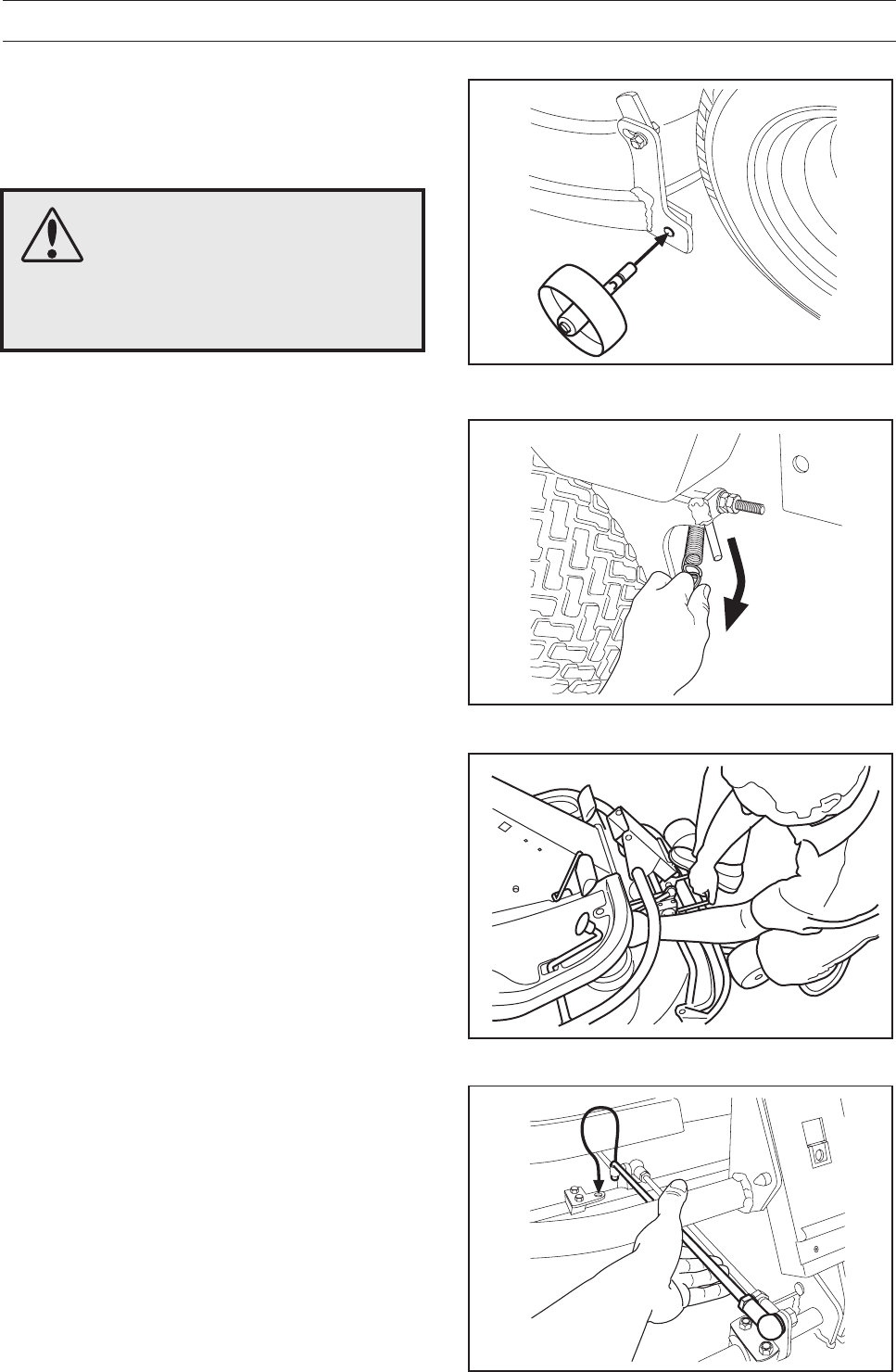
MAINTENANCE
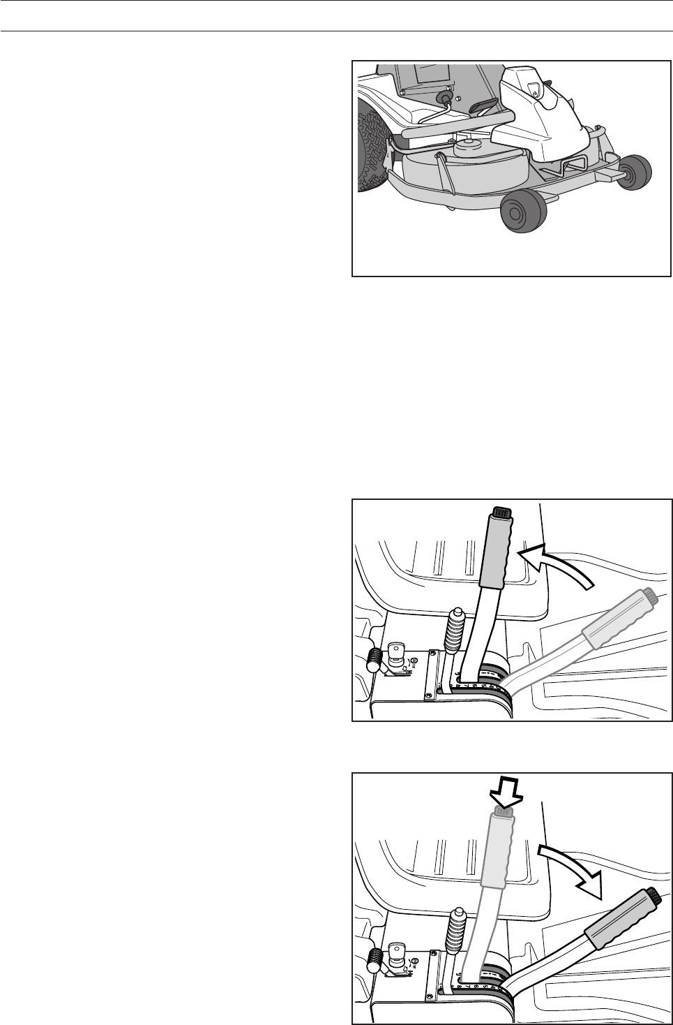
4. Fit the support wheels on either side of the rear
of the cutting unit.
5. Disengage the spring for the drive belt
tensioning wheel.
6. Place a foot on the front edge of the cutting unit
near the wheel and raise the front edge of the
unit to make it easier to remove the lift strut.
Engage the strut in the holder.
WARNING!
Wear protective glasses when
dismantling the cutting unit. The
spring which tensions up the belt
can go off and cause personal
injury.
6017-221
6017-222
8009-122
6017-223
38 – English
MAINTENANCE
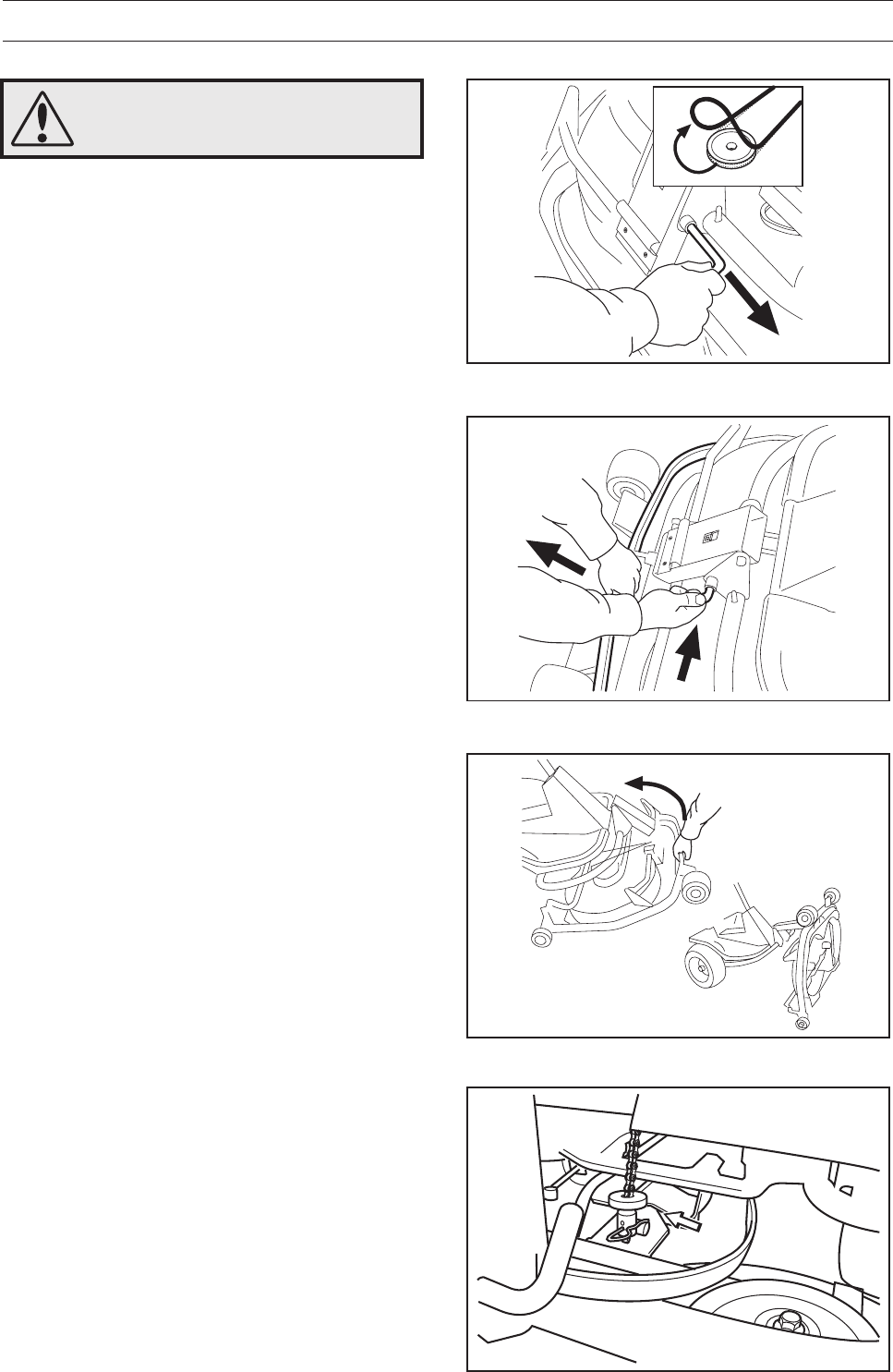
Restoring from service position
To leave the service position, reverse the
procedures set out in “Placing in the service
position”. Make sure that the cutting unit’s ”lug”
enters the loop correctly on the underside of the
machine, see diagram.
2
1
7. Lift off the drive belt (1). Then pull out the pin
(2).
8. Pull the frame forwards and refit the pin.
9. Grasp the front edge of the cutting unit, pull out
and raise into the service position.
If the cylindrical bolt, which is now holding the
cutting unit is removed, the cutting unit can be
lifted off.
6017-225
6017-226
6017-227
8009-123
WARNING!
Observe caution to avoid
trapping your hand.
English – 39
MAINTENANCE
Checking the blades
To achieve the best mowing results it is important
that the blades are undamaged and well-sharpened.
Check that the blades’ attachment screws are tight.
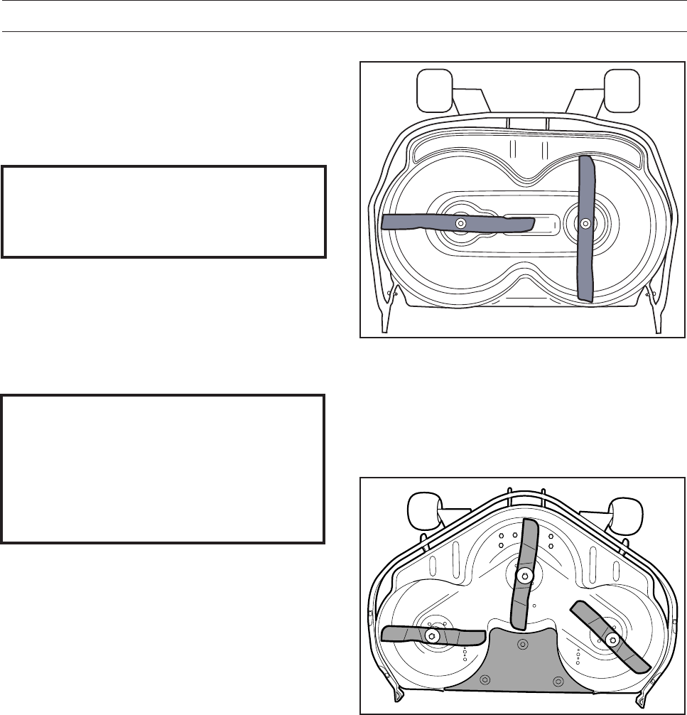
IMPORTANT INFORMATION
Replacing or sharpening the blades
should be conducted by an authorised
service workshop.
IMPORTANT INFORMATION
BioClip units 90 should always have the
blades in the relative position shown in the
diagrams with an angle of 90° between the
blades. Otherwise the blades can go
against each other and damage the unit.
The blades should be balanced after sharpening.
Damaged blades should be replaced when hitting
obstacles that result in a breakdown. Let the
servicing dealer judge whether the blade can be
repaired/ground or must be discarded.
8009-288
Combi 103/112
6017-023
BioClip 90
40 – English
MAINTENANCE
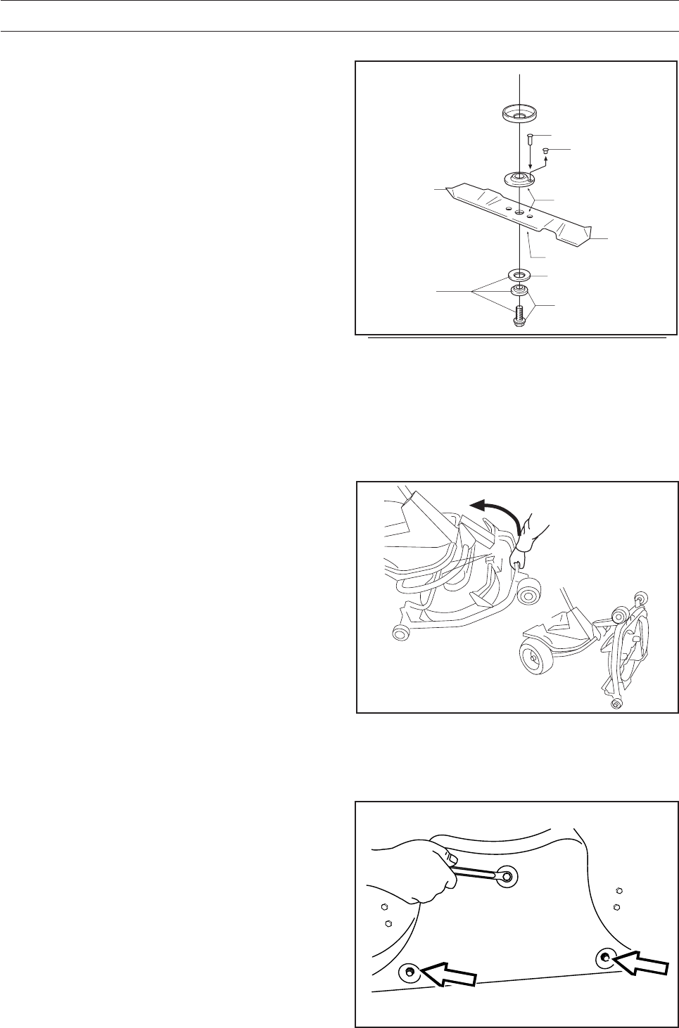
Replacing the break-pin (BioClip 90)
The blades are fitted with a break-pin to protect the
BioClip unit and its drive when colliding with
obstacles. A domed, spring friction washer is fitted
to each blade bolt. The washer must always be
replaced with a new washer if the blade bolt is
loosened. Otherwise the break-pin can break
causing the blades to collide.
Only use original spare parts. A set containing a
blade, break-pin and friction washer can be
purchased from your dealer.
1. Put the cutting unit in the service position, see
”Service position for the cutting unit\Placing in
the service position”.
2. Remove the blade (2A) by removing the blade
bolt with washer and friction washer (2B).
3. Remove the remains of the broken break-pin (3).
4. Make sure the contact surfaces (4) on the blade
and the blade mounting are metalic clean. Clean
if necessary.
5. Fit one new break-pin (5) in the blade mounting.
6. Fit the blade (6) and make sure it is fitted as
illustrated.
7. Fit a new friction washer (7) with the concave
face turned towards the blade.
8. Fit the blade bolt with washer (8). Tightening
torque 45-50 Nm (4,5-5 kpm/32-36 lbft).
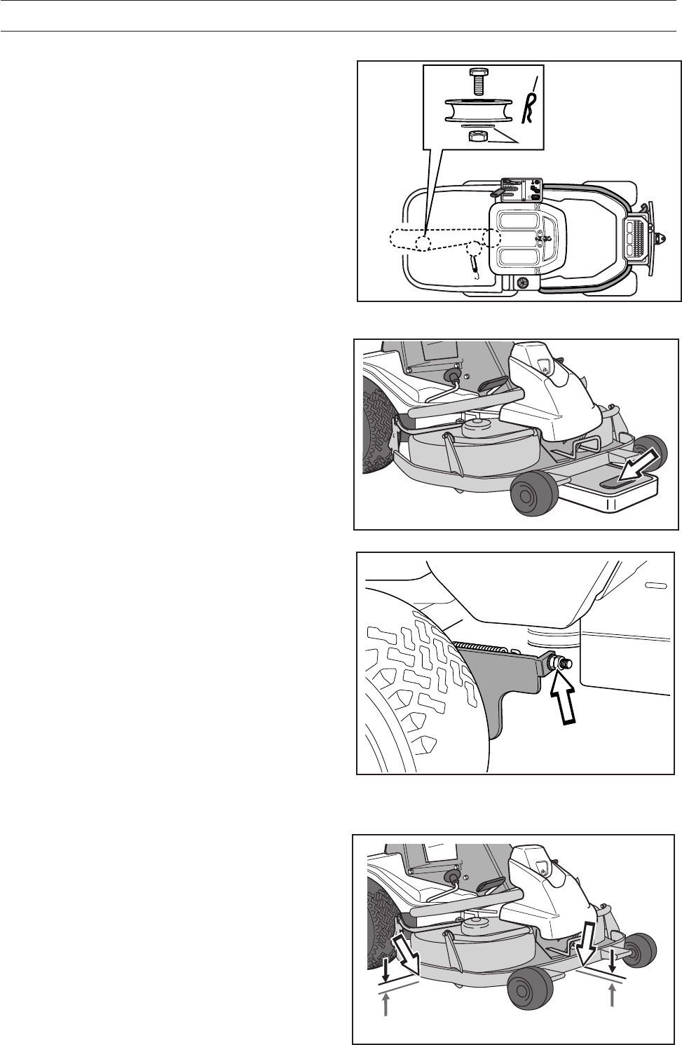
Removal of BioClip plug (Combi)
To change a Combi unit from BioClip function to
cutting unit with rear ejection, remove the BioClip
plug located under the unit with three screws.
1. Put the unit in the service position, see "Placing
in the service position".
2. Remove the three screws holding the BioClip
plug, and remove the plug.
3. Tip: Fit three full-thread screws M8x15 mm in
the screw holes to protect the threads.
4. Replace the unit in normal position.
Fit the BioClip plug in the reverse order.
2B
3
4
4
6
2A
7
8
5
8009-137
8009-289
6017-227
Removal of BioClip plug
Service position
English – 41
LUBRICATION
Changing the oil
The oil should be changed for the first time after 5
hours of running time. Thereafter it should be
changed every 50 hours of running time.
With heavy loads or high temperatures replace the
oil after every 25 hours.
WARNING!
Engine oil can be very hot if it is
drained off directly after the engine
is stopped. Therefore allow the
engine to cool down first.
IMPORTANT INFORMATION
Used engine oil is hazardous to health and
environment and must in accordance with
the law not be poured out on the ground
or in the nature, and must be handed in to
a workshop or other designated station for
treatment. Avoid skin contact, wash with
soap and water in the event of spillage.
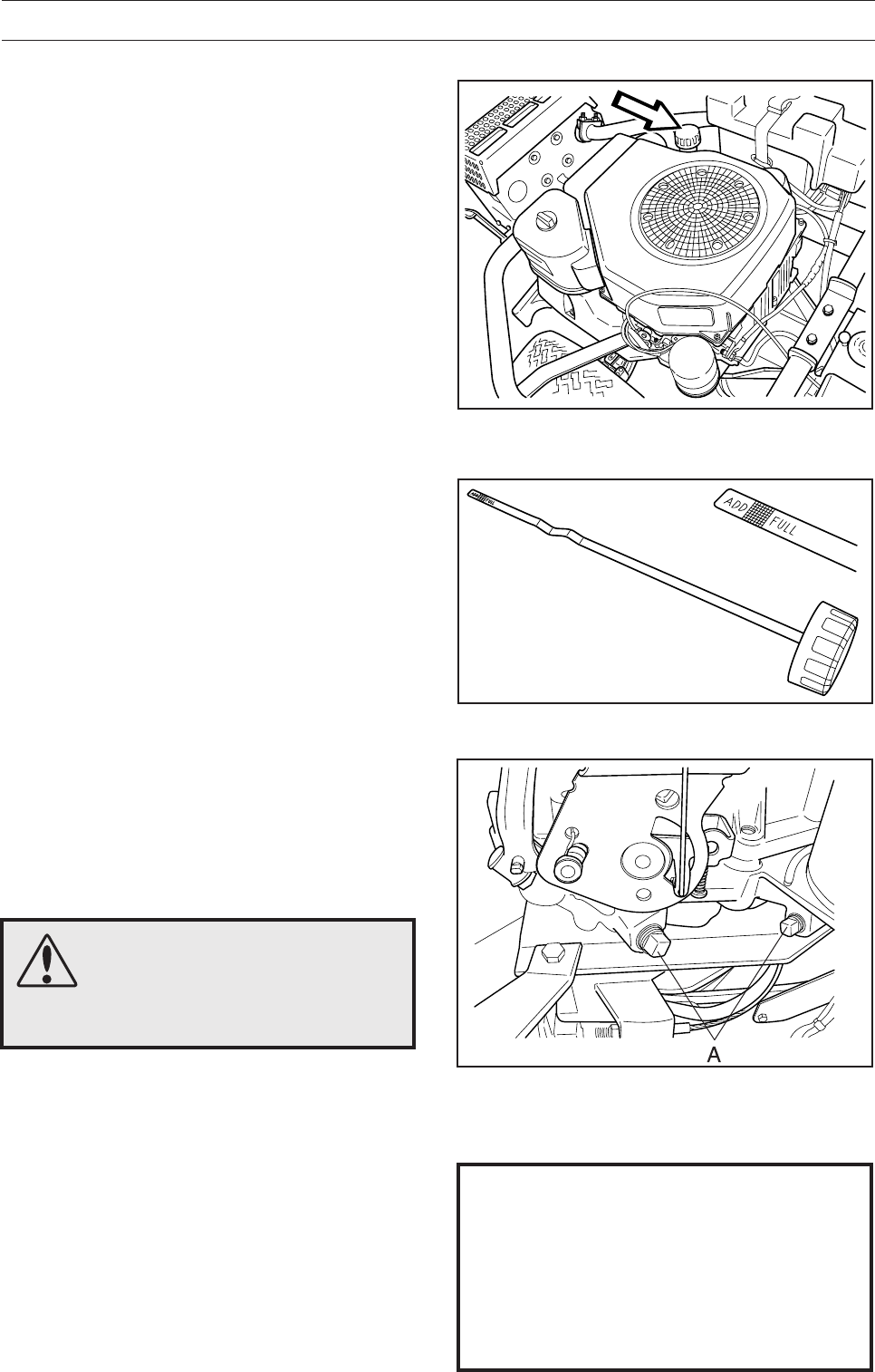
Check the engine’s oil level
Check the oil level in the engine when the Rider
stands horizontal with the engine switched off.
Fold open the engine cover.
Release the dip stick and pull out. Wipe off the oil
and insert again.
The dip stick must be fully screwed down.
Now release the dip stick again and pull out. Check
the oil level.
The oil level should be between the markings on
dip stick. If the level approaches the ADD mark, top
up with oil to the FULL mark.
The oil is filled in the same hole as for the dip stick.
Fill the oil slowly. Tighten the dipstick correctly
before starting the engine. Start and run the engine
at idling speed for approx. 30 seconds. Turn off the
engine. Wait 30 seconds and check oil level. If
necessary fill so that the oil comes up to the ”FULL”
mark on the dipstick.
First and foremost use synthetic engine oil class
SJ-CF 5W/30 or 10W/30 for all temperature ranges.
Mineral oil SAE30, class SF–CC can be used at
temperatures > +5°C (40°F).
Do not mix different types of oil.
1. Place a receptacle under the engine’s drain
plug, located on the left-hand side of the engine.
2. Remove the dip stick and drain plug (A).
3. Let the oil run out into the receptacle.
4. Fit the drain plug and tighten.
5. Fill up with oil to the FULL mark on the dip stick.
The oil is filled in the same hole for the dip stick.
See ”Checking the engine’s oil level” above for
filling instructions. The engine holds 1.9 litres
(1.8 USqt) of oil.
6. Run the engine warm and then check that there
is no leakage from the drain plug.
8009-471
8009-464
8009-465
42 – English
LUBRICATION
Lubricating the belt adjuster
The belt adjuster should be lubricated regularly
using good quality molybdenum disulphide
grease*.
1 nipple from the right-hand side under the engine’s
lower belt pulley, until grease is forced out.
With daily use lubrication should be conducted
twice a week.
General lubrication
All joints and bearings are lubricated on
manufacture with molybdenum sulphide grease.
Re-grease with same type of grease*. Lubricate the
steering and control wires with engine oil.
The machine should be lubricated regularly, and
twice a week when used daily.
* Grease from well-known brand names (petrol
companies, etc.) usually maintains a good quality.
The most important property is that the grease
provides good protection against corrosion.
Check the transmission’s oil level
1. Remove the transmission cover. Loosen both
screws (one on each side) and lift off the trans-
mission cover.
2. Check that there is oil in the transmission’s oil
tank. Fill if necessary with engine oil SAE 10W/
30 (class SF–CC).
6008-039H
6008-240H
6008-232
8009-466
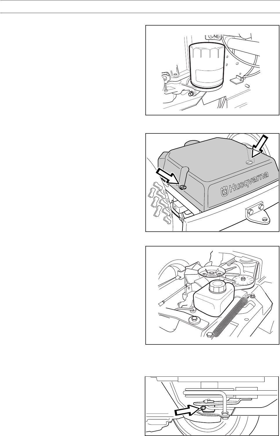
Change of oil filter
Replace oil filter every 200 operating hours. Drain
oil first using the plug on the filter base. Remove
the old filter using an oil filter tool. Lightly coat
rubber gasket with new oil, then install filter by
turning it to the right until hand tight. Tighten the
filter an additional 1/2 turn. Check that the drain
plug is reinstalled before starting the engine.
Start engine and check for leakage.

English – 43
Problem Procedure
Engine will not start. • Fuel tank empty.
• Spark Plug defective.
• Spark Plug connection defective.
• Dirt in carburettor or fuel pipe.
Starter does not pull round engine. • Battery flat.
• Bad contact between cable and battery terminal.
• Lift lever for cutting unit in wrong position.
• Main fuse blown. The fuse is placed in front of the
battery, under the battery cover.
• Ignition lock faulty.
• Gear shift/hydrostat pedal not in neutral.
• Hydrostat pedals not in the neutral position
Engine does not run smoothly. • Wrong gear, too high.
• Carburettor incorrectly set.
• Air filter clogged.
• Fuel tank vent blocked.
• Ignition setting defective.
• Dirt in fuel pipe.
• Choking or incorrectly adjusted throttle cable
Engine seems to have no power. • Air filter clogged.
• Spark Plug defective.
• Dirt in carburettor or fuel pipe.
• Carburettor incorrectly set.
• Choking or incorrectly adjusted throttle cable
Engine overheats. • Engine overloaded.
• Air intake or cooling flanges blocked.
• Fan damaged.
• Too little or no oil in engine.
• Ignition defective.
• Spark Plug defective.
Battery does not charge. • One or more cells faulty
• Bad contact between battery terminals and cables.
Machine vibrates. • Blades are loose.
• Engine is loose.
• Imbalance on one or more blades, resulting from
damage or inferior balancing after sharpening.
Uneven mowing. • Blades blunt.
• Cutting unit skew.
• Long or wet grass.
• Grass blockage under hood.
• Different tyre pressures on right and left sides.
• Over-speeding
• Drive belts slipping.
• The blade has a broken break-pin (BioClip)
TROUBLE SHOOTING SCHEDULE
44 – English
Winter storage
At the end of the season the machine should
immediately be put in order for storage, also if it is
going to stand idle for more than 30 days. Fuel
which is left to stand for long periods (30 days or
more) can leave tacky deposits which can block
the carburettor and interfere with the engine.
Fuel stabiliser is an acceptable alternative to avoid
tacky deposits during storage. If alkylate petrol
(Aspen) is used stabiliser is not necessary since
this fuel is stable. However, one should avoid
changing from standard to alkylate petrol since
sensitive rubber parts can harden. Add stabiliser to
the fuel in the tank or the storage container. Always
use the mixing ratios indicated by the manufacturer.
Run the engine for at least 10 minutes after adding
the stabiliser so that it will reach the carburettor. Do
not empty the fuel tank and carburettor if stabiliser
has been added.
STORAGE
WARNING!
Never place an engine with fuel in
the tank indoors or in poorly
ventilated areas where petrol
fumes can come into contact with
naked flames, sparks or pilot
flames in boilers, hot water
heaters, or drying cabinets, etc. It
is highly inflammable and
negligent usage can cause
severe person injury
and material damage. Drain off
the fuel in an approved container
outdoors and well clear of naked
flames. Never use petrol for
cleaning purposes. Use degrea-
sing agents and hot water
instead.
To put the machine in order for storage follow these
instructions:
1. Carefully clean the machine, especially under
the cutting unit. Touch-up paint damage to avoid
rust.
2. Inspect the machine for worn or damaged parts
and tighten loose screws and nuts.
3. Change the oil, and take care of the waste oil.
4. Empty the fuel tank. Start the engine and run it
until the carburettor is emptied of fuel.
5. Remove the spark plug and pour about a
tablespoon of engine oil in the cylinder. Turn
over the engine so that the oil is evenly
distributed and then refit the spark plug.
6. Grease all grease nipples, joints and axles.
7. Remove the battery. Clean it, charge it, and
store it in a cool place.
8. Store the machine in a clean and dry place and
cover it for extra protection.
Cover
There is a cover to protect your machine during
storage or transport. Contact your dealer for a
demonstration.
Service
When ordering spare parts, always state the
purchase year, model, type, and serial number.
Always use genuine parts.
Annual inspection or trimming by an authorised
service workshop is a good way of getting the best
out of your machine the next season.
6017-213

English – 45
Dimensions Rider 155
Length without cutting unit 2020 mm/6.61 ft
Width without cutting unit 880 mm/2.89 ft
Height 1060 mm/3.52 ft
Service weight 247-260 kg/543-572 lb including unit
Wheel base 855 mm/2.8 ft
Track Front 715 mm/2.34 ft, rear 625 mm/2.05 ft
Tyre size 16 x 6.50 x 8
Tyre pressure, front 60 kPa (0.6 kp/cm2/8.5 PSI)
& rear
Max. gradient 15°
Engine
Manufacture Kohler Engines model CV15
Power 11.4/15.5 kW/h.p.
Displacement 426 cm3/26 cuin
Fuel Min. 87 octane unleaded (Research min 90 octane)
(Gasohol < 10% etyl alcohol or MTBE < 15% by volume)
Tank volume 7 litres/7.4 USqt
Oil synthetic SAE 10W/30 (SAE 5W/30 below freezing point)
class SG or SH
Oil volume 1.9 litres/1.8 USqt
Start Electric starter
Noise emissions and cutting width
Measured noise level Bio 90: 99 dB(A),
Combi 103: 99 dB(A),
Combi 103: 100 dB(A)
Guaranteed noise level 100 dB(A)
Cutting width 900 - 1120 mm/35.5-44"
Electrical system
Type 12 V, negative earth
Battery 12 V. 24 Ah
Spark plug Champion QC12YC electrode gap = 1,02 mm/0.040"
Transmission
Manufacture Tuff Torq K46
Oil SAE 10W/30, class SF-CC
Cutting unit
Type 3-blade hood Combi 1030/1120 mm
2-blade hood BioClip 900 mm
Cutting width 900 mm/35.5"
1030 mm/40.5" (Combi) 1120 mm/44" (Combi)
Cutting heights 9 positions,
40-90 mm/1 9/16"-3 9/16", 45-95 mm/1 3/4"-3 3/4" (BioClip)
Blade diameter 350 mm/13 3/4" (Side), 410 mm/16 1/4" (BioClip103),
420 mm/16 1/2" (Combi 112), 440 mm 17 1/4" (BioClip 90)
TECHNICAL DATA

46 – English
We reserve the right to change technical specifications without prior notice.
Note that no legal claims are valid on the basis of information in this manual.
Use only genuine parts for repairs. The warranty is not valid if non genuine parts are used.
When this product is worn out or no longer used it should be returned to
the dealer or other appropriate body for recycling.
TECHNICAL DATA

English – 47
SERVICEJOURNAL
Work done
Pre-delivery service
1. Top up battery with acid and recharge for four hours.
2. Fit steering wheel, seat and any optional equipment.
3. Adjust cutting unit:
Adjust the lifting springs (the “weight” of the cutting unit should
be 12-15 kg/26.5-33 lbs). Only applies to BioClip.
Adjust cutting unit so that rear edge is about 2–4 mm/1/8"
higher than front edge.
Adjust cutting unit height setting so that cutting height limit is
5 mm/3/16" above the frame of the unit at the lowest cutting
height.
4. Check that engine has correct amount of oil.
5. Check that the right amount of oil is in the transmission.
6. Check and adjust tyre pressure (60 kPa/0.6 bar/8.5 PSI).
7. Connect battery.
8. Fill with fuel and start engine.
9. Check that machine does not move in neutral.
10. Check:
Forward drive.
Reverse drive.
Operation of blades.
Seat safety switch.
Lift lever safety switch.
Safety switch for the hydrostat pedals.
11. Check engine revs 2 900±100rpm.
12. Check the screws on the muffler. (10Nm)
13. Tell customer about:
Need and benefits of following the service schedule.
The need and advantages of leaving the machine for regular
service.
The effects of maintenance on the machine’s second hand
value.
Range of applications for BioClip.
14. Complete proof of sale, etc.
Pre-delivery service carried out.
No outstanding problems.
Certified:
After first 5 hours
1. Change engine oil.
Date, mileage, stamp, sign

48 – English
SERVICEJOURNAL
Work done Date, mileage, stamp, sign
´®z+H-[¶5-¨

English – 49
114 01 35-95
2004W48
´®z+H-[¶5-¨
