Husqvarna Pro 18 Awd Users Manual OM, Rider 15, 18, AWD, 2005 01
Pro 18 HUSO2005_EUenAPen__1150007-26
2015-01-24
: Husqvarna Husqvarna-Pro-18-Awd-Users-Manual-317576 husqvarna-pro-18-awd-users-manual-317576 husqvarna pdf
Open the PDF directly: View PDF ![]() .
.
Page Count: 84
Operator´s manual
Rider Pro 15 Pro 18
Pro 18 AWD
Please read these instructions carefully and make sure
you understand them before using the machine. English


English – 1
Operator’s manual for
Rider Pro 15, Pro 18 and Pro 18 AWD
CONTENTS
IMPORTANT INFORMATION
Read carefully through the Operator’s manual so that you know how to use and maintain the
Rider before you use it.
For service measures other than those described in this manual, please contact an authorised
dealer that provides parts and service.
Introduction ......................................................... 2
Driving and transport on public roads .............. 2
Towing .............................................................. 2
Use ................................................................... 2
Serial Number .................................................. 3
Explanation of symbols ...................................... 4
Safety instructions .............................................. 5
General Use ..................................................... 5
Driving on Slopes ............................................. 7
Children ............................................................ 8
Maintenance .................................................... 8
Transport ........................................................ 10
Presentation ...................................................... 11
Accelerator ..................................................... 11
Cutting Unit .................................................... 12
Placement of Controls .................................... 12
Throttle control ............................................... 13
Choke Lever ................................................... 13
Chronometer .................................................. 13
Lifting lever for the cutting unit ....................... 14
Cutting Height Adjustment Lever ................... 14
Parking Brake ................................................. 15
Seat ................................................................ 15
Refuelling ....................................................... 15
Lights and power outlet .................................. 15
Driving ................................................................ 16
Mowing Tips ................................................... 16
Clutch control ................................................. 17
Before Starting ............................................... 18
Starting the engine ......................................... 18
Driving the Rider ............................................ 20
Braking ........................................................... 20
Stopping the Engine ....................................... 21
Maintenance ...................................................... 22
Maintenance schedule ................................... 22
Dismantling the Rider covers ......................... 24
Checking and Adjusting the Steering Cables .. 25
Adjusting the parking brake ........................... 26
Checking and Adjusting the Throttle Cable .... 27
Checking and Adjusting the Choke Cable ...... 27
Inspecting the muffler ..................................... 27
Replacing the Fuel Filter ................................ 28
Checking the Fuel Pump’s Air Filter ............... 28
Air supply exhaust pipe .................................. 28
Checking the Transmission Air Intake ............ 28
Replacing the air filter Pro 15......................... 29
Replacing the air filter Pro 18......................... 30
Checking the engine’s cooling air intake. ....... 31
Cleaning the engine and muffler .................... 31
Checking the Battery Acid Level .................... 32
Ignition system ............................................... 32
Checking the safety system ........................... 33
Replacing the light bulbs ................................ 34
Fuses ............................................................. 35
Checking the Tyre Pressures ......................... 35
Replacing the rear drive belt
Pro 15 and Pro 18 .......................................... 36
Replacing the hydraulic pump’s
drive belt Pro 18 AWD.................................... 38
Replacing the front belt Pro 15, Pro 18 .......... 41
Replacing the front belt Pro 18 AWD ............. 41
Fitting the cutting unit ..................................... 43
Removing the Cutting Unit ............................. 44
Checking and Adjusting the Cutting Unit’s
Ground Pressure ............................................ 45
Cutting height ................................................. 45
Checking the parallelism of the cutting unit.... 46
Adjusting the parallelism of the cutting unit.... 46
Replacing the Cutting Unit’s Belts .................. 47
The Cutting Unit’s Service Position ................ 48
Placing in the Service Position ....................... 48
Inspecting the blades ..................................... 51
Removing the BioClip plug (Combi) ............... 52
Lubrication ......................................................... 53
Lubrication chart Pro 15 ................................. 53
Lubrication chart Pro 18 ................................. 54
Lubrication chart Pro 18 AWD ....................... 55
General .......................................................... 56
Lubricating the cables .................................... 56
Lubrication instructions according
to the schedule ............................................... 56
Trouble shooting chart ..................................... 64
Storage ............................................................... 65
Winter Storage ............................................... 65
Guard ............................................................. 65
Service ........................................................... 65
Wiring diagram .................................................. 66
Technical data ................................................... 69
EU Declaration of Conformity .......................... 71
Service Journal ................................................. 72

2 – English
Congratulations
Thank you for purchasing a Husqvarna Rider. Husqvarna Riders have been designed according to a unique
concept with a front mounted cutting unit and patented rear wheel steering. The Rider is built to give
maximum efficiency even in small and confined areas. Collected controls and a hydrostatic transmission
controlled by pedals also contribute to the machine’s performance.
This Operator’s Manual is a valuable document. Following the instructions (use, service, maintenance, etc.)
can considerably increase the life span of your machine and even increase its resale value.
When you sell your Rider, make sure to give the operator’s manual to the new owner.
The final chapter of this operator’s manual comprises a Service Journal. Ensure that service and repair
work is documented. A well-kept service journal reduces service costs for the season-based maintenance
and affects the machine’s resale value. Take the operator’s manual along when the Rider is left to the
workshop for service.
Driving and Transport on Public Roads
Check applicable road traffic regulations before driving and transport on public roads. You should always use
approved fasteners during transport and ensure that the machine is well secured.
Towing
Your machine is equipped with a hydrostatic transmission and, if necessary, you should only tow the
machine over short distances and at a low speed, otherwise there is a risk of damaging the transmission.
The power transmission must be disengaged when towing, see Clutch Control.
Use
This machine has been designed to mow grass on lawns and other open and level ground surfaces without
obstacles such as stones, tree stubs, etc., even when the machine is equipped with special accessories
provided by the manufacturer, for which the operating instructions are enclosed with the delivery. All other
types of use are incorrect. The manufacturer’s instructions with regard to driving, maintenance, and repair
must be followed precisely.
The machine may only be operated, maintained, and repaired by persons that are fully conversant with the
machine’s special characteristics and safety regulations.
Accident prevention regulations, other general safety regulations, occupational safety rules, and traffic
regulations must be observed.
Unauthorised modifications to the design of the machine may absolve the manufacturer from liability for any
resulting personal injury or property damage.
INTRODUCTION

English – 3
Engine Transmission
INTRODUCTION
Proper Service
Husqvarna’s products are sold all over the world and only by specialised retail traders offering complete
service. This ensures that you as a customer receive only the best support and service. Before the product
is delivered, the machine has, for example, been inspected and adjusted by your retailer, see the certificate
in the Service Journal in this operator’s manual.
When you need spare parts or support in questions about service, warranty issues, etc., please consult the
following professional:
This operator’s manual belongs to the
machine bearing serial number:
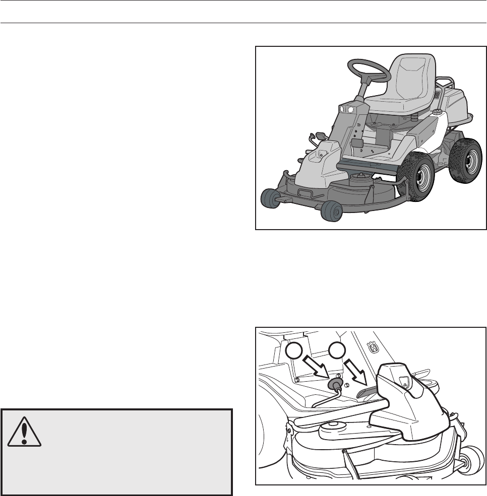
Serial Number
The serial number can be found on the printed plate attached to the front, left-hand side under the seat.
Stated on the plate, from the top, are:
• The machine’s type designation.
• The manufacturer’s type number.
• The machine’s serial number.
Please state the type designation and serial number when ordering spare parts.
The engine’s serial number is found on a barcode sticker. This is placed on the left side of the crankcase, in
front of the starter. The sticker states:
• The engine’s serial number (E/NO).
• Code.
Please state these when ordering spare parts.
The transmission’s serial number is stated on the barcode decal located on the front of the housing on the
left-hand drive axle:
• The type designation is stated above the barcode and starts with the letter K.
• The serial number is stated above the barcode and has the prefix s/n.
• The manufacturer’s type number is stated under the barcode and has the prefix p/n.
Please state the type designation and serial number when ordering spare parts.
4 – English
N
Never use the Rider if persons, especially
children or pets, are in the immediate vicinity. Never carry passengers on
the Rider or on its tools
Accelerator pedal forward
Neutral position
Accelerator pedal reversing
Starting instructions
Read the operator’s manual
Checking the engine oil level
Check the oil level in the hydrostat
Lift up the cutting unit
Hydrostat pedals in the neutral
position
Apply the parking brake.
Use the choke if the engine is cold.
Starting the engine
Disengage the parking brake before
driving
Drive very slowly
without the cutting
unit
Do not insert your hands or
feet under the cover when
the engine is running
Switch off the engine and remove
the ignition cable before carrying
out repairs or maintenance
CE conformity marking
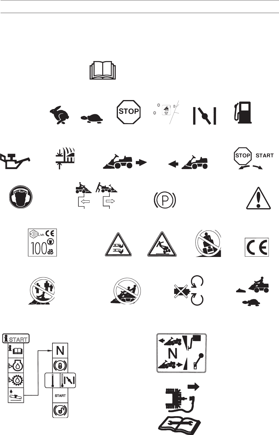
KEY TO SYMBOLS
These symbols can be found on the Rider and in the operator’s manual.
Study them carefully so you understand their significance.
Read the operator’s manual.
Neutral Fast Slow Engine off Tyre
pressures
Choke Fuel
Oil level Cutting height Reversing Forward Ignition
Use hearing
protection
Hydrostatic free
wheeling
Parking brake Warning
WARNING!
Rotating blades
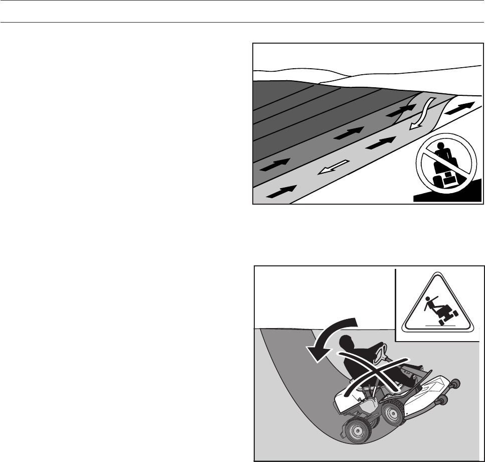
WARNING! Risk of the
Rider overturning
Never drive directly
across a slope
Noise emission to surroundings in accordance
with the directive of the European Community. The
machine’s emission is indicated in the TECHNI-
CAL DATA chapter and on the decal.
English – 5
8010-047
6003-002
8010-052
Safety Instructions
These instructions are for your safety. Read them carefully.
General Use
•Read all the instructions in this operator’s
manual and on the machine before you start it.
Ensure you understand them and then observe
them.
•Learn how to use the machine and its controls
safely and learn to how to stop quickly. Also
learn to recognise the safety decals.
•Only allow the machine to be used by adults
who are familiar with its use.
•Make sure nobody else is in the vicinity of the
machine when you start the engine, engage the
drive or drive off.
•Make sure animals and people maintain a safe
distance from the machine.
•Stop the machine if any one enters the working
area.
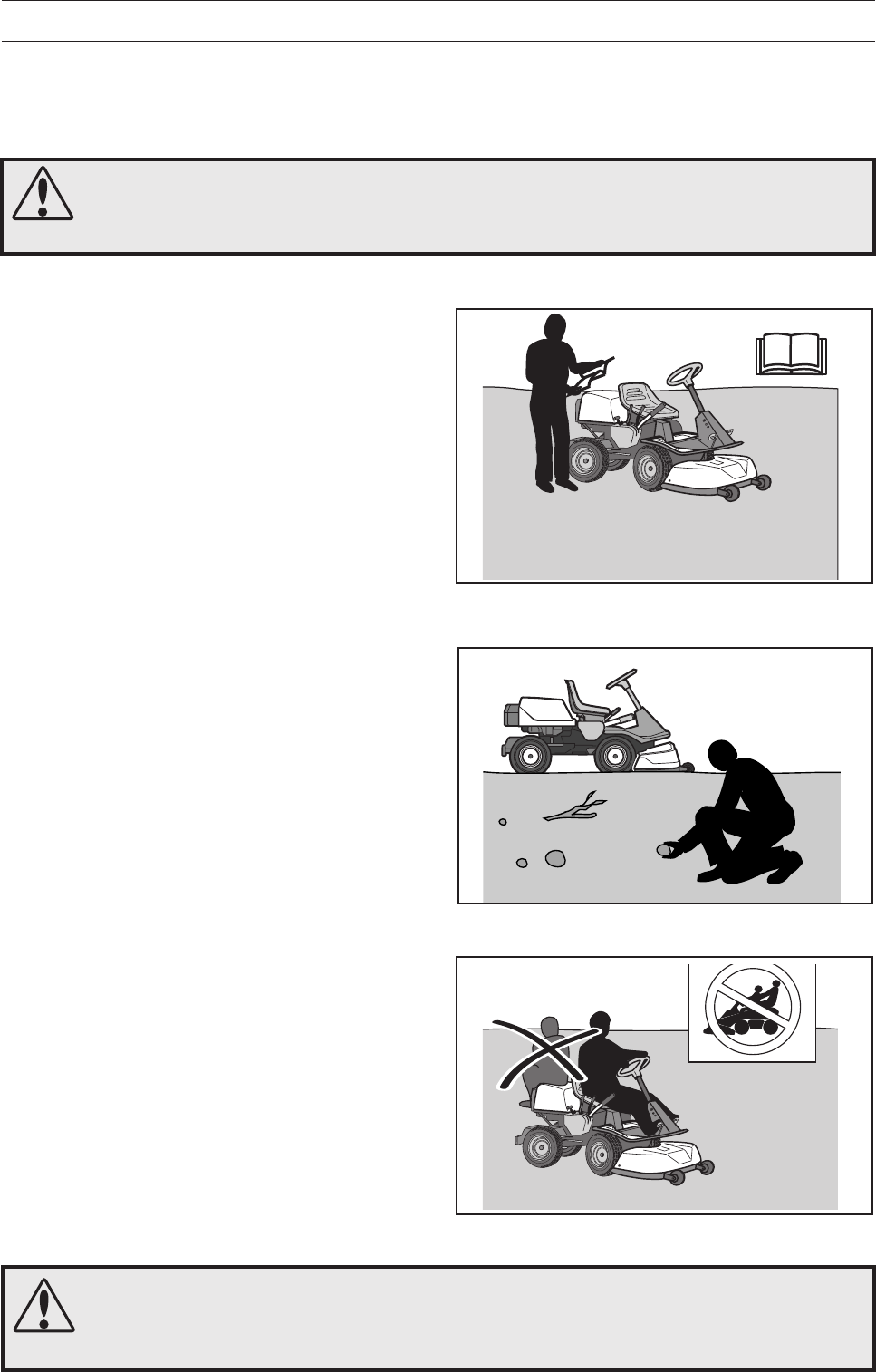
•Clear the area of objects such as stones, toys,
wires, etc. that may become caught in blades
and be thrown out.
•Look out for the ejector and do not direct it
towards anyone.
•Stop the engine and prevent it from starting
before you clean the cutting unit.
•Remember the operator is responsibility for
danger or accidents.
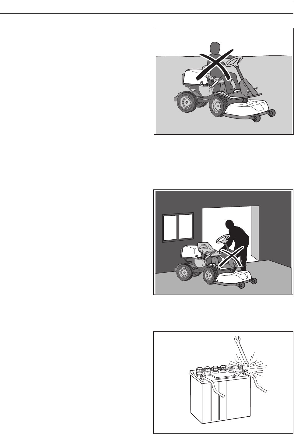
•Never carry passengers. The machine is only
intended to be used by one person.
•Always look downwards and backwards before
and while reversing. Keep watch for both large
and small obstacles.
•Slow before cornering.
•Switch off the blades when you are not mowing.
SAFETY INSTRUCTIONS
Never take passengers
WARNING!
This machine can sever hands and feet as well as throw objects.
Failure to observe the safety instructions can result in serious injuries.
Read the operator’s manual before starting the machine
Clear the area of objects before mowing
WARNING!
The inserted symbol means that important safety instructions need to be observed.
It applies to your safety.
6 – English
8011-292
6003-006
•Take care when rounding a fixed object, so that
the blades do not hit it. Never run the machine
over foreign objects.
•Only use the machine in daylight or in other well-
lit conditions. Keep the machine at a safe
distance from holes or other irregularities in the
ground. Pay attention to other possible risks.
•Never use the machine if you are tired, if you
have consumed alcohol, or if you are taking
other drugs or medication that can affect your
vision, judgment or co-ordination.
•Keep an eye on the traffic when working close to
a road or when crossing it.
•Never leave the machine unsupervised with the
engine running. Always stop the blades, apply
the parking brake, stop the engine and remove
the keys before leaving the machine.
•Never allow children or other persons not trained
in the use of the machine to use or service it.
Local laws may regulate the age of the user.
SAFETY INSTRUCTIONS
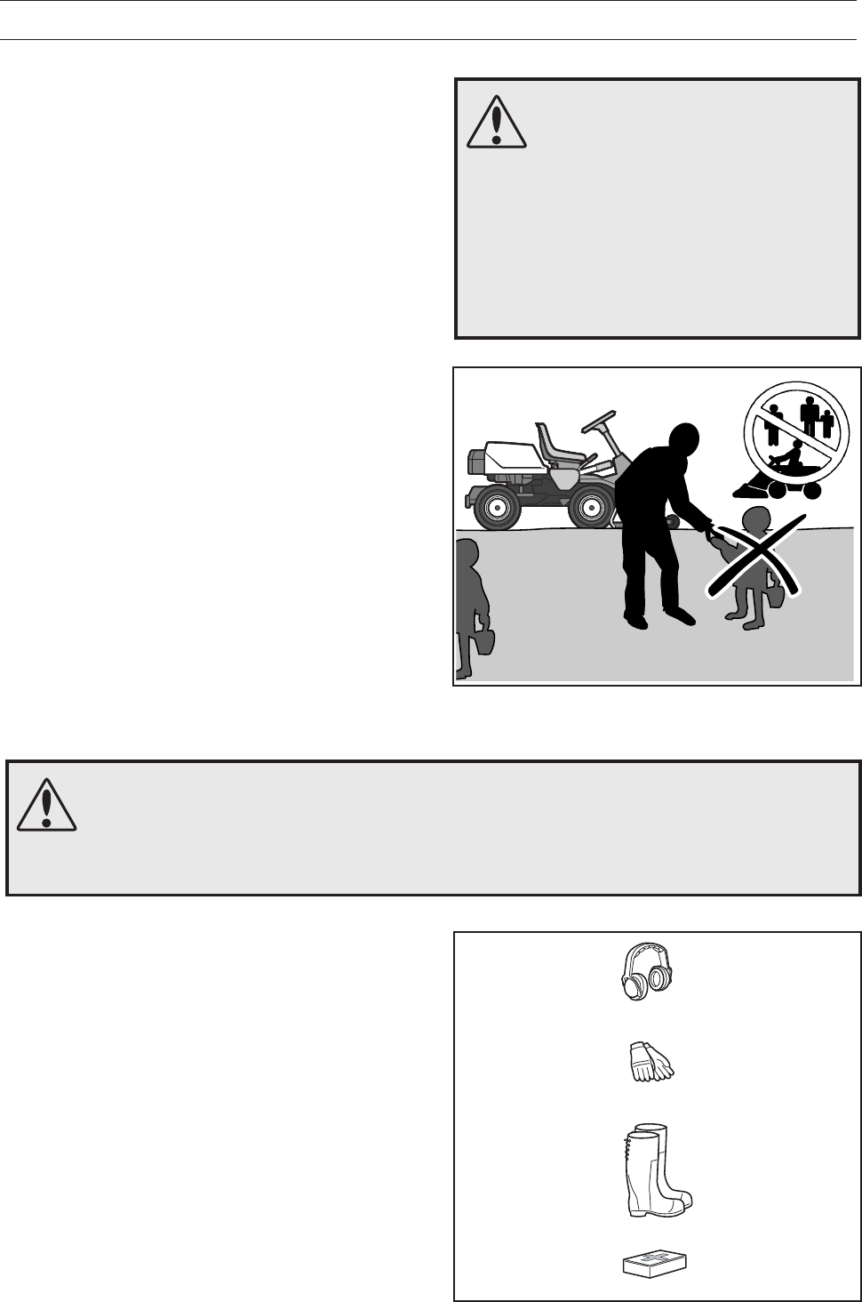
•Use hearing protection to minimise the risk of
hearing impairment.
•Wear approved protective glasses or full-face
visor during assembly and when operating.
•Never wear loose fitting clothes that can catch in
moving parts.
•Never use the machine when barefoot. Always
wear protective shoes or protective boots,
preferably with steel toes.
•Make sure that you have first aid equipment
close at hand when using the machine.
Keep children away from the work area
Personal protective equipment
WARNING!
You must use approved personal protective equipment whenever you use the
machine. Personal protective equipment cannot eliminate the risk of injury but it will
reduce the degree of injury if an accident does happen. Ask your dealer for help in
choosing the right equipment.
WARNING!
Engine exhaust, some of its
constituents and certain vehicle
components contain or emit
chemicals considered to cause
cancer, birth defects or other
reproductive impairment. The
engine emits carbon monoxide,
which is a colourless, poisonous
gas. Do not use the machine in
enclosed spaces.
English – 7
8010-054
6003-004
Be extra cautious when driving on slopes
Driving on Slopes
Driving on slopes is one of the operations where
the risk of the driver losing control of the machine or
of it overturning is the greatest; this can result in
serious injury or death. All slopes demand extra
care. If you cannot reverse up a slope or if you feel
unsure, do not mow it.
Proceed as follows:
•Remove obstacles such as stones, branches,
etc.
•Mow upwards and downwards, not sideways.
•Do not use the machine on ground that slopes
more than 15°.
•Avoid starting or stopping on a slope. If the tyres
start to slip, stop the blades and drive slowly
down the slope.
•Always drive smoothly and slowly on slopes.
•Do not make any sudden changes in speed or
direction.
•Avoid unnecessary turns on slopes, if
necessary, turn slowly and gradually downwards
if possible.
•Watch out for and avoid driving over furrows,
holes and bumps. It is easier for the machine to
overturn on uneven ground. Tall grass can hide
obstacles.
•Drive slowly. Do not turn the wheel sharply. The
machine engine-brakes better in low gear.
•Take extra care if any attachments are fitted that
can change the stability of the machine.
•Do not mow too close to edges, ditches or
banks. The machine can suddenly overturn if
one wheel comes over the edge of a steep slope
or a ditch, or if an edge gives way.
•Do not mow wet grass. It is slippery, and tyres
can lose their grip so that the machine skids.
•Do not try to stabilize the machine by putting
your foot on the ground.
•When cleaning under the machine, it may never
be driven near verges or ditches.
•Follow the manufacturer’s recommendations
regarding wheel weights or counterbalance
weights to increase stability.
SAFETY INSTRUCTIONS
Mow upwards and downwards on slopes, not sideways.
8 – English
8010-058
8009-728
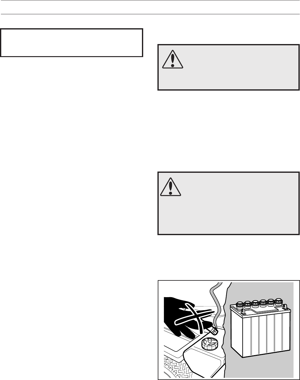
Risk of sparking
Children
•Serious accidents may occur if you fail to be on
your guard for children in the vicinity of the
machine. Children are often attracted to the
machine and mowing. Never assume that
children will stay put where you last saw them.
•Keep children away from the area to be mowed
and under close supervision by another adult.
•Keep an eye out and shut off the machine if
children enter the work area.
•Before and during reversing procedures, look
behind you and down for small children.
•Never allow children to ride along. They can fall
off and seriously injure themselves or be in the
way for safe manoeuvring of the machine.
•Never allow children to operate the machine.
•Be particularly careful near corners, bushes,
trees or other objects that block your view.
SAFETY INSTRUCTIONS
Never fill the fuel tank indoors
Maintenance
•Stopping the engine. Prevent the engine from
starting by removing the spark plug cables from
the spark plugs or by removing the ignition key
before making any adjustments or performing
maintenance.
•Never fill the fuel tank indoors.
•Petrol and petrol fumes are poisonous and
extremely flammable. Be especially careful when
handling petrol, as carelessness can result in
personal injury or fire.
•Only store fuel in containers approved for the
purpose.
•Never remove the fuel cap and fill the petrol tank
while the engine is running.
•Allow the engine to cool before refuelling. Do not
smoke. Do not fill petrol in the vicinity of sparks
or naked flames.
• Handle oil, oil filters, fuel and the battery
carefully, of environmental considerations.
Follow the local recycling requirements.
• Electrical shocks can cause injuries. Do not
touch cables when the engine is running. Do not
test the ignition system with your fingers.
• Sparking can occur when working with the
battery and the thick cables in the starter motor
circuit.
This can cause the battery to explode, fire or
eye injuries.
Sparking in the circuit can not occur once the
battery’s power connection cable (usually the
black negative cable) has been disconnected.
8010-057
Never allow children to operate the machine
English – 9
6003-009
- Wearing protective glasses.
- Make sure that the fuel cap is fitted and that no
flammable liquids are stored in an open container.
- Do not work on the starter motor circuit in the
vicinity of spilt fuel.
- Disconnect the battery’s power connection cable
(usually the black negative cable) first and
connect it last.
- Exercise care with tools so that short circuiting
does not occur.
- Do not short circuit across the starter relay’s
connections to run the starter motor.
•If leaks arise in the fuel system, the engine must
not be started until the problem has been resolved.
•Store the machine and fuel in such a way that
there is no risk that leaking fuel or fumes can
cause any damage.
•Check the fuel level before each use and leave
space for the fuel to expand, because the heat
from the engine and the sun may otherwise
cause the fuel to expand and overflow.
•Avoid overfilling. If you spill petrol on the
machine, wipe up the spill and wait until it has
evaporated before starting the engine. If you spill
petrol on your clothing, change your clothing.
•Allow the machine to cool before performing and
actions in the engine compartment.
•Be especially careful when handling battery
acid. Acid on the skin can cause serious
corrosive injuries. In the event of spillage on the
skin wash immediately with water.
•Acid in the eyes can cause blindness, contact a
doctor immediately.
•Take care with battery maintenance. Explosive
gases form in the battery. Never perform
maintenance on the battery while smoking or in
the vicinity of open flames or sparks. This can
cause the battery to explode and cause serious
injuries.
•Make sure all nuts and bolts are tightened
correctly and that the equipment is in good
condition.
•Do not modify safety equipment. Check regularly
to be sure it works properly. The machine must
not be driven if protective plates, protective
covers, safety switches or other protective
devices are not fitted or are defective.
SAFETY INSTRUCTIONS
Do not smoke when carrying out maintenance
WARNING!
The engine and the exhaust
system become very hot during
operation.
Risk of burn injuries if touched.
WARNING!
The battery contains lead and lead
pollutants, chemicals that are
considered to cause cancer,
birth defects or other reproductive
impairment. Wash you hands after
touching the battery.
IMPORTANT INFORMATION
Avoid sparking and its consequences by:
10 – English
8009-467
8010-061
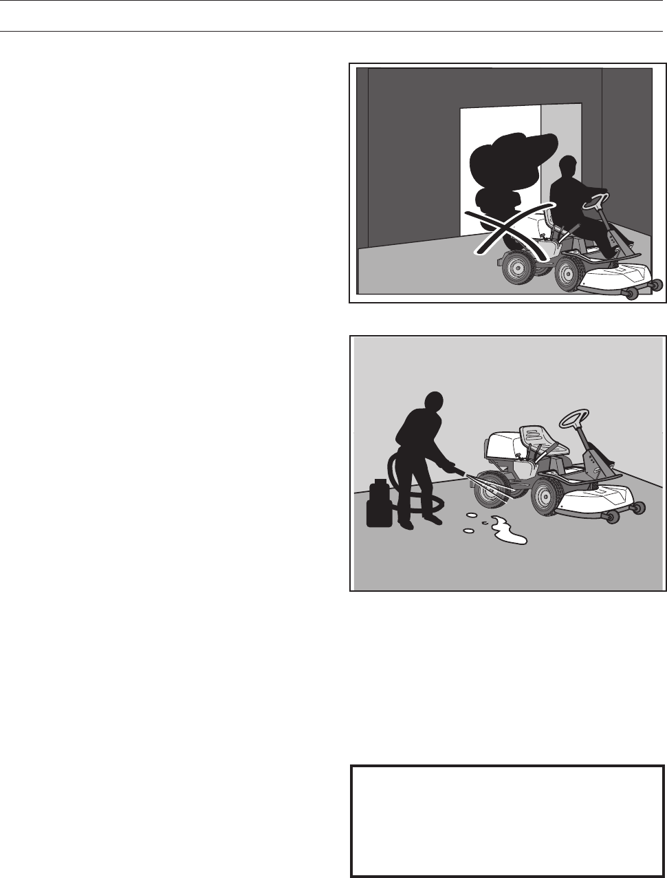
Never drive the machine in an enclosed space
Regularly clean grass, leaves and other debris from the
machine
SAFETY INSTRUCTIONS
•Do not change the setting of governors and
avoid running the engine at excessively high
revs. If you run too fast, you risk damaging the
machine components.
• Observe the risk of injury caused by moving or
hot parts if the engine is started with the engine
cover open or protective cowlings removed.
•Never use the machine indoors or in spaces
lacking proper ventilation. Exhaust fumes
contain carbon monoxide, an odourless,
poisonous and highly dangerous gas.
•Stop and inspect the equipment if you run over
or into anything. If necessary, make repairs
before starting.
•Never make adjustments with the engine
running.
•The machine is tested and approved only with
the equipment originally provided or
recommended by the manufacturer.
•The blades are sharp and can cause cuts. Wrap
the blades or wear protective gloves when
handling them.
•Check regularly that the parking brake works.
Adjust and maintain as required.
•The mulching unit should only be used where
better quality mowing is required and in known
areas.
•Reduce the risk of fire by removing grass, leaves
and other debris that may have fastened on the
machine. Allow the machine to cool before
putting it in storage.
Transport
•The machine is heavy and can cause serious
crush injuries. Be especially careful when it is
loaded in or out of a car or on and off of a trailer.
•Use an approved trailer to transport the
machine.
Activate the parking brake and secure the
machine using approved fasteners, such as
straps, chains or ropes when transporting.
•Check and observe local road traffic regulations
before transporting or driving the machine on
roads.
IMPORTANT INFORMATION
The parking brake is not sufficient to lock
the machine during transport. Ensure you
secure the machine firmly to the trans-
porting vehicle.
English – 11
8009-482
Presentation
Congratulations on your choice of an exceptionally
high quality product. This operator’s manual
describes Rider Pro 15, Pro 18 and Pro 18 AWD.
The machines are equipped with a four-stroke V-
Twin engine from Kawasaki. The figures denote the
amount of horse power.
The power transmission from the engine is handled
by a hydrostatic gearbox, which allows variable
variation of the speed by using the pedals.
One pedal to drive forwards and one pedal to reverse.
Pro 15 is the smallest professional machine in the
Rider series.
Pro 18 is equipped with power steering.
Pro 18 AWD is equipped with power steering and
all wheel drive.
PRESENTATION
21
6017-229
Accelerator
The speed of the machine is variably controlled
using two pedals. Pedal (1) is used to travel
forwards and pedal (2) to reverse.
WARNING!
Make sure that no branches can
interfere with the pedals when
mowing under bushes.
Risk for unintentional
manoeuvring.
12 – English
6017-230
Cutting Unit
The machines can be equipped with numerous
attachments.
The BioClip unit finely chops the grass several
times before returning it to the lawn as fertiliser.
The Combi unit functions as a BioClip unit when a
BioClip plug is fitted, but can be reset to rear
ejection by removing the BioClip plug.
See ”Maintenance \ Checking the Blades” for
identification of the cutting unit.
PRESENTATION
8009-698
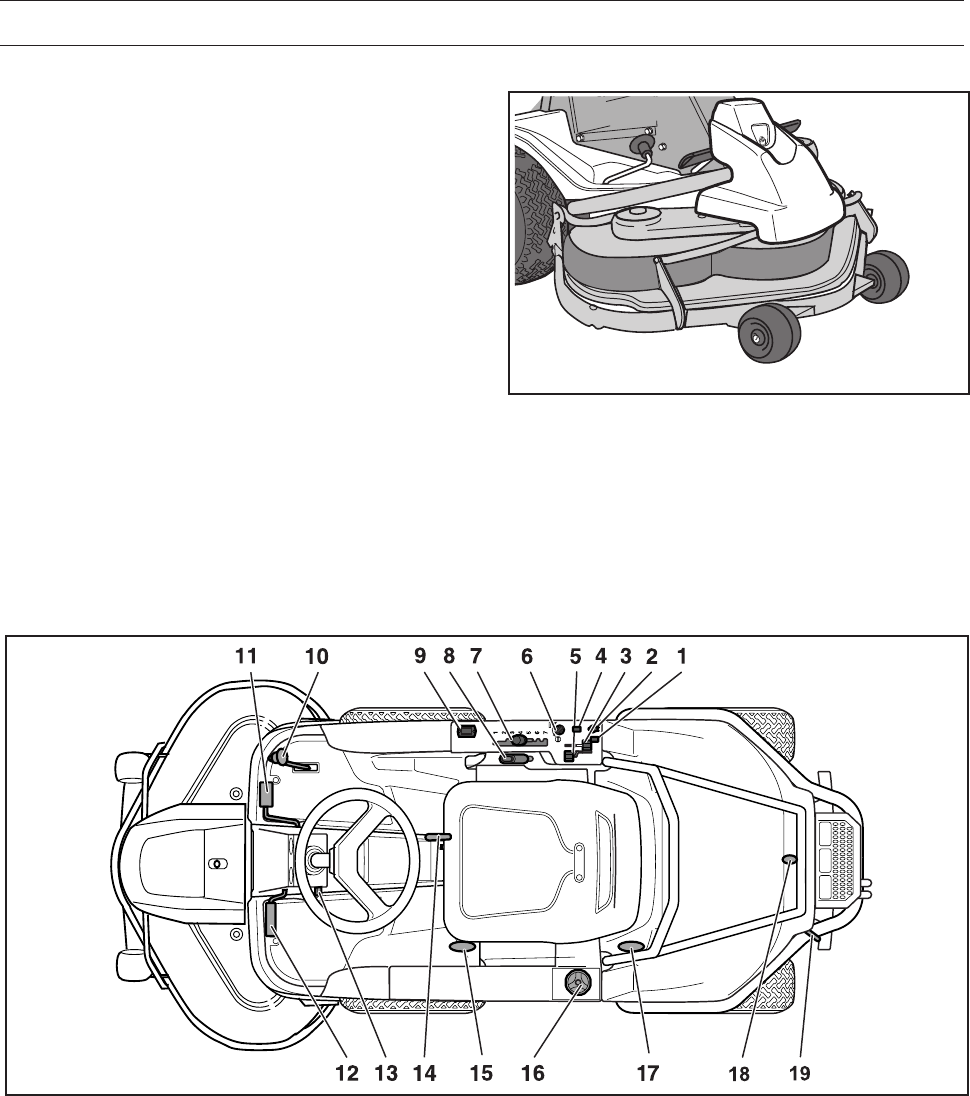
1. Switch for the power outlet
2. Power outlet
3. Throttle - regulates the engine speed
4. Switch for the lights
5. Choke Lever
6. Ignition key
7. Cutting height adjustment lever
8. Lifting lever for the cutting unit with lock button
9. Hour meter
Placement of Controls
10. Accelerator for reversing
11. Accelerator for driving forwards
12. Parking brake
13. Lock button for parking brake
14. Lever for adjusting the seat
15. Lever to disengage the driving front axle AWD
16. Fuel cap
17. Lever to disengage the driving rear axle AWD
18. Hood lock
19. Lever to disengage the drive on Pro 15, Pro 18
English – 13
8009-484
8009-485
PRESENTATION
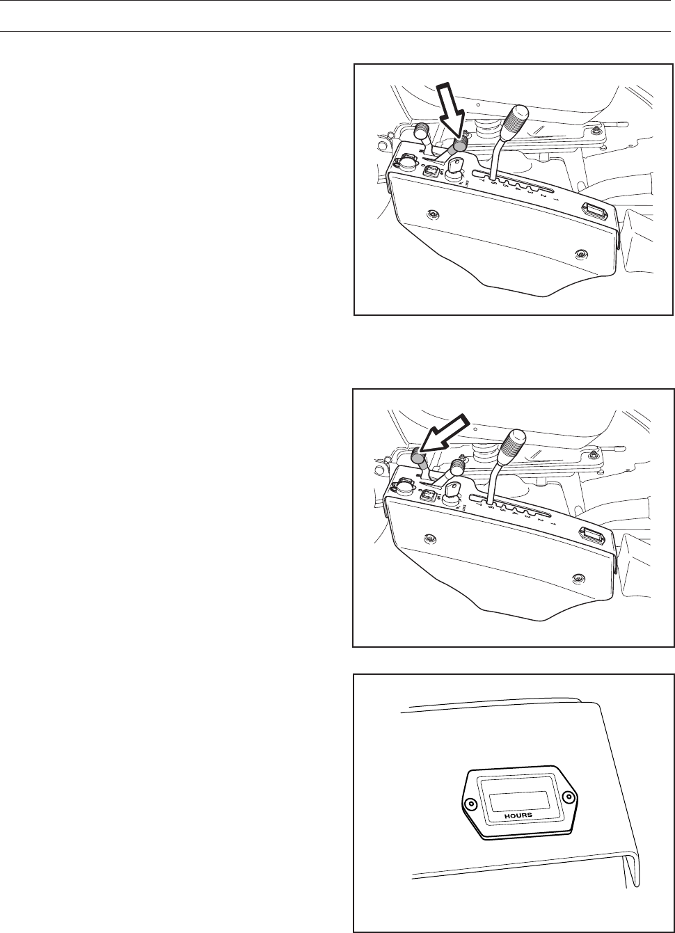
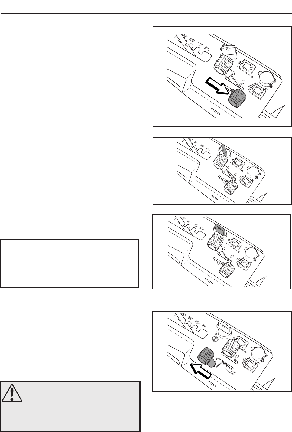
Choke Lever
The choke lever is used for cold starts in order to
provide the engine with a richer fuel mixture.
For cold starts, the lever shall be moved backwards
to its endpoint.
Throttle Control
The throttle is used to control the speed of the
engine and thereby also the rotation speed of the
blades.
In order to increase or decrease the engine speed,
the control is moved forwards or backwards
respectively.
Avoid idling the engine for long periods, as there is
a risk of carbon build-up on the spark plugs.
8009-498
Chronometer
The chronometer shows how many hours the
engine has been running. Any time when the
engine is not running but the ignition is switched on
is not registered. The last digit shows tenths of an
hour (6 minutes).
14 – English
8009-486
8009-487
PRESENTATION
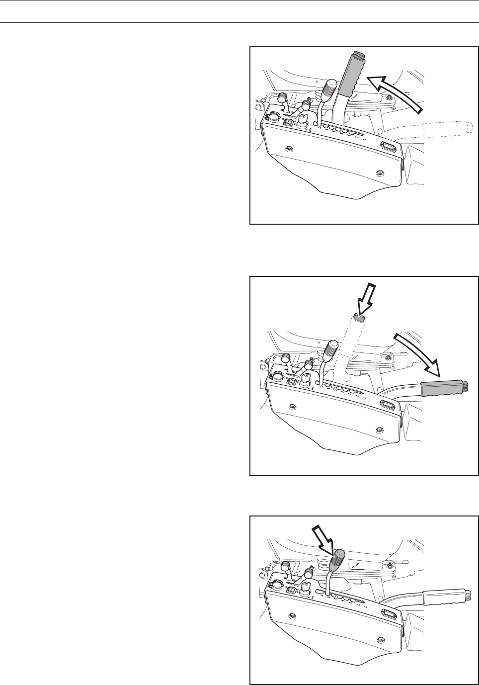
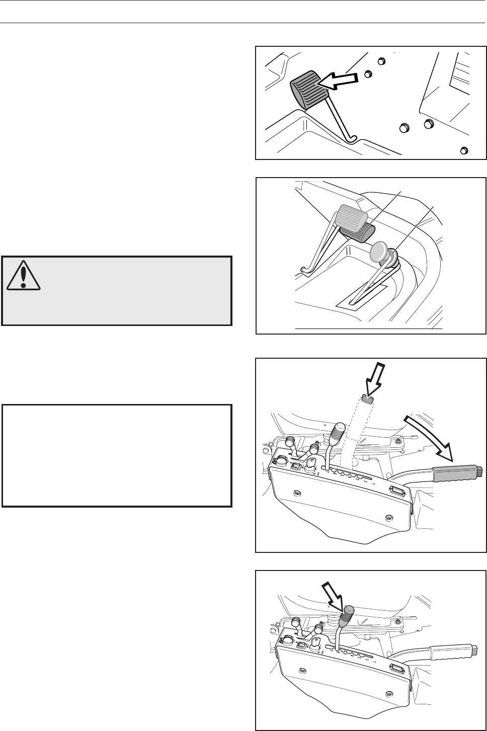
Lifting Lever for the Cutting Unit
The lifting lever is used to put the cutting unit in
either the transport or mowing positions.
1. Pull the lever backwards to the locked position
to engage the transport position.
The unit is raised and the blades stop rotating.
2. Depress the lock button and move the lever
forwards to engage the mowing position.
The unit is lowered and the blades begin to
rotate.
3. The lever can also be used to temporarily
adjust the cutting height, for example, with a
small mound in the lawn.
Raising the cutting unit
Lowering the cutting unit
8009-488
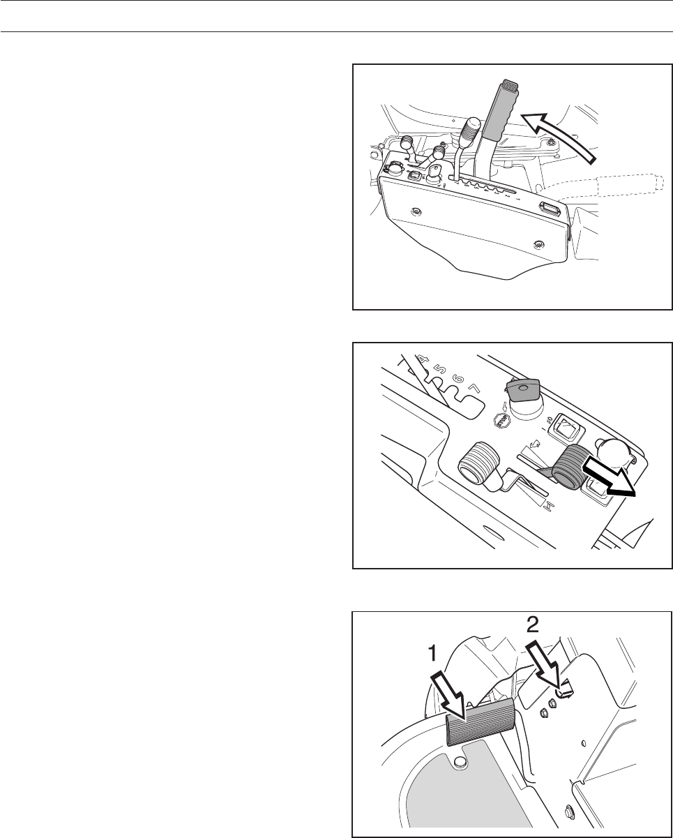
Cutting Height Adjustment Lever
Using the lever, the cutting height can be adjusted
in 7 different positions.
Combi 94 30-90 mm
(1 3/16" - 3 1/2")
Combi 103-unit 40-80 mm
(1 9/16" - 3 1/8")
Combi 112 40-100 mm
(1 9/16" - 3 7/8")
It is important that the air pressure in both front
wheels is equal, 60 kPa / 0.6 bar / 9 PSI, to
produce an even cutting height.
English – 15
8009-490
8009-491
8009-330
PRESENTATION
WARNING!
Petrol is highly flammable.
Observe caution and fill the tank
outdoors
(see the safety instructions).
Seat
The seat has a hinged mounting on the front edge
and can be folded forwards.
The seat can also be adjusted lengthways.
When making adjustments, the lever under the front
edge of the seat is moved to the left, after which the
seat can be moved backwards or forwards to the
desired position.
The seat springs can be adjusted by moving the
rubber blocks in their brackets on the underside of
the seat. Set both blocks in the front, centre or rear
positions.
Parking Brake
The parking brake is activated as follows:
1. Press down the parking brake pedal (1).
2. Press the lock button on the steering column (2)
in fully.
3. Release the parking brake pedal while keeping
the button pressed in.
The parking brake lock is automatically disengaged
when the brake pedal is pressed down.
Refuelling
The engine should be run on a minimum of 87-
octane unleaded petrol (not mixed with oil). It can
be beneficial to use environmentally adapted
alkylate petrol. See also ”Technical Data”
concerning methanol and ethanol fuels.
Do not fill the tank completely, leave an expansion
area of at least 2.5 cm (1").
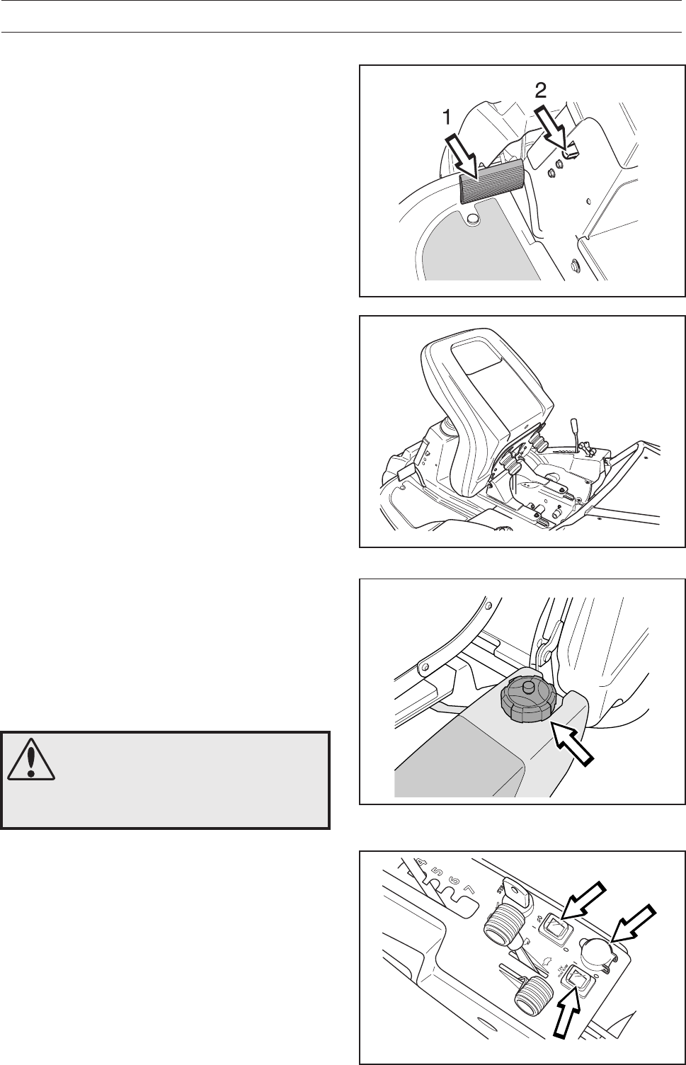
Lights and Power Outlet
The lights are switched on and off using the switch
(1) on the control panel.
A seat heater or mobile phone charger are
examples of articles that can be connected to the
power socket (2). The power outlet is switched on
and off using power switch (3) on the control panel.
The voltage is 12V. The electrical outlet socket is
fuse protected by its own fuse.
8009-546
12
3
16 – English
MAX 15
6017-236
DRIVING
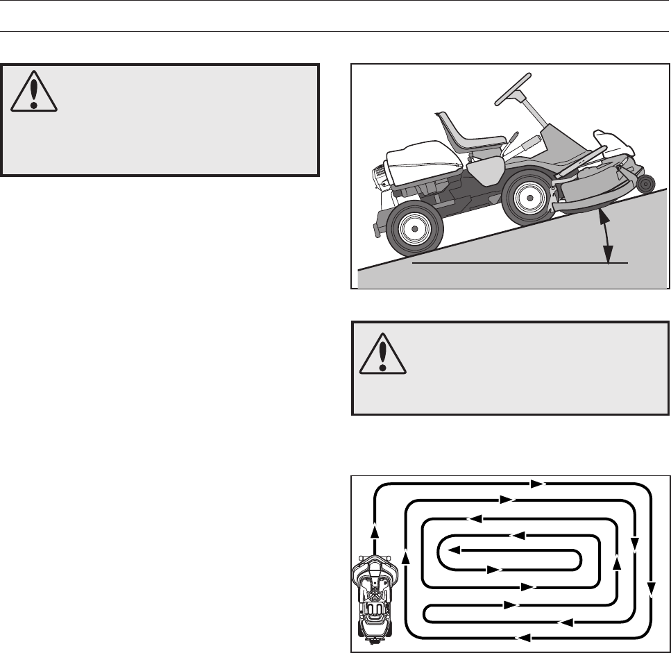
WARNING!
Do not use the Rider on ground
that slopes more than 15°. Mow
upwards and downwards on
slopes, never sideways. Avoid
sudden directional changes.
6007-212
Mowing patterns
WARNING!
Clear the lawn of stones and other
objects that can be thrown out by
the blades.
Mowing Tips
•Find and mark out any stones and other fixed
objects to avoid colliding with them.
•Start with a high cutting height and reduce it
until the desired mowing result is obtained.
•The best mowing result is achieved with high
engine revs (the blades rotate quickly) and low
speed (the Rider moves slowly).
If the grass is not too long and thick the driving
speed can be increased without significantly
impairing the mowing result.
•The finest lawns are obtained if they are mown
frequently. Mowing will be more even and the
clippings will be more evenly distributed across
the area.
The overall mowing time will not be longer as
higher driving speeds can be selected without
impairing the mowing result.
•Avoid mowing wet lawns. The mowing result will
be poorer as the wheels will sink into the soft
lawn.
•Rinse off the underside of the cutting unit after
use with water, do not use a high pressure
washer. When cleaning, the cutting unit shall be
moved into the service position.
•It is important to mow frequently when mowing
with the mulching function.
English – 17
Clutch Control
The clutch control must be pulled out in order for
the Rider to be moved when the engine is shut off.
The figure shows the clutch control pulled out.
8009-142
Pro 15, Pro 18
Pro 18 AWD has one control for the front axle and
one control for the rear axle.
Pull the controls to their end positions. Do not use an
intermediate position.
Rear Axle
The control is positioned on the inside of the left
rear wheel.
• Forward control (pulled out), drive system
disengaged.
• Rear control (pushed in), drive system engaged.
Front Axle
The control is positioned on the inside of the left
front wheel.
• Rear control (pulled out), drive system disengaged.
• Front control (pushed in), drive system engaged.
8009-690
Pro 18 AWD rear
8009-700
Pro 18 AWD front
DRIVING
18 – English
8009-486
8009-492
8009-602
DRIVING
• Read the safety instructions and the
presentation of the Rider before starting.
• Perform the daily maintenance before starting,
see ”Maintenance\Maintenance schedule”.
• Adjust the seat to the desired position.
3. Move the throttle to the middle position.
8009-489
IMPORTANT INFORMATION
The air intake grille in the engine cover
behind the driver’s seat must not be
blocked by, for example, clothing, leaves,
grass or dirt.
Impaired cooling of the engine. Risk of
major engine damage.
Starting the Engine
1. Activate the parking brake by pressing down the
pedal. Press in the release button if necessary.
The engine can not be started if the parking
brake is not pressed down.
Before Starting
8009-328
2. Raise the cutting unit by pulling the lever
backwards to the locked position (transport
position) and apply the parking brake.
English – 19
8009-495
8009-496
6. When the engine starts, immediately release
the ignition key so that it returns to the neutral
position.
DRIVING
WARNING!
Never run the engine indoors, in
enclosed or badly ventilated
areas. Engine exhaust fumes
contain poisonous carbon
monoxide
8009-569
8009-494
5. Turn the ignition key to the start position.
4. If the engine is cold, the choke control shall be
moved backwards to its end position.
7. Move the choke lever gradually forward once
the engine has started.
8. Set the desired engine speed with the throttle.
Allow the engine to run at a moderate speed,
”half throttle”, for 3–5 minutes before loading it
too heavily.
When mowing, use 3/4 to full throttle.
IMPORTANT INFORMATION
Do not run the starter motor for more than
5 seconds at a time. If the engine does not
start, wait about 15 seconds before trying
again.
20 – English
8009-487
8009-488
IMPORTANT INFORMATION
The life span of the drive belts is increased
significantly if the engine runs at a low
speed when the blades are engaged.
Therefore apply full throttle first when the
cutting unit has been moved to the mowing
position.
DRIVING
3. Press in the lock button on the lifting lever and
lower the cutting deck.
4. Select the required cutting height (1-7) using
the cutting height lever.
It is important that the air pressure in both front
wheels is equal, 060 kPa / 0.6 bar / 9 PSI, to
produce an even cutting height.
6007-208
6004-206
Driving the Rider
1. Release the parking brake by first pressing
down the parking brake pedal and then
releasing the brake pedal.
2. Carefully press down one of the pedals until the
required speed is attained.
Pedal (1) is pressed down to travel forwards
and pedal (2) to reverse.
WARNING!
Make sure that no branches can
interfere with the pedals when
mowing under bushes.
Risk for unintentional manoeuvring.
1
2
Braking
Release the drive pedals. The machine slows and is
stopped by the drive system. Do not use the parking
brake as the drive brake.
Quicker braking is possible if you press down the
drive pedal for the opposite direction.
English – 21
8009-486
8009-497
Stopping the Engine
If the engine has been worked hard, it is preferable
to let the engine idle for a minute so it is running at
its normal working temperature when it is stopped.
Avoid idling the engine for long periods, as there is
a risk of carbon build-up on the spark plugs.
1. Lift up the cutting unit by pulling the lever
backwards to its locked position.
2. Move the throttle control to the ”MIN” position”.
Turn the ignition key to ”STOP”.
DRIVING
8009-490
3. When the Rider is at a standstill, hold down the
parking brake (1) and press in the lock button
(2).

22 – English
Page
25 50 100 300
Maintenance
Maintenance Schedule
The following is a list of maintenance procedures that must be performed on the rider. For points marked
with footnote number 4, turn to an authorised service representative.
● = Described in this operator’s manual. ❍ = Not described in this operator’s manual.
Daily main-
tenance
before after
MAINTENANCE
Maintenance
interval hours
Weekly3)
main-
tenance
At least
once
a year
Check for fuel and oil leaks - ❍
Check the parking brake 15 ●
Check the engine’s oil level (every refuelling) 59 ●
Check the fuel pump’s air filter 28 ●●
Check the safety switch, seat 33 ●
Check the safety switch, lifting lever 33 ●
Check the safety switch, pedal system 33 ●
Check/clean the engine’s cooling air intake. 31 ●●
Check the cutting unit: 45 ●
• mounting of blades 51 ●
• condition of the blades (sharpness, shape, etc) 51 ●
Check the steering cables (any play, etc.) 25 ●
Check fastenings (screws, nuts, etc.) - ❍
Start the engine and blades,
listen for abnormal sounds - ❍
Clean under the cutting unit 48 ●
Clean the transmission’s cooling air intake 28 ●●
Inspecting the muffler 27 ●
Check the battery’s acid level 31 ●
Check the transmission oil level 61 ●
Check the condition of belts, belt pulleys, etc. - ❍
Check for damage - ❍
Check the tyre pressures (60 kPa / 9 PSI) 35 ●
Check to ensure that the cable holder
in the middle is undamaged - ❍
Clean thoroughly around the engine 31 ●
Clean carefully around the muffler 31 ●
Clean thoroughly around the transmission (s) 28 ●
Clean around all belts, belt pulleys, etc. - ●
Lubricate the belt tensioner (nipple) 59 ●
Lubricate the three-point link 58 ●
Lubricate the driver seat 58 ●
Lubricate all cables 56 ●
Lubricate links in the cutting unit 56 ●
Clean the frame tunnel - ❍
Lubricate the pedal mechanism
in the frame tunnel 57 ●
Lubricate the hydrostatic cable with linkage 60 ●
Lubricate the parking brake cable 61+63 ●
Lubricate the throttle 58 ●
Lubricate the choke control 58 ●
Lubricate the guide chain in the frame tunnel 57 ●
Check the steering cables in the frame tunnel 25 ●

English – 23
25 50 100 300
Lubricate the right, rear axle bearing
Pro 18 AWD 63 ●
Clean the engine’s cooling air intake 31 ●●
Clean the air filter’s pre-cleaner
(foamed plastic) 29+30 ●●
Change the engine oil1) 60 ●●
1) ●1)
Clean the air filter’s filter cartridge 2)
(paper filter) 29+30 ●●
Check/adjust the cutting height 45 ●●
Check/adjust the parking brake 26 ●●
Inspect the flame proofing/spark arrestor
(extra equipment) - ❍❍
Replace the engine oil filter (every 200 hours) 62 ●●
Replace the hydraulic oil filter (every 200 hours)5) 62 ●●
Clean/replace the spark plugs 32 ●●
Change the inline fuel filter 28 ●●
Clean the pulse air filter 28 ●●
Clean the cooling fins 28 ●●
Check the play in the engine valves4) -❍❍
Check the need of an oil change4) and filter
replacement 5) in the gearbox/hydraulic system - ❍❍
(every 2006)/500 hours)
Replace the suction filter in the hydraulic tank
(every 200 hours)6) -❍❍
Replace the air filter’s pre-cleaner
(foamed plastic)2) 29+30 ●●
Replace the air filter (paper filter) 2)
(every 200 hours) 29+30 ●●
Perform the 300-hour service4) - ❍❍
1) First change after 8 hours. When operating with a heavy load or at high ambient temperatures, replace
every 50 hours. 2) Maintenance and replacement are required more often in dusty conditions. 3) With daily
use, the Rider should be lubricated twice weekly. 4) Performed by an authorised service workshop.
5) Pro 18 only. 6) Pro 18 AWD only. Replace first after 50 hours.
MAINTENANCE
●= Described in this operator’s manual.
❍= Not described in this manual.
WARNING!
No service operations may be performed on the engine or cutting unit unless:
• The engine has been stopped.
• The ignition key has been removed.
• The ignition cables have been removed from the spark plugs.
• The parking brake is on.
• The cutting unit is disengaged.
Maintenance
interval hours
Daily main-
tenance
before after
Weekly3)
main-
tenance
At least
once
a year
Maintenance Page
24 – English
8009-509
6017-219
MAINTENANCE
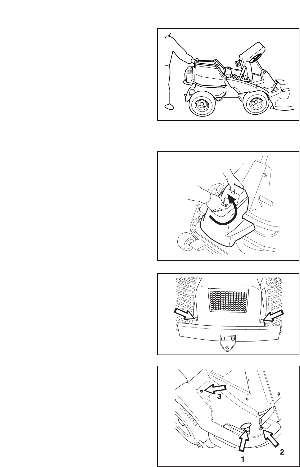
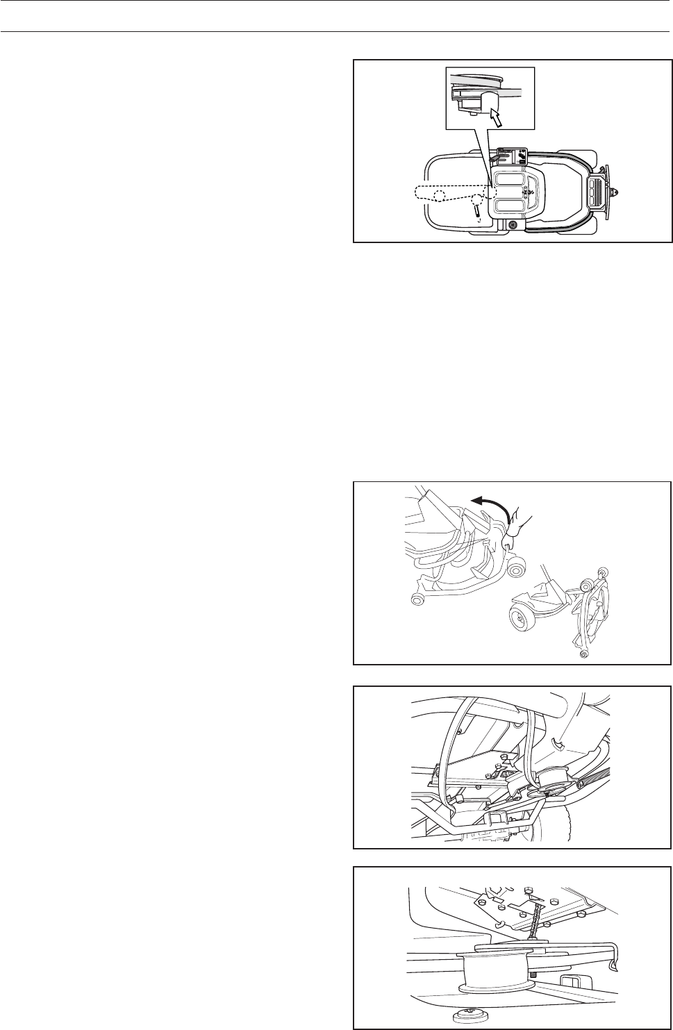
Front Cover
Loosen the snap-in lock and lift off front cover.
Dismantling the Rider Covers
The engine becomes accessible for service when
the engine cover is opened.
Engine Cover
1. Pull the seat forward to its foremost position.
2. Fold up the seat.
3. Turn the cover lock on the top of the engine
cover anti-clockwise a 1/4 turn.
4. Open the engine cover forwards.
If necessary the engine cover can be lifted off by
removing the hinge pins.
Transmission Cover
Loosen both screws (one on each side) and lift off
the transmission cover.
8009-603
Right-hand Wing Cover
Remove the knob (1), the screws (2 and 3) and lift
off the cover.
8009-499
English – 25
Left-hand Wing Cover
Loosen the screws (2) and lift off the cover.
8009-501
8009-505
6008-212
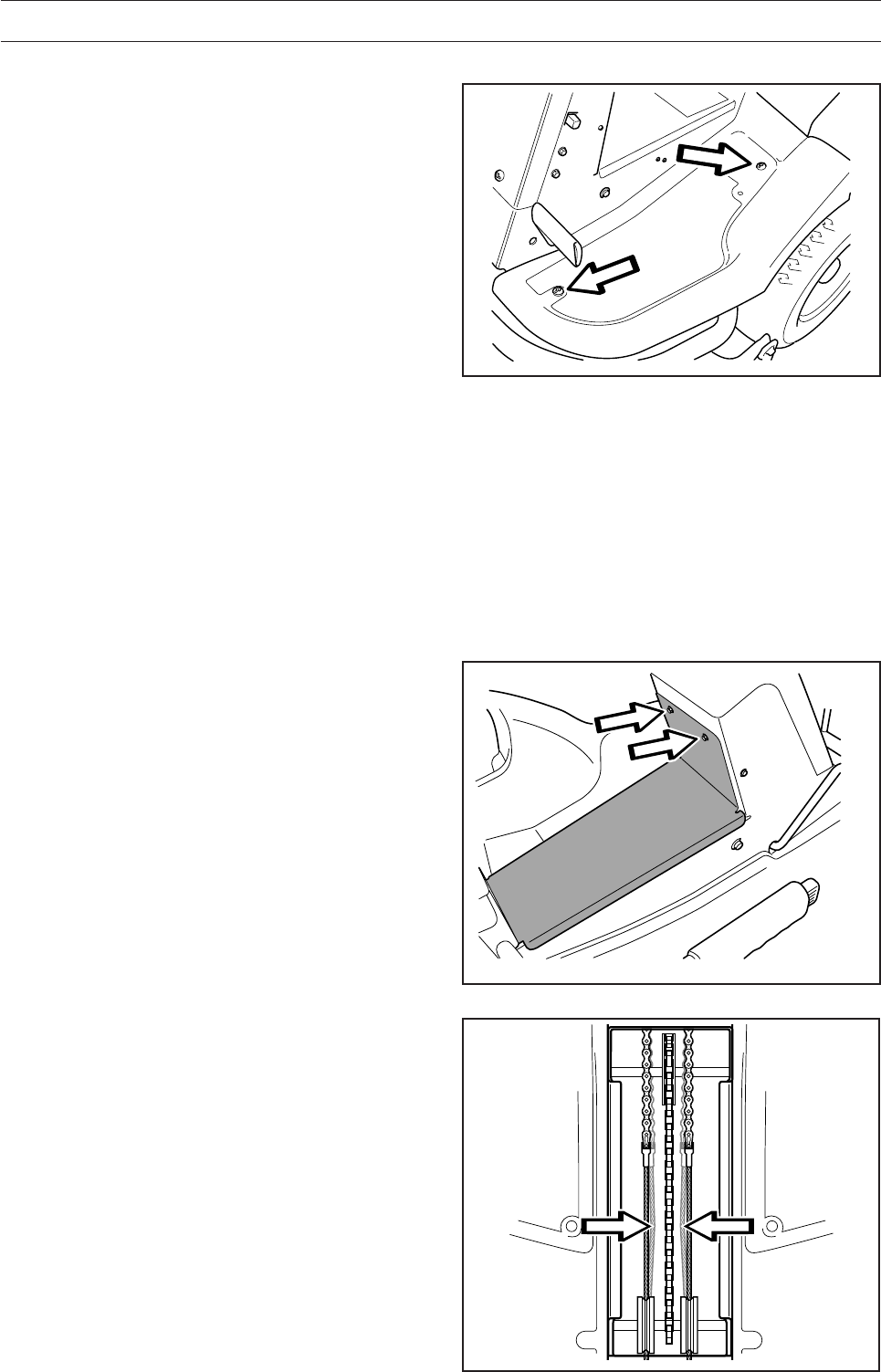
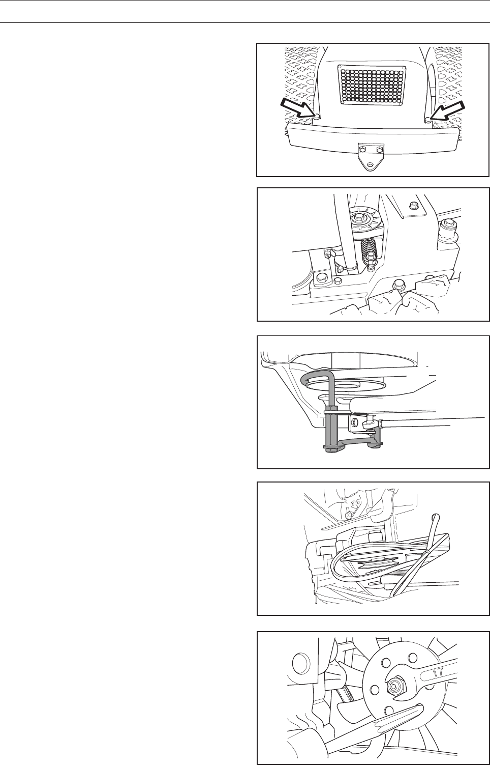
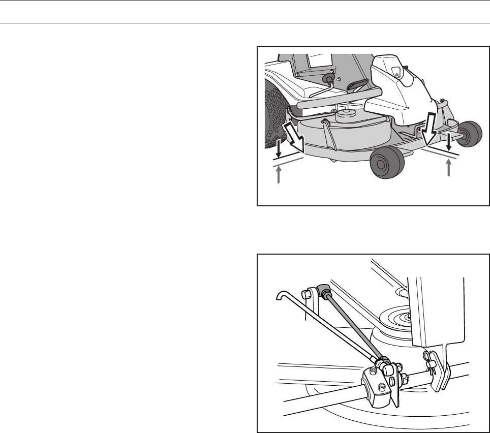
2. Check the tension of the steering cables by
squeezing the cables together (at the arrows).
It should be possible to squeeze the cables so
that the distance between them is half the size,
without using too much force.
Checking and Adjusting the Steering
Cables
The steering is governed by means of cables.
After a period of use these can become stretched,
which means the steering setting may have
changed.
Steering is checked and adjusted as follows:
1. Remove the frame plate by loosening the
screws.
MAINTENANCE
26 – English
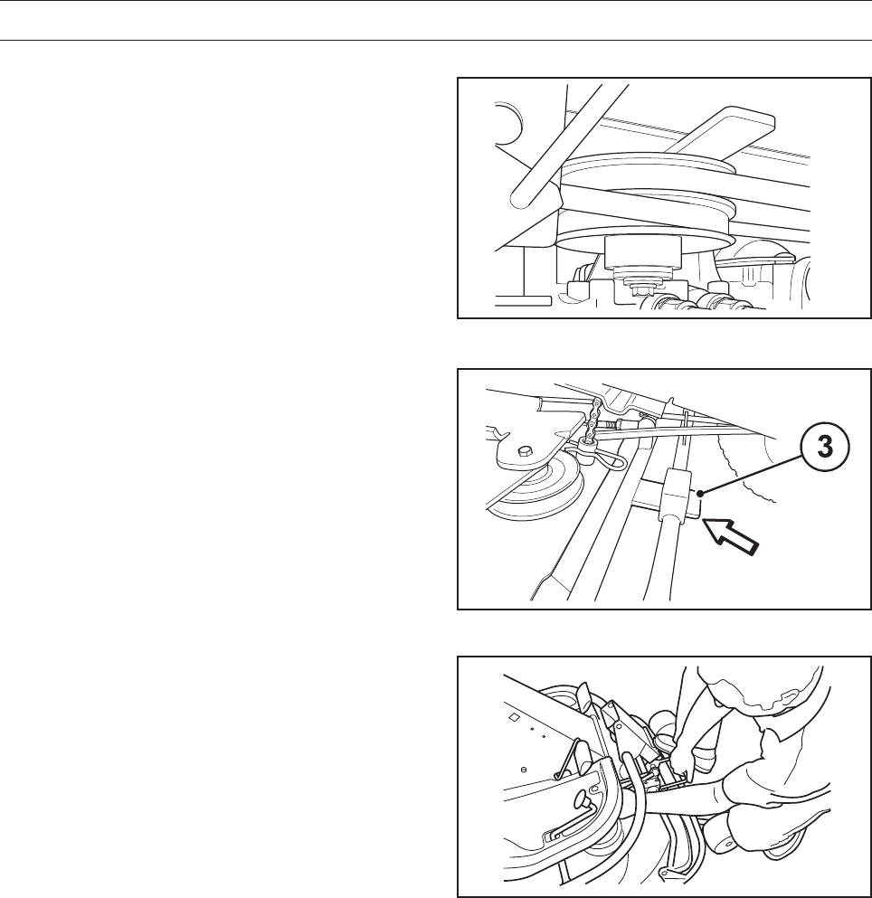
6008-010
MAINTENANCE
3. If necessary, the wires can be adjusted by
tightening the adjuster nuts on each side of the
steering collar.
Do not tension the cables too much, they should
only
be tightened
against the steering collar.
Hold the wire so it does not twist.
If you only tension one side the steering wheel’s
centre position may change.
Check the wire tension as set out in point 2
after you have made the adjustment.
B
A
6020-005
WARNING!
A poorly adjusted parking brake
can result in reduced braking ability.
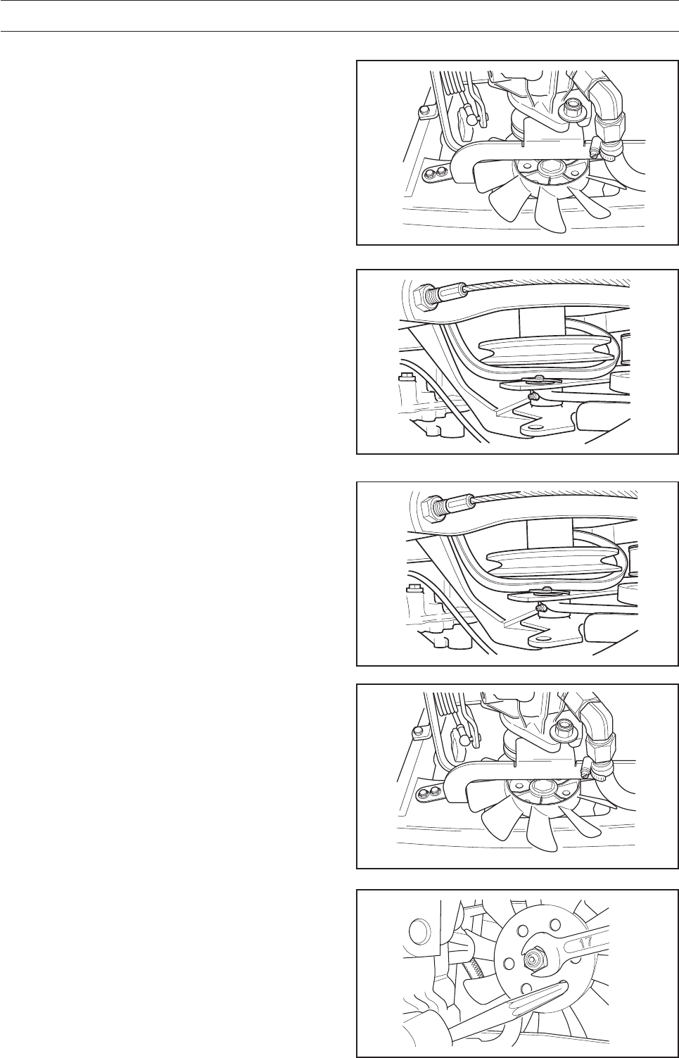
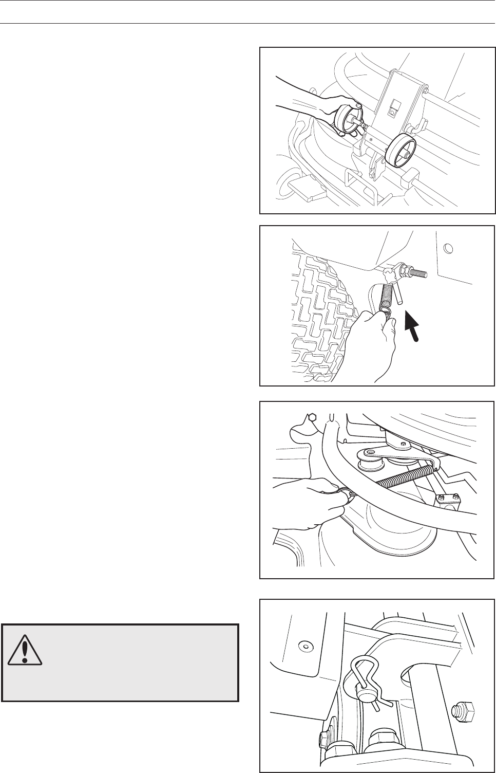
Adjusting the Parking Brake Pro 15, Pro 18
The parking brake is adjusted as follows:
1. Remove the transmission cover.
2. Unhook the spring (A) from the screw (B).
3. Check that the parking brake is not on.
4. Adjust the play between the casing and the
adjustment screw to 1 mm when one pulls the
casing.
Adjust with the nuts on the adjustment screw.
5. Tighten the nuts moderately to avoid damaging
the threads.
6. Replace the spring (A).
7. Check that the parking brake works.
Adjusting the Parking Brake Pro 18 AWD
Check that the parking brake is adjusted correctly
by placing the machine on a slope with the front
and rear axles disengaged. Apply and lock the
parking brake. When the machine does not stand
still, the parking brake should be adjusted accord-
ing to the following.
1. Remove the left-hand wing cover.
2. Check that the parking brake is not on.
3. Adjust the play between the casing and the
adjustment screw to 1 mm (0.040") when one
pulls the casing. This gives play on the pedal of
approximately 40 mm (1.5"). Adjust using the
nuts on the adjustment screw.
4. Tighten the nuts moderately to avoid damaging
the threads.
5. Check that the parking brake works.
6. Assemble the left-hand wing cover.
8009-501
8009-688
English – 27
8009-145
8009-683
MAINTENANCE
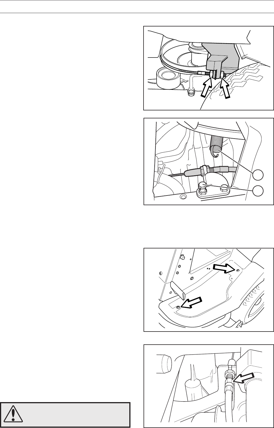
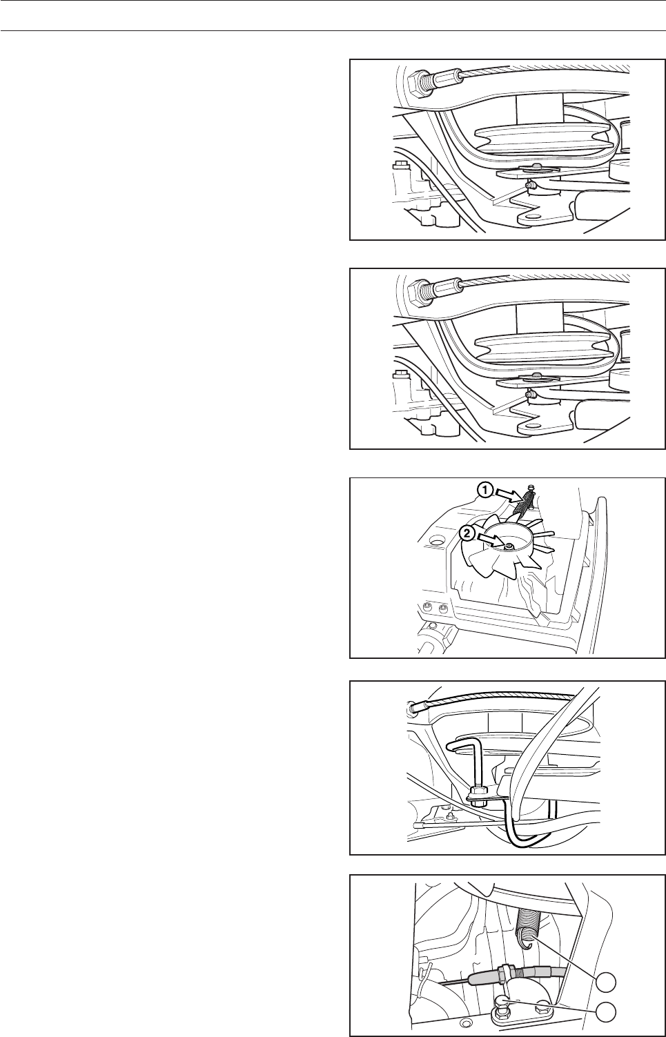
Checking and Adjusting the Choke Cable
If the engine produces black smoke or is difficult to
start, this can be because the choke cable is
incorrectly adjusted (upper cable).
If doubts arise, contact your service representative.
If adjustments are necessary, they can be made as
follows:
1. Loosen the clamping screw for the cable’s
outer casing and move the choke lever to the
full choke position.
2. Check that the choke cable is mounted in the
upper lever, see illustration.
3. Pull the choke cable’s outer casing as far to the
right as possible and tighten the clamping
screw.
8009-144
Checking and Adjusting the Throttle
Cable
Check that the engine responds to throttle
increases and that a good engine speed is attained
at full throttle.
If doubts arise, contact your service representative.
If adjustments are necessary, they can be made as
follows for the lower cable:
1. Loosen the clamping screw for the cable’s
outer casing and move the throttle to the full
throttle position.
2. Check that the throttle cable is mounted in the
correct hole in the lower lever, see illustration.
3. Push the throttle cable’s outer casing as far to
the left as possible and tighten the clamping
screw.
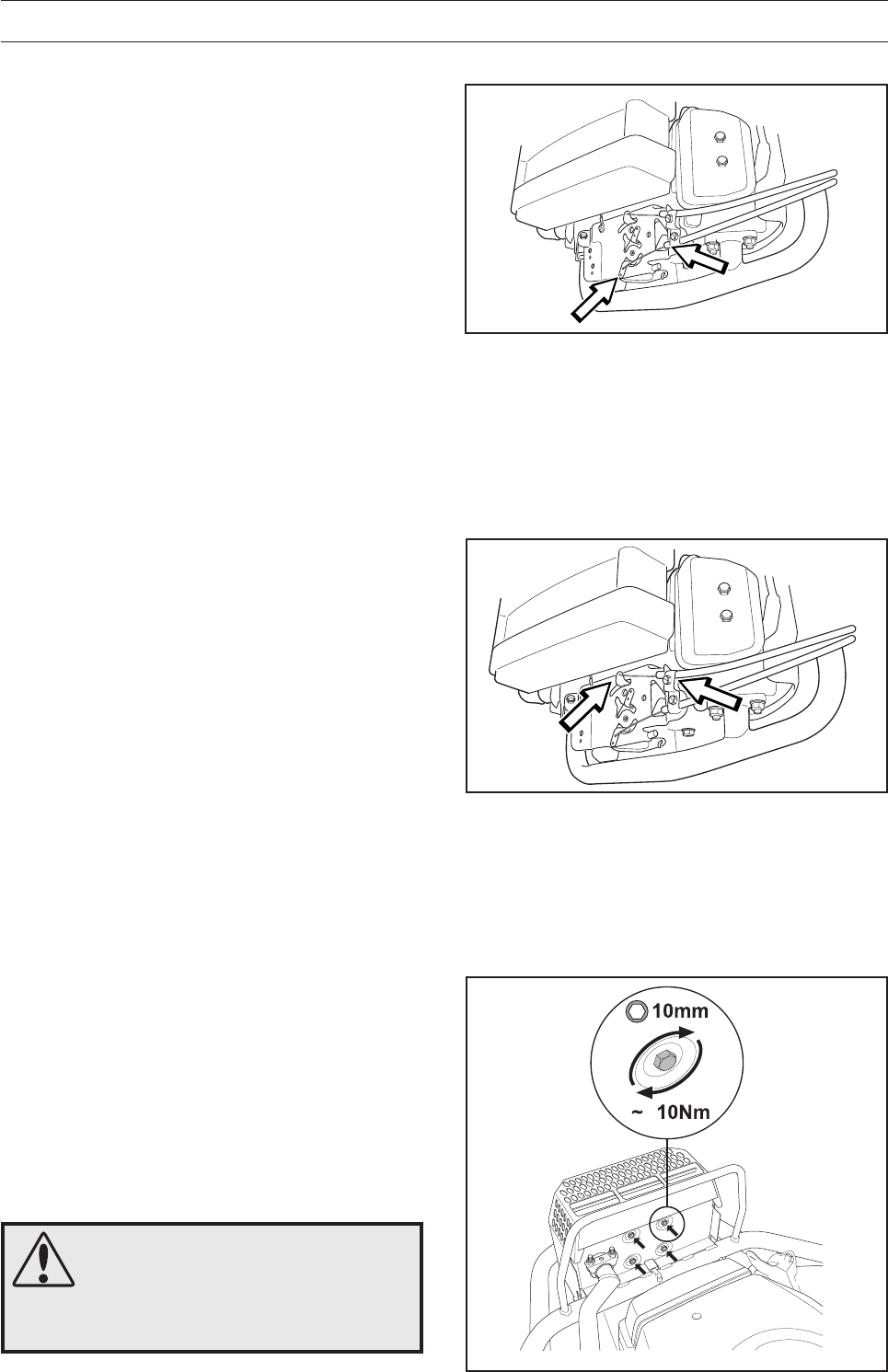
Inspecting the Muffler
Check regularly that the muffler is complete and
secured correctly.
Temperature variations and vibrations can mean
that the tightening torque for the screws drops. The
screws should be checked when servicing to
guarantee the correct torque. The tightening torque
should be about 10 Nm. Never use a defective
muffler.
WARNING!
The muffler gets very hot in use
and remains so for a short time
afterwards. Contact can result in
burns. Remember the risk of fire.
28 – English
8009-147
6017-235
Checking the Fuel Pump’s Air Filter
Check regularly that the fuel pump’s air filter is not
clogged by dirt.
The filter can be cleaned using a brush, if
necessary.
1. Remove the two screws holding the fuel pump.
2. Move the pump to one side without loosening
the hoses and brush clean the filter.
3. Replace the fuel pump.
MAINTENANCE
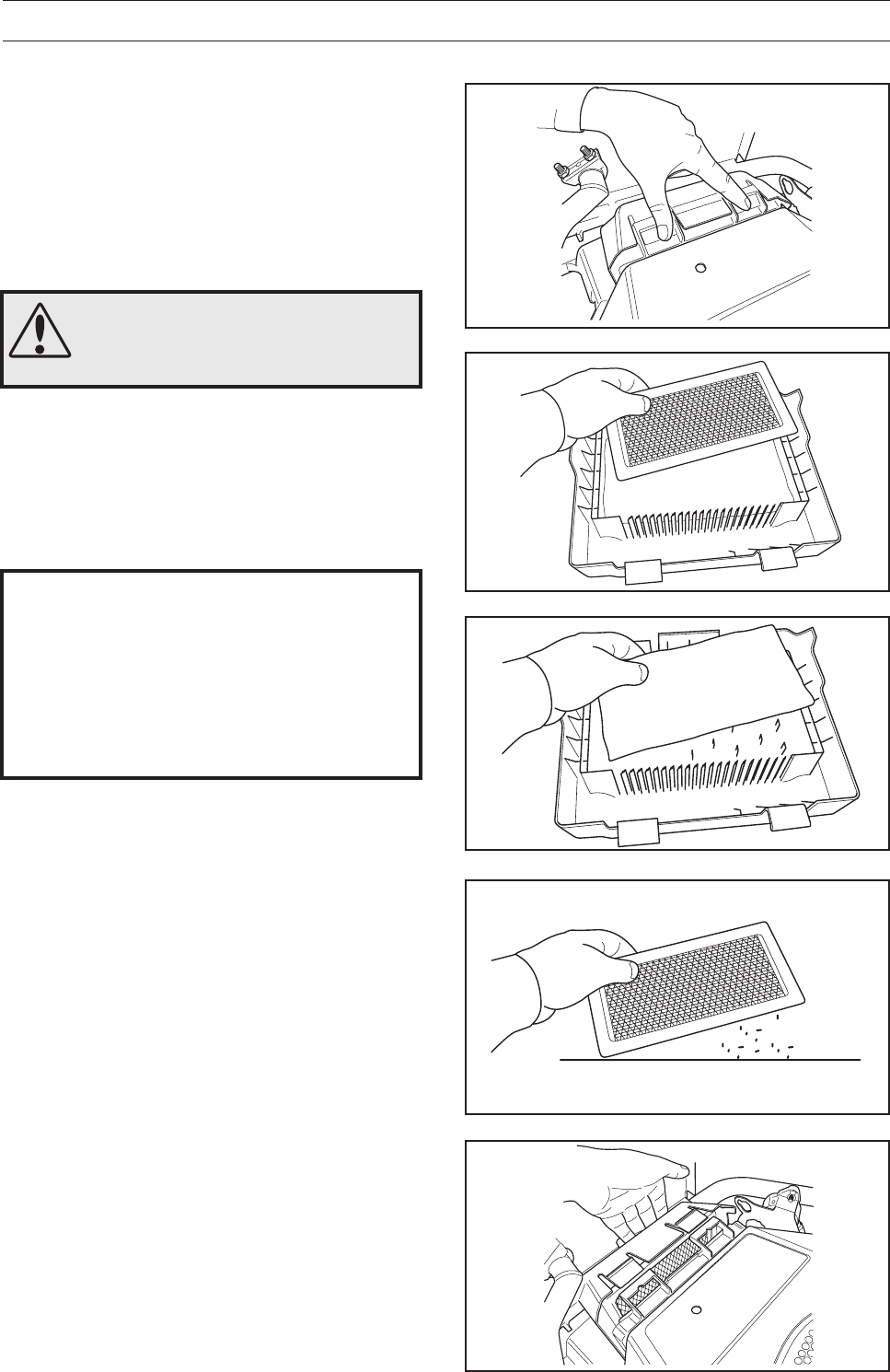
Air Supply Exhaust Pipe
Cleaning the Pulse Air Filter
1. Fold up the engine cover.
2. Loosen the four snap catches, remove the
cover, and remove the filter.
3. Blow the filter clean with compressed air.
Replace the filter if it is damaged or cannot be
blown clean.
4. Place the filter back in the cover and fasten the
cover with the snap catches. Replace the
engine cover.
8009-146
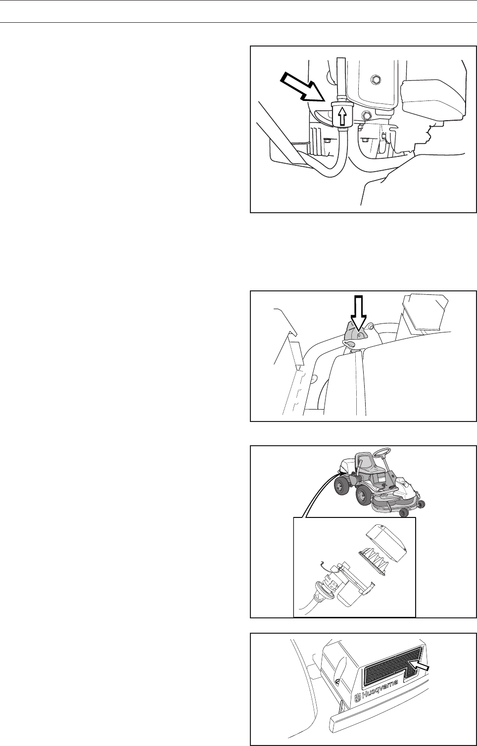
Replacing the Fuel Filter
Replace the fuel filter mounted on the supply line
after every 100 hours (once per season) or more
frequently if it is clogged.
Replace the filter as follows:
1. Open the engine cover.
2. Move the hose clamps away from the filter.
Use a pair of flat pliers.
3. Pull the filter loose from the hose ends.
4. Push the new filter into the hose ends. Position
the filter with the ”FLOW” arrow pointing up
towards the fuel pump. If necessary, a soap
solution can be applied to the ends of the filter
to simplify assembly.
5. Move the hose clamps back toward the filter.
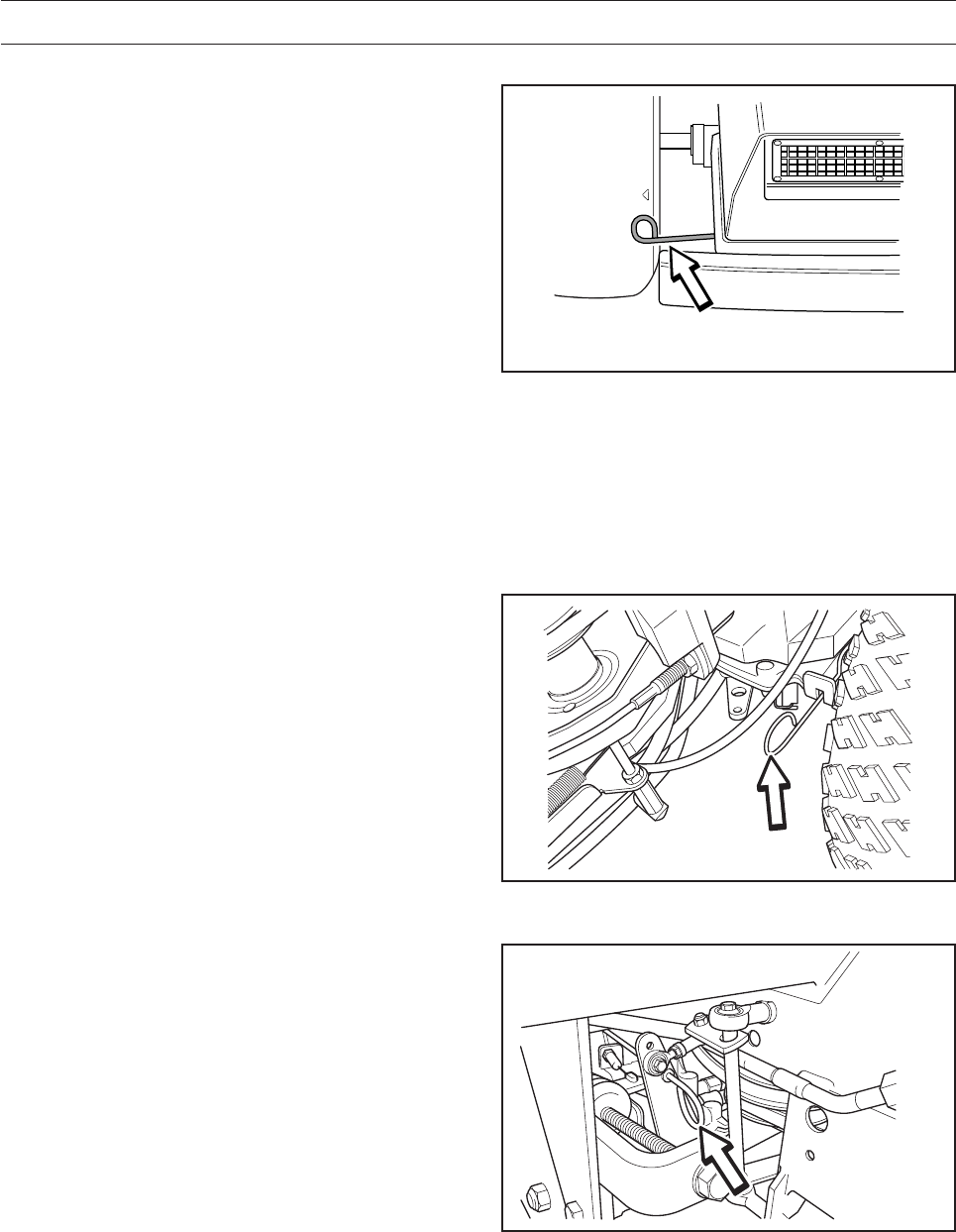
Checking the Transmission Air Intake
Check to ensure that the transmission’s air intake
in the transmission cover is not clogged.
Remove the transmission cover and clean any
grass cuttings from the transmission’s cooling fins
if necessary.
Cooling is impaired if the air intake is blocked or
the transmission housing is dirty, this can result in
damage to the transmission. 6017-106
English – 29
MAINTENANCE
8009-446
8009-447
8009-448
8009-450
8009-452
Replacing the Air Filter Pro 15
If the engine seems weak or runs unevenly, the air
filter may be clogged. If run with a soiled air filter,
carbon can build-up on the spark plugs and lead to
malfunction.
Consequently, it is important to periodically replace
the air filter (see ”Maintenance \ Maintenance
Schedule” for the correct service interval).
IMPORTANT INFORMATION
Never run the engine when the air filter
has been removed.
Do not use compressed air to clean the
paper filter. Do not wash the paper filter.
Filters should not be oiled. They should
be assembled dry.
2. Take the prefilter and the paper filter out of the
air filter unit.
3. Clean the prefilter by washing with water and a
cleaning agent.
4. Dry the prefilter well.
5. Tap the paper filter against a solid surface to
remove dust. If the paper filter is still dirty, it must
be replaced with a new filter.
Always replace the paper filter after every
200 hours.
6. Refit the prefilter and the paper filter in
the air filter unit.
7. Refit the air filter unit by first pressing in the lugs
at the bottom of the unit and then pushing so
that the catches lock.
WARNING!
Allow the exhaust system to cool
before servicing. Risk of burns.
Replacing the air filter is carried out as follows:
1. Remove the air filter unit by pressing the
catches with your fingers.
30 – English
8009-148
8009-149
8009-150
8009-151
MAINTENANCE
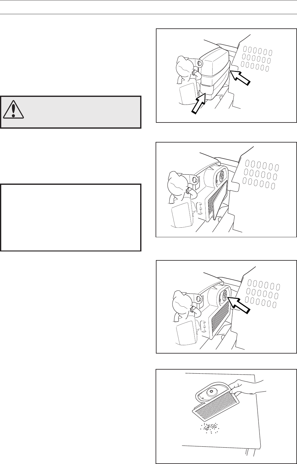
Replacing the Air Filter Pro 18
If the engine seems weak or runs unevenly, the air
filter may be clogged. If run with a soiled air filter,
carbon can build-up on the spark plugs and lead to
malfunction.
Consequently, it is important to periodically replace
the air filter (see ”Maintenance \ Maintenance
Schedule” for the correct service interval).
WARNING!
Allow the exhaust system to cool
before servicing. Risk of burns.
3. Undo both of the snap catches and lift off the
cover on the air filter housing.
4. Remove the foam rubber pre-filter and clean
using a mild detergent.
Squeeze it dry with a clean cloth.
5. Remove the wing nut in the air filter and remove
the paper filter. Tap the paper filter against a
solid surface to remove dust. If the paper filter
is still dirty, it must be replaced.
6. Refit the air filter as follows:
Mount the paper filter in the air filter housing
and tighten the wing nut.
7. Insert the prefilter on the rectangular part of the
paper filter.
8. Replace the cover over the air filter housing.
Move the cover up from below and ensure that
the prefilter does not fall out of position. Secure
with both snap catches.
IMPORTANT INFORMATION
Never run the engine when the air filter
has been removed.
Do not use compressed air to clean the
paper filter. Do not wash the paper filter.
Filters should not be oiled. They should
be assembled dry.
Cleaning/replacement of the air filter is carried out
as follows:
1. Loosen the rubber strap under the seat and
open the engine cover.
2. Steer fully in one direction (AWD)
English – 31
8009-489
Cooling air intake
8009-152
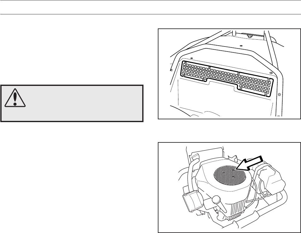
WARNING!
The cooling air intake rotates
when the engine is running.
Watch your fingers.
MAINTENANCE
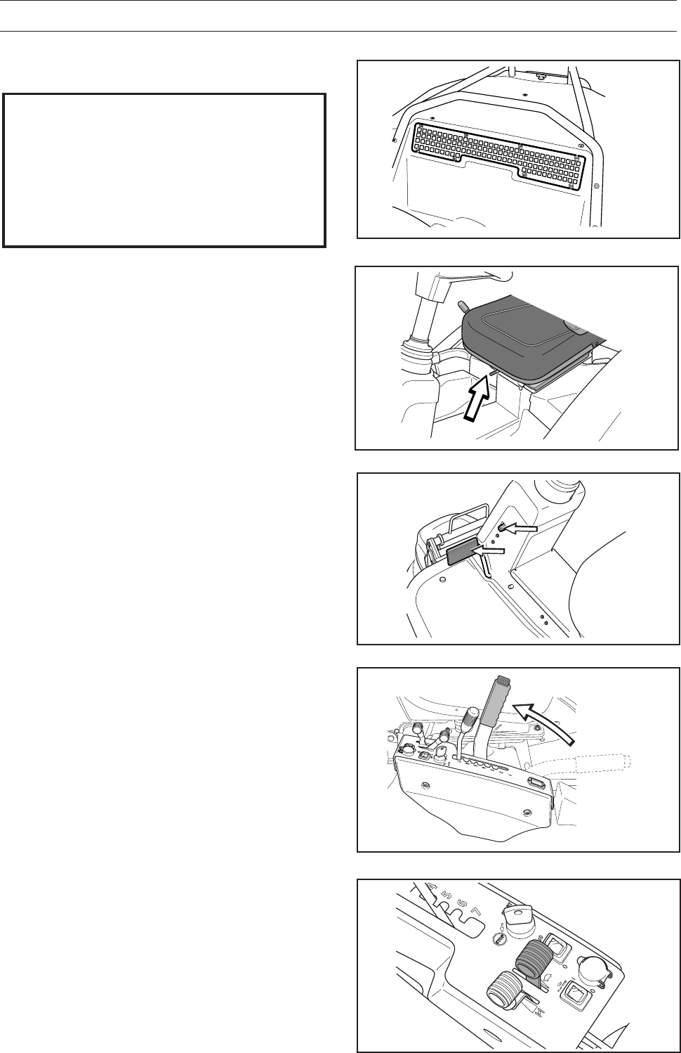
Checking the Engine’s Cooling Air
Intake
Clean the air intake grille in the engine cover
behind the driver’s seat.
Open the engine cover.
Air intake grille
Cleaning the Engine and Muffler
Keep the engine and muffler free from grass
cuttings and dirt. Grass cuttings steeped in petrol or
oil on the engine can increase the fire risk and
impair cooling.
Allow the engine to cool before cleaning. If the dirt
is mixed with oil, remove it using a degreasing
agent otherwise just water and a brush.
Grass cuttings around the muffler dry quickly and
constitute a fire risk. Brush or wash them off when
the muffler is cold.
Check that the engine cooling air intake is free of
leaves, grass, and dirt.
Check the air duct, located on the inside of the
engine cover, ensure it is clean and does not rub
against the cooling air intake.
A clogged air intake grille, air duct or cooling air
intake impairs the cooling of the engine, which may
result in engine damage.
32 – English
6008-216
8011-054
MAINTENANCE
WARNING!
Actions with acid contact
External: Rinse thoroughly with water.
Internal: Drink large quantities of water or milk.
Contact a doctor as soon as possible.
Eyes: Rinse thoroughly with water. Contact
a doctor as soon as possible.
The battery emits explosive gases. Sparks,
flames, and cigarettes must not be present in
the vicinity of the battery.
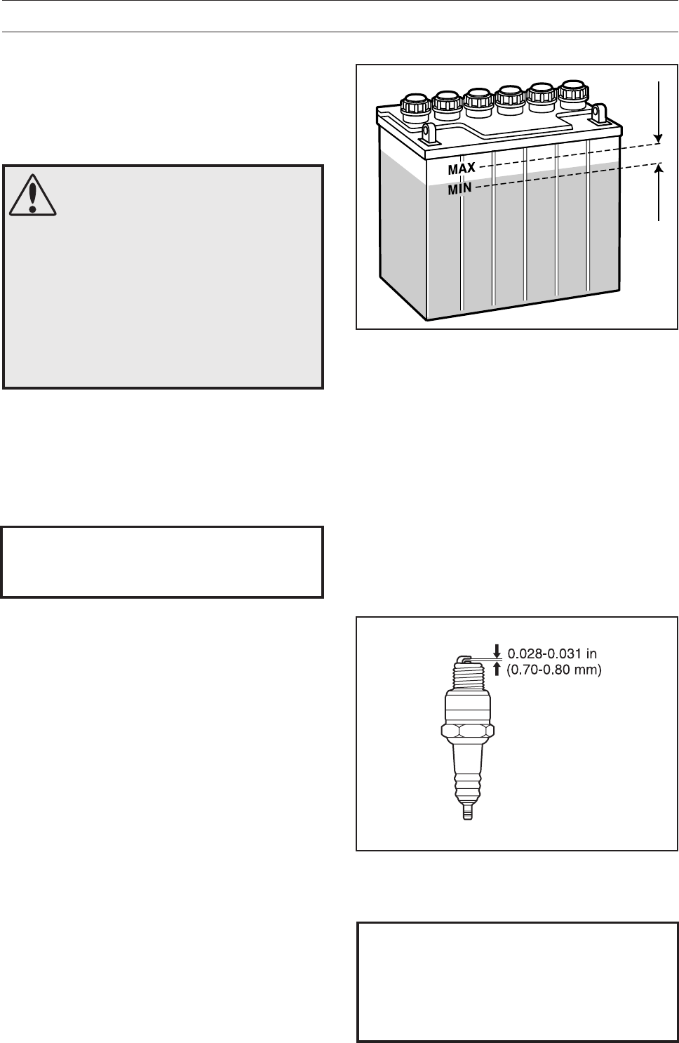
Checking the Acid Level in the Battery
Check that the acid level in the battery lies between
the markings. When refilling, only distilled water
may be used to fill the cells.
Ignition System
The engine is equipped with an electronic ignition
system. Only the spark plugs require maintenance.
For the recommended spark plug, see Technical
data.
IMPORTANT INFORMATION
Fitting the wrong spark plug type can
damage the engine.
Replacing the Spark Plug
1. Remove the ignition cable shoe and clean
around the spark plug.
2. Remove the spark plug with a 3/4" (19 mm)
spark plug socket wrench.
3. Check the spark plug. Replace the spark plug if
the electrodes are burned or if the insulation is
cracked or damaged. Clean the spark plug with
a wire brush if it is to be reused.
4. Measure the electrode gap with a gapping tool.
The gap should be 0.75 mm / 0.030". Adjust as
necessary by bending the side electrode.
5. Reinsert the spark plug, turning by hand to
avoid damaging the threads.
6. After the spark plug is seated, tighten it using a
spark plug wrench so that the washer is
compressed. A used spark plug should be
turned 1/8 of a turn from the seated position. A
new spark plug should be turned 1/4 a turn from
the seated position.
7. Replace the ignition cable shoe.
IMPORTANT INFORMATION
Inadequately tightened spark plugs can
cause overheating and damage the
engine. Tightening the spark plug too
much can damage the threads in the
cylinder head.
English – 33
8009-433
8009-434
8009-436
8009-435
8009-153
MAINTENANCE
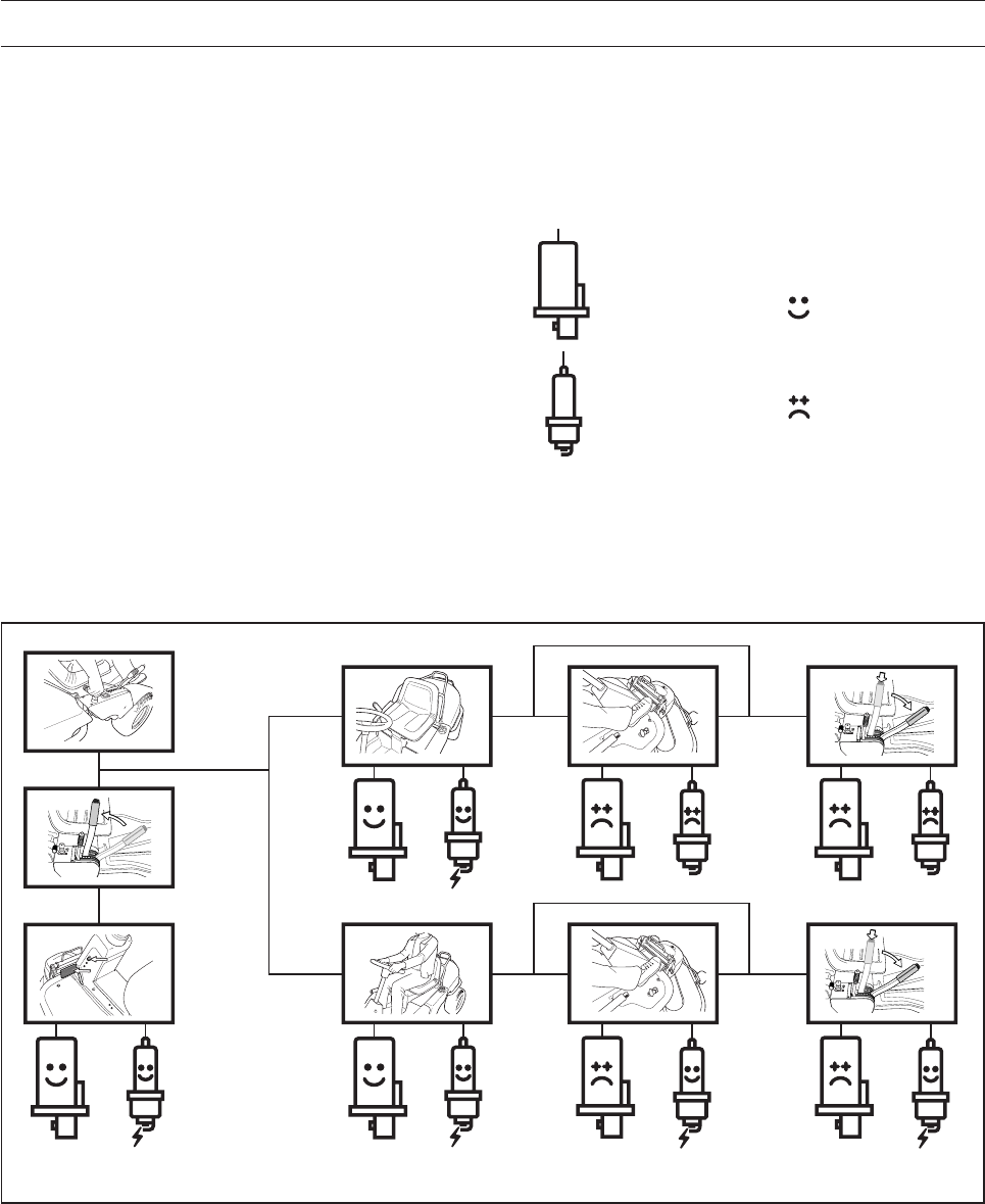
Checking the Safety System
The Rider is equipped with a safety system that
prevents starting or driving under the following
conditions.
The engine should only be possible to start when
the cutting unit is in its raised position and the
parking brake is applied.
The driver does not need to be seated in the
driver’s seat.
Make daily inspections to ensure that the safety
system works by attempting to start the engine
when one of the conditions is not met. Change the
conditions and try again.
Check that the engine stops if you temporarily
move out of the driver’s seat while the cutting unit is
lowered or the hydrostat pedals are not in the
neutral position.
Starter
Ignition system
Works
Does not work
34 – English
8009-511
MAINTENANCE
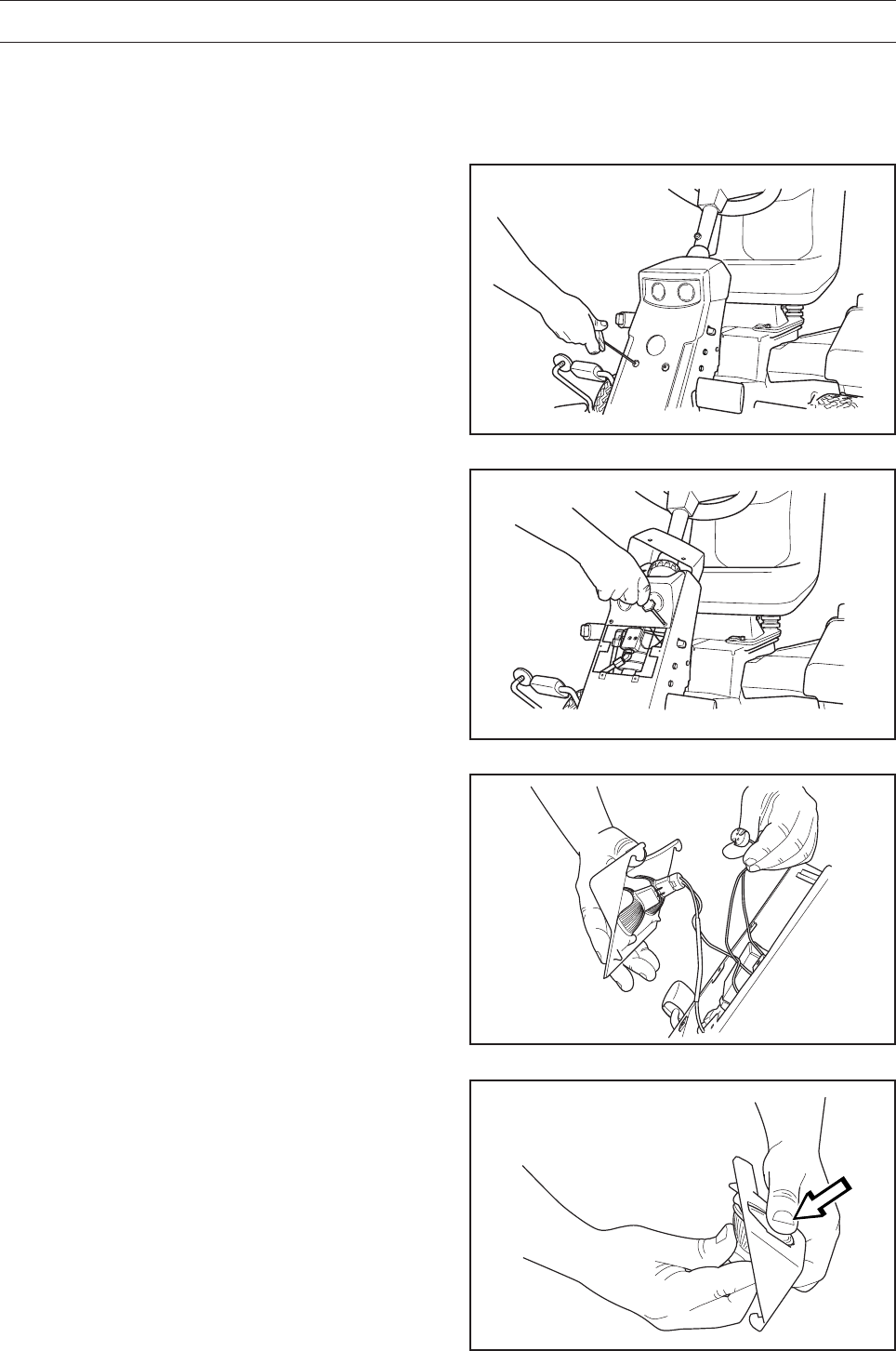
Replacing the Light Bulbs
For information about the bulb type, see ”Technical
Data”.
1. Unscrew the two screws holding the cover on
the power steering housing.
Lift up the cover and turn it around the steering
shaft.
8009-512
8009-513
8009-522
2. Unscrew the two screws holding the lamp
insert.
Lift out the lamp insert.
3. Disconnect the cables from the bulbs.
4. Lift out the bulbs from the insert.
5. Insert the new bulbs. Make sure you use your
thumb to support the front.
6. Refit the cables, lamp insert and the cover on
the power servo housing.
English – 35
6017-100
MAINTENANCE
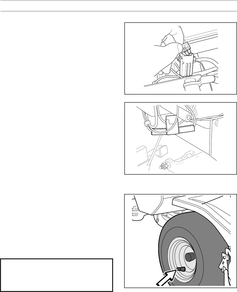
Checking the Tyre Pressures
The tyre pressure should be 60 kPa / 0.6 bar /
9 PSI on all wheels. The highest permitted
pressure is 100 kPa / 1.0 kp/cm2 / 14 PSI).
8009-370
Fuses
The main fuse is placed in a detachable holder
under the battery case’s cover, in front of the
battery.
Type: Flat pin, 15 A.
The fuse for the power outlet is placed under the
ignition switch, behind the side plate on the control
panel.
Type: Flat pin, 7.5 A.
Do not use any other type of fuse when replacing.
A blown fuse indicates that the mounting has burnt
off. Pull the fuse from the holder when replacing.
The fuse is there to protect the electrical system. If
it blows again shortly after replacement, it is due to
a short circuit, which must be fixed before the
machine can be put into operation again.
IMPORTANT INFORMATION
Different air pressure in the front tyres will
result in the blades mowing the grass at
different heights.
8009-586
36 – English
6008-209
MAINTENANCE
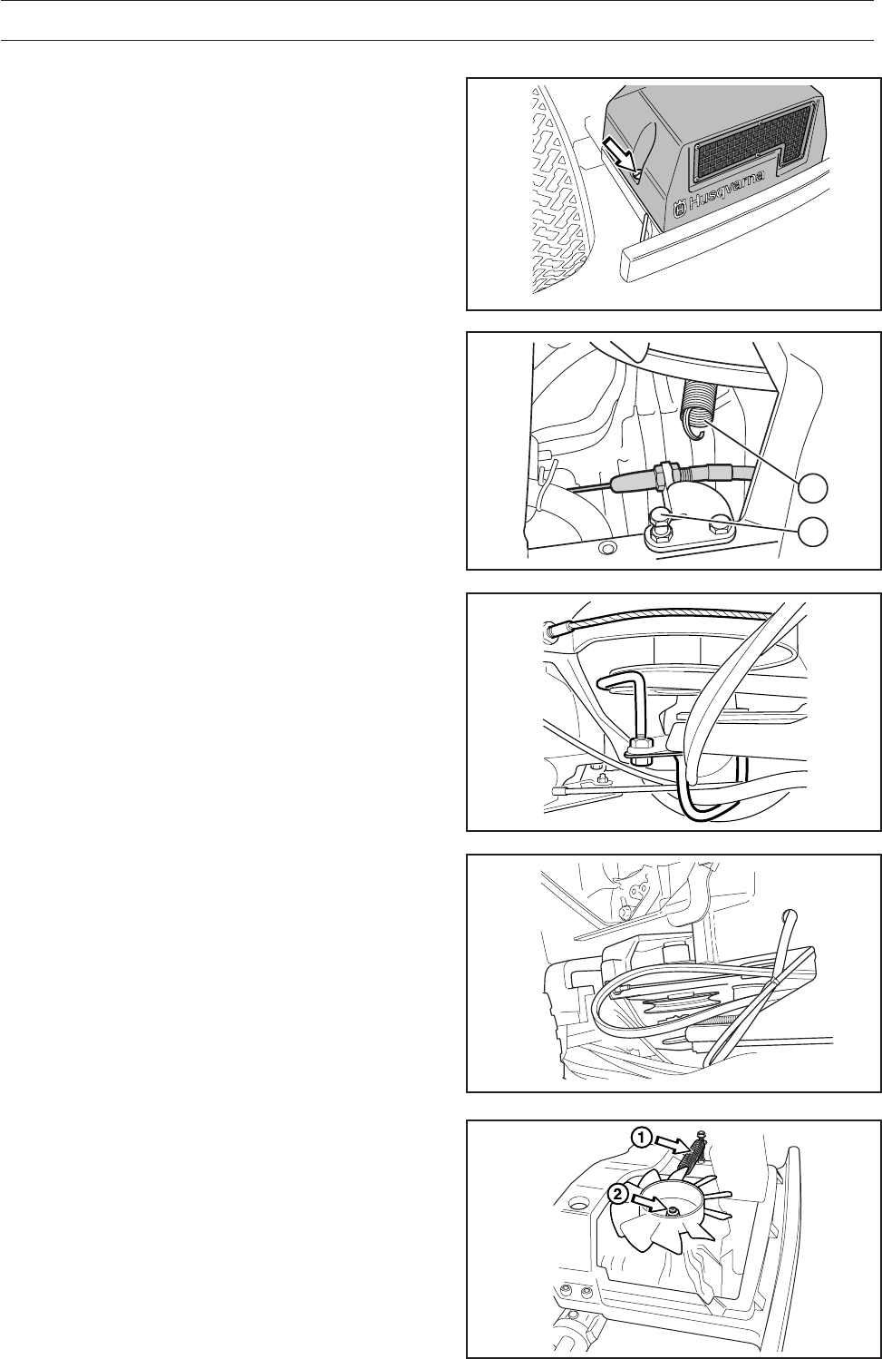
Replacing the Rear Drive Belt Pro 15
and Pro 18:
Removal
1. Remove the transmission cover.
2. Unhook the spring on the belt tensioner (A).
6020-005
B
A
3. Remove the hose clip on the middle and the belt
guide for the centre belt.
8009-364
4. Pull off the centre belt from the engine’s pulley
and pull out the rear section. A used belt can be
pulled downwards. When the belt is new, the
centre belt must be pulled off of its front pulley
whereupon it can be moved downwards from the
engine pulley so that the rear part can be pulled
out.
5. Remove the cooling fan (2).
6. Pull the belt off of the hydrostatic transmission’s
pulley.
8009-638
6012-036
English – 37
MAINTENANCE
7. Pull the pump belt off of the engine’s pulley and
move it under the engine belt pulleys.
8. Pull out the pump belt through the opening
under the pivot bearing and past the belt
tensioner’s disc.
Assembly
1. Pull the pump belt through the opening under
the pivot bearing and on the outside past
the belt tensioner’s disc.
2. Fit the pump belt on the engine’s pulley, move it
under the engine belt pulleys.
3. Fit the belt on the hydrostatic transmission’s
pulley.
4. Fit the cooling fan.
8009-640
8009-640
5. Tighten the cooling fan nut (2).
6. Check that the centre belt is fitted correctly on its
front pulley and fit the centre belt on the engine’s
pulley.
6012-036
7. Fit the hose clip on the middle and the belt guide
for the centre belt.
8009-364
8. Hook the spring on the belt tensioner (A) on
the screw (B).
6020-005
B
A
38 – English
MAINTENANCE
Replacing the Hydraulic Pump’s Drive
Belt
Pro 18 AWD
Removal
1. Remove the transmission cover.
8009-603
2. Unhook the spring on the belt tensioner.
3. Remove the belt guide for the centre belt.
8009-637
4. Pull off the centre belt from the engine’s pulley
and pull out the rear section. A used belt can be
pulled downwards. When the belt is new, the
centre belt must be pulled off of its front pulley
whereupon it can be moved downwards from the
engine pulley so that the rear part can be pulled
out.
8009-727
5. Remove the nut on the cooling fan. Counter hold
using a punch in one of the holes on the
underside of the fan when the nut is loosened.
8009-638
8009-726
English – 39
MAINTENANCE
6. Remove the clamp on the hydraulic pipes,
located under the fan. Loosen the pipe
connections from the pump slightly, bend the
hydraulic pipes down and pull the cooling fan out
backwards.
7. Pull the belt off of the pump’s pulley.
8009-641
8. Pull the pump belt off of the engine’s pulley and
move it under the engine belt pulleys.
9. Pull out the pump belt through the opening
under the pivot bearing and past the belt
tensioner’s disc.
Assembly
10. Pull the pump belt through the opening under
the pivot bearing and on the outside past the
belt tensioner’s disc.
11. Fit the pump belt on the engine’s pulley, move it
under the engine belt pulleys.
8009-640
12. Fit the belt on the pump’s pulley.
13. Fit the cooling fan.
8009-640
14.Tighten the cooling fan nut. Counter hold using a
punch in one of the holes on the underside of
the fan when the nut is tightened.
15.Refit the clamp on the hydraulic pipes, located
under the fan. Tighten the pipe connections on
the pump.
16.Check that the centre belt is fitted correctly on its
front pulley and fit the centre belt on the engine’s
pulley.
8009-641
8009-726
40 – English
MAINTENANCE
17. Fit the belt guide for the centre belt.
8009-727
18. Hook the spring on the belt tensioner.
8009-637
Replacing the Centre Belt
1. Remove the hose clip in the middle (Pro 15,
Pro 18) and the rear belt guide for the centre
belt (all machines).
2. Remove the centre belt and fit a new belt.
8009-364
3. Fit and adjust the belt guide with the lower belt
on the engine belt pulley. On Pro 15, Pro 18 also
fit the hose clip in the middle as in the figure
above.
4. Check and adjust the belt tensioner. This is
especially important when fitting a new belt,
since stretching of the old belt may have been
compensated for by changing the setting of the
belt adjuster.
8009-727
8009-401
English – 41
MAINTENANCE
Replacing the Front Belt Pro 15, Pro 18
Dismantling
The entire belt is removed according to the
following when a snow blade is to be attached to
the machine.
1. Remove the cutting unit.
2. Loosen the belt guides and the support pully.
3. Loosen the wheel on the belt tensioner.
4. Ease off the belt from the middle pulley and
remove the belt.
Assembly
1. Fit the belt on the centre pulley.
2. Move the belt into position and fit the belt on the
belt tensioner.
3. Position the belt on the support pulley and
tighten the belt guide.
4. Fit the cutting equipment.
8009-227
8
9
Replacing the Front Belt Pro 18 AWD
Dismantling
The entire belt is removed according to the following
when a snow blade is to be attached to the machine.
1. Put the cutting unit in the service position.
2. Pull the centre belt off of the centre pulley. The
belt becomes slack when the cutting unit is lifted.
3. Take off the front belt from the centre pulley and
remove the belt. 6017-227
Assembly
1. Position the belt from the front. Pull the belt on
the outside of the runner pulley and on the
inside of the adjuster pulley.
8009-684
8009-596
42 – English
2. Fit the centre belt in position on the centre
pulley.
MAINTENANCE
3. Reset the cutting unit in the mowing position.
Make sure that the tongue (3) mates with the
loop on the underside of the machine.
8009-695
4. The belt is fitted on the cutting unit’s drive pulley
once the unit has been pushed back into its rear
position.
8009-595
8009-122

English – 43
1
2
3
6017-159
8009-595
8009-699
6017-120
8009-596
MAINTENANCE
Fitting the Cutting Unit
WARNING!
Observe caution to avoid
trapping your hand.
5. Press down the frame and secure with the split
pin. Fit the drive belt around the unit’s drive
pulley.
6. Hook in the height adjustment stay.
WARNING!
Wear protective glasses when
assembling the cutting unit. The
spring that tensions the belt can
fly off and cause
personal injury.
1. Place the Rider on a flat surface and apply the
parking brake. Check that the lever for setting
the cutting height is in the lowest position.
Ensure the anti-scalp roller is fitted on the
cutting unit (1).
2. Grasp the handle on the front of cutting unit’s
frame (2) and push the unit in under the Rider.
Make sure the tongue (3) on the unit mates
correctly.
3. Fit the screw and secure with a locking pin.
4. Place the belt over the runner pulley and behind
the adjuster pulley.
44 – English
MAINTENANCE
Removing the Cutting Unit
1. Follow ”The Cutting Unit’s Service Position”,
points 1-9 to put the cutting unit in the service
position.
2. Remove the bolt (3) and lift off the cutting unit.
WARNING!
Wear protective glasses when
dismantling the cutting unit. The
springs that tension the belt can
fly off and cause personal injury.
7. Fit the anti-scalp rollers in position
8. Fit the front cover.
9. Secure the springs on the adjuster pulley.
There are two designs, see the figures.
8009-439
8009-440
8009-674
8009-598
English – 45
MAINTENANCE
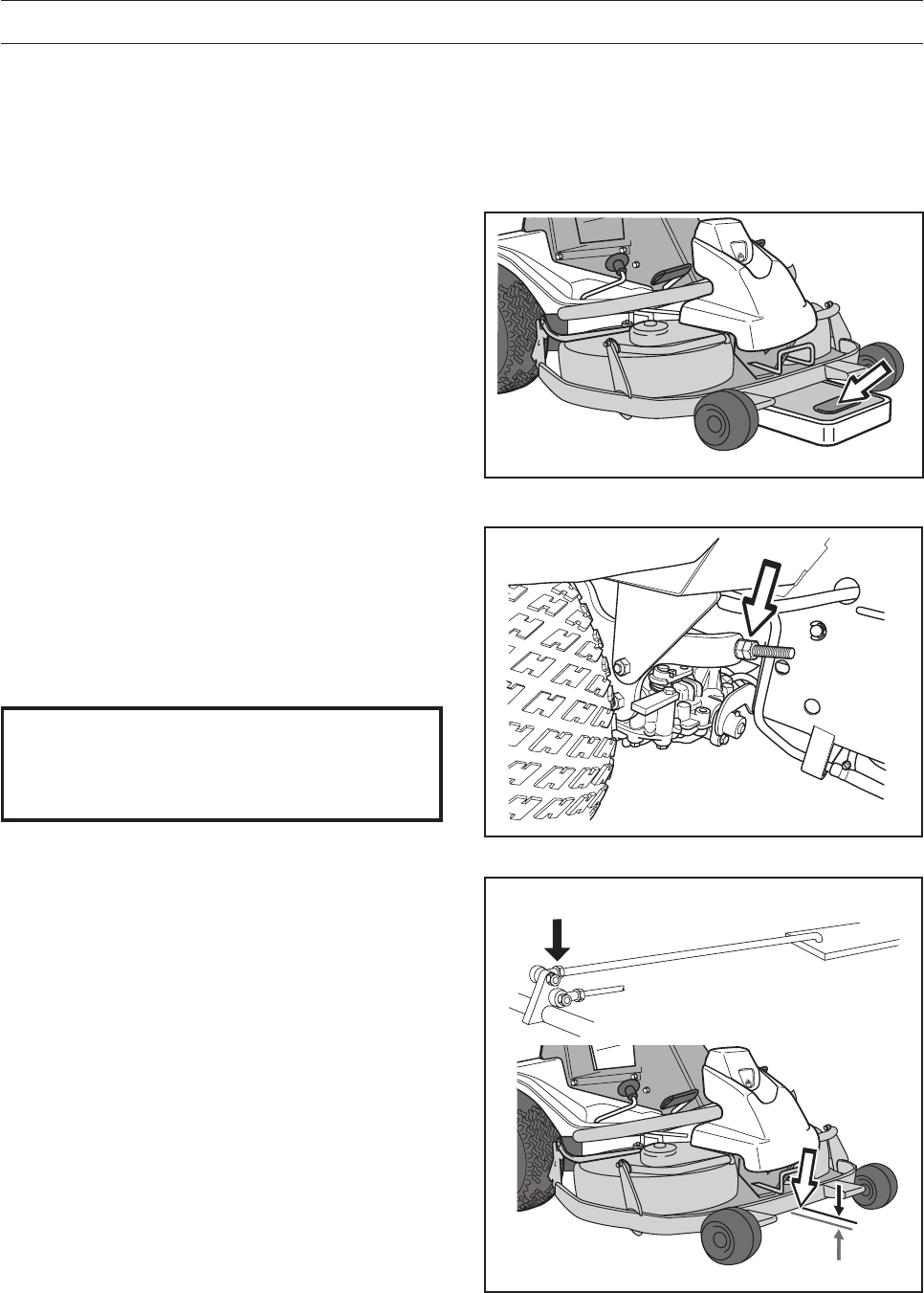
Checking and Adjusting the Cutting
Unit’s Ground Pressure
In order to achieve the best mowing result the
cutting unit should follow the ground without
touching it too heavily. The pressure is adjusted
using a screw on each side of the Rider.
1. Check the air pressure in the tyres 60 kPa /
0.6 bar / 9 PSI.
2. Place the Rider on a flat surface.
3. Put the lifting lever in the mowing position.
4. Place a set of bathroom scales under the
cutting unit’s frame (on the front edge) so that
the unit rests on the scales. If necessary a
block can be placed between the frame and the
scales so that the anti-scalp rollers do not
support any weight.
5. Adjust the cutting unit’s ground pressure by
screwing the adjuster screws, which are located
behind the front wheels on both sides, in or out.
The ground pressure should be between 12
and 15 kg (26.5-33 lb).
8009-028
8009-564
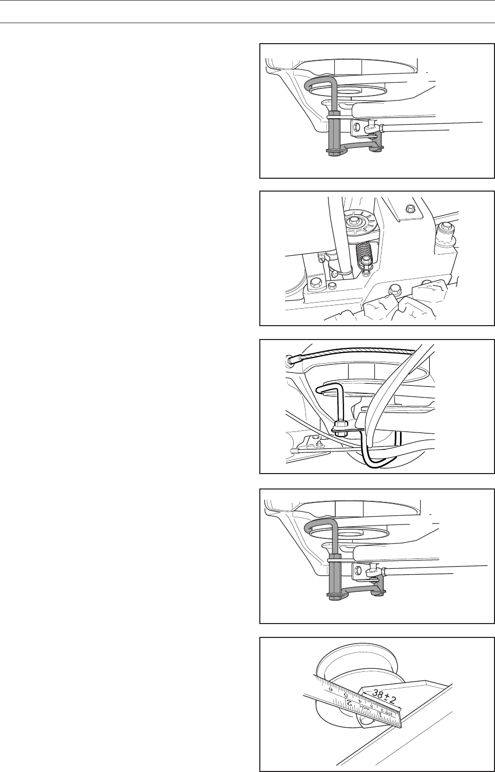
Cutting Height
1. Place the Rider on a flat surface.
2. Loosen the nut on the height adjustment strut.
3. Measure the distance between the ground and
cutting unit’s edge at the front of the cover. The
cutting unit should have a slight slant, with the
rear edge 2-4 mm (1/8") higher than the front
edge.
The distance between the front edge and the
ground should be:
• 40 mm for Combi 94 and Combi 103
• 35 mm for Combi 112.
4. Tighten the nut.
5. Check that the parallelism has not changed. If
so, the parallelism must be readjusted.
6. Check and if necessary adjust the cutting unit’s
ground pressure.
7. Fit the front cover.
IMPORTANT INFORMATION
When changing the cutting unit, you must
readjust the parallelism and cutting height.
6017-216
8009-597
46 – English
MAINTENANCE
Adjusting the Parallelism of the Cutting
Unit
1. Remove the front cover and the right-hand wing
cover.
2. Loosen the nuts on the parallel strut.
3 Screw out (extend) the strut to raise the rear
edge of the cover.
Screw in (shorten) the strut to lower the rear
edge of the cover.
4. Tighten the nuts after adjustment.
5. The parallelism of the cutting unit should be
checked again after the adjustment has been
made.
6. Fit the right-hand wing cover and the front
cover.
Checking the Parallelism of the Cutting
Unit
Check the cutting unit’s parallelism as follows:
1. Check the air pressure in the tyres
60 kPa / 0.6 bar / 9 PSI.
2. Place the Rider on a flat surface.
3. Put the lifting lever in the mowing position.
4. Measure the distance between the ground and
the front and back edges of the unit’s cover.
The cutting unit should have a slight slant, with
the rear edge 2–4 mm (1/8") higher than the
front edge.
6017-018
6017-217
English – 47
MAINTENANCE
WARNING!
Protect your hands with gloves
when working with the blades.
8009-287
6012-080
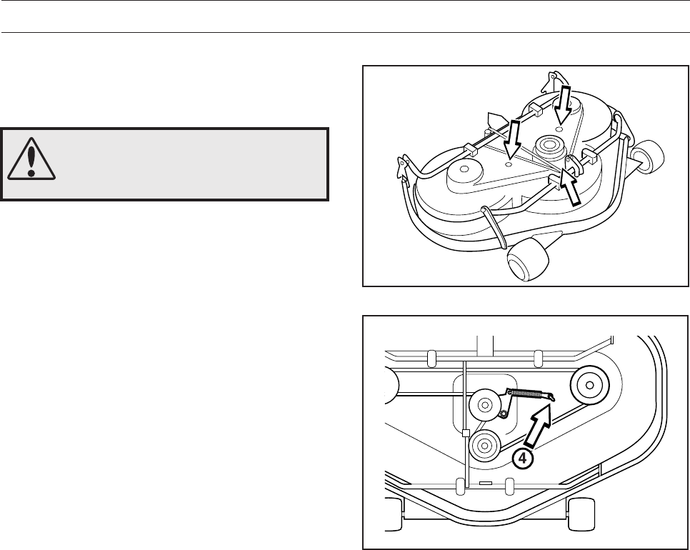
On cutting units with ”collision-proof” blades, the
blades are driven by a V-belt. Do as follows to
replace the V-belt:
1. Dismantle the cutting unit.
2. Loosen the bolt to the parallel strut and the two
screws on the cover. Lift off the cutting unit
cover.
3. Loosen the spring (4) that tensions the V-belt
and pull the belt off.
Attach a new belt in the reverse order.
Changing the Belt on the Combi 94 and
Combi 112
48 – English
MAINTENANCE
The Cutting Unit’s Service Position
In order to provide good accessibility for cleaning,
repair and servicing, the unit can be set in the
service position. The service position means that
the unit is raised and locked in the vertical position.
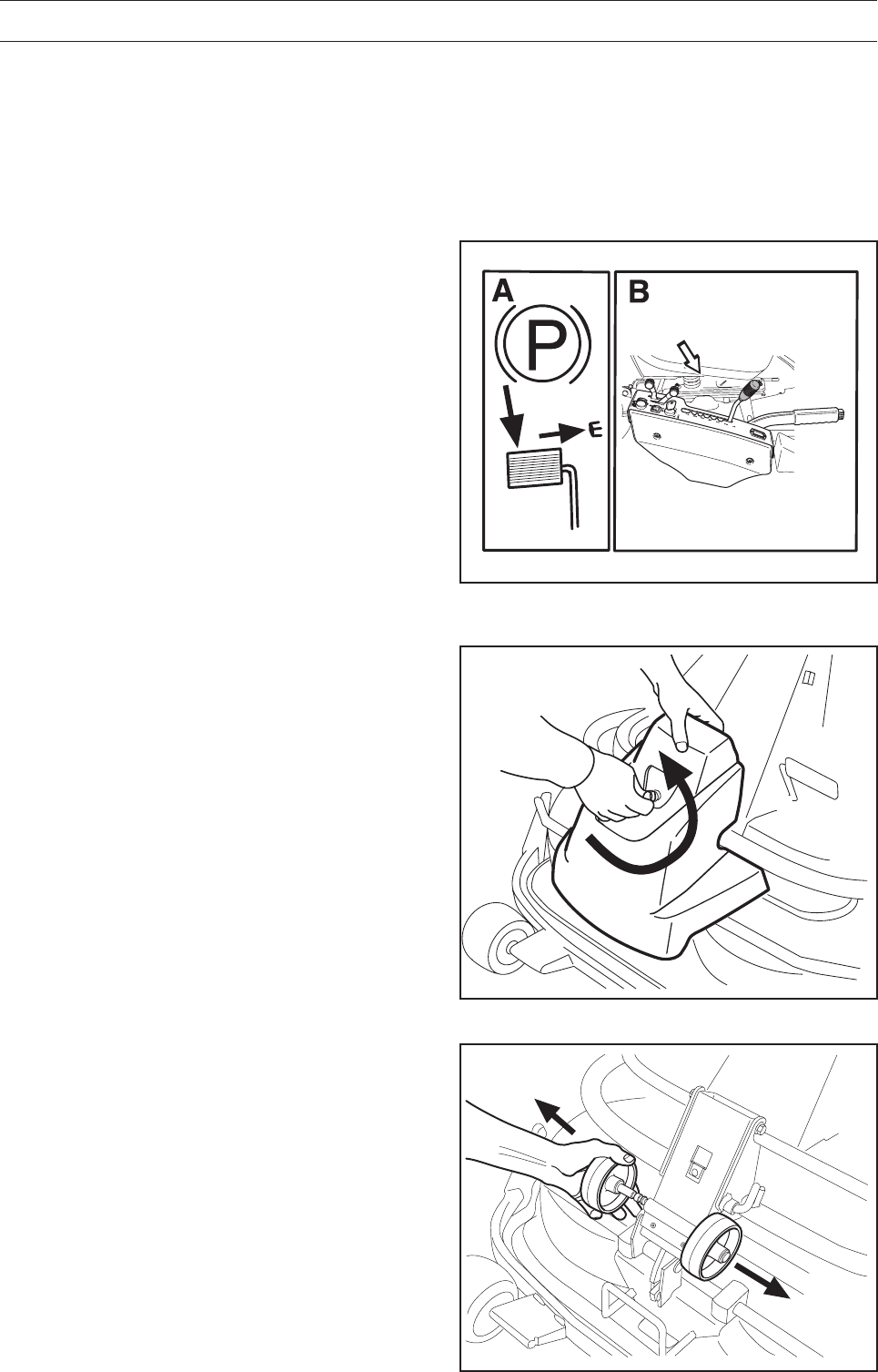
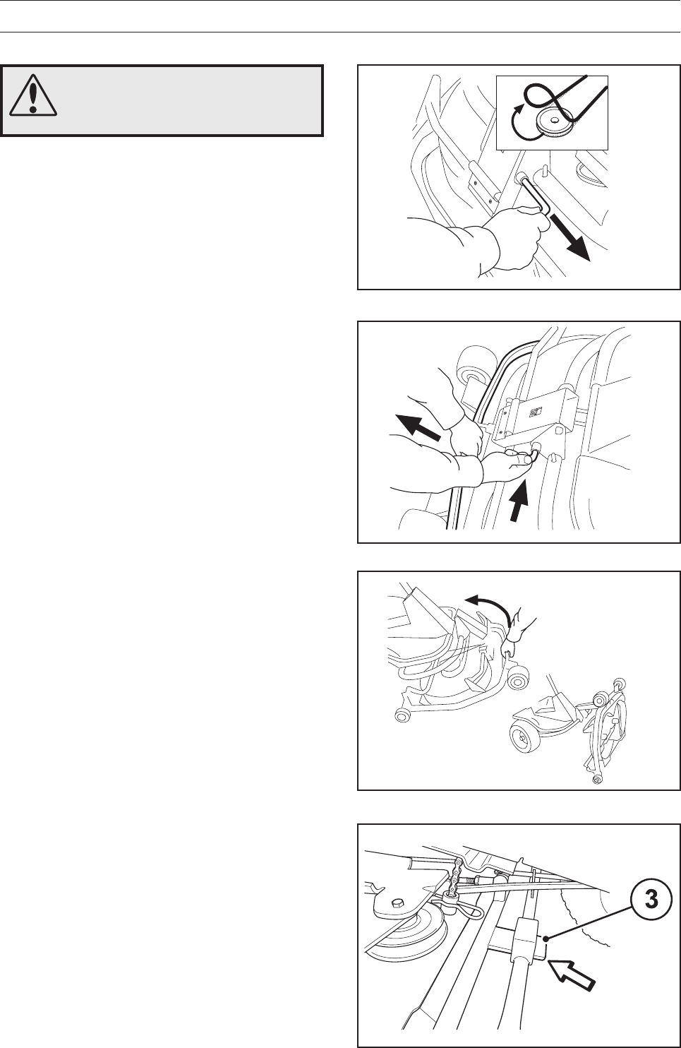
Placing in the Service Position
1. Place the machine so it is flat. Activate the
parking brake (A). Set the cutting deck to the
lowest cutting height and lower the cutting unit
(B).
3. Loosen the two anti-scalp rollers, located under
the front cover.
2. Remove the front cover by loosening the split
pin. (Complete instructions for the service
position can be found on the inside of the front
cover).
8009-587
6017-219
6017-220
English – 49
MAINTENANCE
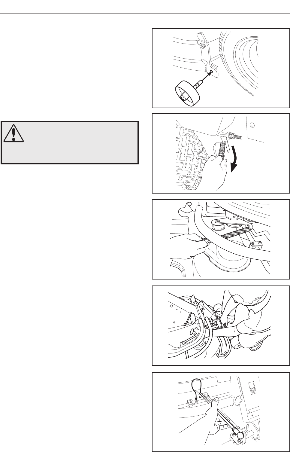
7. Secure the stay in the holder.
4. Fit the two anti-scalp rollers on each side of the
cutting unit’s rear section.
5. Loosen the spring on the drive belt’s belt idler.
There are two designs, see the figures.
6. Put your foot on the front edge of the cutting
unit next to the wheel and lift the cutting unit’s
front edge to make it easier to loosen the height
adjustment stay.
WARNING!
Wear protective glasses when
dismantling the cutting unit. The
springs that tension the belt can
fly off and cause personal injury.
6017-221
6017-222
8009-122
6017-223
8009-598
50 – English
MAINTENANCE
8. Lift off the drive belt (1). Now pull out the split
pin (2).
9. Pull the frame forwards and refit the pin.
10. Grasp the cutting unit’s front edge, pull out and
lift up into the service position.
If the cylindrical bolt, which is now holding the
cutting unit is removed, the cutting unit can be
lifted off.
Releasing the Service Position
To leave the service position, reverse the
procedures set out in ”Placing in the Service
Position”. Make sure that the cutting unit’s tongue
(3) enters the loop correctly on the underside of the
machine.
WARNING!
Observe caution to avoid trapping
your hand.
2
1
6017-225
6017-226
6017-227
8009-595
English – 51
8009-288
8009-288
MAINTENANCE
IMPORTANT INFORMATION
Replacement or sharpening of the blades
should be carried out by an authorised
service representative.
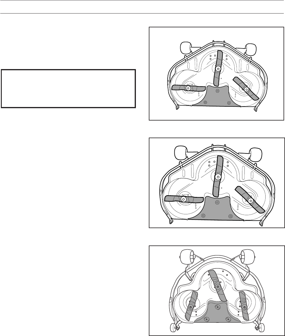
Inspecting the Blades
It is important that the blades are undamaged and
well-ground to give the best mowing result.
Check that the blades’ mounting bolts are tightened.
The blades should be balanced after sharpening.
Damaged blades should be replaced when hitting
obstacles that result in a breakdown. Let the
servicing dealer judge whether the blade can be
repaired/ground or must be discarded.
Combi 103
Combi 112
8009-601
Combi 94
52 – English
MAINTENANCE
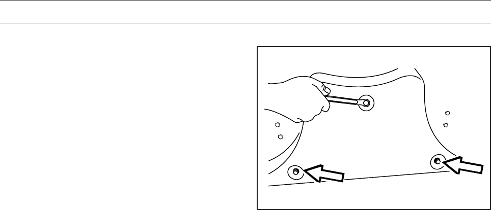
Removing the BioClip Plug (Combi)
To change a Combi unit from the BioClip function to
a cutting unit with rear ejection, remove the BioClip
plug, which is located under the unit, attached with
three screws.
1. Put the unit in the service position, see ”Placing
in the Service Position”.
2. Remove the three screws holding the BioClip
plug, and remove the plug.
3. Tip: Fit three full-thread screws M8x15 mm in
the screw holes to protect the threads.
4. Return the unit to the normal position.
Fit the BioClip plug in the reverse order.
Removal of BioClip plug
8009-289
English – 53
LUBRICATION
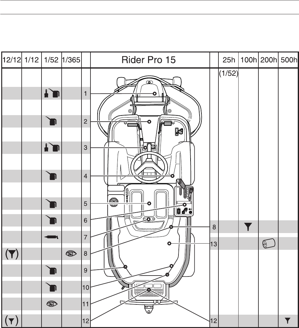
Lubrication Chart Pro 15
8009-589
The position numbers for the lubrication points refer to the lubrication instructions on the following pages.
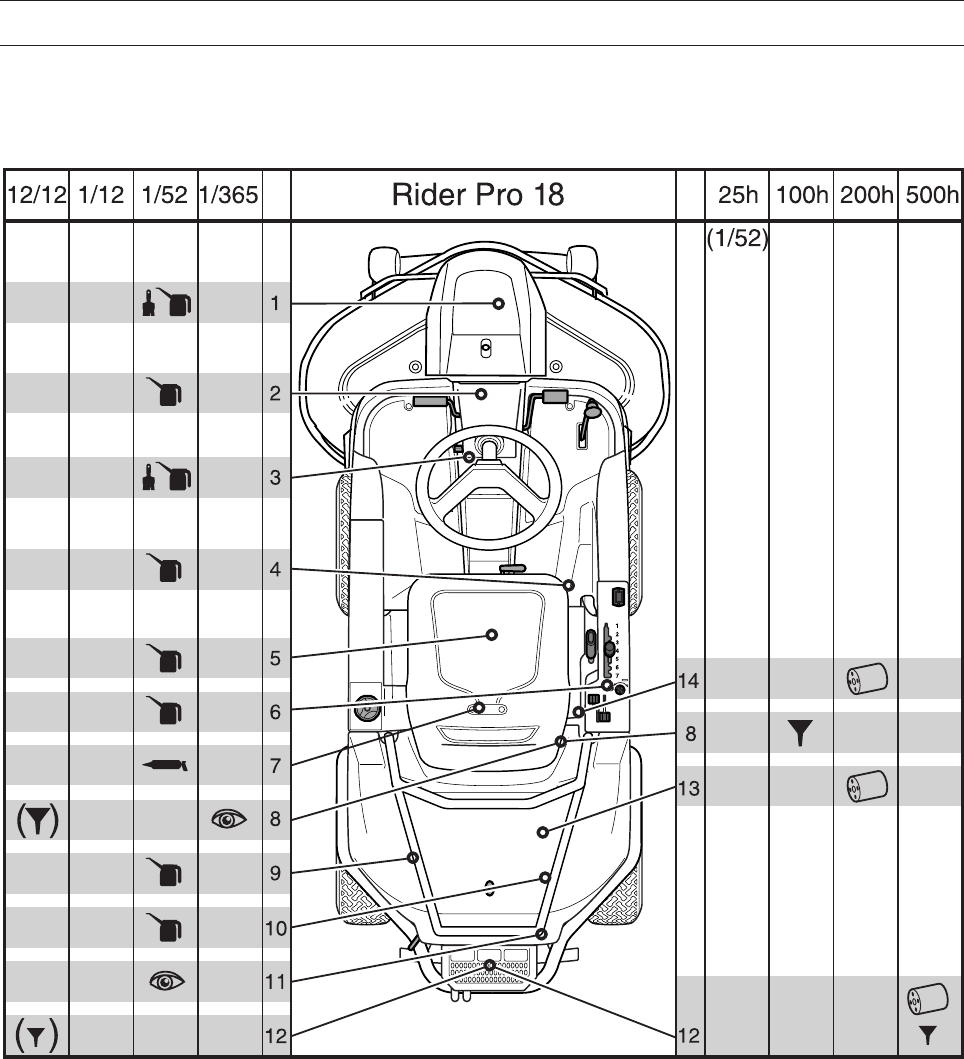
54 – English
LUBRICATION
Lubrication Chart Pro 18
8009-504
The position numbers for the lubrication points refer to the lubrication instructions on the following pages.
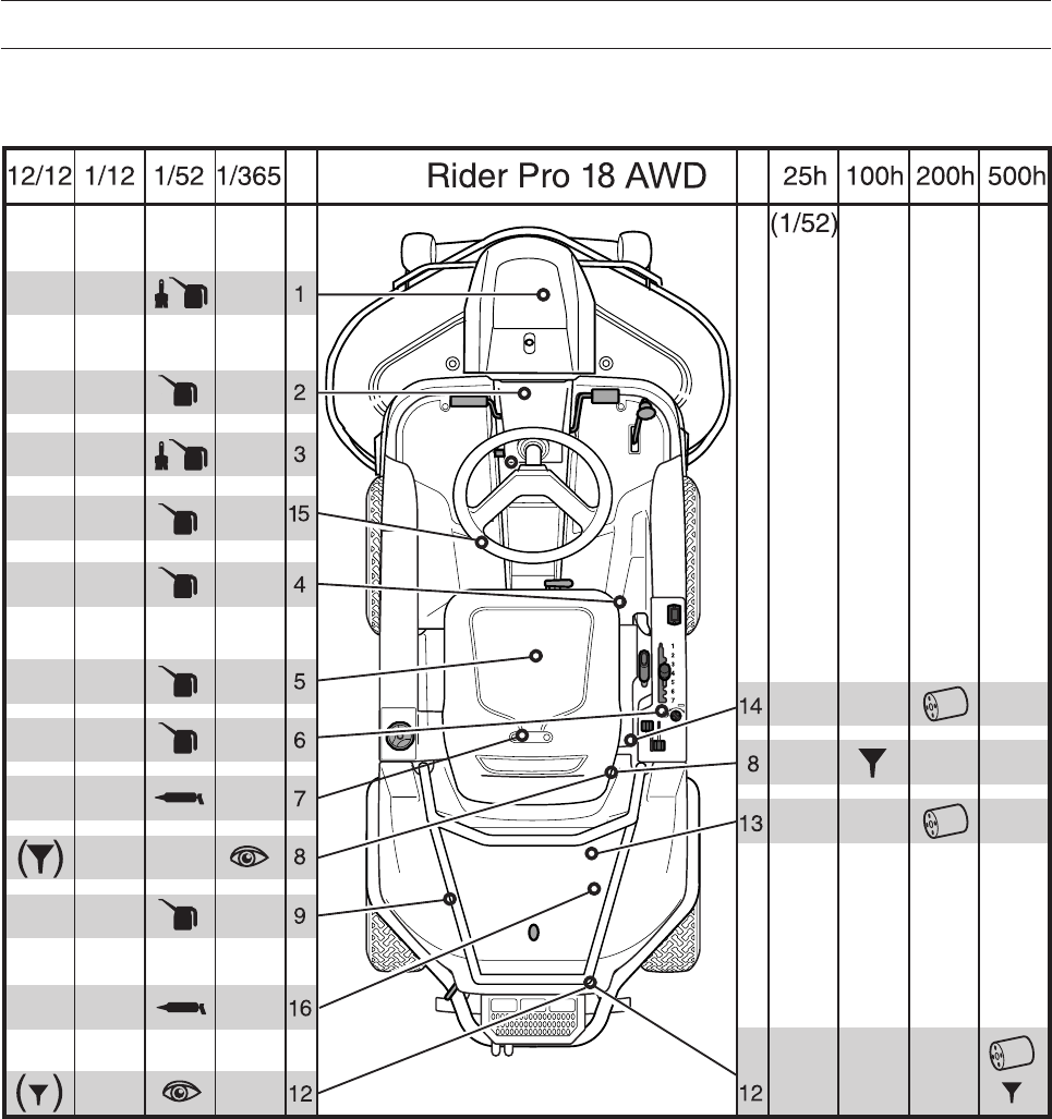
English – 55
LUBRICATION
Lubrication Chart Pro 18 AWD
8009-681
The position numbers for the lubrication points refer to the lubrication instructions on the following pages.
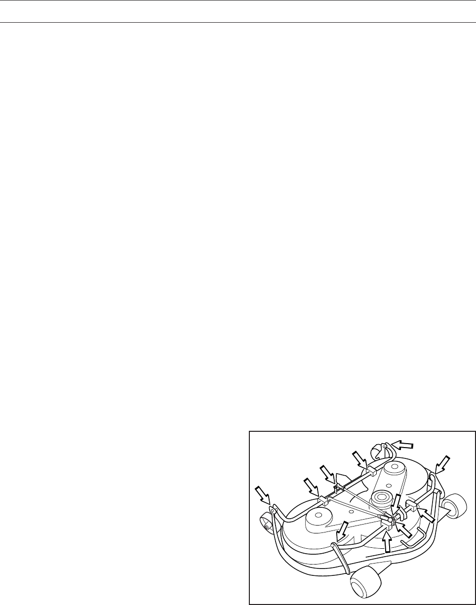
56 – English
General
Remove the ignition key to prevent unintentional movements during lubrication.
When lubricating with an oilcan, it ought to be filled with engine oil.
When lubricating with grease, unless otherwise stated, grease 503 98 96-01 or another chassis or ball
bearing grease offering good corrosion protection shall be used.
With daily use, the Rider should be lubricated twice weekly.
Wipe away excess grease after lubrication.
It is important to avoid getting lubricant on the belts or the drive surfaces on the belt pulleys. Should this
happen, attempt to clean them with spirits. If the belt continues to slip after cleaning with spirits, it must be
replaced. Petrol or other petroleum products must not be used to clean belts.
Lubricating the Cables
Grease both ends of the cables and move the controls to end stop positions when lubricating. Re-attach the
rubber covers on the cables after lubrication. Cables with sheaths will jam if they are not lubricated regularly.
Binding in a cable may cause malfunction such as partial braking.
If a cable binds, remove the cable and hang it vertically. Lubricate it with thin engine oil until the oil begins to
escape from the bottom. Tip: Fill a small plastic bag with oil and tape it so that it seals against the casing and
allow the cable to hang vertically from the bag overnight. If you do not succeed in lubricating the cable, it
must be replaced.
LUBRICATION
Lubrication Instructions According to
the Schedule
1. Cutting Unit
Remove the nose cover.
Lubricate using an oilcan:
- Joints and bearings
8009-154
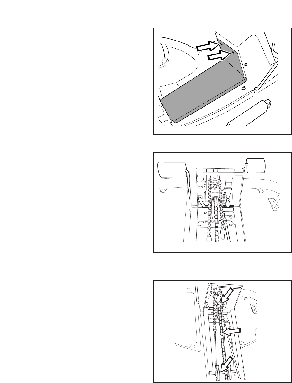
English – 57
2. Pedal Mechanism in Frame Tunnel
Lubricate the pedal mechanism in the frame tunnel.
Remove the cover of the frame tunnel by loosening
the screws (two on the steering servo housing).
Work the pedals and lubricate the moving parts with
an oilcan.
Lubricate the cables to the brake and drive pedals
with an oilcan.
Lubricate the point ”Chains in the Frame Tunnel”
before replacing the cover to the frame tunnel.
LUBRICATION
8009-345
8009-505
6020-022
3. Chains in the Frame Tunnel
Remove the cover from the frame tunnel, see point 2.
Lubricate the chains in the frame tunnel with an
oilcan or chain lubricant spray for motorcycles.
Lubricate the steering cable pulley axle with
grease. Move the pulleys to one side and brush
grease on the axle.
Replace the cover on the frame tunnel.
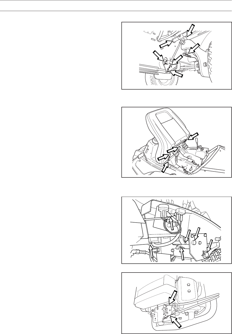
58 – English
8009-155
4. Three-Point Link and Joints
Lubricate the three-point link and joints for cutting
height setting stay behind the right, front wheel.
Lubricate using an oilcan.
LUBRICATION
5. Driver’s Seat
Tilt the seat back.
Lubricate the lengthways adjustment mechanism
with the oilcan.
Lubricate the lengthways adjustment runners with
the oilcan.
8009-157
8009-506
6. Throttle and Choke Cables, Lever
Bearings
Remove the right side cover of the lever housing
and open the engine cover. Lubricate the cables’
free ends with the oil can, even those by the
engine. Move the controls to the end points and
lubricate again.
Lubricate the joints, catches, and bearings for the
cutting unit’s control levers with an oilcan.
Replace the lever housing’s side cover.
8009-521
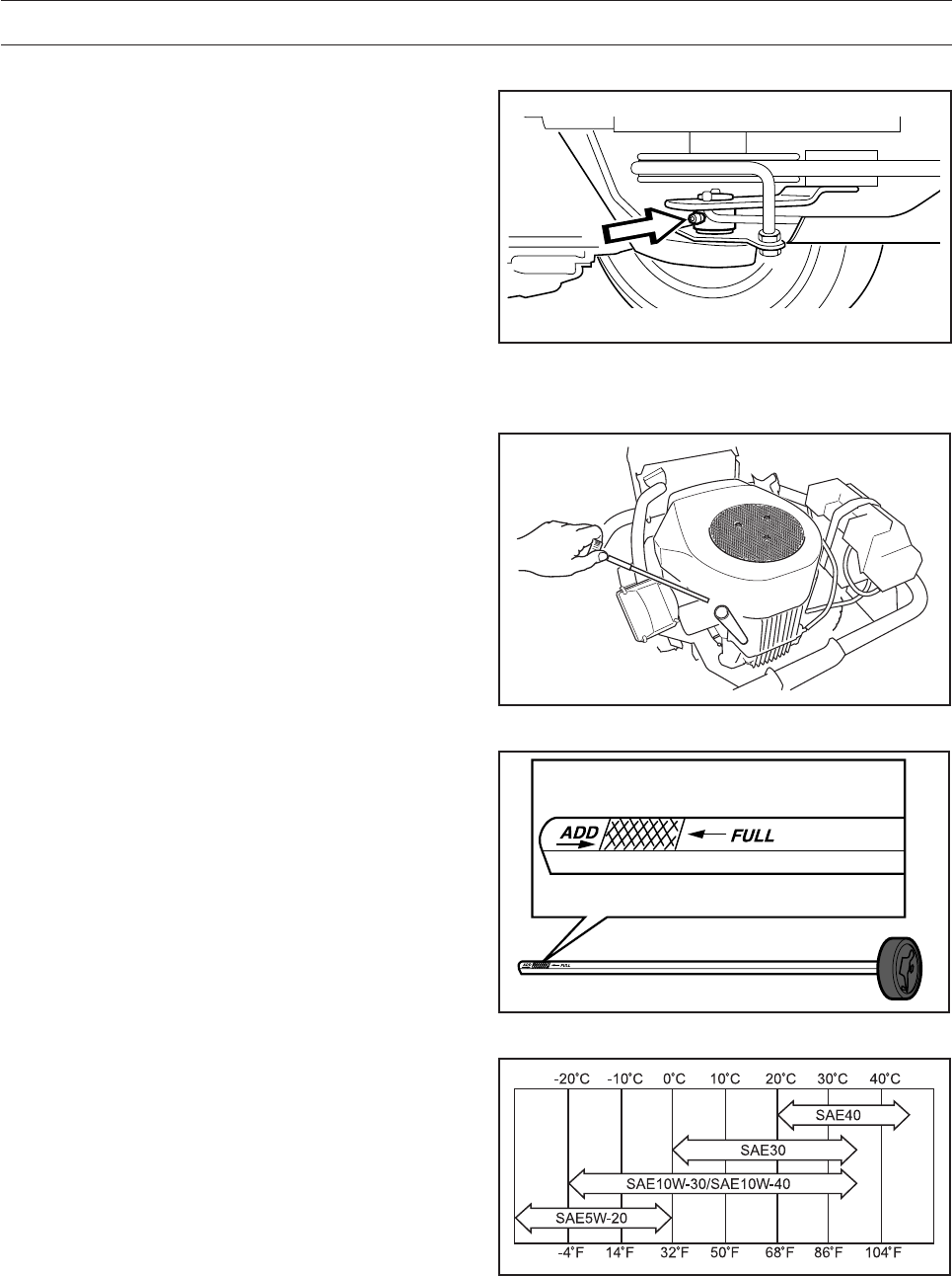
English – 59
7. Belt Tensioner
Lubricate using a grease gun, 1 nipple from the
right-hand side under the engine’s lower belt pulley,
until grease is forced out.
Use only good quality molybdenum disulphide
grease.
Grease from well-known brand names
(petrochemical companies, etc.) usually maintains
a good quality.
LUBRICATION
6008-232
8009-158
8009-159
8009-140
8. Engine Oil
Check the oil level in the engine when the Rider
stands horizontal with the engine switched off.
Open the engine cover.
Remove the dipstick and wipe it clean. Now insert
the dipstick again, without tightening it.
Take the dipstick out again and read the oil level.
The oil is topped up through the hole the dipstick
sits in.
Use engine oil SAE 30, SAE 10W/30 or 10W/40,
class SF-SJ (above 0 °C/+32 °F).
SAE 40 can be used above +20 °C/+68 °F.
Use engine oil SAE 5W/20, class SF-SJ
(below 0 °C/+32 °F).
Fill the oil slowly. Tighten the dipstick correctly
before starting the engine. Start and run the engine
at idling speed for approx. 30 seconds. Turn off the
engine. Wait 30 seconds and check oil level. If
necessary fill so that the oil comes up to the ”FULL”
mark on the dipstick.
The engine holds 1.5 litres of oil excluding the filter
and 1.7 litres including the filter.
The oil level should be between the markings on
the dipstick. If the level is approaching the ”ADD”
mark, top up the oil to the ”FULL” mark on the
dipstick.
Never fill above the ”FULL” mark.
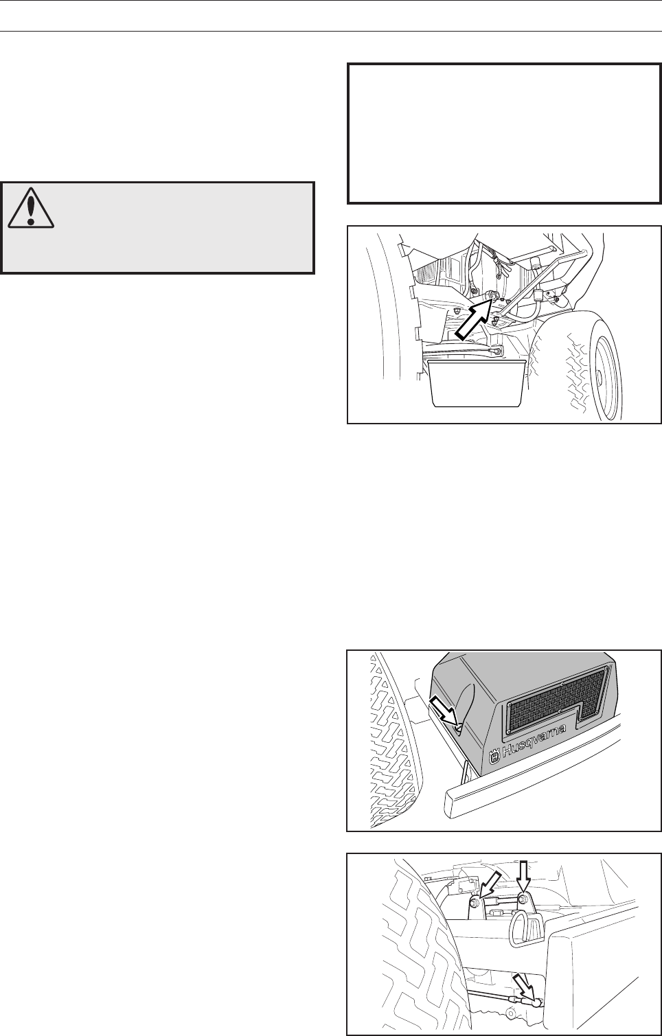
60 – English
8009-529
LUBRICATION
Changing the Engine Oil
The engine oil should be changed the first time
after 8 hours running time. It should then be
changed after every 100 hours of running time.
When operating with a heavy load or at high
ambient temperatures, replace every 50 hours.
1. Open the engine cover.
2. Place a container underneath the engine’s left
oil drain plug.
3. Remove the dipstick. Remove the drain plug
from the engine’s left side.
4. Let the oil run out into the container.
5. Then replace the oil drain plug and tighten it.
6. Replace the oil filter if necessary.
7. Fill with oil up to the FULL mark on the dipstick.
Use engine oil as set out above.
8. Run the engine warm, then check that there is
no leakage from the oil plug.
9. Check the oil level. Top up if necessary.
WARNING!
Engine oil can be very hot if it is
drained directly after stopping
the engine. Allow the engine to
cool somewhat first.
IMPORTANT INFORMATION
Used engine oil is a health hazard and must
not be disposed of on the ground or in
nature; it should always be disposed of at a
workshop or appropriate disposal location.
Avoid skin contact; wash with soap and
water in case of spills.
6008-209
6020-024
9. Hydrostatic Cable with Linkage
Remove the transmission cover, two screws.
Lubricate the joints and bearings on the left side
with an oilcan.
Remove the rubber casing and lubricate the
hydrostatic transmission cable with an oil can.
Press the pedal a few times and lubricate again.
Replace the rubber cover.
Replace the transmission cover.
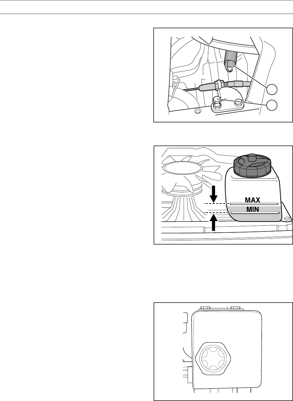
English – 61
LUBRICATION
10. Parking Brake Cable Pro 15, Pro 18
Remove the transmission cover, see ”Gear Lever”.
Unhook the spring (A) from the screw (B) if required
(not AWD).
Remove the cable’s rubber casing when lubricating.
Lubricate the cable with an oilcan, press the brake
pedal a few times and lubricate again.
Replace the spring (A) and the transmission cover.
11. Transmission Oil Level Pro 15, Pro 18
1. Check the oil level in the transmission by
looking through the air intake mesh. The oil
level shall be between the MIN and MAX
markings on the oil container when at +20 °C.
If the oil needs to be filled, you must first
remove the transmission cover.
2. Unscrew the oil container’s cover and fill with
SAE 10W/30 engine oil, class SF–CC, until the
oil level reaches the MAX mark. Then screw the
oil container’s cap into place and attach the
transmission cover.
The oil should be changed by an authorised service
workshop, and is described in the Workshop
Manual.
Filter replacement on Pro 18 is done at the same
time as changing the oil.
B
A
6008-210
6020-005
12. Hydraulic System and Transmission
Oil level Pro 18 AWD
1. Remove the transmission cover.
2. Check the level, it should be visible in the sight
glass at 20 °C when the machine stands flat.
3. Unscrew the oil container’s cover and fill with
SAE 10W/40 engine oil, class SF-CC, until the
oil level is visible in the top of the sight glass.
Then screw the oil container’s cap into place
and attach the transmission cover.
The oil should be changed by an authorised service
workshop, and is described in the Workshop
Manual.
The filter is replaced at the same time as changing
the oil.
Work on the system entails particular demands on
cleanliness and the system must be vented before
the machine is used.
8009-702
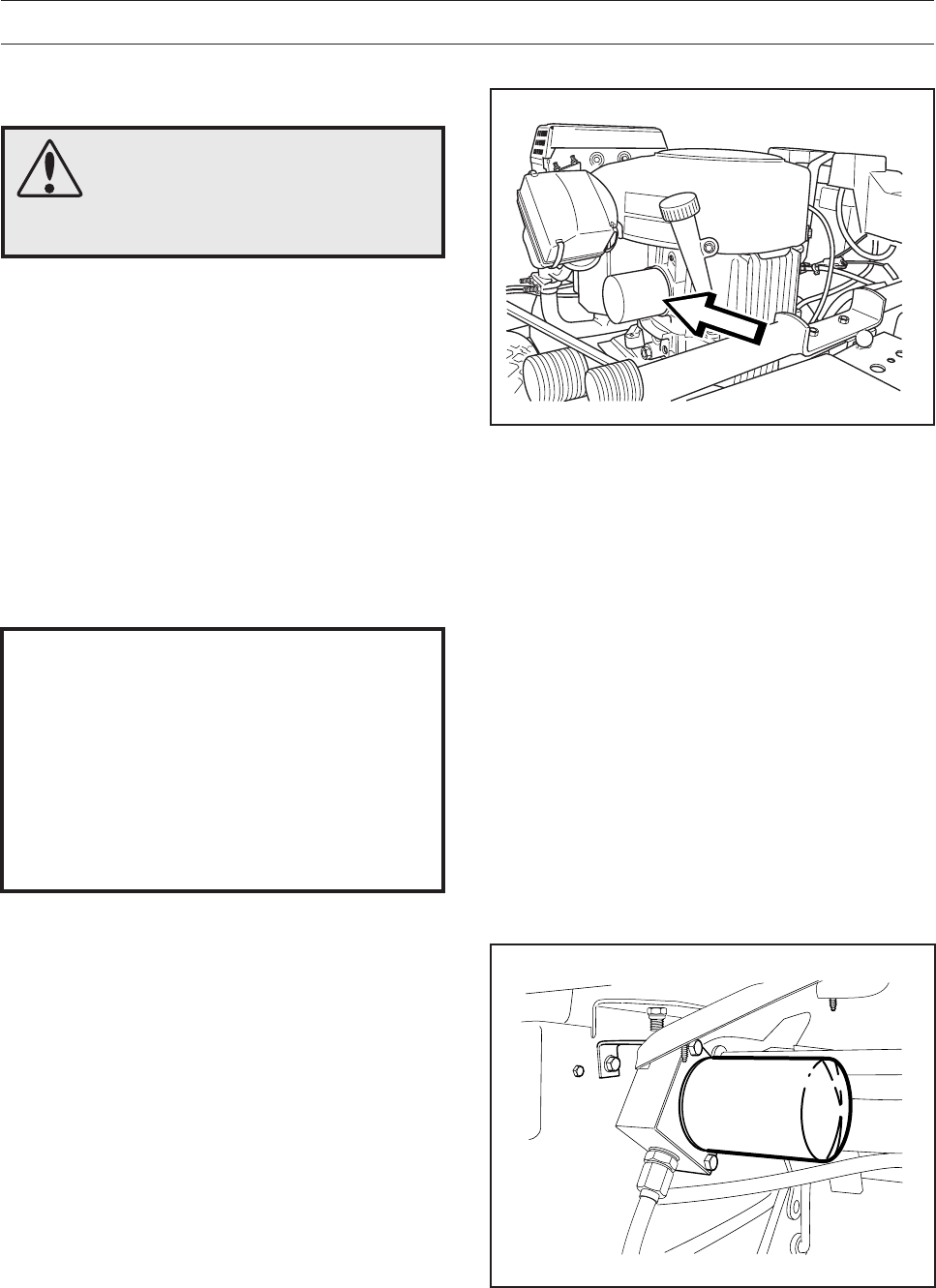
62 – English
LUBRICATION
14. Hydraulic Fluid Filter, Replacing
Pro 18, Pro 18 AWD
1. Remove the oil filter. If necessary, use a filter
remover.
2. Wipe new, clean engine oil onto the seal for the
new filter.
3. Fit the filter by hand so it just touches + 3/4 turn.
4. Remove the transmission cover and fill the
transmission’s oil tank, about 0.3 l oil.
See ”11-12. Transmission Oil Level”. Be
observant when running the engine as described
below and fill so that the tank is not emptied.
5. Run the engine warm, manipulate the servo
steering, and then check that there are no leaks
around the oil filter seal.
6. Check the oil level in the transmission, top up if
necessary. The oil filter holds 0.3 litres of oil.
7. Replace the transmission cover.
1. Open the engine cover.
2. Remove the oil filter. If necessary, use a filter
remover.
3. Wipe new, clean engine oil onto the seal for the
new filter.
4. Fit the filter by hand with + 3/4 turn.
5. Run the engine warm, then check that there are
no leaks around the oil filter seal.
6. Check the oil level in the engine, top up if
necessary. The oil filter holds 0.2 litres of oil.
13. Oil Filter, Change
WARNING!
Engine oil can be very hot if it is
drained directly after stopping
the engine. Allow the engine to
cool somewhat first.
8009-161
IMPORTANT INFORMATION
Used engine or transmission oil is health-
impairing and must not be disposed of in
the ground or in nature.
Replaced filters must be handed in to the
workshop or other allotted place for
disposal.
Avoid skin contact; wash with soap and
water in case of spills.
8009-507
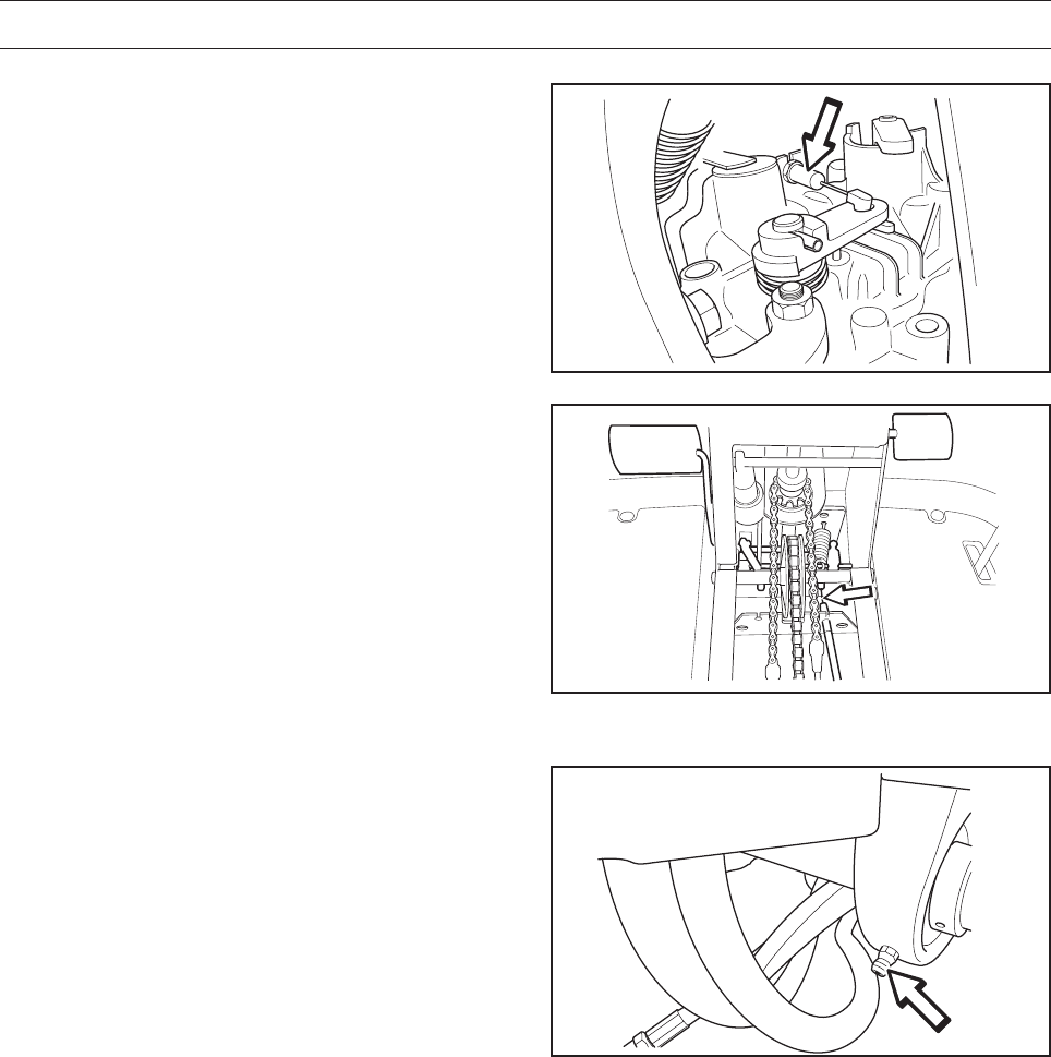
English – 63
LUBRICATION
15. Parking Brake Cable Pro 18 AWD
Remove the cover over the frame tunnel.
Lubricate both ends of the cable.
Remove the cable’s rubber casing when lubricating.
Lubricate the cable with an oilcan, press the brake
pedal a few times and lubricate again.
Replace the cover on the frame tunnel.
8009-654
8009-691
16. Right Rear Axle Bearing
Lubricate with a grease gun until grease appears
on Pro AWD.
8009-686

64 – English
TROUBLE SHOOTING GUIDE
Problem Cause
The engine will not start • No fuel in the fuel tank
• Faulty spark plugs (choke with a warm engine)
• Faulty or interchanged spark plug connections
• Dirt in the carburettor or fuel line, aged fuel
Starter does not turn the engine • Discharged battery
• Poor contact on the battery terminal cable
connectors
• Lifting lever for the cutting unit in the wrong position
• Main fuse blown. The fuse is placed in front of the
battery, under the battery cover
• Faulty ignition switch
• Hydrostat pedals not in the neutral position
• Faulty starter motor
The engine runs erratically • Faulty spark plugs
• Incorrect carburettor setting
• Clogged air filter
• Blocked fuel tank ventilation
• Incorrect ignition setting
• Dirt in the carburettor or fuel line, aged fuel
• Choking or incorrectly adjusted choke cable
The engine lacks power • Clogged air filter
• Faulty spark plugs
• Dirt in the carburettor or fuel line, aged fuel
• Incorrect carburettor setting
• Choking or incorrectly adjusted choke cable
Engine overheating • Engine overloaded
• Partial braking (forgotten parking brake?)
• Air intake or cooling fins clogged
• Damaged fan
• Too little or no oil in the engine
• Faulty pre-ignition
• Faulty spark plugs
Battery does not charge • One or more battery cells faulty
• Poor contact on the battery terminal cable
connectors
The Rider vibrates • The blades are loose
• The engine is loose
• Imbalance on one or more blades, due to damage
or inferior balancing after grinding
Uneven mowing results • Blades dull
• Cutting unit set incorrectly
• Tall or wet grass
• Grass build up under the cover
• Different air pressure in the right and left-hand tyres
• Driving speed too high
• Engine speed too low
• Drive belt slips
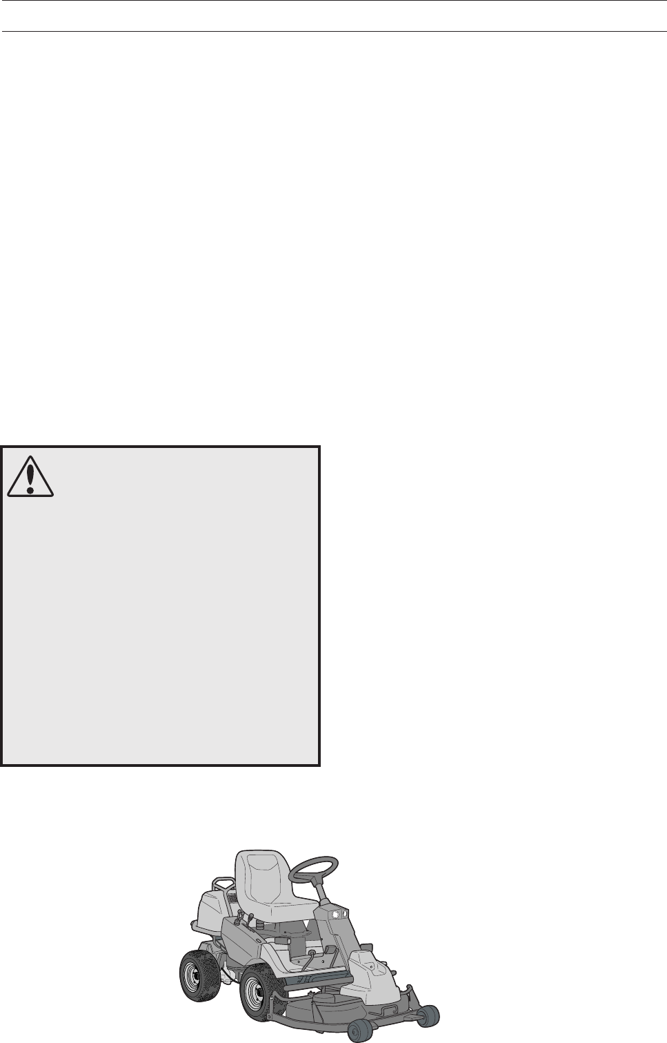
English – 65
STORAGE
To ready the Rider for storage, follow these steps:
1. Clean the Rider carefully, especially under the
cutting unit. Touch up damaged paint to prevent
rust.
2. Inspect the Rider for worn or damaged parts
and tighten any nuts or bolts that may have
become loose.
3. Change the engine oil; dispose of properly.
4. Empty the fuel tank. Start the engine and let it
run so that even the petrol in the carburettor is
emptied.
5. Remove the spark plugs and pour about a
tablespoon of engine oil into each cylinder. Turn
over the engine so that the oil is evenly
distributed and then refit the spark plugs.
6. Lubricate all grease nipples, joints, and shafts.
7. Remove the battery. Clean, charge, and store
in a cool place.
8. Store the Rider in a clean, dry place and cover
it for extra protection.
Cover
There is a cover to protect your machine during
storage or transport. Contact your dealer for a
demonstration.
Service
Low season is the most suitable time to perform a
service or overhaul of the machine in order to ensure
high functional safety during the high season.
When ordering spare parts, please specify the
Rider’s year of purchase, model, type, and serial
number.
Always use genuine Husqvarna spare parts.
An annual check-up or trimming at an authorised
service representative is a good way to ensure that
your Rider performs at its best the following season.
WARNING!
Never store an engine with fuel in
the tank indoors or in poorly
ventilated spaces where fuel
vapour can come in contact with
open flames, sparks or a pilot
light such as in a boiler, hot water
tank, clothes drier, etc.
Handle the fuel with caution. It is
very flammable and careless use
can cause serious damage to
person and property. Drain the
fuel into an approved container
outdoors and far away from open
flames.
Never use petrol for cleaning. Use
a degreasing agent and warm
water instead.
Winter Storage
At the end of the mowing season, the Rider should
be readied for storage, likewise if it will not be in
use for more than 30 days. Fuel allowed to stand
for long periods of time (30 days or more) can leave
sticky residues that can clog the carburettor and
disrupt engine function.
Fuel stabilizers are an acceptable option as regards
sticky residues during storage. If alkylate petrol is
used, stabilisers are unnecessary because this fuel
is stable. However, you should avoid switching
between standard and alkylate petrol as sensitive
rubber components can harden. Add stabiliser to
the fuel in the tank or in the storage container.
Always use the mixing ratios specified by the
manufacturer of the stabiliser. Run the engine for at
least 10 minutes after adding the stabiliser so that it
reaches the carburettor. Do not empty the fuel tank
and the carburettor if you have added stabiliser.
8009-481
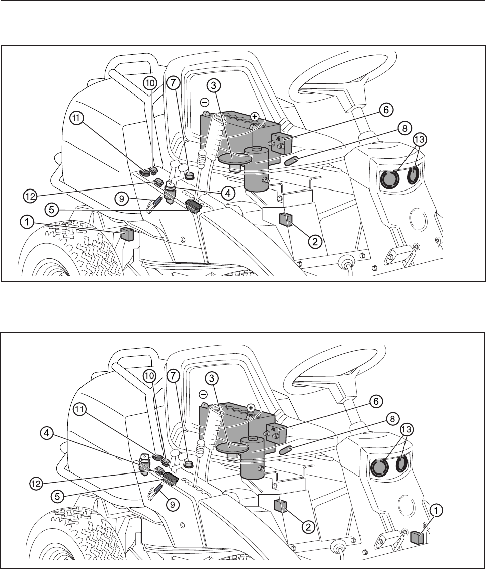
66 – English
WIRING DIAGRAM
8009-570
1. Microswitch, hydrostatic transmission
2. Microswitch, cutting unit
3. Microswitch, seat
4. Ignition key
5. Chronometer
6. Start relay
7. Engine
8. Main fuse 15 A
9. Fuse 7.5 A
10. Switch for the power outlet
11. Power outlet
12. Switch for the lights
13. Lights
Colour Abbreviations:
RD = Red
BL = Blue
VT = White
SV = Black
GL = Yellow
BR = Brown
GR = Green
Rider Pro 15 -18
Rider Pro 18 AWD
8009-678
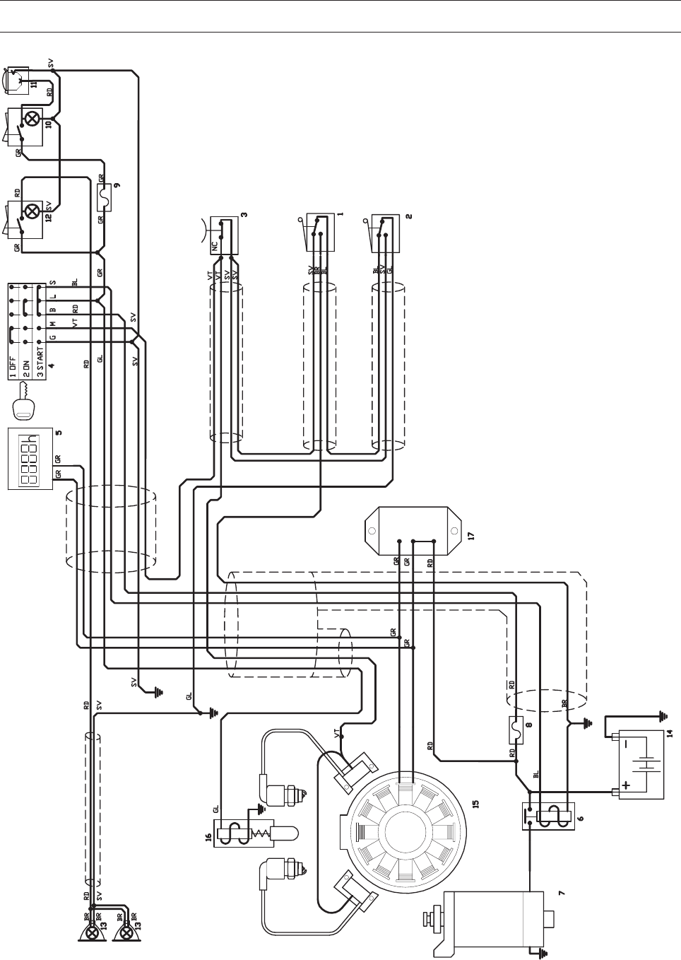
English – 67
WIRING DIAGRAM
8009-588
Rider Pro 15 -18
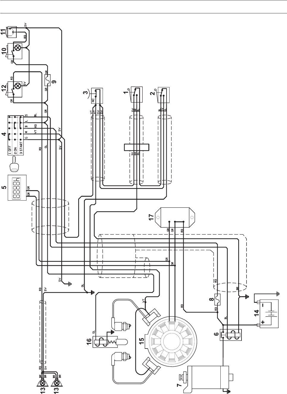
68 – English
WIRING DIAGRAM
Rider Pro 18 AWD 8009-679

English – 69
TECHNICAL DATA
Dimensions Rider Pro 15 Rider Pro 18 Rider Pro 18 AWD
Length without the cutting unit 2,030 mm / 6.65 ft 2,030 mm / 6.65 ft 2,030 mm / 6.65 ft
Width without the cutting unit 900 mm / 2.95 ft 900 mm / 2.95 ft 900 mm / 2.95 ft
Height 1,130 mm / 3.70 ft 1,130 mm / 3.70 ft 1,130 mm / 3.70 ft
Service weight without
the cutting unit 245 kg / 540 lb 261 kg / 576 lb 284 kg / 626 lb
Distance between axles 873 mm / 2.86 ft 873 mm / 2.86 ft 873 mm / 2.86 ft
Tyre dimensions 165 / 60-8 165 / 60-8 165 / 60-8
Air pressure rear - front 60 kPa (0.6 kp/cm2) 60 kPa (0.6 kp/cm2) 60 kPa (0.6 kp/cm2)
Max. permitted slope 15° 15° 15°
Engine
Manufacturer Kawasaki Kawasaki Kawasaki
Model FH430V-BS50 FH531V-DS50 FH531V-DS50
Power 11 kW/15 hp 13.2 kW/18 hp 13.2 kW/18 hp
Displacement 431 cm3 / 26.3 cu.in. 494 cm3 / 30.1 cu.in. 494 cm3 / 30.1 cu.in.
Fuel at least 87 octane unleaded at least 87 octane unleaded at least 87 octane unleaded
(Max. methanol 5 %, max (Max. methanol 5 %, max (Max. methanol 5 %, max
ethanol 10 %, max MTBE 15 %) ethanol 10 %, max MTBE 15 %) ethanol 10 %, max MTBE 15 %)
Tank volume 14 litres 14 litres 14 litres
Oil SAE 30, SAE 10W/30, SAE 30, SAE 10W/30, SAE 30, SAE 10W/30,
SAE 10W/40 class SF - SJ SAE 10W/40 class SF - SJ SAE 10W/40 class SF - SJ
Oil volume 1.5 litres/1.6 US qt 1.5 litres/1.6 US qt 1.5 litres/1.6 US qt
Oil volume including filter 1.7 litres/1.8 US qt 1.7 litres/1.8 US qt 1.7 litres/1.8 US qt
Starting Electric start Electric start Electric start
Noise emissions and mowing width
Combi 94
Measured sound power 99 dB(A) 99 dB(A) 99 dB(A)
Guaranteed noise level 99 dB(A) 99 dB(A) 99 dB(A)
Cutting width 940 mm 940 mm 940 mm
Noise emissions and mowing width
Combi 103
Measured sound power 100 dB(A) 100 dB(A) 100 dB(A)
Guaranteed noise level 100 dB(A) 100 dB(A) 100 dB(A)
Cutting width 1,030 mm 1,030 mm 1,030 mm
Noise emissions and mowing width
Combi 112
Measured sound power 99 dB(A) 99 dB(A) 99 dB(A)
Guaranteed noise level 100 dB(A) 100 dB(A) 100 dB(A)
Cutting width 1,120 mm 1,120 mm 1,120 mm
Electrical system
Type 12 V, negative grounded 12 V, negative grounded 12 V, negative grounded
Battery 12 V, 24 Ah 12 V, 24 Ah 12 V, 24 Ah
Main fuse Flat pin, 15 A Flat pin, 15 A Flat pin, 15 A
Power outlet fuse Flat pin, 7.5 A Flat pin, 7.5 A Flat pin, 7.5 A
Spark plug Champion RCJ8Y Champion RCJ8Y Champion RCJ8Y
Electrode gap 0.75 mm/0.030" 0.75 mm/0.030" 0.75 mm/0.030"
Bulbs, halogen 12V, 20W., 44860 WFL 38° 12V, 20W., 44860 WFL 38° 12V, 20W., 44860 WFL 38°
Transmission
Manufacturer Tuff Torq K 62F Tuff Torq K 66M Front Kanzaki VFMU KTM 10
Rear Kanzaki RMU KTM10
Hydraulic pump - Tuff Torq K 66M Kanzaki KPL 10 ARH
Oil SAE 10W/30, class SF-CC SAE 10W/30, class SF-CC SAE 10W/40, class SF-CC
Cutting Unit
Number of cutting heights 7 positions 7 positions 7 positions

70 – English
TECHNICAL DATA
In order to introduce improvements the specification and design are subject to alteration without prior
notice.
Note that no legal demands whatsoever can be made with the support of the information in this
operator’s manual.
Only use original spare parts with repairs. The use of other parts invalidates the warranty.
Cutting unit Combi 94 Combi 103 Combi 112
Mowing width 940 mm / 3.08 ft 1,030 mm / 3.38 ft 1,120 mm / 3.67 ft
Cutting heights 30 - 90 mm / 1 3/16"–3 1/2" 40 - 80 mm / 0.13–0.26 ft 40 - 100 mm / 1 9/16"–3 7/8"
Cutting height setting 40 mm / 1 9/16" 35 mm / 0.11 ft 35 mm / 0.11 ft
Blade diameter 360 mm / 14" 390 mm / 1.28 ft 420 mm / 1.37 ft
Weight 52 kg / 115 lb 46 kg / 101 lb 52 kg / 115 lb
incl. nose link 2 kg / 4.41 lb
When this product is spent and is no longer used it should be returned to the
dealer or other authority for recycling.

English – 71
EU Declaration of Conformity (Only applies to Europe)
Husqvarna AB, SE-561 82 Huskvarna, Sweden, tel: +46-36-146500, declares under sole responsibility that Rider
Husqvarna Rider Pro 15, Pro 18 and Pro 18 AWD dating from 2005 serial numbers and onwards (the year is clearly
stated on the rating plate, followed by the serial number), complies with the requirements of the COUNCIL’S DIRECTIVE:
- of June 22, 1998 ”relating to machinery” 98/37/EC, annex IIA.
- of May 3, 1989 ”relating to electromagnetic compatibility” 89/336/EEC, and applicable supplements.
- of May 8, 2000 ”relating to the emission of noise to surroundings” 2000/14/EC.
Information regarding noise emissions and the mowing width, see the Technical Data.
The following harmonised standards have been applied: EN292-2, EN836.
Registered body 0404, SMP Svensk Maskinprovning AB, Fyristorgsgatan 3, SE-754 50 Uppsala, Sweden has
issued the report with number:
Pro 15: 01/901/005, 01/901/006 and 01/901/033
Pro 18: 01/901/023, 01/901/024 and 01/901/034
Pro 18 AWD: 01/901/035, 01/901/036 and 01/901/037
regarding the assessment of conformity according to annex VI to the COUNCIL’S DIRECTIVE of May 8, 2000
”relating to the emission of noise to surroundings” 2000/14/EC.
Huskvarna January 3, 2005
Roger Andersson, Development Manager/Garden Products
EU DECLARATION OF CONFORMITY

72 – English
SERVICE JOURNAL
Delivery Service
1. Fill the battery with battery acid and charge for four hours.
2. Fit the steering wheel, seat and, where applicable, other components.
3. Attach the cutting unit.
4. Adjust the cutting unit:
Adjust the lifting springs (the ”weight” of the cutting unit should be
12-15 kg, if a brush is to be used, set to maximum spring power).
Adjust the cutting unit so that its rear edge is about 2-4 mm
higher than its front edge.
Adjust the cutting unit’s cutting height setting so that the cutting
height limit is 5 mm above the unit frame at the lowest cutting
height.
5. Check that the right amount of oil is in the engine and transmission.
6. Check and adjust the air pressure in the tyres (60 kPa, 0.6 bar).
7. Connect the battery.
8. Fill the fuel tank and start the engine.
9. Check that the machine does not move in neutral.
10. Check:
Driving forwards.
Reversing.
Engaging the blades.
Safety switch in the seat.
Safety switch for the lifting lever.
The safety switch for the hydrostat pedals.
11. Check the engine speed: 2,900 ±75 rpm.
12. Bleed the hydraulic system, top up with oil if necessary.
13. Check the mounting bolts on the muffler.
14. Inform the customer about:
The need and benefit of following the service schedule.
The need and advantages of leaving the machine for service
every 300 hours.
The effects of service and maintaining a service journal on the
machine’s resale value.
Application areas for BioClip.
15. Fill in the sales certificate, etc.
Delivery service has been carried
out.
No remaining notes.
Certified:
After the First 8 Hours
1. Change engine oil.
Action
Date, mileage reading, stamp,
signature

English – 73
SERVICE JOURNAL
25-Hour Service
1. Clean the air filter’s pre-cleaner (foam plastic filter).
(Shorter intervals for dusty operating conditions.)
2. Clean the engine’s cooling air intake and the transmission’s air
intake.
3. Clean the fuel pump’s air filter.
(in dusty operating conditions).
4. Check the mounting bolts on the muffler.
Action Date, mileage reading, stamp,
signature

74 – English
SERVICE JOURNAL
50-Hour Service
1. Clean/Replace the air filter’s pre-cleaner (foam plastic filter).
(Shorter intervals for dusty operating conditions.)
2. Clean the engine’s cooling air intake and the transmission’s air
intake.
3. Clean the air cleaner’s paper filter.
4. Clean the fuel pump’s air filter.
5. Check the mounting bolts on the muffler.
6. Check/Adjust the cutting height.
7. Check/Adjust the parking brake.
8. Inspect the flame proofing/spark arrestor (extra equipment).
First after 50 hours
Change the oil in the hydraulics and drive system on AWD.
Action Date, mileage reading, stamp,
signature

English – 75
SERVICE JOURNAL
100/200-Hour Service
1. Change engine oil. Replace the oil filter every 200 hours.
2. Clean/Replace the air filter’s pre-cleaner (foam plastic filter).
3. Clean the air cleaner’s paper filter. Replace every 200 hours.
(Shorter intervals for dusty operating conditions.)
4. Clean the engine’s cooling air intake and the transmission’s air
intake.
5. Clean the cooling fins on the engine and transmissions.
6. Check the mounting bolts on the muffler.
7. Check/Adjust the cutting height.
8. Check/Adjust the parking brake.
9. Inspect the flame proofing/spark arrestor (extra equipment).
10. Clean/Replace the spark plugs.
11. Change the inline fuel filter.
12. Replace the hydraulic oil filter every 200 hours on Pro 18 and AWD.
13. Clean the fuel pump’s air filter.
14. Clean the pulse air filter.
15. Check nuts and screws for tightness.
16. Replace the suction filter in the hydraulic tank every 200 hours on
AWD.
17. Check whether the oil in the gearbox and hydraulic system needs
changing (every 200/500 hours). On Pro 18 also filter replacement.
Action Date, mileage reading, stamp,
signature

76 – English
SERVICE JOURNAL
Action Date, mileage reading, stamp,
signature
300-Hour Service
1. Inspect the machine. Additional work?
2. Change engine oil. Replace the oil filter every 200 hours.
3. Replace the air filter (foam plastic filter).
4. Replace the air filter (paper filter).
5. Clean the engine’s cooling air intake and the transmission’s air
intake.
6. Clean the cooling fins on the engine and transmissions.
7. Check the mounting bolts on the muffler.
8. Check/Adjust the cutting height.
9. Check/Adjust the parking brake.
10. Inspect the flame proofing/spark arrestor (extra equipment).
11. Clean/Replace the spark plugs.
12. Change the inline fuel filter.
13. Replace the hydraulic oil filter (every 200 hours) on Pro 18 and
AWD.
14. Clean the fuel pump’s air filter.
15. Clean the pulse air filter.
16. Check the play in the engine valves.
17. Check nuts and screws for tightness.
18. Replace the suction filter in the hydraulic tank every 200 hours on
AWD.
19. Check whether the oil in the gearbox and hydraulic system needs
changing (every 200/500 hours). On Pro 18 also filter replacement.

English – 77
Action
At Least Once Each Season
1. Change the engine oil (100 hours).
2. Clean/Replace the air filter’s pre-cleaner (foam plastic filter)
(25 hours). (Shorter intervals for dusty operating conditions.)
3. Clean/Replace the air filter’s paper filter (100 hours).
(Shorter intervals for dusty operating conditions.)
4. Clean the fuel pump’s air filter (50 hours).
5. Check the mounting bolts on the muffler.
6. Adjust the cutting height (50 hours).
7. Adjust the parking brake (50 hours).
8. Inspect the flame proofing/spark arrestor, extra equipment
(50 hours).
9. Replace the engine oil filter (200 hours).
10. Clean/Replace the spark plugs (100 hours).
11. Change the inline fuel filter (100 hours).
12. Clean/Replace the pulse air filter (100 hours).
13. Clean the cooling fins (100 hours) on the engine and
transmissions.
(Shorter intervals for dusty operating conditions.)
14. Check the play in the engine valves (300 hours).
15. Replace the hydraulic oil filter (every 200 hours) on Pro 18 and
AWD.
16. Replace the suction filter in the hydraulic tank every 200 hours on
AWD.
17. Change the oil in the hydraulic system/gearbox (200/500 hours).
On Pro 18 also filter replacement.
18. Perform the 300-hour service at an authorised service
representative.
Date, mileage reading, stamp,
signature
SERVICE JOURNAL

78 – English
SERVICE JOURNAL
Action Date, mileage reading, stamp,
signature

English – 79
SERVICE JOURNAL
Action Date, mileage reading, stamp,
signature

80 – English
SERVICE JOURNAL
Action Date, mileage reading, stamp,
signature
´®z+RÆh¶6j¨

English – 81
´®z+RÆh¶6j¨ 2005W05
115 00 07-26
