Husqvarna LGT24K54/240470 User Manual TRACTOR Manuals And Guides 1102389L
User Manual: Husqvarna LGT24K54/240470 LGT24K54/240470 HUSQVARNA TRACTOR - Manuals and Guides View the owners manual for your HUSQVARNA TRACTOR #LGT24K54240470. Home:Lawn & Garden Parts:Husqvarna Parts:Husqvarna TRACTOR Manual
Open the PDF directly: View PDF ![]() .
.
Page Count: 112 [warning: Documents this large are best viewed by clicking the View PDF Link!]

®
O7O
Owner's Manual
Gasoline containing up to 10% ethanol (EIO) is acceptable for use in this machine.
The use of any gasoline exceeding 10% ethanol (EIO) will void the product warranty.
532 44 13-60 Rev. 1
SAFETY RULES
Safe Operation Practices for Ride=On Mowers
DANGER: THiS CUTTING MACHINE iS CAPABLE OF AMPUTATING HANDS AND FEET AND THROWING OBJECTS. FAILURE
TO OBSERVE THE FOLLOWING SAFETY INSTRUCTIONS COULD RESULT iN SERIOUS iNJURY OR DEATH.
WARNING: In order to prevent accidental
starting when setting up, transporting,
adjusting or making repairs, always
disconnect spark plug wire and place
wire where it cannot contact spark plug.
WARNING: Do not coast down a hill inneu-
tral, you may lose control of the tractor.
WARNING: Tow onlythe attachments that
are recommended by and comply with
specifications of the manufacturer of your
tractor. Use common sense when towing.
Operate only at the lowest possible speed
when on aslope. Too heavy of a load,
while on a slope, is dangerous. Tires
can lose traction with the ground and
cause you to lose control of your tractor.
WARNING
Engine exhaust, some of its constituents, and certain
vehicle components contain or emit chemicals
known to the State of California to cause cancer
and birth defects or other reproductive harm.
WARNING
Battery posts, terminals and related accessories
contain lead and lead compounds, chemicals known
to the State of California to cause cancer and birth
defects or other reproductive harm. Wash hands
after handling.
I. GENERAL OPERATION
•Read, understand, and follow all instructions on the
machine and in the manual before starting.
•Do not put hands or feet near rotating parts or under
the machine. Keep clear of the discharge opening at
all times.
•Only allow responsible adults, who are familiar with
the instructions,to operate the machine.
•Clear the area of objects such as rocks, toys, wire, etc.,
which could be picked up and thrown by the blades.
•Be sure the area is clear of bystanders before
operating. Stop machine if anyone enters the area.
•Never carry passengers.
•Do not mow in reverse unless absolutely necessary.
Always look down and behind before and while
backing.
•Never direct discharged material toward anyone. Avoid
discharging material against a wall or obstruction.
Material may ricochet back toward the operator. Stop
the blades when crossing gravel surfaces.
•Do not operate machine without the entire grass catcher,
discharge chute, or other safety devices in place and
working.
•Slow down before turning.
•Never leave a running machine unattended. Always
turn off blades, set parking brake, stop engine, and
remove keys before dismounting.
•Disengage blades when not mowing. Shut off engine
and wait for all parts to come to a complete stop before
cleaning the machine, removing the grass catcher, or
unclogging the discharge chute.
•Operate machine only in daylight or good artificial
light.
•Do not operate the machine while under the influence
of alcohol or drugs.
•Watch for traffic when operating near or crossing
roadways.
•Use extra care when loading or unloading the machine
into a trailer or truck.
•Always wear eye protection when operating
machine.
•Data indicates that operators, age 60 years and above,
are involved in a large percentage of riding mower-
related injuries. These operators should evaluate their
ability to operate the riding mower safely enough to
protect themselves and others from serious injury.
•Follow the manufacturer's recommendation for wheel
weights or counterweights.
•Keep machine free of grass , leaves or other debris
build-up which can touch hot exhaust /engine parts
and burn. Do not allow the mower deck to plow leaves
or other debris which can cause build-up to occur.
Clean any oil or fuel spillage before operating or storing
the machine. Allow machine to cool before storage.
II. SLOPE OPERATION
Slopes are a major factor related to loss of control and
tip-over accidents, which can result in severe injury or
death. Operation on all slopes requires extra caution. If
you cannot back up the slope or if you feel uneasy on it,
do not mow it.
• Mow up and down slopes, not across.
• Watch for holes, ruts, bumps, rocks, or other hidden
objects. Uneven terrain could overturn the machine.
Tall grass can hide obstacles.
• Choose a low ground speed so that you will not have
to stop or shift while on the slope.
• Do not mow on wet grass. Tires may lose traction.
Always keep the machine in gear when going down
slopes. Do not shift to neutral and coast downhill.
• Avoid starting, stopping, or turning on a slope. If the
tires lose traction, disengage the blades and proceed
slowly straight down the slope.
• Keep all movement on the slopes slow and gradual.
Do not make sudden changes in speed or direction,
which could cause the machine to roll over.
• Use extra care while operating machine with grass
catchers or other attachments; they can affect the
stability of the machine. Do no use on steep slopes.
• Do not try to stabilize the machine by putting your foot
on the ground.
• Do not mow near drop-offs, ditches, or embankments.
The machine could suddenly roll over if a wheel is over
the edge or if the edge caves in.
2
SAFETY RULES
Safe Operation Practices for Ride=On Mowers
ill. CHILDREN
Tragic accidents can occur if the operator is not alert to
the presence of children. Children are often attracted to
the machine and the mowing activity. Never assume that
children will remain where you last saw them.
•Keep children out ofthe mowing area and inthe watchful
care of a responsible adult other than the operator.
•Be alert and turn machine off if a child enters the
area.
•Before and while backing, look behind and down for
small children.
•Never carry children, even with the blades shut off. They
may fall off and be seriously injured or interfere with
safe machine operation. Children who have been given
rides in the past may suddenly appear in the mowing
area for another ride and be run over or backed over
by the machine.
•Never allow children to operate the machine.
•Use extra care when approaching blind corners, shrubs,
trees, or other objects that may block your view of a
child.
IV. TOWING
•Tow only with a machine that has a hitch designed for
towing. Do not attach towed equipment except at the
hitch point.
•Follow the manufacturer's recommendation for weight
limits for towed equipment and towing on slopes.
•Never allow children or others in or on towed
equipment.
•On slopes, the weight of the towed equipment may
cause loss of traction and loss of control.
•Travel slowly and allow extra distance to stop.
V. SERVICE
SAFE HANDLING OF GASOLINE
To avoid personal injury or property damage, use extreme
care in handling gasoline. Gasoline is extremely flammable
and the vapors are explosive.
•Extinguish all cigarettes, cigars, pipes, and other
sources of ignition.
•Use only approved gasoline container.
•Never remove gas cap or add fuel with the engine
running. Allow engine to cool before refueling.
•Never fuel the machine indoors.
•Never store the machine or fuel container where there
is an open flame, spark, or pilot light such as on a water
heater or other appliances.
•Never fill containers inside a vehicle or on a truck or
trailer bed with plastic liner. Always place containers
on the ground away from your vehicle when filling.
•Remove gas-powered equipment from the truck or
trailer and refuel it on the ground. Ifthis is not possible,
then refuel such equipment with a portable container,
rather than from a gasoline dispenser nozzle.
•Keep the nozzle in contact with the rim ofthe fuel tank or
container opening at all times until fueling is complete.
Do not use a nozzle lock-open device.
•If fuel is spilled on clothing, change clothing immedi-
ately.
•Never overfill fuel tank. Replace gas cap and tighten
securely.
GENERAL SERVICE
•Never operate machine in a closed area.
•Keep all nuts and bolts tight to be sure the equipment
is in safe working condition.
•Never tamper with safety devices. Check their proper
operation regularly.
•Keep machine free of grass, leaves, or other debris
build-up. Clean oil or fuel spillage and remove anyfuel-
soaked debris. Allow machine to cool before storing.
•If you strike a foreign object, stop and inspect the
machine. Repair, if necessary, before restarting.
•Never make any adjustments or repairs with the engine
running.
•Check grass catcher components and the discharge
chute frequently and replace with manufacturer's rec-
ommended parts, when necessary.
•Mower blades are sharp. Wrap the blade or wear
gloves, and use extra caution when servicing them.
•Check brake operation frequently. Adjust and service
as required.
•Maintain or replace safety and instruction labels, as
necessary.
o
o
o
o
o
o
o
o
o
o
o
Be sure the area is clear of bystanders before operat-
ing. Stop machine if anyone enters the area.
Never carry passengers.
Do not mow in reverse unless absolutely necessary.
Always look down and behind before and while back-
ing.
Never carry children, even with the blades shut off. They
may fall off and be seriously injured or interfere with
safe machine operation. Children who have been given
rides in the past may suddenly appear in the mowing
area for another ride and be run over or backed over
by the machine.
Keep children out of the mowing area and inthe watchful
care of a responsible adult other than the operator.
Be alert and turn machine off if a child enters the
area.
Before and while backing, look behind and down for
small children.
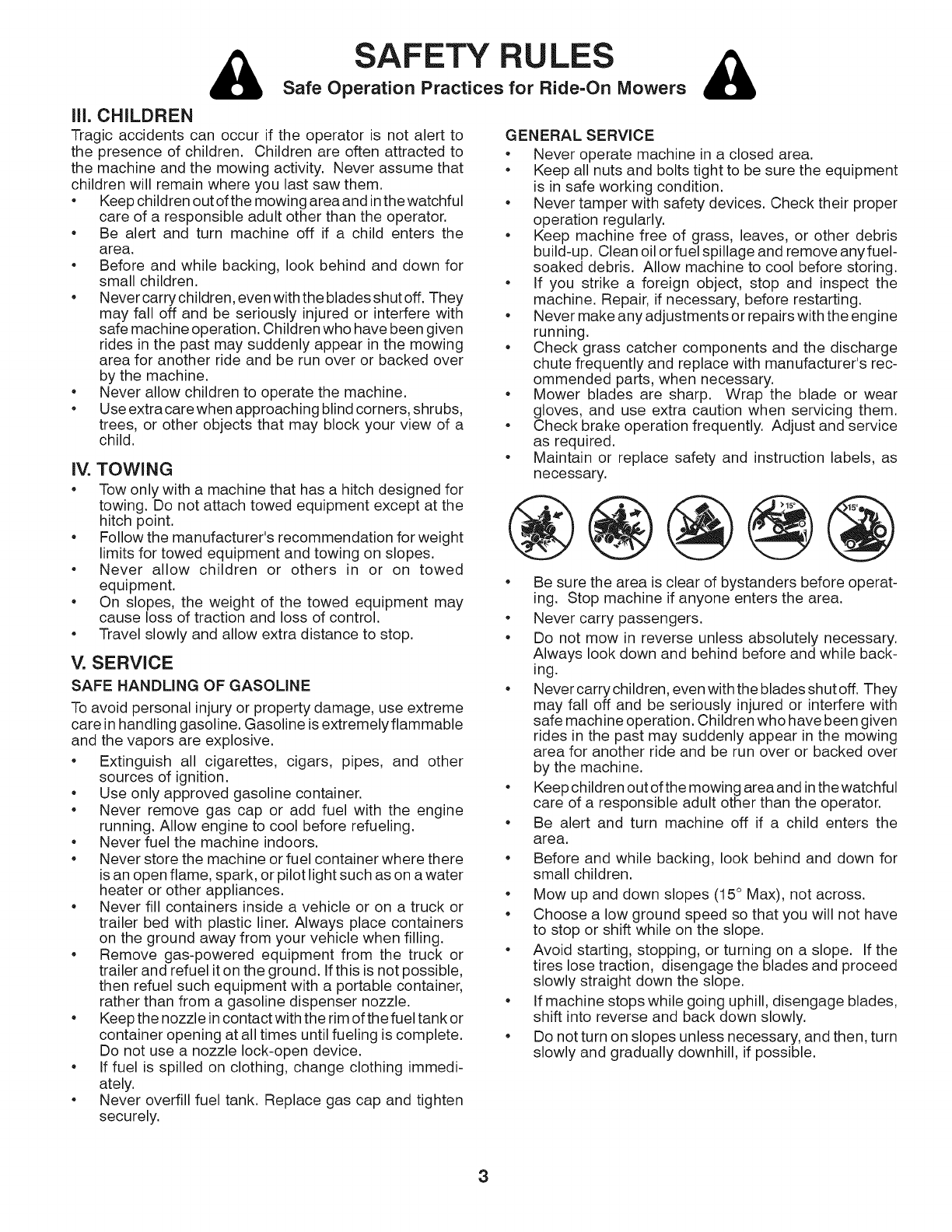
Mow up and down slopes (15° Max), not across.
Choose a low ground speed so that you will not have
to stop or shift while on the slope.
Avoid starting, stopping, or turning on a slope. If the
tires lose traction, disengage the blades and proceed
slowly straight down the slope.
If machine stops while going uphill, disengage blades,
shift into reverse and back down slowly.
Do not turn on slopes unless necessary, and then, turn
slowly and gradually downhill, if possible.
3

PRODUCT SPECiFiCATiONS
GASOLINE CAPACITY 4.0 GALLONS
AND TYPE: UNLEADED REGULAR
OIL TYPE (API: SF-SJ): SAE 30 (above 32°F)
SAE 5W-30 (below 32°F)
OIL CAPACITY: W/FILTER: 64 Oz.
W/O FILTER: 52 Oz.
SPARK PLUG: NGK BPR4ES
(Gap: .030")
GROUND SPEED (MPH): Forward: 0 - 5.2
Reverse: 0 - 2.9
CHARGING SYSTEM: 15 AMPS @ 3600 RPM
BATTERY: AMP/HR: 28
MIN. CCA: 230
CASE SIZE: U1R
BLADE BOLT TORQUE: 45-55 FT LBS.
CONGRATULATIONS on your purchase of a new tractor.
It has been designed, engineered and manufactured to give
you the best possible dependability and performance.
Should you experience any problem you cannot easily rem-
edy, please contact your nearest authorized servicecenter/
department We have competent, well-trained technicians
and the proper tools to service or repair this tractor.
Please read and retain this manual. The instructions will
enable you to assemble and maintain your tractor properly.
Always observe the "SAFETY RULES".
CUSTOMER RESPONSIBILITIES
Read and observe the safety rules.
•Follow a regular schedule in maintaining, caring for
and using your tractor.
• Follow the instructions under "Maintenance" and "Stor-
age" sections of this manual.
WARNING: This tractor is equipped with an internal com-
bustion engine and should not be used on or near any un-
improved forest-covered, brush-covered or grass-covered
land unless the engine's exhaust system is equipped with
a spark arrester meeting applicable local or state laws (if
any). If a spark arrester is used, it should be maintained
in effective working order by the operator.
In the state of California the above is required by law
(Section 4442 of the California Public Resources Code).
Other states may have similar laws. Federal laws apply
on federal lands.
A spark arrester for the muffler is available through your
nearest authorized service center/department (See REPAIR
PARTS section of this manual).
TABLE OF CONTENTS
SAFETY RULES ......................................................... 2=3
PRODUCT SPECIFICATIONS ....................................... 4
CUSTOMER RESPONSIBILITIES ................................. 4
ASSEMBLY ................................................................. 5=9
OPERATION ........................................................... 10-16
MAINTENANCE SCHEDULE ...................................... 17
MAINTENANCE ..................................................... 17=20
SERVICE AND ADJUSTMENTS ............................ 21=25
STORAGE .................................................................... 26
TROUBLESHOOTING ............................................ 27=28
REPAIR PARTS ...................................................... 29=42
REPAIR PARTS =TRANSAXLE .................................. 43
REPAIR PARTS =ENGINE ..................................... 44=48
WARRANTY ............................................................ 49=52
4
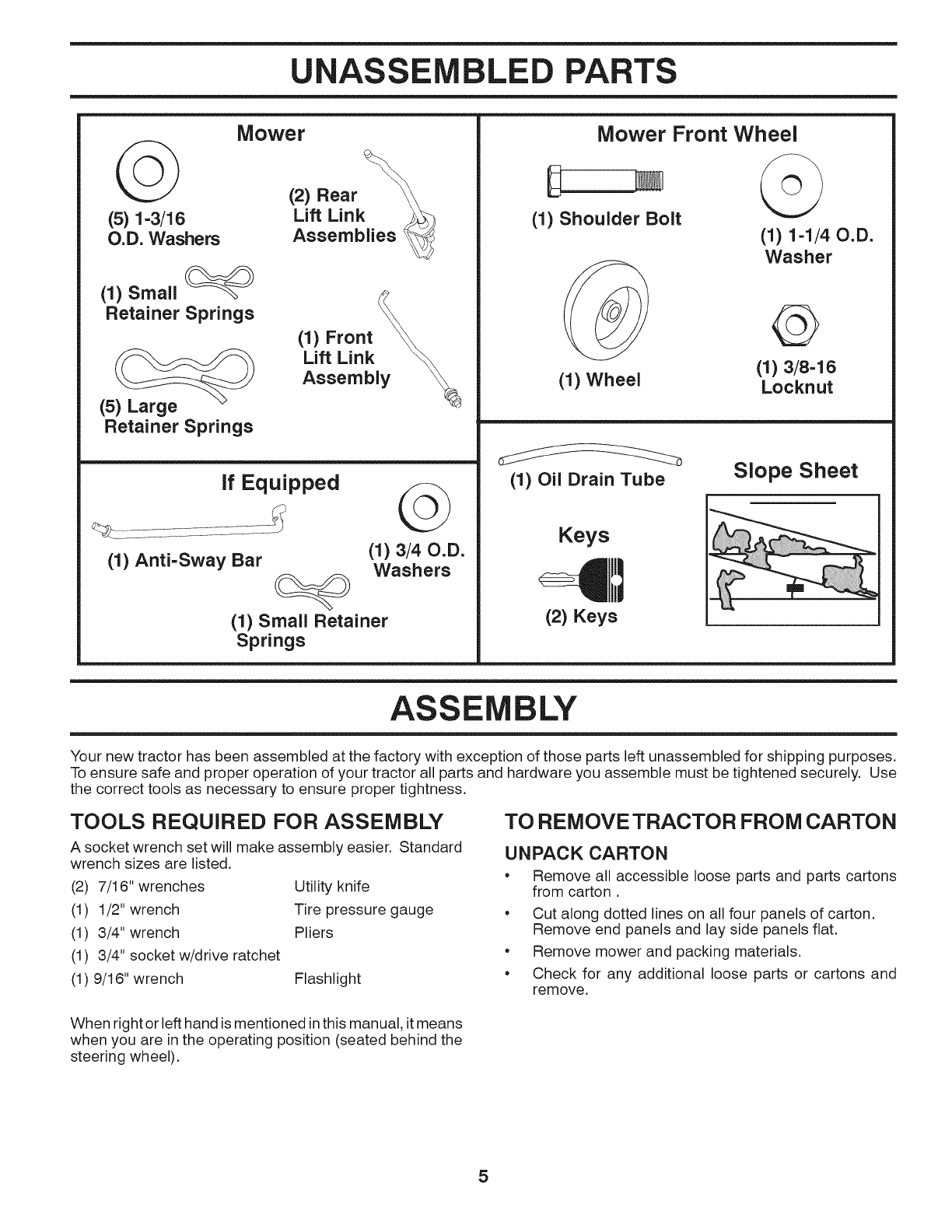
UNASSEMBLED PARTS
(5) 1-3/16
O.D. Washers
Mower
(2) Rear
Lift Link _
Assemblies
(1) Small
Retainer Springs
(5) Large
Retainer Springs
(1) Front
Lift Link
Assembly
if Equipped ©
(1) Anti-Sway Bar (1) 3/40.D.
Washers
(1) Small Retainer
Springs
Mower Front Wheel
(1) Shoulder Bolt
(1) Wheel
(i) i-i/40.D.
Washer
©
(1) 3/8-16
Locknut
(1) Oil Drain Tube Slope Sheet
Keys
(2) Keys
ASSEMBLY
Your new tractor has been assembled at the factory with exception of those parts left unassembled for shipping purposes.
To ensure safe and proper operation of your tractor all parts and hardware you assemble must be tightened securely. Use
the correct tools as necessary to ensure proper tightness.
TOOLS REQUIRED FOR ASSEMBLY
A socket wrench set will make assembly easier. Standard
wrench sizes are listed.
(2) 7/16" wrenches
(1) 1/2" wrench
(1) 3/4" wrench
(1) 3/4" socket w/drive ratchet
(1) 9/16" wrench Flashlight
Utility knife
Tire pressure gauge
Pliers
TO REMOVE TRACTOR FROM CARTON
UNPACK CARTON
• Remove all accessible loose parts and parts cartons
from carton.
• Cut along dotted lines on all four panels of carton.
Remove end panels and lay side panels flat.
• Remove mower and packing materials.
• Check for any additional loose parts or cartons and
remove.
When right or left hand is mentioned in this manual, it means
when you are in the operating position (seated behind the
steering wheel).
5
ASSEMBLY
BEFORE REMOVING TRACTOR FROM
SKiD
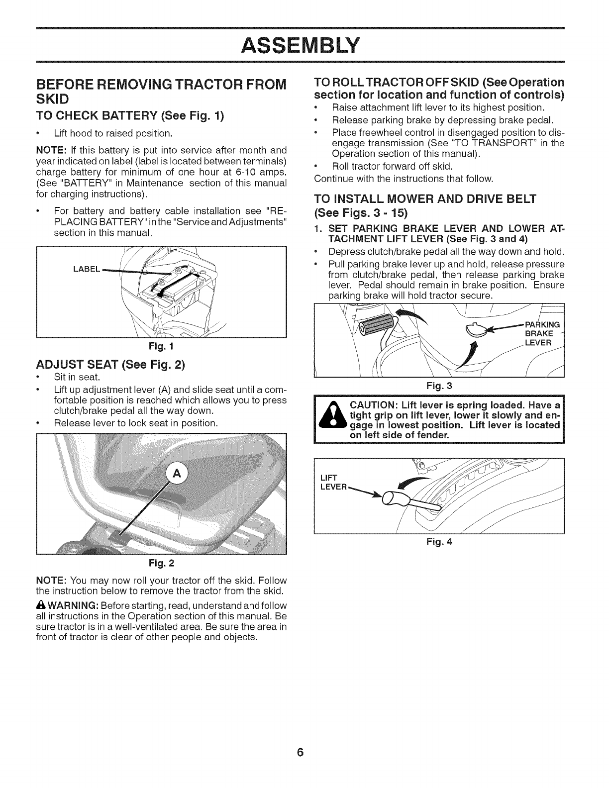
TO CHECK BATTERY (See Fig. 1)
Lift hood to raised position.
NOTE: If this battery is put into service after month and
year indicated on label (label is located between terminals)
charge battery for minimum of one hour at 6-10 amps.
(See "BATTERY" in Maintenance section of this manual
for charging instructions).
• For battery and battery cable installation see "RE-
PLACING BATTERY"in the "Service and Adjustments"
section in this manual.
Fig. 1
ADJUST SEAT (See Fig. 2)
• Sit in seat.
• Lift up adjustment lever (A) and slide seat until a com-
fortable position is reached which allows you to press
clutch/brake pedal all the way down.
• Release lever to lock seat in position.
TO ROLLTRACTOR OFF SKID (See Operation
section for location and function of controls)
• Raise attachment lift lever to its highest position.
• Release parking brake by depressing brake pedal.
• Place freewheel control in disengaged position to dis-
engage transmission (See "TO TRANSPORT" in the
Operation section of this manual).
• Roll tractor forward off skid.
Continue with the instructions that follow.
TO INSTALL MOWER AND DRIVE BELT
(See Figs. 3 - 15)
1. SET PARKING BRAKE LEVER AND LOWER AT=
TACHMENT LIFT LEVER (See Fig. 3 and 4)
• Depress clutch/brake pedal all the way down and hold.
• Pull parking brake lever up and hold, release pressure
from clutch/brake pedal, then release parking brake
lever. Pedal should remain in brake position. Ensure
parking brake will hold tractor secure.
\/
Fig. 3
CAUTION: Lift lever is spring loaded. Have a
tight grip on lift lever, lower it slowly and en=
gage in lowest position. Lift lever is located
on left side of fender.
LIFT
Fig. 2
NOTE: You may now roll your tractor off the skid. Follow
the instruction below to remove the tractor from the skid.
_k WARNING: Before starting, read, understand and follow
all instructions in the Operation section of this manual. Be
sure tractor is in a well-ventilated area. Be sure the area in
front of tractor is clear of other people and objects.
Fig. 4
6
ASSEMBLY
=
=
e
4=
e
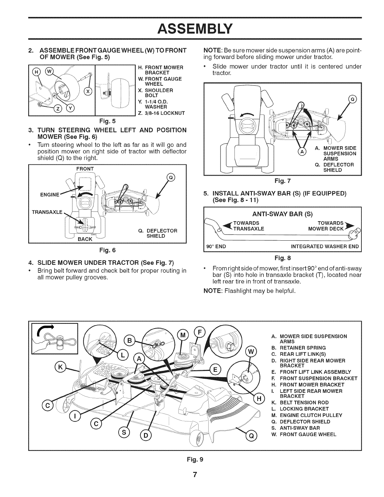
ASSEMBLE FRONT GAUGE WHEEL (W) TO FRONT
OF MOWER (See Fig. 5)
H, FRONT MOWER
BRACKET
W, FRONT GAUGE
WHEEL
X, SHOULDER
BOLT
Y. 1-1/40.D.
WASHER
Z. 3/8-18 LOCKNUT
Fig. 5
TURN STEERING WHEEL
MOWER (See Fig. 6)
LEFT AND POSITION
Turn steering wheel to the left as far as it will go and
position mower on right side of tractor with deflector
shield (Q) to the right.
FRONT
TRANSAXLE
Q. DEFLECTOR
SHIELD
Fig. 6
SLIDE MOWER UNDER TRACTOR (See Fig. 7)
Bring belt forward and check belt for proper routing in
all mower pulley grooves.
NOTE: Be sure mower side suspension arms (A) are point-
ing forward before sliding mower under tractor.
•Slide mower under tractor until it is centered under
tractor.
5=
A. MOWER SIDE
SUSPENSION
ARMS
Q. DEFLECTOR
SHIELD
Fig. 7
INSTALL ANTI-SWAY BAR (S)(IFEQUIPPED)
(See Fig.8 -1I)
ANTI-SWAY BAR (S)
_TOWARDS TOWARDS
TRANSAXLE
MOWER DECK_
90 ° END INTEGRATED WASHER END
Fig. 8
From right side of mower, first insert 90° end of anti-sway
bar (S) into hole in transaxle bracket (T), located near
left rear tire in front of transaxle.
NOTE: Flashlight may be helpful.
A. MOWER SIDE SUSPENSION
ARMS
B. RETAINER SPRING
C, REAR LIFT LINK(S)
D, RIGHT SIDE REAR MOWER
BRAC KET
E, FRONT LIFT LINK ASSEMBLY
F. FRONT SUSPENSION BRACKET
H, FRONT MOWER BRACKET
I. LEFT SIDE REAR MOWER
BRACKET
K. BELT TENSION ROD
L, LOCKING BRACKET
M, ENGINE CLUTCH PULLEY
Q. DEFLECTOR SHIELD
S. ANTI-SWAY BAR
W, FRONT GAUGE WHEEL
Fig. 9
7
ASSEMBLY
.... s_
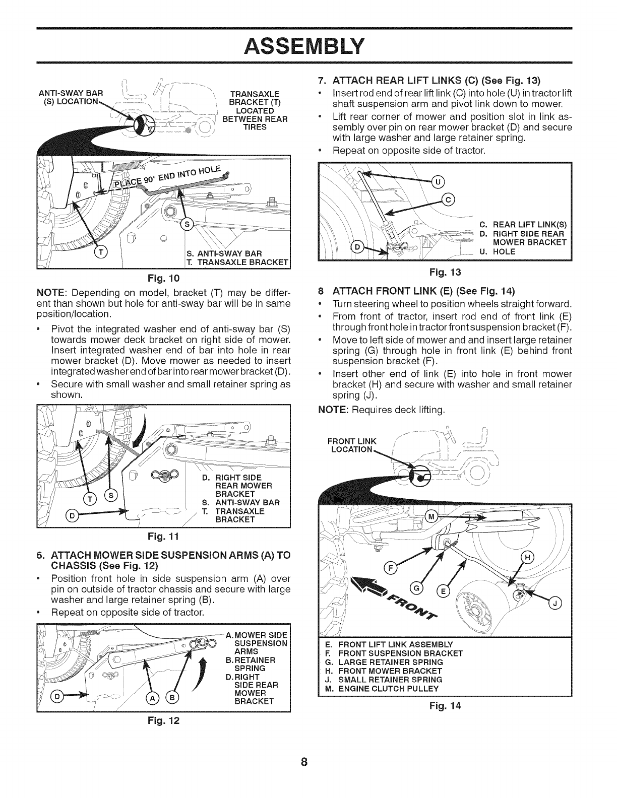
ANTI-SWAY BAR i'_,s J ........
..... TRANSAXLE
(S) BRACKET (T)
LOCATED
BETWEEN REAR
TIRES
TRANSAXLE BRACKET
Fig. 10
NOTE: Depending on model, bracket (T) may be differ-
ent than shown but hole for anti-sway bar will be in same
position/location.
• Pivot the integrated washer end of anti-sway bar (S)
towards mower deck bracket on right side of mower.
Insert integrated washer end of bar into hole in rear
mower bracket (D). Move mower as needed to insert
integrated washer end of bar into rear mower bracket (D).
• Secure with small washer and small retainer spring as
shown.
Fig. 11
6. ATTACH MOWER SIDE SUSPENSION ARMS (A) TO
CHASSIS (See Fig. 12)
Position front hole in side suspension arm (A) over
pin on outside of tractor chassis and secure with large
washer and large retainer spring (B).
• Repeat on opposite side of tractor.
Fig. 12
SUSPENSION
ARMS
B. RETAINER
SPRING
D. RIGHT
SIDE REAR
MOWER
BRACKET
7. ATTACH REAR LiFT LINKS (C) (See Fig. 13)
• Insert rod end of rear lift link (C) into hole (U) in tractor lift
shaft suspension arm and pivot link down to mower.
• Lift rear corner of mower and position slot in link as-
sembly over pin on rear mower bracket (D) and secure
with large washer and large retainer spring.
• Repeat on opposite side of tractor.
I_ C. REAR LIFT LINK(S)
",,'i', ',,t_n"L _ _'_/\" " _ MOWER BRACKET
I' ...... U. HOLE
Fig. 13
8 ATTACH FRONT LINK (E) (See Fig. 14)
Turn steering wheel to position wheels straightforward.
•From front of tractor, insert rod end of front link (E)
through front hole in tractor front suspension bracket (F).
Move to left side of mower and and insert large retainer
spring (G) through hole in front link (E) behind front
suspension bracket (F).
•Insert other end of link (E) into hole in front mower
bracket (H) and secure with washer and small retainer
spring (J).
NOTE: Requires deck lifting.
FRONT LINK /_........
LOCATION, /,,
E. FRONT LIFT LINK ASSEMBLY
F. FRONT SUSPENSION BRACKET
G. LARGE RETAINER SPRING
H. FRONT MOWER BRACKET
J. SMALL RETAINER SPRING
M. ENGINE CLUTCH PULLEY
Fig. 14
8
ASSEMBLY
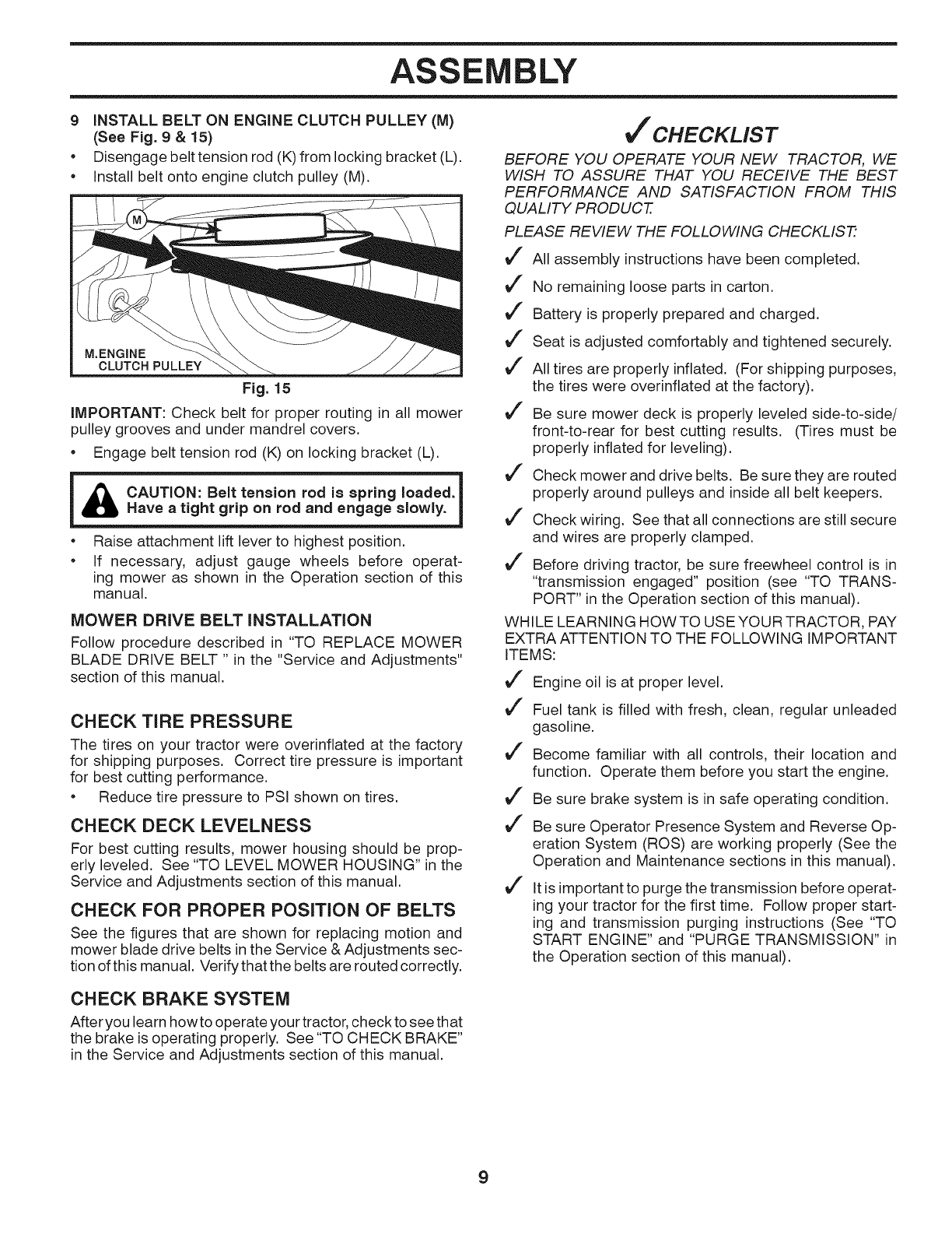
9 iNSTALL BELT ON ENGINE CLUTCH PULLEY (M)
(See Fig. 9 & 15)
• Disengage belt tension rod (K) from locking bracket (L).
• Install belt onto engine clutch pulley (M).
M.ENGINE
CLUTCH PULLEY
Fig. 15
iMPORTANT: Check belt for proper routing in all mower
pulley grooves and under mandrel covers.
•Engage belt tension rod (K) on locking bracket (L).
l& CAUTION: Belt tension rod is spring loaded.|
I
Have a tight grip on rod and engage slowly. l
•Raise attachment lift lever to highest position.
•If necessary, adjust gauge wheels before operat-
ing mower as shown in the Operation section of this
manual.
MOWER DRIVE BELT INSTALLATION
Follow procedure described in "TO REPLACE MOWER
BLADE DRIVE BELT " in the "Service and Adjustments"
section of this manual.
CHECK TiRE PRESSURE
The tires on your tractor were overinflated at the factory
for shipping purposes. Correct tire pressure is important
for best cutting performance.
•Reduce tire pressure to PSI shown on tires.
CHECK DECK LEVELNESS
For best cutting results, mower housing should be prop-
erly leveled. See "TO LEVEL MOWER HOUSING" in the
Service and Adjustments section of this manual.
CHECK FOR PROPER POSITION OF BELTS
See the figures that are shown for replacing motion and
mower blade drive belts in the Service & Adjustments sec-
tion of this manual. Verifythat the belts are routed correctly.
CHECK BRAKE SYSTEM
After you learn how to operate your tractor, check to see that
the brake is operating properly. See "TO CHECK BRAKE"
in the Service and Adjustments section of this manual.
Vf CHECKLIST
BEFORE YOU OPERATE YOUR NEW TRACTOR, WE
WtSH TO ASSURE THAT YOU RECEIVE THE BEST
PERFORMANCE AND SATISFACTION FROM THIS
QUALITY PRODUCT.
PLEASE REVIEW THE FOLLOWING CHECKLIST:
J" All assembly instructions have been completed.
J" No remaining loose parts in carton.
J" Battery is properly prepared and charged.
J" Seat is adjusted comfortably and tightened securely.
J" All tires are properly inflated. (For shipping purposes,
the tires were overinflated at the factory).
J" Be sure mower deck is properly leveled side-to-side/
front-to-rear for best cutting results. (Tires must be
properly inflated for leveling).
J" Check mower and drive belts. Be sure they are routed
properly around pulleys and inside all belt keepers.
J" Check wiring. See that all connections are still secure
and wires are properly clamped.
J" Before driving tractor, be sure freewheel control is in
"transmission engaged" position (see "TO TRANS-
PORT" in the Operation section of this manual).
WHILE LEARNING HOWTO USEYOUR TRACTOR, PAY
EXTRA ATTENTION TO THE FOLLOWING IMPORTANT
ITEMS:
J" Engine oil is at proper level.
J" Fuel tank is filled with fresh, clean, regular unleaded
gasoline.
J" Become familiar with all controls, their location and
function. Operate them before you start the engine.
J" Be sure brake system is in safe operating condition.
J" Be sure Operator Presence System and Reverse Op-
eration System (ROS) are working properly (See the
Operation and Maintenance sections in this manual).
J" It is important to purge the transmission before operat-
ing your tractor for the first time. Follow proper start-
ing and transmission purging instructions (See "TO
START ENGINE" and "PURGE TRANSMISSION" in
the Operation section of this manual).
9
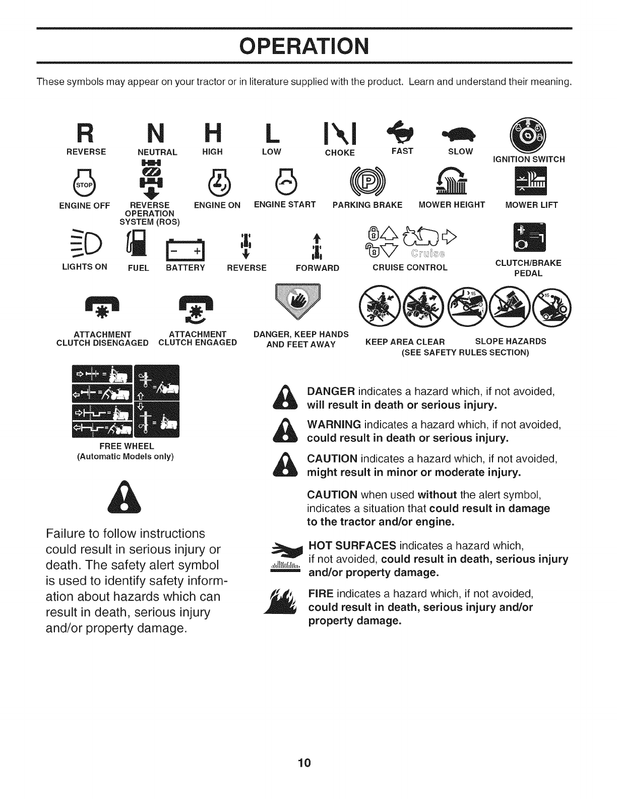
OPERATION
These symbols may appear on your tractor or in literature supplied with the product. Learn and understand their meaning.
LOW CHOKE FAST SLOWREVERSE NEUTRAL HIGH
6 O (®) -@
ENGINE OFF REVERSE ENGINE ON ENGINE START PARKING BRAKE MOWER HEIGHT
OPERATION
SYSTEM (ROS)
FUEL BATTERY
LIGHTS ON REVERSE FORWARD CRUISE CONTROL
IGNITION SWITCH
MOWER LIFT
CLUTCH/BRAKE
PEDAL
ATTACH M ENT
CLUTCH DISENGAGED ATTACHMENT
CLUTCH ENGAGED
FREE WHEEL
(Automatic Models only)
DANGER, KEEP HANDS
AND FEETAWAY KEEP AREA CLEAR SLOPE HAZARDS
(SEE SAFETY RULES SECTION)
Failure to follow instructions
could result in serious injury or
death. The safety alert symbol
is used to identify safety inform-
ation about hazards which can
result in death, serious injury
and/or property damage.
,&
,&
&
DANGER indicates a hazard which, if not avoided,
will result in death or serious injury.
WARNING indicates a hazard which, if not avoided,
could result in death or serious injury.
CAUTION indicates a hazard which, if not avoided,
might result in minor or moderate injury.
CAUTION when used without the alert symbol,
indicates a situation that could result in damage
to the tractor and/or engine.
HOT SURFACES indicates a hazard which,
if not avoided, could result in death, serious injury
and/or property damage.
FIRE indicates a hazard which, if not avoided,
could result in death, serious injury and/or
property damage.
10
OPERATION
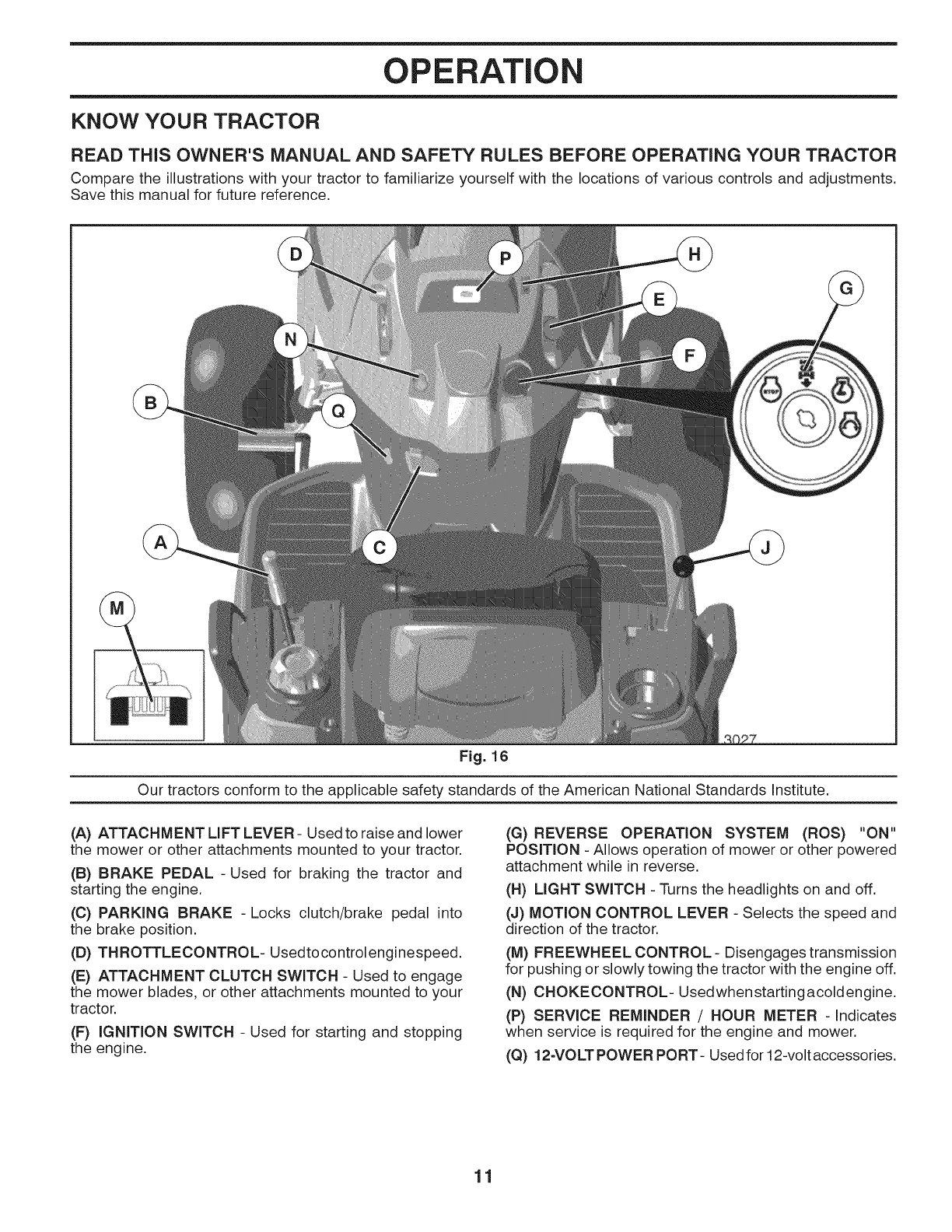
KNOW YOUR TRACTOR
READ THiS OWNER'S MANUAL AND SAFETY RULES BEFORE OPERATING YOUR TRACTOR
Compare the illustrations with your tractor to familiarize yourself with the locations of various controls and adjustments.
Save this manual for future reference.
Fig. 16
Our tractors conform to the applicable safety standards of the American National Standards Institute.
(A) ATTACHMENT LIFT LEVER - Used to raise and lower
the mower or other attachments mounted to your tractor.
(B) BRAKE PEDAL -Used for braking the tractor and
starting the engine.
(C) PARKING BRAKE -Locks clutch/brake pedal into
the brake position.
(D) THROTTLECONTROL- Usedtocontrolenginespeed.
(E) ATTACHMENT CLUTCH SWITCH - Used to engage
the mower blades, or other attachments mounted to your
tractor.
(F) IGNITION SWITCH - Used for starting and stopping
the engine.
(G) REVERSE OPERATION SYSTEM (ROS) "ON"
POSITION - Allows operation of mower or other powered
attachment while in reverse.
(H) LIGHT SWITCH - Turns the headlights on and off.
(J) MOTION CONTROL LEVER - Selects the speed and
direction of the tractor.
(M) FREEWHEEL CONTROL - Disengages transmission
for pushing or slowly towing the tractor with the engine off.
(N) CHOKECONTROL- Usedwhenstartingacoldengine.
(P) SERVICE REMINDER /HOUR METER -Indicates
when service is required for the engine and mower.
(Q) 12-VOLT POWER PORT- Used for 12-volt accessories.
11
OPERATION
The operation of any tractor can result in foreign objects thrown into the eyes, which can
result in severe eye damage. Always wear safety glasses or eye shields while operating
your tractor or performing any adjustments or repairs. We recommend standard safety
glasses or a wide vision safety mask worn over spectacles.
HOW TO USE YOUR TRACTOR
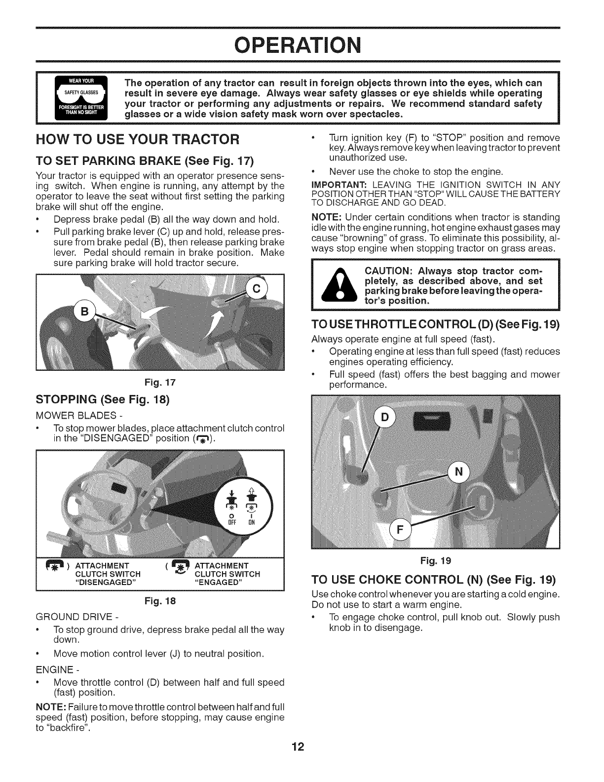
TO SET PARKING BRAKE (See Fig. 17)
Your tractor is equipped with an operator presence sens-
ing switch. When engine is running, any attempt by the
operator to leave the seat without first setting the parking
brake will shut off the engine.
• Depress brake pedal (B) all the way down and hold.
• Pull parking brake lever (C) up and hold, release pres-
sure from brake pedal (B), then release parking brake
lever. Pedal should remain in brake position. Make
sure parking brake will hold tractor secure.
• Turn ignition key (F) to "STOP" position and remove
key. Always remove key when leaving tractor to prevent
unauthorized use.
•Never use the choke to stop the engine.
IMPORTANT: LEAVING THE IGNITION SWITCH IN ANY
POSITION OTHER THAN "STOP" WILL CAUSE THE BATTERY
TO DISCHARGE AND GO DEAD.
NOTE: Under certain conditions when tractor is standing
idle with the engine running, hot engine exhaust gases may
cause "browning" of grass. To eliminate this possibility, al-
ways stop engine when stopping tractor on grass areas.
ACAUTION: Always stop tractor corn=
pletely, as described above, and set
parking brake before leaving the opera=
tot's position.
Fig. 17
STOPPING (See Fig. 18)
MOWER BLADES -
• To stop mower blades, place attachment clutch control
in the "DISENGAGED" position (t_).
TO USE TH ROTTLE CONTROL (D) (See Fig. 19)
Always operate engine at full speed (fast).
• Operating engine at less than full speed (fast) reduces
engines operating efficiency.
• Full speed (fast) offers the best bagging and mower
performance.
|
_) ATTACHMENT
CLUTCH SWITCH
"DISENGAGED"
( _ ATTACHMENT
CLUTCH SWITCH
"ENGAGED"
Fig. 18
GROUND DRIVE -
• To stop ground drive, depress brake pedal all the way
down.
• Move motion control lever (J) to neutral position.
ENGINE -
• Move throttle control (D) between half and full speed
(fast) position.
NOTE: Failure to move throttle control between half and full
speed (fast) position, before stopping, may cause engine
to "backfire".
Fig. 19
TO USE CHOKE CONTROL (N) (See Fig. 19)
Use choke control whenever you are starting a cold engine.
Do not use to start a warm engine.
• To engage choke control, pull knob out. Slowly push
knob in to disengage.
12
OPERATION
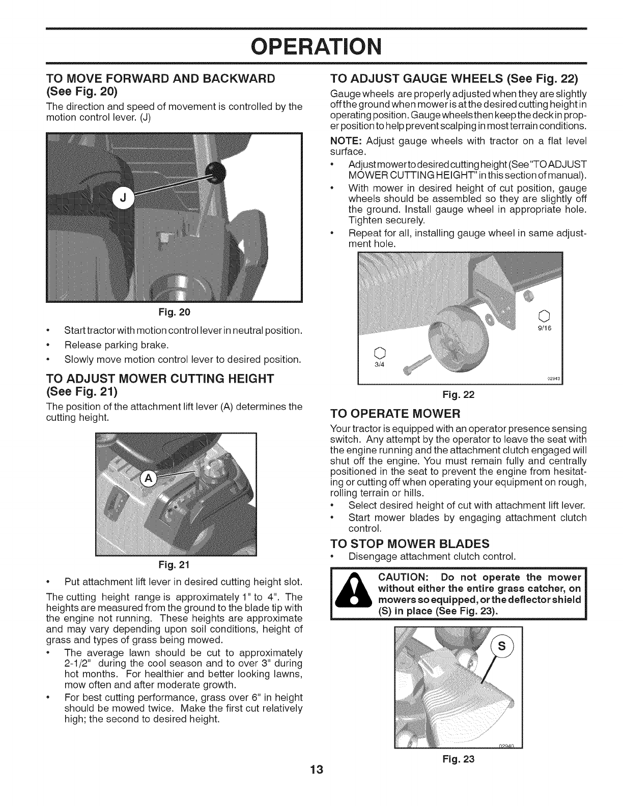
TO MOVE FORWARD AND BACKWARD
(See Fig. 20)
The direction and speed of movement is controlled by the
motion control lever. (J)
TO ADJUST GAUGE WHEELS (See Fig. 22)
Gauge wheels are properly adjusted when they are slightly
off the ground when mower is at the desired cutting height in
operating position. Gauge wheels then keep the deck inprop-
er position to help prevent scalping in most terrain conditions.
NOTE: Adjust gauge wheels with tractor on a flat level
surface.
• Adjust mower to desired cutting height (See"TOADJUST
MOWER CUTTING HEIGHT" inthis section of manual).
• With mower in desired height of cut position, gauge
wheels should be assembled so they are slightly off
the ground. Install gauge wheel in appropriate hole.
Tighten securely.
• Repeat for all, installing gauge wheel in same adjust-
ment hole.
Fig. 20
• Start tractor with motion control lever in neutral position.
• Release parking brake.
• Slowly move motion control lever to desired position.
TO ADJUST MOWER CUTTING HEIGHT
(See Fig. 21)
The position of the attachment lift lever (A) determines the
cutting height.
Fig. 21
• Put attachment lift lever in desired cutting height slot.
The cutting height range is approximately 1" to 4". The
heights are measured from the ground to the blade tip with
the engine not running. These heights are approximate
and may vary depending upon soil conditions, height of
grass and types of grass being mowed.
• The average lawn should be cut to approximately
2-1/2" during the cool season and to over 3" during
hot months. For healthier and better looking lawns,
mow often and after moderate growth.
• For best cutting performance, grass over 6" in height
should be mowed twice. Make the first cut relatively
high; the second to desired height.
©
3/4
Fig. 22
TO OPERATE MOWER
Your tractor is equipped with an operator presence sensing
switch. Any attempt by the operator to leave the seat with
the engine running and the attachment clutch engaged will
shut off the engine. You must remain fully and centrally
positioned in the seat to prevent the engine from hesitat-
ing or cutting off when operating your equipment on rough,
rolling terrain or hills.
• Select desired height of cut with attachment lift lever.
• Start mower blades by engaging attachment clutch
control.
TO STOP MOWER BLADES
• Disengage attachment clutch control.
_CAUTION: Do not operate the mower
without either the entire grass catcher, on
mowers so equipped, or the deflector shield
(S) in place (See Fig. 23).
Fig. 23
13
OPERATION
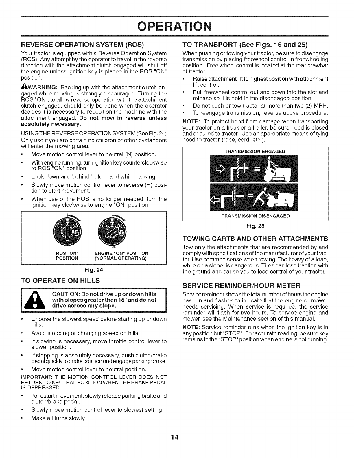
REVERSE OPERATION SYSTEM (ROS)
Your tractor is equipped with a Reverse Operation System
(ROS). Any attempt by the operator to travel in the reverse
direction with the attachment clutch engaged will shut off
the engine unless ignition key is placed in the ROS "ON"
position.
_I_WARNING: Backing up with the attachment clutch en-
gaged while mowing is strongly discouraged. Turning the
ROS "ON", to allow reverse operation with the attachment
clutch engaged, should only be done when the operator
decides it is necessary to reposition the machine with the
attachment engaged. Do not mow in reverse unless
absolutely necessary.
USINGTHE REVERSE OPERATION SYSTEM (See Fig. 24)
Only use if you are certain no children or other bystanders
will enter the mowing area.
•Move motion control lever to neutral (N) position.
•With engine running, turn ignition key counterclockwise
to ROS "ON" position.
•Look down and behind before and while backing.
•Slowly move motion control lever to reverse (R) posi-
tion to start movement.
•When use of the ROS is no longer needed, turn the
ignition key clockwise to engine "ON" position.
ROS "ON"
POSITION
ENGINE "ON" POSITION
(NORMAL OPERATING)
Fig. 24
TO OPERATE ON HILLS
CAUTION: Do not drive up or down hills
with slopes greater than 15° and do not
drive across any slope.
•Choose the slowest speed before starting up or down
hills.
•Avoid stopping or changing speed on hills.
•If slowing is necessary, move throttle control lever to
slower position.
•If stopping is absolutely necessary, push clutch/brake
pedal quicklyto brake position and engage parking brake.
•Move motion control lever to neutral position.
iMPORTANT: THE MOTION CONTROL LEVER DOES NOT
RETURN TO NEUTRALPOSITIONWHEN THE BRAKE PEDAL
IS DEPRESSED.
•To restart movement, slowly release parking brake and
clutch/brake pedal.
•Slowly move motion control lever to slowest setting.
•Make all turns slowly.
TO TRANSPORT (See Figs. 16 and 25)
When pushing or towing your tractor, be sure to disengage
transmission by placing freewheel control in freewheeling
position. Free wheel control is located at the rear drawbar
of tractor.
•Raise attachment lift to highest position with attachment
lift control.
•Pull freewheel control out and down into the slot and
release so it is held in the disengaged position.
•Do not push or tow tractor at more than two (2) MPH.
•To reengage transmission, reverse above procedure.
NOTE: To protect hood from damage when transporting
your tractor on a truck or a trailer, be sure hood is closed
and secured to tractor. Use an appropriate means of tying
hood to tractor (rope, cord, etc.).
TRANSMISSION ENGAGED
TRANSMISSION DISENGAGED
Fig. 25
TOWING CARTS AND OTHER ATTACHMENTS
Tow only the attachments that are recommended by and
comply with specifications of the manufacturer of your trac-
tor. Use common sense when towing. Too heavy of a load,
while on a slope, is dangerous. Tires can lose traction with
the ground and cause you to lose control of your tractor.
SERVICE REMINDER/HOUR METER
Service reminder shows the total number of hours the engine
has run and flashes to indicate that the engine or mower
needs servicing. When service is required, the service
reminder will flash for two hours. To service engine and
mower, see the Maintenance section of this manual.
NOTE: Service reminder runs when the ignition key is in
any position but "STOP". For accurate reading, be sure key
remains inthe "STOP" position when engine is not running.
14
OPERATION
BEFORE STARTING THE ENGINE
CHECK ENGINE OiL LEVEL
The engine in your tractor has been shipped, from the
factory, already filled with summer weight oil.
• Check engine oil with tractor on level ground.
• Remove oil fill cap/dipstick and wipe clean, reinsert the
dipstick and screw cap tight, wait for a few seconds,
remove and read oil level. If necessary, add oil until
"FULL' mark on dipstick is reached. Do not overfill.
•For cold weather operation you should change oil for
easier starting (See "OIL VISCOSITY CHART" in the
Maintenance section of this manual).
•To change engine oil, see the Maintenance section in
this manual.
ADD GASOLINE
• Fill fuel tank to bottom of filler neck. Do not overfill.
Use fresh, clean, regular unleaded gasoline with a
minimum of 87 octane. (Use of leaded gasoline will
increase carbon and lead oxide deposits and reduce
valve life). Do not mix oil with gasoline. Purchase fuel
in quantities that can be used within 30 days to assure
fuel freshness.
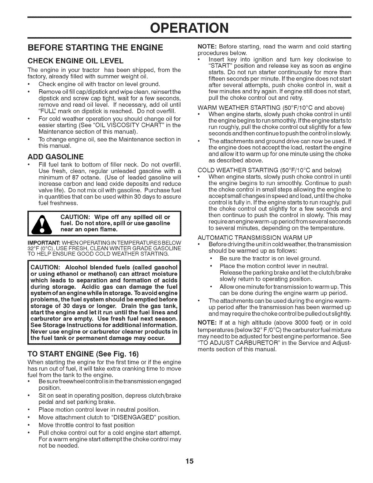
CAUTION: Wipe off any spilled oil or
fuel. Do not store, spill or use gasoline
near an open flame.
iMPORTANT: WHEN OPERATING IN TEMPERATURES BELOW
32°F (0°C), USE FRESH, CLEAN WINTER GRADE GASOLINE
TO HELP ENSURE GOOD COLD WEATHER STARTING.
CAUTION: Alcohol blended fuels (called gasohol
or using ethanol or methanol) can attract moisture
which leads to separation and formation of acids
during storage. Acidic gas can damage the fuel
system of an enginewhile instorage. To avoid engine
problems, the fuel system should be emptied before
storage of 30 days or longer. Drain the gas tank,
start the engine and let it run until the fuel lines and
carburetor are empty. Use fresh fuel next season.
See Storage instructions for additional information.
Never use engine or carburetor cleaner products in
the fuel tank or permanent damage may occur.
TO START ENGINE (See Fig. 16)
When starting the engine for the first time or if the engine
has run out of fuel, it will take extra cranking time to move
fuel from the tank to the engine.
•Be sure freewheel control is in the transmission engaged
position.
•Sit on seat in operating position, depress clutch/brake
pedal and set parking brake.
•Place motion control lever in neutral position.
•Move attachment clutch to "DISENGAGED" position.
•Move throttle control to fast position
•Pull choke control out for a cold engine start attempt.
For a warm engine start attempt the choke control may
not be needed.
NOTE: Before starting, read the warm and cold starting
procedures below.
•Insert key into ignition and turn key clockwise to
"START" position and release key as soon as engine
starts. Do not run starter continuously for more than
fifteen seconds per minute. If the engine does not start
after several attempts, push choke control in, wait a
few minutes and try again. If engine still does not start,
pull the choke control out and retry.
WARM WEATHER STARTING (50°F/10°C and above)
•When engine starts, slowly push choke control in until
the engine begins to run smoothly. Ifthe engine starts to
run roughly, pull the choke control out slightly for afew
seconds and then continue to push the control inslowly.
• The attachments and ground drive can now be used. If
the engine does not accept the load, restart the engine
and allow it to warm up for one minute using the choke
as described above.
COLD WEATHER STARTING (50°F/10°C and below)
•When engine starts, slowly push choke control in until
the engine begins to run smoothly. Continue to push
the choke control in small steps allowing the engine to
accept small changes in speed and load, until the choke
control is fully in. If the engine starts to run roughly, pull
the choke control out slightly for a few seconds and
then continue to push the control in slowly. This may
require an engine warm-up period from several seconds
to several minutes, depending on the temperature.
AUTOMATIC TRANSMISSION WARM UP
•Before driving the unit in cold weather, the transmission
should be warmed up as follows:
• Be sure the tractor is on level ground.
• Place the motion control lever in neutral.
Release the parking brake and let the clutch/brake
slowly return to operating position.
• Allow one minute for transmission to warm up. This
can be done during the engine warm up period.
• The attachments can be used during the engine warm-
up period after the transmission has been warmed up
and may require the choke control be pulled out slightly.
NOTE: If at a high altitude (above 3000 feet) or in cold
temperatures (below 32° F/0°C) the carburetor fuel mixture
may need to be adjusted for best engine performance. See
"TO ADJUST CARBURETOR" in the Service and Adjust-
ments section of this manual.
15

OPERATION
PURGE TRANSMISSION
CAUTION'Never engage or disengage
&
I freewheel lever whilethe engine is running.
To ensure proper operation and performance, it is recom-
mended that the transmission be purged before operating
tractor for the first time. This procedure will remove any
trapped air inside the transmission which may have devel-
oped during shipping of your tractor.
iMPORTANT: SHOULD YOUR TRANSMISSION REQUIRE
REMOVAL FOR SERVICE OR REPLACEMENT, IT SHOULD
BE PURGEDAFTER REINSTALLATIONBEFOREOPERATING
THE TRACTOR.
1. Place tractor safely on a level surface - that is clear
and open - with engine off and parking brake set.
2. Disengage transmission by placing freewheel control
in freewheeling position (See "TO TRANSPORT" in
this section of manual).
3. Sitting in the tractor seat, start engine. After the engine
is running, move throttle control to slow position. With
motion control lever in neutral position, slowly disengage
clutch/brake pedal.
CAUTION _=me, during step 4, there
A
I may be movement of the drive wheels.
4. Move motion control lever to full forward position and
hold for five (5) seconds. Move lever to full reverse
position and hold for five (5) seconds. Repeat this
procedure three (3) times.
5. Move motion control lever to neutral position. Shut- off
engine and set parking brake.
6. Engage transmission by placing freewheel control in
engaged position (See "TO TRANSPORT" in this sec-
tion of manual).
7. Sitting inthe tractor seat, start engine. After the engine
is running, move throttle control to half (1/2) speed.
With motion control lever in neutral position, slowly
disengage clutch/brake pedal.
8. Slowly move motion control lever forward, after the
tractor moves approximately five (5) feet, slowly move
motion control lever to reverse position. After the trac-
tor moves approximately five (5) feet return the motion
control lever to the neutral position. Repeat this proce-
dure with the motion control lever three (3) times.
Your transmission is now purged and now ready for normal
operation.
MOWING TIPS
• Tire chains cannot be used when the mower housing
is attached to tractor.
• Mower should be properly leveled for best mowing
performance. See "TO LEVEL MOWER HOUSING"
in the Service and Adjustments section of this manual.
• The left hand side ofmower should be used for trimming.
• Drive so that clippings are discharged onto the area
that has been cut. Have the cut area to the right of
the tractor. This will result in a more even distribution
of clippings and more uniform cutting.
• When mowing large areas, start by turning to the right
so that clippings will discharge away from shrubs,
fences, driveways, etc. After one or two rounds, mow
in the opposite direction making left hand turns until
finished (See Fig. 26).
,
}=
Fig. 26
• If grass is extremely tall, it should be mowed twice to
reduce load and possible fire hazard from dried clip-
pings. Make first cut relatively high; the second to the
desired height.
• Do not mow grass when it is wet. Wet grass will plug
mower and leave undesirable clumps. Allow grass to
dry before mowing.
• Always operate engine at full throttle when mow=
ing to assure better mowing performance and proper
discharge of material. Regulate ground speed by
selecting a low enough gear to give the mower cutting
performance as well as the quality of cut desired.
• When operating attachments, select a ground speed
that will suit the terrain and give best performance of
the attachment being used.
16
MAINTENANCE
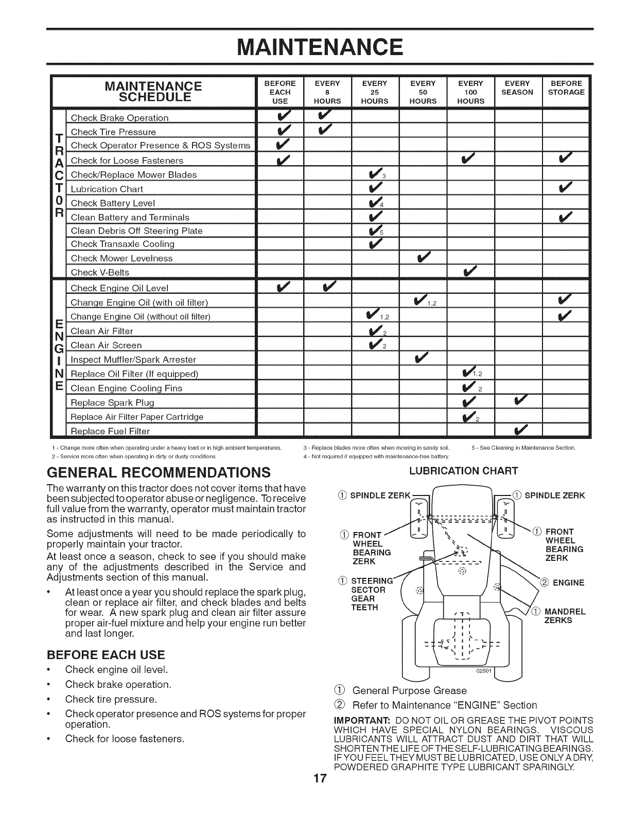
MAINTENANCE
SCHEDULE
Check Brake Operation
Check Tire Pressure
T Check Operator Presence & ROS Systems
ACheck for Loose Fasteners
CCheck/Replace Mower Blades
TLubrication Chart
0 Check Battery Level
R Clean Battery and Terminals
Clean Debris Off Steering Plate
Check Transaxle Cooling
Check Mower Levelness
Check V-Belts
Check Engine Oil Level
Change Enqine Oil (with oil filter)
Change Engine Oil (without oil filter)
E Clean Air Filter
G Clean Air Screen
I Inspect Muffler/Spark Attester
N Replace Oil Filter (if equipped)
E Clean Engine Cooling Fins
Replace Spark Plug
Replace Air Filter Paper Cartridge
m R_lace Fuel Filter
BEFORE
EACH
USE
v"
v'
v"
v"
EVERY
8
HOURS
EVERY
25
HOURS
v"
_1,2
V"2
V'2
EVERY
50
HOURS
v'
_1,2
v"
_,,,,,...,=======.===
EVERY
100
HOURS
v'
v"
_,2
v"2
V'
EVERY
SEASON
v"
v'
BEFORE
STORAGE
v"
v'
V'
v'
1 - Change more often when operating under a heavy load or in high ambient temperatures.
2 - Service more often when operating in dirty or dusty conditions.
GENERAL RECOMMENDATIONS
The warranty on this tractor does not cover items that have
been subjected to operator abuse or negligence. To receive
full value from the warranty, operator must maintain tractor
as instructed in this manual.
Some adjustments will need to be made periodically to
properly maintain your tractor.
At least once a season, check to see if you should make
any of the adjustments described in the Service and
Adjustments section of this manual.
• At least once a year you should replace the spark plug,
clean or replace air filter, and check blades and belts
for wear. A new spark plug and clean air filter assure
proper air-fuel mixture and help your engine run better
and last longer.
3 - Replace blades more often when mowing in sandy soil. 5 - See Cleaning in Maintenance Section.
4 - Not required if equipped with maintenance-free battery.
LUBRICATION CHART
(_ SPINDLE ZERK =SPINDLE ZERK
(_ FRONT FRONT
WHEEL WHEEL
BEARING BEARING
ZERK ZERK
SECTOR
GEAR
TEETH
ENGINE
MANDREL
ZERKS
BEFORE EACH USE
Check engine oil level.
•Check brake operation.
Check tire pressure.
•Check operator presence and ROS systems for proper
operation.
Check for loose fasteners.
17
02501
(_ General Purpose Grease
(_ Refer to Maintenance "ENGINE" Section
IMPORTANT: DO NOT OIL OR GREASE THE PIVOT POINTS
WHICH HAVE SPECIAL NYLON BEARINGS. VISCOUS
LUBRICANTS WILL ATTRACT DUST AND DIRT THAT WILL
SHORTEN THE LIFE OFTHE SELF-LUBRICATING BEARINGS.
IFYOU FEELTHEY MUST BE LUBRICATED, USE ONLYA DRY,
POWDERED GRAPHITE TYPE LUBRICANT SPARINGLY.

MAINTENANCE
TRACTOR
Always observe safety rules when performing any
maintenance.
BRAKE OPERATION
If tractor requires more than five (5) feet to stop at highest
speed in highest gear on a level, dry concrete or paved
surface, then brake must be checked and adjusted. (See
"TO CHECK BRAKE" in the Service and Adjustments
section of this manual).
TIRES
• Maintain proper air pressure in all tires (See the sides
of tires for proper PSI).
• Keep tires free of gasoline, oil, or insect control
chemicals which can harm rubber.
• Avoid stumps, stones, deep ruts, sharp objects and
other hazards that may cause tire damage.
NOTE: To seal tire punctures and prevent flat tires due
to slow leaks, tire sealant may be purchased from your
local parts dealer. Tire sealant also prevents tire dry rot
and corrosion.
OPERATOR PRESENCE SYSTEM AND REVERSE
OPERATION SYSTEM (ROS) (See Fig. 27)
Be sure operator presence and reverse operation systems
are working properly. If your tractor does not function as
described, repair the problem immediately.
• The engine should not start unless the brake pedal is
fully depressed, and the attachment clutch control is
in the disengaged position.
CHECK OPERATOR PRESENCE SYSTEM
• When the engine is running, any attempt bythe operator
to leave the seat without first setting the parking brake
should shut off the engine.
• When the engine is running and the attachment clutch
is engaged, any attempt by the operator to leave the
seat should shut off the engine.
• The attachment clutch should never operate unless
the operator is in the seat.
CHECK REVERSE OPERATION (ROS) SYSTEM
•When the engine is running with the ignition switch in
the engine "ON" position and the attachment clutch
engaged, any attempt by the operator to shift into
reverse should shut off the engine.
•When the engine is running with the ignition switch
in the ROS "ON" position and the attachment clutch
engaged, any attempt by the operator to shift into
reverse should NOT shut off the engine.
ROS "ON"
POSITION ENGINE "ON" POSITION
(NORMAL OPERATING)
Fig. 27
BLADE CARE
For best results mower blades must be kept sharp. Replace
bent or damaged blades.
CAUTION: Use onlya replacement blade ap=
proved by the manufacturer of your tractor.
Using ablade not approved by the manu=
facturer of your tractor is hazardous, could
damage your tractor and void your warranty.
BLADE REMOVAL (See Fig. 28)
• Raise mower to highest position to allow access to
blades.
NOTE: Protect your hands with gloves and/or wrap blade
with heavy cloth.
• Remove blade bolt by turning counterclockwise.
• Install new or resharpened blade with stamped "THIS
SIDE UP" facing deck and mandrel assembly.
iMPORTANT:TO ENSURE PROPERASSEMBLY,CENTER
HOLE IN BLADE MUST ALIGN WITH STAR ON MANDREL
ASSEMBLY.
• Install and tighten blade bolt securely (45-55 Ft. Lbs.
torque).
IMPORTANT: SPECIAL BLADE BOLT HEATTREATED.
MANDREL
BLADE
BLADE BOLT,
(SPECIAL)
18
CENTER HOLE
Fig. 28
BATTERY
Your tractor has a battery charging system which is sufficient
for normal use. However, periodic charging of the battery
with an automotive charger will extend its life.
• Keep battery and terminals clean.
• Keep battery bolts tight.
• Keep small vent holes open.
• Recharge at 6-10 amperes for 1 hour.
NOTE: The original equipment battery on your tractor ismain-
tenance free. Do not attempt to open or remove caps or cov-
ers. Adding or checking level of electrolyte is not necessary.
TO CLEAN BATTERY AND TERMINALS
Corrosion and dirt on the battery and terminals can cause
the battery to "leak" power.
• Raise hood.
• Disconnect BLACK battery cable first then RED bat-
tery cable and remove battery from tractor.
• Rinse the battery with plain water and dry.
• Clean terminals and battery cable ends with wire brush
until bright.
• Coat terminals with grease or petroleum jelly.
• Reinstall battery (See "REPLACING BATTERY" inthe
SERVICEAND ADJUSTMENTS section ofthismanual).
MAINTENANCE
V=BELTS
Check V-belts for deterioration and wear after 100 hours
of operation and replace if necessary. The belts are not
adjustable. Replace belts if they begin to slip from wear.
TRANSAXLE COOLING
The transmission fan and cooling fins should be kept clean
to assure proper cooling.
Do not attempt to clean fan or transmission while engine
is running or while the transmission is hot. To prevent pos-
sible damage to seals, do not use high pressure water or
steam to clean transaxle.
Inspect cooling fan to be sure fan blades are intact and
clean.
Inspect cooling fins for dirt, grass clippings and other
materials. To prevent damage to seals, do not use
compressed air or high pressure sprayer to clean
cooling fins.
TRANSAXLE PUMP FLUID
The transaxle was sealed at the factory and fluid mainte-
nance is not required for the life of the transaxle. Should
the transaxle ever leak or require servicing, contact your
nearest authorized service center/department.
ENGINE
LUBRICATION
Only use high quality detergent oil rated with API service
classification SG-SL. Select the oil's SAE viscosity grade
according to your expected operating temperature.
SAE VISCOSITY GRADES
mE/
F -20 0 30 32 40 60 80 100
C -30 -2; -1; ; 1'0 20 10 4;
TEMPERATURE RANGE ANTICIPATED BEFORE NEXT OIL CHANGE
NOTE: Although multi-viscosity oils (5W30, 10W30 etc.
improve starting in cold weather, they will result in increased
oil consumption when used above 32°F/0°C. Check your
engine oil level more frequently to avoid possible engine
damage from running low on oil.
Change the oil after every 50 hours of operation or at least
once a year if the tractor is not used for 50 hours in one year.
Check the crankcase oil level before starting the engine
and after each eight (8) hours of operation. Tighten oil fill
cap/dipstick securely each time you check the oil level.
ENGINE COOLING SYSTEM
To ensure proper cooling, make sure the grass screen,
cooling fins, and other external surfaces of the engine are
kept clean at all times.
Every 100 hours of operation (more often under extremely
dusty, dirty conditions), remove the blower housing and
other cooling shrouds. Clean the cooling fins and external
surfaces as necessary. Ensure the cooling shrouds are
reinstalled.
NOTE: Operating the engine with a blocked grass screen,
dirty orplugged cooling fins, and/or cooling shrouds removed
will cause engine damage due to overheating.
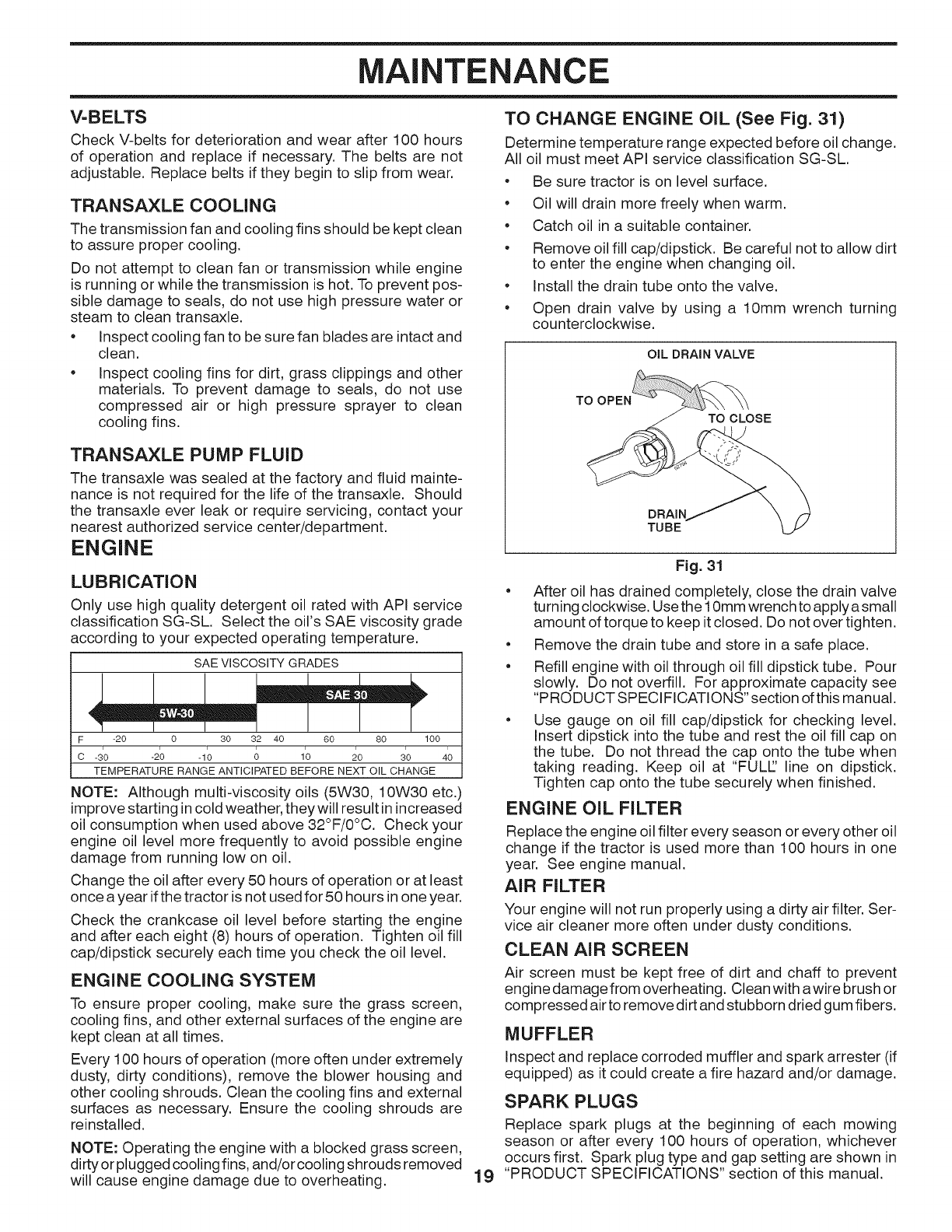
TO CHANGE ENGINE OIL (See Fig. 31)
Determine temperature range expected before oil change.
All oil must meet API service classification SG-SL.
* Be sure tractor is on level surface.
* Oil will drain more freely when warm.
* Catch oil in a suitable container.
* Remove oil fill cap/dipstick. Be careful not to allow dirt
to enter the engine when changing oil.
* Install the drain tube onto the valve.
* Open drain valve by using a 10mm wrench turning
counterclockwise.
OIL DRAIN VALVE
TO CLOSE
DRAIN
TUBE
19
Fig. 31
* After oil has drained completely, close the drain valve
turning clockwise. Use the 10mm wrench toapply a small
amount of torque to keep it closed. Do not over tighten.
* Remove the drain tube and store in a safe place.
* Refill engine with oil through oil fill dipstick tube. Pour
slowly. Do not overfill. For approximate capacity see
"PRODUCT SPECIFICATIONS" section of this manual.
Use gauge on oil fill cap/dipstick for checking level.
Insert dipstick into the tube and rest the oil fill cap on
the tube. Do not thread the cap onto the tube when
taking reading. Keep oil at "FULL' line on dipstick.
Tighten cap onto the tube securely when finished.
ENGINE OIL FILTER
Replace the engine oil filter every season or every other oil
change if the tractor is used more than 100 hours in one
year. See engine manual.
AIR FILTER
Your engine will not run properly using a dirty air filter. Ser-
vice air cleaner more often under dusty conditions.
CLEAN AIR SCREEN
Air screen must be kept free of dirt and chaff to prevent
engine damage from overheating. Clean with awire brush or
compressed airto remove dirt and stubborn dried gum fibers.
MUFFLER
Inspect and replace corroded muffler and spark arrester (if
equipped) as it could create a fire hazard and/or damage.
SPARK PLUGS
Replace spark plugs at the beginning of each mowing
season or after every 100 hours of operation, whichever
occurs first. Spark plug type and gap setting are shown in
"PRODUCT SPECIFICATIONS" section of this manual.
MAINTENANCE
IN=LINE FUEL FILTER (See Fig. 32)
The fuel filter should be replaced once each season. Iffuel
filter becomes clogged, obstructing fuel flow to carburetor,
replacement is required.
• With engine cool, removefilter and plug fuel linesections.
• Place new fuel filter in position in fuel line with arrow
pointing towards carburetor.
• Be sure there are no fuel line leaks and clamps are
properly positioned.
• Immediately wipe up any spilled gasoline.
CLAMP-,_
CLAMP
FUEL FILTER
Fig. 32
CLEANING
• Clean engine, battery, seat, finish, etc. of all foreign
matter.
• Clean debris from steering plate. Debris can restrict
clutch/brake pedal shaft movement, causing belt slip
and loss of drive.
_CAUTION: Avoid all pinch points and
movable parts (See Fig. 33)
MOWER NOT SHOWN
Fig. 33
• Keep finished surfaces and wheels free of all gasoline,
oil, etc.
• Protect painted surfaces with automotive type wax.
We do not recommend using a garden hose or pressure
washer to clean your tractor unless the engine and trans-
mission are covered to keep water out. Water in engine or
transmission will shorten the useful life of your tractor. Use
compressed air or a leaf blower to remove grass, leaves
and trash from tractor and mower.
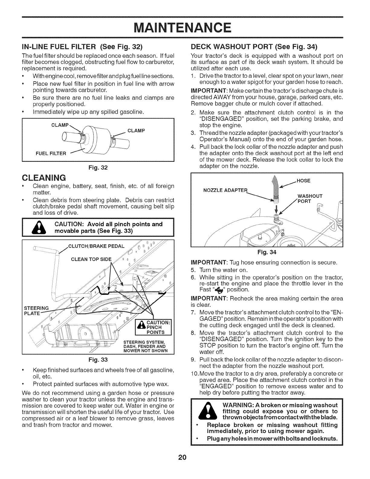
DECK WASHOUT PORT (See Fig. 34)
Your tractor's deck is equipped with a washout port on
its surface as part of its deck wash system. It should be
utilized after each use.
1. Drive the tractor to a level, clear spot on your lawn, near
enough to a water spigot for your garden hose to reach.
IMPORTANT: Make certain the tractor's discharge chute is
directed AWAY from your house, garage, parked cars, etc.
Remove bagger chute or mulch cover if attached.
2. Make sure the attachment clutch control is in the
"DISENGAGED" position, set the parking brake, and
stop the engine.
3. Thread the nozzle adapter (packagedwith your tractor's
Operator's Manual) onto the end of your garden hose.
4. Pull backthe lock collar of the nozzle adapter and push
the adapter onto the deck washout port at the left end
of the mower deck. Release the lock collar to lock the
adapter on the nozzle.
NOZZLE ADAPTER
k.,.tI HOSE
WASHOUT
Fig. 34
IMPORTANT: Tug hose ensuring connection is secure.
5. Turn the water on.
6. While sitting in the operator's position on the tractor,
re-start the engine and place the throttle lever in the
Fast "'_l(' position.
IMPORTANT: Recheck the area making certain the area
is clear.
7. Move the tractor's attachment clutch control to the "EN-
GAGED" position. Remain in the operator's position with
the cutting deck engaged until the deck is cleaned.
8. Move the tractor's attachment clutch control to the
"DISENGAGED" position. Turn the ignition key to the
STOP position to turn the tractor's engine off. Turn the
water off.
9. Pull back the lock collar of the nozzle adapter to discon-
nect the adapter from the nozzle washout port.
10. Move the tractor to a dry area, preferably a concrete or
paved area. Place the attachment clutch control in the
"ENGAGED" position to remove excess water and to
help dry before putting the tractor away.
WARNING: A broken or missing washout
fitting could expose you or others to
thrown objects from contact withthe blade.
•Replace broken or missing washout fitting
immediately, prior to using mower again.
• Plug any holes in mower with bolts and Iocknuts.
2O
SERVICE AND ADJUSTMENTS
o
o
o
WARNING: TO AVOID SERIOUS iNJURY, BEFORE PERFORMING ANY SERVICE OR ADJUSTMENTS:
Depress brake pedal fully and set parking brake.
Ensure transa×le is in the neutral position.
Place attachment clutch in "DISENGAGED" position.
=Turn ignition key to "STOP" and remove key.
= Ensure the blades and all moving parts have completely stopped.
=Disconnect spark plug wire from spark plug and place wire where it cannot come in contact with plug.
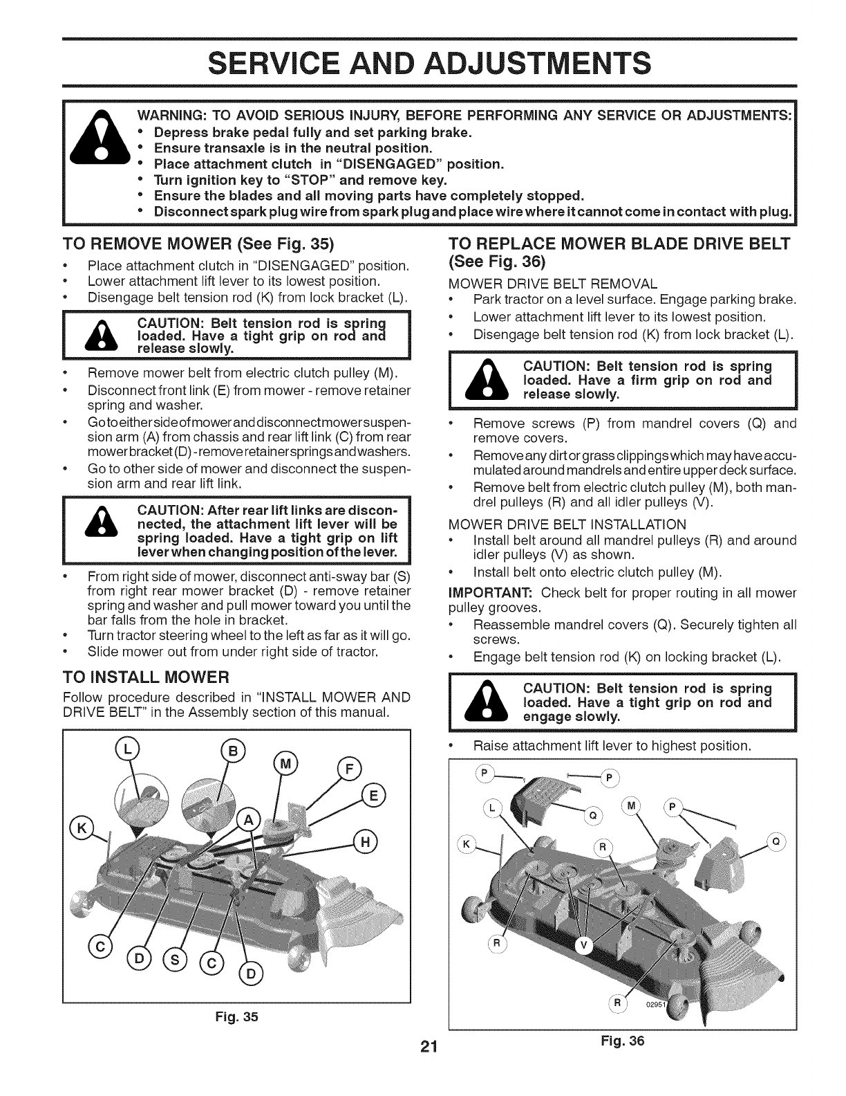
TO REMOVE MOWER (See Fig. 35)
• Place attachment clutch in "DISENGAGED" position.
• Lower attachment lift lever to its lowest position.
• Disengage belt tension rod (K) from lock bracket (L).
loaded. Have a tight grip on rodand
release slowly.
• Remove mower belt from electric clutch pulley (M).
• Disconnect front link (E) from mower - remove retainer
spring and washer.
• Goto eitherside ofmower anddisconnect mowersuspen-
sion arm (A) from chassis and rear lift link (0) from rear
mower bracket (D)- remove retainersprings andwashers.
• Go to other side of mower and disconnect the suspen-
sion arm and rear lift link.
CAUTION: After rear lift links are discon=
nected, the attachment lift lever will be
spring loaded. Have a tight grip on lift
lever when changing position of the lever.
From right side of mower, disconnect anti-sway bar (S)
from right rear mower bracket (D) - remove retainer
spring and washer and pull mower toward you until the
bar falls from the hole in bracket.
Turn tractor steering wheel to the left as far as itwill go.
Slide mower out from under right side of tractor.
TO INSTALL MOWER
Follow procedure described in "INSTALL MOWER AND
DRIVE BELT" in the Assembly section of this manual.
Fig. 35
TO REPLACE MOWER BLADE DRIVE BELT
(See Fig. 36)
MOWER DRIVE BELT REMOVAL
•Park tractor on a level surface. Engage parking brake.
•Lower attachment lift lever to its lowest position.
•Disengage belt tension rod (K) from lock bracket (L).
_CAUTION: Belt tension rod is springdBL
loaded. Have a firm grip on rod and
release slowly.
• Remove screws (P) from mandrel covers (Q) and
remove covers.
• Remove any dirt orgrass clippings which may have accu-
mulated around mandrels and entire upper decksurface.
• Remove belt from electric clutch pulley (M), both man-
drel pulleys (R) and all idler pulleys (V).
MOWER DRIVE BELT INSTALLATION
• Install belt around all mandrel pulleys (R) and around
idler pulleys (V) as shown.
• Install belt onto electric clutch pulley (M).
IMPORTANT: Check belt for proper routing in all mower
pulley grooves.
• Reassemble mandrel covers (Q). Securely tighten all
screws.
• Engage belt tension rod (K) on locking bracket (L).
CAUTION: Belt tension rod is spring
loaded. Have a tight grip on rod and
engage slowly.
• Raise attachment lift lever to highest position.
21 Fig. 36
SERVICE AND ADJUSTMENTS
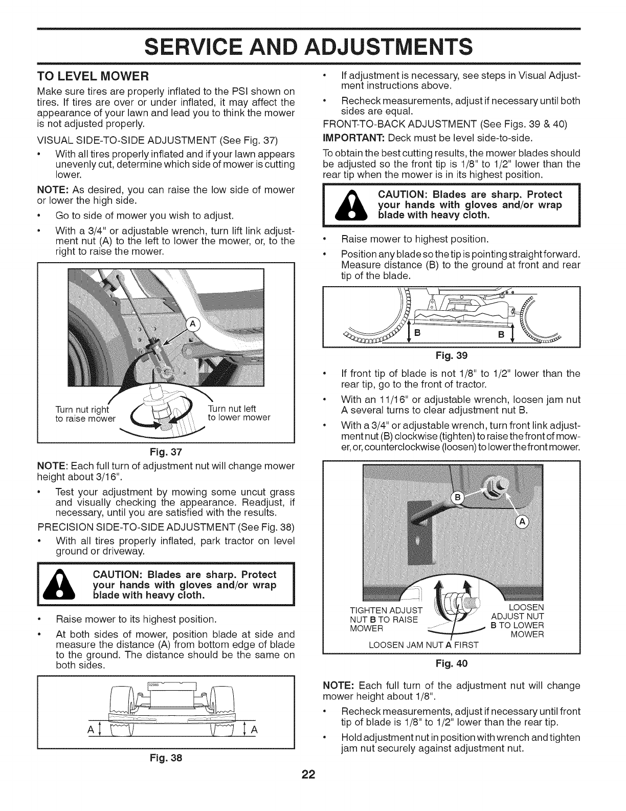
TO LEVEL MOWER
Make sure tires are properly inflated to the PSI shown on
tires. If tires are over or under inflated, it may affect the
appearance of your lawn and lead you to think the mower
is not adjusted properly.
VISUAL SIDE-TO-SIDE ADJUSTMENT (See Fig. 37)
• With all tires properly inflated and if your lawn appears
unevenly cut, determine which side of mower iscutting
lower.
NOTE: As desired, you can raise the low side of mower
or lower the high side.
• Go to side of mower you wish to adjust.
•With a 3/4" or adjustable wrench, turn lift link adjust-
ment nut (A) to the left to lower the mower, or, to the
right to raise the mower.
Turn nut right Turn nut left
to raise mower to lower mower
Fig. 37
NOTE: Each full turn of adjustment nut will change mower
height about 3/16".
• Test your adjustment by mowing some uncut grass
and visually checking the appearance. Readjust, if
necessary, until you are satisfied with the results.
PRECISION SIDE-TO-SIDE ADJUSTMENT (See Fig. 38)
• With all tires properly inflated, park tractor on level
ground or driveway.
i_ CAUTION: Blades are sharp. Protect
your hands with gloves and/or wrap
blade with heavy cloth.
e
e
Raise mower to its highest position.
At both sides of mower, position blade at side and
measure the distance (A) from bottom edge of blade
to the ground. The distance should be the same on
both sides.
Fig. 38
• If adjustment is necessary, see steps inVisual Adjust-
ment instructions above.
• Recheck measurements, adjust if necessary until both
sides are equal.
FRONT-TO-BACK ADJUSTMENT (See Figs. 39 & 40)
iMPORTANT: Deck must be level side-to-side.
To obtain the best cutting results, the mower blades should
be adjusted so the front tip is 1/8" to 1/2" lower than the
rear tip when the mower is in its highest position.
_CAUTION: Blades are sharp. Protect
your hands with gloves and/or wrap
blade with heavy cloth.
e
e
Raise mower to highest position.
Position any blade so the tip is pointing straightforward.
Measure distance (B) to the ground at front and rear
tip of the blade.
Fig. 39
If front tip of blade is not 1/8" to 1/2" lower than the
rear tip, go to the front of tractor.
With an 11/16" or adjustable wrench, loosen jam nut
A several turns to clear adjustment nut B.
With a 3/4" or adjustable wrench, turn front link adjust-
ment nut (B)clockwise (tighten) to raise the front of mow-
er,or, counterclockwise (loosen) to lower the front mower.
TIGHTEN ADJUST LOOSEN
NUT B TO RAISE ADJUST NUT
MOWER _/- .... B TO LOWER
MOWER
LOOSEN JAM NUTA FIRST
Fig. 40
NOTE: Each full turn of the adjustment nut will change
mower height about 1/8".
• Recheck measurements, adjust if necessary until front
tip of blade is 1/8" to 1/2" lower than the rear tip.
• Hold adjustment nut in position with wrench and tighten
jam nut securely against adjustment nut.
22
SERVICE AND ADJUSTMENTS
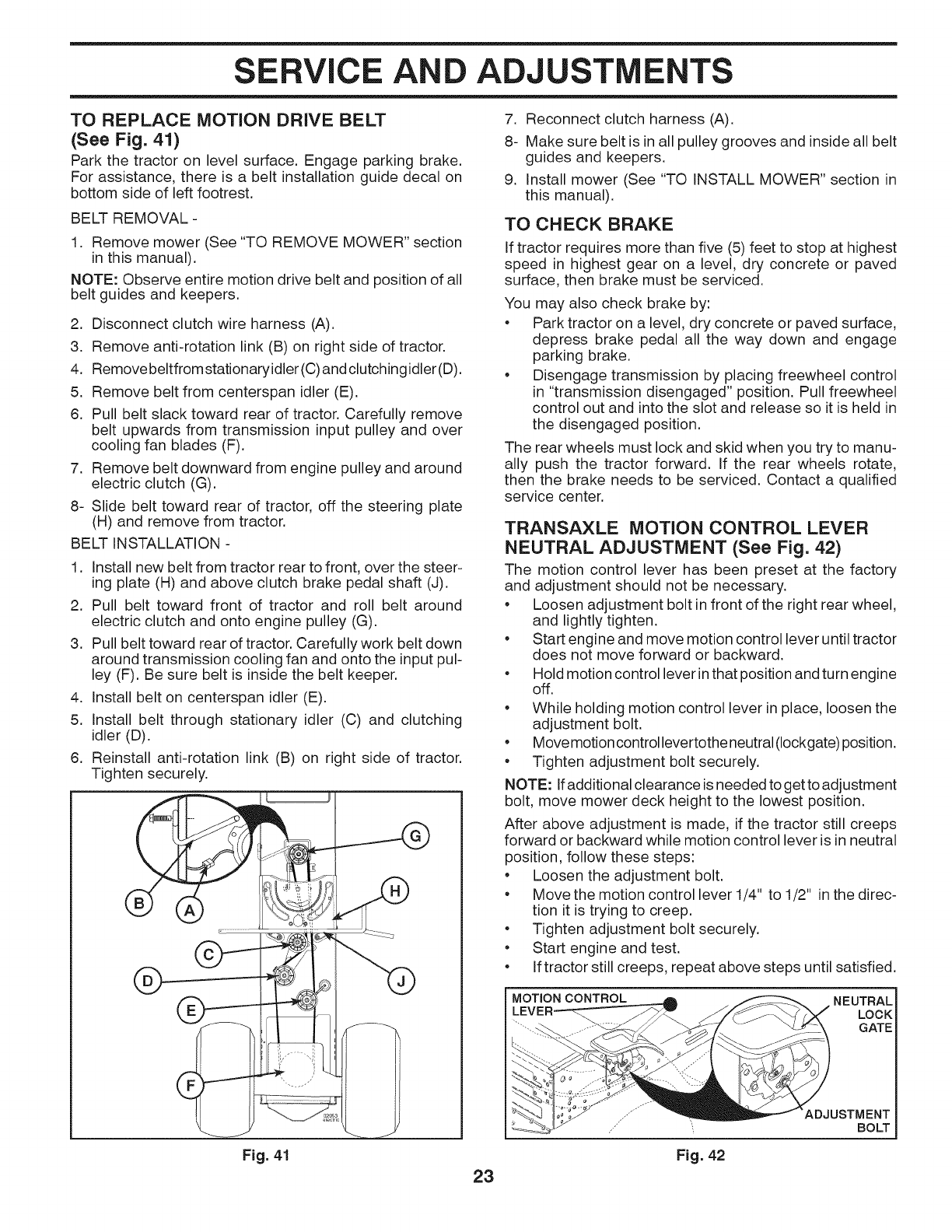
TO REPLACE MOTION DRIVE BELT
(See Fig. 41)
Park the tractor on level surface. Engage parking brake.
For assistance, there is a belt installation guide decal on
bottom side of left footrest.
BELT REMOVAL -
1. Remove mower (See "TO REMOVE MOWER" section
in this manual).
NOTE: Observe entire motion drive belt and position of all
belt guides and keepers.
2. Disconnect clutch wire harness (A).
3. Remove anti-rotation link (B) on right side of tractor.
4. Removebeltfromstationaryidler (C) andclutchingidler (D).
5. Remove belt from centerspan idler (E).
6. Pull belt slack toward rear of tractor. Carefully remove
belt upwards from transmission input pulley and over
cooling fan blades (F).
7. Remove belt downward from engine pulley and around
electric clutch (G).
8- Slide belt toward rear of tractor, off the steering plate
(H) and remove from tractor.
BELT INSTALLATION -
1. Install new belt from tractor rear to front, over the steer-
ing plate (H) and above clutch brake pedal shaft (J).
2. Pull belt toward front of tractor and roll belt around
electric clutch and onto engine pulley (G).
3. Pull belt toward rear of tractor. Carefully work belt down
around transmission cooling fan and onto the input pul-
ley (F). Be sure belt is inside the belt keeper.
4. Install belt on centerspan idler (E).
5. Install belt through stationary idler (C) and clutching
idler (D).
6. Reinstall anti-rotation link (B) on right side of tractor.
Tighten securely.
Fig. 41 23
7. Reconnect clutch harness (A).
8- Make sure belt is in all pulley grooves and inside all belt
guides and keepers.
9. Install mower (See "TO INSTALL MOWER" section in
this manual).
TO CHECK BRAKE
If tractor requires more than five (5) feet to stop at highest
speed in highest gear on a level, dry concrete or paved
surface, then brake must be serviced.
You may also check brake by:
•Park tractor on a level, dry concrete or paved surface,
depress brake pedal all the way down and engage
parking brake.
•Disengage transmission by placing freewheel control
in "transmission disengaged" position. Pull freewheel
control out and into the slot and release so it is held in
the disengaged position.
The rear wheels must lock and skid when you try to manu-
ally push the tractor forward. If the rear wheels rotate,
then the brake needs to be serviced. Contact a qualified
service center.
TRANSAXLE MOTION CONTROL LEVER
NEUTRAL ADJUSTMENT (See Fig. 42)
The motion control lever has been preset at the factory
and adjustment should not be necessary.
•Loosen adjustment bolt infront of the right rear wheel,
and lightly tighten.
•Start engine and move motion control lever until tractor
does not move forward or backward.
•Hold motion control lever in that position and turn engine
off.
•While holding motion control lever in place, loosen the
adjustment bolt.
•Move motion control levertothe neutral (Iockgate) position.
•Tighten adjustment bolt securely.
NOTE: Ifadditional clearance is needed to get to adjustment
bolt, move mower deck height to the lowest position.
After above adjustment is made, if the tractor still creeps
forward or backward while motion control lever is in neutral
position, follow these steps:
•Loosen the adjustment bolt.
•Move the motion control lever 1/4" to 1/2" inthe direc-
tion it is trying to creep.
•Tighten adjustment bolt securely.
•Start engine and test.
•If tractor still creeps, repeat above steps until satisfied.
MOTION CONTROL NEUTRAL
LOCK
GATE
Fig. 42
ADJUSTMENT
BOLT
SERVICE AND ADJUSTMENTS
FRONT WHEEL TOE-IN/CAMBER
Your new tractor front wheel toe-in and camber is set at the
factory and is normal. The front wheel toe-in and camber
are not adjustable. If damage has occurred to affect the
factory set front wheel toe-in or camber, contact a qualified
service center.
TO REMOVE WHEEL FOR REPAIRS
(See Fig. 43)
• Block up axle securely.
• Remove axle cover, retaining ring and washers to allow
wheel removal (rear wheel contains a square key - Do
not lose).
• Repair tire and reassemble.
• On rear wheels only: align grooves in rear wheel hub
and axle. Insert square key.
• Replace washers and snap retaining ring securely in
axle groove.
• Replace axle cover.
NOTE: To seal tire punctures and prevent flat tires due
to slow leaks, tire sealant may be purchased from your
local parts dealer. Tire sealant also prevents tire dry rot
and corrosion.
WASHERS
RETAINING
RING X
AXLE C_\
SQUARE KEY (REAR=.__.__._._ _1
WHEEL ONLY)
Fig. 43
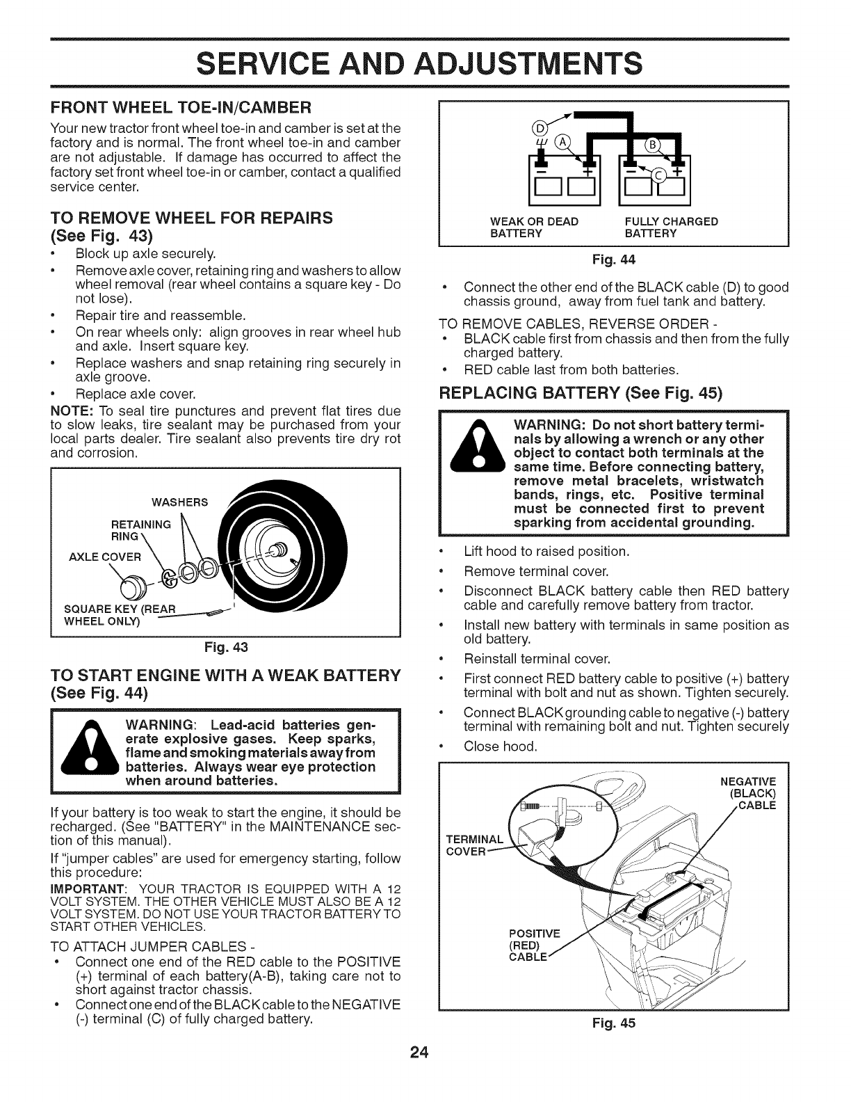
TO START ENGINE WITH A WEAK BATTERY
(See Fig. 44)
WARNING: Lead=acid batteries gen=
crate explosive gases. Keep sparks,
flame and smoking materials away from
batteries. Always wear eye protection
when around batteries.
If your battery is too weak to start the engine, it should be
recharged. (See "BATTERY" in the MAINTENANCE sec-
tion of this manual).
If "jumper cables" are used for emergency starting, follow
this procedure:
IMPORTANT: YOUR TRACTOR IS EQUIPPED WITH A 12
VOLT SYSTEM. THE OTHER VEHICLE MUST ALSO BE A 12
VOLT SYSTEM. DO NOT USE YOUR TRACTOR BATTERYTO
START OTHER VEHICLES.
TO ATTACH JUMPER CABLES -
•Connect one end of the RED cable to the POSITIVE
(+) terminal of each battery(A-B), taking care not to
short against tractor chassis.
• Connect one end of the BLACKcable to the NEGATIVE
(-) terminal (C) of fully charged battery.
WEAK OR DEAD
BATTERY FULLY CHARGED
BATTERY
Fig. 44
• Connect the other end of the BLACK cable (D) to good
chassis ground, away from fuel tank and battery.
TO REMOVE CABLES, REVERSE ORDER -
•BLACK cable first from chassis and then from the fully
charged battery.
• RED cable last from both batteries.
REPLACING BATTERY (See Fig. 45)
_ WARNING: Do not short batterytermi-
nals by allowing a wrench or any other
object to contact both terminals at the
same time. Before connecting battery,
remove metal bracelets, wristwatch
bands, rings, etc. Positive terminal
must be connected first to prevent
sparking from accidental grounding.
• Lift hood to raised position.
• Remove terminal cover.
• Disconnect BLACK battery cable then RED battery
cable and carefully remove battery from tractor.
• Install new battery with terminals in same position as
old battery.
• Reinstall terminal cover.
• First connect RED battery cable to positive (+) battery
terminal with bolt and nut as shown. Tighten securely.
• Connect BLACKgrounding cable to negative (-) battery
terminal with remaining bolt and nut. Tighten securely
• Close hood.
NEGATIVE
(BLACK)
TERMINAL
24
Fig. 45
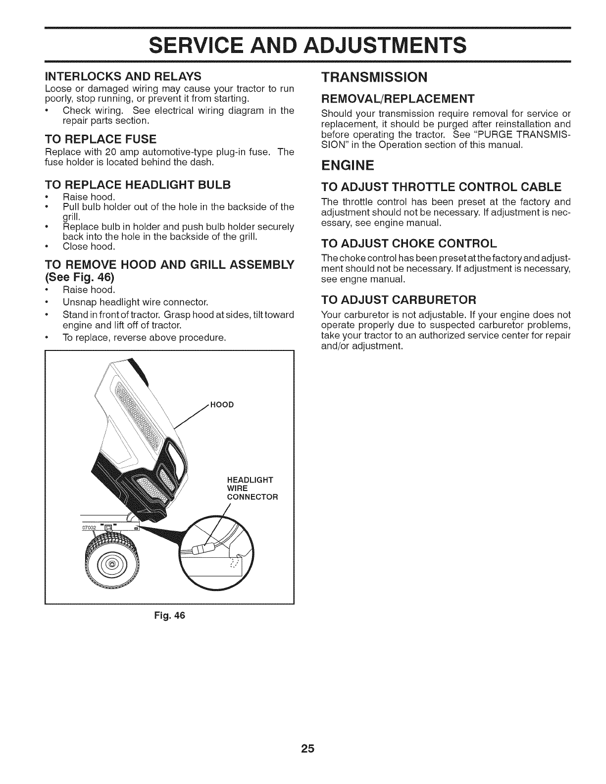
SERVICE AND ADJUSTMENTS
iNTERLOCKS AND RELAYS
Loose or damaged wiring may cause your tractor to run
poorly, stop running, or prevent it from starting.
Check wiring. See electrical wiring diagram in the
repair parts section.
TO REPLACE FUSE
Replace with 20 amp automotive-type plug-in fuse. The
fuse holder is located behind the dash.
TO REPLACE HEADLIGHT BULB
Raise hood.
• Pull bulb holder out of the hole in the backside of the
grill.
• Replace bulb in holder and push bulb holder securely
back into the hole in the backside of the grill.
• Close hood.
TO REMOVE HOOD AND GRILL ASSEMBLY
(See Fig. 46)
• Raise hood.
• Unsnap headlight wire connector.
• Stand in front of tractor. Grasp hood at sides, tilt toward
engine and lift off of tractor.
• To replace, reverse above procedure.
TRANSMISSION
REMOVAL/REPLACEMENT
Should your transmission require removal for service or
replacement, it should be purged after reinstallation and
before operating the tractor. See "PURGE TRANSMIS-
SION" in the Operation section of this manual.
ENGINE
TO ADJUST THROTTLE CONTROL CABLE
The throttle control has been preset at the factory and
adjustment should not be necessary. If adjustment is nec-
essary, see engine manual.
TO ADJUST CHOKE CONTROL
The choke control has been preset at the factory and adjust-
ment should not be necessary. If adjustment is necessary,
see engne manual.
TO ADJUST CARBURETOR
Your carburetor is not adjustable. If your engine does not
operate properly due to suspected carburetor problems,
take your tractor to an authorized service center for repair
and/or adjustment.
HEADLIGHT
WIRE
CONNECTOR
Fig. 46
25
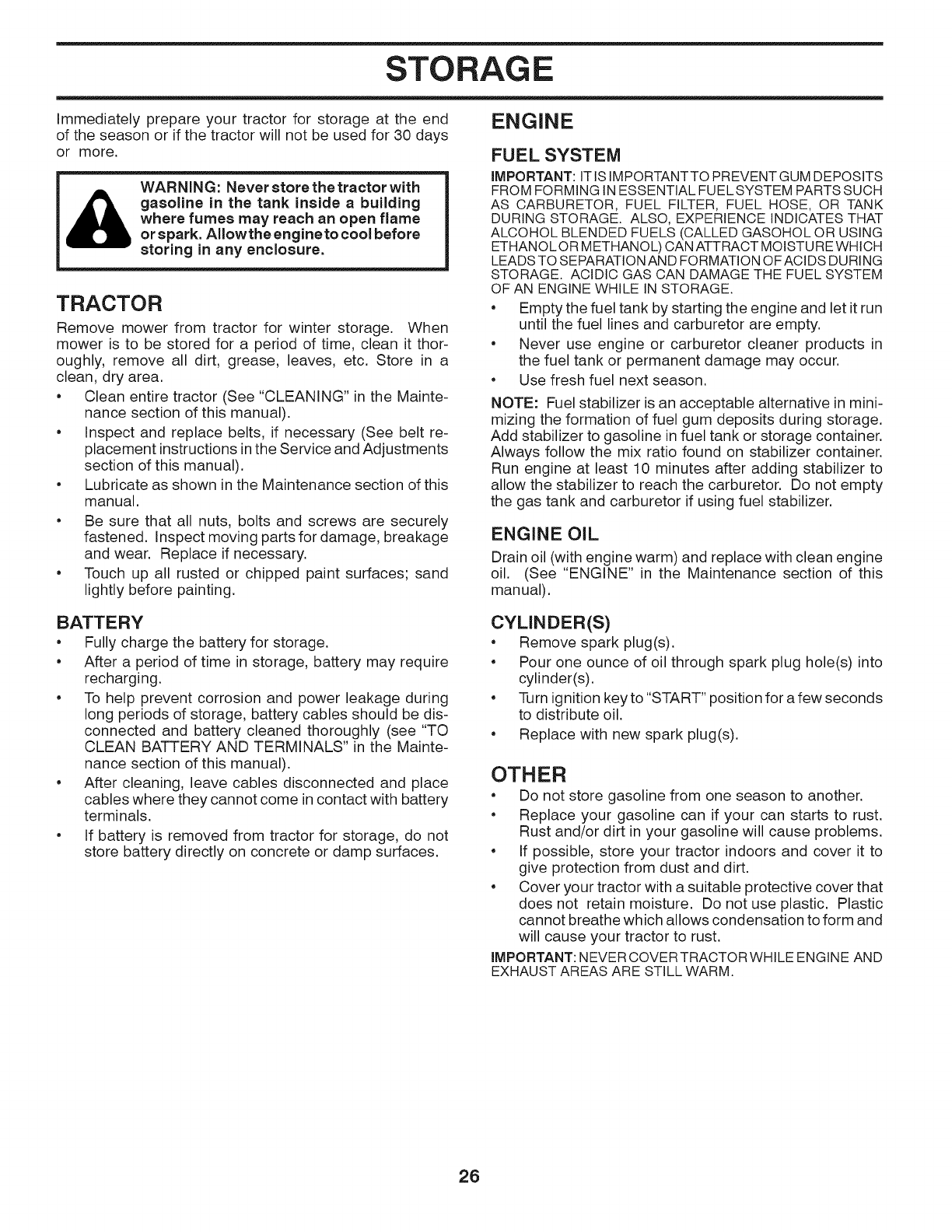
STORAGE
Immediately prepare your tractor for storage at the end
of the season or if the tractor will not be used for 30 days
or more.
WARNIN G: Never store the tractor with
gasoline in the tank inside a building
where fumes may reach an open flame
or spark. Allowthe engine to cool before
storing in any enclosure.
TRACTOR
Remove mower from tractor for winter storage. When
mower is to be stored for a period of time, clean it thor-
oughly, remove all dirt, grease, leaves, etc. Store in a
clean, dry area.
• Clean entire tractor (See "CLEANING" in the Mainte-
nance section of this manual).
• Inspect and replace belts, if necessary (See belt re-
placement instructions inthe Service and Adjustments
section of this manual).
• Lubricate as shown in the Maintenance section of this
manual.
• Be sure that all nuts, bolts and screws are securely
fastened. Inspect moving parts for damage, breakage
and wear. Replace if necessary.
• Touch up all rusted or chipped paint surfaces; sand
lightly before painting.
ENGINE
FUEL SYSTEM
IMPORTANT: IT IS IMPORTANTTO PREVENT GUM DEPOSITS
FROM FORMING IN ESSENTIAL FUELSYSTEM PARTS SUCH
AS CARBURETOR, FUEL FILTER, FUEL HOSE, OR TANK
DURING STORAGE. ALSO, EXPERIENCE INDICATES THAT
ALCOHOL BLENDED FUELS (CALLED GASOHOL OR USING
ETHANOLOR METHANOL) CAN ATTRACT MOISTURE WHICH
LEADS TO SEPARATION AND FORMATION OFACIDS DURING
STORAGE. ACIDIC GAS CAN DAMAGE THE FUEL SYSTEM
OF AN ENGINE WHILE IN STORAGE.
• Empty the fuel tank by starting the engine and let it run
until the fuel lines and carburetor are empty.
• Never use engine or carburetor cleaner products in
the fuel tank or permanent damage may occur.
• Use fresh fuel next season.
NOTE: Fuel stabilizer is an acceptable alternative in mini-
mizing the formation of fuel gum deposits during storage.
Add stabilizer to gasoline in fuel tank or storage container.
Always follow the mix ratio found on stabilizer container.
Run engine at least 10 minutes after adding stabilizer to
allow the stabilizer to reach the carburetor. Do not empty
the gas tank and carburetor if using fuel stabilizer.
ENGINE OiL
Drain oil (with engine warm) and replace with clean engine
oil. (See "ENGINE" in the Maintenance section of this
manual).
BATTERY
• Fully charge the battery for storage.
• After a period of time in storage, battery may require
recharging.
• To help prevent corrosion and power leakage during
long periods of storage, battery cables should be dis-
connected and battery cleaned thoroughly (see "TO
CLEAN BATTERY AND TERMINALS" in the Mainte-
nance section of this manual).
• After cleaning, leave cables disconnected and place
cables where they cannot come in contact with battery
terminals.
• If battery is removed from tractor for storage, do not
store battery directly on concrete or damp surfaces.
CYLINDER(S)
• Remove spark plug(s).
• Pour one ounce of oil through spark plug hole(s) into
cylinder(s).
• Turn ignition key to "START" position for a few seconds
to distribute oil.
• Replace with new spark plug(s).
OTHER
•Do not store gasoline from one season to another.
•Replace your gasoline can if your can starts to rust.
Rust and/or dirt in your gasoline will cause problems.
•If possible, store your tractor indoors and cover it to
give protection from dust and dirt.
•Cover your tractor with a suitable protective cover that
does not retain moisture. Do not use plastic. Plastic
cannot breathe which allows condensation to form and
will cause your tractor to rust.
IMPORTANT: NEVERCOVERTRACTORWHILE ENGINE AND
EXHAUST AREAS ARE STILL WARM.
26

TROU OOTI G
PROBLEM
Will not start
Hard to start
Engine will not
turn over
Engine clicks but
will not start
Loss of power
Excessive
vibration
CAUSE
1. Out of fuel.
CORRECTION
2. Engine not "CHOKED" properly.
3. Engine flooded.
4. Bad spark plug.
5. Dirty air filter.
6. Dirty fuel filter.
7. Water in fuel.
8.
9.
Loose or damaged wiring.
Carburetor out of adjustment.
10. Engine valves out of adjustment.
2. See "TO START ENGINE" in Operation section.
3. Wait several minutes before attempting to start.
4. Replace spark plug.
5. Clean/replace air filter.
6. Replace fuel filter.
7. Empty fuel tank and carburetor, refill tank with fresh
gasoline and replace fuel filter.
8. Check all wiring.
9. See "To Adjust Carburetor" in Service Adjustments
section.
10. Contact an authorized service center/department.
1. Dirty air filter.
2. Bad spark plug.
3. Weak or dead battery.
4. Dirty fuel filter.
5. Stale or dirty fuel.
6. Loose or damaged wiring.
7. Carburetor out of adjustment.
8. Engine valves out of adjustment.
1. Brake pedal not depressed.
2. Attachment clutch is engaged.
3. Weak or dead battery.
4. Blown fuse.
5. Corroded battery terminals.
6. Loose or damaged wiring.
7. Faulty ignition switch.
8. Faulty solenoid or starter.
9. Faulty operator presence switch(es).
1. Weak or dead battery.
2. Corroded battery terminals.
3. Loose or damaged wiring.
4. Faulty solenoid or starter.
1. Cutting too much grass/too fast.
2. Throttle in "CHOKE" position.
3. Build-up ofgrass, leaves, trash under mower.
4. Dirty air filter.
5. Low oil level/dirty oil.
6. Faulty spark plug.
7. Dirty fuel filter.
8. Stale or dirty fuel.
9. Water in fuel.
10. Spark plug wire loose.
11. Dirty engine air screen/fins.
12. Dirty/clogged muffler.
13. Loose or damaged wiring.
14. Carburetor out of adjustment.
15. Engine valves out of adjustment.
1. Worn, bent or loose blade.
2. Bent blade mandrel.
3. Loose/damaged part(s).
1. Clean/replace air filter.
2. Replace spark plug.
3. Recharge or replace battery.
4. Replace fuel filter.
5. Empty fuel tank and refill tank with fresh, clean gas.
6. Check all wiring.
7. See "To Adjust Carburetor" in Service Adjustments
section.
8. Contact an authorized service center/department.
1. Depress brake pedal.
2. Disengage attachment clutch.
3. Recharge or replace battery.
4. Replace fuse.
5. Clean battery terminals.
6. Check all wiring.
7. Check/replace ignition switch.
8. Check/replace solenoid or starter.
9. Contact an authorized service center/department.
1. Recharge or replace battery.
2. Clean battery terminals.
3. Check all wiring.
4. Check/replace solenoid or starter.
1. Raise cutting height/reduce speed.
2. Adjust throttle control.
3. Clean underside of mower housing.
4. Clean/replace air filter.
5. Check oil level/change oil.
6. Clean and regap or change spark plug.
7. Replace fuel filter.
8. Empty fuel tank and refill tank with fresh, clean gas.
9. Empty fuel tank and carburetor, refill tank with fresh
gasoline and replace fuel filter.
10. Connect and tighten spark plug wire.
11. Clean engine air screen/fins.
12. Clean/replace muffler.
13. Check all wiring.
14. See "To Adjust Carburetor" in Service Adjustments
15. Contact an authorized service center/department.
1. Replace blade. Tighten blade bolt.
2. Replace blade mandrel.
3. Tighten loose part(s). Replace damaged parts.
27

T BLESHOOTING
PROBLEM
Engine continues
to run when oper=
ator leaves seat
with attachment
clutch engaged
T
Poor cut - uneven
Mower blades wii[
not rotate
Poor grass
discharge
Headlight(s) not
working
(if so equipped)
Battery wii[ not
charge
Loss of drive
Engine "back=
fires" when turn=
ing engine "OFF"
Engine dies when
tractor is shifted
into reverse
CAUSE
1. Faulty operator-safety presence control
system.
CORRECTION
1. Check wiring, switches and connections. If not
corrected, contact an authorized service center/
department.
1. Worn, bent or loose blade.
2. Mower deck not level.
3. Buildup of grass, leaves, trash under mower.
4. Bent blade mandrel.
5. Clogged mower deck vent holes from
buildup of grass, leaves, and trash around
mandrels.
1. Obstruction in clutch mechanism.
2. Worn/damaged mower drive belt.
3. Frozen idler pulley.
4. Frozen blade mandrel.
1. Replace blade. Tighten blade bolt.
2. Level mower deck.
3. Clean underside of mower housing.
4. Replace blade mandrel.
5. Clean around mandrels to open vent holes.
1. Remove obstruction.
2. Replace mower drive belt.
3. Replace idler pulley.
4. Replace blade mandrel.
1. Engine speed too slow.
2. Travel speed too fast.
3. Wet grass.
4. Mower deck not level.
5. Low/uneven tire air pressure.
6. Worn, bent or loose blade.
1. Place throttle control in "FAST" position.
2. Shift to slower speed.
3. Allow grass to dry before mowing.
4. Level mower deck.
5. Check tires for proper air pressure.
6. Replace blade. Tighten blade bolt.
7. Buildup of grass, leaves, trash under mower.
8. Mower drive belt worn.
9. Blades improperly installed.
10. Improper blades used.
11. Ctoggedmowerdeckventhotesfrombuildup
of grass, leaves, trash around mandrels.
7. Clean underside of mower housing.
8. Replace mower drive belt.
9. Reinstall blades sharp edge down.
10. Replace with blades listed in parts manual.
11. Clean around mandrels to open vent holes.
1. Switch is "OFF".
2. Bulb(s) or lamp(s) burned out.
3. Faulty light switch.
4. Loose or damaged wiring.
5. Blown fuse.
1. Turn switch "ON".
2. Replace bulb(s) or lamp(s).
3. Check/replace light switch.
4. Check wiring and connections.
5. Replace fuse.
1. Bad battery cell(s).
2. Poor cable connections.
3. Faulty regulator (if so equipped).
4. Faulty alternator.
1. Freewheel control in "disengaged" position.
2. Debris on steering plate (if equipped).
3. Motion drive belt worn, damaged, or broken.
4. Air trapped in transmission during
shipment or servicing.
5. Axle key missing.
1. Engine throttle control not set between
half and full speed (fast) position before
stopping engine.
1. Reverse operation system (ROS) is not"ON"
while mower or other attachment is engaged.
1. Replace battery.
2. Check/clean all connections.
3. Replace regulator.
4. Replace alternator.
1. Place freewheel control in "engaged" position.
2. See "CLEANING" in the maintenance section.
3. Replace motion drive belt.
4. Purge transmission.
5. Install axle key at rear wheel. See "TO REMOVE
WHEEL" in the Service and Adjustments section.
1. Move throttle control between half and full speed
(fast) position before stopping engine.
1. Turn ignition key to ROS "ON" position. See
Operation section.
28
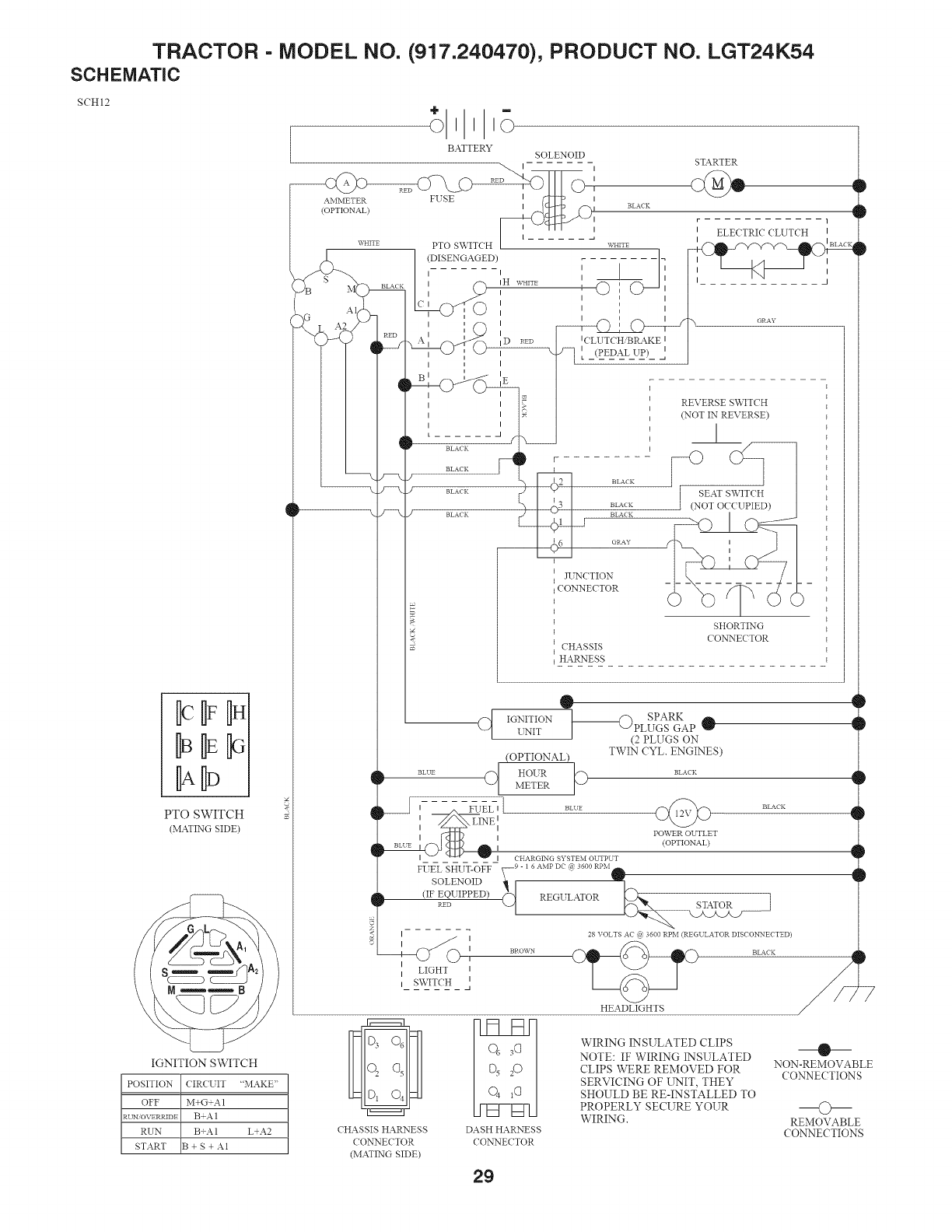
TRACTOR - MODEL NO. (917.240470), PRODUCT NO. LGT24K54
SCHEMATIC
SCHI2
Hc
BID
PTO SWITCH
(MATING SIDE)
IGNITION SWITCH
POSITION ( IR(:UIT "MAKE"
OFF M+G#A1
RUN OVERRIDE B+A1
RUN B+A1 L+A2
START B + S + A1
E
4
q
q
(DISENGAGED)
I I
IH WHITE
CI I
I
I
I D RED
InI
i
InI
_CLUTCH'BRAKE i
--2. q L _(PEDAL UP) ]
BLA(K
BLA(K
BLA(K
OKaY
KTNCTION
CONNECTOR
CHASSIS
HARNESS
STARTER
<g.
BLUE _ METERHOUR
_ ' _JEL' [ .....
//_\ LINE_
I i
BLLE I
I CHARGING SYSTEM OUTPUT
FUEL SHUT-OFF
SOLENOID
tD
tD
ELECTRIC CLUTCH ]
J
REVERSE SWITCH
(NOT IN REVERSE)
!
SHORTING
CONNECTOR
LIGHT
SWITCH
...... d
@
CHASSIS HARNESS
CONNECTOR
(MATING SIDE)
DASH HARNESS
CONNECTOR
®
SPARK
IGNITION ] "_PLUGS GAP O
UNIT (2 PLUGS ON
TWIN CYL. ENGINES)
(OPTIONAL)
BLACK
POWER OUTLET
(OPTIONAL)
28 VOLTS AC 9 3600 RPM (REGULATOR DISCONNECTED)
BLACK
HEADLIGHTS /
q_
q_
P
7
q_
4_
P
WIRING INSULATED CLIPS
NOTE: IF WIRING INSULATED
CLIPS WERE REMOVED FOR
SERVICING OF UNIT, THEY
SHOULD BE RE-INSTALLED TO
PROPERLY SECURE YOUR
WIRING.
®
NON-REMOVABLE
CONNECTIONS
O-
REMOVABLE T
CONNECTION S
29

TRACTOR - MODEL NO. (917.240470), PRODUCT NO. LGT24K54
ELECTRICAL
TO7S
!
I
\\ j-
\/
\/
\\ /
With 12V Outlet Option
103....
59.._
I I
With Service Minder Option
41
i
22
1
16
\
\
/
/
/
42
\
\\
\\
\
I
I
I
I
I
I
iI
I
I
30

TRACTOR - MODEL NO. (917.240470), PRODUCT NO. LGT24K54
ELECTRICAL
KEY PART
NO. NO. DESCRIPTION
1 532 18 34-85 Battery
2 8747804-12 Bolt Hex Hd 1/4-20 unc x 3/4
8 532 18 84-91 Battery Box
18 532 17 81-38 Switch Interlock
21 532 40 02-52 Harness Socket Light
22 532 00 41-52 Bulb, Light # 1158
24 532 40 02-53 Cable Battery
25 532 41 28-95 Cable Starter
28 532 17 51-58 Fuse
27 873 51 04-00 Nut Keps Hex 1/4-20 unc
28 532 14 54-91 Cable Ground 21" BIk 8 Ga.
29 532 40 15-45 Switch Seat
30 532 19 33-50 Switch Ign
33 532 41 19-33 Key/Chain
34 532 11 07-12 Switch Light/Reset
40 532 40 11-04 Harness Ign. Dash
41 817 72 04-08 Screw Thd Cut 1/4-20 x 1/2
42 532 13 15-83 Cover Terminal Red
43 532 19 25-07 Solenoid
48 532 40 17-83 Gauge Hourmeter
50 532 17 48-51 Switch PTO
55 817 08 05-12 Screw Thdrol 5/18-18 x 3/4
59 532 40 03-03 Outlet 12-Volt
71 532 19 42-76 Harness Ign
79 532 17 52-42 Socket Asm Bulb Twistlock
90 532 43 53-95 Cover Terminal Battery
91 532 19 02-70 Strap Battery
92 532 19 66-15 Harness Pigtail Console ROS
93 532 19 25-40 Screw Plastite 10-14 x 2.0
94 532 19 18-34 Module Reverse ROS
99 817 67 04-12 Screw Hexwsh Thdrol 1/4-20 x 3/4
100 8190914-16 Washer 9/32x7/8x16Ga.
103 532 40 79-62 Harness Pigtail 12V Outlet
NOTE: All component dimensions given in U.S. inches
1 inch = 25.4 mm
31
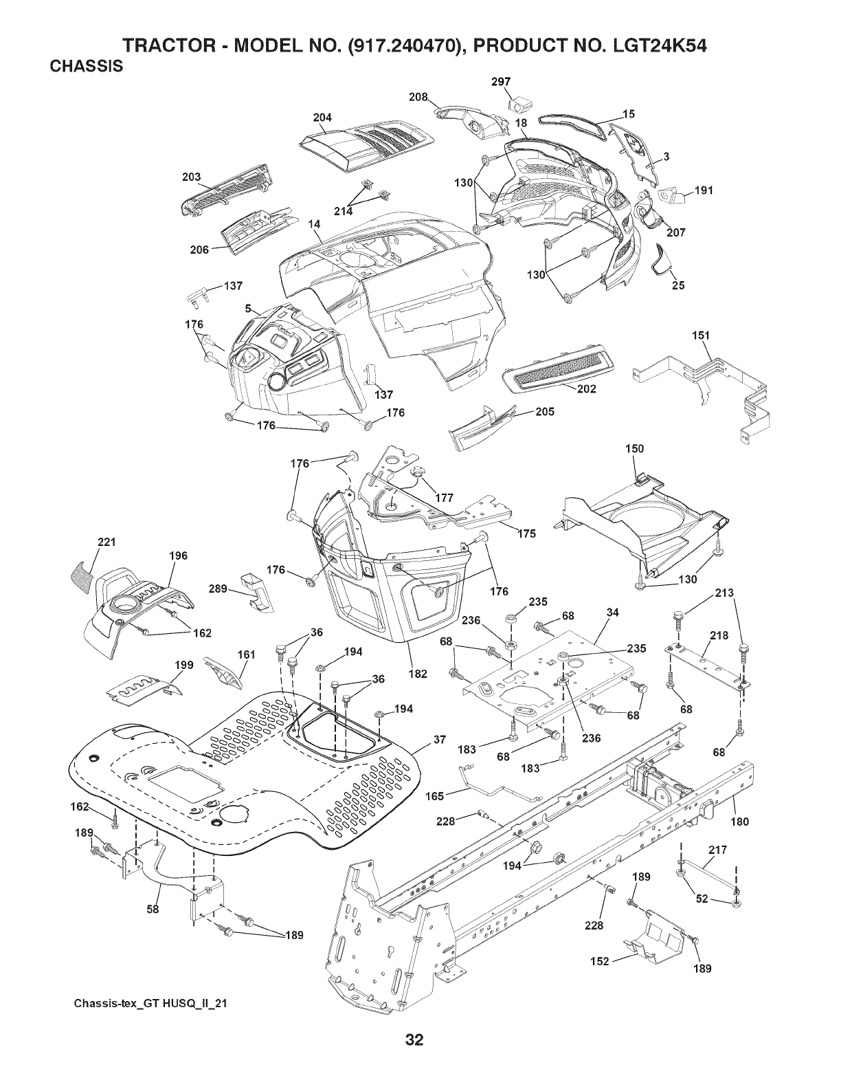
TRACTOR - MODEL NO. (917.240470), PRODUCT NO. LGT24K54
CHASSIS
204
203
\
206
297
18
207
25
176 151
221
196
58
,194
182
37
176 235
228
152
Chassis-te×_GT HUSQ_lI_21
32

TRACTOR - MODEL NO. (917.240470), PRODUCT NO. LGT24K54
CHASSIS
KEY PART KEY PART
NO. NO. DESCRIPTION NO. NO. DESCRiPTiON
3 532 43 97-52 Applique 198 532 40 02-99 Console Asm. Deck Lift
5 532 44 10-51 Dash 199 532 19 82-59 Plate Deck Lift
14 532 44 11-77 Hood 202 532 43 97-28 Vent Side Hood RH
15 532 43 97-33 Lens LH 203 532 43 97-27 Vent Side Hood LH
18 532 40 88-07 Grille 204 532 43 57-14 Vent Asm Hood Top
25 532 43 97-32 Lens RH 205 532 43 97-30 Skirt Hood Side RH
34 532 19 81-25 Plate Engine 208 532 43 97-29 Skirt Hood Side LH
38 817 08 05-12 Screw 5/18-18 x 3/4 207 532 43 97-34 Bezel RH
37 532 44 12-08 Fender 208 532 43 97-35 Bezel LH
52 873 88-05-00 Nut Crown Lock 5/18-18 213 874 78 05-12 Bolt Hex Hd 5/18-18 unc x 3/4
58 532 19 43-14 Bracket Fender 214 532 19 91-45 Clip Retainer
88 817 49 05-08 Screw 5/18-18 x 1/2 217 532 40 91-87 Rod Pivot
130 532 41 83-58 Screw #10 x 0.750 BOS Thread 218 532 19 83-95 Hood Stop X Piece
137 532 40 75-90 Bumper Dash 221 532 19 89-09 Reflector LH
150 532 43 97-74 Duct Heat Hood 228 532 19 51-81 Stud Fastener
151 532 43 88-70 Bracket Pivot 234 532 40 47-42 Bumper Hood
152 532 19 95-35 Shield Browning!Debris 235 532 40 81-29 Spacer Fender
181 532 43 99-29 Console Fuel Window 238 873 93 05-00 Nut Center Lock 5/18-18 unc
182 532 14 24-32 Screw He×Wsh Hi-Lo 1/4 x 1/2 289 532 40 35-71 Plug Cruise/Phone
185 532 19 88-28 Bracket Support Tank 297 532 43 74-58 insert Reflective LH
175 532 19 83-04 Crossmember - - 532 43 18-83 Kit Bumper
178 532 40 07-78 Screw 10-24 × 5/8 Wshd Qdrx
177 532 19 52-27 Bushing Steering
180 532 19 54-77 Chassis
182 532 40 88-59 Dash Lower
183 874 52 05-20 Bolt 5/18-18 × 1-1/4
189 817 00 05-12 Screw 5/18-18 × 3/4
191 532 43 74-55 insert Reflective RH NOTE: All component dimensions given in U.S. inches
194 873 90 05-00 Nut Lock 5/18-18 1 inch = 25.4 mm
33
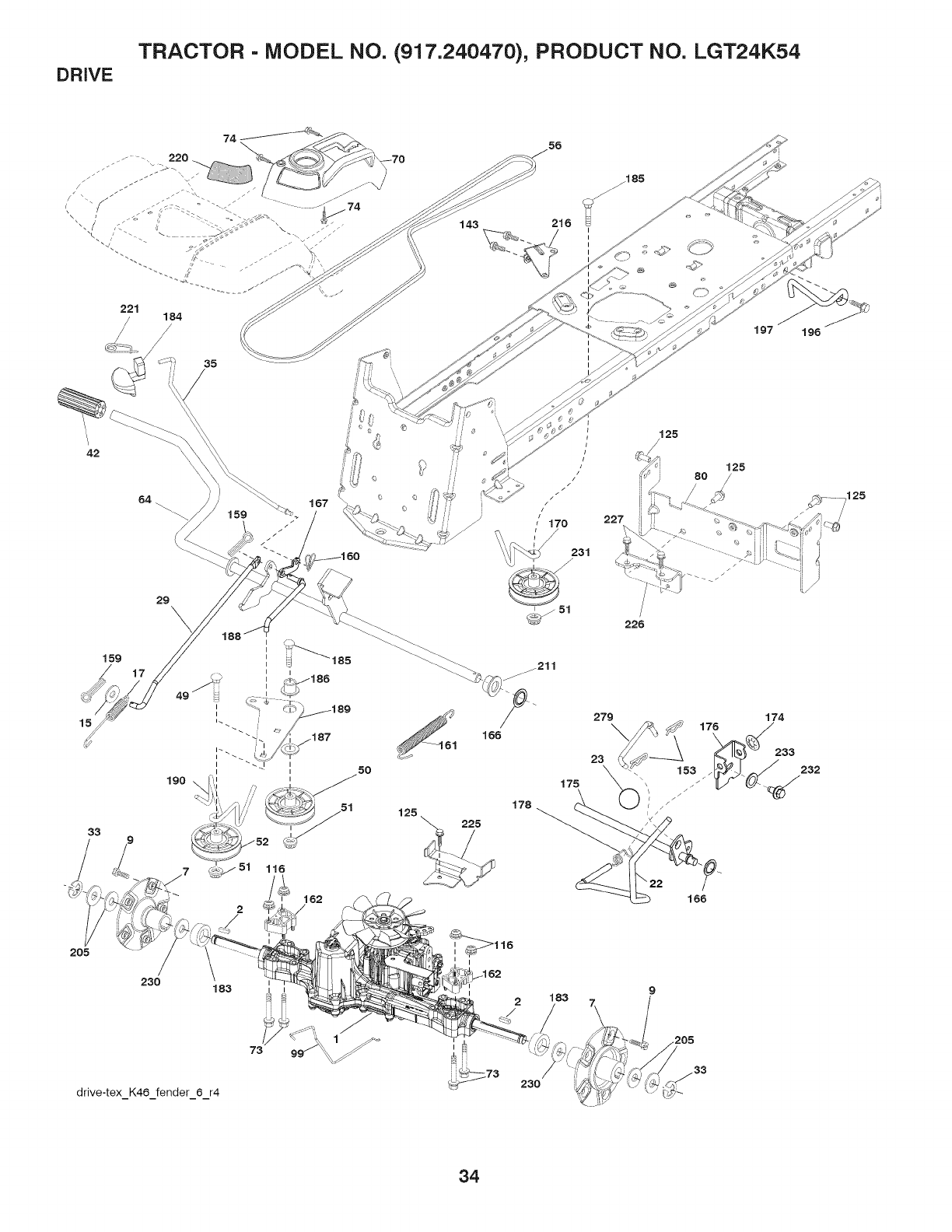
DRIVE TRACTOR - MODEL NO. (917.240470), PRODUCT NO. LGT24K54
221 184
/
35
42
15
33
159
29 \
190
162
2
230 183
drive-tex_K46 fender_6_r4
143 216 I
i
197 196
227
/125
125
80
I
I183
,.205
230
34

DRIVE TRACTOR - MODEL NO. (917.240470), PRODUCT NO. LGT24K54
KEY
NO.
2
7
9
15
17
22
23
29
33
35
42
49
5O
51
52
56
64
70
73
74
8O
99
116
125
143
153
159
160
161
162
166
167
PART
NO.
532 40
532 18
532 19
532 14
819 13
532 41
532 19
532 14
532 40
812 00
532 43
532 12
872 11
532 19
873 90
532 19
532 13
532 19
532 43
874 49
532 14
532 44
532 41
873 90
817 00
817 49
532 12
876 02
532 16
532 10
532 19
532 42
532 40
62-06
62-11
98-44
00-80
13-16
36-78
73-29
08-45
38-06
00-01
54-86
48-72
06-14
43-27
06-00
43-26
09-69
62-00
96-60
05-60
24-32
06-19
57-43
05-00
05-12
05-08
47-88
04-12
94-84
57-09
57-85
91-64
52-57
KEY PART
DESCRIPTION NO. NO. DESCRIPTION
Transaxle, TUFFTORQ K46AW
(See transaxle breakdown)
Key
Hub Asm.Wheel Rear 22"TX GT.06
Bolt Hub Wheel Rear
Washer 13/32 x 13/16 x 16 Ga.
Spring Brake
Rod Shift
Knob
Rod, Brake
Ring E
Rod Brake Park
Cover Foot Pedal
Bolt
Pulley Idler Flat
Lock Nut 3/8-16
Idler V-Groove 910" Offset
V-Belt Drive
Shaft Asm. Pedal Brake Control
Console Asm.
Bolt Hex Flghd 5/16-18 x 3.75
Screw 1/4 x 1/2
Strap Torque
Rod Bypass
Nut Lock Hex Flange 5/16-18
Screw 5/16-18 x 3/4
Screw 5/16-18 x 1/2
Retainer Spring
Pin Cotter 1/8 x 3/4
Retainer Clip
Spring Return Clutch
Spacer Transaxle 18 and 22
Nut Push
Latch Brake Parking
170 532 41 34-30
174 532 19 72-89
175 532 40 62-08
176 532 19 62-14
178 532 19 74-56
183 532 40 04-24
184 532 44 14-55
185 872 11 06-22
186 532 19 43-21
187 819 13 32-10
188 532 19 43-23
189 5321943-17
190 532 19 43-18
196 817 00 06-16
197 532 19 97-69
205 532 12 17-48
211 532 19 62-12
216 532 19 61-31
220 532 19 89-08
221 532 40 31-87
225 532 40 33-19
226 532 40 08-31
227 817 49 05-12
230 532 18 89-67
231 532 40 72-87
232 874 78 07-16
233 532 40 52-96
279 532 40 62-07
Keeper Belt Centerspan
Nut Push
Shaft Asm Shift
Arm Clevis Rod Shift
Spring Shift
Spacer Split
Handle Parking Brake
Bolt Rdhd Sqnk 3/8-16 x 2-3/4 Gr. 5
Spacer Retainer
Washer
Link Clutch Ground Drive
Bellcrank Ground Drive
Keeper Bellcrank Ground Drive
Screw 3/8-16 x 1
Link Clutch Anti-Rotation
Washer
Bushing Brake Shaft
Bracket Pulley Idler
Reflector RH
Retainer Spring Clip Handle
Keeper Belt Trans.
Bracket Mount Torque
Screw Thdrol. 5/16-18 x 3/4
Washer Hardened
Idler V-Groove 1.688" Offset
Bolt 7/16-14 x 1 Gr. 5
Washer Serrated
Link Shift
NOTE: All component dimensions given in U.S. inches
1 inch = 25.4 mm
35
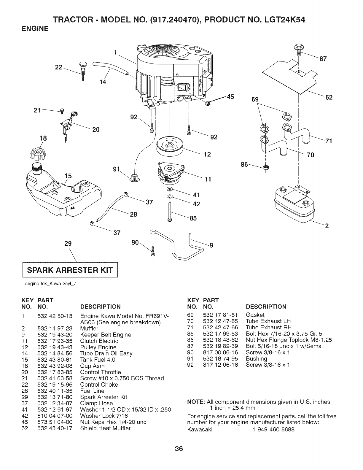
TRACTOR - MODEL NO. (917.240470), PRODUCT NO. LGT24K54
ENGINE
14
2o
1
15
29
\i
SPARK ARRESTER KiT /
engine-tex Kawa-2cyl 7
92
12
11
41
42
7O
KEY PART
NO. NO. DESCRIPTION
1 532 42 50-13
2 532 14 97-23
9 532 19 43-20
11 532 17 93-35
12 532 19 43-43
14 532 14 84-56
15 532 43 80-81
18 532 43 92-08
20 532 17 83-85
21 532 41 63-58
22 532 19 15-96
28 532 40 11-35
29 532 13 71-80
37 532 12 34-87
41 532 12 61-97
42 810 04 07-00
45 873 51 04-00
62 532 43 40-17
Engine Kawa Model No. FR691V-
AS06 (See engine breakdown)
Muffler
Keeper Belt Engine
Clutch Electric
Pulley Engine
Tube Drain Oil Easy
Tank Fuel 4.0
Cap Asm
Control Throttle
Screw #10 x 0.750 BOS Thread
Control Choke
Fuel Line
Spark Arrester Kit
Clamp Hose
Washer 1-1/20D x 15/32 ID x .250
Washer Lock 7/16
Nut Keps Hex 1/4-20 unc
Shield Heat Muffler
KEY PART
NO. NO. DESCRIPTION
69 532 17 81-51 Gasket
70 532 42 47-65 Tube Exhaust LH
71 532 42 47-66 Tube Exhaust RH
85 532 17 99-53 Bolt Hex 7/16-20 x 3.75 Gr. 5
86 532 18 43-62 Nut Hex Flange Toplock M8-1.25
87 532 19 82-39 Bolt 5/16-18 unc x 1 w/Sems
90 817 00 06-16 Screw 3/8-16 x 1
91 532 18 74-95 Bushing
92 817 12 06-16 Screw 3/8-16 x 1
NOTE: All component dimensions given in U.S. inches
1 inch = 25.4 mm
For engine service and replacement parts, call the toll free
number for your engine manufacturer listed below:
Kawasaki 1-949-460-5688
36
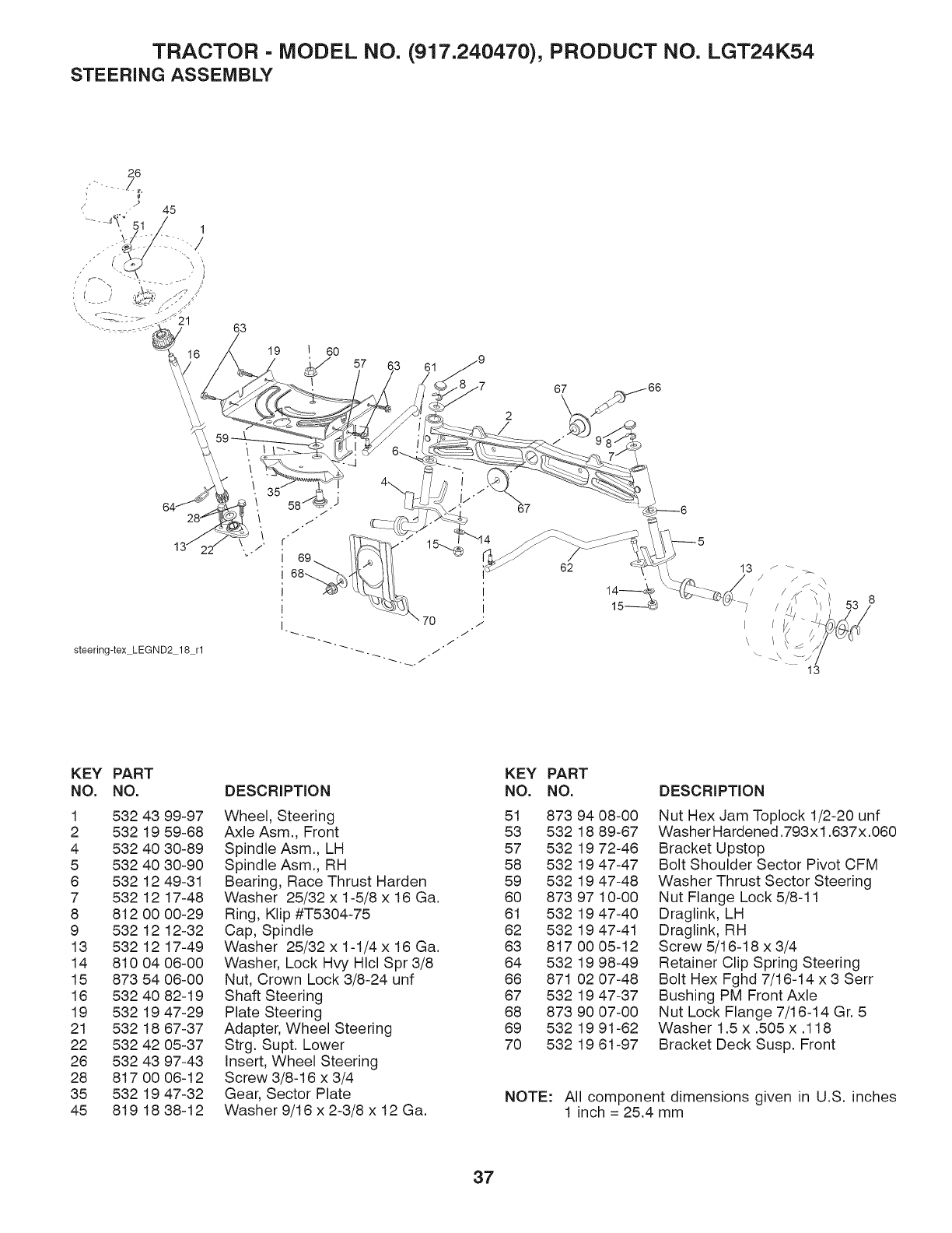
TRACTOR - MODEL NO. (917.240470), PRODUCT NO. LGT24K54
STEERING ASSEMBLY
steering-tex LEGND2 18 rl
63
19 I 60
61
67
67 / 66
62
KEY PART
NO. NO.
1 532 43 99-97
2 532 19 59-68
4 532 40 30-89
5 532 40 30-90
6 532 12 49-31
7 532 12 17-48
8 812 00 00-29
9 532 12 12-32
13 532 12 17-49
14 810 04 06-00
15 873 54 06-00
16 532 40 82-19
19 532 19 47-29
21 532 18 67-37
22 532 42 05-37
26 532 43 97-43
28 817 00 06-12
35 532 19 47-32
45 819 18 38-12
DESCRiPTiON
Wheel, Steering
Axle Asm., Front
Spindle Asm., LH
Spindle Asm., RH
Bearing, Race Thrust Harden
Washer 25/32 x 1-5/8 x 16 Ga.
Ring, Klip #T5304-75
Cap, Spindle
Washer 25/32 x 1-1/4 x 16 Ga.
Washer, Lock Hvy Hlcl Spr 3/8
Nut, Crown Lock 3/8-24 unf
Shaft Steering
Plate Steering
Adapter, Wheel Steering
Strg. Supt. Lower
Insert, Wheel Steering
Screw 3/8-16 x 3/4
Gear, Sector Plate
Washer 9/16 x 2-3/8 x 12 Ga.
KEY PART
NO. NO.
51 873 94 08-00
53 532 18 89-67
57 532 19 72-46
58 532 19 47-47
59 532 19 47-48
60 873 97 10-00
61 532 19 47-40
62 532 19 47-41
63 817 00 05-12
64 532 19 98-49
66 871 02 07-48
67 532 19 47-37
68 873 90 07-00
69 532 19 91-62
70 532 19 61-97
DESCRiPTiON
Nut Hex Jam Toplock 1/2-20 unf
Washer Hardened .793x 1.637 x.060
Bracket Upstop
Bolt Shoulder Sector Pivot CFM
Washer Thrust Sector Steering
Nut Flange Lock 5/8-11
Draglink, LH
Draglink, RH
Screw 5/16-18 x 3/4
Retainer Clip Spring Steering
Bolt Hex Fghd 7/16-14 x 3 Serr
Bushing PM Front Axle
Nut Lock Flange 7/16-14 Gr. 5
Washer 1.5 x .505 x .118
Bracket Deck Susp. Front
NOTE: All component dimensions given in U.S. inches
1 inch = 25.4 mm
37
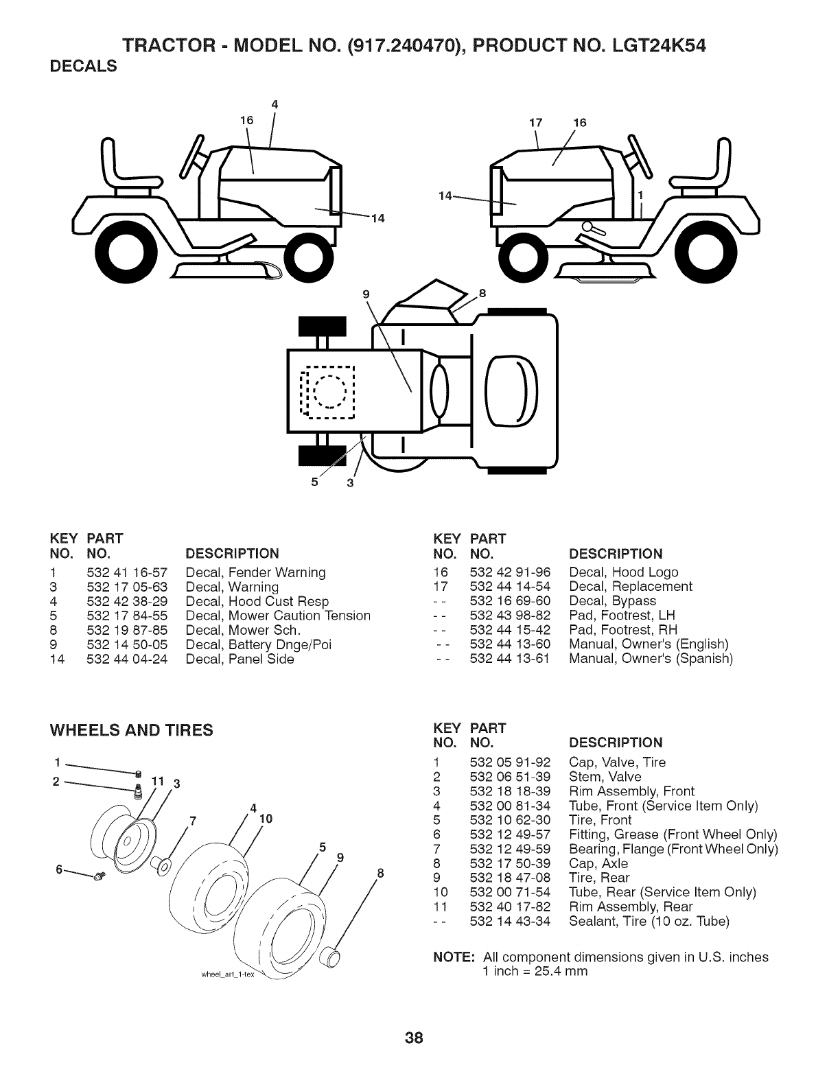
TRACTOR - MODEL NO. (917.240470), PRODUCT NO. LGT24K54
DECALS
4
16 17 16
9 8
53
KEY PART
NO. NO.
1 532 41 18-57 Decal
3 532 17 05-83 Decal
4 532 42 38-29 Decal
5 532 17 84-55 Decal
8 532 19 87-85 Decal
9 532 14 50-05 Decal
14 532 44 04-24 Decal
DESCRIPTION
Fender Warning
Warning
Hood Cust Resp
Mower Caution Tension
Mower Sch.
Battery Dnge/Poi
Panel Side
KEY PART
NO. NO.
18 532 42 91-98
17 532 44 14-54
-- 532 16 89-80
- - 532 43 98-82
- - 532 44 15-42
- - 532 44 13-80
- - 532 44 13-81
DESCRiPTiON
Decal, Hood Logo
Decal, Replacement
Decal, Bypass
Pad, Footrest, LH
Pad, Footrest, RH
Manual, Owner's (English)
Manual, Owner's (Spanish)
WHEELS AND TIRES
1
23
7410
wheel art
59
KEY PART
NO. NO.
1 532 05 91-92
2 532 08 51-39
3 532 18 18-39
4 532 00 81-34
5 532 10 62-30
8 532 12 49-57
7 532 12 49-59
8 532 17 50-39
9 532 18 47-08
10 532 00 71-54
11 532 40 17-82
- - 532 14 43-34
DESCRiPTiON
Cap, Valve, Tire
Stem, Valve
Rim Assembly, Front
Tube, Front (Service Item Only)
Tire, Front
Fitting, Grease (Front Wheel Only)
Bearing, Flange (Front Wheel Only)
Cap, Axle
Tire, Rear
Tube, Rear (Service Item Only)
Rim Assembly, Rear
Sealant, Tire (10 oz. Tube)
NOTE: All component dimensions given in U.S. inches
1 inch = 25.4 mm
38
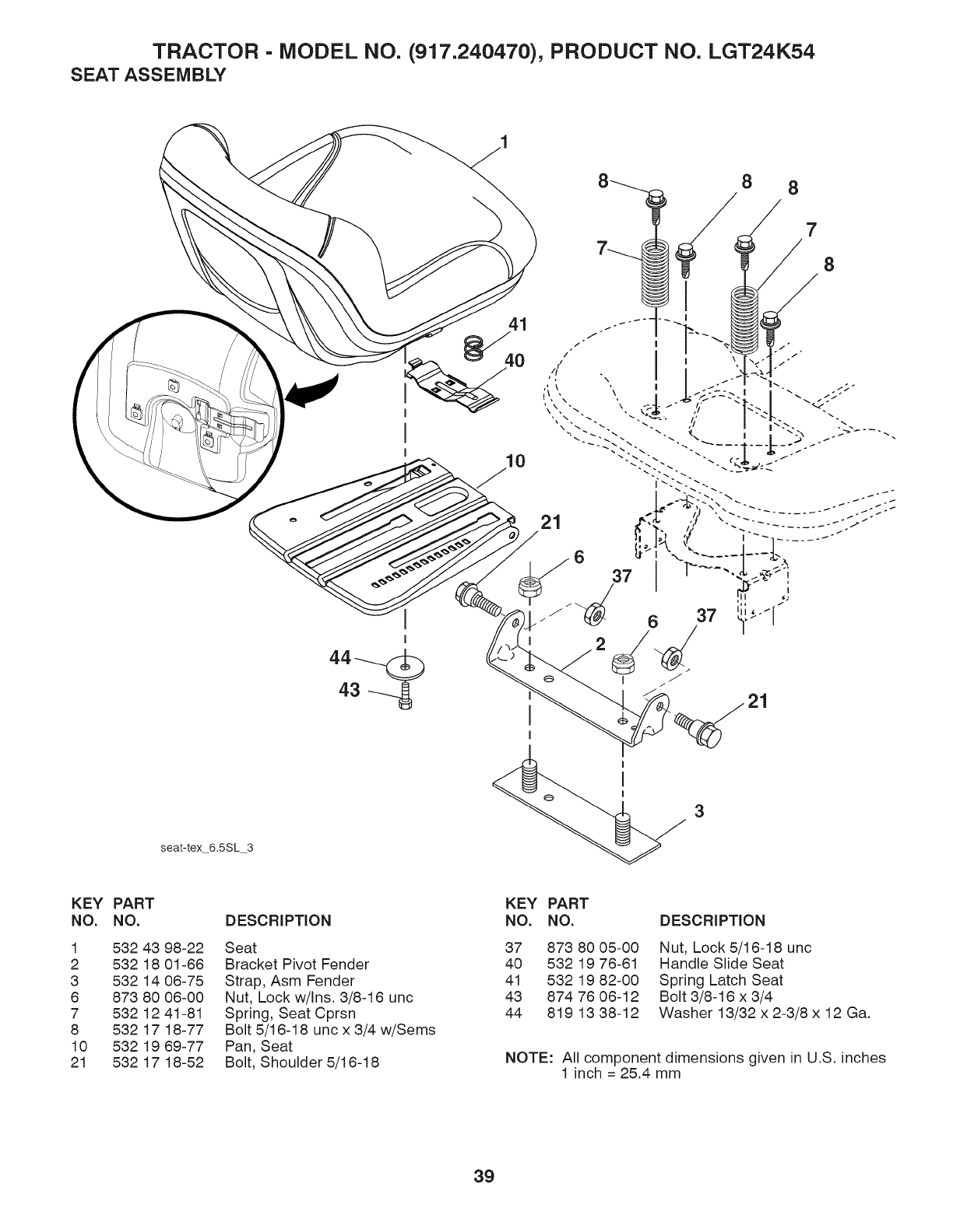
TRACTOR - MODEL NO. (917.240470), PRODUCT NO. LGT24K54
SEAT ASSEMBLY
8 8
41
7
8
21
seat-tex_6.5SL_3
3
KEY PART
NO. NO. DESCRIPTION
1 532 43 98-22 Seat
2 532 18 01-66 Bracket Pivot Fender
3 532 14 06-75 Strap, Asm Fender
6 873 80 06-00 Nut, Lock w/Ins. 3/8-16 unc
7 532 12 41-81 Spring, Seat Cprsn
8 532 17 18-77 Bolt 5/16-18 unc x 3/4 w/Sems
10 532 19 69-77 Pan, Seat
21 532 17 18-52 Bolt, Shoulder 5/16-18
KEY PART
NO. NO.
37 873 80 05-00
40 532 19 76-61
41 532 19 82-00
43 874 76 06-12
44 819 13 38-12
DESCRIPTION
Nut, Lock 5/16-18 unc
Handle Slide Seat
Spring Latch Seat
Bolt 3/8-16 x 3/4
Washer 13/32 x 2-3/8 x 12 Ga.
NOTE: All component dimensions given in U.S. inches
1 inch = 25.4 mm
39
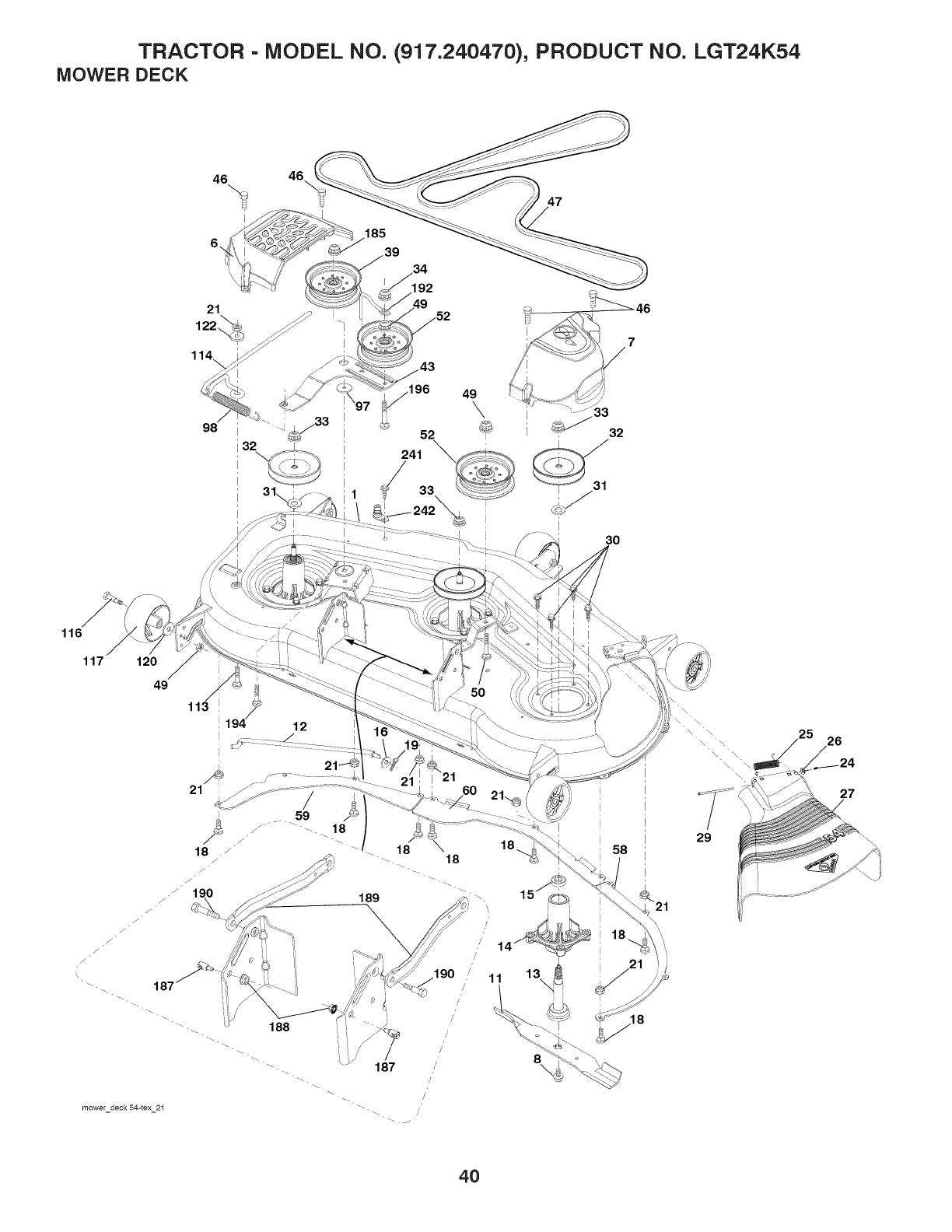
TRACTOR - MODEL NO. (917.240470), PRODUCT NO. LGT24K54
MOWER DECK
46 46\
6, 185
39
47
21
122_
114
98
32
1
I
43
116
117 120
49
21
/
18 /
12
mower deck 54-tex 21
18
/
/
/
,' 11
/'
/
/
/
/, 8
\ \
\
29
26
27
40
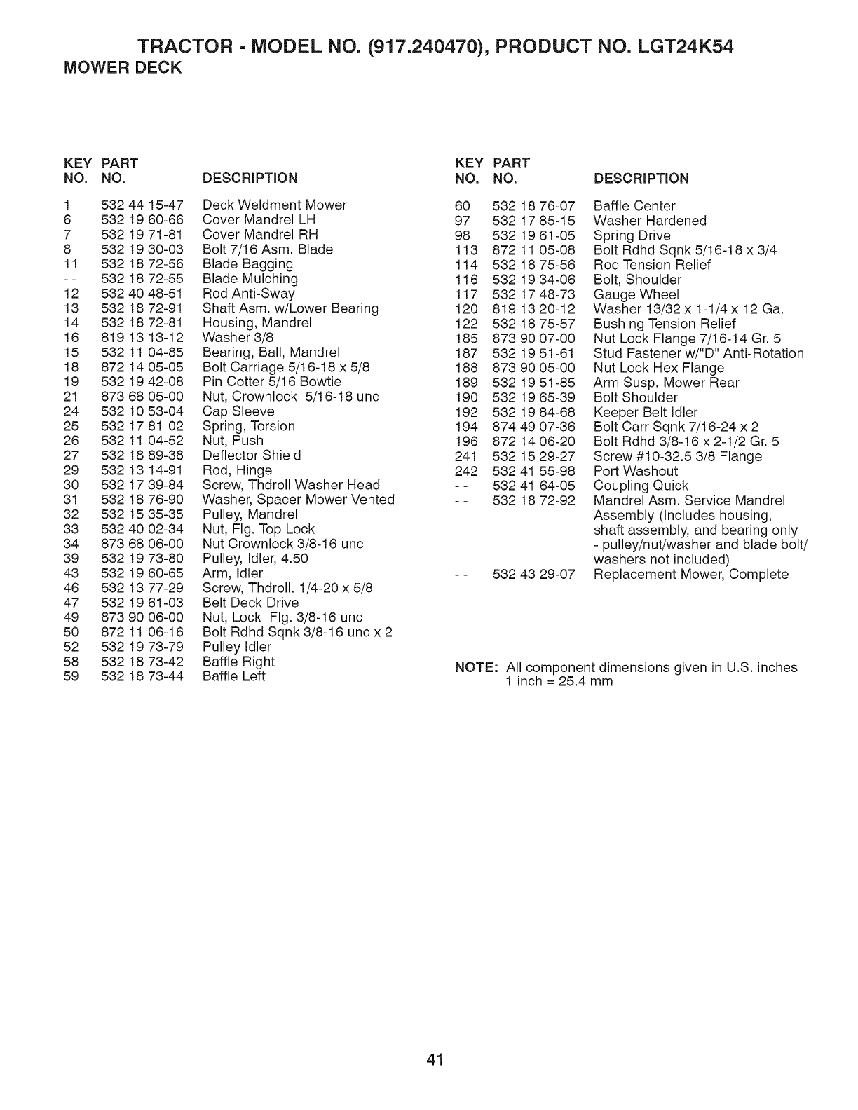
TRACTOR - MODEL NO. (917.240470), PRODUCT NO. LGT24K54
MOWER DECK
KEY PART KEY PART
NO. NO. DESCRIPTION NO. NO. DESCRIPTION
1 532 44 15-47 Deck Weldment Mower
6 532 19 60-66 Cover Mandrel LH
7 532 19 71-81 Cover Mandrel RH
8 532 19 30-03 Bolt 7/16 Asm. Blade
11 532 18 72-56 Blade Bagging
--532 18 72-55 Blade Mulching
12 532 40 48-51 Rod Anti-Sway
13 532 18 72-91 Shaft Asm. w/Lower Bearing
14 532 18 72-81 Housing, Mandrel
16 819 13 13-12 Washer3/8
15 532 11 04-85 Bearing, Ball, Mandrel
18 872 14 05-05 Bolt Carriage 5/16-18 x 5/8
19 532 19 42-08 Pin Cotter 5/16 Bowtie
21 873 68 05-00 Nut, Crownlock 5/16-18 unc
24 532 10 53-04 Cap Sleeve
25 532 17 81-02 Spring, Torsion
26 532 11 04-52 Nut, Push
27 532 18 89-38 Deflector Shield
29 532 13 14-91 Rod, Hinge
30 532 17 39-84 Screw, Thdroll Washer Head
31 532 18 76-90 Washer, Spacer Mower Vented
32 532 15 35-35 Pulley, Mandrel
33 532 40 02-34 Nut, Fig. Top Lock
34 873 68 06-00 Nut Crownlock 3/8-16 unc
39 532 19 73-80 Pulley, Idler, 4.50
43 532 19 60-65 Arm, Idler
46 532 13 77-29 Screw, Thdroll. 1/4-20 x 5/8
47 532 19 61-03 Belt Deck Drive
49 873 90 06-00 Nut, Lock Fig. 3/8-16 unc
50 872 11 06-16 Bolt Rdhd Sqnk 3/8-16 unc x 2
52 532 19 73-79 Pulley Idler
58 532 18 73-42 Baffle Right
59 532 18 73-44 Baffle Left
60 532 18 76-07
97 532 17 85-15
98 532 19 61-05
113 8721105-08
114 5321875-56
116 5321934-06
117 5321748-73
120 819 13 20-12
122 532 18 75-57
185 873 90 07-00
187 532 19 51-61
188 873 90 05-00
189 532 19 51-85
190 532 19 65-39
192 532 19 84-68
194 874 49 07-36
196 872 14 06-20
241 532 15 29-27
242 532 41 55-98
- - 532 41 64-05
-- 532 18 72-92
532 43 29-07
Baffle Center
Washer Hardened
Spring Drive
Bolt Rdhd Sqnk 5/16-18 x 3/4
Rod Tension Relief
Bolt, Shoulder
Gauge Wheel
Washer 13/32 x 1-1/4 x 12 Ga.
Bushing Tension Relief
Nut Lock Flange 7/16-14 Gr. 5
Stud Fastener w/"D" Anti-Rotation
Nut Lock Hex Flange
Arm Susp. Mower Rear
Bolt Shoulder
Keeper Belt Idler
Bolt Carr Sqnk 7/16-24 x 2
Bolt Rdhd 3/8-16 x 2-1/2 Gr. 5
Screw #10-32.5 3/8 Flange
Port Washout
Coupling Quick
Mandrel Asm. Service Mandrel
Assembly (Includes housing,
shaft assembly, and bearing only
- pulley/nut/washer and blade bolt/
washers not included)
Replacement Mower, Complete
NOTE: All component dimensions given in U.S. inches
1 inch = 25.4 mm
41
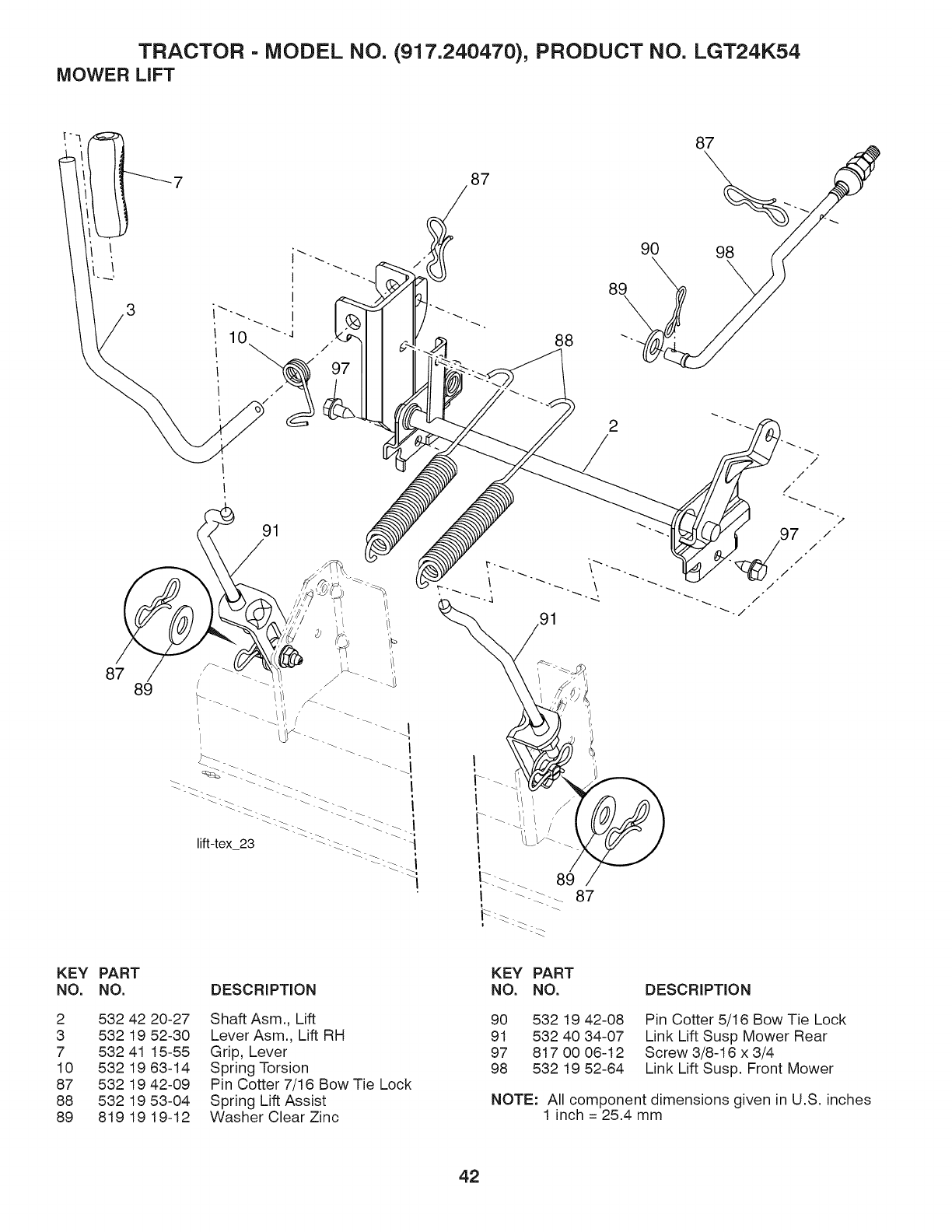
TRACTOR - MODEL NO. (917.240470), PRODUCT NO. LGT24K54
MOWER LIFT
91
87 89
87
88
2
//
/
97
91
KEY PART
NO, NO, DESCRIPTION
2 532 42 20-27 ShaftAsm., Lift
3 532 19 52-30 Lever Asm., Lift RH
7 532 41 15-55 Grip, Lever
10 532 19 63-14 Spring Torsion
87 532 19 42-09 Pin Cotter 7/16 Bow Tie Lock
88 532 19 53-04 Spring Lift Assist
89 819 19 19-12 Washer Clear Zinc
KEY PART
NO. NO. DESCRIPTION
90 532 19 42-08
91 532 40 34-07
97 817 00 06-12
98 532 19 52-64
Pin Cotter 5/16 Bow Tie Lock
Link Lift Susp Mower Rear
Screw 3/8-16 x 3/4
Link Lift Susp. Front Mower
NOTE: All component dimensions given in U.S. inches
1 inch = 25.4 mm
42
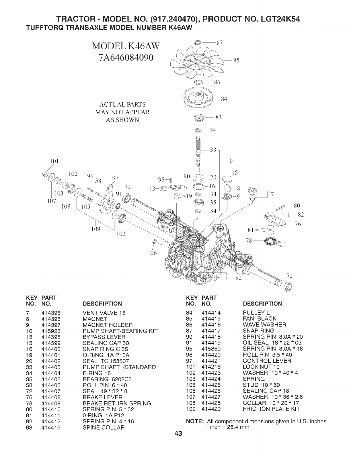
TRACTOR - MODEL NO. (917.240470), PRODUCT NO. LGT24K54
TUFFTORQ TRANSAXLE MODEL NUMBER K46AW
MODEL K46AW
7A646084090
ACTUAL PARTS
MAY NOT APPEAR
AS SHOWN
87
86
__ 84
@83
lOl
@ 34
106
10
85
15
KEY
NO.
7
8
9
10
13
15
16
19
20
33
34
35
58
72
76
78
80
81
82
83
PART
NO.
414395
414398
414397
415923
414398
414399
414400
414401
414402
414403
414404
414405
414408
414407
414408
414409
414410
414411
414412
414413
DESCRIPTION
VENT VALVE 15
MAGNET
MAGNET HOLDER
PUMP SHAFT/BEARING KIT
BYPASS LEVER
SEALING CAP 30
SNAP RING C 35
O-RING IAP10A
SEAL TC 153507
PUMP SHAFT (STANDARD
E-RING 15
BEARING 8202C3
ROLL PIN 8" 40
SEAL 19"32"8
BRAKE LEVER
BRAKE RETURN SPRING
SPRING PIN 5"32
0-RING 1AP12
SPRING PIN 4" 18
SPINE COLLAR 43
KEY PART
NO. NO. DESCRIPTION
84 414414 PULLEY L
85 414415 FAN, BLACK
88 414418 WAVE WASHER
87 414417 SNAP RING
90 414418 SPRING PIN 3.0A'20
91 414419 OIL SEAL 18"22"03
95 415850 SPRING PIN 3.0A * 18
98 414420 ROLL PIN 3.5 * 40
97 414421 CONTROL LEVER
101 414218 LOCK NUT 10
102 414423 WASHER 10"40"4
103 414424 SPRING
105 414425 STUD 10"60
108 414428 SEALING CAP 18
107 414427 WASHER 10"36"2.8
108 414428 COLLAR 10"20"17
109 414429 FRICTION PLATE KIT
NOTE: All component dimensions given in U.S. inches
1 inch = 25.4 mm
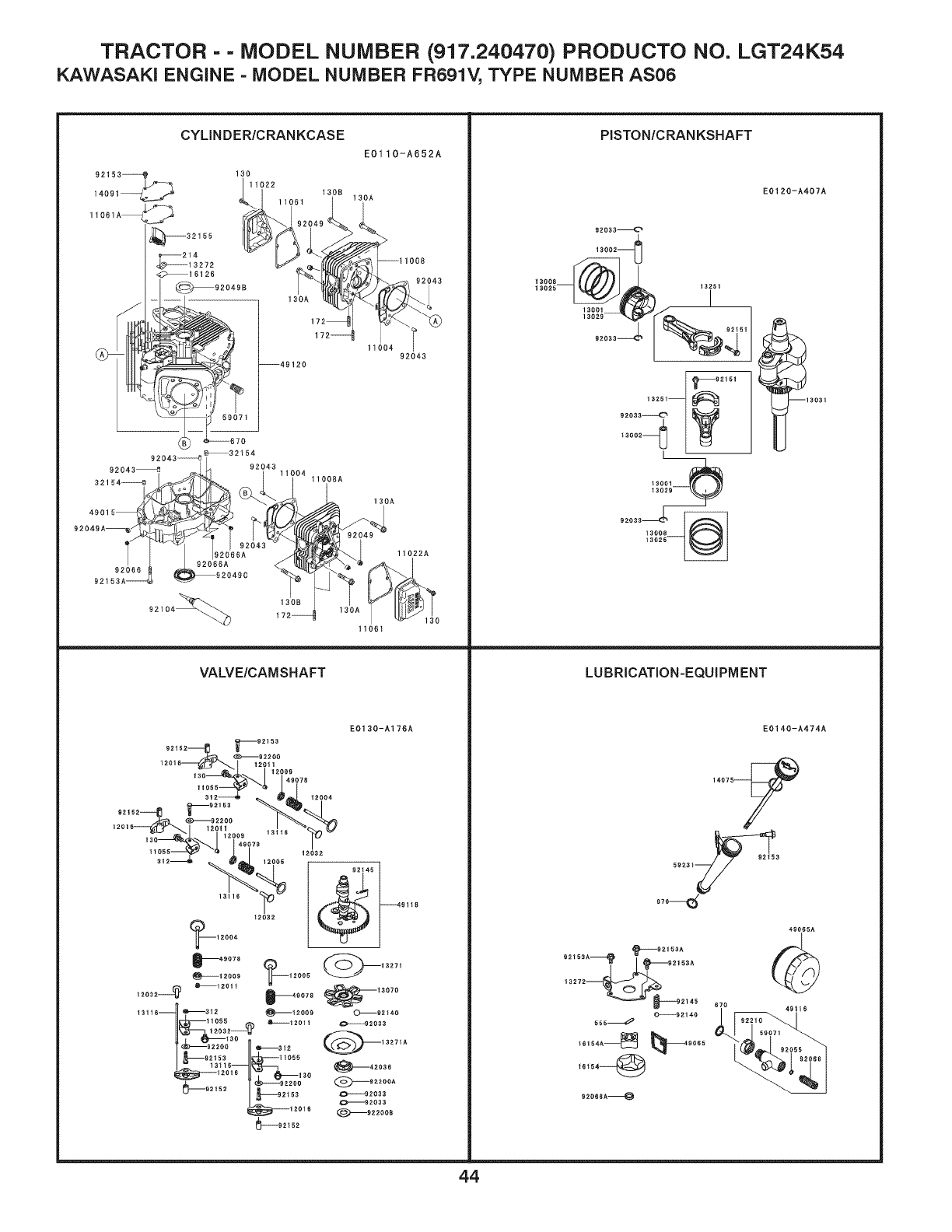
TRACTOR =- MODEL NUMBER 1917.240470) PRODUCTO NO. LGT24K54
KAWASAK! ENGINE - MODEL NUMBER FR691V, TYPE NUMBER AS06
CYLINDER/CRANKCASE
92153_
11061A
32155
_214
_ .................13272
_16126
62o499
1
-_
130
11922
130B
11061
130A
--49120
E0110-A652A
130A
11008
1192i4_
92043
PISTON/CRANKSHAFT
92033_
13002]_{_}
'_92151
130A
92043 ..................o _32154
92043_ 92043
3216_
49015_
92049A_
92_ _920499
92153A------_
)O4
11022A
Im
92104_)
130B
11061
VALVE/CAMSHAFT
EO130-A176A
12016 12011
130 120%078
12009 13116 %_
130 49078
I12032
i_112___ _9116
13116_3t2 _t2000 _O_62140
11053 _12011
_92200 _3_2
_2153 11055
_62152 _-----62200 @62_00A
|_--021,3o---.06,
_12016 J1_92033
_9_200B
_92t52
LUBRICATION=EQUIPMENT
E0120-A407A
16031
E0140-A474A
14075-_
/
670 5923t_ __92153
49065A
_62166A
o2162, , _o2163A
O_21_0
655_
16t54_
62o66A_
670
44
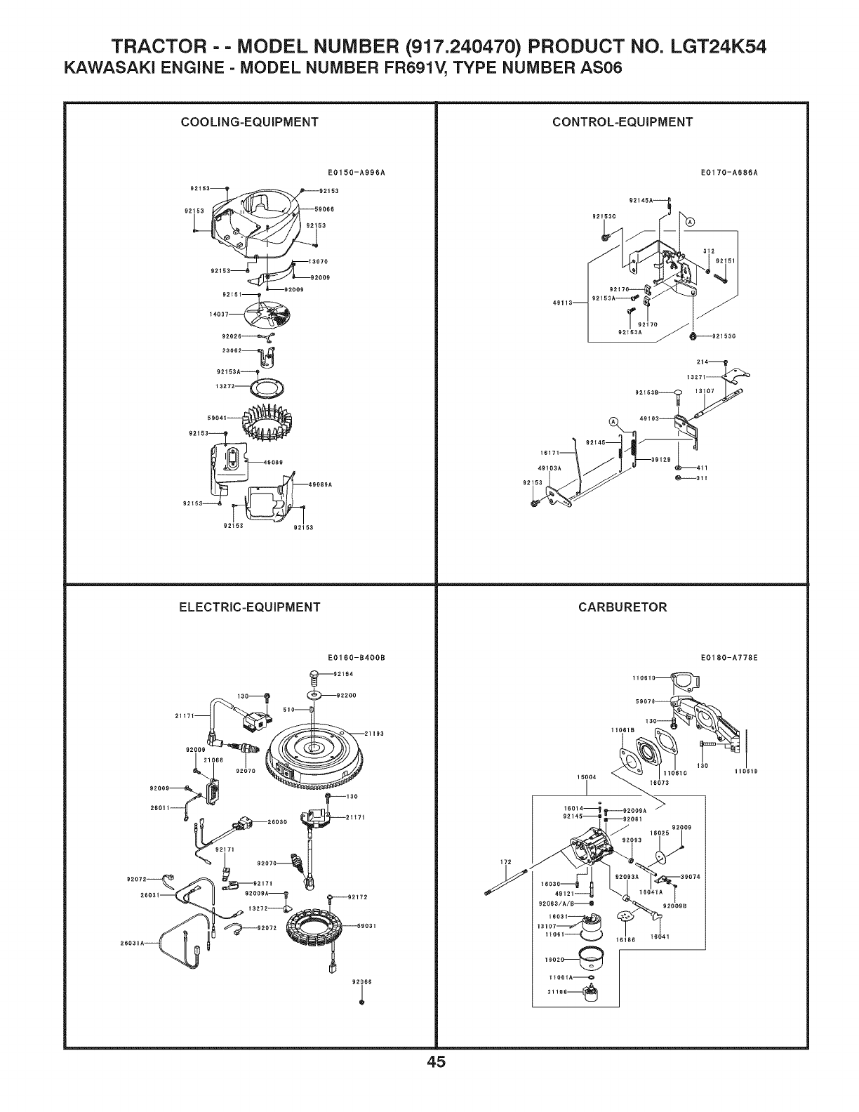
TRACTOR -- MODEL NUMBER (917.240470) PRODUCT NO. LGT24K54
KAWASAK! ENGINE - MODEL NUMBER FR691V, TYPE NUMBER AS06
COOLING-EQUIPMENT
92153
92t5]_
E01 50-A996A
_i 2153
59066
3
3070
92009
--92009
t4.037_
92026_
23062_
59041
921_3_
9089
92_5_ 92_53
ELECTRIC-EQUIPMENT
CONTROL-EQUIPMENT
E0170-A686A
CARBURETOR
E0160-B400B
110610_
92154
92i66
E0180-A778E
I
t1061D
45
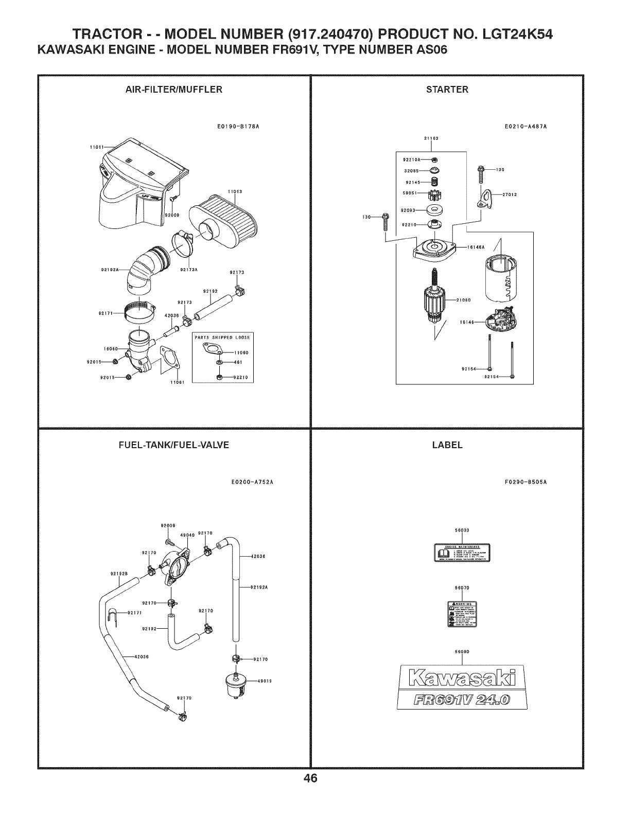
TRACTOR = - MODEL NUMBER (917.240470) PRODUCT NO. LGT24K54
KAWASAK! ENGINE = MODEL NUMBER FR691V, TYPE NUMBER AS06
AIR=FILTER/MUFFLER
EO190-B178A
11011
t1013
92192A REt73A 9R192 RRt73
9217]_ 92173
PARTS SHIPPED LOOSE
tORO
61
92015-_ /_92210
tlO6t
FUEL=TANK/FUEL=VALVE
EO200-A752A
_92t70
STARTER
21163
!
922tOA_
32085@
R2145_
5R051_
16146_
LABEL
56033
L :i
56O70
56080
I
EO210-A487A
F0290-B505A
46

TRACTOR -- MODEL NUMBER (917.240470) PRODUCT NO. LGT24K54
KAWASAKI ENGINE = MODEL NUMBER FR691V, TYPE NUMBER AS06
CYLINDER/CRANKCASE
11004 11004-7026 Gasket-Head
11008 11008-7039 Head-Comp-Cylinder,#1
11008a 11008-7040 Head-Comp-Cylinder,#2
11022 11022-7019 Case- Rocker,#1
11022a 11022-7020 Case-Rocker,#2
11061 11061-7083 Gasket,Case-Rocker
11061a 11061-7094 Gasket,Breather
13272 13272-7004 Plate,Breather
14091 14091-7064 Cover, Breather
16126 16126-7020 Valve,Breather
32154 32154-7019 Pipe
32155 32155-7003 Pipe,Breather
49015 49015-7106 Cover-Crankcase
49120 49120-7142 Crankcase-Com p
59071 59071-2079 Joint
92043 92043-1263 Pin
92049 92049-7001 SeaI-OiI,Rvc2 6xl lx10.2
92049a 92049-7005 Seal-Oil,So 8x14x5 Hs
92049b 92049-7010 SeaI-Oil,Sd 35x48x8 R
92049c 92049-7028 SeaI-Oil,38x62x8mtclv
92066 92066-7023 Plug
92066a 92066-7026 Plug
92104 92104-7001 Gasket- Liquid,Tb 1217h
92153 92153-7043 Bolt,6xl 2
92153a 92153-7054 Bolt,8x50
130 130aa0625 Bolt-Flanged,6x25
130a 130ca1050 Bolt-Flanged,10x50
130b 130ca1065 Bolt-Flanged,10x65
172 172ba0818 Bolt-Stud,8xl 8
214 214aa0408 Screw-Pan+-,4x8
670 670b2011 O Ring,11mm
PISTON/CRAN KSHAFT
13001 13001-7027 Piston-Engine
13002 13002-7006 Pin-Piston
13008 13008-7005 Ring-Set-Piston
13025 13025-7009 Ring-Set-Piston L,0.5
13029 13029-7010 Piston-Engine L,0.5
13031 13031-7083 Crankshaft-Comp
13251 13251-7025 Rod-Assy-Connecting
92033 92033-7018 Ring-Snap
92151 92151-7017 Bolt,6x35
AIR=FILTER/MUFFLER
11011 11011-7065 Case-Air Filter
11013 11013-7049 Element-Air Filter
11060 11060-7016 Gasket,Muffler
11061 11061-7086 Gasket,Carburetor/Pipe-
Intake
16060 16060-7035 Pipe-I ntake
42036 42036-7017 Sleeve,Breather
92009 92009-2303 Screw
92015 92015-1367 Nut
92171 92171-7007 Clamp
92173 92173-7003 Clamp
92173a 92173-7007 Clamp
92192 92192-7146 Tube,12.6x18.6x118
92192a 92192-7165 Tube
92210 92210-7027 Nut,M 8
461 461da0800 Washer-Spring,8mm
Ms
LUBRICATION=EQUIPM ENT
13272 13272-7011
14075 14075-7013
16154 16154-7010
16154a 16154-7011
49065 49065-7006
49065a 49065-7007
49116 49116-7001
59071 59071-7008
59231 59231-7016
92055 92055-7002
92066 92066-7007
92066a 92066-7028
92140 92140-7003
92145 92145-7002
92153 92153-7008
92153a 92153-7043
92210 92210-7012
555 555a0420
670 670d2016
Plate, Rotor
Cap-Assy, Oil Gauge
Rotor-Pump,Outer
Rotor-Pump,Inner
Filter-Oil
Filter-Oil
Valve-Assy
Joint
Filler
Ring-O,6mm
Plug
Plug
Ball
Spring
Bolt
Bolt,6x12
Nut,M22
Pin-Spring,4x20
O Ring,16mm
ELECTRIC=EQUIPMENT
13272 13272-7012 Plate
21066 21066-7017 Regulator-Voltage
21171 21171-7047 CoiI-Assy-lgnition
21193 21193-7038 FlywheeI-Assy
26011 26011-7025 Wire-Lead,L=95
26030 26030-7008 Harness
26031 26031-7040 Harness
26031a 26031-7041 Harness
59031 59031-7017 Coil-Charging
92009 92009-2303 Screw
92009a 92009-2308 Screw
92066 92066-7026 Plug
92070 92070-7004 Plug-Spark, Bpr4es(Ngk),
Solid
92072 92072-7003 Band
92154 92154-7003 Bolt,12x30
92171 92171-7008 Clamp
92172 92172-7018 Screw,5x20
92200 92200-7002 Washer
130 130aa0620 Bolt-Flanged,6x20
510 510a5100 Key-Woodruff
COOLING=EQUIPMENT
13070 13070-7019 Guide,Cooling Air
13272 13272-7006 Plate,Fan
14037 14037-7008-9h Screen
23062 23062-7022 Bracket-Comp
49089 49089-7079 Shroud-Engine
49089a 49089-7080 Shroud-Engine
59041 59041-7014 Fan
59066 59066-7052 Housing-Fan
92009 92009-2303 Screw
92026 92026-7007 Spacer
92151 92151-7012 Bolt,6x12
92153 92153-7007 Bolt
92153a 92153-7043 Bolt,6x12
47

TRACTOR - - MODEL NUMBER (917.240470) PRODUCT NO. LGT24K54
KAWASAKI ENGINE - MODEL NUMBER FR691V, TYPE NUMBER AS06
CARBURETOR VALVE/CAMSHAFT
CONTROL=EQUIPMENT
11061 11061-7009 Gasket,Chamber 11055 11055-7009 Bracket
11061a 11061-7010 Gasket,Screw 12004 12004-7008 Valve-Intake
11061 b 11061-7087 Gasket, Insulator 12005 12005-7009 Valve-Exhaust
11061 c 11061-7088 Gasket, Insulator/Manifold 12009 12009-7001 Retainer-Valve Spring
11061 d 11061-7093 Gasket,Manifold 12011 12011-2056 Collet
13107 13107-7018 Shaft 12016 12016-2066 Arm-Rocker
15004 15004-7063 Carburetor-Assy 12032 12032-7001 Tappet
16014 16014-7010 Screw-Pilot Air 13070 13070-7017 Guide,Governor
16020 16020-7003 Chamber-Float 13116 13116-7007 Rod-Push
16025 16025-7017 Valve-Throttle 13271 13271-7007 Plate
16030 16030-7003 Valve-Float 13271a 13271-7021 Plate,Governor
16031 16031-7002 Float 42036 42036-7010 Sleeve
16041 16041-7050 Shaft-Carburetor, Choke 49078 49078-7002 Spring-Engine Valve, In
16041a 16041-7051 Shaft-Carburetor, Throttle 49118 49118-7022 Camshaft-Comp
16073 16073-7013 Insulator 92033 92033-7001 Ring-Snap
16186 16186-7006 Valve-Assy-C hoke 92140 92140-7005 Ball
21188 21188-7002 Solenoid 92145 92145-7001 Spring
39074 39074-7001 Lever-Assy-Throttle 92152 92152-7020 Collar
49121 49121-7018 Nozzle-Main 92153 92153-7100 Bolt,6x29.5
59076 59076-7019 Manifold-Intake 92200 92200-2151 Washer,8.1x18x0.5
92009 92009-2083 Screw 92200a 92200-7009 Washer,16x42x0.91
92009a 92009-2349 Screw 92200b 92200-7048 Washer,16.3x30x2.28
92009b 92009-2402 Screw 130 130aa0814 Bolt-Flanged,8x14
92063 92063-7141 Jet-Main,#122,3280ft 312 312aa0600 Nut-Hex,6m m
92063a 92063-7142 Jet-Main,#124 FUEL-TANK/FUEL-VALVE
92063b 92063-7149 Jet-Main,#120,6560ft
92081 92081-2234 Spring 42036 42036-7015 Sleeve
92093 92093-2100 Seal 49019 49019-7005 Filter-Fuel
92093a 92093-7003 Seal 49040 49040-7008 Pump-Fuel
92145 92145-2122 Spring 92009 92009-2303 Screw
130 130aa0630 Bolt- Flanged,6x30 92170 92170-2009 Clamp
172 172ba06115 Bolt-Stud,6xl 15 92171 92171-7008 Clamp
92192 92192-7148 Tube,6.4x12.7x150
92192a 92192-7182 Tube,6.35x12.7x315
92192b 92192-7188 Tube,6.35x12.7x39013107 13107-7047 Shaft,Governor
13271 13271-7038 Plate
16171 16171-7022 Link
39129 39129-7028 Spring-Governor
49103 49103-7014 Arm-Governor
49103a 49103-7015 Arm-Governor
49113 49113-7059 PaneI-Comp-Control
92145 92145-7057 Spring
92145a 92145-7058 Spring
92151 92151-7014 Bolt,5x30
92153 92153-0009 Bolt,6x12
92153a 92153-7001 Bolt,Socket,5x16
92153b 92153-7033 Bolt,6x35
92153c 92153-7043 Bolt,6x12
92170 92170-7001 Clamp
214 214aa0408 Screw-Pan+-,4x8
311 31 laa0600 Nut-Hex,6mm
312 312aa0500 Nut-Hex,5mm
411 41 laa0600 Washer-Plain,6mm
STARTER
16146 16146-7027 Cove r-Assy
16146a 16146-7030 Cover-Assy
21080 21080-7006 Armature
21163 21163-7034 Starter- Electric
27012 27012-7008 Hook
32085 32085-7005 Stopper
59051 59051-7034 Gear-Spur
92093 92093-7007 Seal
92145 92145-7060 Spring
92154 92154-7001 Bolt
92210 92210-7017 Nut
92210a 92210-7036 Nut
130 130aa0840 Bolt-Flanged,8x40
LABEL
56033 56033-7001 Label-Manual
56070 56070-7001 Label-Warning
56080 56080-7076 Label-Brand
48

Consumer Wheeled Products - Limited Warranty
Husqvarna warrants to the original retail purchaser that this Husqvama® product is free from defects in material or workmanship
under normal use and maintenance from the date of retail purchase for the applicable Warranty Period shown on Exhibit A. Certain
components (e.g., engines and transmissions) are excluded from coverage, and other limitations apply, as described in this document.
Husqvarna will repair or replace at its discretion, any defective product or part covered by the Limited Warranty, free of charge at any
authorized Husqvarna Smwicing Dealer/Center using original OEM Husqvarna replacement parts, subject to the limitations and
exclusions described below. Husqvarna does not offer an over-the-counter exchange program.
THIS LIMITED WARRANTY IS THE SOLE EXPRESS WARRANTY PROVIDED BY HUSQVARNA. ANY WARRANTY
THAT MAY BE IMPLIED BY LAW (INCLUDING ANY IMPLIED WARRANTY OF FITNESS FOR A PARTICULAR
PURPOSE OR USE AND IMPLIED WARRANTY OF MERCHANTABILITY) IS LIMITED TO THE DURATION OF THE
APPLICABLE WARRANTY PERIOD UNDER THIS LIMITED WARRANTY. THIS LIMITED WARRANTY MAY BE
MODIFIED ONLY BY HUSQVARNA. SOME STATES DO NOT ALLOW LIMITATIONS ON HOW LONG AN" IMPLIED
WARRANTY LASTS, SO THE ABOVE LIMITATIONS MAY NOT APPLY TO YOU. THIS LIMITED WARRANTY GIVES
YOU SPECIFIC LEGAL RIGHTS, AND YOU MAY ALSO HAVE OTHER RIGHTS WHICH VARY FROM STATE TO STATE.
THIS WARRANTY IS GIVEN ONLY BY HUSQVARNA. THE ABOVE REMEDIES ARE THE EXCLUSIVE REMEDIES FOR
ANY BREACH OF THIS LIMITED WARRANTY. HUSQVARNA AND ITS AFFILIATED COMPANIES SHALL NOT BE
LIABLE FOR ANY SPECIAL, INCIDENTAL OR CONSEQUENTIAL DAMAGE, INCLUDING LOST PROFITS RESULTING
FROM ANY SUCH BREACH, AND ALL SUCH DAMAGES ARE HEREBY DISCLAIMED. SOME STATES DO NOT ALLOW
THE EXCLUSION OR LIMITATION OF INCIDENTAL OR CONSEQUENTIAL DAMAGES, SO THE ABOVE LIMITATIONS
MAY NOT APPLY TO YOU.
LIMITATIONS AND EXCLUSIONS
1. Engines, Transmissions and certain other components are NOT covered. This Limited Warranty does not cover any of the
following:
(a) Engines and Attachments. Except where othecvvise indicated on Exhibit A, all Engines and Attachments are not covered by
this warranty. In most cases, these items are NOT manufactured by Husqvarna in which case they may be covered separately by
their respective manufacturer's warranties if one is provided and included with the product at the time of purchase. All such
claims must be submitted and sent to the appropriate manufacturer or as othecwise directed in those separate warranties.
Husqvarna is not authorized to handle warranty adjustments or repairs on engines manufactured by Briggs & Stratton, Honda,
Kawasaki, or Kohler (exception models equipped with LCT engines). Husqvarna does not assume any warranty obligation of
the other manufacturer's engines.
(b) Transmissions. Except where otherwise indicated on Exhibit A, Transmission /Transaxle (including Drive Systems) are not
covered by this warranty. In most cases, these items are NOT manufactured by Husqvarna in which case they may be covered
separately by their respective manufacturer's warranties if one is provided and included with the product at the time of purchase.
The following transmission /transaxle manufacturers, Dana, Hydro-Gear, Tuff-Torq provide a warranty for the transmission /
transaxle to the ultimate purchaser or to Husqvarna. Husqvarna will assign the transmission /transaxle manufacturer's warranty
or any rights thereof to the original purchaser of the unit. To obtain transmission /transaxle warranty service, first contact the
retailer who you purchased the unit from. Should you require assistance or have any questions concerning transmission /transaxle
warranty coverage, contact Husqvarna directly at our website www.husqvarna.com or call 800-487-5951 for an authorized
Husqvarna service provider. All such claims must be submitted and sent to the appropriate manufacturer or as otherwise directed
in those separate warranties. Husqvarna is not authorized to handle warranty adjustments or repairs on transmissions or transaxles.
Husqvarna does not assume any warranty obligation of the above listed manufacturers (for exceptions see Exhibit A).
(c) Expendable Parts. This Limited Warranty does not covet general maintenance parts and items ("Expendable Parts"),
including without limitation spark plugs, bulbs, filters, lubricants, starter cords, belts, blades, and blade adapters.
(d) Emissions (_ntrol (Umponents. This Limited Warranty does not cover Emissions control equipment and components to the
extent regulated by the U.S. Environmental Protection Agency or similar state agencies. Such equipment and components are
covered by a separate emission control warranty statement supplied with your new product. Please consult this separate warranty
statement for details.
2. Any COMMERCIAL, INSITUTIONAL, AGRICILTURAL, INDUSTRIAL, INCOME PRODUCING, or RENTAL use will result in either No
"Warranty or a Shortened Warranty Period Depending on the product; there is either NO WARRANTY or a reduced warrantv if the prodnct is used for commercial,
institutional, agricultural, indnstrial, income producing, or rental purposes. Please refer to Exhibit A.
3. Owner's (Your) Responsibilities. To presmwe your rights under this Limited Warranty, you must demonstrate reasonable care
and use of the product, including, following the preventative maintenance, storage, fuel and oil usages as prescribed in the enclosed
operator's manual. For example, the following items are the Owner's responsibility and are not covered by this Limited Warranty:
a. Set-up and pre-delivm T service, and engine tune-ups.
b. Adjustments after the first (30) thirty days of purchase and beyond, such as throttle cable, belt guides adjustments.
49
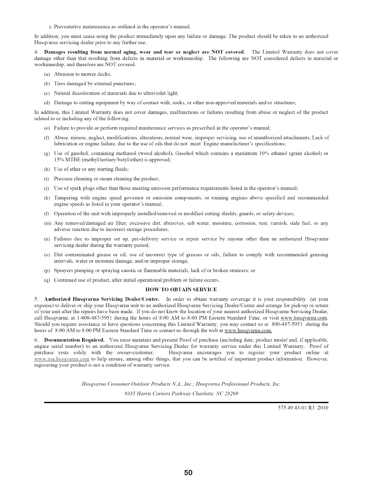
c. Preventative maintenance as outlined in the operator's lnanual.
In addition, you must cease using the product immediately upon any failure or damage. The product should be taken to an authorized
Husqvarna servicing dealer prior to any further use.
4. Damages resulting from normal aging, wear and tear or neglect are NOT covered. The Limited Warranty does not cover
damage other than that resulting froln detects in material or worklnanship. The t\_llowing are NOT considered detects in material or
worklnanship, and therefore are NOT covered.
(a) Abrasion to mower decks;
(b) Tires damaged by external punctures;
(c) Natural discoloration of materials due to ultraviolet light;
(d) Damage to cutting equipment by way of contact with, rocks, or other non-approved materials and/or structures;
In addition, this Limited Warranty does not cover damages, malfunctions or t:ailures resulting from abuse or neglect of the product
related to or including any of the following:
(e) Failure to provide or perforln required lnaintenance services as prescribed in the operator's manual;
(f) Abuse, misuse, neglect, modifications, alterations, normal wear, improper servicing, use of unauthorized attachments, Lack of
lubrication or engine t:ailure, due to the use of oils that do not meet Engine lnanu*:acmrer's specifications;
(g) Use of gasohol, containing lnethanol (wood alcohol). Gasohol which contains a lnaxilnUln 10% ethanol (grain alcohol) or
15% MTBE (lnethyl/tertiary/butyl/ether) is approved;
(h) Use of ether or any starting fluids;
(i) Pressure cleaning or steam cleaning the product;
(i) Use of spark plugs other than those meeting emission perforlnance requirements listed in the operator's manual;
(k) Tampering with engine speed governor or emission components, or running engines above specified and recolnmended
engine speeds as listed in your operator's lnanual;
(1) Operation of the unit with improperly installed/removed or modified cutting shields, guards, or safety devices;
(m) Any removed/damaged air filter, excessive dirt, abrasives, salt water, lnoisture, corrosion, rust, varnish, stale fllel, or any
adverse reaction due to incorrect storage procedures;
(n) Failures due to improper set up, pre-delivery service or repair service by anyone other than an authorized Husqvarna
servicing dealer during the warranty period;
(o) Dirt contalninated grease or oil, use of incorrect type of greases or oils, failure to comply with recolnmended greasing
intervals, water or lnoisture damage, and/or improper storage;
(p) Sprayers pulnping or spraying caustic or flalnmable materials, lack of or broken strainers; or
(q) Continued use of product, after initial operational problem or t:ailure occurs.
HOW TO OBTAIN SERVICE
5. Authorized Husqvarna Servicing Dealer/Center. In order to obtain warranty coverage it is your responsibility (at your
expense) to deliver or ship your Husqvarna unit to an authorized Husqvarna Servicing Dealer/Center and arrange for pick-up or return
of your unit after the repairs have been made. If you do not know the location of your nearest authorized Husqvarna Servicing Dealer,
call Husqvarna, at 1-800-487-5951 during the hours of 8:00 AM to 8:00 PM Eastern Standard Time, or visit www.husqvarna.coln.
Should you require assistance or have questions concerning this Limited Warranty, you may contact us at 800-487-5951 during the
hours of 8:00 AM to 8:00 PM Eastern Standard Time or contact us through the web at www.husqvarna.coln.
6. Documentation Required. You lnust lnaintain and present Proof of purchase (including date, product model and, if applicable,
engine serial nulnber) to an authorized Husqvarna Servicing Dealer for warranty service under this Limited Warranty. Proof of
purchase rests solely with the owner-customer. Husqvarna encourages you to register your product online at
www.asa.h_isqlvama.com to help ensure, alnong other things, that you can be notified of ilnportant product inforlnation. However,
registering your product is not a condition of warranty service.
Husqvarna Consumer Outdoor Products N.A., Inc.; Husqvarna Professional Products, Inc.
9335 Harris' Cornels' Parkway (7_arlotte, NC 28269
575 49 43-01 R3 2010
50
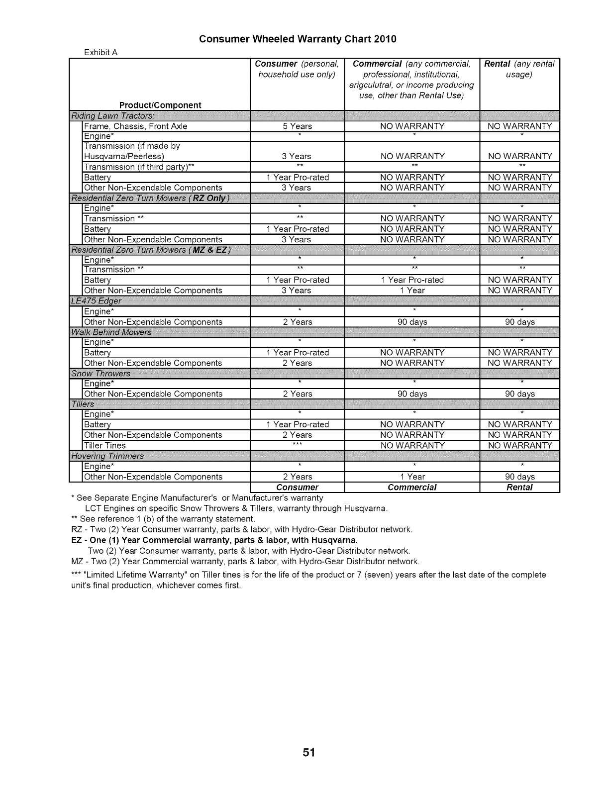
Exhibit A
Consumer Wheeled Warranty Chart 2010
Consumer (personal, Commercial (any commercial, Rental (any rental
household use only) professional, institutional, usage)
arigculutral, or income producing
use, other than Rental Use)
Product/Component
Frame, Chassis, Front Axle 5 Years NO WARRANTY NO WARRANTY
Engine* * * *
Transmission (if made by
Husqvarna/Peerless) 3 Years NO WARRANTY NO WARRANTY
Transmission (if third party) ........
Battery 1 Year Pro-rated NO WARRANTY NO WARRANTY
Other Non-Expendable Components 3 Years NO WARRANTY NO WARRANTY
i_ _ro_rn_ i(_:
Engine* * * *
Transmission .... NO WARRANTY NO WARRANTY
Battery 1 Year Pro-rated NO WARRANTY NO WARRANTY
Engine* * * *
Transmission ** ** ** **
Battery 1 Year Pro-rated 1 Year Pro-rated NO WARRANTY
Other Non-Expendable Components 3 Years 1 Year NO WARRANTY
_}..
IEngine ....
Other Non-Expendable Components 2 Years 90 days 90 days
I .........
_kBe_ MoOrs,.
Engine* * * *
Battery 1 Year Pro-rated NO WARRANTY NO WARRANTY
Other Non-Expendable Components 2 Years NO WARRANTY NO WARRANTY
wets,.
Engine* * * *
Other Non-Expendable Components 2 Years 90 days 90 days
rs,. 11111111111111111111. 11111111111
Engine* * * *
Battery 1 Year Pro-rated NO WARRANTY NO WARRANTY
Other Non-Expendable Components 2 Years NO WARRANTY NO WARRANTY
Tiller Tines *** NO WARRANTY NO WARRANTY
Engine* * * *
Other Non-Expendab e Components 2 Years 1 Year 90 days
Consumer Commercial Rental
• See Separate Engine Manufacturer's or Manufacturer's warranty
LCT Engines on specific Snow Throwers & Tillers, warranty through Husqvarna.
•* See reference 1 (b) of the warranty statement.
RZ - Two (2) Year Consumer warranty, parts & labor, with Hydro-Gear Distributor network.
EZ - One (1) Year Commercial warranty, parts & labor, with Husqvarna.
Two (2) Year Consumer warranty, parts & labor, with Hydro-Gear Distributor network.
MZ - Two (2) Year Commercial warranty, parts & labor, with Hydro-Gear Distributor network.
..... Limited Lifetime Warranty" on Tiller tines is for the life of the product or 7 (seven) years after the last date of the complete
unit's final production, whichever comes first.
51
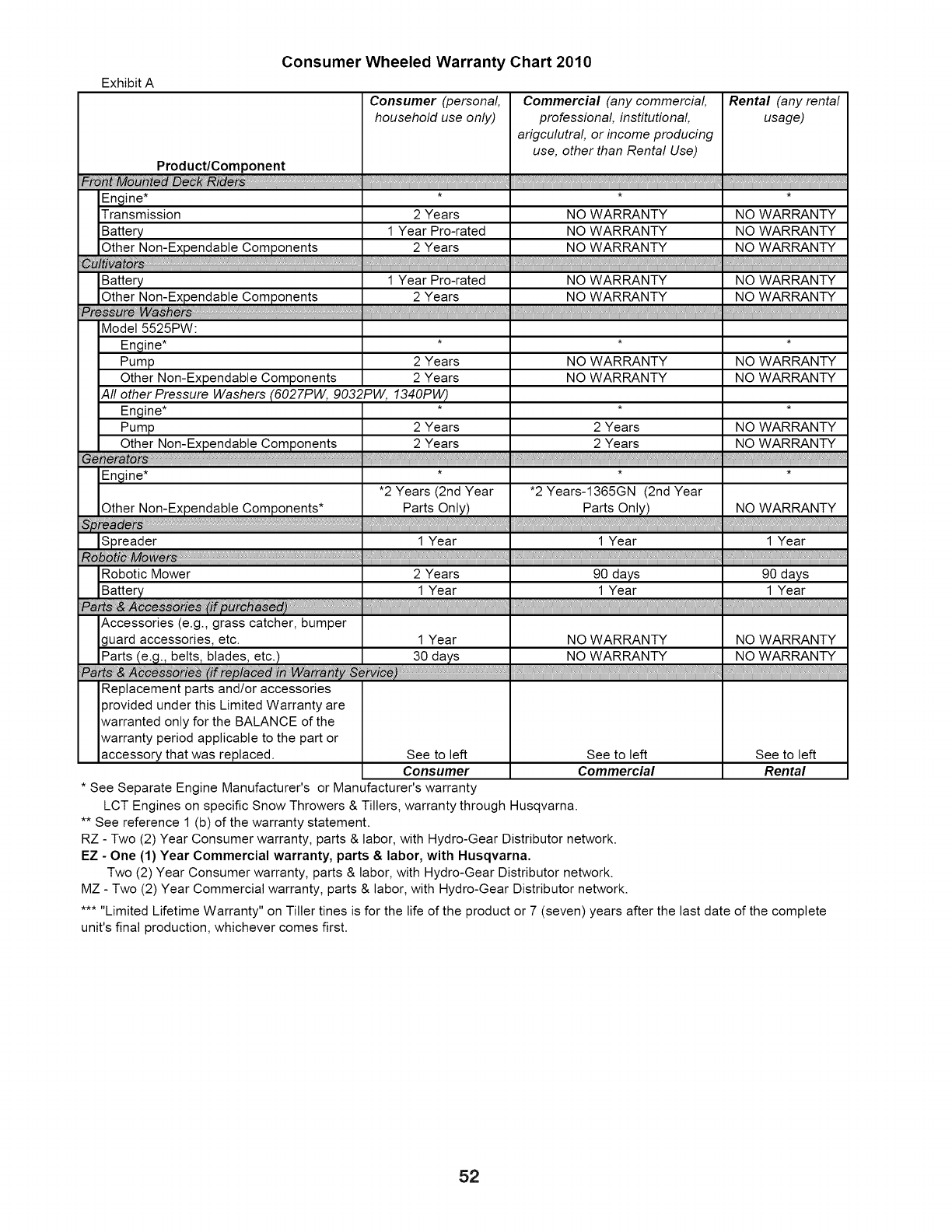
Exhibit A
Consumer Wheeled Warranty Chart 2010
Consumer (personal, Commercial (any commercial, Rental (any rental
household use only) professional, institutional, usage)
arigculutral, or income producing
use, other than Rental Use)
Product/Component
Mo
Engine* * * *
Transmission 2 Years NO WARRANTY NO WARRANTY
Battery 1 Year Pro-rated NO WARRANTY NO WARRANTY
Other Non-Expendable Components 2 Years NO WARRANTY NO WARRANTY
o........
Battery 1 Year Pro-rated NO WARRANTY NO WARRANTY
Other Non-Expendable Components 2 Years NO WARRANTY NO WARRANTY
Model 5525PW:
Engine* * * *
Pump 2 Years NO WARRANTY NO WARRANTY
Other Non-Expendable Components 2 Years NO WARRANTY NO WARRANTY
All other Pressure Washers (6027PW, gO32PW, 1340PW)
Engine* * * *
Pump 2 Years 2 Years NO WARRANTY
Other N°r]::Expendab!e C°mpg!ae!a!s ...... 2 Years 2 Years NO WARRANTY
Engine* * * *
•2 Years (2nd Year *2 Years-1365GN (2nd Year
Other Non-Expendable Components* Parts Only) Parts Only) NO WARRANTY
Spreader 1 Year 1 Year 1 Year
Robotic Mower 2 Years 90 days 90 days
Accessories (e.g., grass catcher, bumper
guard accessories, etc. 1 Year NO WARRANTY NO WARRANTY
Replacement parts and/or accessories
provided under this Limited Warranty are
warranted only for the BALANCE of the
warranty period applicable to the part or
accessory that was replaced. See to left See to left See to left
Consumer Commercial Rental
• See Separate Engine Manufacturer's or Manufacturer's warranty
LCT Engines on specific Snow Throwers & Tillers, warranty through Husqvarna.
•* See reference 1 (b) of the warranty statement.
RZ - Two (2) Year Consumer warranty, parts & labor, with Hydro-Gear Distributor network.
EZ - One (1) Year Commercial warranty, parts & labor, with Husqvarna.
Two (2) Year Consumer warranty, parts & labor, with Hydro-Gear Distributor network.
MZ - Two (2) Year Commercial warranty, parts & labor, with Hydro-Gear Distributor network.
..... Limited Lifetime Warranty" on Tiller tines is for the life of the product or 7 (seven) years after the last date of the complete
unit's final production, whichever comes first.
52

SERVICE NOTES
53

SERVICE NOTES
54

SUGGESTED GUIDE FOR SIGHTING SLOPES FOR SAFE OPERATION
ONLY RIDE UP AND DOWN HILL,
NOT ACROSS HILL
15 DEGREES MAX.
_b ARNING: To avoid serious injury, operate your tractor up and
down the face of slopes, never across the face. Do not mow
slopes greater than 15 degrees. Make turns gradually to prevent
tipping or loss of control. Exercise extreme caution when
changing direction on slopes.
LO
1. Fold this page along dotted line indicated above.
2. Hold page before you so that its left edge is vertically parallel to a tree
trunk or other upright structure.
3. Sight across the fold in the direction of hill slope you want to measure.
4. Compare the angle of the fold with the slope of the hill.

01.12.11 SR Husqvarna Printed in the U.S.A.

®
O7O
Manual de Due6os
Esta maquina puede utilizar gasolina con un contenido de hasta el 10% de etanol (EIO).
El uso de una gasolina que supere el 10% de etanol (EIO) anulara la garantia del producto.
532 44 13-61 Rev. 1
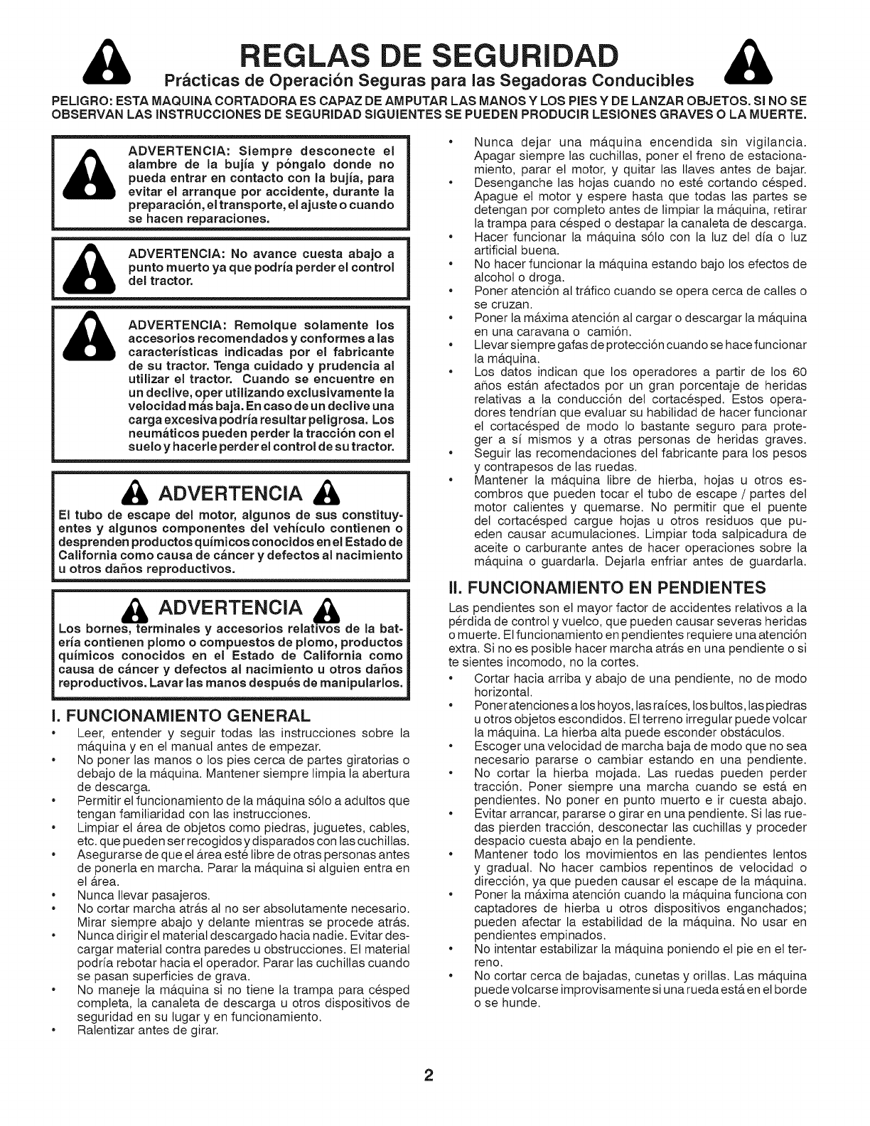
REGLAS DE SEGURIDAD &
PractJcas de Operacion Seguras para las Segadoras Conducibles
PEUGRO: ESTA MAQUINA CORTADORA ES CAPAZ DE AM PUTAR LAS MANOS Y LOS PiES Y DE LANZAR OBJETOS. SJNO SE
OBSERVAN LAS INSTRUCCIONES DE SEGURIDAD SJGUIENTES SE PUEDEN PRODUCIR LESIONES GRAVES OLA MUERTE.
ADVERTENCJA: Siempre desconecte el
alambre de la bujia y p6ngalo donde no
pueda entrar an contacto con la bujJa, para
evitar el arranque por accidente, durante la
preparaci6n, el transporte, el ajuste o cuando
se hacen reparaciones.
ADVERTENCIA: No avance cuesta abajo a
punto muerto ya qua podrJa perder el control
del tractor.
ADVERTENCIA: RemoJque soJamente los
accesorios recomendados yconformes alas
caracterJstJcas indJcadas por el fabrJcante
de su tractor. Tenga cuidado y prudencia al
utJlizar el tractor. Cuando se encuentre an
un declive, oper utilizando exclusivamente la
velocidad m6s baja. En caso de un declive una
carga excesJva podrJa resultar peligrosa. Los
neum_tJcos pueden perder la tracci6n con el
suelo y hacerle perder el control de su tractor,
ADVERTENCIA
El tubo de escape del motor, aJgunos de sus constJtuy-
antes y algunos componentes del vehiculo contJenen o
desprenden productos quJmicos conocidos an eJEstado de
California como causa de c6ncer y defectos al nacimiento
uotros da6os reproductivos,
ADVERTENCIA
Los bornes, terminales y accesorios relatJvos de la bat=
aria contJenen plomo o compuestos de pJomo, productos
quJmicos conocidos an el Estado de California como
causa de c6ncer y defectos al nacimJento u otros daflos
reproductivos, Lavar las manos despu6s de manJpularlos,
I. FUNCIONAMIENTO GENERAL
•Leer, entender y seguir todas las instrucciones sobre la
m&quina yen el manual antes de empezar.
• No poner las manos o los pies cerca de partes giratorias o
debajo de la m&quina. Mantener siempre limpia la abertura
de descarga.
• Permitir el funcionamiento de la m&quina s61o a aduttos que
tengan familiaridad con las instrucciones.
• Limpiar et &rea de objetos como piedras, juguetes, cables,
etc. que pueden ser recogidos y disparados con las cuchiltas.
• Asegurarse de que el &rea este libre de otras personas antes
de ponerla en marcha. Parar la m&quina si alguien entra en
el &rea.
• Nunca Ilevar pasajeros.
• No cortar marcha atr&s al no ser absolutamente necesario.
Mirar siempre abajo y delante mientras se procede atr&s.
• Nunca dirigir et material descargado hacia nadie. Evitar des-
cargar material contra paredes u obstrucciones. Et material
podria rebotar hacia el operador. Parar las cuchillas cuando
se pasan superficies de grava.
• No maneje la m&quina si no tiene la trampa para cesped
compteta, la canaleta de descarga u otros dispositivos de
seguridad en su lugar yen funcionamiento.
• Ralentizar antes de girar.
* Nunca dejar una m&quina encendida sin vigilancia.
Apagar siempre las cuchiltas, porter et freno de estaciona-
miento, parar et motor, y quitar las Ilaves antes de bajar.
* Desenganche las hojas cuando no este cortando cesped.
Apague el motor y espere hasta que todas las partes se
detengan por completo antes de limpiar la m&quina, retirar
la trampa para cesped o destapar la canateta de descarga.
* Hacer funcionar la m&quina s6to con la luz det dia o luz
artificial buena.
* No hacer funcionar la m&quina estando bajo los efectos de
alcohol o droga.
* Poner atenci6n al tr&fico cuando se opera cerca de calles o
se cruzan.
* Poner la m&xima atenci6n al cargar o descargar la m&quina
en una caravana o cami6n.
* Llevar siempre gafas de protecci6n cuando se hace funcionar
la m&quina.
* Los datos indican que los operadores a partir de los 60
aflos est&n afectados por un gran porcentaje de heridas
relativas a ta conducci6n det cortacesped. Estos opera-
dores tendr[an que evaluar su habilidad de hacer funcionar
el cortacesped de modo Io bastante seguro para prote-
ger a si mismos y a otras personas de heridas graves.
* Seguir las recomendaciones det fabricante para los pesos
y contrapesos de las ruedas.
* Mantener la m&quina libre de hierba, hojas u otros es-
combros que pueden tocar et tubo de escape /partes del
motor calientes y quemarse. No permitir que el puente
del cortacesped cargue hojas u otros residuos qua pu-
eden causar acumutaciones. Limpiar toda salpicadura de
aceite o carburante antes de hacer operaciones sobre la
m&quina o guardarla. Dejarla enfriar antes de guardarla.
II. FUNCIONAMIENTO EN PENDIENTES
Las pendientes son el mayor factor de accidentes relativos a la
p@dida de control y vuelco, qua pueden causar severas heridas
o muerte. Etfuncionamiento en pendientes requiere una atenci6n
extra. Si no es posibte hacer marcha atr&s en una pendiente o si
te sientes incomodo, no la cortes.
* Cortar hacia arriba y abajo de una pendiente, no de modo
horizontal.
* Poner atenciones a los hoyos, las raices, los buttos, las piedras
u otros objetos escondidos. Et terreno irregular puede volcar
la m&quina. La hierba alta puede esconder obst&cutos.
* Escoger una vetocidad de marcha baja de modo que no sea
necesario pararse o cambiar estando en una pendiente.
* No cortar la hierba mojada. Las ruedas pueden perder
tracci6n. Poner siempre una marcha cuando se est& en
pendientes. No poner en punto muerto e ir cuesta abajo.
* Evitar arrancar, pararse o girar en una pendiente. Si las rue-
das pierden tracci6n, desconectar las cuchitlas y proceder
despacio cuesta abajo en ta pendiente.
* Mantener todo los movimientos en las pendientes lentos
y gradual. No hacer cambios repentinos de vetocidad o
direcci6n, ya que pueden causar el escape de la m&quina.
* Poner ta m&xima atenci6n cuando la m&quina funciona con
captadores de hierba u otros dispositivos enganchados;
pueden afectar la estabilidad de la m&quina. No usar en
pendientes empinados.
* No intentar estabilizar la m&quina poniendo et pie en et ter-
reno.
* No cortar cerca de bajadas, cunetas y orillas. Las m&quina
puede volcarse improvisamente si una rueda est& en el borde
o se hunde.
2
&
II1. NINOS
REGLAS DE SEGURIDAD
Practicas de Operacibn Seguras para las Segadoras Conducibles
Si et operador no pone atenci6n a la presencia de los niflos pueden
ocurrir accidentes tr&gicos. Los niflos a menudo est&n atraidos
por la m&quina y tas actividad de cortar. No dar por hecho de que
los niflos se queden adonde estaban la Ottima vez que los vistes.
Mantener los niflos fuera del &rea de corte y vigilados pot
un adulto responsabte que no sea el operador.
Estar alerta y apagar la m&quina si un niflos entra en el &rea.
* Antes y durante ta marcha atr&s, mirar adelante y abajo para
ver si hay niflos pequeflos.
* Nunca Ilevar niflos, inctuso si hay las cuchillas apagadas.
Podrian caer y herirse seriamente o interferir con el funcio-
namiento seguro de la m&quina, los niflos que se han Ilevado
precedentemente pueden aparecer de pronto en el &rea de
corte por otro paseo y ser atropetlados o tumbados por la
m&quina.
* Nunca dejar que los niflos manipulen la m&quina.
* Tener et m&ximo cuidado cuando se acerca a cantos ciegos,
arbustos, &rboles u otros objetos que pueden impedir la vista
de niflos.
IV. REIVIOLQUE
•Remolcar s6to con una maquina que tenga un gancho dis-
eflado para remolcar. Enganchar et equipo o remolcar s6to
en el punto dispuesto al efecto.
Seguir las recomendaciones det productor con respecto a los
limites del equipo por remolcar y et remotque en pendientes.
Nunca permitir que niflos u otras personas esten dentro det
equipo por remolcar.
En pendientes, el peso det equipo remotcado puede causar
la perdida de tracci6n y la perdida de control.
Viajar despacio y dejar m&s distancia para frenar.
V. SERVlCIO
MANIPULACION SEGURA DE LA GASOLINA
OPERACIONES DE SERVIClO GENERALES
•Nunca hacer funcionar la m&quina en un &rea cerrada.
• Mantener todas las tuercas y pernos apretados para asegu-
rarse de que trabaja en condiciones seguras.
• Nunca modificar los dispositivos de seguridad. Controlar su
correcto funcionamiento regutarmente.
• Mantener la m&quina libre de hierba, hojas u otros re-
siduos acumutados. Limpiar las salpicaduras de aceite
o carburante y quitar cualquier cosa mojada con carbu-
rante. Dejar que ta m&quina se enfr[e antes de guardarta.
• Si se golpea un objeto ajeno, hay que pararse e inspeccionar
la m&quina. Reparar, si es necesario, antes de volver a poner
en marcha.
• Nunca hacer ningQn ajuste o reparaci6n con et motor en
funci6n.
• Verifique los componentes de la trampa para cesped y la
canaleta de descarga con frecuencia y sustituya con repues-
tos recomendados por et fabricante cuando sea necesario.
• Las cuchillas det cortacesped son afiladas. Envolv-
er la cuchitta, ponerse guantes y poner la m&xima
atenci6n cuando se hacen operaciones en elias.
• Controlar elfuncionamiento detfreno frecuentemente. Ajustar
y hacer las operaciones de mantenimiento cuando eso sea
necesario.
• Mantener y sustituir las etiquetas de seguridad e instrucci6n,
cuando sea necesario.
• Asegurarse de que el &rea este libre de otras personas antes
de ponerla en marcha, para la m&quina si alguien entra en
el &rea.
• Nunca Ilevar pasajeros.
Para evitar heridas personales o daflos alas cosas, poner el
m&ximo cuidado a la hora de manipular la gasolina. La gasolina
es extremamente inftamabte y los vapores son explosivos.
Apagar todos los cigarritlos, cigarros, pipas y otras fuentes
de ignici6n.
Usar s61o contenedores para gasolina aprobados.
Nunca quitar el tap6n de la gasotina o afladir carburante
con el motor en marcha, dejar enfriar et motor antes det
abastecimiento de la gasolina.
Nunca abastecer la m&quina al interior de un local.
Nunca guardar la m&quina o el contenedor del carbu-
rante donde haya una llama abierta, chispas o una luz
piloto como un calentador de agua u otros dispositivos.
Nunca tlenar los contenedores al interior de un vehiculo o en
una caravana o cami6n recubiertos con un forro de pl&stico.
Cotocar siempre los contenedores en et terreno lejos det
vehiculo cuando se est& tlenando.
Quitar et equipo de gas det cami6n o caravana y abastecerto
en et terreno. Si no es posible, abastecer dicho equipo con un
contenedor port&til, m&s bien que de un surtidor de gasolina.
Mantener la boquilla a contacto del borde del dep6sito de
carburante o la abertura det contenedor durante toda la
operaci6n de abastecimiento. No utilizar un dispositivo con
boquilla cerrada-abierta.
Si se vierte carburante sobre la ropa, cambiarse la ropa
inmediatamente.
Nunca Ilenar el dep6sito m&s de Io debido. Volver a colocar
el tap6n det gas y cerrar de modo firme.
No cortar marcha atr&s at no ser absolutamente necesario.
Mirar siempre abajo y detante mientras se procede atr&s.
Nunca Ilevar niflos, incluso si hay las cuchillas apagadas.
Podrian caer y herirse seriamente o interferir con el funcio-
namiento seguro de la m&quina, los niflos que se han tlevado
precedentemente pueden aparecer de pronto en et &rea de
corte .por otto paseo y ser atropetlados o tumbados pot la
m&qutna.
•Mantener los niflos fuera det &rea de corte y vigitados por
un adutto responsabte que no sea el operador.
•Estar alerta y apagar la m&quina si un niflos entra en et &rea.
•Antes y durante la marcha atr&s, mirar adetante y abajo para
ver si hay niflos pequeflos.
•Cortar hacia arriba y abajo de una pendiente (15 ° M&x), no
de modo horizontal.
•Escoger una velocidad de marcha baja de modo que no sea
necesario pararse o cambiar estando en una pendiente.
•Evitar arrancar, pararse o girar en una pendiente. Si las rue-
das pierden tracci6n, desconectar las cuchitlas y proceder
despacio cuesta abajo en la pendiente.
•Si la m&quina se para mientras va cuesta arriba, desconectar
las cuchillas, poner la marcha atr&s y ir hacia atr&s despacio.
•No girar estando en pendientes si no es necesario, y luego
girar despacio y gradualmente cuesta abajo, si es posibte.
3

ESPECIFICACIONES DEL PRODUCTO
Capacidad y Tipo 4.0 Gatones
de gasolina: Regular Sin Plomo
Tipo de Aceite: SAE 30 (Sobre 32°F/0°0)
(API-SG-SL) SAE 5W30 (Debajo 32°F/0°0)
Capacidad de Con filtro: 64 oz.
petr6teo: Sin filtro: 52 oz.
Buj{a: NGK BPR4ES
(Abertura: .030")
Vetocidad de Detante: 0 - 5.2
Recorrido (MPH): Marcha Atr&s: 0 -2.9
Sistema de Carga: 15 Amps @ 3600 RPM
Bateria: Amp/H r: 28
Min. CCA: 230
Case Size: U1R
Torsi6n del Perno
de la Cuchilla: 45-55 Ft. Lbs.
FELICITACIONES por la compra de su tractor. Ha sido disehado,
ptanificado y fabricado para darle la mejor confiabilidad y et mejor
rendimiento posibte.
En et caso de que se encuentre con cualquier problema que no
pueda solucionar f&citmente, haga el favor de ponerse en con-
tacto con un centro de servicio o con un otro centro de servicio
cualificado. Cuenta con tecnicos bien capacitados y competen-
tes y con tas herramientas adecuadas para darle servicio o para
reparar este tractor.
Haga el favor de leer y de guardar este manual. Estas instrucciones
le permitir&n montar y mantener su unidad en forma adecuada.
Siempre observe las "REGLAS DE SEGURIDAD."
RESPONSABILIDADES DEL CLIENTE
•Lea y observe las reglas de seguridad.
Siga un programa regular de mantenimiento, cuidado y uso
de su tractor.
• Siga las instrucciones descritas en las secciones "Manten-
imiento" y 'Atmacenamiento" de este manual.
ADVERTENCIA: Este tractor viene equipado con un motor
de combusti6n interna y no se debe usar sobre, o cerca, de un
terreno no desarrotlado cubierto de bosques, de arbustos o de
cesped, o menos que et sistema de escape del motor venga
equipado con un amortiguador de chispas que cumpta con tas
leyes locales o estatales (si existen). Si se usa un amortiguador
de chispas, el operador debe mantenerlo en condiciones de
trabajo eficientes.
En et estado de California, la ley exige to anterior (Secci6n 4442
del "California Public Resources Code"). Otros estados pueden
contar con otras leyes parecidas. Las leyes federales se aptican
en la tierras federates.
Su centro de Servicio m&s cercano tiene disponibte amortigua-
dotes de chispas para et silenciador.
TABLA DE MATERIAS
REGLAS DE SEGURIDAD ................................................... 2-3
ESPECIFICACIONES DEL PRODUCTO ................................ 4
RESPONSABILIDADES DEL CLIENTE ................................. 4
MONTAJE/PRE OPERACI6N .............................................. 5=9
OPERACION ..................................................................... 10-16
TABLA DEL MANTENIMIENTO ........................................... 17
MANTENIMIENTO ............................................................ 17-20 4
SERVICIO Y AJUSTES .................................................... 21-25
ALMACENAMIENTO ............................................................. 26
IDENTIFICACI6N DE PROBLEMAS ............................... 27-28
PIEZAS DE REPARACI6N ............................................... 29-42
TRANSEJE ............................................................................ 43
MOTOR ............................................................................. 44-48
GARANTiA ........................................................................ 49-52
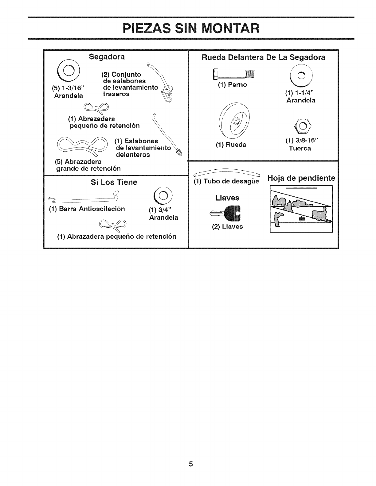
PIEZAS SIN MONTAR
(5) 1=3/16"
Arandela
Segadora
(2) Conjunto
de eslabones \\
de levantamiento _
traseros
(1) Abrazadera
pequeSo de retenci6n _
\\
(1) Eslabones _\
______-__ de levantamiento
delanteros
(5) Abrazadera
grande de retenci6n
Si Los Tiene
(1) Barra Antioscilaci6n G
(1) 3/4"
Arandela
(1) Abrazadera pequeSo de retenci6n
Rueda Delantera De La Segadora
E
(1) Perno
(1) Rueda
(I) 1-1/4"
Arandela
©
(1) 3/8=16"
Tuerca
(1) Tubo de desagQe
Llaves
lr,',I
(2) Llaves
Hoja de pendiente
5
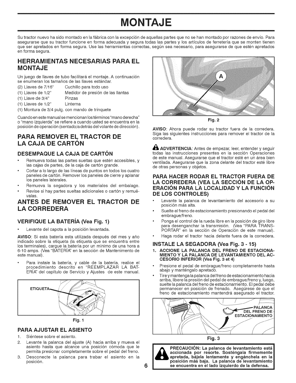
MONTAJE
Su tractor nuevo ha sido montado en la f&brica con la excepci6n de aquetlas partes que no se han montado por razones de envfo. Para
asegurarse que su tractor funcione en forma adecuada y segura todas las partes y los arficulos de ferreteria que se monten tienen
que ser apretados en forma segura. Use las herramientas correctas, seg0n sea necesario, para asegurarse de que esten apretados
en forma segura.
HERRAMIENTAS NECESARIAS PARA EL
MONTAJE
Un juego de Ilaves de tubo facilitar& el montaje. A continuaci6n
se enumeran los tamaflos de las Ilaves est&ndar.
(2) Llaves de 7/16" Cuchitlo para todo uso
(1) Llaves de 1/2" Medidor de presi6n de las Ilantas
(1) Llave de 3/4" Pinzas
(1) Llaves de 1/2" Linterna
(1) Montura de 3/4 pulg. con mando de trinquete
Cuando en este man ual se mencionan los terminos"mano derecha"
o "mano izquierda" se refiere a cuando usted se encuentra en la
posici6n de operaci6n (sentado/a detr&s del volante de direcci6n).
PARA REMOVER EL TRACTOR DE
LA CAJA DE CARTON
DESEMPAQUE LA CAJA DE CARTON
Remueva todas las partes suettas que esten accesibtes, y
las cajas de partes, de la caja de cart6n grande.
Cortar a Io largo de las lineas de puntos en todos los cuatro
paneles de cart6n. Remover los panetes de cierre y aptanar
los paneles laterales.
Remueva la segadora y los materiales det embalage.
Revise si hay partes sueltas adicionales o cart6n y remue-
valas.
ANTES DE REMOVER EL TRACTOR DE
LA CORREDERA
VERIFIQUE LA BATERiA (Vea Fig. 1)
Levante det capota a la posici6n levantada.
AVISO: Si esta bateria esta utilizada despues del mes y aflo
indicado sobre la etiqueta (ta etiqueta que se encuentra entre
los terminates), cargue la bateria por un minimo de una hora a
6-10 amps. (Vea "BATER[A:' en la secci6n de Mantenimento de
este manual).
•Para instale la bateria, y cable de la bateria, realice et
procedimiento descrito en "REEMPLAZAR LA BAT-
ERIA:' det capituto de Servicio y Ajustes de este manual.
m
Fig. 1
PARA AJUSTAR EL ASIENTO
1. Sientese sobre el asiento.
2. Levante la palanca del ajuste (A) hacia arriba y mueva el
asiento hasta que atcance una posici6n c6moda que le
permita presionar comptetamente sobre et pedal det freno.
3. Desconecte la palanca para trabar et asiento en la
posici6n.
Fig. 2
AViSO: Ahora puede rodar su tractor fuera de la corredera.
Siga las siguientes instrucciones para remover et tractor de la
corredera.
ADVERTENCIA: Antes de empezar, leer, entender y seguir
todas las instrucciones presentes en ta secci6n Operaciones
de este manual. Asegurarse que et tractor este en un &rea bien
ventilada. Asegurarse que la zona detante det tractor este libre
de otras personas y objetos.
PARA HACER RODAR EL TRACTOR FUERA DE
LA CORREDERA (VEA LA SECClON DE LA OP=
ERAClON PARA LA LOCALIDAD Y LA FUNClON
DE LOS CONTROLES)
•Levante la palanca de levantamiento det accesorio a su
posici6n m&s alta.
• Suelte el freno de estacionamiento presionando et pedal det
embrague/freno.
• Ponga el control de la rueda libre en ta posici6n de giro libre
para desenganchar la transmisi6n. (Vea "PARA TRANS-
PORTAR" en la secci6n de Operaci6n de este manual).
• Haga rodar et tractor hacia delante fuera de la corredera.
INSTALE LA SEGADORA (Vea Fig. 3 = 15)
1. ACCIONE LA PALANCA DEL FRENO DE ESTACIONA=
MIENTO Y LA PALANOA DE LEVANTAMIENTO DEL AC-
CESORIO iNFERiOR (Vea Fig. 3 et 4)
•Presione el pedal de embrague/freno comptetamente hasta
abajo y mantengato apretado.
•Tire y mantenga la palanca del freno de estacionamiento hacia
arriba, libere la presi6n del pedal de embrague/freno y, luego,
suette la palanca del freno de estacionamiento. El pedal debe
permanecer en posici6n de frenado. Aseg0rese de que et
freno de estacionamiento mantendr& asegurado el tractor.
6
Fig. 3
_PRECAUCION: La palanca de levantamiento est_
accionada pot reaorte. Sost6ngala firmemente
apretada, b_jela lentamente y eng_nchela an la
posici6n m_s baja. La palanca de levantamiento
se encuentra en el lado izquierdo de la defensa.
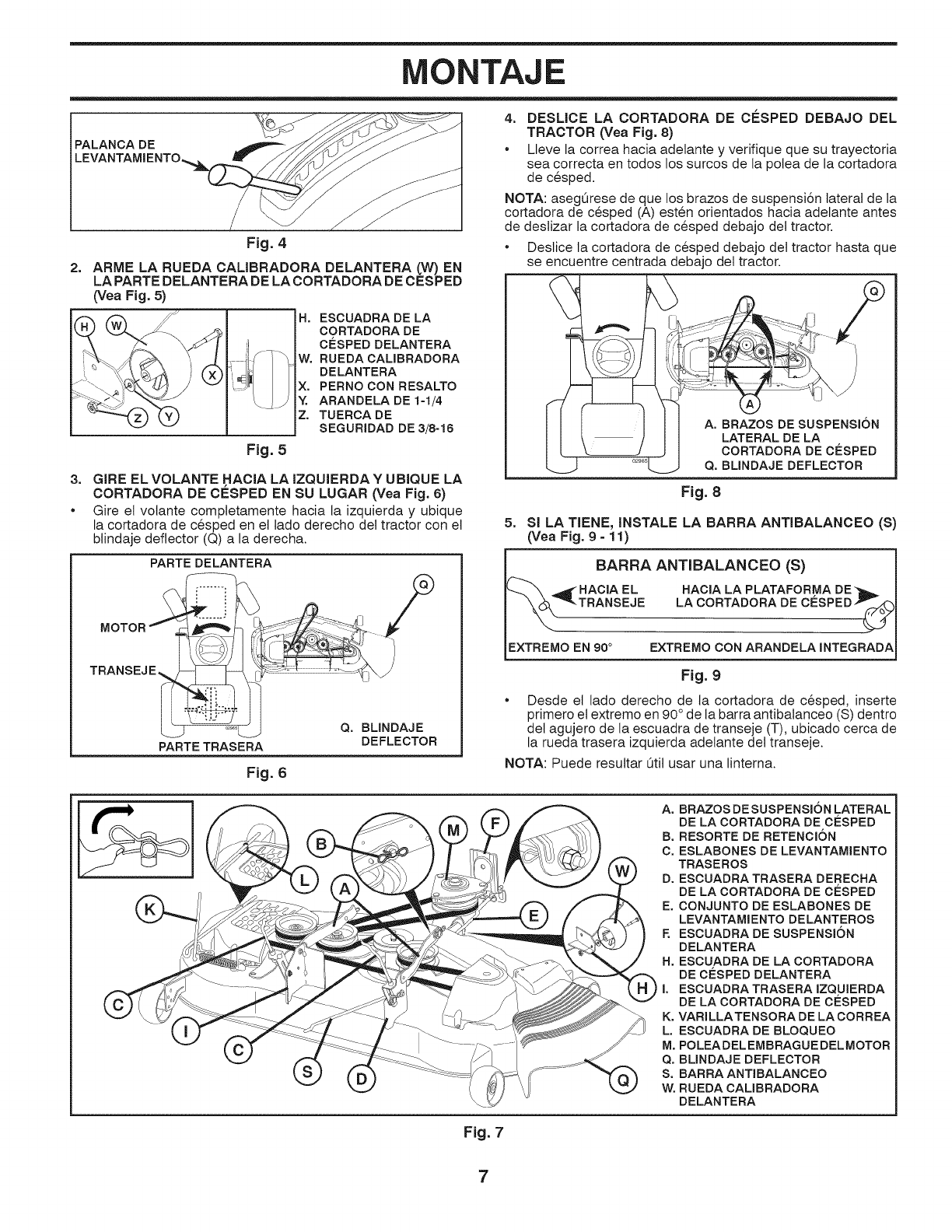
MONTAJE
PALANCA DE
LEVANTAM IENTO,
2=
Fig. 4
ARIVlE LA RUEDA CALIBRADORA DELANTERA (W) EN
LA PARTE DELANTERA DE LA CORTADORA DE CESPED
(Vea Fig, 5)
H, ESCUADRA DE LA
CORTADORA DE
CO:SPEDDELANTERA
W. RUEDA CALIBRADORA
DELANTERA
X. PERNO CON RESALTO
Y. ARANDELA DE 1=1/4
Z. TUERCA DE
SEGURIDAD DE3/8=18
Fig. 5
3. GIRE ELVOLANTE HACIA LA IZQUIERDAY UBIQUE LA
CORTADORA DE CESPED EN SU LUGAR (Vea Fig. 6)
•Gire et votante completamente hacia la izquierda y ubique
la cortadora de cesped en et lado derecho del tractor con et
btindaje deflector (Q) a la derecha.
4. DESLICE LA CORTADORA DE C_=SPED DEBAJO DEL
TRACTOR (Vea Fig. 8)
•Lleve la correa hacia adelante y verifique que su trayectoria
sea correcta en todos los surcos de la polea de la cortadora
de cesped.
NOTA: asegQrese de que los brazos de suspensi6n lateral de la
cortadora de cesped (A) esten orientados hacia adelante antes
de deslizar la cortadora de cesped debajo del tractor.
• Deslice la cortadora de cesped debajo det tractor hasta que
se encuentre centrada debajo det tractor.
-- m
A. BRAZOS DE SUSPENSION
LATERAL DE LA
CORTADORA DE CESPED
Q. BLINDAJE DEFLECTOR
Fig. 8
5. SI LA TIENE, INSTALE LA BARRA ANTIBALANCEO (S)
(Vea Fig. 9 - 11)
PARTE DELANTERA
TRANSEJE
PARTETRASERA
Fig. 6
Q. BLINDAJE
DEFLECTOR
BARRA ANTIBALANCEO (S)
_ HACIA EL HACIA LA PLATAFORMA DE_b _
TRANSEJE LA CORTADORA DE CESPED_._
EXTREMO EN 90° EXTREMO CONARANDELA INTEGRADA
Fig. 9
Desde et lado derecho de la cortadora de cesped, inserte
primero el extremo en 90° de la barra antibalanceo (S) dentro
det agujero de la escuadra de transeje (T), ubicado cerca de
la rueda trasera izquierda adetante det transeje.
NOTA: Puede resuttar [3til usar una linterna.
A. BRAZOSDESUSPENSI6N LATERAL
DE LA CORTADORA DE CESPED
B. RESORTE DE RETENCION
C. ESLABONES DE LEVANTAMIENTO
TRASEROS
D. ESCUADRA TRASERA DERECHA
DE LA CORTADORA DE CESPED
E. CONJUNTO DE ESLABONES DE
LEVANTAMIENTO DELANTEROS
E ESCUADRA DE SUSPENSION
DELANTERA
H. ESCUADRA DE LA CORTADORA
DE CO:SPED DELANTERA
I. ESCUADRATRASERA IZQUIERDA
DE LA CORTADORA DE CESPED
K. VARILLATENSORA DE LA CORREA
L, ESCUADRA DE BLOQUEO
M, POLEADEL EMBRAGUE DELMOTOR
Q. BLINDAJE DEFLECTOR
S. BARRA ANTIBALANCEO
W. RUEDA CALIBRADORA
DELANTERA
Fig. 7
7
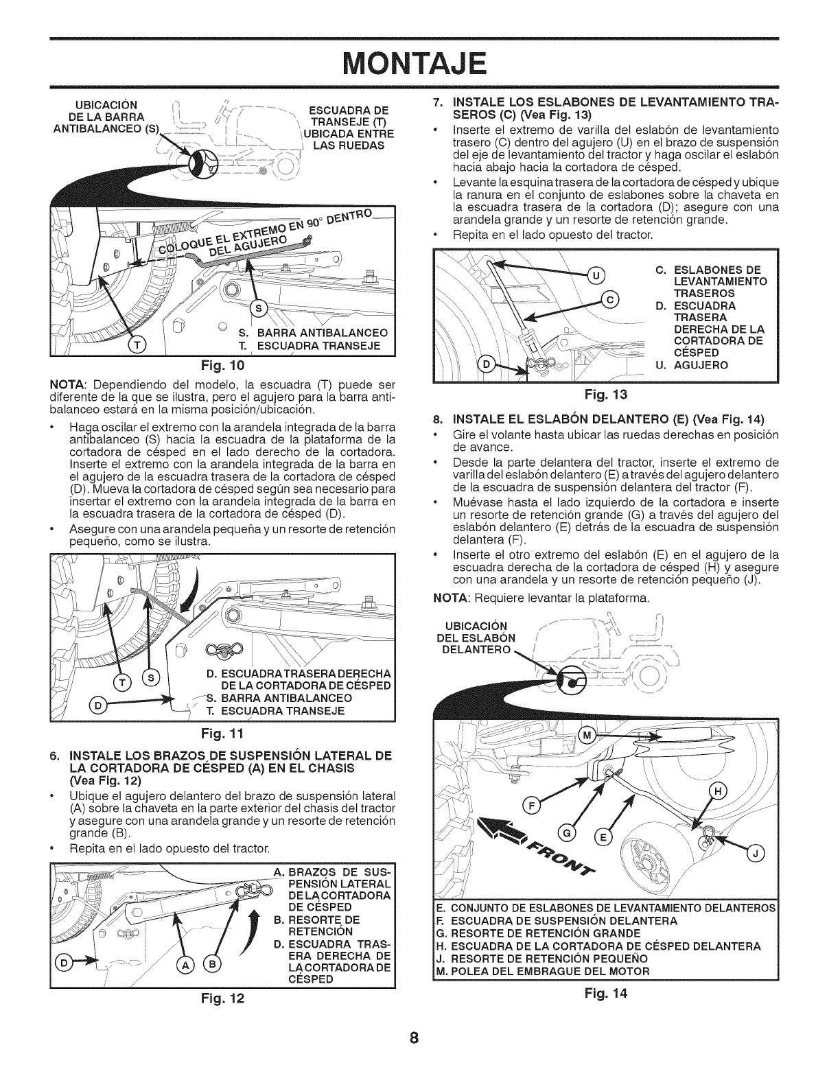
MONTAJE
UBICACI6N ESCUADRA DE
DE LA BARRA
ANTIBALANCEO (S), 2:1:, TRANSEJE (T)
UBICADA ENTRE
.......................LAS RUEDAS
7. INSTALE LOS ESLABONES DE LEVANTAMIENTO TRA-
SEROS (C) (Vea Fig. 13)
*Inserte el extremo de varilla det eslab6n de levantamiento
trasero (O) dentro del agujero (U) en et brazo de suspensi6n
del eje de levantamiento del tractor y haga oscilar et estab6n
hacia abajo hacia la cortadora de cesped.
Levante la esquinatrasera de la cortadora de cesped y ubique
la ranura en et conjunto de estabones sobre la chaveta en
la escuadra trasera de la cortadora (D); asegure con una
arandela grande y un resorte de retenci6n grande.
Repita en et lado opuesto det tractor.
Fig. 10
NOTA: Dependiendo det modelo, la escuadra (T) puede ser
diferente de la que se ilustra, pero et agujero para la barra anti-
balanceo estar& en la misma posici6n/ubicaci6n.
Haga oscilar el extremo con la arandeta integrada de la barra
antibalanceo (S) hacia la escuadra de la ptataforma de la
cortadora de cesped en et lado derecho de la cortadora.
Inserte et extremo con ta arandeta integrada de la barra en
et agujero de la escuadra trasera de la cortadora de cesped
(D). Mueva la cortadora de cesped segOn sea necesario para
insertar el extremo con la arandela integrada de la barra en
la escuadra trasera de la cortadora de cesped (D).
Asegure con una arandeta peque_a y un resorte de retenci6n
pequeho, como se ilustra.
lJ
1 ¢):
D. ESCUADRATRASERADERECHA
DELA CORTADORADECESPED
f-S. BARRA ANTIBALANOEO
/
, • ESOUADRATRANSEJE
Fig. 11
6. INSTALE LOS BRAZOS DE SUSPENSK)N LATERAL DE
LA CORTADORA DE ClaSPED (A) EN EL CHASIS
(Vea Fig. 12)
•Ubique et agujero detantero det brazo de suspensi6n lateral
(A) sobre la chaveta en ta parte exterior del chasis del tractor
y asegure con una arandeta grande y un resorte de retenci6n
grande (B).
• Repita en et lado opuesto del tractor.
f£_ _ _ A. BRAZOS DE SUS-
/"_'_-__2 PENSION LATERAL
e,_t' 4_ _ . ..... ..... DELACORTADORA
"" ' ........... B.'/£''' RESORTE DE
DE CESPED
RETENOION
D. ESOUADRA TRAS-
ERA DEREOHA DE
LA CORTADORADE
, CESPED
Fig. 12
C. ESLABONES DE
LEVANTAMIENTO
TRASEROS
D. ESCUADRA
TRASERA
DEREOHA DE LA
OORTADORADE
CESPED
U. AGUJERO
Fig. 13
8. JNSTALE EL ESLABON DELANTERO (E) (Vea Fig. 14)
•Gire el votante hasta ubicar las ruedas derechas en posici6n
de avance.
Desde la parte delantera det tractor, inserte et extremo de
varilla del estab6n delantero (E) a traves det agujero detantero
de la escuadra de suspensi6n detantera det tractor (F).
Muevase hasta el lado izquierdo de la cortadora e inserte
un resorte de retenci6n grande (G) a traves del agujero del
estab6n detantero (E) detr&s de la escuadra de suspensi6n
detantera (F).
• Inserte el otro extremo del eslab6n (E) en et agujero de la
escuadra derecha de la cortadora de cesped (H) y asegure
con una arandeta y un resorte de retenci6n pequeflo (J).
NOTA: Requiere levantar la plataforma.
.......................i_, _,.
UBICACI6N ," .... "_:_,
DEL ESLABON /...................
DELANTERO ,,..........._ oo/...............................
_J
E. CONJUNTO DE ESLABONES DE LEVANTAMIENTO DELANTEROS
F. ESCUADRA DE SUSPENSI6N DELANTERA
G. RESORTE DE RETENCI6N GRANDE
H. ESCUADRA DE LA CORTADORA DE CESPED DELANTERA
J. RESORTE DE RETENCION PEQUENO
M. POLEA DEL EMBRAGUE DEL MOTOR
Fig. 14
8
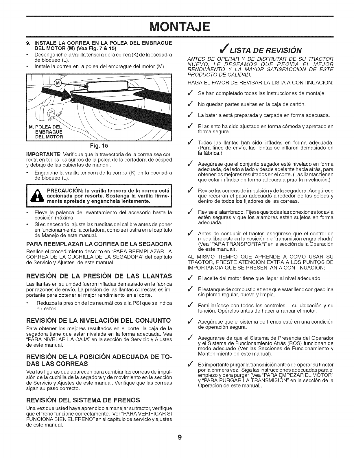
MONTAJE
9. INSTALE LA CORREA EN LA POLEA DEL EMBRAGUE
DEL MOTOR (M) (Vea Fig. 7&15)
•Desenganche lavarillatensora de la correa (K) de la escuadra
de bloqueo (L).
Instale la correa en la polea det embrague det motor (M)
M. POLEA DEL
EMBRAGUE
DEL MOTOR
Fig. 15
IMPORTANTE: Verifique que la trayectoria de la correa sea cor-
recta en todos los surcos de la potea de la cortadora de cesped
y debajo de las cubiertas de mandril.
Enganche ta varilla tensora de la correa (K) en la escuadra
de btoqueo (L).
&m
PRECAUCI6N: la varilla tensora de la correa est_ I
accionada por resorte. Sostenga la varilla firme-
mente apretada yeng_nchela lentamente. J
®
®
Eleve la palanca de levantamiento det accesorio hasta la
posici6n m&xima.
Si es necesario, ajuste las rueditas det calibre antes de poner
en funcionamiento ta cortadora, como se ilustra en et capituto
de Manejo de este manual.
PARA REEMPLAZAR LA CORREA DE LA SEGADORA
Realice el procedimiento descrito en "PARA REEMPLAZAR LA
CORREA DE LA CUCHILLA DE LA SEGADORA:' det capituto
de Servicio y Ajustes de este manual.
REVISION DE LA PRESi0N DE LAS LLANTAS
Las llantas en su unidad fueron infladas demasiado en la fa.brica
por razones de envio. La presi6n de las Ilantas correctas es im-
portante para obtener el mejor rendimiento en et corte.
Reduzca la presi6n de los neum&ticos a la PSI que se indica
en estos.
REVISION DE LA NIVELACION DEL CONJUNTO
Para obtener los mejores resuttados en el corte, la caja de la
segadora tiene que estar nivetada en la forma adecuada. Vea
"PARA NIVELAR LA CAJA:' en la secci6n de Servicio y Ajustes
de este manual.
REVISION DE LA POSICION ADECUADA DE TO=
DAS LAS CORREAS
Vea las figuras que aparecen para cambiar las correas de imput-
si6n de la cuchitla de la segadora y de movimiento en ta secci6n
de Servicio y Ajustes de este manual. Verifique que las correas
sigan su paso correcto.
REVISION DEL SISTEMA DE FRENOS
Una vez que usted haya aprendido a manejar su tractor, verifique
que el freno funcione correctamente. Ver "PARA VERIFICAR SI
FUNCIONA BIEN EL FRENO" en et capituto de servicio y ajustes
de este manual.
tf LISTA DE REVISION
ANTES DE OPERAR Y DE DISFRUTAR DE SU TRACTOR
NUEVO, LE DESEAMOS QUE RECIBA EL MEJOR
RENDIMIENTO Y LA MAYOR SATISFACCION DE ESTE
PRODUCTO DE CALIDAD.
HAGA EL FAVOR DE REVISAR LA LISTA A CONTINUACION:
v"
v"
v"
v"
v"
v"
v"
v"
Se han comptetado todas las instrucciones de montaje.
No quedan partes suettas en la caja de cart6n.
La bateria est& preparada y cargada en forma adecuada.
El asiento ha sido ajustado en forma c6moda y apretado en
forma segura.
Todas las Ilantas han sido infladas en forma adecuada.
(Para fines de envio, las Ilantas se inflaron demasiado en
la f&brica.)
AsegOrese que el conjunto segador este nivelado en forma
adecuada, de lado a lado y desde adetante hacia atr&s, para
obtener los mejores resultados en et corte. (Las ltantas tienen
que estar infladas en forma adecuada para la nivetaci6n.)
Revise tas correas de impulsi6n y de la segadora. AsegOrese
que recorran el paso adecuado alrededor de las poleas y
dentro de todos los fijadores de las correas.
Revise et alambrado. Fijese que todas tas conexiones todavia
esten seguras y que los alambres esten sujetos en forma
adecuada.
Antes de conducir et tractor, asegQrese que el control de
rueda libre este en la posici6n de "transmisi6n enganchada"
(Vea"PARA TRANSPORTAR" en la secci6n de la Operaci6n
de este manual).
AL MISMO TIEMPO QUE APRENDE A COMO USAR SU
TRACTOR, PRESTE ATENCION EXTRA A LOS PUNTOS DE
IMPORTANCIA QUE SE PRESENTAN A CONTINUACION:
v"
v"
v"
v"
v"
v"
Et aceite det motor tiene que Ilegar at nivet adecuado.
El estanque de combustible tiene que estar Ileno con gasolina
sin plomo regular, nueva y limpia.
Familiaricese con todos los controles - su ubicaci6n y su
funci6n. Operetos antes de hacer arrancar et motor.
AsegQrese que el sistema de frenos este en una condici6n
de operaci6n segura.
Asegurarse de que el Sistema de Presencia del Operador
y et Sistema de Funcionamiento Atr&s (ROS) funcionan de
modo adecuado (Ver las Secciones de Funcionamiento y
Mantenimiento en este manual).
Es importante purgar latransmisi6n antes de operar su tractor
por la primeravez. Siga las instrucciones adecuadas para et
empiezo y para purgar (Vea "PARA EMPEZAR EL MOTOR"
y "PARA PURGAR LA TRANSMISION" en la secci6n de la
Operaci6n de este manual).
9
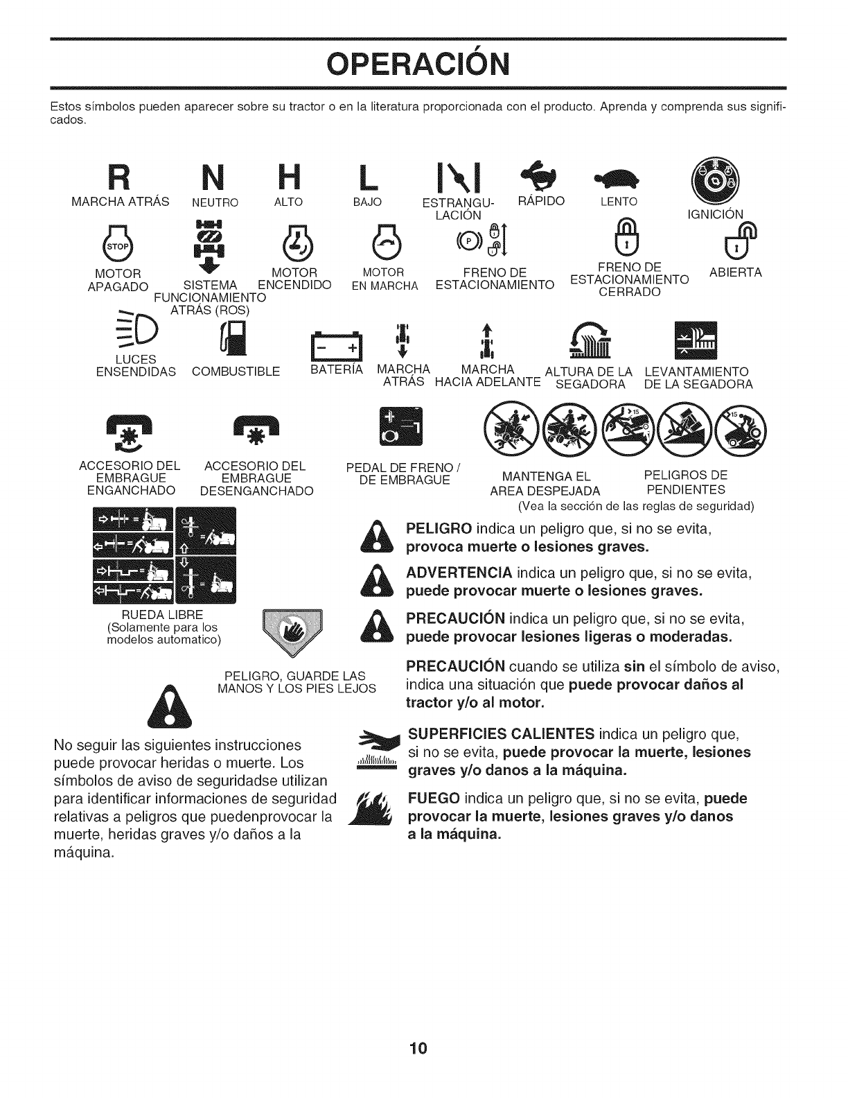
f
OPERACION
Estos simbolos pueden aparecer sobre su tractor o en la literatura proporcionada con et producto. Aprenda y comprenda sus signifi-
cados.
MARCHA ATRAS NEUTRO ALTO
6
MOTOR
APAGADO
LUCES
ENSENDIDAS COMBUSTIBLE
LENTO IGNICION
-- ®
I_ MOTOR MOTOR FRENO DE FRENO DE ABIERTA
SISTEMA ENCENDIDO EN MARCHA ESTACIONAMIENTO ESTACIONAMIENTO
FUNCIONAMIENTO CERRADO
LI",I
BAJO ESTRANGU- R_,PIDO
LACION
BATERIA MARCHA MARCHA ALTURA DE LA
ATRAS HACIA ADELANTE SEGADORA LEVANTAMIENTO
DE LA SEGADORA
ACCESORIO DEL ACCESORIO DEL
EMBRAGUE EMBRAGUE
ENGANCHADO DESENGANCHADO
RUEDA LIBRE
(Solamente para los
modelos automatico)
PELIGRO, GUARDE LAS
MANOS Y LOS PIES LEJOS
PEDAL DE FRENO/
DE EMBRAGUE
&
MANTENGA EL PEMGROS DE
AREA DESPEJADA PENDIENTES
(Vea la secci6n de las reglas de seguridad)
PELiGRO indica un peligro que, si no se evita,
provoca muerte o lesiones graves.
ADVERTENCIA indicaun peligroque, sino se evita,
puede provocar muerte o lesiones graves.
PRECAUCION indica un peligro que, si no se evita,
puede provocar lesiones ligeras o moderadas.
PRECAUCI(SN cuando se utilizasin elsimbolo de aviso,
indica una situaci6n que puede provocar da_os al
tractor y/o al motor.
No seguir las siguientes instrucciones
puede provocar heridas o muerte. Los
simbolos de aviso de seguridadse utilizan
para identificar informaciones de seguridad
relativas a peligros que puedenprovocar la
muerte, heridas graves y/o da5os a la
maquina.
SUPERFICIES CALIENTES indica un peligro que,
si no se evita, puede provocar la muerte, lesiones
graves y/o danos a la maquina.
FUEGO indica un peligro que, si no se evita, puede
provocar la muerte, lesiones graves y/o danos
ala maquina.
10
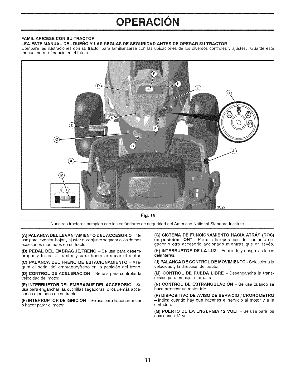
f
OPERACION
FAMILIARICESE CON SU TRACTOR
LEA ESTE MANUAL DEL DUEllO YLAS REGLAS DE SEGURIDAD ANTES DE OPERAR SU TRACTOR
Compare las ilustraciones con su tractor para familiarizarse con las ubicaciones de los diversos controles y ajustes.
manual para referencia en el futuro.
Guarde este
3027
Fig. 16
Nuestros tractores cumpten con los est&ndares de seguridad det American National Standard institute.
(A) PALANCA DEL LEVANTAMIENTO DEL ACCESORIO - Se
usa para levantar, bajar y ajustar et conjunto segador o los dem&s
accesorios montados en su tractor.
(B) PEDAL DEL EMBRAGUE/FRENO -Se usa para desem-
bragar y frenar et tractor y para hacer arrancar el motor.
(C) PALANCA DEL FRENO DE ESTACIONAMIENTO -Ase-
gura el pedal det embrague/freno en la posici6n det freno.
(D) CONTROL DE ACELERACK_N - Se usa para controlar la
vetocidad det motor.
(E) INTERRUPTOR DEL EMBRAGUE DEL ACCESORIO - Se
usa para enganchar las cuchillas segadoras, o los dem&s acce-
sorios montados en su tractor.
(F) INTERRUPTOR DE IGNICK_N - Se usa para hacer arrancar
o hacer parar et motor.
(G) SISTEMA DE FUNCIONAMIENTO HACIA ATRAS (ROS)
en posici6n "ON" -Permite la operaci6n del conjunto se-
gador o otro accesorio accionado mientras que en reves.
(H) INTERRUPTOR DE LA LUZ - Enciende y apaga las luces
detanteras.
(J) PALANCA DE CONTROL DE MOVIMIENTO - Setecciona la
vetocidad y la direcci6n det tractor.
(M) CONTROL DE RUEDA LIBRE - Desengancha la trans-
misi6n para empujar o arrastrar.
(N) CONTROL DE ESTRANGULACION -Se usa cuando se
hace arrancar un motor frio.
(P) DISPOSITIVO DE AVISO DE SERVICIO /CRONOMETRO
- Indica cu&ndo hay que hacerles et servicio al motor y a la
cortadora.
(Q) PUERTO DE LA ENGERGIA 12 VOLT - Se usa para los
accesorios 12-volt.
11
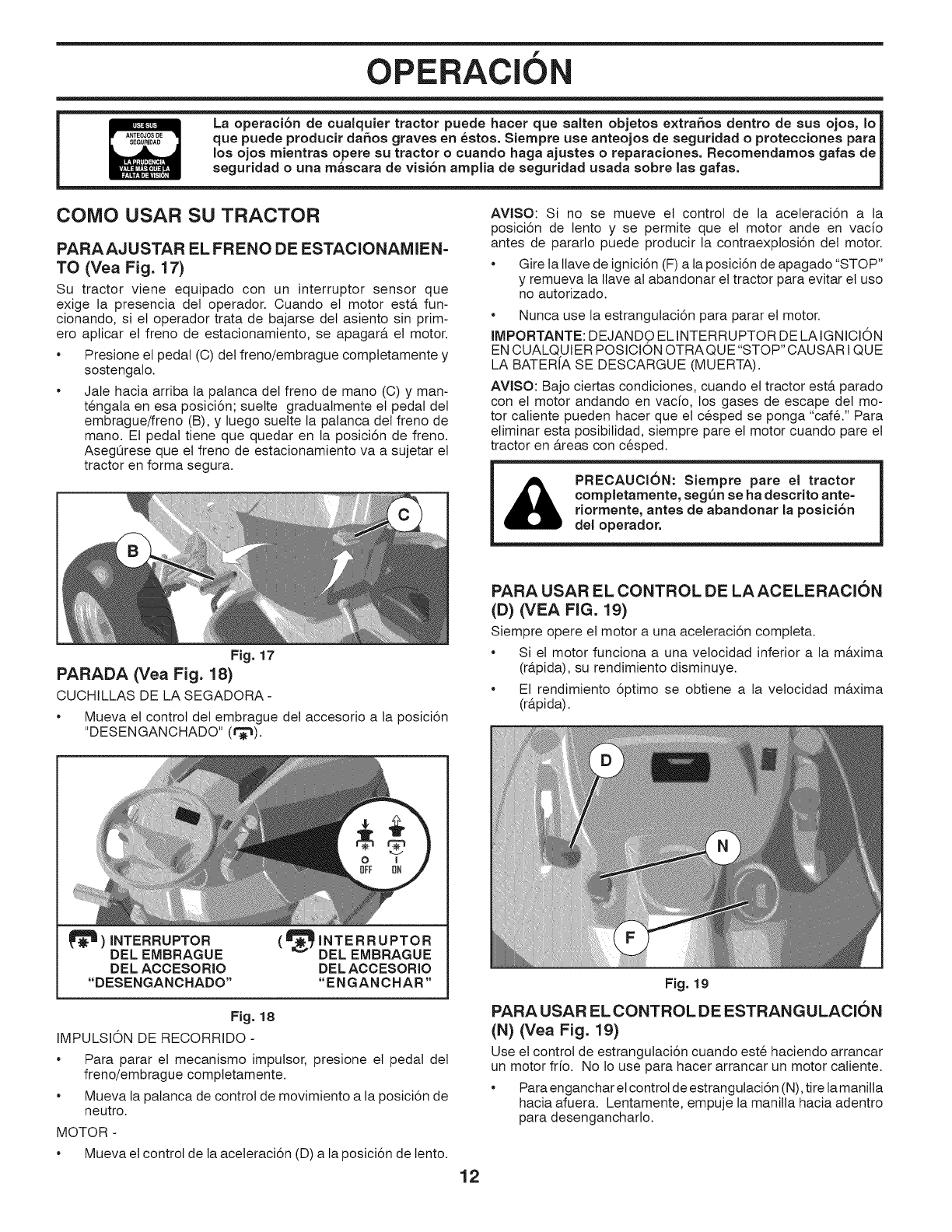
f
OPERAClON
La operaciSn de cualquier tractor puede hacer que salten objetos extraflos dentro de sus ojos, Io
que puede producir daSos graves en 6stos. Siempre use anteojos de seguridad o protecciones para
los ojos rnientras opere su tractor o cuando haga ajustes oreparaciones, Recomendarnos gafas de
seguridad ouna rn_scara de visi6n arnplia de seguridad usada sobre las gafas.
COMO USAR SU TRACTOR
PARAAJUSTAR EL FRENO DE ESTACIONAMIEN=
TO (Vea Fig. 17)
Su tractor viene equipado con un interruptor sensor que
exige la presencia del operador. Cuando el motor est& fun-
cionando, si et operador trata de bajarse det asiento sin prim-
ero aplicar el freno de estacionamiento, se apagar& et motor.
• Presione et pedal (C) det freno/embrague comptetamente y
sostengalo.
• Jale hacia arriba la palanca del freno de mano (O) y man-
tengata en esa posici6n; suelte gradualmente el pedal del
embrague/freno (B), y luego suelte la palanca del freno de
mano. Et pedal tiene que quedar en la posici6n de freno.
Asegt3rese que et freno de estacionamiento va a sujetar et
tractor en forma segura.
AVlSO: Si no se mueve et control de la aceleraci6n a la
posici6n de lento y se permite que el motor ande en vacfo
antes de pararlo puede producir la contraexplosi6n del motor.
• Gire la Ilave de ignici6n (F) a la posici6n de apagado "STOP"
y remueva la Ilave al abandonar et tractor para evitar et uso
no autorizado.
• Nunca use la estrangutaci6n para parar et motor.
IMPORTANTE: DEJANDO EL INTERRUPTOR DE LA IGNICION
EN CUALQUIER POSICION OTRA QUE "STOP" CAUSAR I QUE
LA BATERIA SE DESCARGUE (MUERTA).
AVISO: Bajo ciertas condiciones, cuando et tractor est& parade
con et motor andando en vacfo, los gases de escape det mo-
tor caliente pueden hacer que et cesped se ponga "cafe." Para
eliminar esta posibitidad, siempre pare et motor cuando pare et
tractor en &reas con cesped.
PRECAUCI6N: Siernpre pare el tractor
completarnente, seg_n se ha descrito ante=
riormente, antes de abandonar la posici6n
del operador.
Fig. 17
PARADA (Vea Fig. 18)
CUCHILLAS DE LA SEGADORA -
• Mueva et control det embrague del accesorio a la posici6n
"DESENGANCHADO" (t_"_).
PARA USAR EL CONTROL DE LAACELERACION
(D) (VEA FIG. 19)
Siempre opere et motor a una aceteraci6n completa.
• Si et motor funciona a una velocidad inferior a la m&xima
(r&pida), su rendimiento disminuye.
• El rendimiento 6ptimo se obtiene a la vetocidad m&xima
(r&pida).
)INTERRUPTOR
DEL EMBRAGUE
DEL ACCESORIO
DESENGANOHADO
(_INTERRUPTOR
_DELEMBRAGUE
DELACCESORIO
"ENGANCHAR"
Fig. 18
IMPULSION DE RECORRIDO -
• Para parar et mecanismo imputsor, presione et pedal det
freno/embrague completamente.
• Mueva la palanca de control de movimiento a la posici6n de
neutro.
MOTOR -
• Mueva et control de la aceteraci6n (D) a la posici6n de lento.
Fig. 19
PARA USAR EL CONTROL DE ESTRANGULACION
(N) (Vea Fig. 19)
Use et control de estrangutaci6n cuando este haciendo arrancar
un motor frio. No Io use para hacer arrancar un motor caliente.
• Para enganchar el control de estrangutaci6n (N), tire la manitla
hacia afuera. Lentamente, empuje la manilla hacia adentro
para desengancharlo.
12
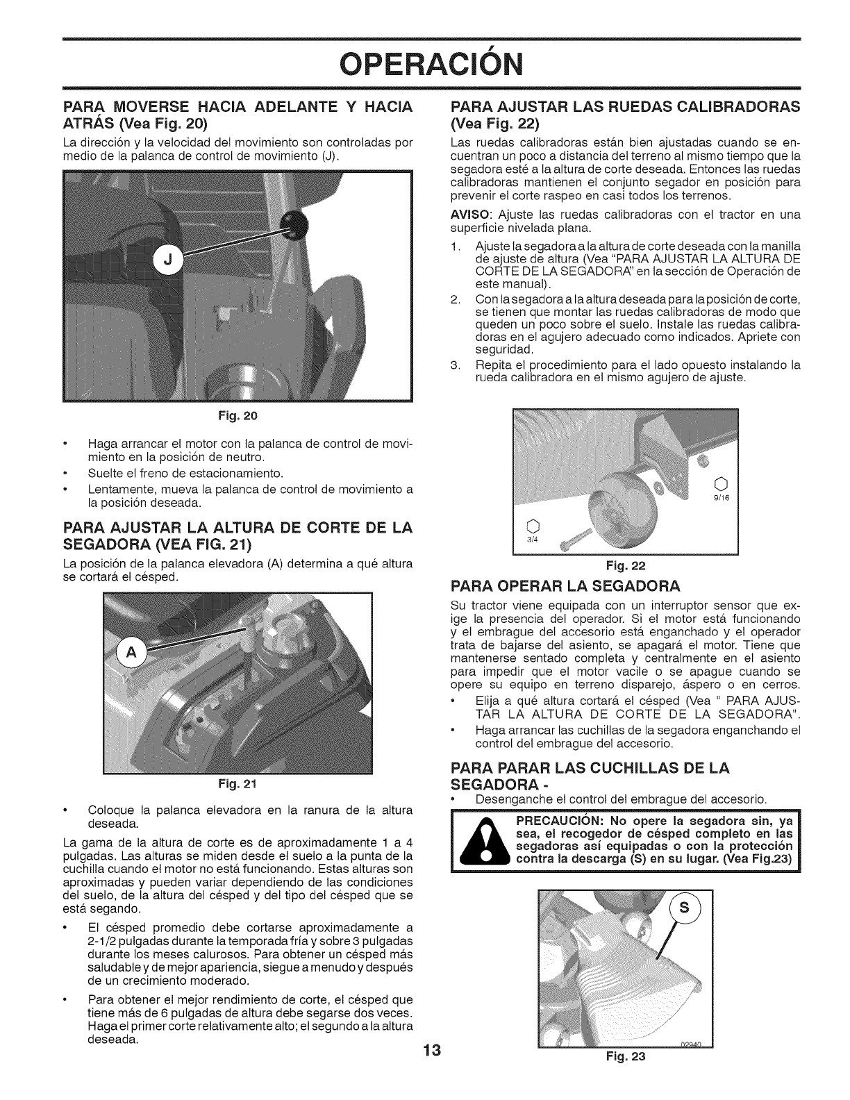
f
OPERAClON
PARA MOVERSE HACIA ADELANTE Y HACIA
ATRAS (Vea Fig. 20)
La direcci6n y la velocidad det movimiento son controladas por
medio de la palanca de control de movimiento (J).
Fig. 20
PARA AJUSTAR LAS RUEDAS CALIBRADORAS
(Vea Fig. 22)
Las ruedas calibradoras est&n bien ajustadas cuando se en-
cuentran un poco a distancia det terreno al mismo tiempo que la
segadora este a la altura de corte deseada. Entonces las ruedas
calibradoras mantienen el conjunto segador en posici6n para
prevenir et corte raspeo en casi todos los terrenos.
AVISO: Ajuste las ruedas calibradoras con et tractor en una
superficie nivetada plana.
1. Ajuste la segadora a la altura de corte deseada con ta manitla
de ajuste de altura (Vea "PARA AJUSTAR LA ALTURA DE
CORTE DE LA SEGADORAF en ta secci6n de Operaci6n de
este manual).
2. Con ta segadora a la altura deseada para la posici6n de corte,
se tienen que montar las ruedas calibradoras de modo que
queden un poco sobre el sueto. Instale las ruedas calibra-
doras en el agujero adecuado como indicados. Apriete con
seguridad.
3. Repita el procedimiento para et lado opuesto instalando la
rueda calibradora en et mismo agujero de ajuste.
•Haga arrancar et motor con la patanca de control de movi-
miento en la posici6n de neutro.
•Suelte et freno de estacionamiento.
•Lentamente, mueva la palanca de control de movimiento a
la posici6n deseada.
PARA AJUSTAR LA ALTURA DE CORTE DE LA
SEGADORA (VEA FIG. 21)
La posici6n de la palanca elevadora (A) determina a que altura
se cortar& el cesped.
Fig. 21
Coloque la patanca elevadora en la ranura de la altura
deseada.
La gama de la altura de corte es de aproximadamente 1 a 4
pulgadas. Las alturas se miden desde el suelo a la punta de la
cuchilla cuando el motor no est& funcionando. Estas alturas son
aproximadas y pueden variar dependiendo de las condiciones
del suelo, de la attura del cesped y del tipo del cesped que se
est& segando.
• El cesped promedio debe cortarse aproximadamente a
2-1/2 pulgadas durante la temporada fria y sobre 3 pulgadas
durante los meses calurosos. Para obtener un cesped m&s
saludable y de mejor apariencia, siegue a menudo y despues
de un crecimiento moderado.
Para obtener el mejor rendimiento de corte, el cesped que
tiene m&s de 6 pulgadas de altura debe segarse dos veces.
Haga el primer corte relativamente alto; el segundo a la altura
deseada.
O
3/4
Fig. 22
PARA OPERAR LA SEGADORA
Su tractor viene equipada con un interruptor sensor que ex-
ige la presencia del operador. Si el motor esta. funcionando
y et embrague det accesorio est& enganchado y et operador
trata de bajarse det asiento, se apagar& et motor. Tiene que
mantenerse sentado completa y centralmente en el asiento
para impedir que el motor vacile o se apague cuando se
opere su equipo en terreno disparejo, &spero o en cerros.
• Etija a que altura cortar& el cesped (Vea " PARA AJUS-
TAR LA ALTURA DE CORTE DE LA SEGADORA".
• Haga arrancar las cuchillas de ta segadora enganchando et
control det embrague del accesorio.
PARA PARAR LAS CUCHILLAS DE LA
SEGADORA =
Desenganche et control det embrague det accesorio.
&PRECAUCI6N: No opere la segadora sin, ya
sea, el recogedor de c6sped completo an las
segadoras asi equipadas o con la protecci6n
contra la descarga (S) en su lugar. (Vea Fig,23)
13
!0
Fig. 23
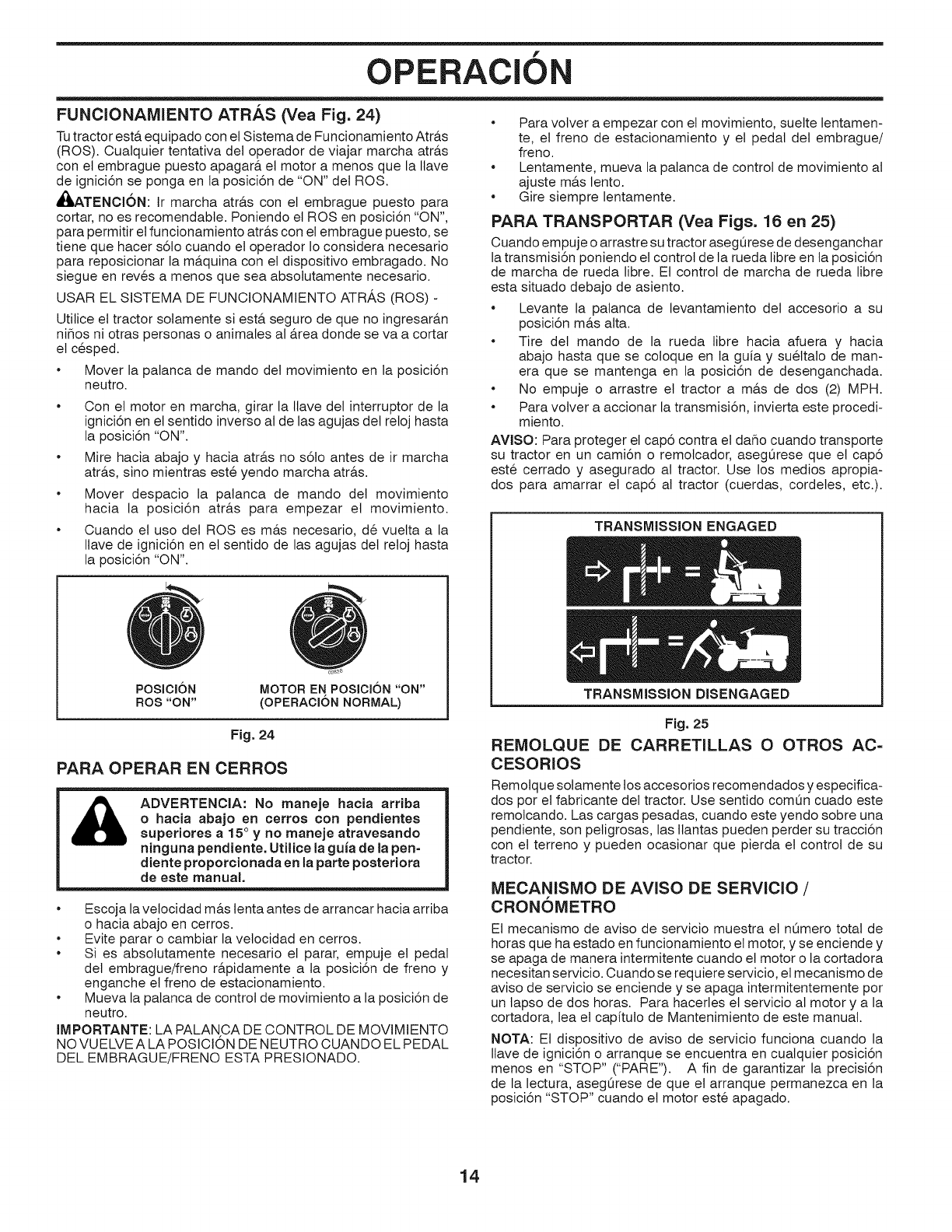
f
OPERAClON
FUNCIONAMIENTO ATRAS (Vea Fig. 24)
Tutractor est& equipado con et Sistema de Funcionamiento Atr&s
(ROS). Cualquier tentativa del operador de viajar marcha atr&s
con el embrague puesto apagar& et motor a menos que la Ilave
de ignici6n se ponga en ta posici6n de "ON" det ROS.
,_,ATENCI6N: Ir marcha atr&s con el embrague puesto para
cortar, no es recomendabte. Poniendo el ROSen posici6n "ON",
para permitir el funcionamiento atr&s con el embrague puesto, se
tiene que hacer s6to cuando el operador Io considera necesario
para reposicionar la m&quina con el dispositivo embragado. No
siegue en reves a menos que sea absolutamente necesario.
USAR EL SISTEMA DE FUNCIONAMIENTO ATRAS (ROS) -
Utilice et tractor solamente si est& seguro de que no ingresar&n
niflos ni otras personas o animales al &rea donde se va a cortar
et cesped.
Mover la palanca de mando det movimiento en la posici6n
neutro.
Con et motor en marcha, girar la Ilave del interruptor de la
ignici6n en el sentido inverso al de las agujas det retoj hasta
la posici6n "ON".
Mire hacia abajo y hacia atr&s no s61o antes de ir marcha
atr&s, sino mientras este yendo marcha atr&s.
Mover despacio la patanca de mando det movimiento
hacia la posici6n atr&s para empezar el movimiento.
Cuando el uso det ROSes m&s necesario, de vuelta a la
Ilave de ignici6n en et sentido de las agujas det retoj hasta
la posici6n "ON".
POSICION
ROS "ON"
MOTOR EN POSICI6N "ON"
(OPERACION NORMAL)
Fig. 24
PARA OPERAR EN CERROS
ADVERTENCIA: No maneje hacia arriba
o hacia abajo en cerros con pendientes
superiores a 15° y no maneje atravesando
ninguna pendiente. Utilice la guia de la pen=
diente proporcionada en la parte posteriora
de este manual.
Escoja la velocidad m&s tenta antes de arrancar hacia arriba
o hacia abajo en cerros.
Evite parar o cambiar la vetocidad en cerros.
Si es absotutamente necesario et parar, empuje et pedal
del embrague/freno r&pidamente a la posici6n de freno y
enganche el freno de estacionamiento.
Mueva la palanca de control de movimiento a la posici6n de
neutro.
IMPORTANTE: LA PALANCA DE CONTROL DE MOVIMIENTO
NO VUELVE A LA POSICION DE NEUTRO CUANDO EL PEDAL
DEL EMBRAGUE/FRENO ESTA PRESIONADO.
Para votver a empezar con et movimiento, suelte lentamen-
te, el freno de estacionamiento y et pedal det embrague/
freno.
Lentamente, mueva la palanca de control de movimiento al
ajuste m&s lento.
Gire siempre lentamente.
PARA TRANSPORTAR (Vea Figs. 16 en 25)
Cuando empuje o arrastre su tractor asegQrese de desenganchar
la transmisi6n poniendo et control de la rueda libre en la posici6n
de marcha de rueda libre. El control de marcha de rueda libre
esta situado debajo de asiento.
Levante la patanca de levantamiento det accesorio a su
posici6n m&s alta.
Tire det mando de la rueda tibre hacia afuera y hacia
abajo hasta que se coloque en ta guia y suettalo de man-
era que se mantenga en la posici6n de desenganchada.
No empuje o arrastre et tractor a m&s de dos (2) MPH.
Para votver a accionar la transmisi6n, invierta este procedi-
miento.
AVISO: Para proteger el cap6 contra el daflo cuando transporte
su tractor en un cami6n o remolcador, asegOrese que et cap6
este cerrado y asegurado al tractor. Use los medics apropia-
dos para amarrar et cap6 al tractor (cuerdas, cordetes, etc.).
TRANSMiSSiON ENGAGED
TRANSMiSSiON DISENGAGED
Fig. 25
REMOLQUE DE CARRETILLAS O OTROS AC=
CESORIOS
Remolque solamente los accesorios recomendados y especifica-
dos por el fabricante del tractor. Use sentido comOn cuado este
remolcando. Las cargas pesadas, cuando este yendo sobre una
pendiente, son petigrosas, las llantas pueden perder su tracci6n
con et terreno y pueden ocasionar que pierda et control de su
tractor.
MECANISIVIO DE AVISO DE SERVIClO /
CRONOMETRO
El mecanismo de aviso de servicio muestra et nOmero total de
horas que ha estado en funcionamiento el motor, y se enciende y
se apaga de manera intermitente cuando el motor o la cortadora
necesitan servicio. Cuando se requiere servicio, el mecanismo de
aviso de servicio se enciende y se apaga intermitentemente por
un tapso de dos horas. Para hacerles el servicio al motor y a la
cortadora, lea et capituto de Mantenimiento de este manual.
NOTA: El dispositivo de aviso de servicio funciona cuando la
Ilave de ignici6n o arranque se encuentra en cualquier posici6n
menos en "STOP" ("PARE"). A fin de garantizar la precisi6n
de la lectura, asegQrese de que el arranque permanezca en la
posici6n "STOP" cuando et motor este apagado.
14
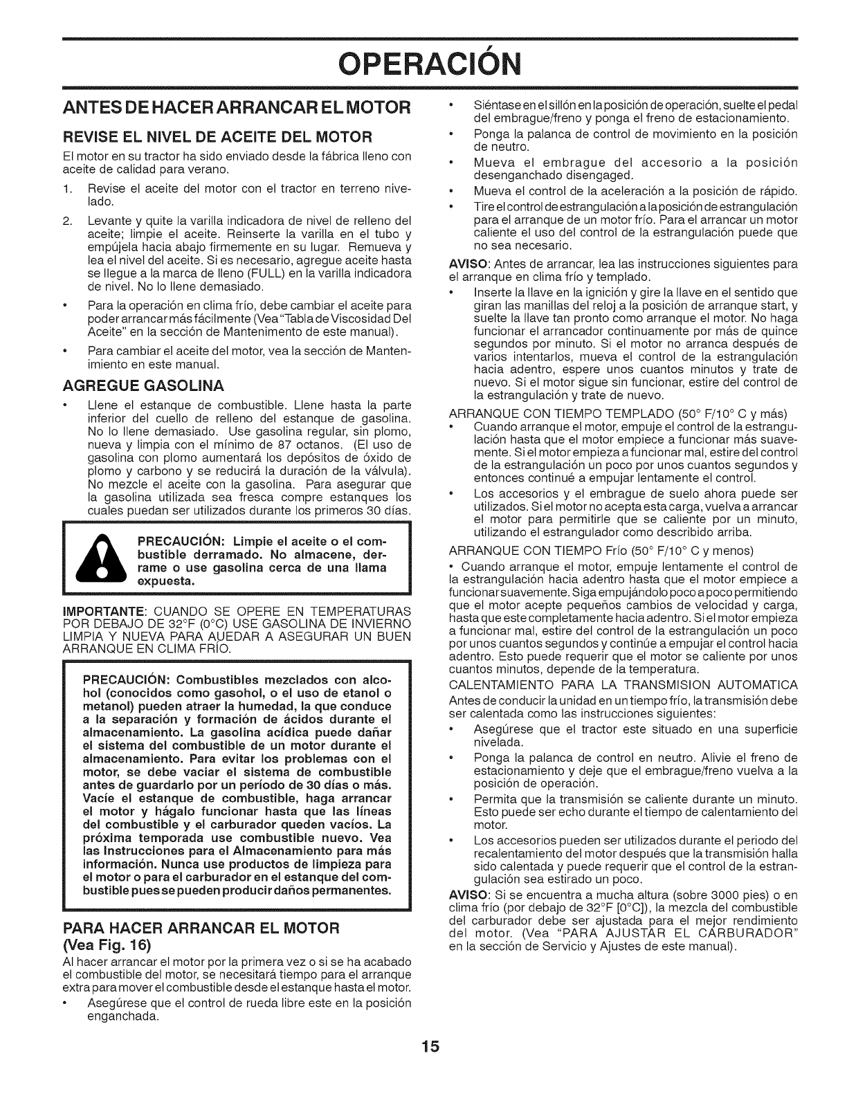
f
OPERAClON
ANTES DE HACER ARRANCAR EL MOTOR
REVISE EL NIVEL DE ACEITE DEL MOTOR
El motor en su tractor ha sido enviado desde la f&brica Ileno con
aceite de calidad para verano.
1. Revise et aceite det motor con et tractor en terreno nive-
lado.
2, Levante y quite la varilla indicadora de nivet de retleno det
aceite; limpie et aceite. Reinserte la varilla en et tubo y
empt3jeta hacia abajo firmemente en su tugar. Remueva y
lea el nivel det aceite. Si es necesario, agregue aceite hasta
se tlegue a la marca de lleno (FULL) en la varilla indicadora
de nivel. No Io Ilene demasiado.
Para la operaci6n en clima frio, debe cambiar et aceite para
poder arrancar m&s f&cilmente (Vea"Tabta de Viscosidad Det
Aceite" en la secci6n de Mantenimento de este manual).
Para cambiar et aceite det motor, vea la secci6n de Manten-
imiento en este manual.
AGREGUE GASOLINA
Llene et estanque de combustible. Llene hasta la parte
inferior del cuelto de retleno del estanque de gasotina.
No 1o Ilene demasiado. Use gasolina regular, sin plomo,
nueva y limpia con et minimo de 87 octanos. (El uso de
gasotina con plomo aumentar& los dep6sitos de 6xido de
ptomo y carbono y se reducir& ta duraci6n de la v&tvuta).
No mezcte el aceite con la gasolina. Para asegurar que
la gasolina utilizada sea fresca compre estanques los
cuales puedan ser utilizados durante los primeros 30 dfas.
PRECAUCI6N: Lirnpie el aceite o el corn-
bustible derrarnado. No alrnacene, der=
rarne o use gasolina cerca de una llama
expuesta.
IMPORTANTE: CUANDO SE OPERE EN TEMPERATURAS
POR DEBAJO DE 32°F (0°C) USE GASOLINA DE INVIERNO
LIMPIA Y NUEVA PARA AUEDAR A ASEGURAR UN BUEN
ARRANQUE EN CLIMA FRIO.
PRECAUCI6N: Combustibles rnezclados con alto=
hol (conocidos corno gasohol, o el uso de etanol o
rnetanol) pueden atraer la hurnedad, la que conduce
a la separaci6n y forrnaci6n de _cidos durante el
alrnacenarniento, La gasolina acidica puede daSar
el sisterna del combustible de un motor durante el
alrnacenarniento. Para evitar los problernas con el
motor, se debe vaciar el sisterna de combustible
antes de guardarlo pot un periodo de 30 dias o rn_s.
Vacie el estanque de combustible, haga arrancar
el motor y h_galo funcionar hasta que las lineas
del combustible y el carburador queden vacios. La
pr6xirna ternporada use combustible nuevo. Vea
las Instrucciones para el Alrnacenarniento para rn_s
inforrnaci6n. Nunca use productos de lirnpieza para
el motor o para el carburador en el estanque del corn-
bustible pues se pueden producir da_os perrnanentes,
PARA HACER ARRANCAR EL MOTOR
(Vea Fig. 16)
AI hacer arrancar et motor por la primera vez o si se ha acabado
el combustible del motor, se necesitar& tiempo para et arranque
extra para mover et combustible desde el estanque hasta el motor.
AsegOrese que et control de rueda libre este en la posici6n
enganchada.
* Sientase en el sill6n en la posici6n de operaci6n, suelte et pedal
det embrague/freno y ponga et freno de estacionamiento.
* Ponga la palanca de control de movimiento en la posici6n
de neutro.
* Mueva et embrague del accesorio a la posici6n
desenganchado disengaged.
* Mueva el control de la aceteraci6n a la posici6n de r&pido.
* Tire et control de estrangulaci6n a laposici6n de estrangulaci6n
para el arranque de un motor frio. Para el arrancar un motor
caliente el uso det control de la estrangutaci6n puede que
no sea necesario.
AVISO: Antes de arrancar, lea las instrucciones siguientes para
et arranque en ctima frio y templado.
Inserte la Ilave en ta ignici6n y gire la llave en et sentido que
giran las manillas del retoj a la posici6n de arranque start, y
suette la ttave tan pronto como arranque el motor. No haga
funcionar et arrancador continuamente por m&s de quince
seg.undos por minuto. Si et motor no arranca despues de
vanos intentarlos, mueva el control de la estrangutaci6n
hacia adentro, espere unos cuantos minutos y trate de
nuevo. Si et motor sigue sin funcionar, estire det control de
la estrangutaci6n y trate de nuevo.
ARRANQUE CON TIEMPO TEMPLADO (50° F/10 ° C y m&s)
* Cuando arranque et motor, empuje el control de la estrangu-
laci6n hasta que et motor empiece a funcionar m&s suave-
mente. Si et motor empieza a funcionar mal, estire del control
de ta estrangulaci6n un poco por unos cuantos segundos y
entonces continue a empujar lentamente et control.
* Los accesorios y et embrague de suelo ahora puede ser
utilizados. Si et motor no acepta esta carga, vuetva a arrancar
et motor para permitirle que se caliente por un minuto,
utilizando et estrangutador como describido arriba.
ARRANQUE CON TIEMPO Frio (50° F/10 ° C y menos)
* Cuando arranque et motor, empuje tentamente et control de
la estrangutaci6n hacia adentro hasta que el motor empiece a
funcionar suavemente. Siga empuj&ndolo poco a poco permitiendo
que el motor acepte pequeflos cambios de velocidad y carga,
hasta que este comptetamente hacia adentro. Si etmotor empieza
a funcionar mal, estire det control de la estrangutaci6n un poco
por unos cuantos segundos y continQe a empujar el control hacia
adentro. Esto puede requerir que et motor se caliente pot unos
cuantos minutos, depende de la temperatura.
CALENTAMIENTO PARA LA TRANSMISION AUTOMATICA
Antes de conducir ta unidad en untiempo frio, la transmisi6n debe
ser calentada como las instrucciones siguientes:
* AsegQrese que et tractor este situado en una superficie
nivelada.
* Ponga la palanca de control en neutro. Ativie et freno de
estacionamiento y deje que et embrague/freno vuetva a la
posici6n de operaci6n.
* Permita que la transmisi6n se caliente durante un minuto.
Esto puede ser echo durante et tiempo de calentamiento det
motor.
* Los accesorios pueden ser utitizados durante et periodo det
recalentamiento del motor despues que la transmisi6n halla
sido catentada y puede requerir que et control de la estran-
gutaci6n sea estirado un poco.
AVISO: Si se encuentra a mucha altura (sobre 3000 pies) o en
clima frio (por debajo de 32°F [0°C]), la mezcla del combustible
del carburador debe ser ajustada para et mejor rendimiento
del motor. (Vea "PARA AJUSTAR EL CARBURADOR"
en la secci6n de Servicio y Ajustes de este manual).
15
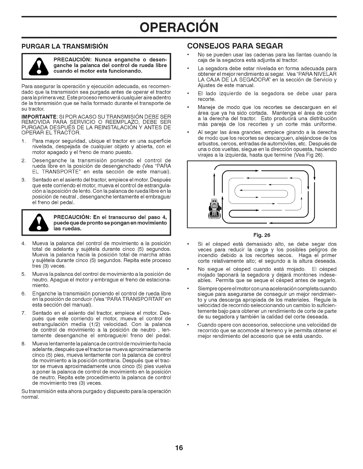
f
OPERAClON
PURGAR LA TRANSMISION CONSEJOS PARA SEGAR
PRECAUCK_)N: Nunca enganche odesen-
ganche la paJanca del control de rueda libra
cuando el motor esta funcionando,
Para asegurar la operaci6n y ejecuci6n adecuada, es recomen-
dado que la transmisi6n sea purgada antes de operar et tractor
para la primeravez. Este proceso remover& cualquier aire adentro
de la transmisi6n que se halla formado durante et transporte de
su tractor.
IMPORTANTE: SI POR ACASO SU TRANSMISION DEBE SER
REMOVIDA PARA SERVICIO O REEMPLAZO, DEBE SER
PURGADA DESPUES DE LA REINSTALACION Y ANTES DE
OPERAR EL TRACTOR.
1. Para mayor seguridad, ubique el tractor en una superficie
nivetada, despejada de cualquier objeto y abierta, con et
motor apagado y et freno de mano puesto.
2. Desenganche la transmisi6n poniendo et control de
rueda libre en la posici6n de desenganchado (Vea "PARA
EL TRANSPORTE" en esta secci6n de este manual).
3. Sentado en et asiento del tractor, empiece et motor. Despues
que este corriendo el motor, mueva et control de estrangula-
ci6n a la posici6n de lento. Con la patanca de rueda libre en la
posici6n de neutral, desenganche lentamente et embrague/
et freno det pedal.
PRECAUCION: En el transcurso del paso 4,
puede que de pronto se pongan en movimiento
las ruedas,
4. Mueva la palanca det control de movimiento a la posici6n
total de adelante y sujeteta durante cinco (5) segundos.
Mueva la palanca hacia la posici6n total de marcha atr&s
y sujetela durante cinco (5) segundos. Repita este proceso
tres (3) veces.
5. Mueva la palanca del control de movimiento a la posici6n de
neutro. Apague et motor y embrague el freno de estaciona-
miento.
6. Enganche la transmisi6n poniendo el control de rueda libre
en ta posici6n de conducir (Vea "PARA TRANSPORTAR" en
esta secci6n det manual).
7.
8.
Sentado en et asiento del tractor, empiece et motor. Des-
pues que este corriendo el motor, mueva el control de
estrangutaci6n media (1/2) velocidad. Con ta palanca
de control de movimiento a la posici6n de neutro , len-
tamente desenganche et embrague/et freno del pedal.
Mueva lentamente la palanca de control de movimiento hacia
adelante, despues que et tractor se mueva aproximadamente
cinco (5) pies, mueva lentamente con la palanca de control
de movimiento a la posici6n contraria. Despues que el trac-
tor se mueva aproximadamente unos cinco (5) pies vuelva
a poner la palanca de control de movimiento en ta posici6n
de neutro. Repita este procedimiento la palanca de control
de movimiento tres (3) veces.
Su transmisi6n esta ahora purgado y dispuesto para la operaci6n
normal.
No se pueden usar las cadenas para las Ilantas cuando la
caja de la segadora est& adjunta al tractor.
La segadora debe estar nivelada en forma adecuada para
obtener et mejor rendimiento al segar. Vea "PARA NIVELAR
LA CAJA DE LA SEGADORA:' en la secci6n de Servicio y
Ajustes de este manual.
Et lado izquierdo de la segadora se debe usar para
recorte.
Maneje de modo que los recortes se descarguen en el
&rea que ya ha sido cortada. Mantenga et &rea de corte
a la derecha del tractor. Esto producir& una distribuci6n
m&s pareja de los recortes y un corte m&s uniforme.
AI segar las &rea grandes, empiece girando a la derecha
de modo que los recortes se descarguen, alej&ndose de los
arbustos, cercos, entradas de autom6viles, etc. Despues de
una o dos vuettas, siegue en la direcci6n opuesta, haciendo
virajes a la izquierda, hasta que termine (Vea Fig 26).
f
Fig. 26
Si et cesped est& demasiado alto, se debe segar dos
veces para reducir la carga y los posibtes peligros de
incendio debido a los recortes secos. Haga et primer
corte retativamente alto; el segundo a la altura deseada.
No siegue el cesped cuando est& mojado. El cesped
mojado taponar& la segadora y dejar& montones indese-
ables. Permita que se seque el cesped antes de segarlo.
Siempre opere el motor con una aceleraci6n compteta cuando
siegue para asegurarse de conseguir un mejor rendimien-
to y una descarga apropiada de los materiales. Regule la
vetocidad de recorrido seleccionando un cambio 1osuficien-
temente bajo para obtener un rendimiento de corte de parte
de su segadora y tambien ta calidad det corte deseada.
Cuando opere con accesorios, seteccione una vetocidad de
recorrido que se acomode al terreno y le permita obtener et
mejor rendimiento det accesorio que se est& usando.
16
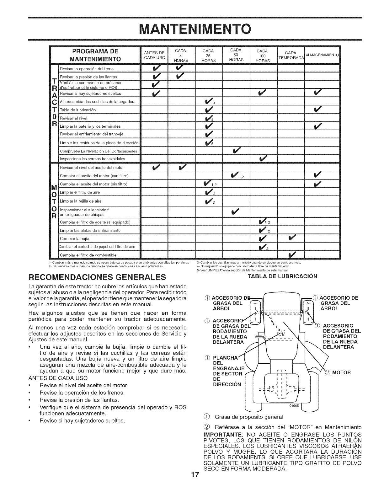
MANTENIMENTO
PROGRAMA DE CADA CADA CADA CADA
8 25 50 100
MANTENIMIENTO HORAS HORAS HORAS HORAS
Revisar la operaci6n del freno 1/
' Revisar la presi6n de las Ilantas 1/ 1/
TVerifiez la commande de presence 1/
a d'operateur et le sistema d ROS
ARevisar si hay sujetadores sueltos if If
C Afilar/cambiar las cuchillas de la segadora _lf 3
TTabla de lubricaci6n _lf
0 Revisar el nivel _4
a Limpiar la bateria y los terminales 1/
Revisar el enfriamiento del transeje _'
Limpie los residuos de la placa de direcci6n _5
Compruebe La Nivelaci6n Del Cortac_spedes 1/
Inspeccione las correas trapezoidales 1/
Revisar el nivel del aceite del motor _ 1/
Cambiar el aceite del motor (con filtro) 1/1,2
Cambiar el aceite del motor (sin filtro) 1/1,2
Limpiar el filtro de aire 1/2
TLimpiar la rejilla de aire _ilt_ 2
O Inspeccionar el silenciador/ 1/
R amortiguador de chispas
Cambiar el filtro de aceite (si equipado)
Limpiar las aletas de enfriamiento
Cambiar la bujia
2,ambiar el cartucho de papel del filtro de aire
Cambiar el filtro de combustible
1=Cambiar m_,s a menudo cuando se opere bajo carga pesada o en ambientes con altas temperaturas
2- Dar servicio mas a menudo cuando se opere en condiciones sucias o polvorosas.
RECOMENDACIONES GENERALES
ANTES DE CADA ALMACENAMIENTO
CADAUSO TEMPORADA
1/
1/
1/
1/
!/
I/2
1/ I/
!/2
3=Cambiar las cuchillas mas a menudo cuando se siegue en suelo arenoso.
4 = No requerido si equipado con una bateria libre de mantenimiento.
5= Vea "LIMPIEZA" en la secci6n de Mantenimento de este manual.
TABLA DE LUBRICACION
La garantia de este tractor no cubre los articutos que han estado
sujetos al abuso o a la negligencia del operador. Para recibir todo
el valor de ta garanfia, el operador tiene que mantener lasegadora
segQn las instrucciones descritas en este manual.
Hay algunos ajustes que se tienen que hacer en forma
peri6dica para poder mantener su tractor adecuadamente.
AI menos una vez cada estaci6n comprobar si es necesario
efectuar los adjustes descritos en las secciones de Servicio y
Ajustes de este manual.
•Una vez al aflo, cambie la bujia, limpie o cambie el ill-
tro de aire y revise si las cuchitlas y las correas esta.n
desgastadas. Una buj[a nueva y un filtro de aire limpio
aseguran una mezcla de aire-combustible adecuada y le
ayudan a que su motor funcione mejor y que dure m&s.
ANTES DE CADA USO
•Revise el nivel del aceite del motor.
•Revise la operaci6n de los frenos.
•Revise la presi6n de las Ilantas.
•Verifique que el sistema de presencia det operado y ROS
funcionen adecuatamente.
•Revise si hay sujetadores suettos.
ACCESORIO _ ACCESORIO DE
GRASA DEL GRASA DEL
ARBOL ARBOL
DE GRASA DEI ACCESORIO
RODAMIENTO DE GRASA DEL
DE LA RUEDA RODAMIENTO
DELANTERA DE LA RUEDA
DELANTERA
DEL
ENGRANAJE
DE SECTOR
DE
DIRECCION
MOTOR
17
01965
(_) Grasa de proposito general
(_) Refierase a la secci6n det "MOTOR" en Mantenimiento
IMPORTANTE: NO ACEITE O ENGRASE LOS PUNTOS
PIVOTES, LOS QUE TIENEN RODAMIENTOS DE NILON
ESPECIALES. LOS LUBRICANTES VISCOSOS ATRAERAN
POLVO Y MUGRE, LO QUE ACORTARA LA DURACION
DE LOS RODAMIENTS. SI CREE QUE LUBRICARSE, USE
SOLAMENTE UN LUBRICANTE TIPO GRAFITO DE POLVO
SECO EN FORMA MODERADA.
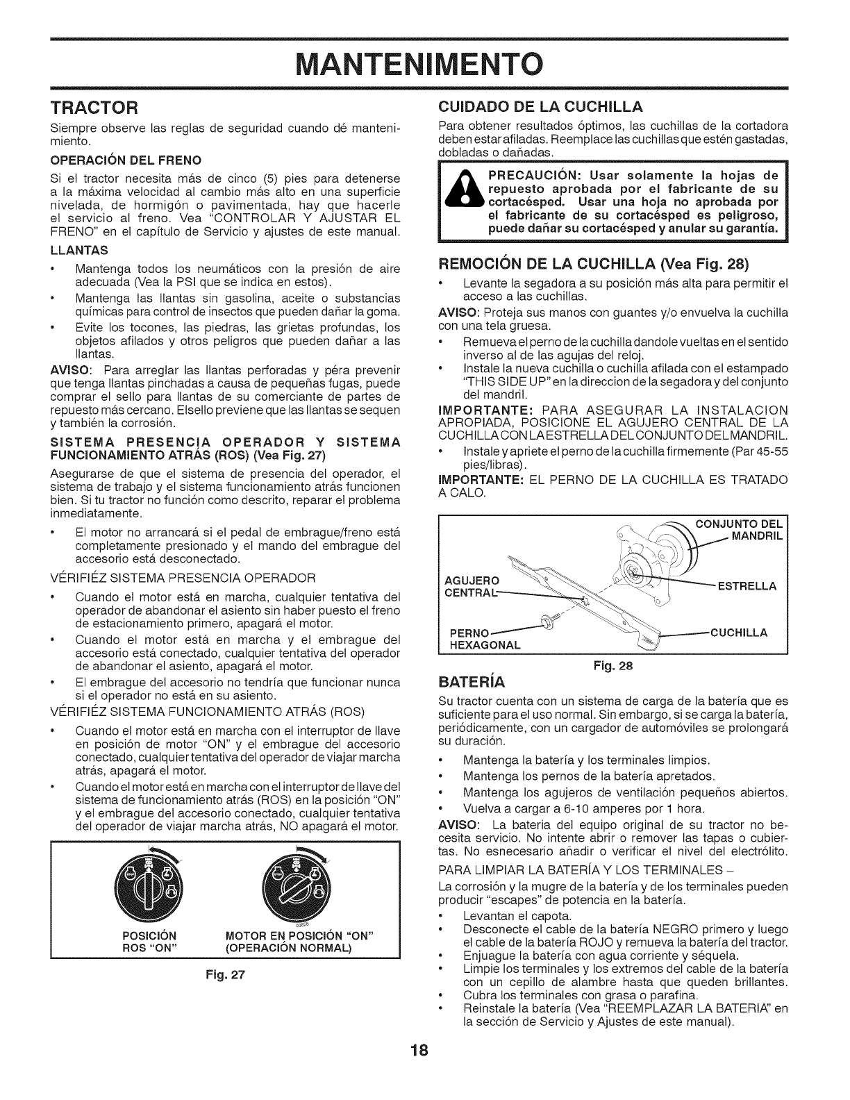
MANTENIMENTO
TRACTOR
Siempre observe las regtas de seguridad cuando de manteni-
miento.
OPERACI6N DEL FRENO
Si et tractor necesita m&s de cinco (5) pies para detenerse
a la m&xima vetocidad al cambio m&s alto en una superficie
nivetada, de hormig6n o pavimentada, hay que hacerle
el servicio al freno. Vea "CONTROLAR Y AJUSTAR EL
FRENO" en et capituto de Servicio y ajustes de este manual.
LLANTAS
Mantenga todos los neum&ticos con la presi6n de aire
adecuada (Vea la PSI que se indica en estos).
* Mantenga las Ilantas sin gasolina, aceite o substancias
quimicas para control de insectos que pueden daflar la goma.
Evite los tocones, las piedras, las grietas profundas, los
objetos afilados y otros petigros que pueden daflar alas
Ilantas.
AVISO: Para arreglar las Ilantas perforadas y p@a prevenir
que tenga Itantas pinchadas a causa de pequeflas fugas, puede
comprar el setto para Ilantas de su comerciante de partes de
repuesto m&s cercano. Etsetlo previene que las Ilantas se sequen
y tambien la corrosi6n.
SJSTEMA PRESENCJA OPERADOR Y SJSTEIVIA
FUNCIONAMIENTO ATRAS (ROS) (Vea Fig. 27)
Asegurarse de que el sistema de presencia det operador, el
sistema de trabajo y et sistema funcionamiento atr&s funcionen
bien. Si tu tractor no funci6n como descrito, reparar et probtema
inmediatamente.
El motor no arrancar& si el pedal de embrague/freno esta
comptetamente presionado y et mando det embrague det
accesorio est& desconectado.
VE_RIFIE_ZSISTEMA PRESENCIA OPERADOR
Cuando et motor est& en marcha, cualquier tentativa del
operador de abandonar et asiento sin haber puesto et freno
de estacionamiento primero, apagar& et motor.
Cuando et motor est& en marcha y et embrague del
accesorio est& conectado, cualquier tentativa del operador
de abandonar et asiento, apagar& el motor.
El embrague del accesorio no tendria que funcionar nunca
si el operador no est& en su asiento.
VE_RIFIEZ SISTEMA FUNCIONAMIENTO ATRAS (ROS)
Cuando el motor est& en marcha con et interruptor de Itave
en posici6n de motor "ON" y el embrague del accesorio
conectado, cualquier tentativa det operador de viajar marcha
atr&s, apagar& et motor.
Cuando et motor est& en marcha con el interruptor de ltave det
sistema de funcionamiento atr&s (ROS) en ta posici6n "ON"
y el embrague del accesorio conectado, cuatquier tentativa
det operador de viajar marcha atr&s, NO apagar& et motor.
POSICI6N
ROS "ON" MOTOR EN POSI¢I6N "ON"
(OPERAOION NORMAL)
Fig. 27
CUIDADO DE LA CUCHILLA
Para obtener resuttados 6ptimos, las cuchitlas de la cortadora
deben estar afiladas. Reemptace las cuchillas que esten gastadas,
dobtadas o dafladas.
PRECAUCI6N: Usar aolamente la hojaa de
repuesto aprobada pot el fabricante de au
cortac6sped. Uaar una hoja no aprobada pot
el fabricante de su cortac_aped as peligroso,
puede dahar su cortac6sped y anular su garantJa.
REIVlOCI()N DE LA CUCHILLA (Vea Fig. 28)
•Levante la segadora a su posici6n m&s alta para permitir et
acceso alas cuchitlas.
AVlSO: Proteja sus manos con guantes y/o envuetva la cuchilla
con una teta gruesa.
Remueva et perno de la cuchitta dandole vueltas en el sentido
inverso at de las agujas det reloj.
Instale la nueva cuchitta o cuchilla afilada con et estampado
"THIS SIDE UP" en la direccion de la segadora y del conjunto
del mandril.
JMPORTANTE: PARA ASEGURAR LA INSTALACION
APROPIADA, POSICIONE EL AGUJERO CENTRAL DE LA
CUCHILLACON LAESTRELLA DELCONJUNTO DELMANDRIL
•Instale yapriete et perno de la cuchitla firmemente (Par 45-55
pies/libras).
JMPORTANTE: EL PERNO DE LA CUCHILLA ES TRATADO
A CALO.
CONJUNTO DEL
MANDRIL
AGUJERO ESTRELLA
/
/
PERNO__"
HEXAGONAL
Fig. 28
BATERJA
Su tractor cuenta con un sistema de carga de la bateria que es
suficiente para el uso normal. Sin embargo, si se carga la bateria,
peri6dicamente, con un cargador de autom6viles se prolongar&
su duraci6n.
Mantenga la bateria y los terminales limpios.
Mantenga los pernos de la bateria apretados.
Mantenga los agujeros de ventilaci6n pequeflos abiertos.
Vuelva a cargar a 6-10 amperes por 1 hora.
AWSO: La bateria del equipo original de su tractor no be-
cesita servicio. No intente abrir o remover las tapas o cubier-
tas. No esnecesario afladir o verificar et nivet det etectr6tito.
PARA LIMPIAR LA BATER[A Y LOS TERMINALES -
La corrosi6n y la mugre de la bateria y de los terminales pueden
producir "escapes" de potencia en la bateria.
Levantan el capota.
Desconecte et cable de la bateria NEGRO primero y luego
el cable de la bateria ROJO y remueva la bateria det tractor.
Enjuague la baterfa con agua corriente y sequela.
Limpie los terminales y los extremos del cable de la bateria
con un cepillo de alambre hasta que queden brillantes.
Cubra los terminales con grasa o parafina.
Reinstale la bateria (Vea "REEMPLAZAR LA BATERIAF en
la secci6n de Servicio y Ajustes de este manual).
18
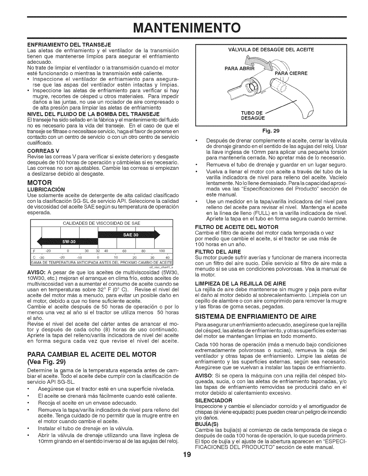
MANTENIMENTO
ENFRIAMIENTO DEL TRANSEJE
Las aletas de enfriamiento y et ventilador de la transmisi6n
tienen que mantenerse limpios para asegurar et enfriamiento
adecuado.
No trate de limpiar et ventilador o la transmisi6n cuando el motor
este funcionando o mientras la transmisi6n este caliente.
Inspeccione et ventilador de enfriamiento para asegura-
rse que las aspas del ventilador esten intactas y limpias.
Inspeccione las aletas de enfriamiento para verificar si hay
mugre, recortes de cesped u otros materiales. Para impedir
daflos alas juntas, no use un rociador de aire compresado o
de alta presi6n para limpiar las aletas de enfriamiento
NIVEL DEL FLUIDO DE LA BOMBA DEL TRANSEJE
El transeje ha sido setlado en la fAbrica y el mantenimiento detfluido
no es necesario para la vida del transeje. En et caso de que el
transeje se filtrase o necesitase servicio, haga et favor de ponerse en
contacto con un centro de servicio o con un otro centro de servicio
cualificado.
CORREAS V
Revise las correas V para verificar si existe deterioro y desgaste
despues de 100 horas de operaci6n y c&mbielas si es necesario.
Las correas no son ajustabtes. Cambie las correas si empiezan
a destizarse debido al desgaste.
MOTOR
LUBRICACI6N
Use solamente aceite de detergente de alta calidad clasificado
con la ctasificaci6n SG-SL de servicio API. Seleccione la calidad
de viscosidad del aceite SAE segOn su temperatura de operaci6n
esperada.
CALIDADES DE VlSCOSlDAD DE SAE
F -20 0 30 32 40 60 80 100
c -d0 -20 -10 _ ;0 _0 do 4o
GAMA DE TEMPERATURA ANTICIPADA ANTES DEL PROXIMO CAMBIO DE ACEITE
oil viscchartl
AVISO: A pesar de que los aceites de muttiviscosidad (5W30,
10W30, etc.) mejoran el arranque en ctima fr[o, estos aceites de
multiviscosidad van a aumentar et consumo de aceite cuando se
usan en temperaturas sobre 32° F (0° C). Revise et nivet det
aceite del motor m&s a menudo, para evitar un posibte daflo en
et motor, debido a que no tiene suficiente aceite.
Cambie et aceite despues de 50 horas de operaci6n o por Io
menos una vez al aflo si et tractor se utiliza menos 50 horas
et aflo.
Revise el nivel del aceite del c&rter antes de arrancar et mo-
tor y despues de cada ocho (8) horas de uso continuado.
Apriete la tapa det relleno/varilla indicadora de nivet det aceite
en forma segura cada vez que revise et nivel det aceite.
PARA CAMBIAR EL ACEITE DEL MOTOR
(Vea Fig. 29)
Determine la gama de la temperatura esperada antes de cam-
biar et aceite. Todo et aceite debe cumptir con la clasificaci6n de
servicio API SG-SL.
• AsegOrese que el tractor este en una superficie nivelada.
• Et aceite se drenar& m&s f&cilmente cuando este catiente.
• Recoja et aceite en un envase adecuado.
• Remueva la tapa/varilla indicadora de nivel para relleno del
aceite. Tenga cuidado de no permitir que la mugre entre en
el motor cuando cambie el aceite.
• Instalar et tubo de drenaje en la v&tvuta.
• Abrir la v&lvula de drenaje utitizando una Ilave inglesa de
10mm girando en et sentido inverso al de las agujas det reloj.
V/_LVULA DE DESAGUE DEL ACEITE
PARA ABRIR PARA ClERRE
19
TUBO DE
DESAGUE
Fig. 29
• Despues de drenar complemente el aceite, cerrar la v&lvuta
de drenaje girando en el sentido de las agujas del reloj. Usar
la Ilave inglesa de 10mm para aplicar una pequefla torsi6n
para mantenerla cerrada. No apretar m&s de 1onecesario.
• Remueva et tubo de drenaje y guardar en un lugar seguro.
• Vuetva a tlenar et motor con aceite a traves det tubo de la
varilla indicadora de nivel para retteno del aceite. Vacfelo
lentamente. No lo tlene demasiado. Para la capacidad aproxi-
mada vea las "Especificaciones det Producto" secci6n de
este manual.
• Use un medidor en la tapa/varilla indicadora del nivel para
relleno det aceite para revisar et nivet. Mantenga et aceite
en ta linea de tleno (FULL) en la varilla indicadora de nivel.
Apriete la tapa en et tubo en forma segura cuando termine.
FILTRO DE ACEITE DEL MOTOR
Cambie et filtro de aceite det motor cada temporada ovez
por medio que cambie et aceite, si et tractor se usa m&s de
100 horas en un aflo.
FILTRO DEL AIRE
Su motor puede sufrir averfas y funcionar de manera incorrecta
con un filtro det aire sucio. Dete servicio al filtro de aire m&s a
menudo si se usa en condiciones polvorosas. Vea la manual de
la motor.
LIMPIEZA DE LA REJILLA DE AIRE
La rejilla de aire debe mantenerse sin mugre y paja para evitar
et daflo al motor debido al sobrecatentamiento. Limpiela con un
cepillo de alambre o con aire comprimido para remover la mugre
y las fibras de goma secas, pegadas.
SISTEMA DE ENFRIAMIENTO DE AIRE
Para asegurar un enfriamiento adecuado, asegQrese que la rejitla
del cesped, las aletas de enfriamiento, y otras superficies externas
det motor se mantengan limpias en todo momento.
Cada 100 horas de operaci6n (m&s a menudo bajo condiciones
extremadamente potvorosas o sucias), remueva la caja del
ventitador y otras tapas de enfriamiento. Limpie las aletas de
enfriamiento y las superficies externas, segOn sea necesario.
AsegOrese que se vuetvan a instalar las tapas de enfriamiento.
AViSO: Si se opera ta m&quina con una rejilla del cesped blo-
queada, sucia, o con las aletas de enfriamiento taponadas, y/o
las tapas de enfriamiento removidas se producir& daflo en et
motor debido al calentamiento excesivo.
SILENCIADOR
Inspeccione y cambie el silenciador corroido y el amortiguador de
chispas (siviene equipado) pues pueden crear un petigro de incendio
y/o daflos.
BUJJA(S)
Cambie las bujia(s) al comienzo de cada temporada de siega o
despues de cada 100 horas de operaci6n, 1oque suceda primero.
El tipo de bujia y et ajuste de la abertura aparecen en "ESPECI-
FICACIONES DEL PRODUCTO" secci6n de este manual.
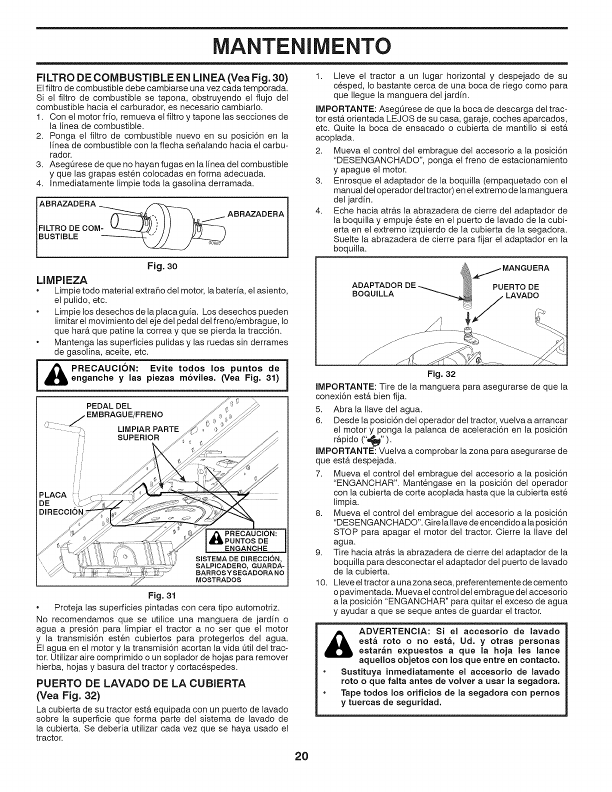
MANTENIMENTO
FILTRO DE COMBUSTIBLE EN LINEA (Vea Fig. 30)
El filtro de combustible debe cambiarse una vez cada temporada.
Si et filtro de combustible se tapona, obstruyendo et flujo det
combustible hacia et carburador, es necesario cambiarlo.
1. Con el motor frio, remueva et filtro y tapone las secciones de
la linea de combustible.
2. Ponga el filtro de combustible nuevo en su posici6n en la
linea de combustible con la flecha sehalando hacia et carbu-
rador.
3. AsegQrese de que no hayan fugas en ta lfnea del combustible
y que las grapas esten colocadas en forma adecuada.
4. Inmediatamente limpie toda la gasolina derramada.
ABRAZADERAMT__, / ABRAZADERA
FILTRO DE CO ,/
BUSTIBLE .... ---_
Fig. 3o
LIMPIEZA
•Limpie todo material extraho det motor, la bateria, et asiento,
et putido, etc.
• Limpie los desechos de la placa guia. Los desechos pueden
limitar el movimiento det eje det pedal det freno/embrague, Io
que har& que patine la correa y que se pierda la tracci6n.
Mantenga las superficies pulidas y las ruedas sin derrames
de gasolina, aceite, etc.
iA ..c uco..v,e,o°o.os ontos°ei
enganche y las piezas mdviles. (Vea Fig. 31)
PEDAL DEL
/ EMBRAGUE/FRENO
'L:!::::: :<x, LIMPIAR PARTE
,', SUPERIOR
PLAOA
DE
MOSTRADOS
Fig. 31
•Proteja las superficies pintadas con cera tipo automotriz.
No recomendamos que se utitice una manguera de jardin o
agua a presi6n para limpiar el tractor a no ser que et motor
y la transmisi6n esten cubiertos para protegerlos det agua.
El agua en et motor y la transmisi6n acortan ta vida Otil del trac-
tor. Utilizar aire comprimido o un soplador de hojas para remover
hierba, hojas y basura det tractor y cortacespedes.
PUERTO DE LAVADO DE LA CUBIERTA
(Vea Fig. 32)
La cubierta de su tractor esta equipada con un puerto de lavado
sobre la superficie que forma parte del sistema de lavado de
la cubierta. Se deberia utilizar cada vez que se haya usado et
tractor.
1. Lleve et tractor a un lugar horizontal y despejado de su
cesped, Io bastante cerca de una boca de riego como para
que Ilegue la manguera det jardin.
IMPORTANTE: AsegQrese de que la boca de descarga det trac-
tor esta orientada LEJOS de su casa, garaje, coches aparcados,
etc. Quite la boca de ensacado o cubierta de mantillo si est&
acoptada.
2. Mueva el control det embrague del accesorio a la posici6n
"DESENGANCHADO", ponga et freno de estacionamiento
y apague et motor.
3. Enrosque el adaptador de la boquilla (empaquetado con el
manual del operador det tractor) en et extremo de la manguera
det jardin.
4. Eche hacia atr&s la abrazadera de cierre del adaptador de
la boquilla y empuje este en et puerto de lavado de la cubi-
erta en et extremo izquierdo de la cubierta de la segadora.
Suelte la abrazadera de cierre para fijar el adaptador en la
boquitla.
ADAPTADOR DE
BOQUILLA
MANGUERA
PUERTO DE
LAVADO
Fig. 32
IMPORTANTE: Tire de la manguera para asegurarse de que la
conexi6n est& bien fija.
5. Abra la Ilave det agua.
6. Desde la posici6n del operador det tractor, vuelva a arrancar
el motor y ponga la palanca de aceteraci6n en la posici6n
rapido ("=_IP").
IMPORTANTE: Vuelva a comprobar la zona para asegurarse de
que est& despejada.
7. Mueva el control del embrague det accesorio a la posici6n
"ENGANCHAR". Mantengase en la posici6n det operador
con la cubierta de corte acoptada hasta que la cubierta este
limpia.
8. Mueva el control del embrague del accesorio a la posici6n
"DESENGANCHADO". Gire la Ilavede encendido a la posici6n
STOP para apagar et motor det tractor. Cierre la Ilave det
agua.
9. Tire hacia atr&s ta abrazadera de cierre del adaptador de la
boquilta para desconectar et adaptador det puerto de lavado
de la cubierta.
10. Ueve et tractor a unazona seca, preferentemente de cemento
o pavimentada. Mueva el control det embrague del accesorio
a la posici6n "ENGANCHAR" para quitar el exceso de agua
y ayudar a que se seque antes de guardar el tractor.
ADVERTENCIA: SJ el accesorio de lavado
est_ roto o no est,, Ud. y otras personas
estar_n expuestos a que la hoja les lance
aquellos objetos con los que entre en contacto.
• SustJtuya inmedJatamente el accesorio de lavado
roto o que falta antes de volver a usar la segadora.
•Tape todos los orJficios de la segadora con pernos
y tuercas de seguridad.
20
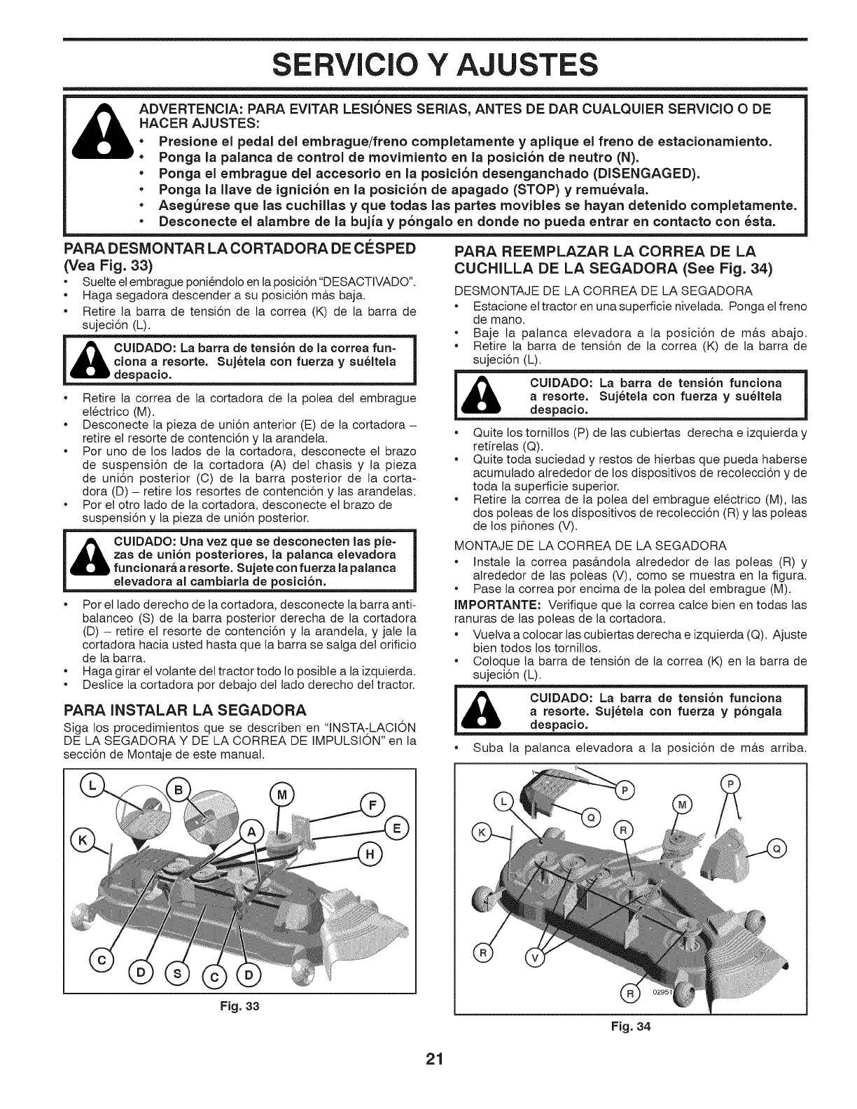
SERVICIO Y AJUSTES
r
_DVERTENCIA: PARA EVITAR LESIONES SERIAS, ANTES DE DAR CUALQUIER SERVICIO ODE
HACER AJUSTES:
•Presione el pedal del embrague/freno completamente yaplique el freno de estacionamiento.
•Ponga la palanca de control de movimiento en la posici6n de neutro (N).
•Ponga el embrague del accesorio en la posici6n desenganchado (DISENGAGED).
•Ponga la Ilave de ignici6n en la posici6n de apagado (STOP) y remu_vala.
• AsegSrese que las cuchillas y que todas las partes movibles se hayan detenido completamente.
•Desconecte el alambre de la bujia y p6ngalo en donde no pueda entrar en contacto con _sta.
PARA DESMONTAR LA CORTADORA DE ClaSPED
(Vea Fig. 33)
•Suette el embrague poniendoto en la posici6n "DESACTIVADO".
•Haga segadora descender a su posici6n m&s baja.
•Retire la barra de tensi6n de la correa (K) de la barra de
sujeci6n (L).
ciona a resorte. Suj6tela con fuerza y su_ltela
despacio.
•Retire la correa de la cortadora de la polea del embrague
etectrico (M).
•Desconecte la pieza de uni6n anterior (E) de la cortadora -
retire et resorte de contenci6n y la arandela.
•Pot uno de los lados de la cortadora, desconecte et brazo
de suspensi6n de la cortadora (A) del chasis y la pieza
de uni6n posterior (C) de la barra posterior de la corta-
dora (D) - retire los resortes de contenci6n y las arandelas.
•Por el otro lado de la cortadora, desconecte et brazo de
suspensi6n y la pieza de uni6n posterior.
_ CUIDADO: Una vez que se desconecten las pie-
zas de uni6n posteriores, la palanca elevadora
funcionar_ a resorte. Sujete con fuerza la palanca
elevadora al cambiarla de posici6n.
•Por el lado derecho de la cortadora, desconecte la barra anti-
balanceo (S) de la barra posterior derecha de la cortadora
(D) - retire el resorte de contenci6n y la arandela, y jale la
cortadora hacia usted hasta que la barra se salga det orificio
de la barra.
•Haga girar etvolante del tractor todo Io posible a ta izquierda.
•Deslice la cortadora pot debajo det lado derecho det tractor.
PARA INSTALAR LA SEGADORA
Siga los procedimientos que se describen en "INSTA-LACION
DE LA SEGADORA Y DE LA CORREA DE IMPULSION" en la
secci6n de Montaje de este manual.
PARA REEIVIPLAZAR LA CORREA DE LA
CUCHILLA DE LA SEGADORA (See Fig. 34)
DESMONTAJE DE LA CORREA DE LA SEGADORA
•Estacione et tractor en una superficie nivetada. Ponga et freno
de mano.
•Baje la palanca etevadora a la posici6n de m&s abajo.
•Retire la barra de tensi6n de la correa (K) de la barra de
sujeci6n (L).
despacio. J
a resorte_ con fuerza y su_ltela
•Quite los tornitlos (P) de las cubiertas derecha e izquierda y
retirelas (Q).
•Quite toda suciedad y restos de hierbas que pueda haberse
acumutado alrededor de los dispositivos de recolecci6n y de
toda la superficie superior.
•Retire la correa de la potea det embrague electrico (M), las
dos poleas de los dispositivos de recolecci6n (R) y las poleas
de los pihones (V).
MONTAJE DE LA CORREA DE LA SEGADORA
•Instale la correa pas&ndota alrededor de las poteas (R) y
alrededor de las poleas (V), como se muestra en la figura.
•Pase la correa por encima de la polea del embrague (M).
IMPORTANTE: Verifique que la correa calce bien en todas las
ranuras de las poteas de la cortadora.
•Vuelva a cotocar las cubiertas derecha e izquierda (Q). Ajuste
bien todos los tornillos.
•Coloque ta barra de tensi6n de la correa (K) en la barra de
sujeci6n (L).
i CUIDADO: La barra de tensi6n funciona i
despacio.
a resorte. Suj6tela con fuerza y p6ngala |
•Suba la palanca etevadora a la posici6n de m&s arriba.
Fig. 33
Fig. 34
21
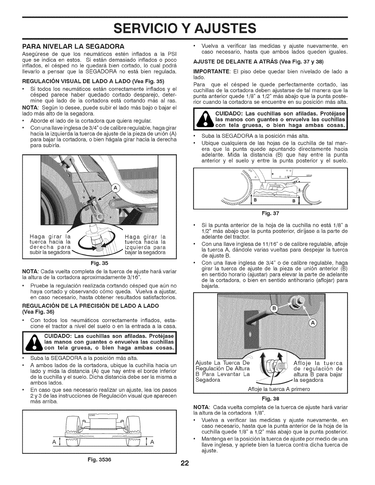
SERVlCIO Y AJUSTES
PARA NIVELAR LA SEGADORA
AsegQrese de que los neum&ticos esten inflados a la PSi
que se indica en estos. Si estan demasiado inftados o poco
inflados, et cesped no le quedar_, bien cortado, 1o cual podr_.
Ilevarlo a pensar que la SEGADORA no est,. bien regutada.
REGULACI6N VISUAL DE LADO ALADO (Vea Fig. 35)
•Si todos los neum&ticos est_.n correctamente inftados y el
cesped parece haber quedado cortado desparejo, deter-
mine qua lado de la cortadora est,. cortando m_.s al ras.
NOTA: SegOn Io desee, puede subir et lado m_.s bajo o bajar et
lado m_.s alto de la segadora.
• Aborde et lado de la cortadora que quiera regular.
• Con una Ilave ingtesa de 3/4" o de calibre regutabte, haga girar
hacia la izquierda la tuerca de ajuste de la pieza de uni6n (A)
para bajar la cortadora, o bien ha.gala girar hacia la derecha
para subirla.
Haga girar ta Haga girar la
tuerca hacia la tuerca nacla la
derecha para ..'.'. izquierda para
subir la segadora _ bajar la segadora
Fig. 35
NOTA: Cada vuelta completa de la tuerca de ajuste har& variar
la altura de la cortadora aproximadamente 3/16".
Pruebe la regulaci6n realizada cortando cesped que a0n no
haya cortado y observando c6mo queda. Vuetva a ajustar,
en caso necesario, hasta obtener resultados satisfactorios.
REGULACI6N DE LA PRECISI6N DE LADO ALADO
(Vea Fig, 36)
* Con todos los neumAticos correctamente inflados, esta-
clone et tractor a nivet det sueto o en la entrada a la casa.
j cUIDADO:Laao°oh,laaao°afHadaa.P o iaaoj
_,con tela gruesa, o bien haga ambas cosas.
|las manos con guantes o envuelva las cuchJllas |
* Suba la SEGADORA a la posici6n m_.s alta.
* A ambos lados de la cortadora, ubique ta cuchilla hacia un
lado y mida la distancia (A) que hay entre et borde inferior
de la cuchilla y el suelo. Dicha distancia debe ser la misma a
ambos lados.
* En caso que sea necesario realizar un ajuste, lea los pasos
2 y 3 de las instrucciones de Regutaci6n visual que aparecen
m_.s arriba.
....................,:_ .E_
A; tA
* Vuelva a verificar las medidas y ajuste nuevamente, en
caso necesario, hasta que ambos lados queden iguales.
AJUSTE DE DELANTE AATRAS (Vea Fig. 37 y 38)
IMPORTANTE: Et piso debe quedar bien nivetado de lado a
lado.
Para que et cesped le quede perfectamente cortado, las
cuchitlas de la cortadora deben ajustarse de tal manera que la
punta anterior quede 1/8" a 1/2" m_.s abajo que la punta poste-
rior cuando la cortadora se encuentre en su posici6n m_.s alta.
i _JL CUIDADO_ afiladas. Prot_jase
_las manos con guantes oenvuelva las cuchJllas
IL,i_con tela gruesa, o bien haga ambas cosas.
Suba la SEGADORA a la posici6n m&s alta.
Ubique cualquiera de tas hojas de la cuchilla de tal man-
era que la punta quede apuntando directamente hacia
adetante. Mida la distancia (B) que hay entre la punta
anterior y et sueto y entre la punta posterior y et sueto.
Fig. 37
•Si la punta anterior de la hoja de la cuchitla no est& 1/8" a
1/2" m&s abajo que la punta posterior, dir[jase a la parte de
adetante det tractor.
•Con una Ilave inglesa de 11/16" o de calibre regulabte, afloje
la tuerca A, d&ndole varias vuettas para despejar la tuerca
de ajuste B.
•Con una Ilave inglesa de 3/4" o de calibre regulabte, haga
girar la tuerca de ajuste de la pieza de uni6n anterior (B)
en sentido horario (ajustar) para elevar la parte de adelante
de la cortadora, o bien en sentido antihorario (aftojar) para
bajarla.
Ajuste LaTuerca De Afloje la tuerca
Regulaci6n De Altura de regulaci6n de
B Para Levantar La altura B para bajar
Segadora / --"adora
Afloje la tuerca A primero
Fig. 38
NOTA: Cada vuelta compteta de la tuerca de ajuste har& variar
la altura de la cortadora 1/8".
•Vuelva a verificar las medidas y ajuste nuevamente, en
caso necesario, hasta que la punta anterior de la hoja de la
cuchitla quede 1/8" a 1/2" m_.s abajo que la punta posterior.
•Mantenga en la posici6n la tuerca de ajuste por medio de una
Ilave ingtesa, y apriete bien la tuerca contra dicha tuerca de
ajuste.
Fig, 3536 22
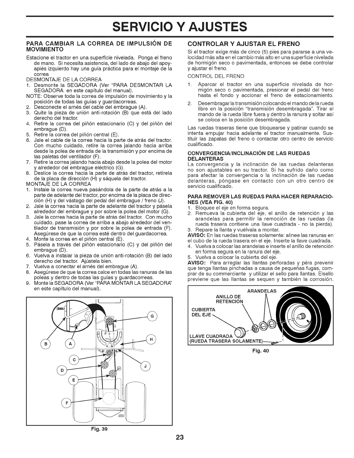
SERVICIO Y AJUSTES
PARA CAMBIAR LA CORREA DE iMPULSION DE
MOVIMIENTO
Estacione el tractor en una superficie nivelada. Ponga el freno
de mano. Si necesita asistencia, del lado de abajo del apoy-
apies izquierdo hay una guia pr&ctica para el montaje de la
correa
DESMONTAJE DE LA CORREA
1. Desmonte la SEGADORA (Ver "PARA DESMONTAR LA
SEGADORA en este capitulo del manual).
NOTE: Observe toda la correa de impulsi6n de movimiento y la
posici6n de todas las guias y guardacorreas.
2. Desconecte el arnes del cable del embrague (A).
3. Quite la pieza de uni6n anti-rotaci6n (B) que est& del lado
derecho del tractor.
4. Retire la correa del pifl6n estacionario (C) y del pifl6n del
embrague (D).
5. Retire la correa del pifl6n central (E).
6. Jale el cable de la correa hacia la parte de atr&s del tractor.
Con mucho cuidado, retire la correa jalando hacia arriba
desde la polea de entrada de la transmisi6n y por encima de
las paletas del ventilador (F).
7. Retire la correa jalando hacia abajo desde la polea del motor
y alrededor del embrague electrico (G).
8. Deslice la correa hacia la parte de atr&s del tractor, retirela
de la placa de direcci6n (H) y s&quela del tractor.
MONTAJE DE LA CORREA
1. Instale la correa nueva pas&ndola de la parte de atr&s a la
parte de adelante del tractor, por encima de la placa de direc-
ci6n (H) y del v&stago del pedal del embrague /freno (J).
2. Jale la correa hacia la parte de adelante del tractor y p&sela
atrededor del embrague y por sobre la polea del motor (G).
3. Jale la correa hacia la parte de atr&s del tractor. Con mucho
cuidado, pase la correa de arriba a abajo alrededor del ven-
tilador de transmisi6n y por sobre la polea de entrada (F).
Aseg0rese de que la correa este dentro del guardacorrea.
4. Monte la correa en el pifl6n central (E).
5. P&sela a traves del pifl6n estacionario (C) y del pifl6n del
embrague (D).
6. Vuelva a instalar la pieza de uni6n anti-rotaci6n (B) del lado
derecho del tractor. Aj0stela bien.
7. Vuelva a conectar el arnes del embrague (A).
8. AsegQrese de que la correa calce en todas las ranuras de las
poleas y dentro de todas las guias y guardacorreas.
9. Monte la SEGADORA (Ver"PARA MONTAR LA SEGADORA'
en este capitulo del manual).
CONTROLAR Y AJUSTAR EL FRENO
Si el tractor exige m&s de cinco (5) pies para pararse a una ve-
Iocidad m&s alta en et cambio m&s alto en una superficie nivetada
de hormig6n seco o pavimentada, entonces se debe controlar
y ajustar et freno.
CONTROL DEL FRENO
1. Aparcar el tractor en una superficie nivelada de hor-
mig6n seco o pavimentada, presionar et pedal del freno
hasta et fondo y accionar el freno de estacionamiento.
2. Desembragar latransmisi6n colocando el mando de la rueda
libre en la posici6n "transmisi6n desembragada". Tirar el
mando de la rueda libre fuera y dentro ta ranura y soltar asi
se cotoca en la posici6n desembragada.
Las ruedas traseras tiene que btoquearse y patinar cuando se
intenta empujar hacia adelante et tractor manuatmente. Sus-
tituir las zapatas det freno o contactar otro centro de servicio
cualificado.
CONVERGENCIA/INCLINACI6N DE LAS RUEDAS
DELANTERAS
La convergencia y la inclinaci6n de las ruedas delanteras
no son ajustabtes en su tractor. Si ha sufrido daflo como
para afectar la convergencia o la inclinaci6n de las ruedas
delanteras, p6ngase en contacto con un otro centro de
servicio cualificado.
PARA REMOVER LAS RUEDAS PARA HACER REPARACIO-
NES (VEA FiG, 40)
1. Bloquee el eje en forma segura.
2. Remueva la cubierta det eje, el anillo de retenci6n y las
arandelas para permitir la remoci6n de las ruedas (la
rueda trasera contiene una Ilave cuadrada -no la pierda).
3. Repare la Ilanta y vuelvala a montar.
AVlSO: En las ruedas traseras solamente: alinee las ranuras en
et cubo de la rueda trasera en el eje. Inserte la Ilave cuadrada.
4. Vuetva a colocar las arandetas e inserte et anitlo de retenci6n
en forma segura en la ranura det eje.
5. Vuetva a colocar la cubierta det eje.
AVISO: Para arreglar las Ilantas perforadas y pera prevenir
que tenga Ilantas pinchadas a causa de pequeflas fugas, com-
prar de su commerciante y utilizar et setlo para Ilantas. Etsello
previene que las Ilantas se sequen y tambien la corrosi6n.
ANILLO DE
RETENCION
CUBIERTA
DEL
ARANDELAS
LLAVE
RUEDA TRASERA
Fig. 4O
Fig. 39
23
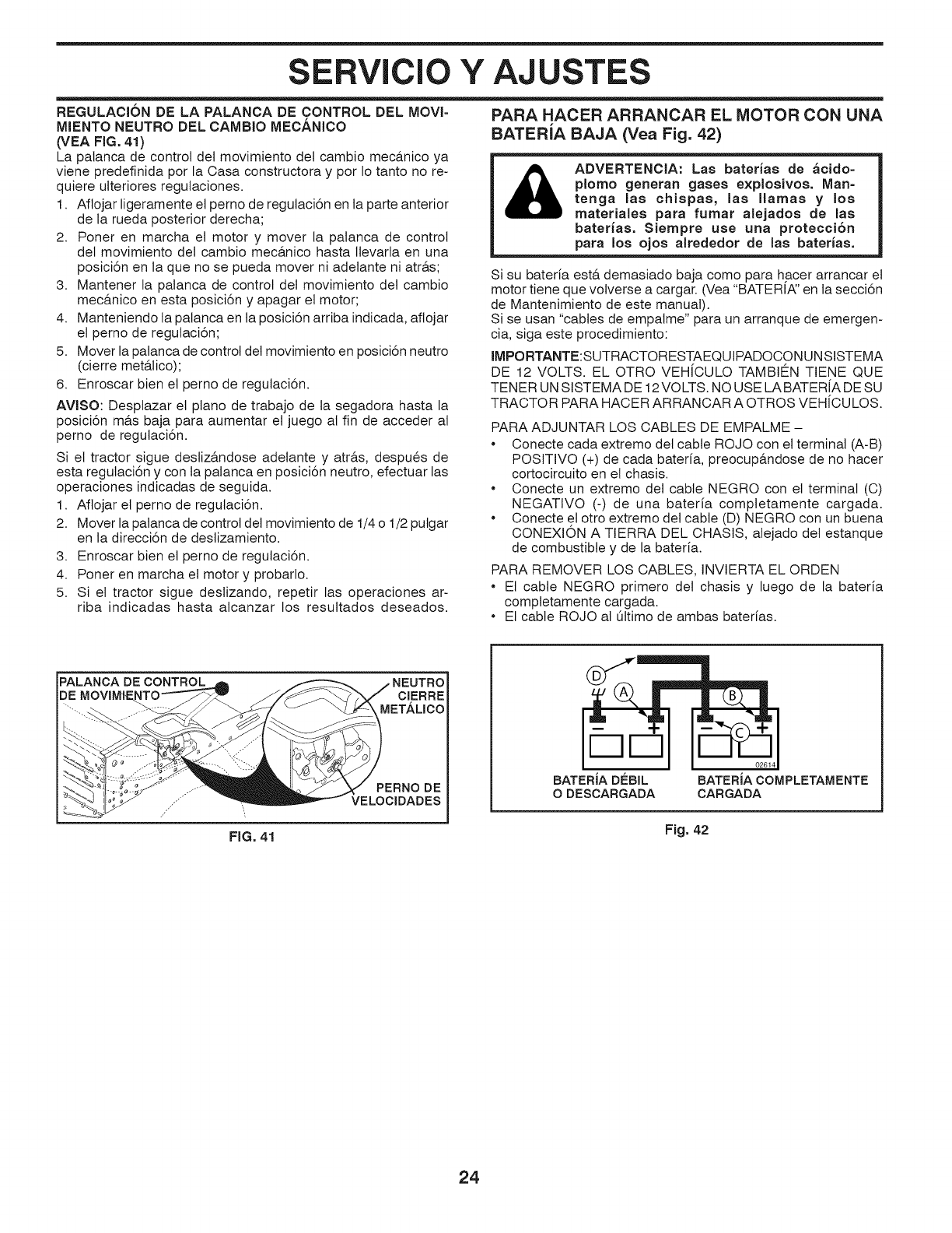
SERVICIO Y AJUSTES
REGULACION DE LA PALANCA DE CONTROL DEL MOVI-
MIENTO NEUTRO DEL CAMBIO MECANICO
(VEA FIG. 41)
La palanca de control del movimiento del cambio mec&nico ya
viene predefinida pot la Casa constructora y pot Io tanto no re-
quiere ulteriores regutaciones.
1. Aflojar ligeramente et perno de regutaci6n en ta parte anterior
de la rueda posterior derecha;
2. Porter en marcha et motor y mover la palanca de control
del movimiento det cambio mec&nico hasta llevarta en una
posici6n en la que no se pueda mover ni adelante ni atr&s;
3. Mantener la patanca de control del movimiento det cambio
mec&nico en esta posici6n y apagar et motor;
4. Manteniendo la patanca en ta posici6n arriba indicada, aflojar
et perno de regutaci6n;
5. Mover la palanca de control del movimiento en posici6n neutro
(cierre met&lico);
6. Enroscar bien et perno de regutaci6n.
AVISO: Desplazar el piano de trabajo de la segadora hasta la
posici6n m&s baja para aumentar et juego al fin de acceder al
perno de regutaci6n.
Si et tractor sigue destiz&ndose adelante y atr&s, despues de
esta regulaci6n y con ta palanca en posici6n neutro, efectuar las
operaclones indicadas de seguida.
1. Aflojar et perno de regutaci6n.
2. Mover la palanca de control del movimiento de 1/4 o 1/2 putgar
en la direcci6n de destizamiento.
3. Enroscar bien et perno de regutaci6n.
4. Poner en marcha el motor y probarlo.
5. Si et tractor sigue deslizando, repetir las operaciones ar-
riba indicadas hasta alcanzar los resuttados deseados.
PARA HACER ARRANCAR EL MOTOR CON UNA
BATERiA BAJA (Vea Fig. 42)
ADVERTENCIA: Las baterias de _cido=
plomo generan gases explosivos. Man=
tenga las chispas, las llamas y los
materiales para fumar aiejados de las
baterias. Siempre use una protecci6n
para los ojos alrededor de las baterias,
Si su bateria est& demasiado baja como para hacer arrancar el
motor tiene que volverse a cargar. (Vea "BATER[A:' en la secci6n
de Mantenimiento de este manual).
Si se usan "cables de empalme" para un arranque de emergen-
cia, siga este procedimiento:
IMPORTANTE:SUTRACTORESTAEQUIPADOCON UN SISTEMA
DE 12 VOLTS. EL OTRO VEH[CULO TAMBIE_N TIENE QUE
TENER UN SISTEMA DE 12VOLTS. NO USE LA BATER[A DE SU
TRACTOR PARA HACER ARRANCAR A OTROS VEH[CULOS.
PARA ADJUNTAR LOS CABLES DE EMPALME -
• Conecte cada extremo det cable ROJO con el terminal (A-B)
POSmVO (4-)de cada bateria, preocup&ndose de no hacer
cortocircuito en et chasis.
• Conecte un extremo del cable NEGRO con el terminal (C)
NEGATIVO (-) de una bateria comptetamente cargada.
• Conecte el otro extremo det cable (D) NEGRO con un buena
CONEXION A TIERRA DEL CHASIS, alejado det estanque
de combustible y de la bateria.
PARA REMOVER LOS CABLES, INVIERTA EL ORDEN
• El cable NEGRO primero det chasis y luego de la bateria
completamente cargada.
• El cable ROJO al [31timode ambas baterias.
PALANCA DE CONTROL
I
FIG. 41
CIERRE
METALICO
PERNO DE
VELOCIDADES
BATERiA DEBIL BATERiA COMPLETAMENTE
O DESCARGADA CARGADA
Fig. 42
24
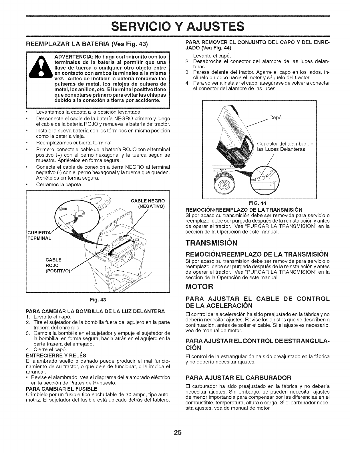
SERVICIO Y AJUSTES
REEMPLAZAR LA BATERIA (Vea Fig. 43)
ADVERTENCIA: No hags cortocircuito con los
terminales de la bateria al permitir que una
llave de tuerca ocualquier otto objeto entre
en contacto con ambos terminales a la raisins
vez. Antes de instalar la bateria remueva las
pulseras de metal, los relojes de pulsera de
metal, los anillos, etc. El terminal positivo tiene
que conectarse primero para evitar las chispas
dsbido ala consxi6n a tierra pot accidents.
PARA REMOVER EL CONJUNTO DEL CAPO Y DEL ENRE=
JADO (Vea Fig. 44)
1. Levante el cap6.
2. Desabroche et conector det alambre de las luces detan-
teras.
3. P&rese detante del tractor. Agarre el cap6 en los lados, in-
clfnelo un poco hacia et motor y s&quelo del tractor.
4. Para volver a instalar et cap6, asegOrese de volver a conectar
et conector det alambre de las luces.
Levantamos la capota a la posici6n levantada.
Desconecte et cable de la bateria NEGRO primero y luego
et cable de la bateria ROJO y remueva la bateria det tractor.
Instale la nueva bateria con los terminos en misma posici6n
como la bateria vieja.
Reemptazamos cubierta terminal.
Primero, conecte el cable de la bateria ROJO con et terminal
positivo (4-) con et perno hexagonal y la tuerca segQn se
muestra. Aprietelos en forma segura.
Conecte et cable de conexi6n a tierra NEGRO al terminal
negativo (-) con et perno hexagonal y la tuerca que queden.
Aprietelos en forma segura.
Cerramos la capota.
CABLE NEGRO
(NEGATIVO)
TERMINAL
CABLE
ROJO
(POSITIVO I
_\\\\\
Fig. 43
PARA CAMBIAR LA BOMBILLA DE LA LUZ DELANTERA
1. Levante et cap6.
2. Tire el sujetador de ta bombilla fuera det agujero en la parte
trasera det enrejado.
3. Cambie la bombilla en et sujetador y empuje el sujetador de
la bombilta, en forma segura, hacia atr&s en et agujero en la
parte trasera det enrejado.
4. Cierre et cap6.
ENTRECIERRE YRELES
Et alambrado suetto o dahado puede producir et mal funcio-
namiento de su tractor, o que deje de funcionar, o le impida et
arrancar.
* Revise et alambrado. Vea el diagrama det alambrado etectrico
en ta secci6n de Partes de Repuesto.
PARA CAMBIAR EL FUSIBLE
C_,mbieto por un fusible tipo enchufable de 30 amps, tipo auto-
motriz. Et sujetador det fusible est& ubicado detr&s det tabtero.
\\_Cap6
Conector del alambre de
las Luces Delanteras
FIG. 44
REMOCION/REEMPLAZO DE LA TRANSMISION
Si por acaso su transmisi6n debe ser removida para servicio o
reemplazo, debe ser purgada despues de la reinstalaci6n y antes
de operar el tractor. Vea "PURGAR LA TRANSMISION" en la
secci6n de la Operaci6n de este manual.
TRANSMISION
REMOCION/REEMPLAZO DE LA TRANSIVIISION
Si por acaso su transmisi6n debe ser removida para servicio o
reemplazo, debe ser purgada despues de la reinstalaci6n y antes
de operar et tractor. Vea "PURGAR LA TRANSMISION" en la
secci6n de la Operaci6n de este manual.
MOTOR
PARA AJUSTAR EL CABLE DE CONTROL
DE LA ACELERACION
El control de la aceleraci6n ha sido preajustado en ta f&brica y no
deberfa necesitar ajustes. Revise los ajustes que se describen a
continuaci6n, antes de soltar et cable. Si et ajuste es necesario,
vea de manual de motor.
PARAAJ USTAR EL CONTROL DE ESTRANGULA-
Cl6N
Et control de la estrangutaci6n ha sido preajustado en la f&brica
y no deberia necesitar ajustes.
PARA AJUSTAR EL CARBURADOR
Et carburador ha sido preajustado en la f&brica y no deberia
necesitar ajustes. Sin embargo, se pueden necesitar ajustes
de menor importancia para compensar por las diferencias en el
combustible, temperatura, altura o carga. Si et carburador nece-
sita ajustes, vea de manual de motor.
25
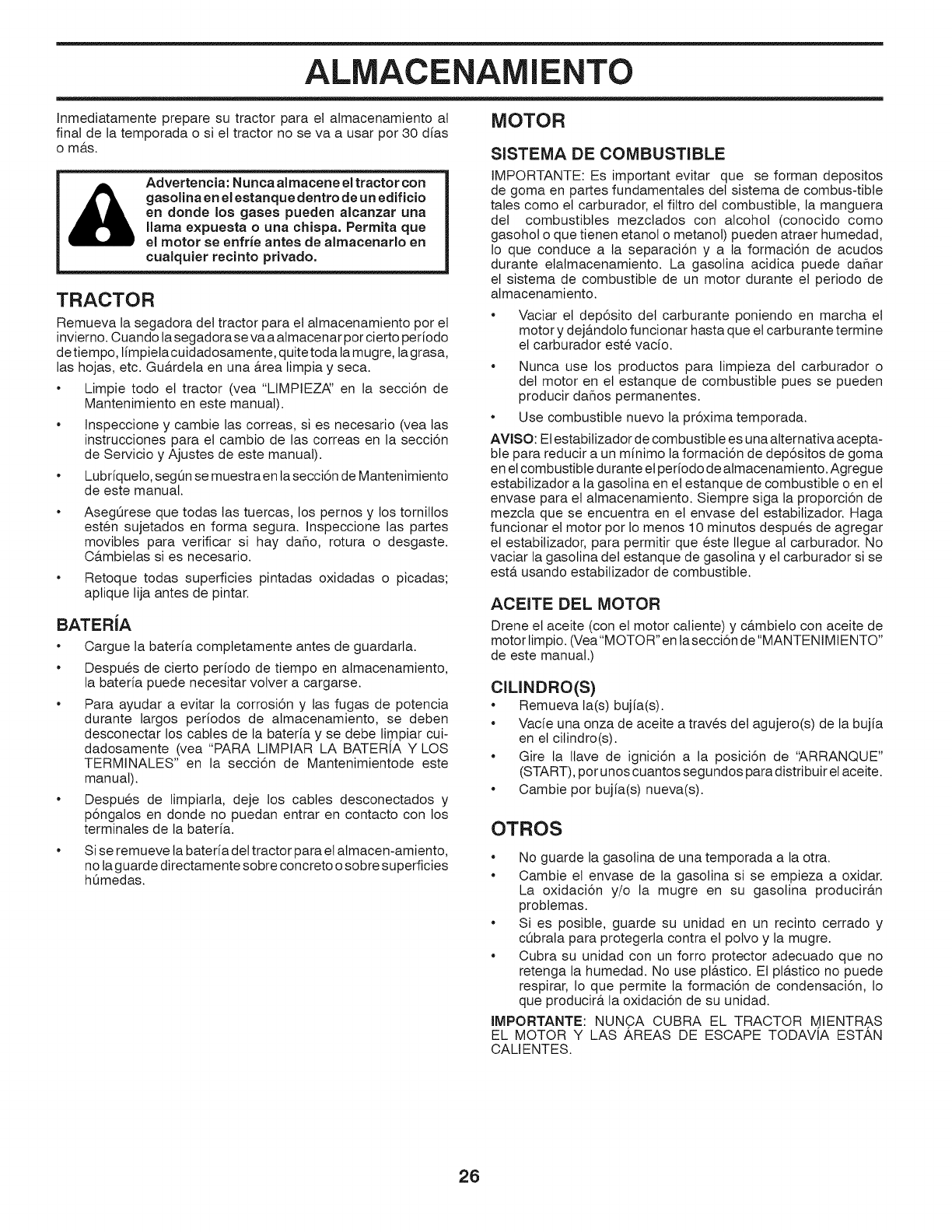
ALMACENAMIENTO
Inmediatamente prepare su tractor para et almacenamiento at
final de la temporada o si et tractor no se va a usar pot 30 dfas
o m&s.
Advertencia: Nunca almacene el tractor con
gasolina en el estanque dentro de un edificio
en donde los gases pueden alcanzar una
llama expuesta ouna chispa. Permita que
el motor se enfrie antes de almacenarlo en
cualquier recinto privado.
TRACTOR
Remueva la segadora del tractor para et atmacenamiento por el
invierno. Cuando tasegadora se va a almacenar por cierto periodo
de tiempo, limpiela cuidadosamente, quite toda la mugre, la grasa,
las hojas, etc. Gu&rdeta en una &rea limpia y seca.
Limpie todo et tractor (vea "LIMPIEZA:' en la secci6n de
Mantenimiento en este manual).
Inspeccione y cambie las correas, si es necesario (vea tas
instrucciones para et cambio de las correas en la secci6n
de Servicio y Ajustes de este manual).
Lubriqueto, segOn se muestra en lasecci6n de Mantenimiento
de este manual.
AsegOrese que todas tas tuercas, los pernos y los tornillos
esten sujetados en forma segura. Inspeccione las partes
movibtes para verificar si hay daho, rotura o desgaste.
C&mbietas si es necesario.
Retoque todas superficies pintadas oxidadas o picadas;
aptique lija antes de pintar.
BATERiA
Cargue la bateria comptetamente antes de guardarla.
Despues de cierto periodo de tiempo en almacenamiento,
la bateria puede necesitar volver a cargarse.
Para ayudar a evitar la corrosi6n y las fugas de potencia
durante largos periodos de almacenamiento, se deben
desconectar los cables de la bateria y se debe limpiar cui-
dadosamente (vea "PARA LIMPIAR LA BATERIA Y LOS
TERMINALES" en la secci6n de Mantenimientode este
manual).
Despues de limpiarla, deje los cables desconectados y
p6ngalos en donde no puedan entrar en contacto con los
terminates de la bateria.
Si se remueve la bateria det tractor para et almacen-amiento,
no la guarde directamente sobre concreto o sobre superficies
h0medas.
MOTOR
SISTEMA DE COMBUSTIBLE
IMPORTANTE: Es important evitar que se forman depositos
de goma en partes fundamentales det sistema de combus-tible
tales como el carburador, el filtro del combustible, la manguera
del combustibles mezclados con alcohol (conocido como
gasohot o que tienen etanot o metanol) pueden atraer humedad,
Io que conduce a ta separaci6n y a la formaci6n de acudos
durante etalmacenamiento. La gasolina acidica puede dahar
el sistema de combustible de un motor durante et periodo de
almacenamiento.
Vaciar et dep6sito del carburante poniendo en marcha el
motor y dej&ndoto funcionar hasta que et carburante termine
el carburador este vacio.
Nunca use los productos para limpieza del carburador o
det motor en et estanque de combustible pues se pueden
producir dahos permanentes.
Use combustible nuevo la pr6xima temporada.
AVISO: Et estabilizador de combustible es una alternativa acepta-
bte para reducir a un minimo la formaci6n de dep6sitos de goma
en et combustible durante et periodo de almacenamiento. Agregue
estabilizador a la gasolina en et estanque de combustible o en et
envase para et almacenamiento. Siempre siga la proporci6n de
mezcla que se encuentra en el envase del estabilizador. Haga
funcionar et motor por Io menos 10 minutos despues de agregar
et estabitizador, para permitir que este Ilegue al carburador. No
vaciar la gasotina del estanque de gasotina y et carburador si se
est& usando estabilizador de combustible.
ACEITE DEL MOTOR
Drene et aceite (con et motor catiente) y c&mbieto con aceite de
motor limpio. (Vea"MOTOR" en la secci6n de "MANTENIMIENTO"
de este manual.)
ClLINDRO(S)
* Remueva la(s) bujia(s).
* Vacfe una onza de aceite a traves det agujero(s) de la bujia
en el cilindro(s).
* Gire la Ilave de ignici6n a la posici6n de 'ARRANQUE"
(START), pot unos cuantos segundos para distribuir elaceite.
* Cambie pot bujia(s) nueva(s).
OTROS
No guarde la gasolina de una temporada a la otra.
Cambie el envase de la gasolina si se empieza a oxidar.
La oxidaci6n y/o la mugre en su gasolina producir&n
probtemas.
Si es posibte, guarde su unidad en un recinto cerrado y
c0brala para protegerla contra et polvo y la mugre.
Cubra su unidad con un forro protector adecuado que no
retenga la humedad. No use pt&stico. El pl&stico no puede
respirar, Io que permite la formaci6n de condensaci6n, Io
que producir& la oxidaci6n de su unidad.
IMPORTANTE: NUNCA CUBRA EL TRACTOR MIENTRAS
EL MOTOR Y LAS AREAS DE ESCAPE TODAVIA ESTAN
CALIENTES.
26
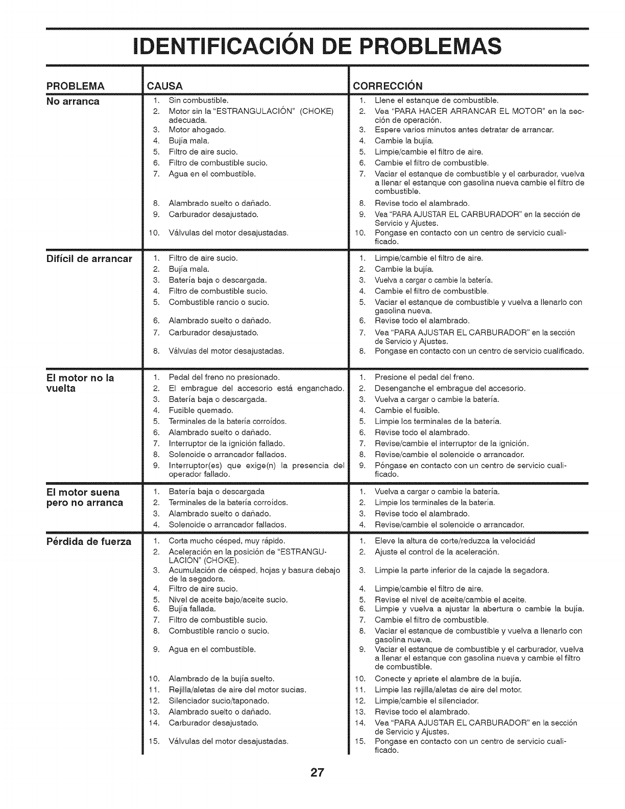
f
IDENTIFICACION DE PROBLEMAS
PROBLEMA
NO arral3ca
Dificil de arrancar
El motor no la
vuelta
El motor suena
pero I_o arranca
P_rdida de fuerza
CAUSA
1. Sin combustible.
2. Motor sin la"ESTRANGULACION" (CHOKE)
adecuada.
3. Motor ahogado.
4. Bujia mala.
5. Filtro de aire sucio.
6. Filtro de combustible sucio.
7. Agua en el combustible.
8. Alambrado suelto o daSado.
9. Carburador desajustado.
10. V&lvulas del motor desajustadas.
CORRECClON
1. Llene el estanque de combustible.
2. Vea "PARA HACER ARRANCAR EL MOTOR" en la sec-
ci6n de operaci6n.
3. Espere varios minutos antes detratar de arrancar.
4. Cambie la bujia.
5. Limpie/cambie el filtro de aire.
6. Cambie el filtro de combustible.
7. Maciar el estanque de combustible y el carburador, vuelva
a Ilenar el estanque con gasolina nueva cambie el filtro de
combustible.
8. Revise todo el alambrado.
9. Vea "PARA AJUSTAR EL CARBURADOR" en la secci6n de
Servicio y Ajustes.
10. Pongase en contacto con un centro de servicio cuali-
ficado.
1. Filtro de aire sucio.
2. Bujia mala.
3. Bateria baja o descargada.
4. Filtro de combustible sucio.
5. Combustible rancio o sucio.
6. Alambrado suelto o da_ado.
7. Carburador desajustado.
8. V&lvulas del motor desajustadas.
1. Pedal del freno no presionado.
2. El embrague del accesorio est& enganchado.
1. Limpie/cambie el filtro de aire.
2. Cambie la bujia.
3. Vuelva a cargar o cambie la bateria.
4. Cambie el filtro de combustible.
5. Maciar el estanque de combustible y vuelva a Ilenarlo con
gasolina nueva.
6. Revise todo el alambrado.
7. Vea "PARA AJUSTAR EL CARBURADOR" en la secci6n
de Servicio y Ajustes.
8. Pongase en contacto con un centro de servicio cualificado.
1. Presione el pedal del freno.
2. Desenganche el embrague del accesorio.
3. Bateria baja o descargada.
4. Fusible quemado.
5. Terminales de la bateria corroidos.
6. Alambrado suelto o daSado.
7. Interruptor de la ignici6n fallado.
8. Solenoide o arrancador fallados.
3. Vuelva a cargar o cambie la bateria.
4. Cambie el fusible.
5. Limpie los terminales de la bateria.
6. Revise todo el alambrado.
7. Revise/cambie el interruptor de la ignici6n.
8. Revise/cambie el solenoide o arrancador.
9. Interruptor(es) que exige(n) la presencia del
operador fallado.
1. Bateria baja o descargada
2. Terminales de la bateria corroidos.
3. Alambrado suelto o daSado.
4. Solenoide o arrancador fallados.
9. P6ngase en contacto con un centro de servicio cuali-
ficado.
1. Vuelva a cargar o cambie la bateria.
2. Limpie los terminales de la bateria.
3. Revise todo el alambrado.
4. Revise/cambie el solenoide o arrancador.
1. Corta mucho c6sped, muy rapido.
2. Aceleraci6n en la posici6n de "ESTRANGU-
LACION" (CHOKE).
3. Acumulaci6n de cesped, hojas y basura debajo
de la segadora.
4. Filtro de aire sucio.
5. Nivel de aceite bajo/aceite sucio.
6. Bujia fallada.
7. Filtro de combustible sucio.
8. Combustible rancio o sucio.
9. Agua en el combustible.
10. Alambrado de la bujia suelto.
11. Rejilla/aletas de aire del motor sucias.
12. Silenciador sucio/taponado.
13. Alambrado suelto o daSado.
14. Carburador desajustado.
15. V&lvulas del motor desajustadas.
1. Eleve la altura de corte/reduzca la velocid&d
2. Ajuste el control de la aceleraci6n.
3. Limpie la parte inferior de la cajade la segadora.
4. Limpie/cambie el filtro de aire.
5. Revise el nivel de aceite/cambie el aceite.
6. Limpie y vuelva a ajustar la abertura o cambie la bujia.
7. Cambie el filtro de combustible.
8. Vaciar el estanque de combustible y vuelva a Ilenarlo con
gasolina nueva.
9. Vaciar el estanque de combustible y el carburador, vuelva
a Ilenar el estanque con gasolina nueva y cambie el filtro
de combustible.
10. Conecte y apriete el alambre de la bujia.
11. Limpie las rejilla/aletas de aire del motor.
12. Limpie/cambie el silenciador.
13. Revise todo el alambrado.
14. Vea "PARA AJUSTAR EL CARBURADOR" en la secci6n
de Servicio y Ajustes.
15. Pongase en contacto con un centro de servicio cuali-
ficado.
27
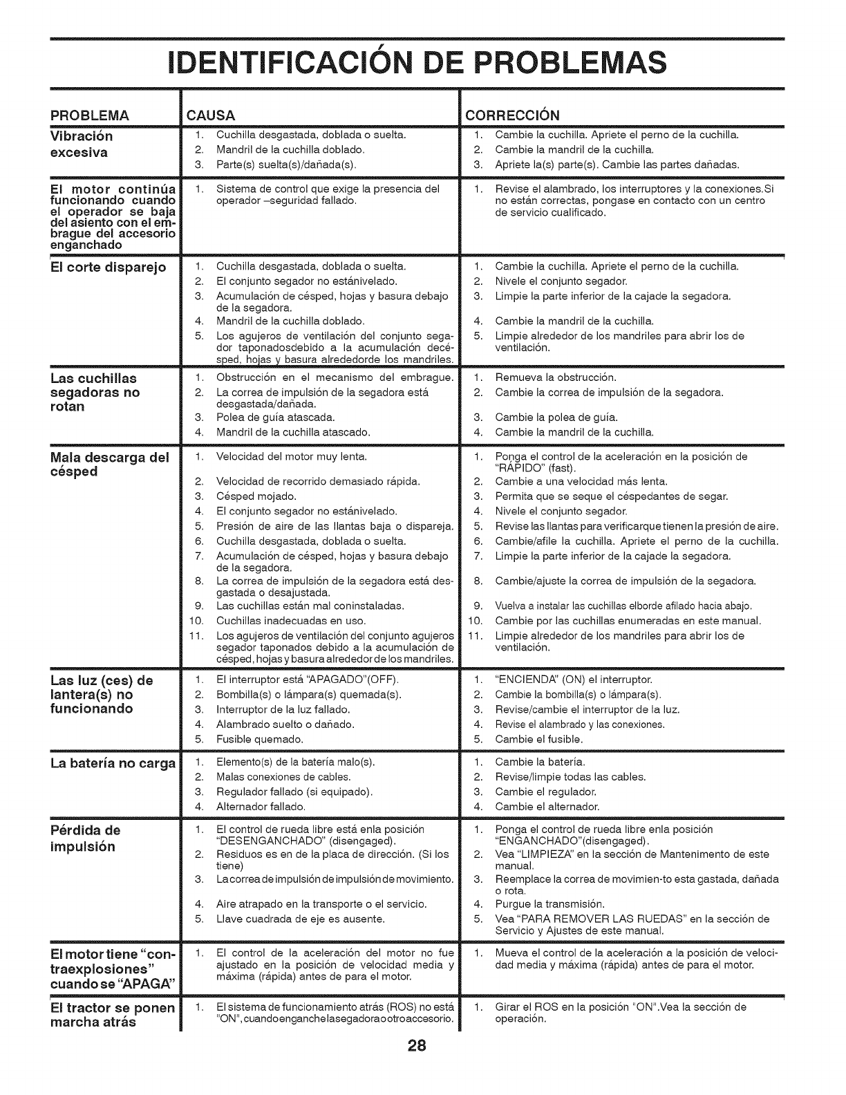
f
IDENTIFICACION DE PROBLEMAS
PROBLEMA
Vibraci6n
e×cesiva
El motor continua
funcionando cuando
el operador se baja
del asiento con eJ em-
brague del accesorio
enganchado
r
El corte disparejo
Las cuchillas
segadoras no
rotan
Mala descarga del
c_sped
Las luz (ces) de
lantera(s) no
funcionando
La bateria no carga
P_rdida de
impulsi6n
El motor tiene "con=
trae×plosiones"
cuando se "APAGA"
El tractor se ponen
rnarcha atr_s
CAUSA
1. Cuchilla desgastada, doblada o suelta.
2. Mandril de la cuchilla doblado.
3. Parte(s) suelta(s)/da_ada(s).
1. Sistema de control que exige la presencia del
operador -seguridad fallado.
1. Cuchilla desgastada, doblada o suelta.
2. El conjunto segador no est&nivelado.
3. AcumulaciSn de cesped, hojas y basura debajo
de la segadora.
4. Mandril de la cuchilla doblado.
5. Los agujeros de ventilaciSn del conjunto sega-
dor taponadosdebido a la acumulaciSn dece-
s ed_dedorde los mandriles.
1. ObstrucciSn en el mecanismo del embrague.
2. La correa de impulsiSn de la segadora est&
desgastada/daSada.
3. Polea de guia atascada.
4. Mandril de la cuchilla atascado.
1. Velocidad del motor muy lenta.
2. Velocidad de recorrido demasiado r&pida.
3. Cesped mojado.
4. El conjunto segador no est&nivelado.
5. Presi6n de aire de las Ilantas baja o dispareja.
6. Cuchilla desgastada, doblada o suelta.
7. AcumulaciSn de cesped, hojas y basura debajo
de la segadora.
8. La correa de impulsiSn de la segadora est& des-
gastada o desajustada.
9. Las cuchillas est&n mal coninstaladas.
10. Cuchillas inadecuadas en uso.
11. Los agujeros de ventilaciSn del conjunto agujeros
segador taponados debido a la acumulaciSn de
cesped, hojas y basura alrededor de los mandriles.
1. El interruptor est&'APAGADO"(OFF).
2. Bombilla(s) o I&mpara(s) quemada(s).
3. Interruptor de la luz fallado.
4. Alambrado suelto o daSado.
5. Fusible quemado.
1. Elemento(s) de la bateda malo(s).
2. Males conexiones de cables.
3. Regulador fallado (si equipado).
4. Altemador fallado.
1. El control de rueda libre est& enla posiciSn
"DESENGANCHADO" (disengaged).
2. Residuos es en de la place de direcci6n. (Si los
tiene)
3. Lacorrea de impulsiSn de impulsiSn de movimiento.
4. Aire atrapado en la transporte o el servicio.
5. Llave cuadrada de eje es ausente.
1. El control de la aceleraci6n del motor no fue
ajustado en la posiciSn de velocidad media y
m&xima (r&pida) antes de pare el motor.
1. El sistemade funcionamiento atr&s (ROS) no est&
"ON", cuandoenganchelasegadoraootroaccesorio.
CORRECCK)N
1. Cambie la cuchilla. Apriete el pemo de la cuchilla.
2. Cambie la mandril de la cuchilla.
3. Apriete la(s) parte(s). Cambie las partes daSadas.
1. Revise el alambrado, los interruptores y la conexiones.Si
no est&n correctas, pongase en contacto con un centro
de servicio cualificado.
1. Cambie la cuchilla. Apriete el pemo de la cuchilla.
2. Nivele el conjunto segador.
3. Limpie la parte inferior de la cajade la segadora.
4. Cambie la mandril de la cuchilla.
5. Limpie alrededor de los mandriles pare abrir los de
ventilaciSn.
1. Remueva la obstrucciSn.
2. Cambie la correa de impulsiSn de la segadora.
3. Cambie la polea de guia.
4. Cambie la mandril de la cuchilla.
1. Po,nga el control de la aceleraci6n en la posici6n de
"RAPIDO" (fast).
2. Cambie a una velocidad m&s lent&
3. Permita que se seque el cespedantes de segar.
4. Nivele el conjunto segador.
5. Revise las Ilantas pare verificarque tienen la presi6n de aire.
6. Cambie/afile la cuchilla. Apriete el pemo de la cuchilla.
7. Limpie la parte inferior de la cajade la segadora.
8. Cambie/ajuste la correa de impulsi6n de la segadora.
9. Vuelva a instalar las cuchillas elborde afilado hacia abajo.
10. Cambie por las cuchillas enumeradas en este manual.
11. Limpie alrededor de los mandriles para abrir los de
ventilaci6n.
1. "ENCIEND,_' (ON) el interruptor.
2. Cambie la bombilla(s) o I&mpara(s).
3. Revise/cambie el interruptor de la luz.
4. Revise el alambrado y las conexiones,
5. Cambie el fusible.
1. Cambie la bateria.
2. Revise/limpie todas las cables.
3. Cambie el regulador.
4. Cambie el alternador.
1. Ponga el control de rueda libre enla posici6n
"ENGANCHADO"(disengaged).
2. Yea "LIMPIEZA_' en la secci6n de Mantenimento de este
manual.
3. Reemplace la correa de movimien-to esta gastada, da_ada
o rota.
4. Purgue la transmisi6n.
5. Vea "PARA REMOVER LAS RUEDAS" en la secci6n de
Servicio y Ajustes de este manual.
1. Mueva el control de la aceleraci6n a la posici6n de veloci-
dad media y m&xima (r&pida) antes de para el motor.
1. Girar el ROSen la posici6n "ON".Vea la secci6n de
operaci6n.
28
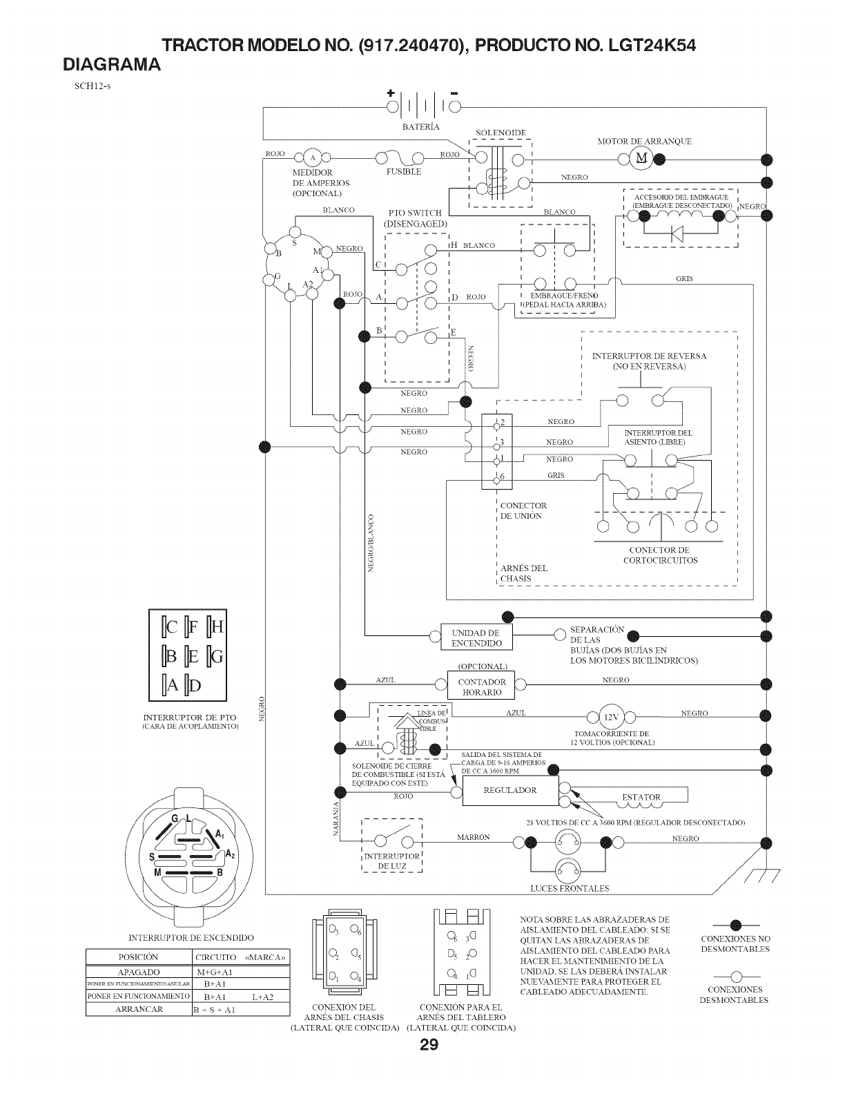
TRACTOR MODELO NO. (917.240470), PRODUCTO NO. LGT24K54
DIAGRAMA
SCH12-s
ID
INTERRUPTOR DE PTO
(CARA DE ACOPLAMIENTO)
I
I D ROJO I EMBRAGUEiFRENO
X. j_ L(P EDAL HACIAARRIBA)
1
q
q
q
<
MOTOR DE ARRANQUE
1
i
ACCESORIODEL EMBP_a_GUE I
(EMBRAGUE DESCONECTADO) ,NEGRC
GRtS
EX'TERRUPTOR DE REVERSA
(NO EN REVERSA)
[
NEGRO _._INTEENR__EL -I
NEGRO
GRtS
I
iCONEC*TOR
] DE UNION
I
I
ICONECTOR DE
]CORTOCIRCUITOS
]1ARNt_S DEL
] CHASIS
q
t
q
4
1
®
IOaDDESEPARACI6 .ENCENDIDO DE LAS
BUJIAS (DOS BUJIAS EN
LOS MOTORES BICILINDRICOS)
(OPCIONAL)
AZUL (_) CONTADORHoRARIO_ NEGRO
Ic OMBU$/
I IBLE I
TOMACORRtENTE DE
i i
AZUL I 12 VOLTIOS (OPCIONAL)
I SALIDADEL SISTEMADE
SOLEoNOIDE TDECIE(SiNR_ST,_ ;CAR_AADE 090iR6p_M......
E0_I_ADOCO_E_E)Ro,,o<_ REGULATOR_ E
I / 28 VOLTIOS DE CC A 3600 RPM (REGULADOR DESCONECTADO)
_ II I MARRON _ NEGRO/
INTERRL PTOR I
i_ _D_E_LU_Z_
LUCES FRONTALES
INTERRUPTOR DE ENCENDIDO
POSICION CIRCUITO <<MARCIA>>
APAGADO M+G+A 1
PONER FN FUNC IO_XM'_fIgNTO AN_'LAR B+._I
PONER EN FUNCIONAMIENTO B+A 1 L+A2
ARRANCAR B S + A1 ( ONEXION DEL CONEXION PARA EL
ARN1_S DEL ( HASIS ARN1_S DEL TABLERO
(LATERAL QUE COINCIDA) (LATERAL QUE COINCIDA)
29
NOTA SOBRE LAS ABP_4ZADERAS DE
AISLAMIENTO DEL CABLEADO: SI SE
QUITAN LAS ABRAZADERAS DE
AISLAMIENTO DEL CABLEADO PAIL4
HACER EL MANTENIMIENTO DE LA
U2",!IDAD. SE LAS DEBEtL& INSTALAR
:X2JEVAMENTE PAIL4 PROTEGER EL
CABLEADO ADECL ADAMENTE.
D
D
P
D
®
CONEXIONES NO
DESMONTABLES
O
( ONEXIONES
DESMONTABLES
D
P
P
D
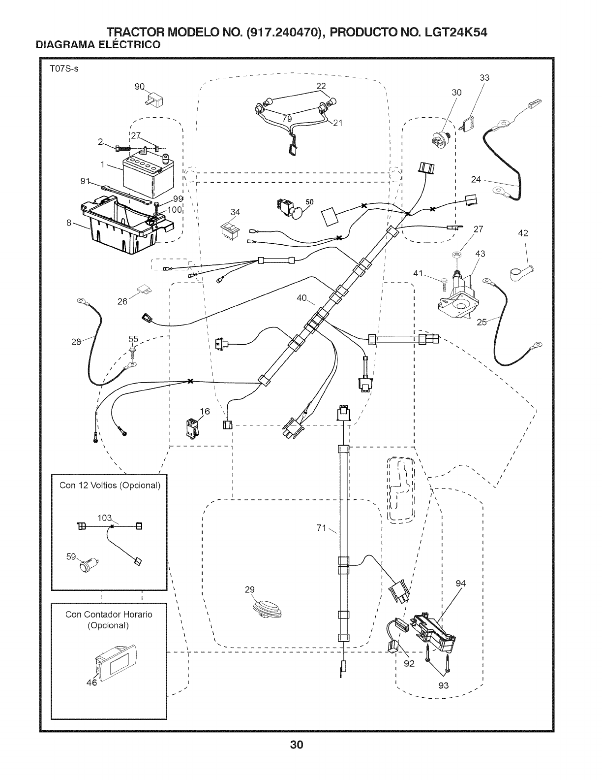
TRACTOR MODELO NO. (917.240470), PRODUCTO NO. LGT24K54
DIAGRAMA ELI_CTRICO
T07S-s 9%
/
C
\\
\
\!
\\ !
Con 12 Voltios (Opcional)
"1-13 10_. I"1
I I
t-
!
\\\
Con Contador Horario
(Opcional)
22
1
34
/
/
@>\
I
I
27
\
16 _\
71_
,t J _,'
It.___1
I _>"k&j 94
29 IX_ _ /
J. 93 .
42
\
\\
\
3O

TRACTOR MODELO NO. (917.240470), PRODUCTO NO. LGT24K54
DIAGRAMA ELECTRICO
C6DIGO PIEZA
NO. NO. DESCRIPCION
1 532 16 34-65 Baterfa
2 874 76 04-12 Perno de cabeza hexagonal de 1/4-
20 unc x 3/4
8 532 18 64-91 Caja de la baterfa
16 532 17 61-38 Interruptor corta corriente a presi6n
21 532 40 02-52 Cableado del enchufe para la luz
22 532 00 41-52 Bombilla de luz nos.1156
24 532 40 02-53 Cable
25 532 41 28-95 Cable
26 532 17 51-58 Fusible
27 873 51 04-00 Tuerca hexagonal Keps de 1/4-20 unc
28 532 14 54-91 Cable a tierra
29 532 40 15-45 Interruptor del asiento
30 532 19 33-50 Interruptor de encendido
33 532 41 19-33 Llave/cadena
34 532 11 07-12 Interruptor de luz/de restauraci6n
40 532 40 11-04 Cableado del tablero de encendido
41 817 72 04-08 Tornillo de 1/4-20 x 1/2
42 532 13 15-63 Cubierta de la terminal
43 532 19 25-07 Solenoide
46 532 40 17-63 Indicador SRVCMNDR HRMTR
50 532 17 46-51 Interruptor
55 817 06 05-12 Tornillo de 5/16-18 x 3/4
59 532 40 03-03 Enchufe, 12V
71 532 19 42-76 Cableado de encendido
79 532 17 52-42 Enchufe de cierre por torsi6n del
ensamble de la bombilla
90 532 43 53-95 Tapa de los bornes de la baterfa
91 532 19 02-70 Correa de la baterfa
92 532 19 66-15 Cableado de interruptor retroceder
93 532 19 25-40 Tornillo de 10-14 x 2.0
94 532 19 18-34 M6dulo retroceder ROS
99 817 67 04-12 Tornillo de 1/4-20 x 3/4
100 8190914-16 Arandela de 9/32 x 7/8 x calibre16
103 532 40 79-62 Cable 12V
NOTA: Las dimensiones de todos los componentes est&n expre-
sadas en putgadas americanas. 1 putgada = 25,4 mm
31
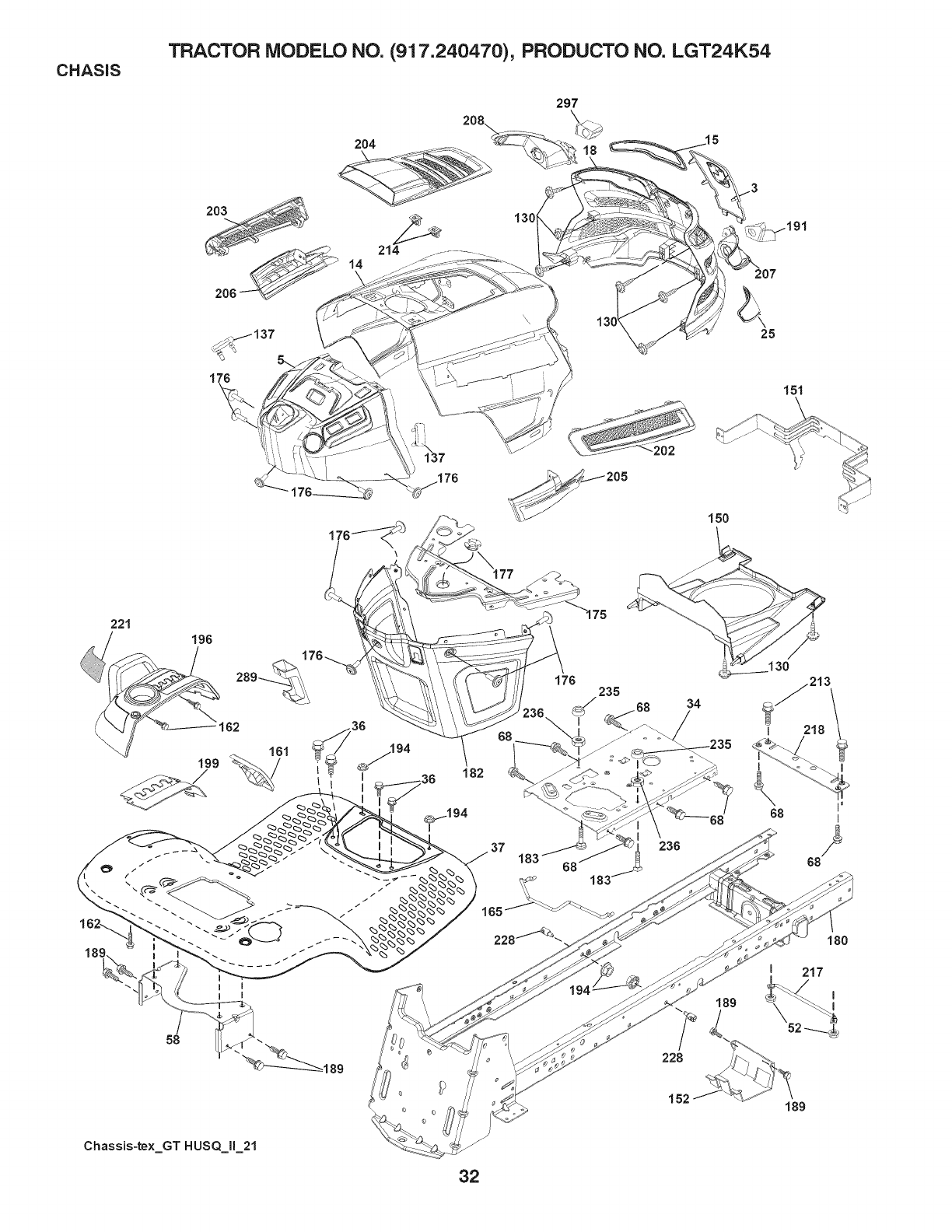
CHASIS TRACTOR MODELO NO. (917.240470), PRODUCTO NO. LGT24K54
297
130
18
207
25
151
150
221
196
162
94
I
58
176
182
37
165
235 34
228
130
I
I
68
213
218 1
I
68
152 189
Chassis-te×_GT HUSQ_II_21
32

CHASIS TRACTOR MODELO NO. (917.240470), PRODUCTO NO. LGT24K54
CODIGO PIEZA
NO. NO.
3 532 43 97-52
5 532 44 10-51
14 532 44 11-77
15 532 43 97-33
18 532 40 86-07
25 532 43 97-32
34 532 19 61-25
36 817 06 05-12
37 532 44 12-08
52 873 68-05-00
58 532 19 43-14
68 817 49 05-08
130 532 41 63-58
137 532 40 75-90
150 532 43 97-74
151 532 43 66-70
152 532 19 95-35
161 532 43 99-29
162 532 14 24-32
165 532 19 68-26
175 532 19 63-04
176 532 40 07-76
177 532 19 52-27
180 532 19 54-77
182 532 40 68-59
183 874 52 05-20
189 817 O0 05-12
191 532 43 74-55
194 873 90 05-00
C6DIGO PIEZA
DESCRIPCI6N NO. NO. DESCRIPCI6N
Logo 196 532 40 02-99
Tablero
Capota 199 532 19 82-59
Lente izquierdo de la parrilla 202 532 43 97-28
Parrilla 203 532 43 97-27
Lente derecho de la parrilla 204 532 43 57-14
Chapa Motor 205 532 43 97-30
Tornillo de 5/16-18 x 3/4 206 532 43 97-29
Guardabarros 207 532 43 97-34
Tuerca de presi6n 5/16-18 208 532 43 97-35
Soporte de Guardabarros 213 874 76 05-12
Tornillo de 5/16-18 x 1/2 214 532 19 91-45
Tornillo No.10 x 0,75 217 532 40 91-67
Cubierta Tabtero 218 532 19 63-95
Cubierta termica det conducto 221 532 19 89-09
Soporte 228 532 19 51-61
Protector contra oscurecimiento 234 532 40 47-42
Ventana de combustible 235 532 40 61-29
Tornillo de 1/4 x 1/2 236 873 93 05-00
Soporte de Tanque de Gasolina 289 532 40 35-71
Travesaho 297 532 43 74-56
Tornillo de 10-24 x 5/8 - - 532 43 18-83
Buje de direcci6n
Chasis
Tablero inferior
Perno de 5/16-18 x 1-1/4
Tornillo de 5/16-18 x 3/4
Parrilla (LD)
Tuerca de presi6n de 5/16-18
Ensamble de la consola de la plata-
forma de etevaci6n
Chapa
Salida de Ventilaci6n (LD)
Salida de Ventilaci6n (LI)
Salida de Ventilaci6n superior
Camisa de Capota (LD
Oamisa de Oapota (LI)
Biset derecho
Bisel izquierdo
Perno de 5/16-18 unc x 3/4
Cierre
Varilla giratoria
Tope
Reflector (LI)
Sujetador del travesaflo
parachoques del capota
Separador det guardabarros
Tuerca de presi6n 5/16-18 unc
Conector det crucero/tetefono
Parritla (LI)
Oonjuntos parachoques
NOTA" Las dimensiones de todos los componentes est&n expre-
sadas en pulgadas americanas. 1 putgada = 25,4 mm
33
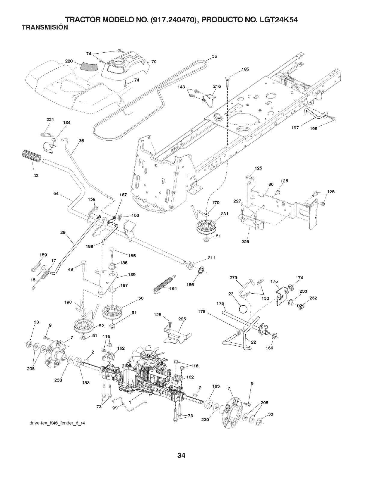
TRACTOR MODELO NO. (917.240470), PRODUCTO NO. LGT24K54
TRANSMISION
221 184
/
35
42
15
33
159
29 \
190
162
2
230 183
drive-tex_K46 fender_6_r4
143 216
197 196
227
/125
125
80
I
I183
230
34

TRACTOR MODELO NO. (917.240470), PRODUCTO NO. LGT24K54
TRANSIVlISION
CODIGO PIEZA CODIGO PIEZA
NO. NO. DESCRIPCION NO. NO. DESCRIPCION
1 532 40 62-06 Transeje, TUFFTORQ K46 AW 174 532 19 72-89 Tuerca
(Piezas internas no disponibte) 175 532 40 62-08 Ensambte det eje
2 532 18 62-11 Uave 176 532 19 62-14 Brazo
7 532 19 98-44 Ensambte del cubo trasero 22" TX 178 532 19 74-56 Resorte
GT .06 183 532 40 04-24 Separador
9 532 14 00-80 Perno 184 532 44 14-55 Manija del freno de mano
15 819 13 13-16 Arandela 13/32 x 13/16 x 16 Ga. 185 872 11 06-22 Perno 3/8-16 x 2-3/4 Gr. 5
17 532 41 36-78 Resorte de freno 186 532 19 43-21 Espaciador de retenci6n
22 532 19 73-29 Varilta 187 819 13 32-10 Arandela
23 532 14 08-45 Perilla 188 532 19 43-23 Mecanismo de desplazamiento de la
29 532 40 38-06 Varilla det freno varilla de mando del embrague
33 812 00 00-01 Aro E 189 532 19 43-17 Palanca acodada det mecanismo de
35 532 43 54-86 Varilla det freno de mano desplazamiento
42 532 12 48-72 Cubierta del pedal 190 532 19 43-18 Sujetador de la palanca acodada
49 87211 06-14 Perno det mecanismo de desptazamiento
50 532 19 43-27 Polea Ioca plana 196 817 00 06-16 Tornillo 3/8-16 x 1
51 873 90 06-00 Tuerca de presi6n de 3/8-16 197 532 19 97-69 Mecanismo de desptazamiento
52 532 19 43-26 Polea Ioca con ranura en V con 205 532 12 17-48 Arandeta
un desplazamiento de 910" (23 m) 211 532 19 62-12 Buje
56 532 13 09-69 Correa trapezoidal de la transmisi6n 216 532 19 61-31 Soporte
64 532 19 62-00 Ensamble del eje Control det pedal 220 532 19 89-08 Reflector derecho
de freno 221 532 40 31-87 Abrazadera de retenci6n det resorte
70 532 43 96-60 Ensambte de la consola de la manija
73 874 49 05-60 Pemo 5/16-18 3.75 225 532 40 33-19 Sujetador de la correa
74 532 14 24-32 Tornitlo 1/4 x 1/2 226 532 40 08-31 Soporte
80 532 44 06-19 Correa de torsi6n 227 817 49 05-12 Tomitto 5/16-18 x 3/4
99 532 41 57-43 Varilla de desviaci6n 230 532 18 89-67 Arandeta
116 873 90 05-00 Tuerca 5/16-18 231 532 40 72-87 Polea Ioca con ranura en V con un
125 817 00 05-12 Tornillo 5/16-18 x 3/4 desptazamiento de 1.688"
143 817 49 05-08 Tornitlo 5/16-18 x 1/2 232 874 78-07-16 Perno 7/16-14 x 1 Gr. 5
153 532 12 47-88 Reten del resorte 233 532 40 52-96 Arandela
159 876 02 04-12 Pasador de chaveta de 1/8 x 3/4 279 532 40 62-07 Acoptamiento
160 532 16 94-84 Abrazadera de retenci6n
161 532 10 57-09 Resorte de retorno del embrague
162 532 19 57-85 Separador de transeje 18 y 22
166 532 42 91-64 Tuerca NOTA: Las dimensiones de todos los componentes esta.n expre-
167 532 40 52-57 Pestillo del freno de mano sadas en putgadas americanas. 1 putgada = 25,4 mm
170 532 41 34-30 Sujetador de la correa central
35
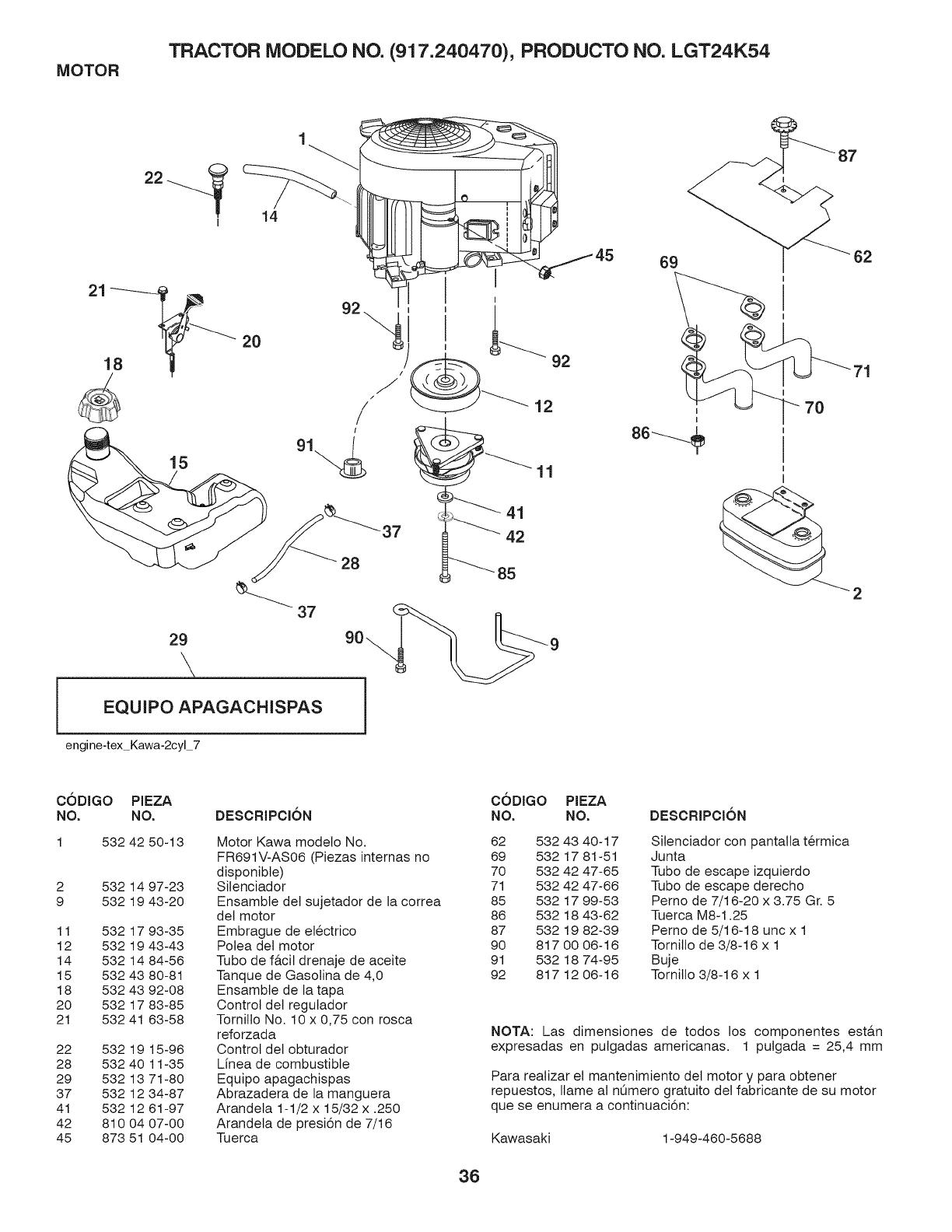
MOTOR TRACTOR MODELO NO. (917.240470), PRODUCTO NO. LGT24K54
{
14
15
)
/
J
/
/
29
EQUIPO APAGACHISPAS
engine-tex Kawa-2cyl 7
92
12
69
11
42
5 ,
2
C6DIGO PIEZA
NO. NO. DESCRIPCI6N
1 532 42 50-13
2 532 14 97-23
9 532 19 43-20
11 532 17 93-35
12 532 19 43-43
14 532 14 84-56
15 532 43 80-81
18 532 43 92-08
20 532 17 83-85
21 532 41 63-58
22 532 19 15-96
28 532 40 11-35
29 532 13 71-80
37 532 12 34-87
41 532 12 61-97
42 810 04 07-00
45 873 51 04-00
Motor Kawa modelo No.
FR691V-AS06 (Piezas internas no
disponibte)
Silenciador
Ensambte det sujetador de la correa
det motor
Embrague de etectrico
Potea det motor
Tubo de f&cit drenaje de aceite
Tanque de Gasolina de 4,0
Ensamble de la tapa
Control det regutador
Tornillo No. 10 x 0,75 con rosca
reforzada
Control del obturador
Lfnea de combustible
Equipo apagachispas
Abrazadera de la manguera
Arandela 1-1/2 x 15/32 x .250
Arandela de presi6n de 7/16
Tuerca
C6DIGO PIEZA
NO. NO. DESCRIPCI6N
62 532 43 40-17 Silenciador con pantalla t@mica
69 532 17 81-51 Junta
70 532 42 47-65 Tubo de escape izquierdo
71 532 42 47-66 Tubo de escape derecho
85 532 17 99-53 Perno de 7/16-20 x 3.75 Gr. 5
86 532 18 43-62 Tuerca M8-1.25
87 532 19 82-39 Perno de 5/16-18 unc x 1
90 8170006-16 Tornillo de 3/8-16 x 1
91 532 18 74-95 Buje
92 817 12 06-16 Tornillo 3/8-16 x 1
NOTA: Las dimensiones de todos los componentes est&n
expresadas en putgadas americanas. 1 putgada = 25,4 mm
Para realizar el mantenimiento det motor y para obtener
repuestos, Ilame al nOmero gratuito del fabricante de su motor
que se enumera a continuaci6n:
Kawasaki 1-949-460-5688
36

TRACTOR MODELO NO. (917.240470), PRODUCTO NO. LGT24K54
ENSAMBLE DE LA DIRECCION
19 I 60
U 57 63
67 _66
steering-tex LEGND2 18 rl
62
CODIGO PIEZA
NO. NO.
1 532 43 99-97
2 532 19 59-68
4 532 40 30-89
5 532 40 30-90
6 532 12 49-31
7 532 12 17-48
8 812 00 00-29
9 532 12 12-32
13 532 12 17-49
14 810 04 06-00
15 873 54 06-00
16 532 40 82-19
19 532 19 47-29
21 532 18 67-37
22 532 42 05-37
26 532 43 97-43
28 817 00 06-12
35 532 19 47-32
45 8191838-12
51 873 94 08-00
53 532 18 89-67
DESCRIPCION
Votante de direcci6n
Ensamble del eje delantero
Ensambte del husillo izquierdo
Ensamble del husillo derecho
Pista del rodamiento para reforzar et
imputso
Arandela de 25/32 x 1-5/8 calibre 16
Abrazadera det aro No. T5304-75
Tapa det husillo
Arandela de 25/32 x 1-1/4 calibre 16
Arandela de presi6n de 3/8
Tuerca de 3/8-24 unf
Eje de direcci6n
Placa de direcci6n
Adaptador del votante de direcci6n
Direcci6n apoyo inferior
Inserto det volante de direcci6n
Tornillo de 3/8-16 x 3/4
Engranaje det sector de la ptaca
Arandeta de 9/16 IDx 2-3/8 x calibre 12
Contratuerca hexagonal de seguridad
de 1/2-20 unf
Arandeta .793 x 1.637 x .060
CODIGO PIEZA
NO. NO.
57 532 19 72-46
58 532 19 47-47
59 532 19 47-48
60 873 97 10-00
61 532 19 47-40
62 532 19 47-41
63 817 00 05-12
64 532 19 98-49
66 871 02 07-48
67 532 19 47-37
68 873 90 07-00
69 532 19 91-62
70 532 19 61-97
DESCRIPCION
Tope superior det soporte
Perno de tope det sector det pivote
CFM
Arandeta de empuje det sector de
direcci6n
Tuerca de 5/8-11
Barra de acoptamiento izquierda
Barra de acoptamiento derecha
Tornitlo de 5/16-18 x 3/4
Abrazadera de retenci6n det resorte
de la direcci6n
Perno de cabeza hexagonal con
brida acanalada de 7/16-14 x 3
Buje PM det eje detantero
Tuerca de 7/16-14 grado 5
Arandeta de 1,5 x 0,505 x 0,118
Soporte de la ptataforma detantera
NOTA: Las dimensiones de todos los componentes est&n expre-
sadas en putgadas americanas. 1 putgada = 25,4 mm
37
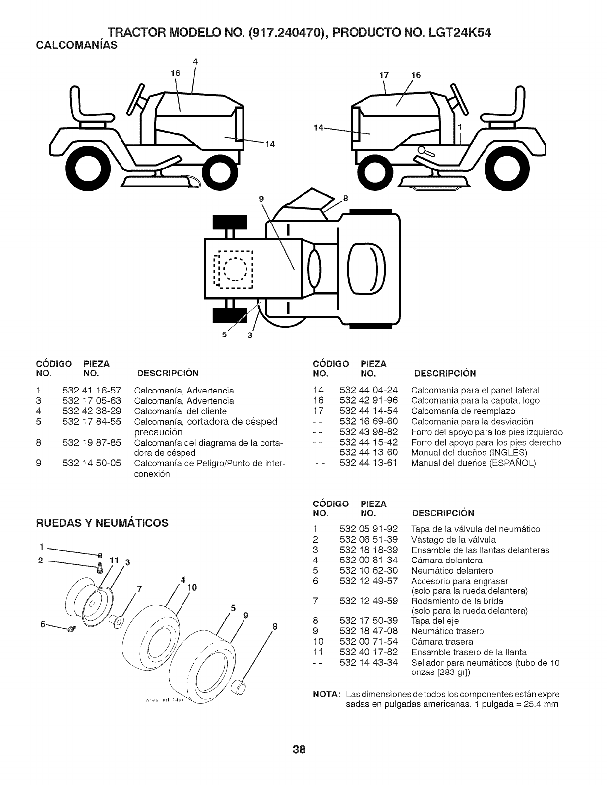
TRACTOR MODELO NO. (917.240470), PRODUCTO NO. LGT24K54
CALCOMANJAS
4
16 17 16
5 3
C6DIGO PIEZA C6DIGO
NO. NO. DESCRIPCl6N NO.
1 532 41 18-57
3 532 17 05-63
4 532 42 38-29
5 532 17 84-55
8 532 19 87-85
9 532 14 50-05
Calcomania, Advertencia 14 532
Calcomania, Advertencia 18 532
Calcomania del ctiente 17 532
Calcomania, cortadora de c6sped - - 532
precaucJ6n - - 532
Calcomania del diagrama de la corta- - - 532
dora de cesped - - 532
Calcomania de Petigro/Punto de inter- - - 532
conexi6n
PIEZA
NO.
44 04-24
42 91-98
44 14-54
18 89-80
43 98-82
44 15-42
44 13-80
44 13-81
DESCRIPCI6N
Calcomania para el panel lateral
Calcomania para la capota, logo
Calcomania de reemplazo
Catcomania para la desviaci6n
Forro det apoyo para los pies izquierdo
Forro del apoyo para los pies derecho
Manual del duehos (INGLE_S)
Manual det due_os (ESPA_4OL)
RUEDASY NEUMATICOS
1
2 3
wheel art
410
9
C6DIGO PIEZA
NO. NO.
1 532 05 91-92
2 532 08 51-39
3 532 18 18-39
4 532 00 81-34
5 532 10 82-30
8 532 12 49-57
7 532 12 49-59
8 532 17 50-39
9 532 18 47-08
10 532 00 71-54
11 532 40 17-82
- - 532 14 43-34
DESCRIPCI6N
Tapa de la v&tvuta det neum&tico
V&stago de la v&lvuta
Ensambte de las Ilantas detanteras
C&mara detantera
Neum&tico detantero
Accesorio para engrasar
(solo para la rueda detantera)
Rodamiento de la brida
(solo para la rueda detantera)
Tapa det eje
Neum&tico trasero
C&mara trasera
Ensamble trasero de la Ilanta
Seltador para neum&ticos (tubo de 10
onzas [283 gr])
NOTA: Las dimensJones detodos los componentes est&n expre-
sadas en putgadas americanas. 1 putgada = 25,4 mm
38
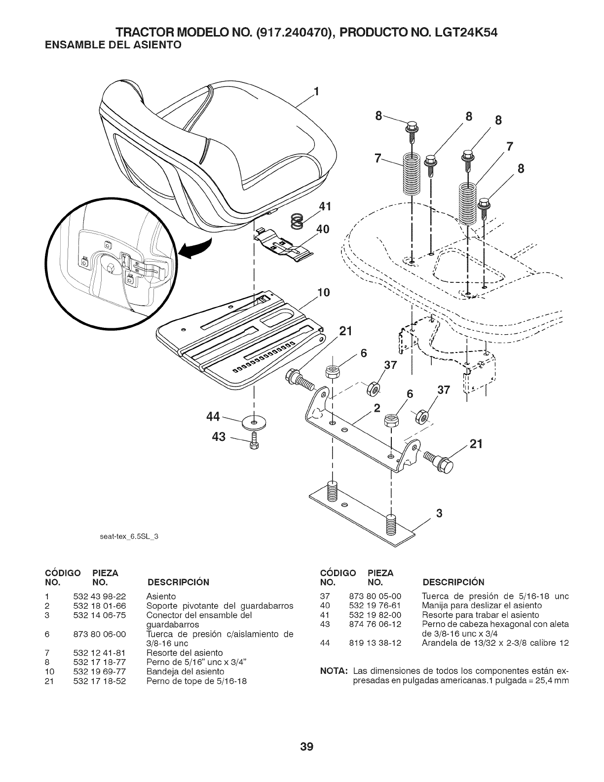
TRACTOR MODELO NO. (917.240470), PRODUCTO NO. LGT24K54
ENSAMBLE DEL ASIENTO
8 8
41
7
8
I
seat-tex 6.5SL 3
3
C6DIGO PIEZA
NO. NO.
1 532 43 98-22
2 532 18 01-66
3 532 14 06-75
6 873 80 06-00
7 532 12 41-81
8 532 17 18-77
10 532 19 69-77
21 532 17 18-52
DESCRIPCION
Asiento
Soporte pivotante del guardabarros
Conector det ensambte det
guardabarros
Tuerca de presi6n c/aistamiento de
3/8-16 unc
Resorte det asiento
Perno de 5/16" unc x 3/4"
Bandeja det asiento
Perno de tope de 5/16-18
C6DIGO PIEZA
NO. NO.
37 873 80 05-00
40 532 19 76-61
41 532 19 82-00
43 874 76 06-12
44 819 13 38-12
DESCRIPCION
Tuerca de presi6n de 5/16-18 unc
Manija para destizar et asiento
Resorte para trabar et asiento
Perno de cabeza hexagonal con aleta
de 3/8-16 unc x 3/4
Arandeta de 13/32 x 2-3/8 calibre 12
NOTA" Las dimensiones de todos los componentes est&n ex-
presadas en putgadas americanas.1 putgada = 25,4 mm
39
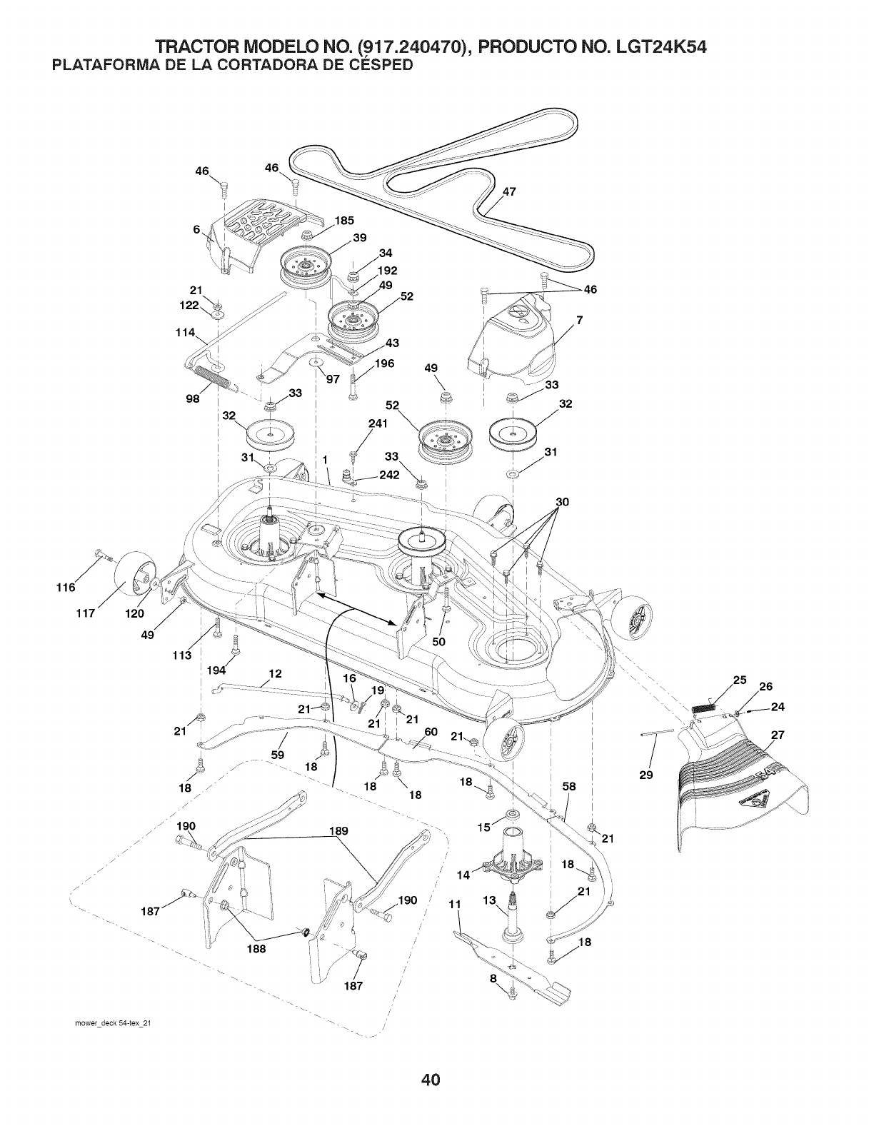
TRACTOR MODELO NO. (917.240470), PRODUCTO NO. LGT24K54
PLATAFORIVIA DE LA CORTADORA DE CESPED
46 46\
6,
185
39
i33
43
116
117 120
49 '3
113 ,il 9 12
I
I
mower deck 54-tex 21
18
14
\
29
25 26
27
4O

TRACTOR MODELO NO. (917.240470), PRODUCTO NO. LGT24K54
PLATAFORIVlA DE LA CORTADORA DE CESPED
C6DIGO PIEZA CODIGO PIEZA
NO. NO. DESCRIPCION NO. NO. DESCRIPCION
1 532 44 15-47 Carcasa de la cortadora de cesped
6 532 19 60-66 Cubierta derecha det mandril 58 532 18 73-42
7 532 19 71-81 Cubierta izquierda del mandril 59 532 18 73-44
8 532 19 30-03 Perno/arandeta det ensamble de 60 532 18 76-07
7/16-20 unf 97 532 17 85-15
11 532 18 72-56 Cuchilla de la cortadora de cesped 98 532 19 61-05
- - 532 18 72-55 Cuchitta, mantillo 113 872 11 05-08
12 532 40 48-51 Barra 114 532 18 75-56
13 532 18 72-91 Ensambte det eje del mandril 116 532 19 34-06
14 532 18 72-81 Carcasa det mandril 117 532 17 48-73
16 819 13 13-12 Arandela 120 819 13 20-12
15 532 11 04-85 Rodamiento de bolas det mandril 122 532 18 75-57
18 872 14 05-05 Perno 185 873 90 07-00
19 532 19 42-08 AIfiler 187 532 19 51-61
21 873 68 05-00 Tuerca 188 873 90 05-00
24 532 10 53-04 Tapa de la manga 189 532 19 51-85
25 532 17 81-02 Resorte de torsi6n det deflector 190 532 19 65-39
26 532 11 04-52 Tuerca de presi6n 192 532 19 84-68
27 532 18 89-38 Protector det deflector 194 874 49 07-36
29 532 13 14-91 Varilla de ta bisagra 196 872 14 06-20
30 532 17 39-84 Tornitlo con cabeza de arandeta 241 532 15 29-27
31 532 18 76-90 Arandeta del separador 242 532 41 55-98
32 532 15 35-35 Polea del mandril - - 532 41 64-05
33 532 40 02-34 Tuerca de seguridad con brida - - 532 18 72-92
34 873 68 06-00 Tuerca
39 532 19 73-80 Polea Ioca
43 532 19 60-65 Brazo de la potea
46 532 13 77-29 Espaciador de retenci6n
47 532 19 61-03 Tornillo hexagonal con arandeta de - - 532 43 29-07
3/8-16 x 1
49 873 90 06-00 Tuerca 3/8-16 unc
50 872 11 06-16 Brazoizquierdodetfrenodetacortadora
de cesped
52 532 19 73-79 Brazo det freno de la cortadora de
cesped
Varillaje det freno
Manija det cable de embrague
Correa trapezoidal
Perno
Resorte
Perno
Barra
Perno de tope
Catibrador de la rueda
Arandeta
Buje
Tuerca 7/16-14 Gr. 5
Sujetador det travesaflo
Tuerca de presi6n hexagonal con brida
Barra
Perno de tope
Sujetador de la correa
Perno 7/16-24
Perno
Tornillo
Puerto de lavado de la cubierta
Accesorio det conexi6n
Ensambte del Mandril (solo incluye la
carcasa, et ensamble det eje y et ro-
damiento; no inctuye la polea/tuerca/
arandela ni los pernos/arandetas de
la cuchitta)
Reemplazo de la cortadora de
cesped, compteta
NOTA: Las dimensiones de todos los componentes est&n expre-
sadas en putgadas americanas. 1 putgada = 25,4 mm
41
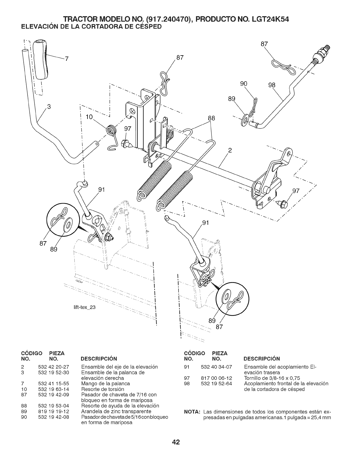
TRACTOR MODELO NO. (917.240470), PRODUCTO NO. LGT24K54
ELEVACION DE LA CORTADORA DE CESPED
87
87 89
88
2
/
91
/
/
97 /
/
/
/
/
CODIGO PIEZA
NO. NO.
2 532 42 20-27
3 532 19 52-30
7 532 41 15-55
10 532 19 63-14
87 532 19 42-09
88 532 19 53-04
89 819 19 19-12
90 532 19 42-08
DESCRIPCl6N
Ensambte del eje de la elevaci6n
Ensamble de la palanca de
elevaci6n derecha
Mango de la palanca
Resorte de torsi6n
Pasador de chaveta de 7/16 con
bloqueo en forma de mariposa
Resorte de ayuda de la etevaci6n
Arandela de zinc transparente
Pasador de chaveta de5/16 con btoqueo
en forma de mariposa
CODIGO PIEZA
NO. NO.
91 532 40 34-07
97 817 00 06-12
98 532 19 52-64
DESCRIPCION
Ensamble del acoptamiento Et-
evaci6n trasera
Tornillo de 3/8-16 x 0,75
Acoplamiento frontal de ta elevaci6n
de la cortadora de cesped
NOTA: Las dimensiones de todos los componentes est&n ex-
presadas en putgadas americanas. 1 putgada = 25,4 mm
42

TRACTOR - - MODELO NO. (917.240470), PRODUCTO NO. LGT24K54
TUFFTORQ TRANSEJE MODELO NO. K46AW
MODEL K46AW
7A646084090
87
LAS PIEZAS REALES PU-
EDENTENERUNASPECTO @ 86
DISTINTO DEL MOSTRADO i 84
85
_2_ 34
101
107
102
108
96 97
72
I
102
l0
15
72
I
C6DIGO PIEZA
NO. NO.
7 414395
8 414396
9 414397
10 415923
13 414398
15 414399
16 414400
19 414401
20 414402
33 414403
34 414404
35 414405
58 414406
72 414407
76 414408
78 414409
80 414410
81 414411
82 414412
83 414413
84 414414
DESCRIPCI6N
V,a,LVULA DE VENTILACION 15
IM,&N
SOPORTE DEL IM,a,N
KIT EJE/COJINETE DE BOMBA
PALANCA DE DERIVACI6N
TAPA HERME_TICA 30
ANILLO Eb&,STICO C 35
JUNTA TORICA 1A P10A
JUNTA 153507
EJE DE BOMBA (ESTANDAR)
ANILLO E 15
COJINETE 6202C3
PASADOR EL,&STICO 6 * 40
JUNTA 19 * 32 * 8
PALANCA DE FRENO
MUELLE DE RETORNO DE
FRENO
PASADOR DE MUELLE 5 * 32
JUNTA TORICA IA P12
PASADOR DE MUELLE 4 * 16
COLLAR[N CERVICAL
POLEA L
C6DIGO PIEZA
NO. NO.
85 414415
86 414416
87 414417
90 414418
91 414419
95 415850
96 414420
97 414421
101 414216
102 414423
103 414424
105 414425
106 414426
107 414427
108 414428
109 414429
DESCRIPCI6N
VENTILADOR, NEGRO
ARANDELA ONDULADA
ANILLO EL/_STICO
PASADOR DE MUELLE 3.0A*
20
JUNTA DE ACEITE 16 * 22 * 03
PASADOR DE MUELLE 3.0A*
16
PASADOR EL/kSTICO 3,5 * 40
PALANCA DE CONTROL
TUERCA DE BLOQUEO 10
ARANDELA 10 * 40 * 4
MUELLE
ESPARRAGO 10 * 60
TAPA HERME_TICA 18
ARANDELA 10 * 36 * 2,8
COLLAR[N 10"20"17
KIT DE PLACA DE FRICCION
NOTA" Las dimensiones de todos los componentes estfin ex-
presadas en putgadas americanas.1 putgada = 25,4 mm
43

TRACTOR -- MODELO NO. (917.240470) PRODUCTO NO. LGT24K54
KAWASAK! MOTOR- MODELO NO. FR691V, TIPO NO. AS06
ClLINDRO/CARTER
E0110-A652A
130A
--49120
92153_ 130 1109914091 130B
11061
11061A
32155
_214
_ .................13272
_16126
92o49B
1
-_
92o43..................o_32164
°20434 B2o43)04
3216_ _ 13oA
49015_
92049A_
11022A
92153A-----_
92104_ 130B
11061
130A
11008
1192i4_
92043
PISTON/CIGOEI_AL
92033_
130021_{_ }
'_92151
I__
VALVULA/AFIBOL DE LEVAS
E01 30-A1 76A
-_6022':06°
12016 12011
130 1200499078
12006 13116 %_
130 49078
I12032
I_112__ _ 9116
12116_ _3t2 _t2009 _O_62140
11053 _12011
/_92200 _3 _2
_2153 11955
_62152 _ _----62200 _Z_---62_00_
i___021,3o---.06,
_12016 _92033
_92200B
_2t52
LUBRICACION=EQUiPO
E0120-A407A
16031
E0140-A474A
_--_92156A
.....__-o21,,
O_21_9
656_
92000A_
43065A
670
44
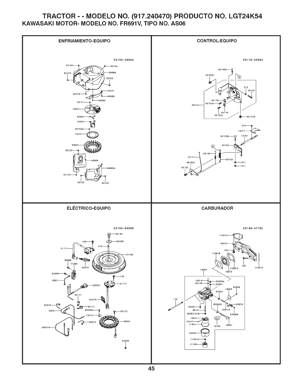
TRACTOR - - MODELO NO. (917.240470) PRODUCTO NO. LGT24K54
KAWASAK! MOTOR- MODELO NO. FR691V, TIPO NO. AS06
ENFRIAMIENTO-EQUIPO
92153
92t51_
E01 50-A996A
_i 2153
59066
3
3070
92009
--92009
t4.037_
92026_
23062_
59041
921_3_
9089
92t53_ 92_53
EL#CTRICO-EQUIPO
CONTROL=EQUIPO
E01 70-A686A
CARBURADOR
E0160-1400B
110610_
92154
2_o3_ ,d" II _2oo9._ ,,i____2_72
92i66
E0180-A778E
1
11061D
45
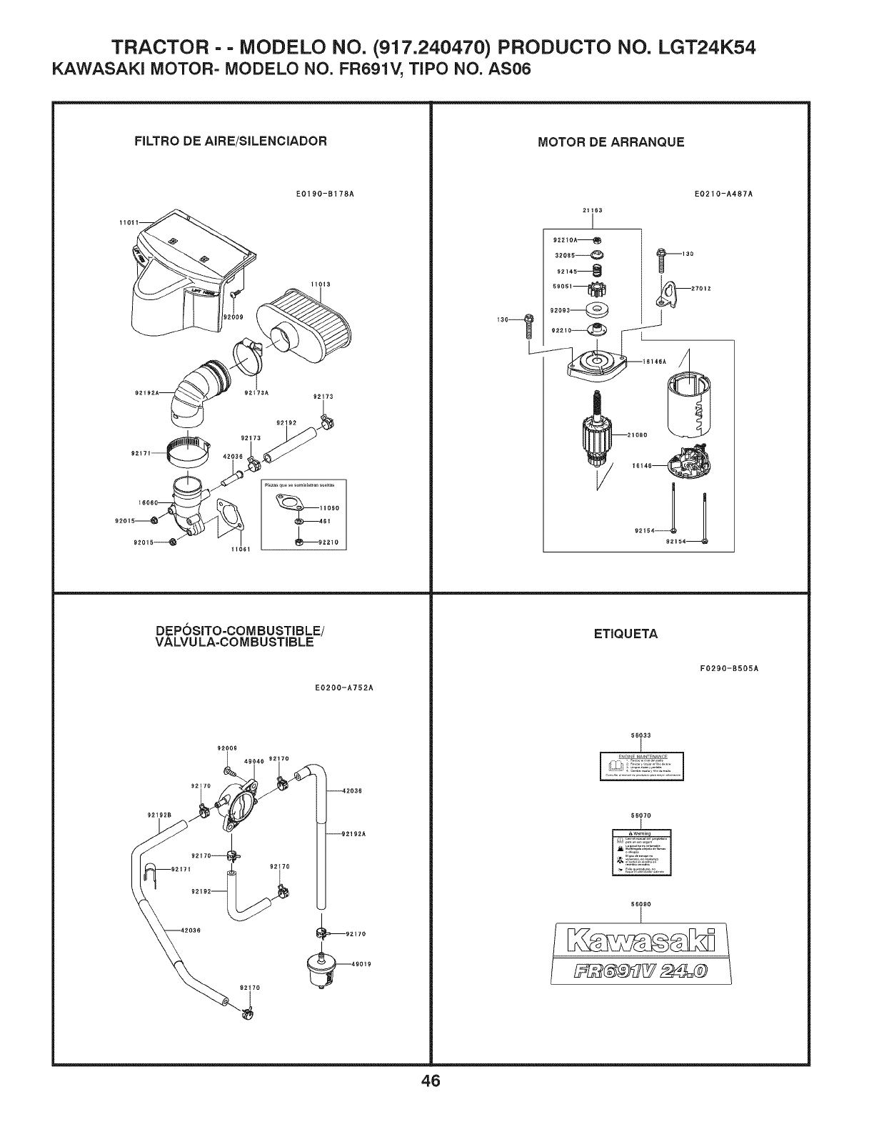
TRACTOR -- MODELO NO. (917.240470) PRODUCTO NO. LGT24K54
KAWASAK! MOTOR- MODELO NO. FR691V, TIPO NO. AS06
E0200-A752A
FILTRO DE AIRE/SILENCIADOR
DEPOSiTO-COMBUSTIBLE/
VALVU LA=COMBUSTIBLE
MOTOR DE ARRANQUE
EO210-A487A
21163
!
922tOA_
32o85@ _3o
92145 4
2t080
16146_
92'54-_92154_
ETIQUETA
56O33
J
]. r,
56070
F0290-B505A
56080
I
46
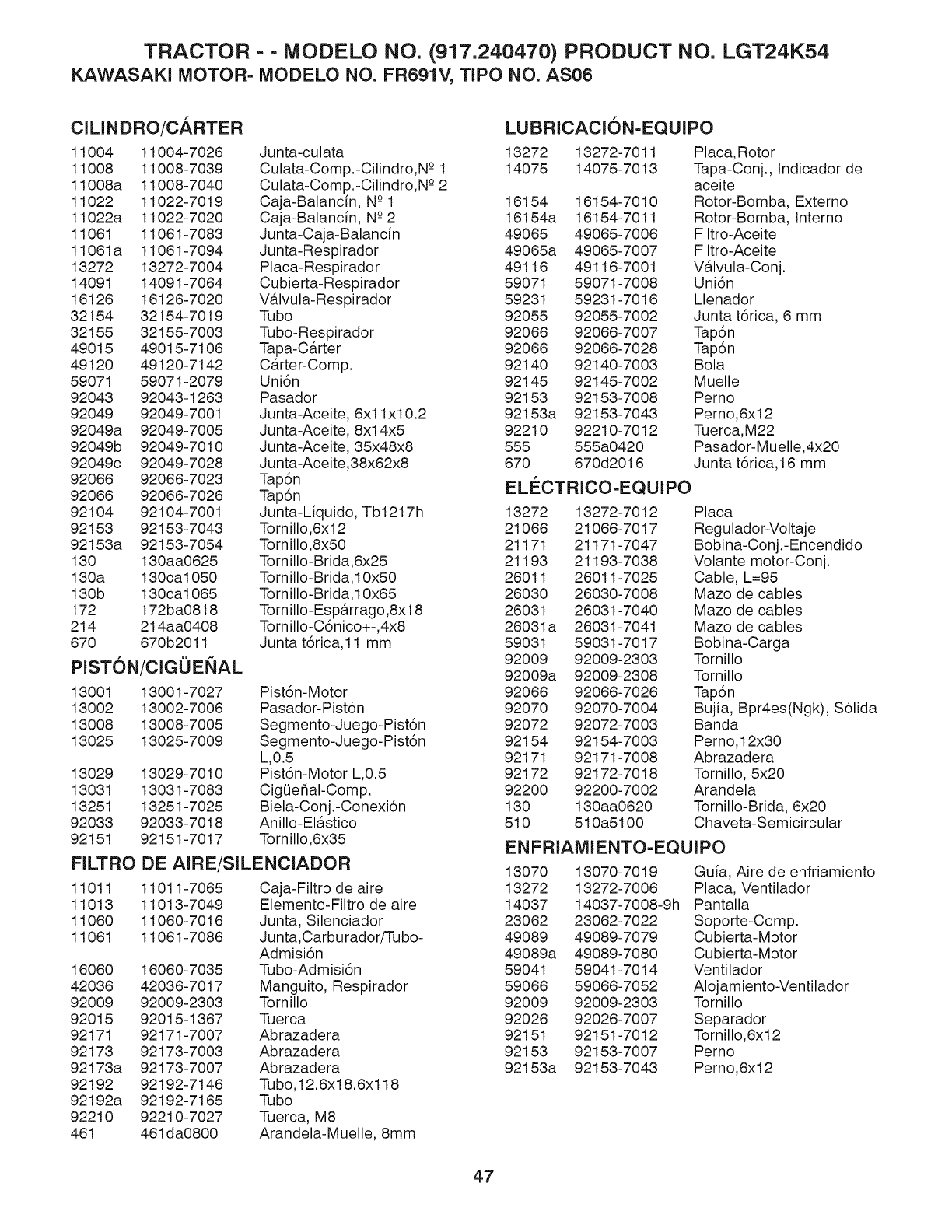
TRACTOR - - MODELO NO. (917.240470) PRODUCT NO. LGT24K54
KAWASAKI MOTOR= MODELO NO. FR691V, TIPO NO. AS06
ClLINDRO/CARTER
11004 11004-7026
11008 11008-7039
11008a 11008-7040
11022 11022-7019
11022a 11022-7020
11061 11061-7083
11061a 11061-7094
13272 13272-7004
14091 14091-7064
16126 16126-7020
32154 32154-7019
32155 32155-7003
49015 49015-7106
49120 49120-7142
59071 59071-2079
92043 92043-1263
92049 92049-7001
92049a 92049-7005
92049b 92049-7010
92049c 92049-7028
92066 92066-7023
92066 92066-7026
92104 92104-7001
92153 92153-7043
92153a 92153-7054
130 130aa0625
130a 130ca1050
130b 130ca1065
172 172ba0818
214 214aa0408
670 670b2011
PISTON/ClGOENAL
LUBRICACION=EQUIPO
Junta-culata 13272
Culata-Comp.-Cilindro,N -°1 14075
Culata-Comp.-Cilindro,N -°2
Caja-Balancfn, N-°1 16154
Caja-Balancfn, N-°2 16154a
Junta-Caja-Balancfn 49065
Junta-Respirador 49065a
Placa-Respirador 49116
Cubierta-Respirador 59071
V&lvula-Respirador 59231
Tubo 92055
Tubo-Respirador 92066
Tapa-C&rter 92066
C&rter-Comp. 92140
Uni6n 92145
Pasador 92153
Junta-Aceite, 6xl lx10.2 92153a
Junta-Aceite, 8xl 4x5 92210
Junta-Aceite, 35x48x8 555
Junta-Aceite,38x62x8 670
Tap6n
Tap6n
Junta-Liquido, Tb1217h
Tornillo,6x12
Tornillo,8x50
Tornillo-Bdda,6x25
Tornillo-Bdda,l 0x50
Tornillo-Bdda,10x65
Tornillo-Esp&rrago,8x18
Tornillo-C6nico+-,4x8
Junta t6nca,11 mm
13001 13001-7027 Pist6n-Motor
13002 13002-7006 Pasador-PistSn
13008 13008-7005 Segmento-Juego-Pist6n
13025 13025-7009 Segmento-Juego-Pist6n
L,0.5
13029 13029-7010 Pist6n-Motor L,0.5
13031 13031-7083 CigQeSaI-Comp.
13251 13251-7025 Biela-Conj.-Conexi6n
92033 92033-7018 Anillo-El&stico
92151 92151-7017 Tornillo,6x35
FILTRO DE AIRE/SILENCIADOR
11011 11011-7065 Caja-Filtro de aire
11013 11013-7049 Elemento-Filtro de aire
11060 11060-7016 Junta, Silenciador
11061 11061-7086 Ju nta,Carbu rador/Tu bo-
Admisi6n
16060 16060-7035 Tubo-Adm isi6 n
42036 42036-7017 Manguito, Respirador
92009 92009-2303 Tornillo
92015 92015-1367 Tuerca
92171 92171-7007 Ab razadera
92173 92173-7003 Ab razadera
92173a 92173-7007 Abrazadera
92192 92192-7146 Tubo,12.6x18.6x118
92192a 92192-7165 Tubo
92210 92210-7027 Tuerca, M8
461 461da0800 Arandela-Muelle, 8mm
13272-7011
14075-7013
16154-7010
16154-7011
49065-7006
49065-7007
49116-7001
59071-7008
59231-7016
92055-7002
92066-7007
92066-7028
92140-7003
92145-7002
92153-7008
92153-7043
92210-7012
555a0420
670d2016
ELECTRICO=EQUIPO
Placa,Rotor
Tapa-Oonj., Indicador de
aceite
Rotor-Bomba, Externo
Rotor-Bomba, Interno
Filtro-Aceite
Filtro-Aceite
VAIvula-Oonj.
Uni6n
Llenador
Junta t6rica, 6 mm
Tap6n
Tap6n
Bola
Muelle
Perno
Perno,6x12
Tuerca,M22
Pasador-Muelle,4x20
Junta t6rica,16 mm
13272 13272-7012 Placa
21066 21066-7017 Reg ulado r-Voltaje
21171 21171-7047 Bobi na-Conj.- Encendido
21193 21193-7038 Volante motor-Conj.
26011 26011-7025 Cable, L=95
26030 26030-7008 Mazo de cables
26031 26031-7040 Mazo de cables
26031a 26031-7041 Mazo de cables
59031 59031-7017 Bobi na-Carga
92009 92009-2303 Tornillo
92009a 92009-2308 Tornillo
92066 92066-7026 Tap6n
92070 92070-7004 Bujia, Bpr4es(Ngk), S61ida
92072 92072-7003 Banda
92154 92154-7003 Perno, 12x30
92171 92171-7008 Abrazadera
92172 92172-7018 Tornillo, 5x20
92200 92200-7002 Arandela
130 130aa0620 Tornillo-Brida, 6x20
510 510a5100 Chaveta-Semicircular
ENFRIAMIENTO=EQUIPO
13070 13070-7019 Guia, Aire de enfriamiento
13272 13272-7006 Placa, Ventilador
14037 14037-7008-9h Pantalla
23062 23062-7022 Soporte-Comp.
49089 49089-7079 Cubierta-Motor
49089a 49089-7080 Cubierta-Motor
59041 59041-7014 Ventilador
59066 59066-7052 Alojamiento-Ventilador
92009 92009-2303 Tornillo
92026 92026-7007 Separador
92151 92151-7012 Tornillo,6x12
92153 92153-7007 Perno
92153a 92153-7043 Perno,6x12
47
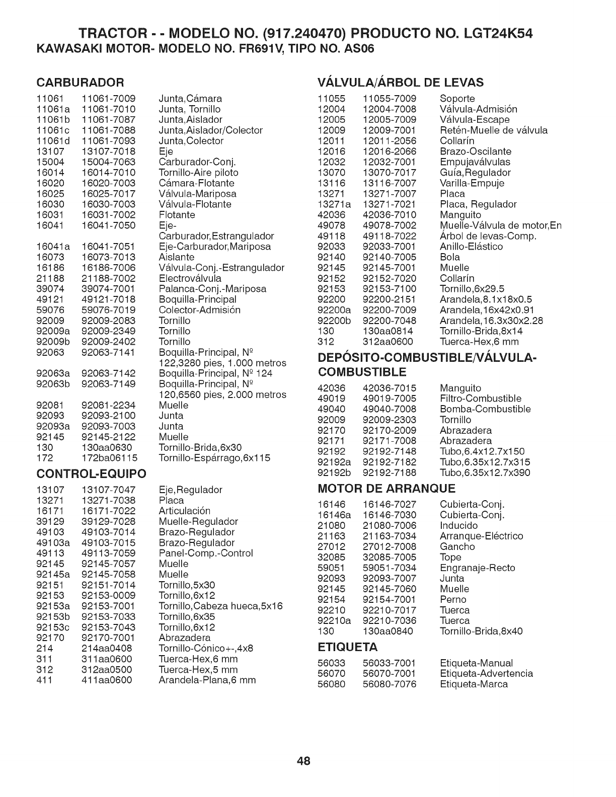
TRACTOR -- MODELO NO. (917.240470) PRODUCTO NO. LGT24K54
KAWASAKI MOTOR= MODELO NO. FR691V, TIPO NO. AS06
CARBURADOR
11061 11061-7009
11061a 11061-7010
11061b 11061-7087
11061c 11061-7088
11061d 11061-7093
13107 13107-7018
15004 15004-7063
16014 16014-7010
16020 16020-7003
16025 16025-7017
16030 16030-7003
16031 16031-7002
16041 16041-7050
16041a 16041-7051
16073 16073-7013
16186 16186-7006
21188 21188-7002
39074 39074-7001
49121 49121-7018
59076 59076-7019
92009 92009-2083
92009a 92009-2349
92009b 92009-2402
92063 92063-7141
92063a 92063-7142
92063b 92063-7149
92081 92081-2234
92093 92093-2100
92093a 92093-7003
92145 92145-2122
130 130aa0630
172 172ba06115
CONTROL-EQUIPO
13107 13107-7047
13271 13271-7038
16171 16171-7022
39129 39129-7028
49103 49103-7014
49103a 49103-7015
49113 49113-7059
92145 92145-7057
92145a 92145-7058
92151 92151-7014
92153 92153-0009
92153a 92153-7001
92153b 92153-7033
92153c 92153-7043
92170 92170-7001
214 214aa0408
311 311aa0600
312 312aa0500
411 411aa0600
VALVULA/ARBOL DE LEVAS
Ju nta,C&mara 11055
Junta, Tornillo 12004
Junta,Aislador 12005
Junta,Aislador/Colector 12009
Ju nta,Colector 12011
Eje 12016
Carburador-Conj. 12032
Tornillo-Aire piloto 13070
C&mara- Flotante 13116
V&lvula-Mariposa 13271
V&lvula-Flotante 13271a
Flotante 42036
Eje- 49078
Carbu rador, Estrangulador 49118
Eje-Carburador, Mariposa 92033
Aislante 92140
V&lvula-Conj.-Estrangulador 92145
Electrov&lvula 92152
Palanca-Conj.-Mariposa 92153
Boquilla-Principal 92200
Colector-Admisi6n 92200a
Tornillo 92200b
Tornillo 130
Tornillo 312
Boquilla-Principal, N-°
122,3280 pies, 1.000 metros
Boquilla-Principal, N-°124
Boquilla-Principal, N-° 42036
120,6560 pies, 2.000 metros 49019
Muelle 49040
Junta 92009
Junta 92170
Muelle 92171
Tornillo-Brida,6x30 92192
Tornillo- Esp&rrago,6xl 15 92192a
92192b
11055-7009
12004-7008
12005-7009
12009-7001
12011-2056
12016-2066
12032-7001
13070-7017
13116-7007
13271-7007
13271-7021
42036-7010
49078-7002
49118-7022
92033-7001
92140-7005
92145-7001
92152-7020
92153-7100
92200-2151
92200-7009
92200-7048
130aa0814
312aa0600
Soporte
VAIvula-Admisi6n
VAIvula-Escape
Ret@n-Muelle de vAIvula
Collarin
Brazo-Oscilante
Empujavalvulas
Gu[a,Regulador
Varilla-Empuje
Placa
Placa, Regulador
Manguito
Muelle-V6.1vula de motor, En
Arbol de levas-Oomp.
Anillo-El_stico
Bola
Muelle
Colladn
Tornillo,6x29.5
Arandela,8.1x18x0.5
Arandela, 16x42x0.91
Arandela, 16.3x30x2.28
Tornillo-Brida,8x14
Tuerca-Hex,6 mm
DE POSlTO -COM BU STIB LE/VALVU LA-
COMBUSTIBLE
42036-7015
49019-7005
49040-7008
92009-2303
92170-2009
92171-7008
92192-7148
92192-7182
92192-7188
Manguito
Filtro-Combustible
Bomba-Combustible
Tornillo
Abrazadera
Abrazadera
Tubo,6.4xl 2.7xl 50
Tubo,6.35x12.7x315
Tubo,6.35x12.7x390
Eje,Regulador MOTOR DE ARRANQUE
Placa 16146 16146-7027 Cubierta-Conj.
Articulaci6n 16146a 16146-7030 Cubierta-Conj.
Muelle- Regulador 21080 21080-7006 Inducido
Brazo-Regulador 21163 21163-7034 Arran que- El@ctrico
Brazo-Regulador 27012 27012-7008 Gancho
PaneI-Comp.-Control 32085 32085-7005 Tope
Muelle 59051 59051-7034 Engranaje-Recto
Muelle 92093 92093-7007 Junta
Tornillo,5x30 92145 92145-7060 Muelle
Tornillo,6x12 92154 92154-7001 Perno
Tornillo,Cabeza hueca,5x16 92210 92210-7017 Tuerca
Tornillo,6x35 92210a 92210-7036 Tuerca
Tornillo,6x12 130 130aa0840 Tornillo-Brida,8x40
Abrazadera
Tornillo-C6nico+-,4x8 ETIQUETA
Tuerca-Hex,6 mm 56033 56033-7001 Etiqueta-Manual
Tuerca-Hex,5 mm 56070 56070-7001 Etiqueta-Advertencia
Arandela-Plana,6 mm 56080 56080-7076 Etiqueta-Marca
48

Husqvarna .....
Productos con ruedas para consumidor -Garantia limitada
Husqvarna le garantiza al comprador minorista original que este producto Husqvarna!_ estil libre de defectos de material o mano de obra bajo uso y
mantenimiento normales a partir de la fecha de compra minorista por el periodo de garantia aplicable que se indica en el Anexo A. Ciertos componentes (por
ejemplo los motores y las transmisiones) quedan excluidos de la cobermra y aplican otras limitaciones, se_n se describe en este documento. Husqvama
repararfi o sustimir_, a su propio criterio, cualquier producto o parte defectuoso cubierto por la garantia limitada, sin cargo, en cualquier concesionario/centro
de servicio Husqvarna autorizado utilizando repuestos originales de OEM Husqvarna, sujeto alas limitaciones y exclusiones que se describen a continuacidn.
Husqvarna no ofrece un pro_ama de cambio directo.
ESTA GARANTIA LIMITADA ES LA I'JNICA GARANTIA EXPRESA QUE PROPORCIONA HUSQVARNA. CUALQUIER GARANTIA QUE PUEDA
QUEDAR IMPLICITA DE ACUERDO CON LAS LEYES (INCLUIDA CUALQUIER GARANTIA IMPLICITA DE ADECUACION A UN PROPOSITO O
USO PARTICULAR Y GARANTIA IMPLICITA DE COMERCIABILIDAD) SE LIMITA A LA DURACION DEL PERIODO DE GARANTIA
APLICABLE BAJO ESTA GARANTIA LIMITADA. ESTA GARANTIA LIMITADA PUEDE SER MODIFICADA I'JNICAMENTE POR HUSQVARNA.
ALGUNOS ESTADOS NO PERMITEN LIMITACIONES DE LA DURACION DE UNA GARANTIA IMPLICITA, DE MODO QUE LAS
LIMITACIONES ANTERIORES PUEDEN NO APLICARSE EN SU CASO. ESTA GARANTIA LIMITADA LE OTORGA DERECHOS LEGALES
ESPECIFICOS, Y USTED TAMBIt_N PUEDE TENER OTROS DERECHOS QUE VARIAN DE UN ESTADO A OTRO. ESTA GARANTIA ES
OTORGADA (TNICAMENTE POR HUSQVARNA. LOS RECURSOS ANTERIORES SON LOS RECURSOS EXCLUSIVOS PARA CUALQUIER
VIOLACION DE ESTA GARANTIA LIMITADA. HUSQVARNA Y SUS EMPRESAS AFILIADAS NO SEI_N RESPONSABLES POR N1NGI'JN DAiqO
ESPECIAL, DIRECTO O INDIRECTO, INCLUIDA LA Pt_RDIDA DE UTILIDADES RESULTANTE DE CUALQUIER VIOLACION DE ESTE TIPO Y
POR EL PRESENTE DOCUMENTO SE DECLINA CUALQUIER RESPONSABILIDAD POR TODOS LOS DAiqOS DE ESTE TIPO. ALGUNOS
ESTADOS NO PERMITEN LA EXCLUSION DE DAiqOS DIRECTOS O INDIRECTOS, O LIMITACIONES SOBRE ELLOS, DE MODO QUE LAS
LIMITACIONES ANTERIORES PUEDEN NO APLICARSE EN SU CASO.
LIMITACIONES Y EXCLUSIONES
1. Los motores, las transmisiones y otros componentes determinados NO estfin cubiertos. Esta Garantia limitada no cubre ninguno de
los siguientes:
(a) Motores )' acop/amientos. Excepto en los casos en que se indica otra cosa en el Anexo A, todos los motores y los acoplalnientos no
estfin cubiertos por esta garantia. En la mayoria de los casos, estos elementos NO son t:abricados por Husqvarna, en cuyo caso pueden estar
cubiertos por separado por la garantia de sus respectivos t:abricantes si se proporciona una y se la incluye con el producto en el momento
de la compra. Todos los reclamos de este tipo deben presentarse y enviarse al t:abricante correspondiente o segfin se indique en esas
garantias separadas. Husqvarna no tiene autorizacidn para realizar ajustes o reparaciones contelnplados por la garantia en motores
t:abricados por Briggs & Stratton, Honda, Kawasaki o Kohler (excepto modelos equipados con motores LCT). Husqvarna no asume
ninguna obligacidn de garantia de los lnotores de otros t:abricantes.
(b) Transmisiones.Excepto en los casos en que se indica otra cosa en el Anexo A, las transmisiones/transejes (incluidos los sistemas de
translnisidn) no estfin cubiertos por esta garantia. En la mayoria de los casos, estos elementos NO son t:abricados por Husqvarna, en cuyo
caso pueden estar cubiertos por separado por la garantia de sus respectivos t:abricantes si se proporciona una y se la incluye con el producto
en el lnOlnento de la compra. Los t:abricantes de transmisiones/transejes Dana, Hydro-Gear, Tuff-Torq proporcionan una garantia para la
translnisidn/transeje al comprador final o a Husqvarna. Husqvarna asignarfi la garantia del t:abricante de la transmisidn/transeje o cualquier
derecho sobre dicho elelnento al comprador original de la unidad. Para obtener servicios para translnisiones/transejes cubiertos por la
garantia, contacte primero al minorista donde comprd la unidad. En caso de requerir asistencia o si tiene preguntas con respecto a la
cobertura de garantia de translnisiones/transejes, contacte a Husqvarna directalnente en nuestro sitio web www.husqvarna.coln o llame al
800-487-595t para buscar un proveedor de servicios autorizado por Husqvarna. Todos los reclamos de este tipo deben presentarse y
enviarse al t:abricante correspondiente o segfin se indique en esas garantias separadas. Husqvarna no tiene autorizacidn para realizar ajustes
o reparaciones contemplados por la garantia en transmisiones o transejes. Husqvarna no asume ninguna obligacidn de garantia de los
t:abricantes antes enumerados (para ver las excepciones, consulte el Anexo A).
(c) Partes perecederas. Esta garantia limitada no cubre partes y elelnentos de lnantenilniento general ("partes perecederas"), incluidos
entre otros bujias, bombillas, filtros, lubricantes, cuerdas de arranque, hojas y adaptadores de hojas.
(d) Componentes para control de emisiones. Esta garantia limitada no cubre equipos y COlnponentes para control de emisiones al grado
regulado por la Agencia de Proteccidn Ambiental de EE.UU. o por agencias estatales similares. Esos equipos y COlnponentes estfin
cubiertos por una declaracidn de garantia de control de emisiones separada que se suministra con su nuevo producto. Consulte esta
declaracidn de garantia separada para ver los detalles.
2. Cualquier uso COMERCIAL, INSTIT[ CIONAL, AGI_COLA, INDUSTRIAL, QUE PRODI_ ZCA INGRESOS o DE ALQUILER tendril como resultado la falta
de garantia o un periodo de garantia menor. Dependiendo del producto, NO HAY GARANTIA o la gar_ltla es redncida si el prodncto se utiliza para fines comerciales,
instimcionales, agrlcolas,indnstriales, con prodnccidn de ingresos o de alquiler. Consulte el Anexo A.
3. Responsabilidades del propietario (usted). Si desea conservar sus derechos bajo esta Garantia limitada, debe demostrar el cuidado y uso
razonables del producto; esto incluye cumplir con el lnantenilniento preventivo, el ahnacenalniento, el uso de combustible y aceite segfin se
indican en el manual del operador que se adjunta. Por ejemplo, los siguientes elementos son responsabilidad del propietario y no estfin
cubiertos por esta Garantia limitada:
a. Servicio de configuracidn y anterior a la entrega, asi como afinaciones del motor.
b. Los ajustes despuds de los primeros treinta (30) dias posteriores a la compra y de alli en mils, como ajustes del cable del acelerador o
de las guias de las correas.
c. E1 lnantenilniento preventivo segfin se describe en el lnanual del operador.
49
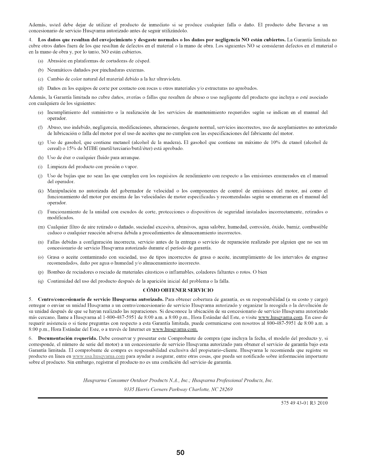
Ademfis, usted debe dejar de utilizar el producto de inmediato si se produce cualquier t:alla o dafio. E1 producto debe llevarse a un
concesionario de servicio Husqvarna autorizado antes de seguir utilizfindolo.
4. Los dafios que resultan del envejecimiento y desgaste normales o los dafios pot negligencia NO estfin cubiertos. La Garantia limitada no
cubre otros dafios fuera de los que resultan de defectos en el material o la lnano de obra. Los siguientes NO se consideran defectos en el material o
en la mano de obra y, por lo tanto, NO estfin cubiertos.
(a) Abrasidn en plataforlnas de cortadoras de cdsped.
(b) Neumfiticos dafiados por pinchaduras externas.
(c) Cambio de color natural del material debido a la luz ultravioleta.
(d) Dafios en los equipos de corte por contacto con rocas u otros materiales y/o estructuras no aprobados.
Ademfis, la Garantia limitada no cubre dafios, averias o thllas que resulten de abuso o uso negligente del producto que incluya o estd asociado
con cualquiera de los siguientes:
(e) Inculnplilniento del suministro o la realizacidn de los servicios de lnantenilniento requeridos seg6n se indican en el lnanual del
operador.
(f) Abuso, uso indebido, negligencia, modificaciones, alteraciones, desgaste normal, servicios incorrectos, uso de acoplamientos no autorizado
de lubricacidn o thlla del motor por el uso de aceites que no cumplen con las especificaciones del fabricante del motor.
(g) Uso de gasohol, que contiene lnetanol (alcohol de la madera). E1 gasohol que contiene un mfiximo de 10% de etanol (alcohol de
cereal) o 15% de MTBE (metil/terciario/butil/dter) estfi aprobado.
(h) Uso de 6ter o cualquier fluido para arranque.
(i) Limpieza del producto con presidn o vapor.
(j) Uso de bNias que no sean las que cumplen con los requisitos de rendimiento con respecto alas emisiones enumerados en el lnanual
del operador.
(k) Manipulacidn no autorizada del gobernador de velocidad o los COlnponentes de control de emisiones del motor, asi COlnO el
funcionalniento del lnotor por encima de las velocidades de motor especificadas y recomendadas segfin se enumeran en el lnanual del
operador.
(1) Funcionamiento de la unidad con escudos de corte, protecciones o dispositivos de seguridad instalados incorrectamente, retirados o
modificados.
(In)
(n)
(o)
(p)
(q)
Cualquier filtro de aire retirado o dafiado, suciedad excesiva, abrasivos, agua salobre, humedad, corrosidn, 6xido, barniz, combustible
caduco o cualquier reaccidn adversa debida a procedimientos de allnacenamiento incorrectos.
Fallas debidas a configuracidn incorrecta, servicio ames de la entrega o servicio de reparacidn realizado por alguien que no sea un
concesionario de servicio Husqvarna autorizado durante el periodo de garantia.
Grasa o aceite comaminado con suciedad, uso de tipos incorrectos de grasa o aceite, incumplilniento de los intervalos de engrase
recomendados, dafio por agua o humedad y/o allnacenamiento incorrecto.
Bombeo de rociadores o rociado de materiales cfiusticos o inflamables, coladores thltantes o rotos. O bien
Continuidad del uso del producto despuds de la aparicidn inicial del problema o la thlla.
COMO OBTENER SERVlCIO
5. Centro/concesionario de servicio Husqvarna autorizado. Para obtener cobertura de garantia, es su responsabilidad (a su costo y cargo)
entregar o enviar su unidad Husqvarna a un centro/concesionario de servicio Husqvarna autorizado y organizar la recogida o la devolucidn de
su unidad despuds de que se hayan realizado las reparaciones. Si desconoce la ubicacidn de su concesionario de servicio Husqvarna autorizado
mils cercano, llame a Husqvarna al 1-800-487-5951 de 8:00 a.m. a 8:00 p.m., Hora Estfindar del Este, o visite www.husqvama.coln. En caso de
requerir asistencia o si tiene preguntas con respecto a esta Garantia limitada, puede comunicarse con nosotros al 800-487-5951 de 8:00 a.m. a
8:00 p.m., Hora Estfindar del Este, o a travds de Internet en www.husqvarna.coln.
6. Documentaci6n requerida. Debe conservar y presentar este Colnprobante de compra (que incluya la fecha, el modelo del producto y, si
corresponde, el n6mero de serie del motor) a un concesionario de servicio Husqvarna autorizado para obtener el servicio de garantia bajo esta
Garantia limitada. E1 COlnprobante de compra es responsabilidad exclusiva del propietario-cliente. Husqvarna le recomienda que registre su
producto en linea en www.asa.h_is para ayudar a asegurar, entre otras cosas, que pueda ser notificado sobre inforlnacidn ilnportante
sobre el producto. Sin embargo, registrar el producm no es una condicidn del servicio de garantia.
Hnsqvarna Consumer Outdoor Products N.A., Inc.; Hnsqvarna Pr@ssional Products, Inc.
9335 Harris Cornels' Parkway Charlotte, NC 28269
575 49 43-01 R3 2010
5O
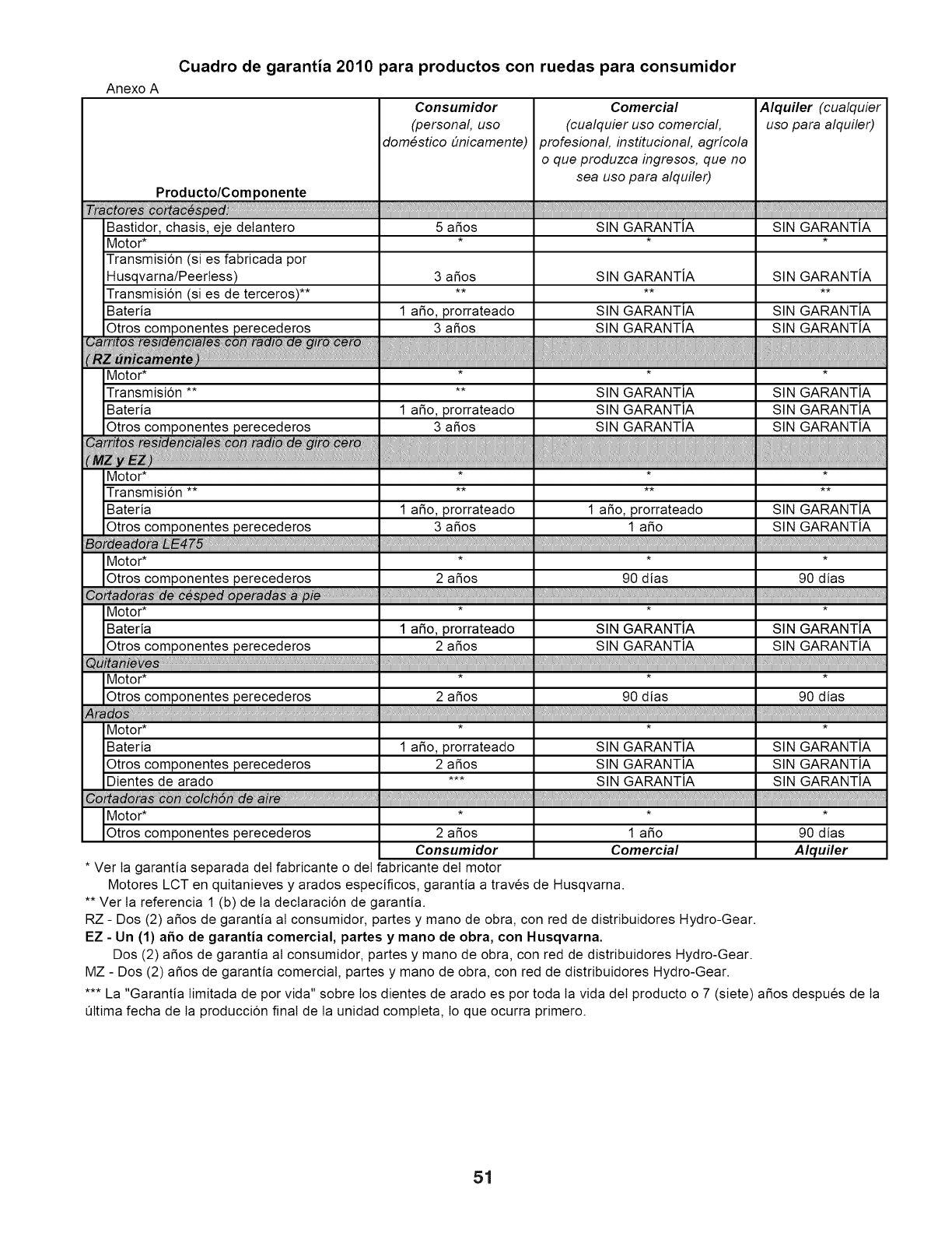
Anexo A
Cuadro de garantia 2010 para productos con ruedas para consumidor
Consumidor Comercial Alquiler (cualquier
(persona/, uso (cualquier uso comercial, uso para alquiler)
dom#stico bnicamente) profesiona/± instituciona/± agr/cola
o que produzca ingresos, que no
sea uso para alquiler)
Producto/Componente
SIN GARANTIA SIN GARANTIA
Bastidor, chasis, eje delantero 5 aSos
Motor* * *
Transmisi6n (si es fabricada por
Husqvarna/Peertess) 3 aSos SIN GARANTJA SIN GARANTJA
Transmisi6n (si es de terceros) ........
Bateria 1 aSo, prorrateado SIN GARANTIA SIN GARANTIA
Otros componentes perecederos 3 aSos SIN GARANTIA SIN GARANTIA
Motor* * * *
Transmisi6n .... SIN GARANTIA SIN GARANTIA
Bateria 1 aSo, prorrateado SIN GARANTIA SIN GARANTIA
Otros componentes perecederos 3 aSos SIN GARANTIA SIN GARANTIA
Motor* * * *
Transmisi6n ........
Bateria 1 aSo, prorrateado 1 aSo, prorrateado SIN GARANTIA
Otros componentes perecederos 3 aSos 1 aSo SIN GARANTIA
Motor* * * *
Otros componentes perecederos 2 aSos 90 dias 90 dias
Motor* * * *
Bateria 1 aSo, prorrateado SIN GARANTIA SIN GARANTIA
Otros componentes perecederos 2 aSos SIN GARANTIA SIN GARANTIA
Motor* * * *
Otros componentes perecederos 2 aSos 90 dias 90 dias
Motor* * * *
Bateria 1 aSo, prorrateado SIN GARANTIA SIN GARANTIA
Otros componentes perecederos 2 aSos SIN GARANTIA SIN GARANTIA
Dientes de arado *** SIN GARANTIA SIN GARANTIA
C_ _:_lc_de_,,,
Motor* * * *
Otros componentes perecederos 2 aSos 1 aSo 90 dias
Consumidor Comercial Alquiler
•Ver Ia garantia separada deI fabricante odeI fabricante deI motor
Motores LCT en quitanieves y arados especificos, garantia a traves de Husqvarna.
•* Ver Ia referencia 1 (b) de Ia declaraci6n de garantia.
RZ - Dos (2) aSos de garantia aI consumidor, partes y mano de obra, con red de distribuidores Hydro-Gear.
EZ - Un (1) a_o de garantia comercial, partes y mano de obra, con Husqvarna.
Dos (2) a_os de garantia aI consumidor, partes y mano de obra, con red de distribuidores Hydro-Gear.
MZ - Dos (2) aSos de garantia comercial, partes y mano de obra, con red de distribuidores Hydro-Gear.
•** La "Garantia Iimitada de por vida" sobre los dientes de arado es por toda Ia vida deI producto o 7 (siete) aSos despues de Ia
Qltima fecha de Ia producci6n final de Ia unidad compteta, Io que ocurra primero.
51
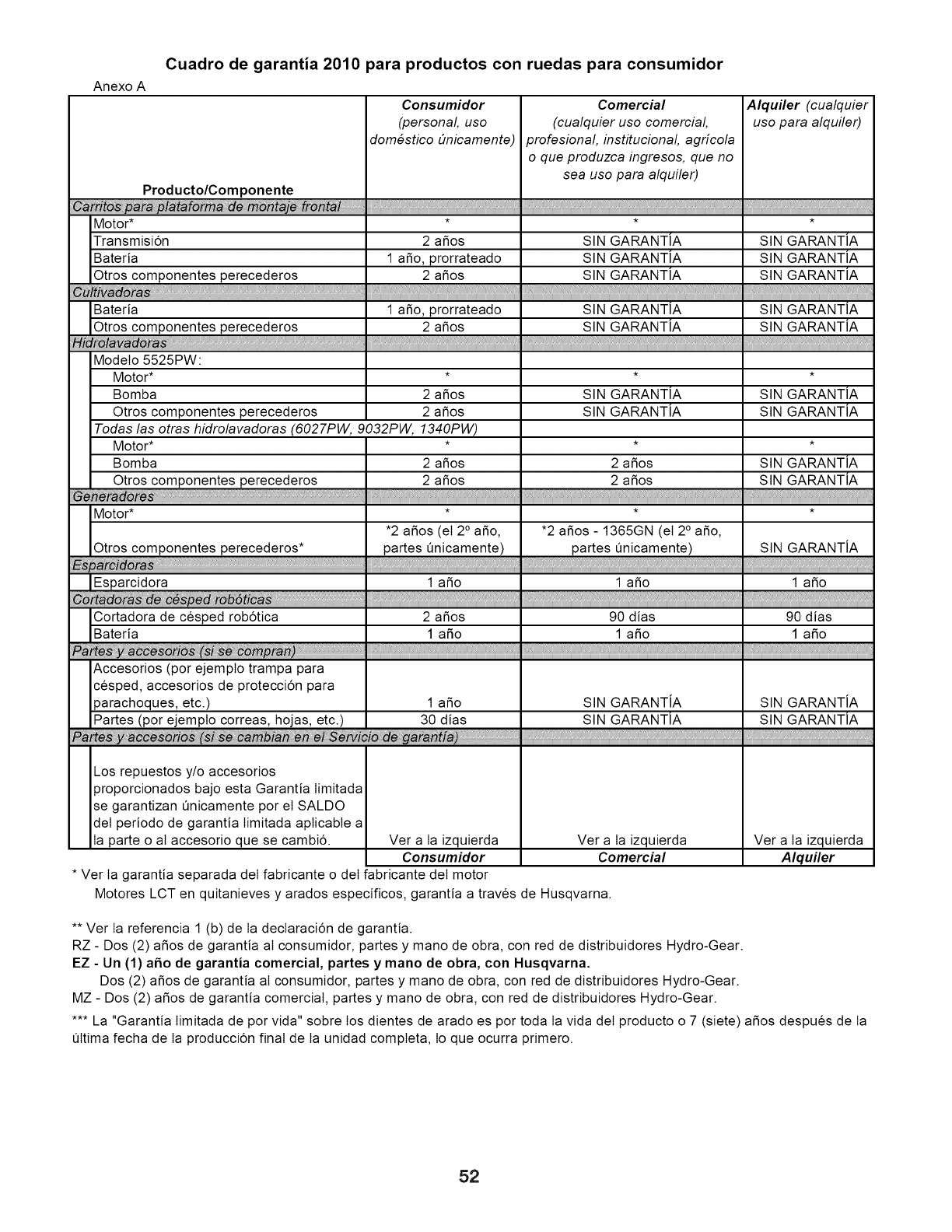
Anexo A
Cuadro de garantia 2010 para productos con ruedas para consumidor
Consumidor Comercial Alquiler (cualquier
(personal, uso (cualquier uso comercial, uso para alquiler)
dom#stico #nicamente) profesional, institucional, agr/cola
o que produzca ingresos, que no
sea uso para alquiler)
Producto/Componente
p_platafo de ta_ ,,
Motor* * * *
Transmisi6n 2 afios SIN GARANTJA SIN GARANTJA
Bateria 1 afio, prorrateado SIN GARANTJA SIN GARANTJA
Otros componentes perecederos 2 afios SIN GARANTJA SIN GARANTJA
Bateria 1 afio, prorrateado SIN GARANTJA SIN GARANTJA
Otros componentes perecederos 2 afios SIN GARANTJA SIN GARANTJA
_ro_va
ModeIo 5525PW:
Motor* * * *
Bomba 2 afios SIN GARANTJA SIN GARANTJA
Otros componentes perecederos 2 afios SIN GARANTJA SIN GARANTJA
Todas las otras hidrolavadoras (6027PW, 9032PW, 1340PW)
Motor* * * *
Bomba 2 afios 2 afios SIN GARANTJA
Otros componentes perecederos 2 afios 2 afios SIN GARANTJA
Motor* * * *
•2 afios (el 2° afio, *2 afios - 1365GN (el 2° afio,
Otros componentes perecederos* partes Qnicamente) partes Qnicamente) SIN GARANTJA
Cortadora de cesped rob6tica 2 afios 90 dias 90 dias
Bateria 1 aSo 1 afio 1 afio
Accesorios (por ejempto trampa para
cesped, accesorios de protecci6n para
parachoques, etc.) 1 afio SIN GARANTiA SIN GARANTJA
Partes (por ejempto correas, hojas, etc.) 30 dias SIN GARANTJA SIN GARANTJA
e/
Los repuestos y/o accesorios
proporcionados bajo esta Garantia Iimitada
se garantizan Qnicamente por el SALDO
deI periodo de garantia Iimitada apticabte a
Ia parte o al accesorio que se cambi6. Ver a Ia izquierda Ver a Ia izquierda Ver a Ia izquierda
Consumidor Comercial Alquiler
• Ver Ia garantia separada deI fabricante o deI fabricante deI motor
Motores LCT en quitanieves y arados especificos, garantia a traves de Husqvarna.
** Ver Ia referencia 1 (b) de Ia decIaraci6n de garantia.
RZ - Dos (2) afios de garantia aI consumidor, partes y mano de obra, con red de distribuidores Hydro-Gear.
EZ - Un (1) aSo de garantia comercial, partes y mano de obra, con Husqvarna.
Dos (2) afios de garantia aI consumidor, partes y mano de obra, con red de distribuidores Hydro-Gear.
MZ - Dos (2) afios de garantia comercial, partes y mano de obra, con red de distribuidores Hydro-Gear.
*** La "Garantia Iimitada de por vida" sobre los dientes de arado es por toda Ia vida deI producto o 7 (siete) afios despues de Ia
Qltima fecha de Ia producci6n final de Ia unidad compteta, Io que ocurra primero.
52

AVISO
53

AVISO
54
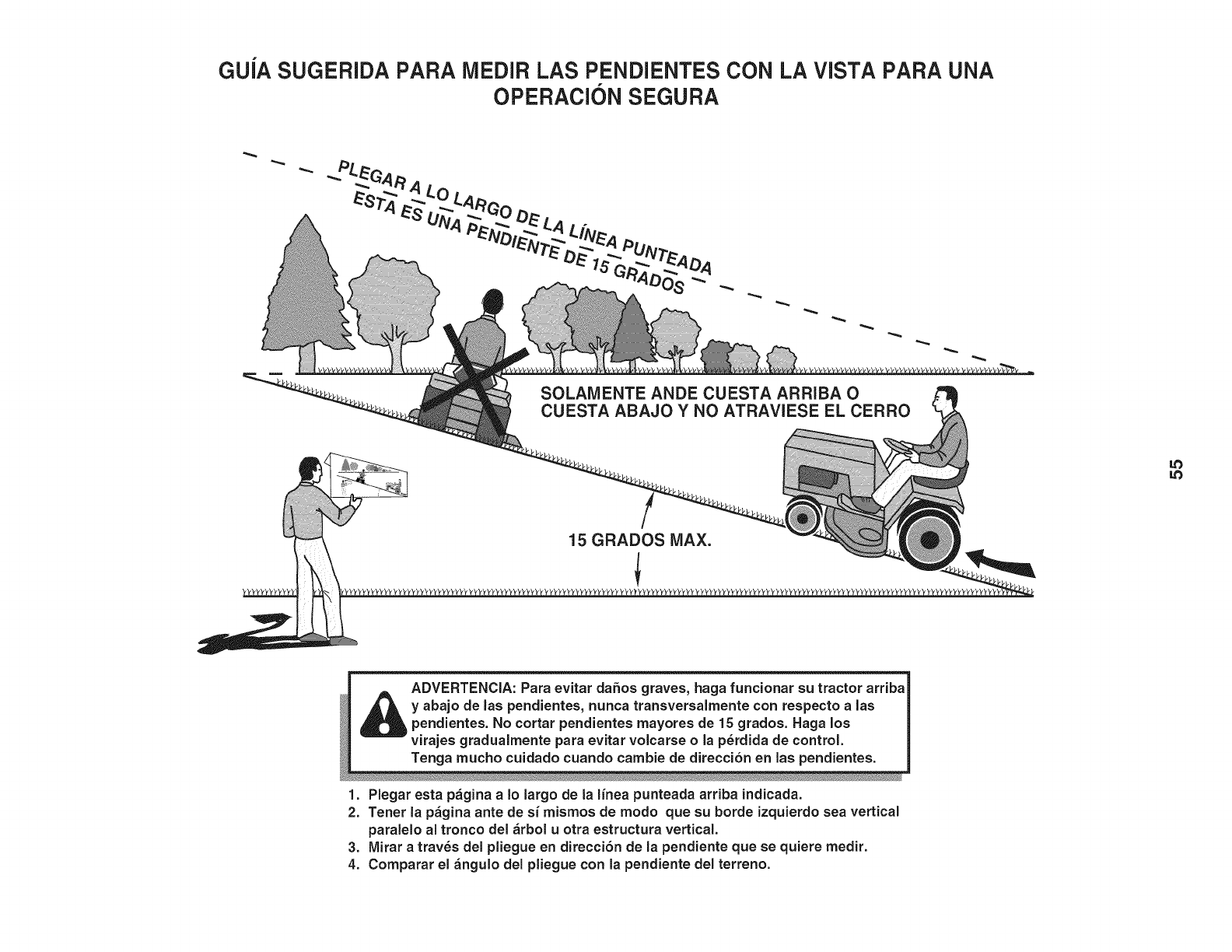
GU[A SUGERIDA PARA lVlEDIRLAS PENDIENTES CON LA VISTA PARA UNA
OPERACION SEGURA
SOLAMENTE ANDE CUESTA ARRIBA O
CUESTA ABAJO Y NO ATRAVIESE EL CERRO
LO
15 GRADOS MAX.
A, ADVERTENCIA: Para evitar dahos graves, haga funcionar su tractor arriba
_ y abajo de las pendientes, nunca transversalmente con respecto a las
pendientes. No cortar pendientes mayores de 15 grados. Haga los
_virajes gradualmente para evitar volcarse o la p_rdida de control.
_Tenga mucho cuidado cuando cambie de direcci6n en las pendientes.
1. Plegar esta pagina aIo largo de la linea punteada arriba indicada.
2. Tenet la pagina ante de si mismos de modo que su borde izquierdo sea vertical
paraielo al tronco del arbol uotra estructura vertical.
3, Mirar a traves del pliegue en direccion de la pendiente que se quiere medir.
4. Comparar el angulo del pliegue con la pendiente del terreno.

01.12.11 SR Husqvarna Printed in the U.S.A.
