Hussman Dccg Users Manual
HUSSMANN Dipping and Display Case to the manual 5596a52b-c7de-4bec-b3af-b02f7cd7ecde
2015-02-05
: Hussman Hussman-Dccg-Users-Manual-403441 hussman-dccg-users-manual-403441 hussman pdf
Open the PDF directly: View PDF ![]() .
.
Page Count: 18
January 2006
HUSSMANN - GLOVERSVILLE
INSTALLATION & SERVICE
INSTRUCTIONS
FOR
DCCG and DCSG (-D) MODELS
Dipping and Display Case
P/N OII – DCCG - DCSG
January 2006
First Call for help (US and Canada):
1-800-922-1919
Soporte Tècnico y Asistencia (Mèxico):
01-800-522-1900
For a Service Network Locator and other
Information visit us at
www.hussmann.com
select Worldwide Locations
TABLE OF CONTENTS
Introduction
3
Inspection 3
Specifications
Construction
3
Cabinet Dimensions 4
Cabinet Capacities 4
Electrical Data
4
Installation and Start Up
5
Location
5
Power Requirements 5
Start
Up
Procedures
5
Operation
and
Maintenance
Temperature
Control
6
Display Lighting 6
Anti-sweat Heaters 6
Defrosting 6
Condensing Unit 7
Cleaning the Condenser 7
Cleaning Exterior 7
Cleaning Interior 7
Serial Plate Location and Refrigerant Charges 7
Temperature Control Replacement 7
Operational
Data
8
Trouble
Shooting
Chart
8
-
9
1
TABLE OF CONTENTS CON’T
Dipping
Using
Guide
Loading
10
Storage 10
Lids 10
Temperature Control 10 -11
Load Limits 11
Dipping
11
Maintenance
11
Warranty
and
Parts
Information
12
-
13
2

INTRODUCTION, INSPECTION, SPECIFICATIONS
INSTALLATION and START UP
INTRODUCTION
–
The DCSG/DCCG-4 8, 12, and 16
are
specifically designed for
dipping/display
of bulk ice cream, sherbet, or froz
en
yogurt. Wide glass front and one-
piece
molded lids provide an unobstructed
view
of the product for impulse merchandising.
Optional items include easy to use
can
holder trays and dipper wells. The –
D
models on -8, -12 and -16 include
the
labor saving storage doors feature.
INSPECTION –
Upon receipt of the cabinet, ca
refully
examine the crating for damage.
If
damage is found, make anote on
the
delivery ticket before signing.
Carefully
remove shipping crate and examine
the
cabinet for “concealed” damage.
If
damage is found contact the
delivering
carrier immediately and have his
agent
prepare an inspection report for
the
purpose of filing aclaim.
This is your
responsibility.
durability. The entire assembly is
then
chemically treated and finished w
ith
baked-on powder paint.
The liner is an all welded assembly
of
electro zinc steel. Copper
evaporator
tubing is fastened to the liner
and
applying aconductive material on
both
top and bottom of the tubing
further
enhances maximum heat transfer.
The
liner is also chemically treated
and
painted with baked-on powder paint.
All models incorporate aslide-ou
t
condensing unit for easy access to a
ll
components.
SPECIFICATIONS
CONSTRUCTION
–
The base is an all welded assembly o
f
heavy dusty steel to provide a
strong
frame on which the rest of the cabinet
is
built.
The shell is formed from heavy
gauge
steel, welded together as an assembly,
and
then welded to the base for strength and
3

CABINET DIMENSIONS
–
Cabinet
Dimensions (inches)
Model Length Width Height Ship
DCSG/DCCG Outside Inside Outside * Inside Outside Wt.
-4 25 3/8 21 25 13/16 21 ½ 51 ¼
260
-8 47 7/16 43 1/8 25 13/16 21 1/2 51 1/4 405
-12 67 5/16 63 25 13/16 21 1/2 51 1/4 515
-16 87 7/16 83 1/8 25 13/16 21 1/2 51 1/4 625
* -D models (with doors) outside width = 27 9/16
CABINET CAPACITIES
–
Cabinet
Model Cu. Capacity (9 1/2 dia. 3 gal cans) # of lids
DCSG/DCCG Ft. Upper Display Lower Display
-4 3.3 4 - 1
-8 8.9 8 4 1
-12 14.5 12 8 2
-16 20.2 16 12 2
(Capacities of D models are the same as models without doors)
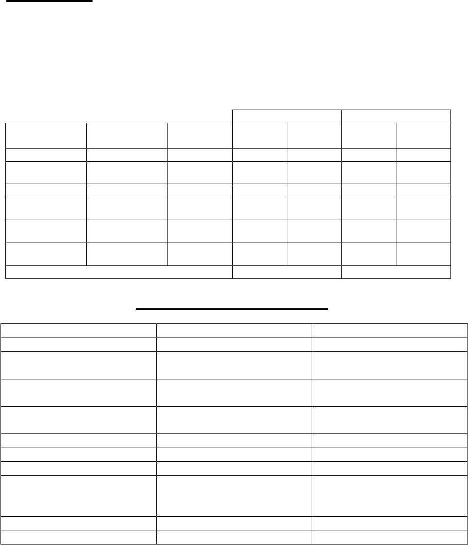
ELECTRICAL DATA
Cabinet Compressor Cabinet *
Model Volts HP L.R. F.L. Nominal Fuse
DCSG/DCCG Amps Amps Run Amps Amps
-4 115 1/3 33.0 6.4 6.9 15
-8 115 1/2 58.0 8.6 9.5 15
-12 115 1/2 45.0 7.8 9.9 15
-16 115 3/4 59.8 10.2 10.5 15
(electrical data of D models are the same as standard models)
* Includes main top heaters and
condenser
fan motors
Due to compressor change from semi-hermetic to hermetic these are the value changes
-8 (*hermetic)
115
½
51.0
.9
8.4
15
-12 (*hermetic) 115 ½ 87.0 7.9 12.0 15
*
effective
Aug.
2002
the
DCCG/DCSG-8
compressor
changed
from
a
semi-hermetic
HA TB-00 5E-IAA to her metic T2155GK .
*
effective
Nov.
2003
the
DCCG/DCSG-12
compressor
changed
from
a
semi-hermetic
KAGB-0050-IAA to hermetic J2212GK Aspera
4

INSTALLATION and
START UP
LOCATION –
The location of your cabinet is
important.
Make sure your selected location is
NOT
in any of the following areas as it cou
ld
seriously affect the operation.
•
Not in direct sunlight.
•
Not in the air path of heat or air
conditioning ducts.
•
Not at an exit or entrance affected by
extreme temperature change.
Allow 2 feet of clearance at the rear of
the
case to allow adequate air
movement
across the condenser for
proper
refrigeration system performance, do
not
obstruct the grille at the rear intake
and
discharge. If desired, the blank off
panel
behind the front (customer side)
louvered
panel –may be removed for rear
air
intake and front air discharge, but
then
insure 2 feet of unobstructed clearance
is
left at the case front.
Level case front to back and end to
end,
shimming where necessary
upon
installation to assure proper op
erating
drains, and refrigeration system.
equipment on the same circuit. Use
a
time delay fuse or circuit breaker.
The
supply circuit must be properly
grounded
and conform to National and
Local
Electrical Codes. Voltage, as measured
at
the compressor terminals
during
operation, must not vary more than
5%
from cabinet serial plate rating. If a
low
voltage condition exists, contact
your
electrician or power company.
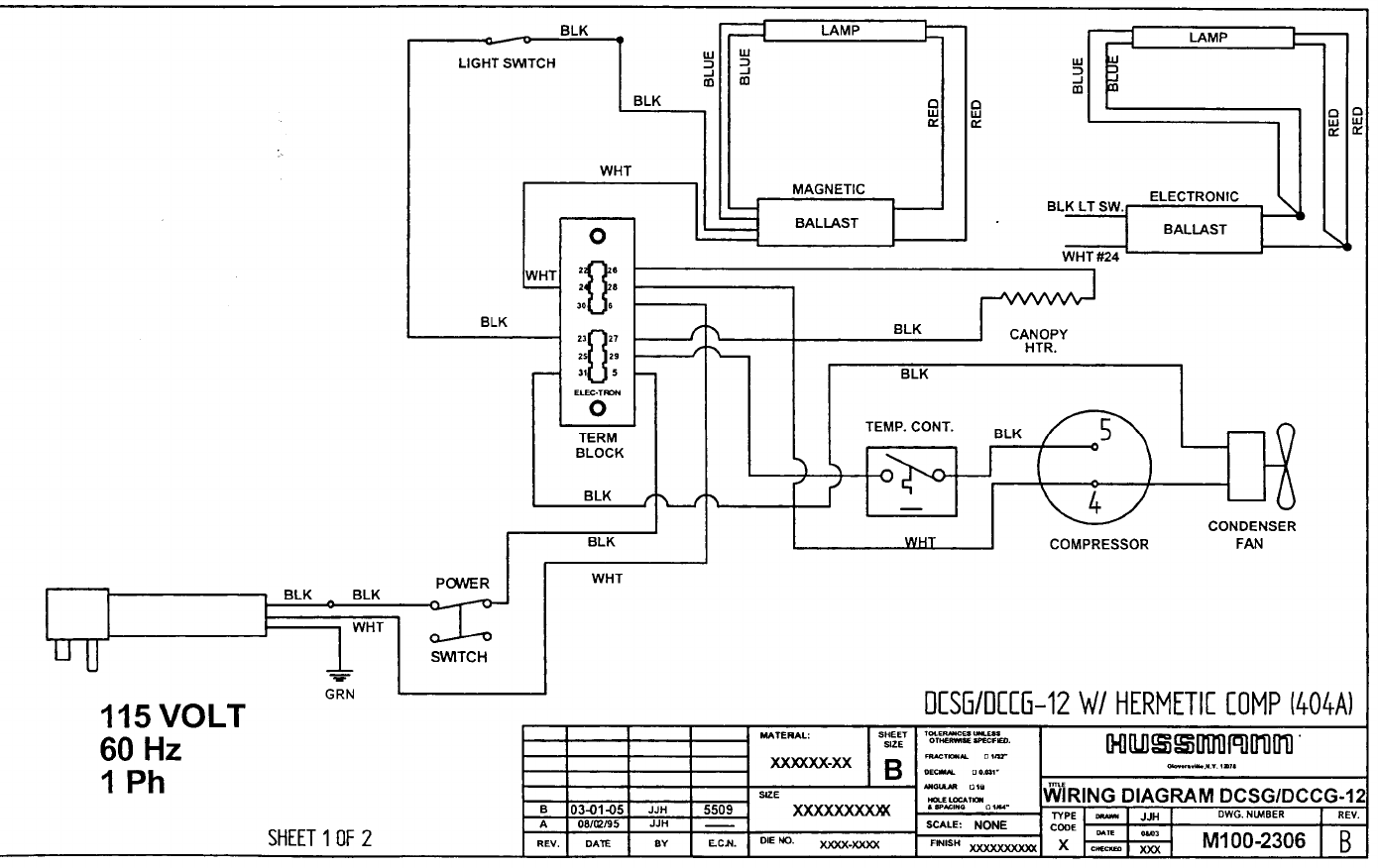
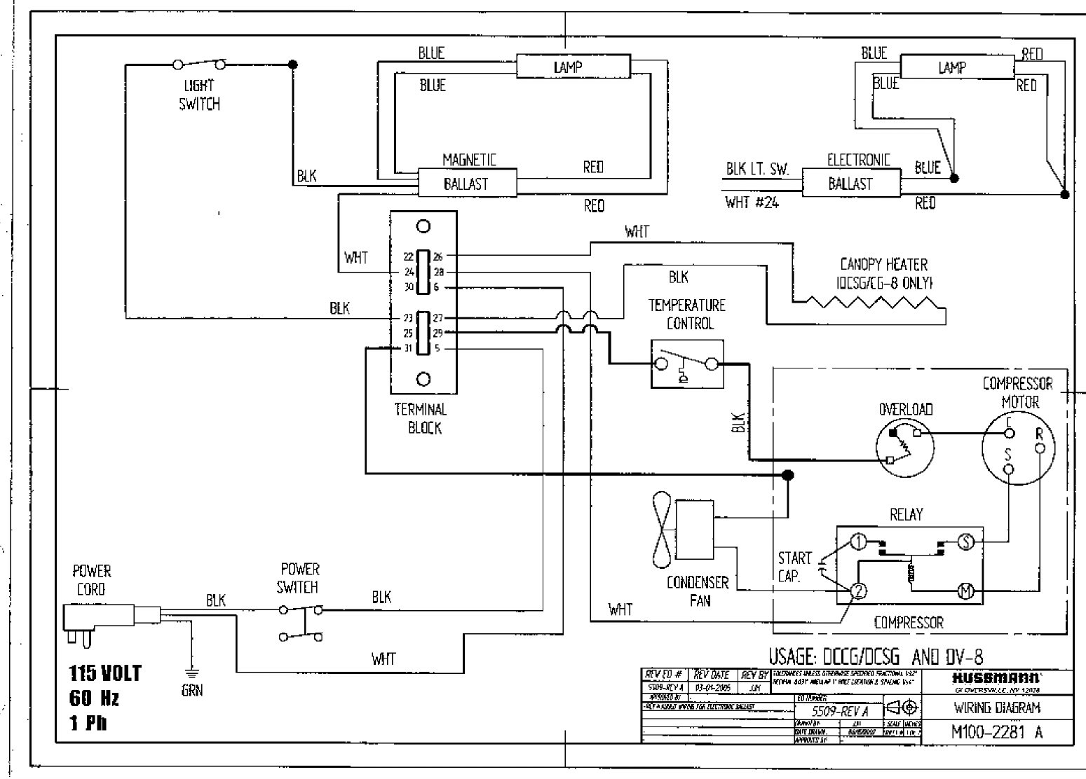
Awiring diagram is provided on the
condenser shroud for each unit.
A power (ON-OFF) switch is provided
on
each model. The switch is accessib
le
through ahole provided in the rear
(operator side) access panel
STAR T UP P ROCE DURE -
•
Cut the band which holds
the
compressor in place during shipment.
•
Make sure fan turns freely. Check
for
any connections or parts that
might
have loosened during shipment.
•
Start cabinet, and allow
temperature
to pull down to normal level
before
loading product.
POWER REQUIREMENTS
–
The DC models are equipped with
a
three-wire grounded service core for
your
protection. The cabinets are designed
to
operate on 115V single-phase
60hz
current. Aseparate circuit
is
recommended to prevent product loss
due
to
overloading
or
malfunction
of
other
5

OPERATION AND MAINTENANCE
SERVICING DATA AND
PROCEDURES
OPERATION and
MAINTENANCE
TEMPERATURE CONTROL –
The thermostat, which senses the
cold
wall temperature, is located at the low
er
rear right corner of the cabinet
through
the access panel. It has been pre-set
at
the factory to maintain
product
temperatures between +10° and +4°.
The
thermostat is adjustable. If other
than
normal temperatures are required,
adjust
the control by turning the knob clockw
ise
for colder and counter-clockwise fo
r
warmer temperatures.
DISPLAY LIGHTING –
All models are equipped with
fluorescent
light fixtures installed in the canopy.
An
ON-OFF switch is located in the
right
service side of the canopy and is
so
labeled.
ANTI-SWEAT HEATERS –
Aresistance heater is installed in
the
perimeter of the base frame of the
canopy
to prevent condensation. Continuity
of
the heater circuit maybe checked at th
e
splice located inside the ballast
enclosure
in the compressor compartment.
Should the heater fail it may be replaced
by:
•
Raise top and canopy as an assembly
and place wood spacers between
top
and cabinet.
•
Remove heater from under base
frame.
•
Disconnect spade terminal splices and
remove.
•
Reassemble reverse order –
resistance
heater wire must be taped back
into
position
DEFROSTING –
It must be recognized that
accumulation
of frost on the cabinet walls does
impair
refrigeration. Daily scraping of
the
interior walls with a plastic scraper w
ill
extend the length of time betw
een
complete defrosting.
Most installations will require a c
omplete
defrosting every seven to ten
days.
Usually the best time to defrost is at
the
close of business so the cabinet will
be
regulated for the start of the nex
t business
day.
The ice cream should be removed
from
the cabinet and placed in awalk-in
or
storage freezer during the
defrosting
operation. Apower switch for
turning
the case off for defrosting is
located
through the access panel.
•
Remove screws holding aluminum top
to cabinet.
Defrosting may be accomplished with
the
aid of a hair dryer, plastic scraper or
by
merely letting the cabinet remain
open
until the walls are cleared. Care should
6

be taken not to puncture the inter
ior
walls or remove paint from the w
alls
during this procedure.
Be sure to disconnect power from
the
cabinet prior to starting
defrost
operation. After the cabinet is co
mpletely
defrosted, wash thoroughly,
remove
defrost water (Hussmann dipping
cases
are provided with an outside
drain
located on the operator’s side of the
case
base to assist you in this operation), w
ipe
the interior dry, and turn the power
back
on.
Be sure to allow the cabinet to cool dow
n
to its operating temperature
before
reloading.
CONDENSING UNIT –
The condensing unit is mounted on
a
slideout base, accessible by removing
the
rear serving side access panel.
The
condenser is of the baretube design.
The
condenser fan motor draws the
air
through the rear access panel, across
the
compressor and discharges back out
the
rear access panel unless the case has
been
Field converted to front air discharge
as
previously discussed in the
Location
section of this manual.
For this reason, if
the case is installed in a counter, provisions
must be made for the release of the
discharge air.
CLEANING THE CONDENSER –
To clean condenser, a soft, nylon
brush
should be used to loosen dirt and
lint.
Then vacuum up the dirt or
blow
condenser out with ahigh-pressure
gas
such as nitrogen. Never use a wire
brush
to clean condenser tubes.
CLEANING EXTERIOR / INTERIOR –
When cleaning the exterior of the
cabinet
use a soft cloth or sponge with water
and
mild detergent. Rinse and wipe dry.
For cleaning the interior of the
product
compartment, abuilt-in drain has
been
provided with astandard hose
fitting
located at the front of the cabinet in
the
base area. Disconnect the
electrical
power and allow cabinet to warm
to
above freezing temperature. Use a
soft
cloth or sponge with a mild detergent
to
wash the interior. Wipe dry
before
restarting the cabinet. Allow the
cabinet
to cool down to proper
temperature
before reloadin g produc t.
SERIAL PLA TE LOC A TION –
One serial plate is located on the interio
r
left wall of the cabinet, and a second
one
in the condensing unit
compartment.
Both contain all pertinent infor
mation
such as model, serial number,
amperage
rating, refrigerant type and charge,
etc.
Specific charges are DCSG/DCCG-4
16
oz.,DCSG/DCCG-8 29 oz., DCSG/DCCG-
12 33 oz., and DCSG/DCCG-16 has
31
oz., all have R-404a. The “D”
models
have the same charge.
TEMPERATURE CONTROL
REPLACEMENT –
The Ranco temperature control is
located
in the compressor compartment.
To
replace, first disconnect power supply
and
remove two screws holding control
dial
plate. Pull capillary tube from
control
well, noting length of tube removed.
Push
new cap tube into well, being careful
not
to kink it, and making certain it
reaches
full depth of well.
7
Replace spade connectors and
reinstall
dial plate and two screws which
hold
control in place.
Operational Data
The following operational data is based on lab tests, and may vary under field
conditions. The conditions shown at the non-recommended high 85°F ambient are shown
for information only and a possible reason for jobsite problems. Note that during August,
2002, the DCC/SG-8 cases changed from semi-hermetic (SH) to hermetic (H) and similarly,
during December, 2003, the DCC/SG-12 cases changed from the semi-hermetic (SH) to
hermetic (H) style compressors which operate under different pressures.
75°F
85°F
Model Compressor
Compressor
Type
Suction
Pressure
Head
Pressure
Suction
Pressure
Head
Pressure
DCC/SG-4
NE2134GK
H
9
230-240
10
260-270
HATB-005E-
DCC/SG-8 &-D
CAA
SH
6
230-240
7
245-255
DCC/SG-8 &-D
T2155GK
H
9
230-240
10
235-245
DCC/SG-12 &-
D
DCC/SG-12 &-
KAGB-005E-
IAA SH 6235-245 7250-260
D
J2212GK
H
10
230-240
11.5
260-270
DCC/SG-16 &-
D
KAAB-007E-
CAA SH 6270-280 7280-290
Load Line Temperature
0 to +10°F
5 to +12°F
TROUBLE SHOOTING CHART
TROUBLE
PROBABLE
CAUSE
SOLUTION
Compressor will not start,
no noise
1. Power disconnected 1. Check service cord for
proper connection
2. Blown fuse or breaker 2. Replace fuse or reset
breaker
3. Defective or broken
wiring
3. Repair or replace
4. Defective overload
4. Replace
5. Defective te mperature 5. Replace control
Compressor will not start
cuts out on overload
1. Low voltage 1. Check voltage at cabinet.
Should be within 5% of
rating
2. Defective compressor 2. Replace
3. Defective relay
3. Replace
8

4. Restriction pinched cap
tube
4. Repair or replace tube
5. Restriction moisture 5. Leak check, replace drier,
evacuate and recharge
6. Inadequate air over
condenser
7. Defective condenser fan
motor
6. Allow at least 24” at front
and back of unit
compartment
7. Replace
TROUBLE
PROBABLE
CAUSE
SOLUTION
High head pressure
1. Cabinet location too warm
1. Relocated cabinet
2. Restricted condenser air
flow
3. Defective condenser fan
motor
4. Air or non-condensable
gases in system
2. Clean condenser or
remove air flow restriction
3. Replace motor
4. Leak check, change drier,
evacuate and recharge
W arm storage temper atures 1. Temperature control not
set properly
1. Reset control
2. Short of refrigerant 2. Leak check, change drier,
evacuate and recharge
3. Cabinet location too warm 3. Relocate cabinet
4. Too much refrigerant 4. Purge system, change
drier, evacuate and recharge
5. Low voltage, compressor
cycling on overload
5. Check voltage at cabinet.
Should be within 5% of
rating
6. Heavy frost on side walls
6. Defrost cabinet
Compressor runs
continu ously, product too
cold
1. Defective control
1. Replace
2. Control s
ensing element
not completely insta
lled in
well
2. Push control sensing
element into well
3. Short on refrigerant 3. Leak check, change drier,
evacuate and recharge
Compressor runs
continu ously, product too
warm
1. Short on refrigerant 1. Leak check, change drier,
evacuate and recharge
2. Inefficient compressor
2. Replace
9

DIPPING USERS GUIDE
The general success of any ice cream dipping department depends to a great ex
tent on the
people within that department. If at all
possible, a single individual should be assigned the
direct responsibility of assuring that proper
operational procedures are being followed.
LOADING
–
Careful thought should be given to the placement of flavors within the cabinet prior to
the opening of the dipping department. Flavors with the highest sugar content (ripple,
maple syrup, and candy) require a lower temperature for dipping than vanilla. Since
temperatures will vary slightly within the cabinet, it is recommended that these flavors
be placed in the corners where maximum cooling effect from two walls can be taken
adv antage of.
STORAGE
–
In order to assure product quality and minimum energy usage, it is important that
proper attention is given to the maintenance of product temperatures prior to placement
in the display freezer. Storage temperatures are generally maintained at –12 degrees F
to –18 degrees F. This allows for long-term storage of ice cream without deterioration.
Dipping te mperatures are generally maintained at +5 degrees F to +9 degrees F, which
allows for rather limited display time before deterioration begins to occur.
Ice cream removed from a delivery truck, walk-in freezer, or storage cabinet should be
placed in the dipping cabinet immediately.
The dipping cabinet is not designed as a hardening cabinet, and will generally only
maintain ice cream at the preset dipping temperature.
If ice cream is allowed to warm up prior
to placement in the dipping cabinet,
crystallization may occur resulting in some loss of product quality.
LIDS
–
To conserve energy and minimize frost accumulation on the cabinet interior walls, the
lids should remain closed until the customer has made his/her choice of flavors, and
should be closed immediately once the customer has been served. Under no
circumstances should the cabinet lids be left open for extended periods of time.
10

TEMPERATURE CONTROL
–
The temperature control is factory set for normal dipping temperatures. If, after a week
or so of operation, it is decided that a higher or lower temperature is required, only a
qualified refrigeration mechanic should adjust the control. Other than the initial
adjustment and possibly a seasonal adjustment, no other setting should be required. If
the cabinet temperature fluctuates to any great extent, a refrigeration mechanic should
be notified. Employees should not be allowed to tamper within the control setting.
LOA D LIMI TS
–
•
A fully loaded cabinet will use less energy and maintain generally more even
temperatures than one that is only partially full. However, care should be taken not to
exceed the load line limits as noted on the interior cabinet walls through the use of wire
racks, stepshelving, or by stacking containers three high.
DIPPING
–
Much of the success of hand dipping and appeal of the stored ice cream to the customer
depends on the training of personnel in proper dipping methods. Periodic scraping of
the container sidewalls and leveling off of the ice cream is essential to avoid discoloration
and drying out of the ice cream. Scraping the container sidewalls and leveling off the ice
cream should be done lightly with the use of a spade. Start with the back of the spade
turned towards the side of the can, working from the top of the can down. Once the
walls are cleared, the top portion of the remaining ice cream should be leveled off, filling
in holes left by previous dipping.
MAINTENANCE
–
•
Proper maintenance of refrigeration equipment can have a dramatic effect on the
equipment’s ability to perform, as well as power consumption and customer reaction to
your dipping operation.
Hussmann equipment is designed so that a minimum amount of maintenance is
necessary. The relatively few items that do require attention should be scheduled for
specific time periods based on prevailing store conditions and cabinet usage.
11

W
ARR
A
NT
Y
–
Please
read
carefully
to
assure
prompt
and
accurate
service
Ordering
Replacement
Parts
–
•
Con
tact
your
nearest
Hussmann
Distributor.
•
Always
specify
model
and
serial
number
of
cab
inet.
•
If correct part number is not known, give aclear description of part itself
and
it s func ti on
in
the
cabinet.
Warranty
Parts
Procedure
–
•
Same
as
items
above
•
Give original installation date of cabinet and, if possible, forward acopy of the
original invoice
or
delivery
receipt.
•
All shipments of in-warranty replacement parts will be invoiced from the factoryuntil
such time as the defective part is returned and proved to be defective by our Quality
Control Department.
Con
tact
your
Hussmann
Distributor
for
instructions
on
returning
in-warranty
parts.
Warranty parts must be returned to the factorywithin 30 days of date of failure to
assure
proper
disposition.
Lack of any of the above information may result in the shipment of the wrong part, or a
delay
in
shipment.
Compressor
Replacement
Procedure
–
Replacement compressors will not be shipped from the Hussmann factory. They
may be obtained from your nearest Copeland Wholesaler.
Your wholesaler will replace, free of charge, any compressor found to be defective within
twelve months of installation, not to exceed twenty months from the date of
manufacture, as determined by the compressor serial number on the compressor serial
plate. For any defective compressor beyond the twelve or twenty month time period, a salvage
value credit will be given too partially offset the invoice for the replacement.
12
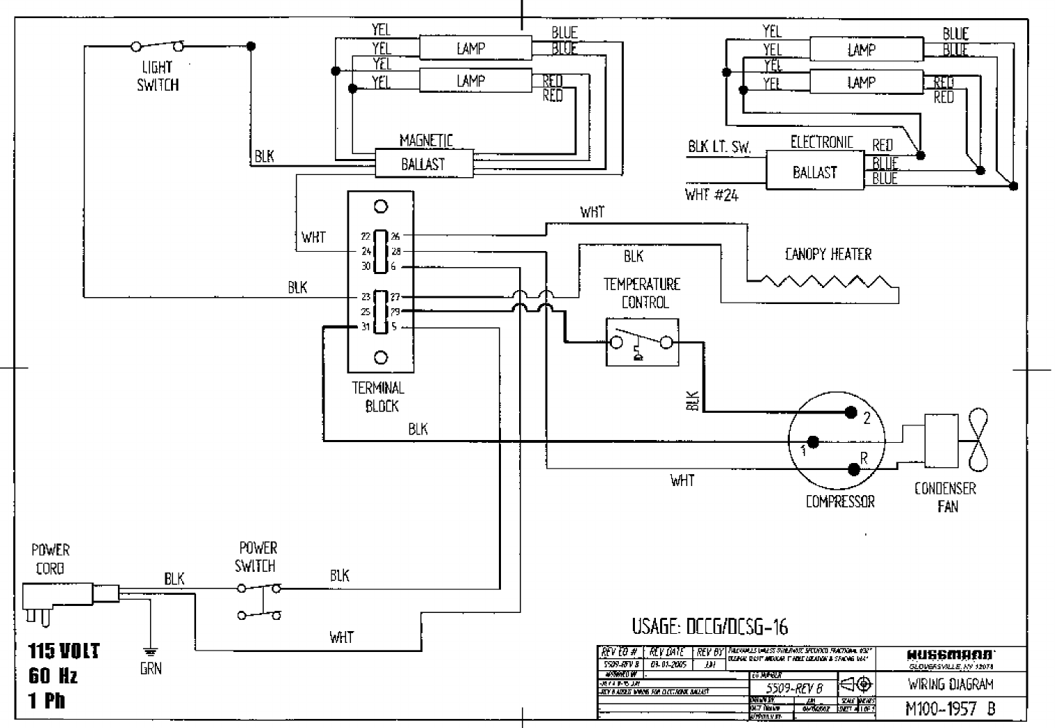
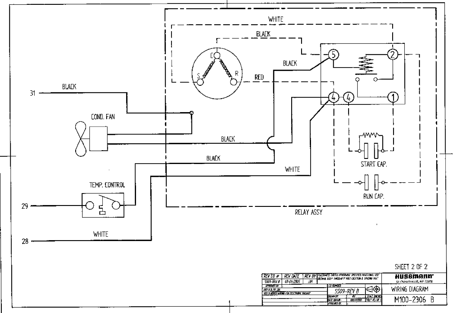
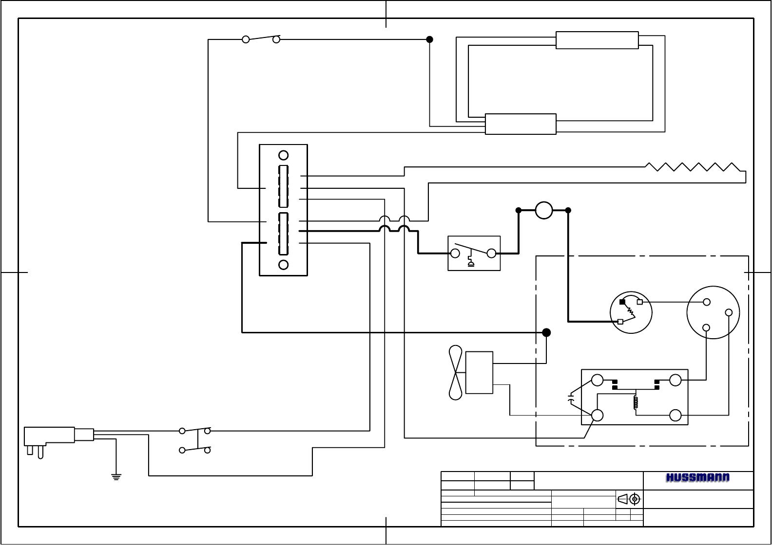
M100-2309
WIRING DIAGRAM
GLOVERSVILLE, NY 12078
REV EO # REV DATE REV BY
APPROVED BY EO NUMBER
SCALE
SHEET #
DRAWN BY:
DATE DRAWN :
APPROVED BY:
-
JJH
01/29/2004
-
INCHES
1 OF 1
--
-
-
-
-
-
-
-
TOLERANCES UNLESS OTHERWISE SPECIFIED: FRACTIONAL 1/32"
DECIMAL 0.031" ANGULAR 1° HOLE LOCATION & SPACING 1/64"
22 26
24 28
30 6
23 27
25 29
31 5
CR
S
1
2
S
M
START
CAP.
RELAY
OVERLOAD
COMPRESSOR
MOTOR
COMPRESSOR
TEMPERATURE
CONTROL
CONDENSER
FAN
LAMP
BALLAST
LIGHT
SWITCH
TERMINAL
BLOCK
POWER
SWITCH
POWER
CORD
BLUE
BLUE
RED
RED
BLK
WHT
BLK
BLK
WHT
BLK
GRN
115 VOLT
60 Hz
1 Ph
BLK
WHT
USAGE: DCCG-4
WHT
BLK
CANOPY HEATER
HIGH LIMIT SWITCH
