Hustler Turf Fastrak 36 And 42 Decks Users Manual
!! Hustler-25 Hustler Turf Lawn Mower Manuals - Lawn Mower Manuals – The Best Lawn Mower Manuals Collection
to the manual 028a5c1a-1af3-4197-b33d-f43723840e9d
2015-02-09
: Hustler-Turf Hustler-Turf-Fastrak-36-And-42-Decks--Users-Manual-565994 hustler-turf-fastrak-36-and-42-decks--users-manual-565994 hustler-turf pdf
Open the PDF directly: View PDF ![]() .
.
Page Count: 98

•••••••
Hustler Turf Equipment
•••••
P.O. Box 7000
•••
Hesston, Kansas
•
67062-2097
Hustler FasTrak
36" & 42" Decks
Parts Manual

cl-2 333559 9/08
IMPORTANT: This engine is not equipped with a spark arrester muffler. It is a violation of California Public Resource Code
Section 4442 to use or operate this engine on any forest-covered, brush-covered, or grass-covered unimproved land. Other
states or federal areas may have similar laws.
This spark ignition system complies with Canadian ICES-002.
The Engine Owner’s Manual provides information regarding the U.S. Environmental Protection Agency (EPA) and the
California Emission Control Regulation of emission systems, maintenance and warranty.
Keep Engine Owner’s Manual with your unit. Should the Engine Owner’s Manual become damaged or illegible, re-
place immediately. Replacements may be ordered per the information found in the Product Information section of the
owner’s manual.
The engine exhaust from this product
contains chemicals known to the State
of California to cause cancer, birth
defects or other reproductive harm.
WARNING:

333559 9/08 cl-3

cl-4 333559 9/08

333559 09/08 c-1
Table of Contents
Chapter 1
General Information . . . . . . . . . . . . . . . . . . . . . . . . . . . . . . . . . . . . 1-1
Chapter 2
Tractor Frame Rivet Nut Installation . . . . . . . . . . . . . . . . . . . . . . . . 2-2
Engine Guard and Anti-rollover Bracket Assemblies . . . . . . . . . . . 2-3
Footrest Assembly . . . . . . . . . . . . . . . . . . . . . . . . . . . . . . . . . . . . . 2-4
Chapter 3
Battery Installation. . . . . . . . . . . . . . . . . . . . . . . . . . . . . . . . . . . . . . 3-2
Deck Lift Assembly . . . . . . . . . . . . . . . . . . . . . . . . . . . . . . . . . . . . . 3-3
Hydro Transmission Installation S/N Prior To 07091558 . . . . . . . . 3-4
Hydro Transmission Installation S/N Higher Than 07091558 . . . . . 3-6
Steering and Brake Assembly. . . . . . . . . . . . . . . . . . . . . . . . . . . . . 3-8
Chapter 4
Honda 16 HP Engine Installation . . . . . . . . . . . . . . . . . . . . . . . . . . 4-2
Kohler 15 & 17 HP Engine Installation . . . . . . . . . . . . . . . . . . . . . . 4-6
Fuel System Installation . . . . . . . . . . . . . . . . . . . . . . . . . . . . . . . . . 4-10
Instrument Panel Installation. . . . . . . . . . . . . . . . . . . . . . . . . . . . . . 4-12
Honda 16HP Electrical Schematic (793083). . . . . . . . . . . . . . . . . . 4-14
Kohler 15 & 17 HP Electrical Schematic (601127& 793117) . . . . . 4-16
Chapter 5
Front Wheel Assembly . . . . . . . . . . . . . . . . . . . . . . . . . . . . . . . . . . 5-2
Front Wheel Breakdown -768044 . . . . . . . . . . . . . . . . . . . . . . . . . . 5-3
Drive Wheel Assembly . . . . . . . . . . . . . . . . . . . . . . . . . . . . . . . . . . 5-4
Chapter 6
Deck Assembly 36". . . . . . . . . . . . . . . . . . . . . . . . . . . . . . . . . . . . . 6-2
Deck Pulley Assembly 36" . . . . . . . . . . . . . . . . . . . . . . . . . . . . . . . 6-4
Deck Assembly 42". . . . . . . . . . . . . . . . . . . . . . . . . . . . . . . . . . . . . 6-8
Deck Pulley Assembly 42" . . . . . . . . . . . . . . . . . . . . . . . . . . . . . . . 6-10
Blade Spindle Assembly Breakdown . . . . . . . . . . . . . . . . . . . . . . . 6-14
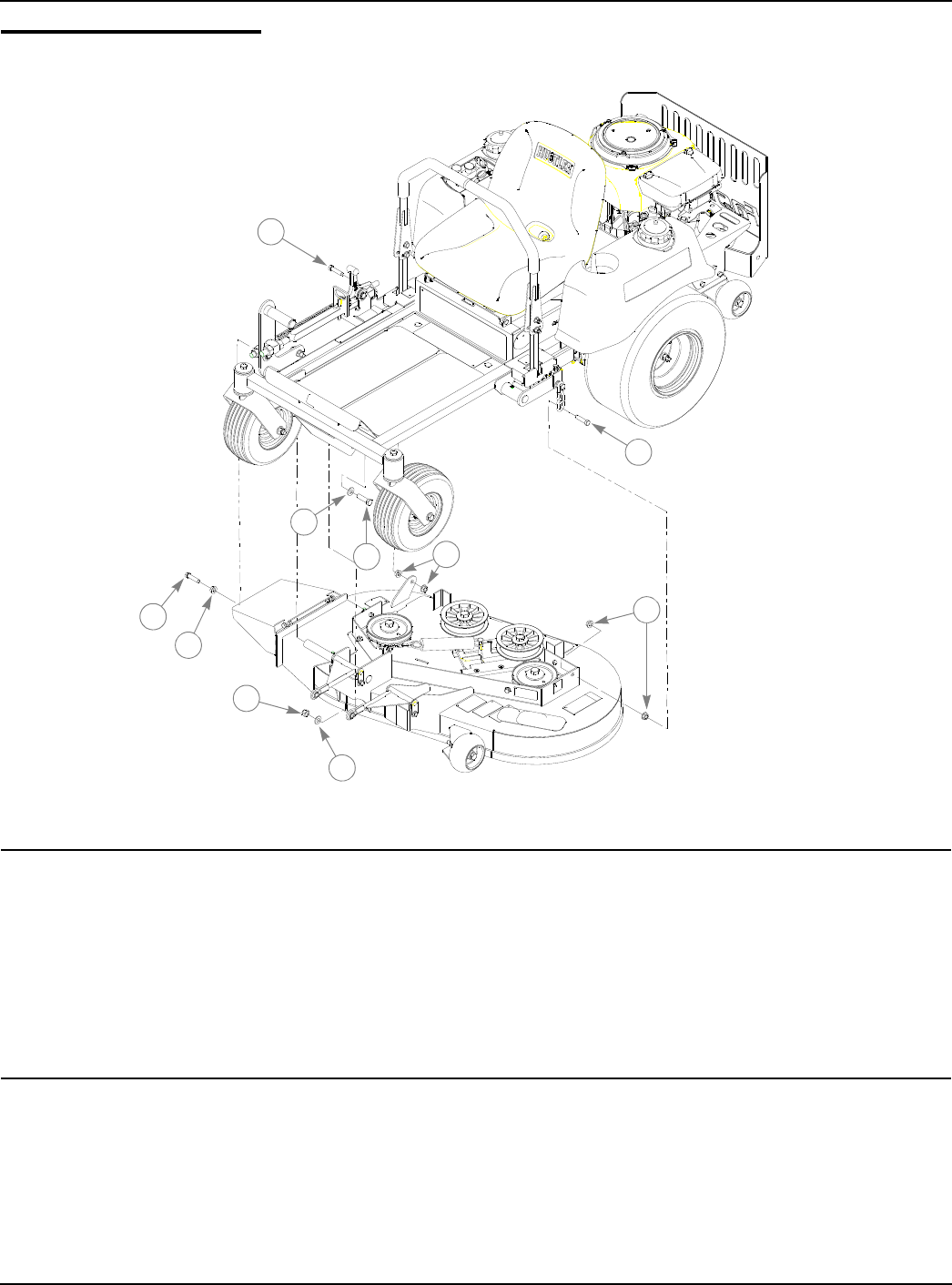
Chapter 7
Deck Installation . . . . . . . . . . . . . . . . . . . . . . . . . . . . . . . . . . . . . . . 7-2
Belt Routing and Tensioning. . . . . . . . . . . . . . . . . . . . . . . . . . . . . . 7-3
Seat Installation. . . . . . . . . . . . . . . . . . . . . . . . . . . . . . . . . . . . . . . . 7-4
Chapter 8
Tractor Decals. . . . . . . . . . . . . . . . . . . . . . . . . . . . . . . . . . . . . . . . . 8-2
42" Deck Decals . . . . . . . . . . . . . . . . . . . . . . . . . . . . . . . . . . . . . . . 8-4
36" Deck Decals . . . . . . . . . . . . . . . . . . . . . . . . . . . . . . . . . . . . . . . 8-5
Chapter 9
Maintenance & Adjustment Safety . . . . . . . . . . . . . . . . . . . . . . . . . 9-2
Maintenance . . . . . . . . . . . . . . . . . . . . . . . . . . . . . . . . . . . . . . . . . . 9-7
Adjustments . . . . . . . . . . . . . . . . . . . . . . . . . . . . . . . . . . . . . . . . . . 9-20
Index . . . . . . . . . . . . . . . . . . . . . . . . . . . . . . . . . . . . . . . . . . . . . . . . . . . . . . . . i-1

c-2 333559 09/08

333559 09/08 1-1
Chapter 1
General Information
This Manual covers “Mini” FasTrak 15/36 model 927343, “Mini” FasTrak 17/42 model 927350,
“Mini” FasTrak 16/42 model 927368, & “Mini” FasTrak 16/36 model 927376,
Frequently Ordered Parts
Service Literature
Options
Note: When ordering parts, you must use the part number as shown for each part, not the index number. Always give
the model and serial number to your parts and service representative.
Note: Items sold in bulk such as seals and hoses are sold by the foot.
Using this manual
Illustrations used were current at the time of printing, but subsequent production changes may cause your machine to
vary slightly in detail. Excel Industries, Inc. reserves the right to redesign and change the machine as deemed neces-
sary, without notification. If a change has been made to your machine which is not reflected in this parts manual, see
your Hustler dealer for current information and parts.
PART NO. DESCRIPTION
793836 Pump Drive Belt
793828 Deck Belt 36"
793893 Deck Belt 42"
068478 Fuel Filter Kohler
785626 Fuel Filter Honda
794370 Air Filter, Kohler
787226 Air Filter, Honda
747303 Engine Oil Filter, Kohler
787234 Engine Oil Filter, Honda
793794 20.50" 42D X 0.631 CW Blade
793802 13.75" 42D X 0.631 CW Blade
PART NO. DESCRIPTION
601156 Owners Manual
794313 Kohler Engine Manual
787242 Honda 16 HP Engine Manual
PART NO. DESCRIPTION
793331 Armrest Kit
338442 Mulch Kit, 36/42"

1-2 333559 09/08
Hardware Description Codes & Abbreviations
The following codes are used throughout this parts manual. Refer to this list when ordering parts.
Standard Torques
The following chart lists the standard torque values for the threaded fasteners found in this manual. Torque all cap
screws, nuts and set screws to these values unless a different torque is shown in the Notes section next to the fastener
NOTE:
Loctite 592 to be used on all pipe threads.
Lubricate all grease zerks.
ABBREVIATION DESCRIPTION
CB Carriage Bolt
CE Clevis Pin
CP Cotter Pin
CS Cap Screw
CW Cup Washer
FDRW Fender Washer
FW Flat Washer
HX Hex Head
LW Lock Washer
MB Machine Bushing
MS Machine Screw
NT Nut
SC Self Tapping Cap Screw
SH Socket Head
SB Shoulder Bolt
SS Set Screw
OD Outside Diameter
ID Inside Diameter
SIZE FT-LBS NM SIZE FT-LBS NM
.250 8.2 11.1 M3 1 1.3
.312 17 23 M4 2.2 3
.375 30 40 M5 4.5 6.1
.438 48 65 M6 7.7 10.4
.500 73 99 M8 18.5 25
.562 105 143 M10 37 50
.625 145 200 M12 64 87
.750 260 350 M16 160 215
.875 420 565 M20 320 435
1.00 625 850 M24 555 750

333559 09/08 2-1
Chapter 2 Contents
Tractor Frame Rivet Nut Installation . . . . . . . . . . . . . . . . . . . . . . . . . 2-2
Engine Guard and Anti-rollover Bracket Assemblies. . . . . . . . . . . . . 2-3
Footrest Assembly. . . . . . . . . . . . . . . . . . . . . . . . . . . . . . . . . . . . . . . 2-4
2-2 333559 09/08
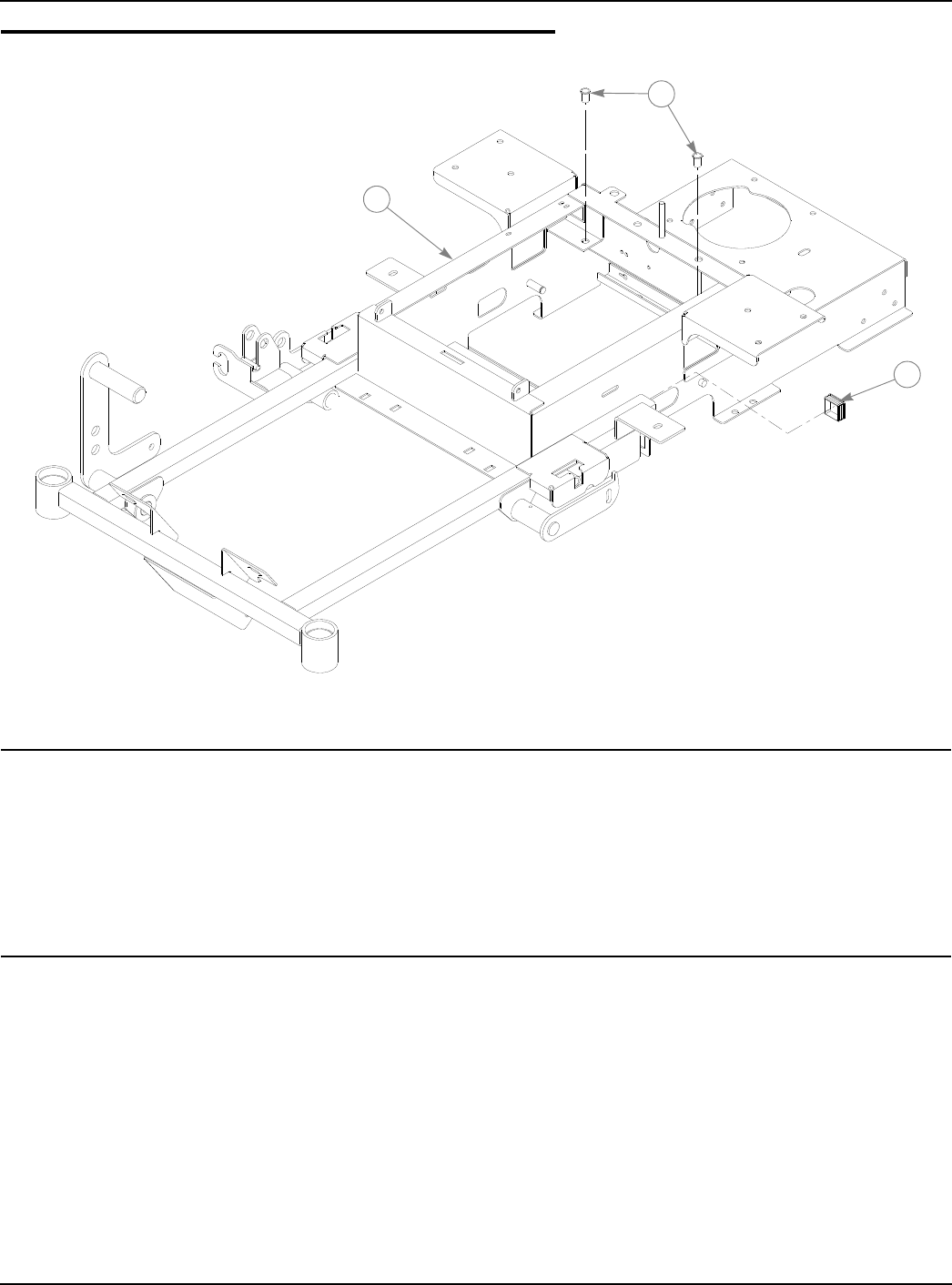
Tractor Frame Rivet Nut Installation
NOTES:
INDEX
NO. SERVICE
PART NO. MFG. PART
NO. QTY. DESCRIPTION
1 546911 315440 1 FASTRAK 36 FRAME
546895 320242 1 FASTRAK 42 FRAME
2 808493 808493 2 3/8-16 THREAD RIVET NUT
3 793869 793869 2 1.5 SQ TUBE PLUG
2
1
3
333559 09/08 2-3
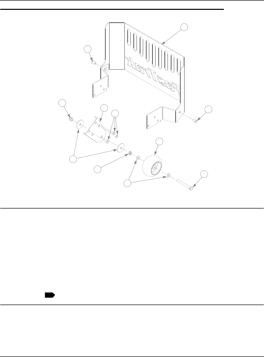
Engine Guard and Anti-rollover Bracket Assemblies
NOTES:
1. Includes items 6 through 9.
INDEX
NO. SERVICE
PART NO. MFG. PART
NO. QTY. DESCRIPTION
1 316836 316836 1 ENGINE GUARD
2 320580 320580 2 ANTI ROLLOVER BRACKET
3 808493 808493 8 3/8-16 THREAD RIVET NUT
4 781567 781567 2 NT .50-13 HX LK NY ZNYC
5 344267 344267 4 FW .510 X 2.15 X .187SPL ZNYC
6 053199 N/A 2 NT .500-13 HX JAM ZNYC
7 767962 N/A 4 FW .531 X 1.063 X .090 SAE HD ZN
8 031997 N/A 2 ANTI-SCALP WHEEL
9 781708 N/A 2 CS .500-13 X 4.25 HX G5 ZNYC
10 788166 788166 2 ANTI SCALP WHEEL ASSEMBLY
1
3
3
23
4
5
7
8
9
6
1
2-4 333559 09/08
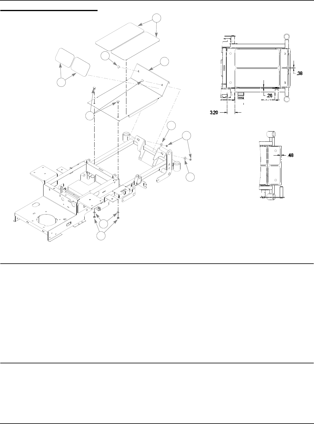
Footrest Assembly
NOTES:
INDEX
NO. SERVICE
PART NO. MFG. PART
NO. QTY. DESCRIPTION
1 011320 011320 4 CB .375-16 X .75 STD ZN
2 785485 785485 2 UPPER STEP TREAD
3 793844 793844 2 LOWER STEP TREAD
4 320267 320267 1 FLOOR PLATE 36" MOWERS
316844 316844 1 FLOOR PLATE 42" MOWERS
5 767954 767954 2 FW .406 X .812 X .060 SAE HD ZN
6 076422 076422 2 FW.406X 1.000X.06 ZNYC
7 054502 054502 4 NT .375-16 HX GRD 5 ZNYC
1
2
3
4
1
7
6
5
7
6

333559 09/08 3-1
Chapter 3 Contents
Battery Installation . . . . . . . . . . . . . . . . . . . . . . . . . . . . . . . . . . . . . . . 3-2
Deck Lift Assembly . . . . . . . . . . . . . . . . . . . . . . . . . . . . . . . . . . . . . . 3-3
Hydro Transmission Installation S/N Prior To 07091558. . . . . . . . . . 3-4
Hydro Transmission Installation S/N Higher Than 07091558 . . . . . . 3-6
Steering and Brake Assembly . . . . . . . . . . . . . . . . . . . . . . . . . . . . . . 3-8

3-2 333559 09/08
Battery Installation
NOTES:
INDEX
NO. SERVICE
PART NO. MFG. PART
NO. QTY. DESCRIPTION
1 314989 314989 1 BATTERY CLAMP STRAP
2 024927 024927 3 NT .250-20 HX GR.5 ZNYC
3 055939 055939 2 CS .250-20 X .75 HX G5 ZNYC
4 029868 029868 4 LW .250 INT-EXT TOOTH ZNYC
5 740696 740696 1 BATTERY VU1LH-8
6 771428 771428 1 RED BATTERY CABLE BOOT
7 785063 785063 1 POSITIVE BATTERY CABLE (KOHLER)
786632 786632 1 POSITIVE BATTERY CABLE (HONDA)
8 786640 786640 1 NEGATIVE BATTERY CABLE
9 793489 793489 1 BATTERY CLAMP ROD
12
2
2
3
3
4
4
6
5
78
9
PART OF WIRE
HARNESS (BLK)
4
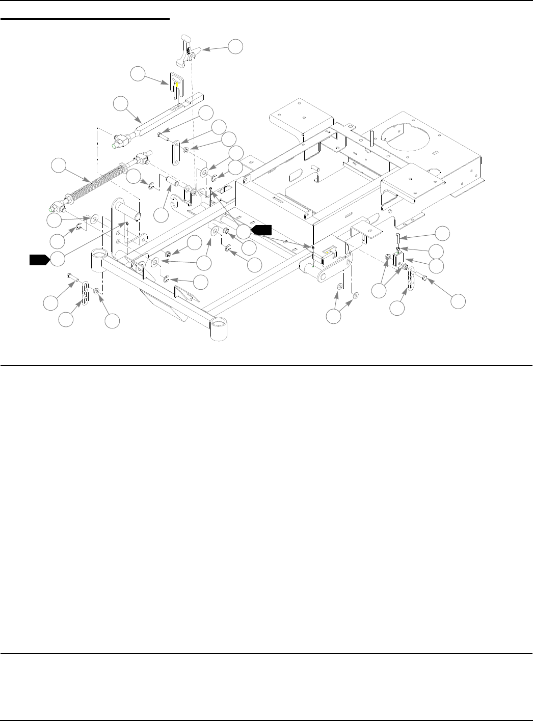
333559 09/08 3-3
Deck Lift Assembly
NOTES:
1. Apply grease to zerks (see owners manual).
INDEX
NO. SERVICE
PART NO. MFG. PART
NO. QTY. DESCRIPTION
1 348318 348318 1 STOP HANDLE
2 348284 348284 1 HEIGHT ADJUSTMENT STOP
3 793505 793505 1 DECK HEIGHT INDICATOR
4 782995 782995 1 DECK LIFT SPRING
5 055749 055749 2 CS .437-14 X 1.75 HX G5 ZNYC
6 334045 334045 1 DECK LIFT LINK
7 704643 704643 6 NT .437-14 HX FLG ZN
8 025296 025296 4 FW .760 X 1.625 X .08 ZNYC
9 781294 781294 5 E CLIP 1.00 X.625X .050
10 781229 781229 1 CE .750 X 2.25 X 1.75 HEADLESS
11 015495 015495 3 STRAIGHT GREASE FITTING
12 756270 756270 1 CS .312-18 X 1.50 FLTHR GR5 ZNYC
13 034272 034272 1 NT .312-18 HX G5 ZNYC
14 348458 348458 1 DECK LEVELER YOKE
15 781831 781831 1 CS .437-14 X 1.75 FULTH G5 ZNYC
16 360131 018846 2 DECK LIFTCHAIN
17 767962 767962 2 FW .531 X 1.063 X .090 SAE HD ZN
1
1
2
3
4
5
67
7
77
8
8
9
9
9
9
9
10
8
11
12
13
16
16
15
5
14
17
1
11
7
3-4 333559 09/08
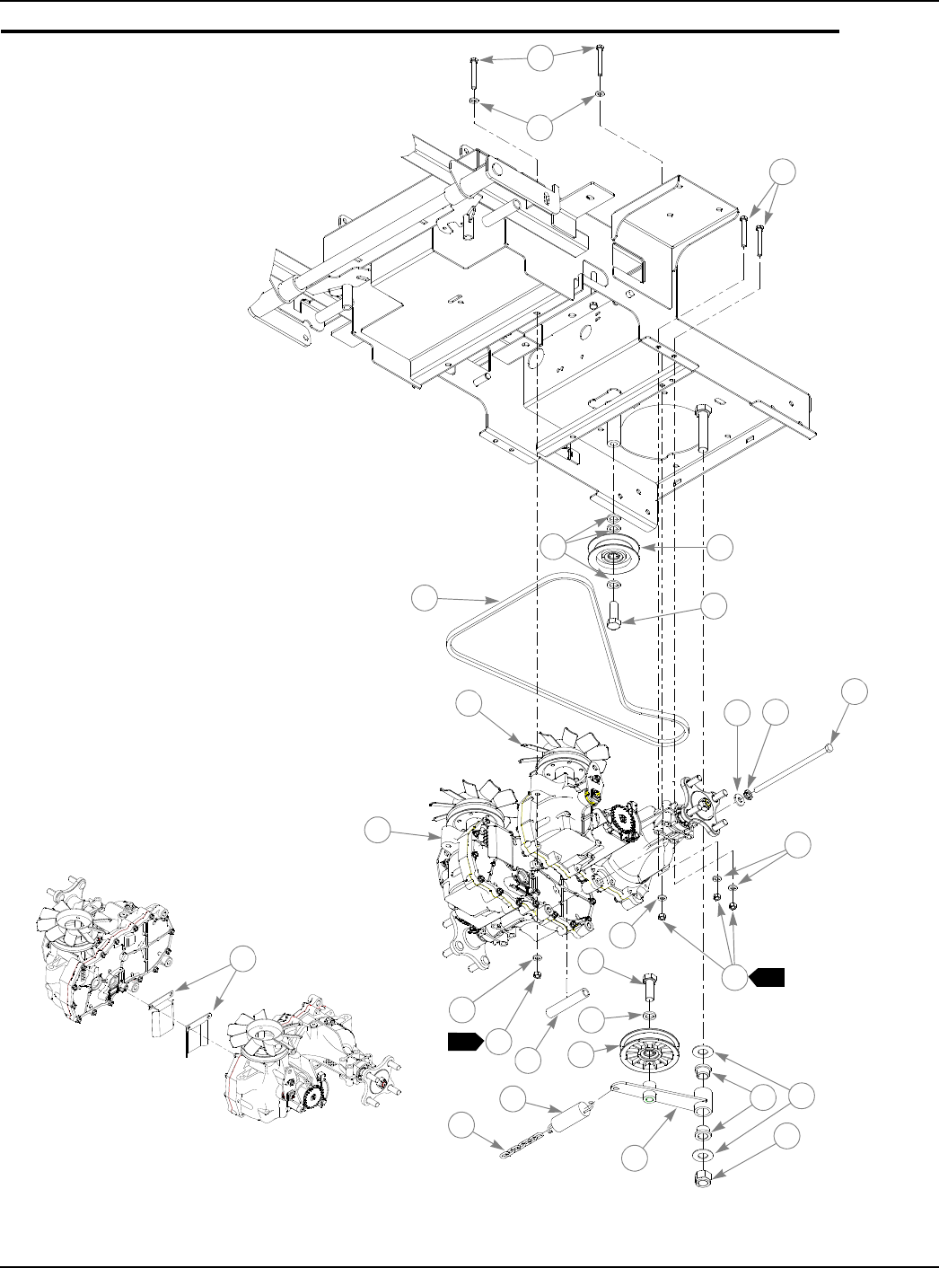
Hydro Transmission Installation S/N Prior To 07091558
3
4
5
7
6
1
1
12
12
13
13
4
2
14
12
15 16
18
19
20
17
12
11
810
21
1
1
2
9

333559 09/08 3-5
Hydro Transmission Installation S/N Prior To 07091558
NOTES:
1. Torque to 17 ft.-lbs.
2. Install using existing hardware on EZT.
3. Do not torque, item 17 (Pump Belt Idler Arm) must pivot freely.
4. Hydro transmission service parts:
INDEX
NO. SERVICE
PART NO. MFG. PART
NO. QTY. DESCRIPTION
1 710087 710087 8 CS .312-18 X 2.50 HX G5 ZNYC
2 028118 028118 2 FW .62 X 1.00 X .134 ZNYC
3 794404 794404 1 PULLEY
4 025007 025007 2 CS .625-11 X 1.75 HX G5 ZNYC
5 793836 793836 1 A-SECTION PUMP BELT
6 792911 792911 1 EZT LEFT PUMP/MOTOR COMBO
7 792895 792895 1 EZT RIGHT PUMP/MOTOR COMBO
8 718288 718288 1 FW .516 X .875 X .09 ZNYC
9 035238 035238 1 LW .437 MED SPRING ZYNC
10 794552 794552 1 NT .375-16 HXZY NL
11 335695 335695 1 SPACER TUBE-EZT MINI FST
12 768523 768523 12 FW .343 X .687 X .051/.080 HD ZNYC
13 034272 034272 8 NT .312-18 HX G5 ZNYC
14 784827 784827 1 4.00"OD, 5/8"ID IDLER PULLEY
15 781153 781153 2 UHMW BUSHING
16 025296 025296 2 FW .760 X 1.625 X .08 ZNYC
17 324046 324046 1 PUMP BELT IDLER ARM
18 061101 061101 1 NT .750-10 HX NL ZN
19 036384 036384 1 IDLER SPRING
20 364315 059931 1 SPRING CHAIN
21 335893 335893 2 BELT DEFLECTOR
PART NUMBER
PRIOR TO
SERIAL NUMBER
06081543
DESCRIPTION PART NUMBER
SERIAL NUMBER
06081543 DESCRIPTION
792013 AXLE NUT 788877 AXLE NUT
794982 FAN, EZT 794974 EZT PULLEY KIT
795005 RIGHT EZ CAP-VENT ASSY 795039 LEFT EZ VENT TUBE ASSY
795013 EZT NUT, SPECIAL 791723f FW .530 X 1.63 X .06 SLO
795021 HUB ASSEMBLY 788232 HUB ASSEMBLY
795047 PARKING PAWL KIT, EZT 798363 PARKING BRAKE GEAR
795054 90 DEG VENT FITTING 795062 RIGJHT EZT VENT HOSE
798371 RETAINING RING 792929 PULLEY/FAN COMBO 36/42
3
3-6 333559 09/08
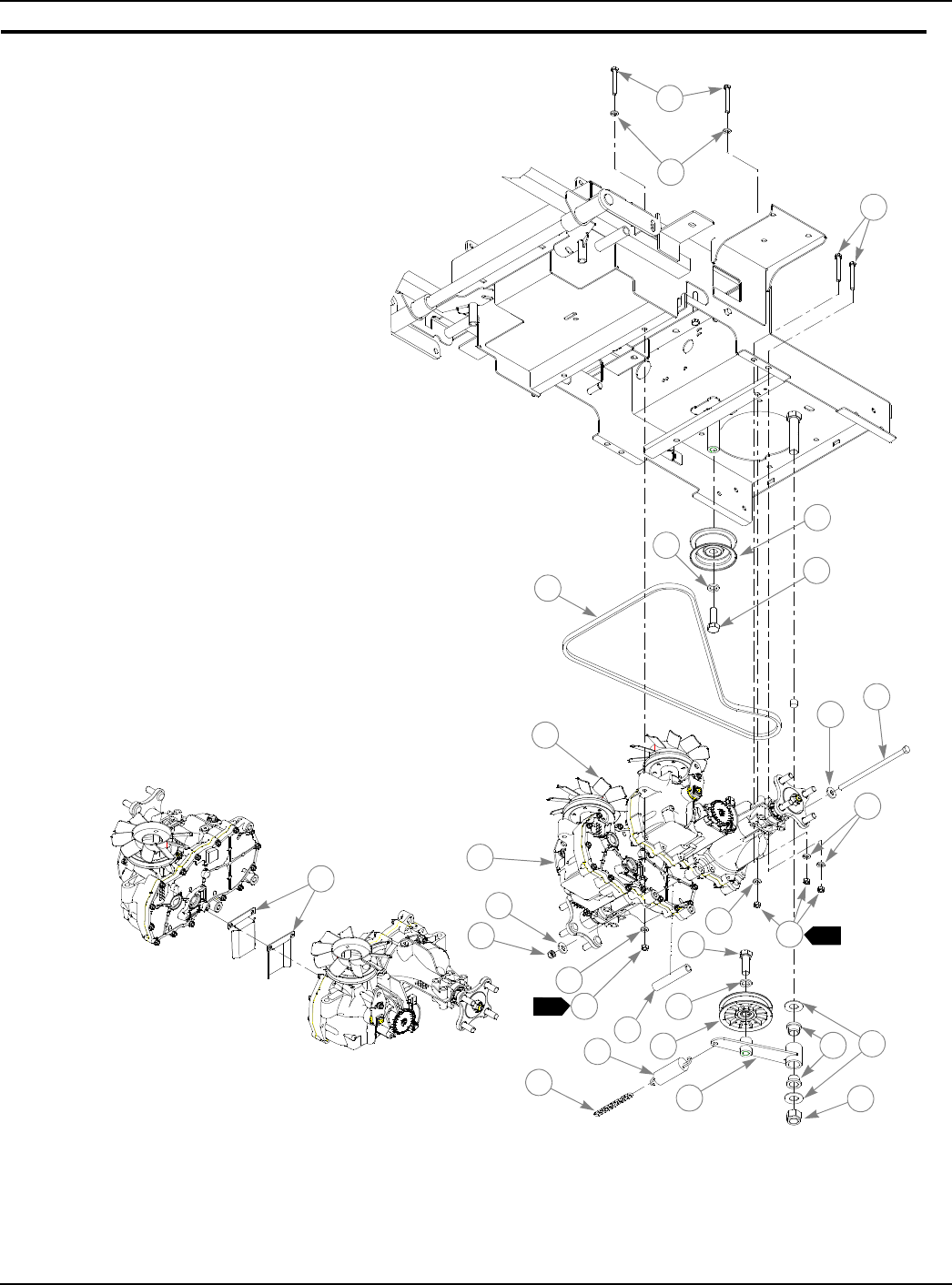
Hydro Transmission Installation S/N Higher Than 07091558
3
4
5
7
6
1
1
11
11 12
12
4
2
13
11
14 15
17
18
19 16
11
10
89
20
1
1
2
8
21

333559 09/08 3-7
Hydro Transmission Installation S/N Higher Than 07091558
NOTES:
1. Torque to 17 ft.-lbs.
2. Hydro transmission service parts:
INDEX
NO. SERVICE
PART NO. MFG. PART
NO. QTY. DESCRIPTION
1 710087 710087 8 CS .312-18 X 2.50 HX G5 ZNYC
2 028118 028118 2 FW .62 X 1.00 X .134 ZNYC
3 601162 601162 1 PULLEY
4 025007 025007 2 CS .625-11 X 1.75 HX G5 ZNYC
5 793836 793836 1 A-SECTION PUMP BELT
6 792911 792911 1 EZT LEFT PUMP/MOTOR COMBO
7 792895 792895 1 EZT RIGHT PUMP/MOTOR COMBO
8 712919 712919 2 FW .516 X .875 X .09 ZNYC
9 721134 721134 1 CS .375-16X8.0 HX.GR5 Z
10 335695 335695 1 SPACER TUBE-EZT MINI FST
11 768523 768523 12 FW .343 X .687 X .051/.080 HD ZNYC
12 034272 034272 8 NT .312-18 HX G5 ZNYC
13 784827 784827 1 4.00"OD, 5/8"ID IDLER PULLEY
14 781153 781153 2 UHMW BUSHING
15 025296 025296 2 FW .760 X 1.625 X .08 ZNYC
16 324046 324046 1 PUMP BELT IDLER ARM
17 061101 061101 1 NT .750-10 HX NL ZN
18 036384 036384 1 IDLER SPRING
19 364315 059931 1 SPRING CHAIN
20 335893 335893 2 BELT DEFLECTOR
21 086660 086660 1 NT .375-16 HXZY NL
PART NUMBER
PRIOR TO
SERIAL NUMBER
06081543
DESCRIPTION PART NUMBER
SERIAL NUMBER
06081543 DESCRIPTION
792013 AXLE NUT 788877 AXLE NUT
794982 FAN, EZT 794974 EZT PULLEY KIT
795005 RIGHT EZ CAP-VENT ASSY 795039 LEFT EZ VENT TUBE ASSY
795013 EZT NUT, SPECIAL 791723f FW .530 X 1.63 X .06 SLO
795021 HUB ASSEMBLY 788232 HUB ASSEMBLY
795047 PARKI NG PAWL KIT, EZT 798363 PARKING BRAKE GEAR
795054 90 DEG VENT FITTING 795062 RIGJHT EZT VENT HOSE
798371 RETAINING RING 792929 PULLEY/FAN COMBO 36/42
3-8 333559 09/08
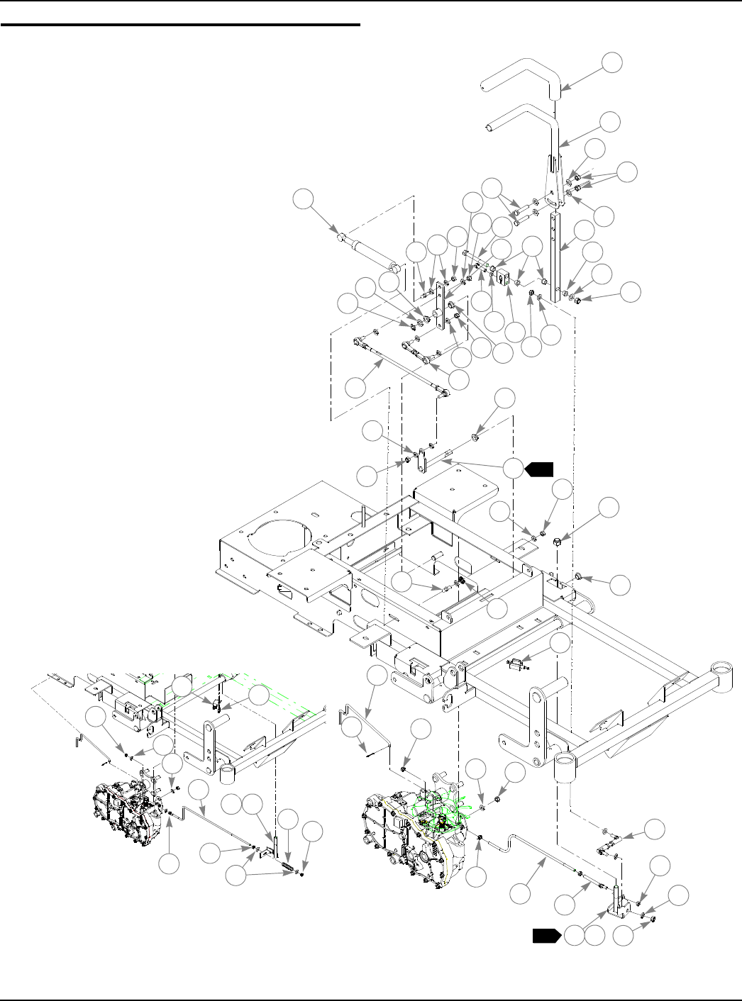
Steering and Brake Assembly
2
1
3
4
4
5
6
7
8
9
9
11
11
8
8
13
13
14
15
16
8
11
17
18
19
20
21
8
5
7
22 23
23
24
25
26
28
811
12
28
13
29 30
31 11
32
33
8
4
11
10
10
8
27
2
3
13
41
28
21
8
39 36 37 38 27
27
20 40
See Note 4
35 35

333559 09/08 3-9
Steering and Brake Assembly
NOTES:
1. To adjust park brake safety switch: with Steering Bars in park position,
adjust item 24 (795625 Snap Mount Plunger Switch) outboard until
INDEX
NO. SERVICE
PART NO. MFG. PART
NO. QTY. DESCRIPTION
1 781260 N/A 2 STEERING BAR GRIP
2 360487 360487 2 STEERING BAR
3 600221 600221 2 CENTERING DAMPER
783696 783696 2 CENTERING DAMPER
4 767954 767954 10 FW .406 X .812 X .060 SAE HD ZN
5 086660 086660 6 NT .375-16 HX LK NY
6 705178 705178 4 CS .375-16 X 1.75 HX G5 ZNYC
7 034272 034272 4 NT .312-18 HX G5 ZNYC
8 768523 768523 22 FW .343 X .687 X .051/.080 HD ZNYC
9 781922 781922 4 DAMPER BALL STUD
10 797779 797779 8 IGUS® BUSHING
11 023655 023655 12 NT .312-24 HX ZNYC
12 325464 325464 2 STEERING CONTROL ARM
13 768259 768259 8 IGUS® BUSHING
14 718288 718288 2 FW .516 X .875 X .09 ZNYC
15 793059 793059 2 E CLIP .80X.396X.042
16 793646 793646 2 PUMP ROD ADJUSTER ASSEMBLY
17 794396 794396 2 STEERING LINK ROD
18 793612 793612 2 STEERING DRIVE ARM
19 797753 797753 2 STEERING ARM
20 005108 005108 2 CS .375-16 X 3.50 HX G5
21 079186 079186 2 CS .312-18 X 1.25 HX G5 ZNYC
22 797761 797761 2 STEERING BLOCK
23 781567 781567 2 NT .50-13 HX LK NY ZNYC
24 795625 795625 2 SNAP MOUNT PLUNGER SWITCH
25 796615 796615 2 BALL JOINT LINK
26 793174 793174 2 TOWLINK ROD
27 048553 048553 2 CP .062D X 1.00 LG HML ZN
28 068551 068551 4 NT .250-20 HX NL ZNYC
29 797050 797050 2 BRAKE ACTUATOR ROD
30 795229 795229 2 INLINE BALL JOINT
31 352112 352112 1 L. H. BRAKE PIVOT (SHOWN)
32 352054 352054 1 R. H. BRAKE PIVOT (NOT SHOWN)
33 024927 024927 2 NT .250-20 HX GR.5 ZNYC
34 781211 781211 2 PUSH BUTTON SWITCH, (DELTA)
35 060731 060731 4 CS 10-24 X .500 HXFLK ZNYC
36 315382 N/A 1 LEFT BRAKE PIVOT ARM (SHOWN)
37 315101 N/A 1 RIGHT BRAKE PIVOT ARM (NOT SHOWN)
38 794883 794883 2 COMPRESSION SPRING
39 793182 793182 2 BRAKE ACTUATOR ROD
40 089789 089789 4 FW .266 X .750 X .06 ZNYC
41 029876 029876 2 LW .312 INT-EXT TOOTH Z
4
5
3
3
3
3
3
3
3

3-10 333559 09/08
switch is activated by items 31/32 (352112/352054 Brake Pivots).
2. Order these parts for mowers with serial number prior to 05040000.
3. Includes Item 1 (781260 Steering Bar Grip).
4. Use on mowers with serial numbers prior to 060171975.

333559 09/08 4-1
Chapter 4 Contents
Honda 16 HP Engine Installation. . . . . . . . . . . . . . . . . . . . . . . . . . . . 4-2
Kohler 15 & 17 HP Engine Installation. . . . . . . . . . . . . . . . . . . . . . . . 4-6
Fuel System Installation. . . . . . . . . . . . . . . . . . . . . . . . . . . . . . . . . . 4-10
Instrument Panel Installation . . . . . . . . . . . . . . . . . . . . . . . . . . . . . . 4-12
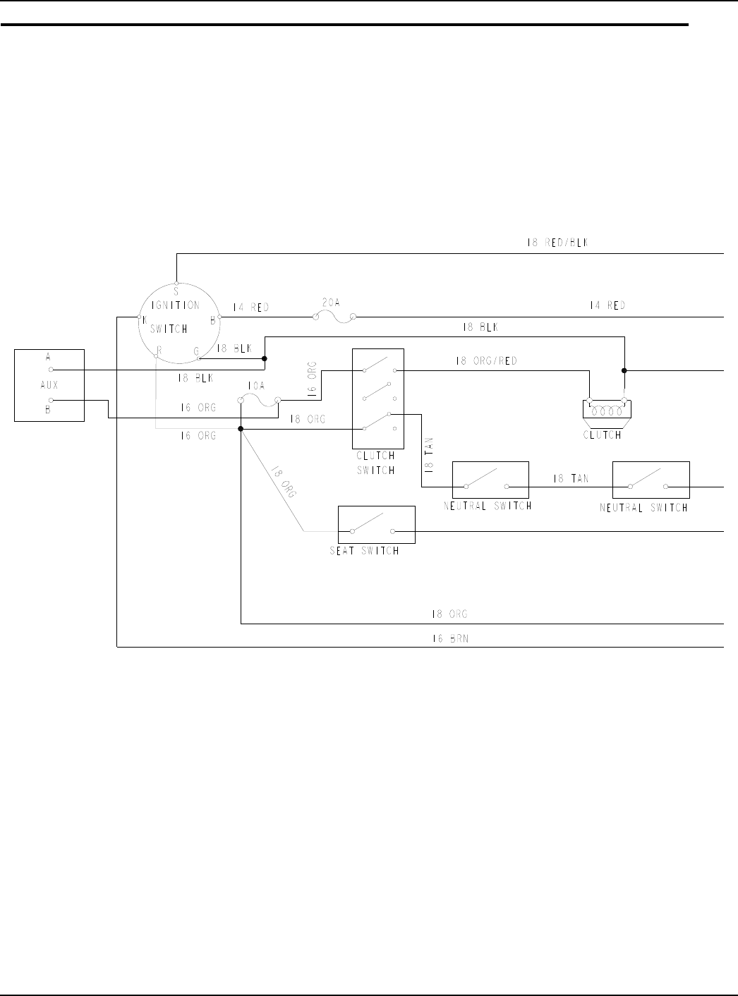
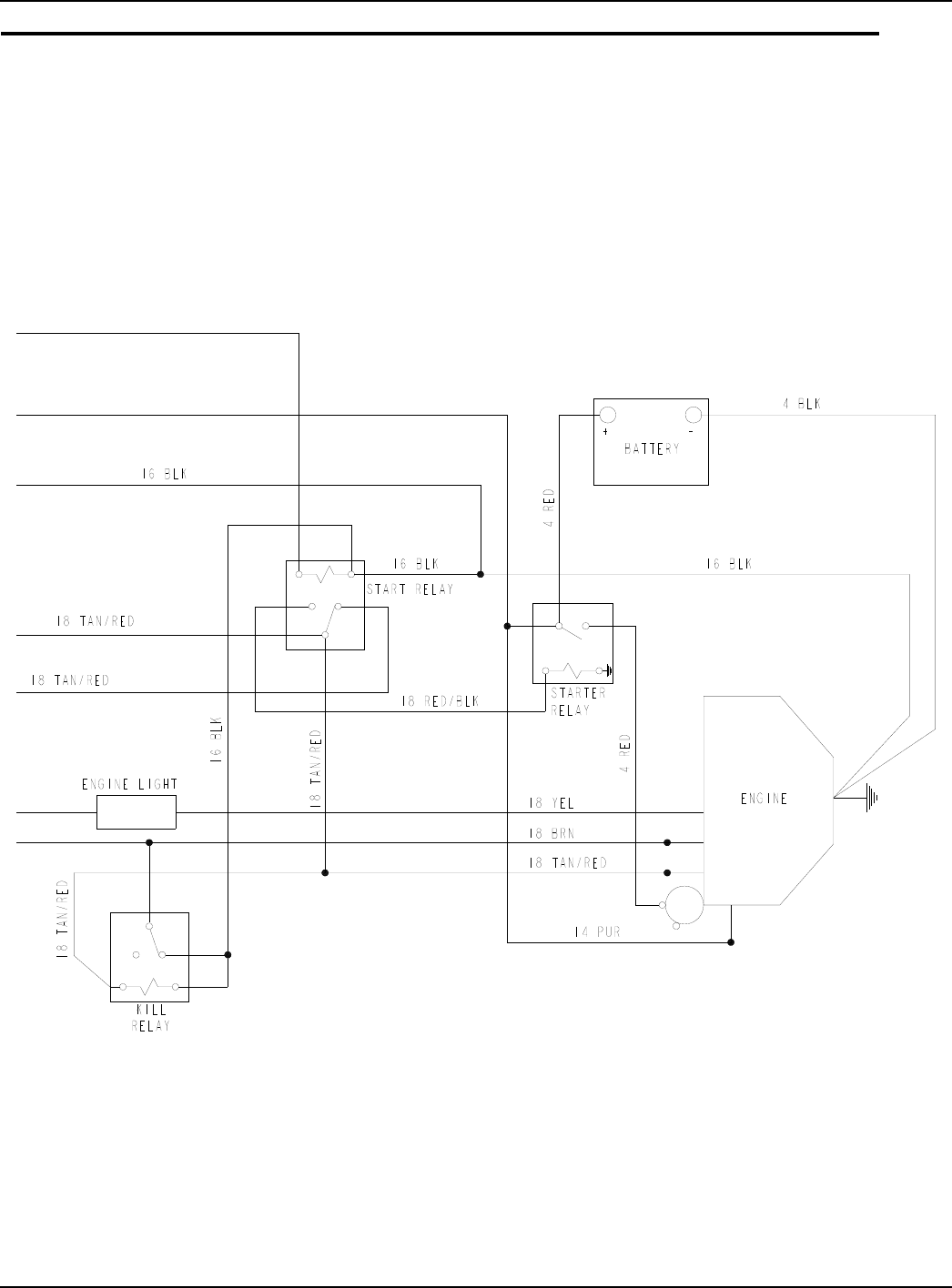
Honda 16HP Electrical Schematic (793083) . . . . . . . . . . . . . . . . . . 4-14
Kohler 15 & 17 HP Electrical Schematic (601127& 793117). . . . . . 4-16
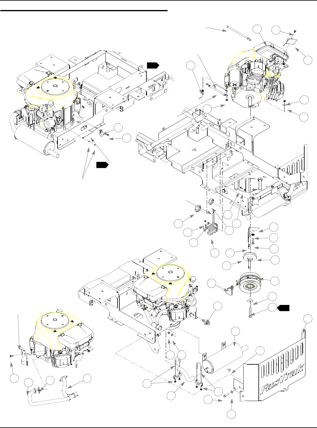
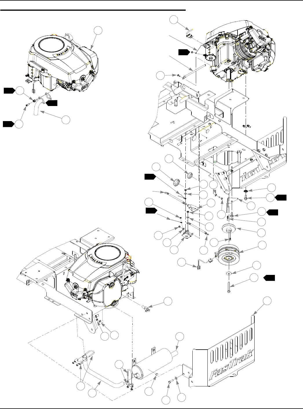
4-2 333559 09/08
Honda 16 HP Engine Installation
1
3
4
5
7
NEGATIVE
BATTERY
CABLE
POSITIVE
BATTERY
CABLE
1
1
RED/BLK
YEL
6
8
TO ENGINE
(4 WIRES)
10
12
8
913
14
15
17
19
21
22
16
20
18
425
32
26
27
29
28
36
34
35
23
PART OF
ENGINE
FROM
RECTIFIER
37
31
33
11
2
2
24
2
PART OF
ENGINE
30
4

333559 09/08 4-3
Honda 16 HP Engine Installation
INDEX
NO. SERVICE
PART NO. MFG.
PART NO. QTY. DESCRIPTION
1 785394 785394 1 HONDA 16HP ENGINE (USED ON 927368 &
927376)
2 739144 792796 3
3 378273 378273 1 16HP EXHAUST HEAT SHIELD
4 034272 034272 6 NT .312-18 HX G5 ZNYC
5 712927 712927 4 FW .344 X 1.00 X .12 HRD ZNYC
6 782664 782664 1 NT M8-1.25 HX STAINLESS STEEL
7 024927 024927 2 NT .250-20 HX GR.5 ZNYC
8 768515 768515 4 FW .281 X .625 X .051/.080 HD ZNYC
9 056077 056077 2 CS .250-20 X 1.00 HX G5 ZNYC
10 787267 N/A 1 HONDA 16 AMP RECTIFIER
11 794644 794644 1 GM 1.50 X 2.12 X 1.75 X .12
12 706531 706531 1 GM 1.12 X 1.75 X 1.37 X .12
13 330274 330274 1 CLUTCH ANCHOR
14 029876 029876 4 LW .312 INT-EXT TOOTH ZNYC
15 050161 050161 4 CS .312-18 X 1.75 HX G5 ZNYC
16 784918 784918 1 RUBBER BUMPER
17 793760 793760 1 ENGINE-HYDRO DRIVE PULLEY
18 712372 712372 1 KEY 1/4 SQ. X 0.66 LONG
19 601325 601325 1 WARNER CLUTCH
20 791251 N/A 1 CLUTCH WIRE HARNESS PIGTAIL
21 763417 763417 1 FW .454 X 1.50 X.250
22 785048 785048 1 CS .437-20 X 3.00 HX G5 ZNYC
23 043570 043570 1 SINGLE HOSE CLIP
24 791608 791608 1 OIL DRAIN VALVE, M16 X 1.5
25 768523 768523 2 FW .343 X .687 X .051/.080 HD ZNYC
26 793125 793125 1 MUFFLER 15,17 KOHLER & 16 HONDA
27 016253 016253 2 CB .312-18 X .750 FUL ZN
28 316836 316836 1 ENGINE GUARD
29 767954 767954 6 FW .406 X .812 X .060 SAE HD ZN
30 052860 052860 6 CS .375-16 X 1.25 HX G5 ZNYC
31 794180 794180 1 1.125" EXHAUST CLAMP
32 793166 793166 1 16 HONDA MID EXHAUST PIPE
33 794172 794172 1 1.25" EXHAUST CLAMP
34 793141 793141 1 16 HONDA MANIFOLD
35 005231 005231 4 NT M6-1.0-10 HX FLG ZN
36 785543 N/A 2 HONDA MUFFLER GASKET
37 793083 793083 1 HONDA WIRE HARNESS
38 104786 104786 1 OIL DRAIN HOSE (NOT SHOWN)

4-4 333559 09/08
NOTES:
1. Part of item (793083 Honda Wire Harness).
2. Engine oil capacity:See engine owner’s manual.
3. Engine speed; 3550±50 RPM.
4. Torque to 45-48 ft-lb.

333559 09/08 4-5
.This page intentionally left blank.
4-6 333559 09/08
Kohler 15 & 17 HP Engine Installation
1
12
1
5
1
TTO
TO STARTER
SOLENOID
6
7
6
7
67
11
12 13
7
14
15
16
17
18
19
20 21
22 23
24
25
30
29
28
32
27 26
34
RED/BLK
FROM NEGATIVE
BATTERY TEMINAL
33
33
35
2
2
RED
PUR
8
31
17
TO BATTERY
10
5
5
9
4
13
8

333559 09/08 4-7
Kohler 15 & 17 HP Engine Installation
NOTES:
INDEX
NO. SERVICE
PART NO. MFG.
PART NO. QTY. DESCRIPTION
1 792945 792945 1 KOHLER 15 HP ENGINE SV470S
792952 792952 1 KOHLER 17 HP ENGINE SV530S
2 793133 793133 1 KOHLER 15 & 17 HP EXHAUST MANIFOLD
3 017004 N/A 2 LW .312 MED SPRING ZNYC
4 704478 N/A 2 CS .312-18 X .75 SKTHD BO
5 739144 792796 1 CS M 6-1.0 X 12 10.9 HX
6 024927 024927 4 NT .250-20 HX GR 5 ZNYC
7 768515 768515 6 FW .281 X .625 X .051/.080 HD ZNYC
8 706531 706531 1 GM 1.12 X 1.75 X 1.37 X .12
9 794644 794644 1 GM 1.50 X 2.12 X 1.75 X .12
10 771428 771428 1 RED BATTERY CABLE BOOT
11 044255 044255 1 NT #10-32 HX ZN
12 030817 030817 1 STARTER SOLENOID
13 792762 792762 1 BATTERY CABLE
14 056077 056077 2 CS .250-20 X 1.00 HX G5 ZNYC
15 330274 330274 1 CLUTCH ANCHOR
16 793885 793885 1 LW .375 INT-EXT TOOTH
17 036244 792788 4 CS .375-16X1.000 HX G5
18 784918 784918 1 RUBBER BUMPER
19 793760 793760 1 ENGINE-HYDRO DRIVE PULLEY
20 712372 712372 1 KEY 1/4 SQ. X 0.66 LONG
21 601325 601325 1 WARNER CLUTCH
22 791251 N/A 1 CLUTCH WIRE HARNESS PIGTAIL
23 763417 763417 1 FW .454 X 1.50 X.250
24 785048 785048 1 CS .437-20 X 3.00 HX G5 ZNYC
25 316836 N/A 1 ENGINE GUARD
26 767954 767954 6 FW .406 X .812 X .060 SAE HD ZN
27 052860 052860 6 CS .375-16 X 1.25 HX G5 ZNYC
28 768523 768523 2 FW .343 X .687 X .051/.080 HD ZNYC
29 016253 016253 2 CB .312-18 X .750 FUL ZN
30 793125 793125 1 MUFFLER 15,17 KOHLER & 16 HONDA
31 796516 796516 1 3/8-18 OIL DRAIN VALVE
32 034272 034272 2 NT .312-18 HX G5 ZNYC
33 794180 794180 2 1.125" EXHAUST CLAMP
34 793158 793158 1 KOHLER 15 & 17 HP MID EXHAUST PIPE
35 793117 793117 1 KOHLER WIRE HARNESS
601127 601127 1 KOHLER WIRE HARNESS
7

4-8 333559 09/08
1. Supplied with engine.
2. Part of Kohler Wire Harness item 35 (601127-For S/N higher than
07011902; 793117-For S/N prior to 07011902).
3. Engine oil capacity: See engine owner’s manual.
4. Engine speed; 3600±50 RPM.
5. Torque to 33-37 ft.-lbs. Do not reuse factory installed screw when
performing service to mower requiring removal of engine, replace with
3/8-16 X 1.0 long grade 5 cap screw.
6. Used on mowers with serial numbers prior to 7020776.
7. Used on mowers with serial numbers after 7020776.
8. Torque to 45-48 ft-lb.

333559 09/08 4-9
This page intentionally left blank.
4-10 333559 09/08
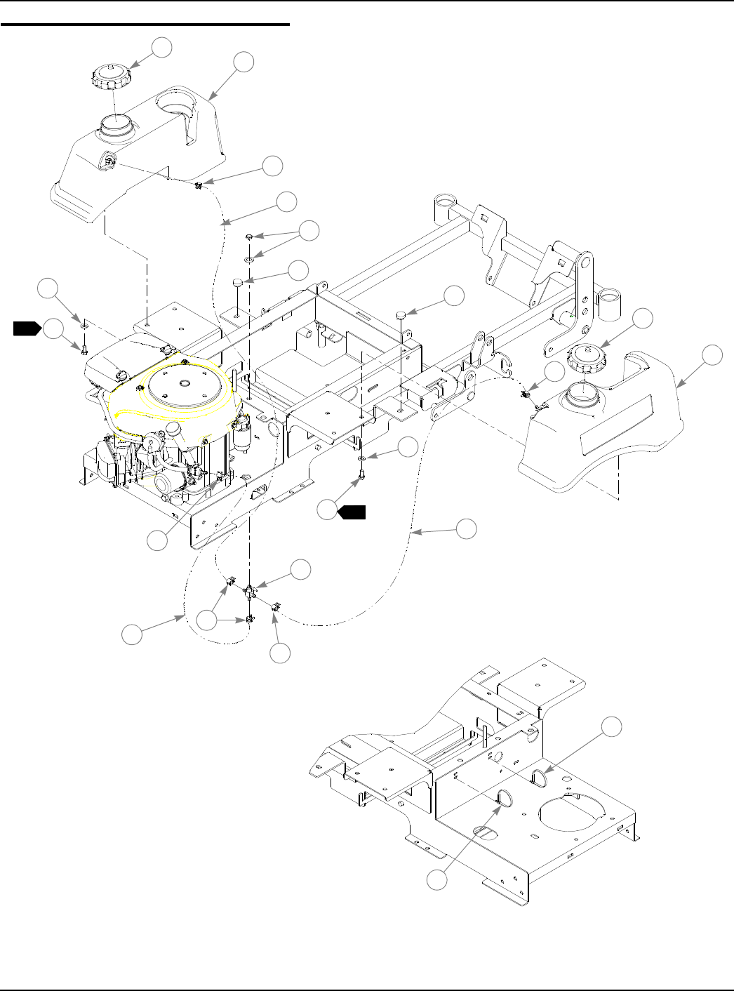
Fuel System Installation
1
11
2
3
4
4
4
4
4
5
5
6
6
7
7
8
1
9
10
11
12
8
12

333559 09/08 4-11
Fuel System Installation
NOTES:
1. Torque to 20 ft.-lbs.
2. Service parts (not shown) for fuel system:
3. Used on mowers with serial numbers higher than 07110561.
4. Used on mowers with serial numbers prior to 07110561.
INDEX
NO. SERVICE
PART NO. MFG.
PART NO. QTY. DESCRIPTION
1 779306 779306 2 3.5" FUEL CAP
2 792978 792978 1 36/42 LEFT SIDE FUEL TANK
3 792960 792960 1 36/42 RIGHT SIDE FUEL TANK
4 000323 000323 6 CLIP
5 745059 745059 1 3-WAY FUEL VALVE
6 767954 767954 10 FW .406 X .812 X .060 SAE HD ZN
7 055822 055822 8 CS .375-16 X .75 HX G5 ZNYC
8 000331 000331 2 SMALL, SHORT WIRE TIE
9 015818 015818 1 FUEL LINE, 21.00" LONG
10 015818 015818 1 FUEL LINE, 16.25" LONG (HONDA)
015818 015818 1 FUEL LINE, 12.00" LONG
(KOHLER)
015818 015818 1 FUEL LINE, 14.00" LONG
(KOHLER)
11 015818 015818 1 FUEL LINE, 8.5" LONG
12 781880 781880 2 BUMPER, .500X 1.00X .312 X.188
799221 SUCTION HOSE ASSY
794081 FUEL FILTER SCREEN
785295 FUEL GROMMET
792986 SITE-LINE TANKS FUEL FITTING
5
6
4-12 333559 09/08
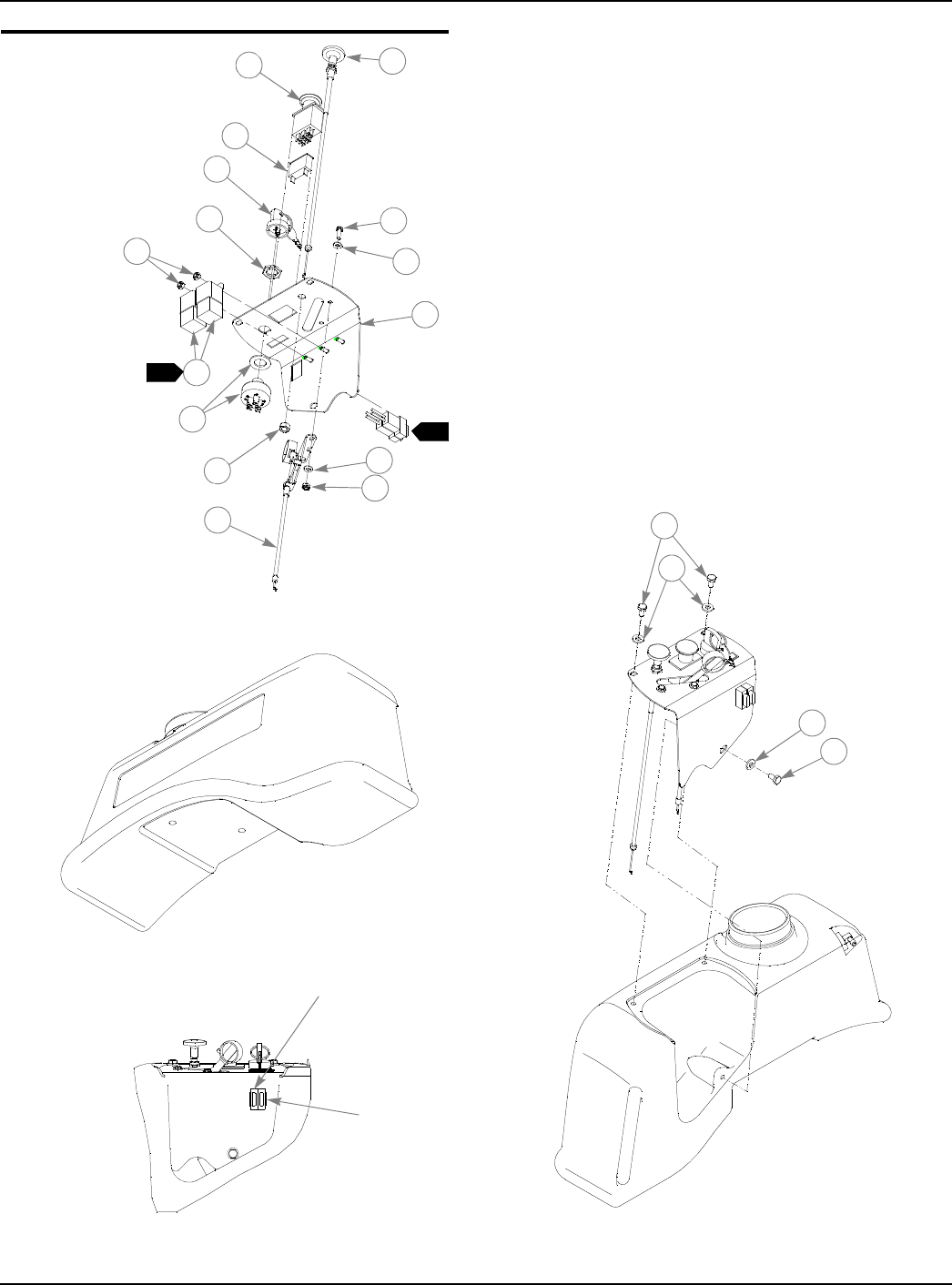
Instrument Panel Installation
1
2
3
4
5
8
6
7
5
17
8
9
11
10
12
13
12
13
FUSE SIZE
AND LOCATION
20a
10a
1
1

333559 09/08 4-13
Instrument Panel Installation
NOTES
1. Part of 601127, 793117 or 793083 (Tractor Wire Harness).
2. Includes one (1) key and one (1) 083022 metal key.
INDEX
NO. SERVICE
PART NO. MFG.
PART NO. QTY. DESCRIPTION
1 786657 786657 1 CHOKE CABLE (KOHLER)
785030 785030 1 CHOKE CABLE (HONDA)
2 776476 776476 1 PTO SWITCH
3 712257 712257 1 RED INDICATOR LIGHT
4 785808 785808 1 KEY ASSEMBLY
5 045898 045898 1 KEY SWITCH
6 714998 714998 2 MS #10-24 X .625 HX ZN
7 704932 704932 4 FW .219 X .500 X .048 ZNYC
8 059832 059832 4 NT #10-24 HX NL ZN
9 321059 321059 1 INSTRUMENT PANEL
10 026237 N/A 2 RELAY
11 793810 793810 1 THROTTLE CABLE (HONDA)
778365 778365 1 THROTTLE CABLE (KOHLER)
12 055947 055947 3 CS .250-20X .500 HX G5 ZNYC
13 768515 768515 3 FW .281 X .625 X .051/.080 HD ZNYC
2
4-14 333559 09/08
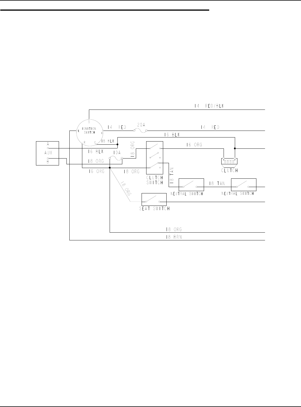
Honda 16HP Electrical Schematic (793083)

333559 09/08 4-15
Honda 16HP Electrical Schematic (793083)
4-16 333559 09/08
Kohler 15 & 17 HP Electrical Schematic (601127& 793117)
333559 09/08 4-17
Kohler 15 & 17 HP Electrical Schematic (601127&793117)

4-18 333559 09/08
This page intentionally left blank.

333559 08/08 5-1
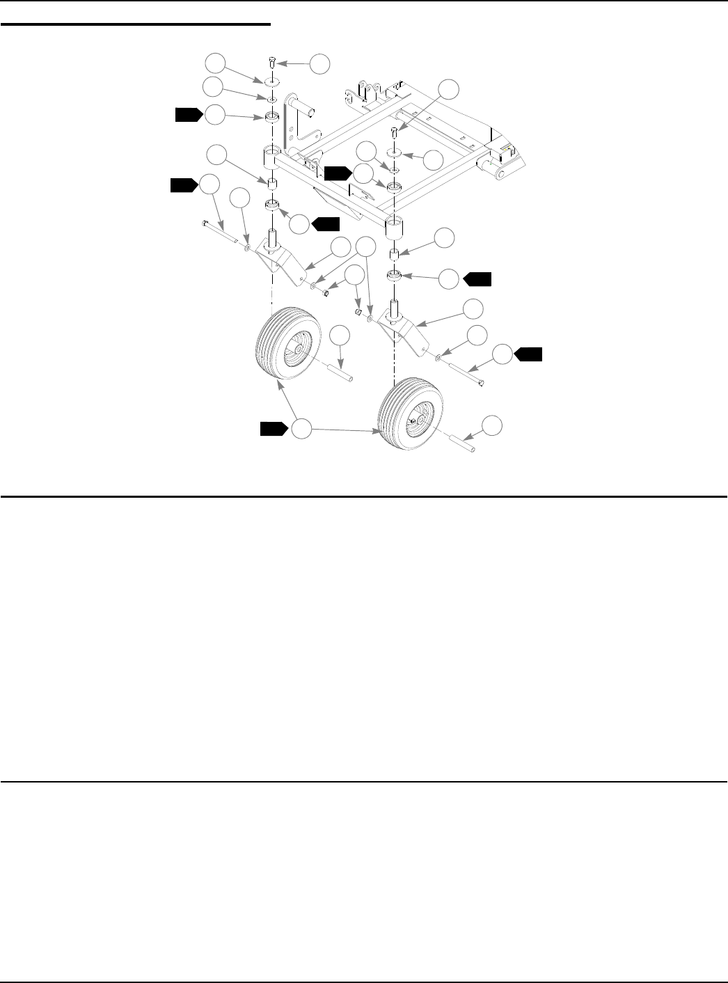
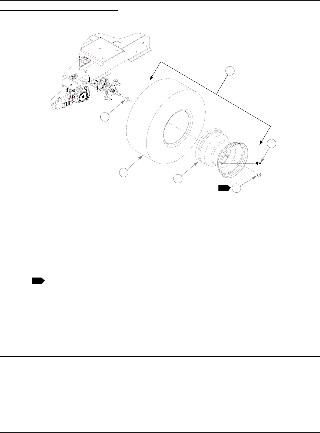
Chapter 5 Contents
Front Wheel Assembly. . . . . . . . . . . . . . . . . . . . . . . . . . . . . . . . . . . . 5-2
Front Wheel Breakdown -768044 . . . . . . . . . . . . . . . . . . . . . . . . . . . 5-3
Drive Wheel Assembly. . . . . . . . . . . . . . . . . . . . . . . . . . . . . . . . . . . . 5-4
5-2 333559
Front Wheel Assembly
NOTES:
1. Apply grease to zerks, see owners manual.
2. Torque to 75 ft.-lbs.
3. Assemble with extended inner race down.
INDEX
NO. SERVICE
PART NO. MFG. PART
NO. QTY. DESCRIPTION
1 705954 705954 2 CS .500-13 X 1.25 HX G5 ZNYC
2 344267 344267 2 FW .510 X 2.15 X .187 SPL ZNYC
3 712976 712976 2 FW .531 X 1.375 X .125 ZNYC
4 784223 784223 4 BEARING
5 784603 784603 2 SPACER
6 339689 339689 2 CASTER FORK
7 781567 781567 2 NT .50-13 HX LK NY ZNYC
8 767962 767962 4 FW .531 X 1.063 X .090 SAE HD ZN
9 042630 042630 2 CS .500-13 X 6.50 HX G5 ZNYC
10 306969 306969 2 GAGE WHEEL SPACER
11 768044 768044 2 TIRE/WHL 11X4-5 RIBBED
1
1
1
2
2
3
4
4
5
6
7
8
8
10
10
9
98
6
4
5
3
4
11
2
3
3
3
3
2
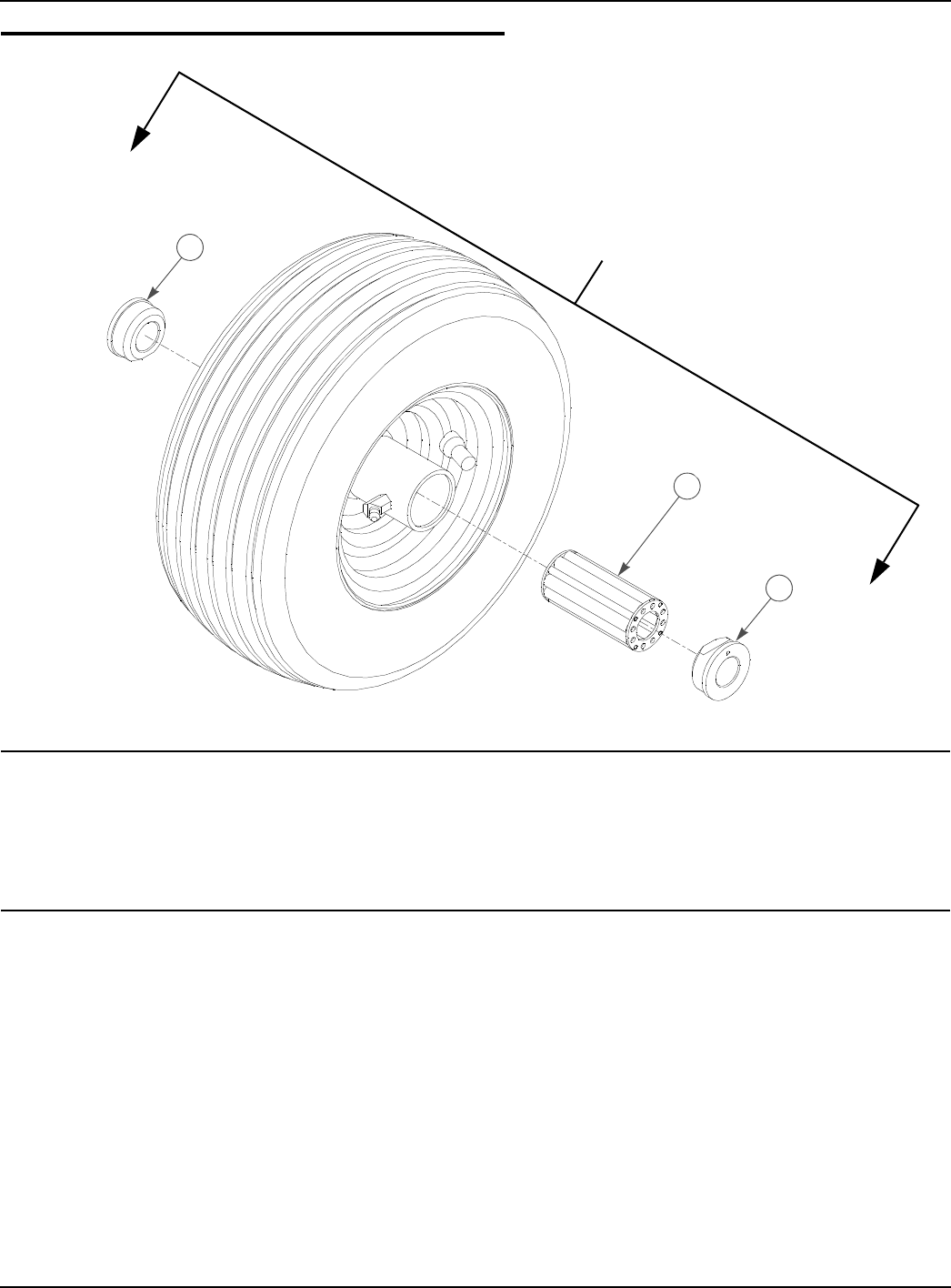
333559 08/08 5-3
Front Wheel Breakdown -768044
NOTES:
1. Inflate tire to 8-12 psi.
INDEX
NO. SERVICE
PART NO. MFG.
PART NO. QTY DESCRIPTION
1 772814 N/A 1 3/4" ROLLER BEARING
2 772806 N/A 2 BEARING CAP
768044
1
2
2
5-4 333559
Drive Wheel Assembly
NOTES:
1. Inflate tire to 8-12 psi.
2. Torque to 65-75 ft.-lb.
3. Used on 36" mowers only (927343(CE) & 927376(CE))
INDEX
NO. SERVICE
PART NO. MFG.
PART NO. QTY DESCRIPTION
1 783134 783134 2 WHEEL/TIRE ASSEMBLY 18 X 8.50 (PER 36" MOWER)
2 783142 N/A 1 TIRE 18 X 8.5-8
3 783159 N/A 1 WHEEL ASSY 8.00 X 7.00
4 019521 N/A 1 TIRE VALVE
5 061077 061077 8 WHEEL NUT (PER MOWER)
6 793406 793406 8 SPACER, .375TH X .53 ID X 1.0 0D ZN (PER MOWER)
1 784264 784264 2 WHEEL/TIRE ASSY 18 X 9.50 (PER 42” MOWER)
2 784272 N/A 1 TIRE 18 X 9.5-8
3 784280 N/A 1 WHEEL ASSY 8.00 X 6.32
4 019521 N/A 1 TIRE VALVE
5 061077 061077 8 WHEEL NUT (PER MOWER)
2
1
23
4
5
6
3

333559 08/08 6-1
Chapter 6 Contents
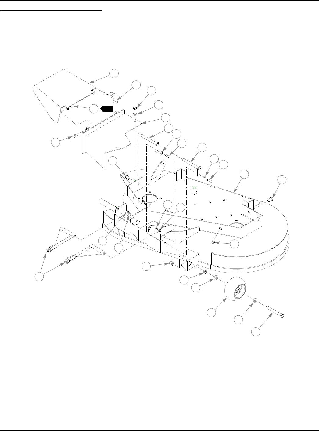
Deck Assembly 36" . . . . . . . . . . . . . . . . . . . . . . . . . . . . . . . . . . . . . . 6-2
Deck Pulley Assembly 36". . . . . . . . . . . . . . . . . . . . . . . . . . . . . . . . . 6-4
Deck Assembly 42" . . . . . . . . . . . . . . . . . . . . . . . . . . . . . . . . . . . . . . 6-8
Deck Pulley Assembly 42". . . . . . . . . . . . . . . . . . . . . . . . . . . . . . . . 6-10
Blade Spindle Assembly Breakdown. . . . . . . . . . . . . . . . . . . . . . . . 6-14
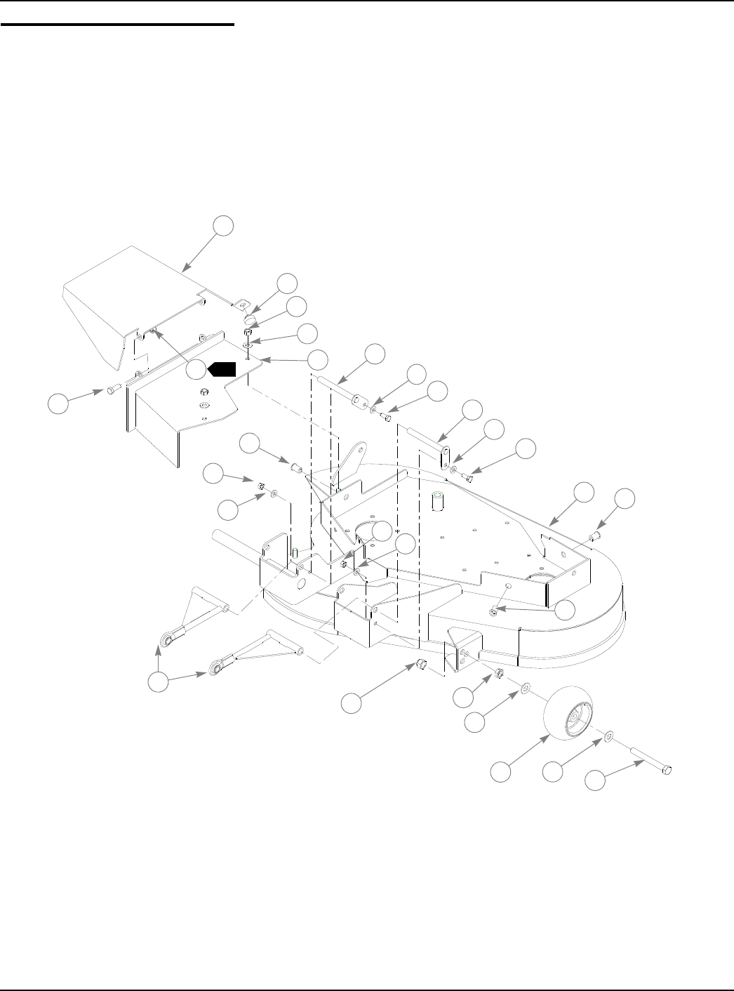
6-2 333559 09/08
Deck Assembly 36"
2
1
2
3
5
6
78
8
9
9
9
9
10
10
11 12
12
12
13
13
14
15 16
17
17
18 19
4

333559 08/08 6-3
Deck Assembly 36"
NOTES:
1. Includes items 16 through 19.
2. Do not torque, Item 1 (330399 Discharge Chute) must pivot freely.
INDEX
NO. SERVICE
PART NO. MFG. PART
NO. QTY. DESCRIPTION
1 330399 330399 1 DISCHARGE CHUTE
2 086660 086660 2 NT .375-16 HX LK NY
3 036244 036244 2 CS .375-16 X 1.00 HX G5 ZNYC
4 781880 781880 1 BUMPER, .500X 1.00X .312 X.188
5 054502 054502 2 NT .375-16 HX GRD 5 ZNYC
6 767954 767954 2 FW .406 X .812 X .060 SAE HD ZN
7 352500 352500 1 DISCHARGE CHUTE BASE
8 322974 322974 2 PULLBAR PIN
9 768523 768523 4 FW .343 X .687 X .051/.080 HD ZNYC
10 034280 034280 2 CS .312-18 X .75 HX G5 ZNYC
11 546937 315572 1 36" FASTRAK DECK
12 808485 808485 3 5/16-18 THREAD RIVET NUT
13 034272 034272 2 NT .312-18 HX G5 ZNYC
14 330225 330225 2 PULLBAR
15 781567 781567 1 NT .50-13 HX LK NY
16 053199 N/A 1 NT .500-13 HX JAM ZNYC
17 767962 N/A 2 FW .531 X 1.063 X .090 SAE HD ZN
18 031997 N/A 1 ANTI-SCALP WHEEL
19 781708 N/A 1 CS .500-13 X 4.25 HX G5 ZNYC
788166 788166 1 ANTI SCALP WHEEL ASSY
1
6-4 333559 09/08
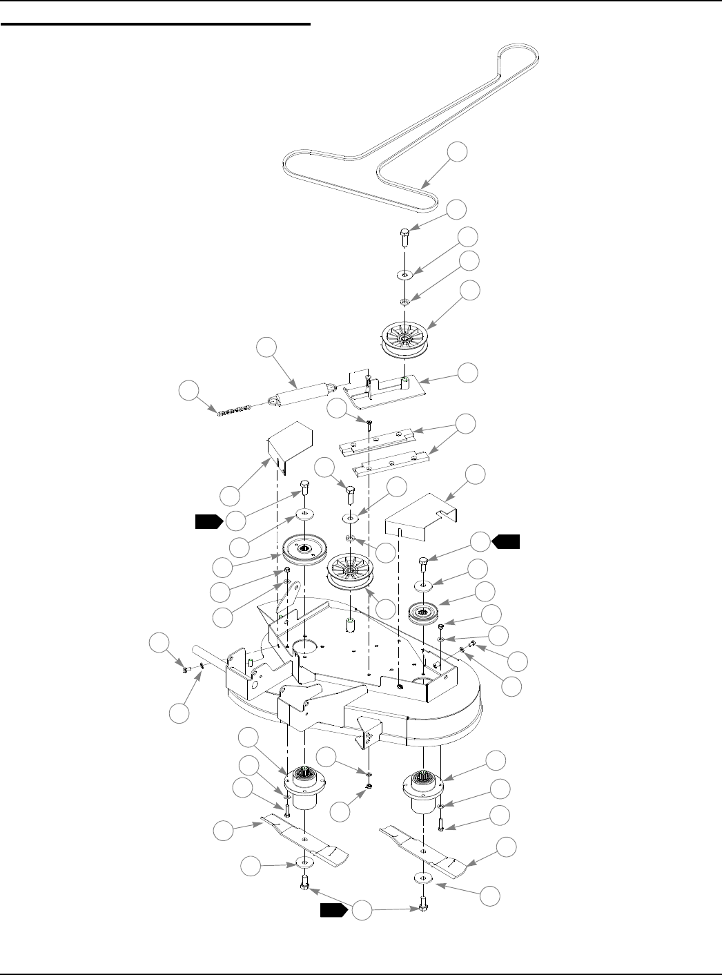
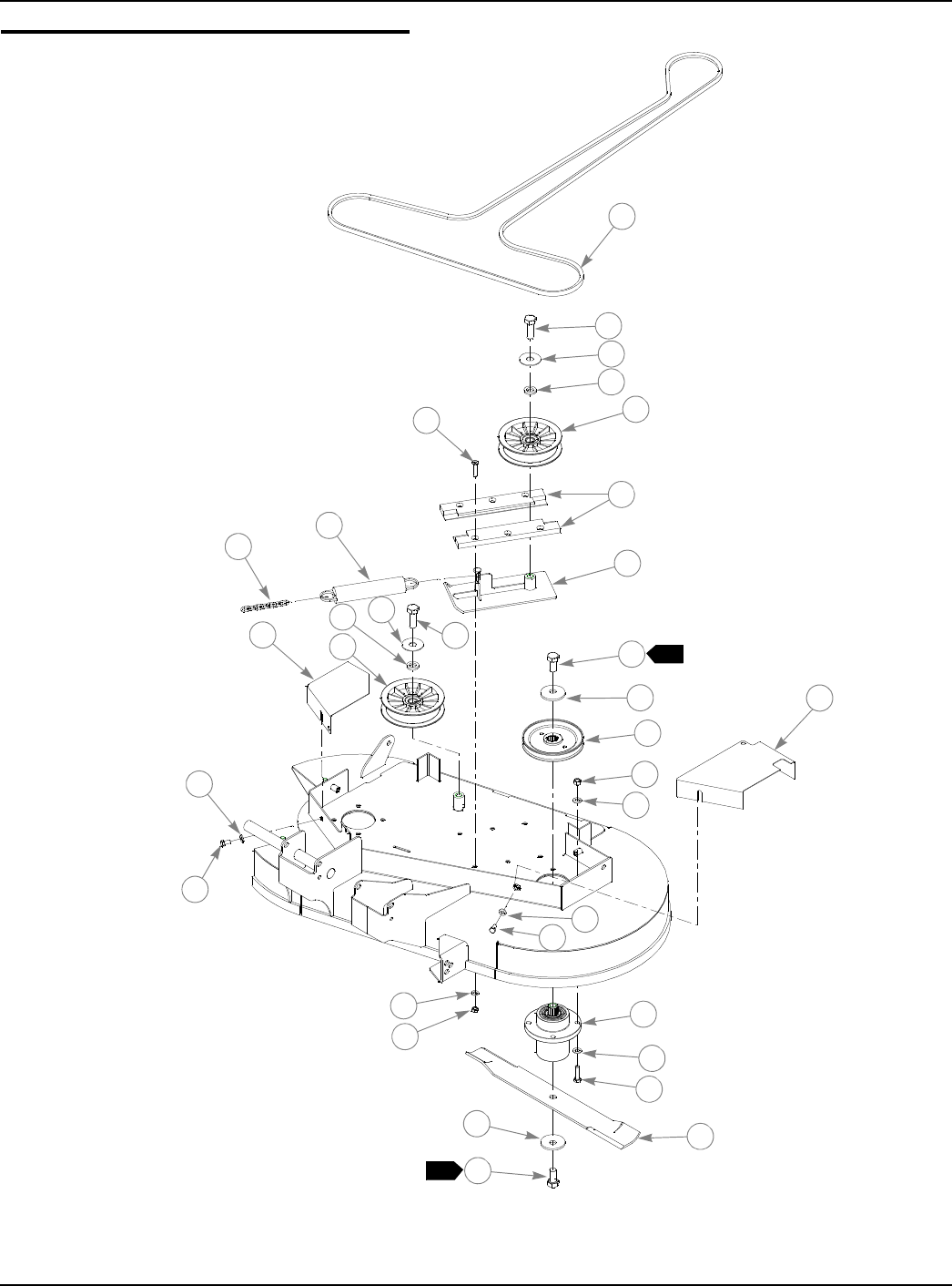
Deck Pulley Assembly 36"
1
2
2
4
4
5
5
6
8
10
9
11
12
113
13
14
14
14
14
16
15
17
17
18
18
18
18
19
20
19
20
20
21
22
22
23
23
25
24
1
13
1
3
3
7

333559 08/08 6-5
Deck Pulley Assembly 36"
NOTES:
1. Torque to 118 ft. lbs.
2. See “Belt Routing and Tensioning” on page 7-3 for belt tensioning
3. Deck belt tensioning idler for mowers with serial numbers prior to
06010082 (see FIG 6-1).
INDEX
NO. SERVICE
PART NO. MFG. PART
NO. QTY. DESCRIPTION
1 793828 793828 1 A-SECTION BELT (FASTRAK 36")
2 025007 025007 2 CS .625-11 X 1.75 HX G5 ZNYC
3 046821 046821 2 FW .656 X 2.00 X .078 ZNYC
4 797449 797449 2 FW .650 X 1.00 X .180 ZNYC G5
5 784504 784504 2 IDLER PULLEY, 5.00"OD, 5/8"ID
6 784199 784199 6 CS .312-18 X 1.25 FLT SH
7 601434 601434 2 UHMW IDLER SLIDE
8 321877 321877 1 DECK IDLER
9 364315 059931 1 SPRING CHAIN
10 781302 781302 1 IDLER SPRING
11 321398 321398 1 RIGHT PULLEY COVER
12 330324 330324 1 LEFT PULLEY COVER
13 781872 781872 4 CS .625-11 X 1.25 HX G5 ZNYC
14 782474 782474 4 CW .631 2.250 X .187 PNT
15 793786 793786 1 DECK PULLEY (FASTRAK 36")
16 793778 793778 1 DECK PULLEY (FASTRAK 36"/42")
17 054502 054502 8 NT .375-16 HX GRD 5 ZNYC
18 767954 767954 16 FW .406 X .812 X .060 SAE HD ZN
19 064006 064006 4 CS .312-18 X .625 HX G5 ZNYC
20 768523 768523 10 FW .343 X .687 X .051/.080 HD ZNYC
21 058776 058776 6 NT .312-18 HX NL ZNYC
22 783506 783506 2 BLADE SPINDLE ASSEMBLY
23 005116 005116 8 CS .375-16 X 1.375 HX G5 ZNYC
24 793794 793794 1 20.50" 42D X 0.631 CW BLADE
25 793802 793802 1 13.75" 42D X 0.631 CW BLADE
28 079186 N/A 6 CS .312-18 X 1.25 HX G5
29 712927 N/A 6 FW .344 X 1.00 X .12 HRD ZN
30 785832 N/A 2 DECK IDLER UHMW CLAMP
31 787069 N/A 2 DECK IDLER UHMW RISER
32 017129 N/A 6 FW .440 X 1.000 X .083 ZNYC
3
3
3
3
3
6-6 333559 09/08
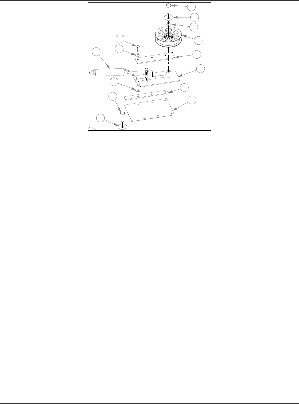
FIG. 6-1 2
3
4
5
30
9
31
12
28
29
11
32
13
15

333559 08/08 6-7
This page intentionally left blank.
6-8 333559 09/08
Deck Assembly 42"
1
2
2
3
5
6
7
89
9
9
9
10
10
11 12
12
12
13
13
14
15
16
17
18
19
8
4
17

333559 08/08 6-9
Deck Assembly 42"
NOTES:
1. Includes items 16 through 19.
2. Do not torque, Item 1 (330399 Discharge Chute) must pivot freely.
INDEX
NO. SERVICE
PART NO. MFG. PART
NO. QTY. DESCRIPTION
1 330399 330399 1 DISCHARGE CHUTE
2 086660 086660 2 NT .375-16 HX LK NY
3 036244 036244 2 CS .375-16 X 1.00 HX G5 ZNYC
4 781880 781880 1 BUMPER, .500X 1.00X .312 X.188
5 054502 054502 2 NT .375-16 HX GRD 5 ZNYC
6 767954 767954 2 FW .406 X .812 X .060 SAE HD ZN
7 352500 352500 1 DISCHARGE CHUTE BASE
8 322974 322974 2 PULLBAR PIN
9 768523 768523 4 FW .343 X .687 X .051/.080 HD ZNYC
10 034280 034280 2 CS .312-18 X .75 HX G5 ZNYC
11 546929 316919 1 42" FASTRAK DECK
12 808485 808485 3 5/16-18 THREAD RIVET NUT
13 034272 034272 2 NT .312-18 HX G5 ZNYC
14 330225 330225 2 PULLBAR
15 781567 781567 1 NT .50-13 HX LK NY
16 053199 N/A 1 NT .500-13 HX JAM ZNYC
17 767962 N/A 2 FW .531 X 1.063 X .090 SAE HD ZN
18 031997 N/A 1 ANTI-SCALP WHEEL
19 781708 N/A 1 CS .500-13 X 4.25 HX G5 ZNYC
788166 788166 1 ANTI SCALP WHEEL ASSY
1
6-10 333559 09/08
Deck Pulley Assembly 42"
1
2
1
3
3
5
2
5
6
8
10
9
11
12
13
14
15
16
17
19
19
19
18
20
18
21
17
22
23
14
24
1
4
4
7

333559 08/08 6-11
Deck Pulley Assembly 42"
NOTES:
1. Torque to 118 ft. lbs.
2. See “Belt Routing and Tensioning” on page 7-3 for belt tensioning
3. Deck belt tensioning idler for mowers with serial numbers prior to
06010082 (see FIG 6-2).
4. Item 7 (601434) replaces idler slide components 600171, 600189 and
786335 found on mowers with serial numbers prior to 08010000.
INDEX
NO.
SERVICE
PART NO.
MFG. PART
NO. QTY. DESCRIPTION
1 793893 793893 1 A-SECTION BELT (FASTRAK 42")
2 025007 025007 2 CS .625-11 X 1.75 HX G5 ZNYC
3 046821 046821 2 FW .656 X 2.00 X .078 ZNYC
4 797449 797449 2 FW .650 X 1.00 X .180 ZNYC G5
5 784504 784504 2 IDLER PULLEY, 5.00"OD, 5/8"ID
6 784199 784199 6 CS .312-18 X 1.25 FLT SH ZY
7 601434 601434 2 UHMW IDLER SLIDE
8 321877 321877 1 DECK IDLER
9 259812 059931 1 SPRING CHAIN
10 781302 781302 1 IDLER SPRING
11 321398 321398 1 RIGHT PULLEY COVER
12 321042 321042 1 LEFT PULLEY COVER
13 781872 781872 2 CS .625-11 X 1.25 HX G5 ZNYC
14 782474 782474 4 CW .631 2.250 X .187 PNT
15 793778 793778 2 DECK PULLEY (FASTRAK 36"/42")
16 054502 054502 8 NT .375-16 HX GRD 5 ZNYC
17 767954 767954 16 FW .406 X .812 X .060 SAE HD ZN
18 064006 064006 4 CS .312-18 X .625 HX G5 ZNYC
19 768523 768523 10 FW .343 X .687 X .051/.080 HD ZNYC
20 058776 058776 6 NT .312-18 HX NL ZNYC
21 783506 783506 2 BLADE SPINDLE ASSEMBLY
22 005116 005116 8 CS .375-16 X 1.375 HX G5 ZNYC
23 793794 793794 2 20.50" 42D X 0.631 CW BLADE
24 781872 781872 2 CS .625-11 X 1.25 HX G5 ZNYC
27 712927 N/A 6 FW .344 X 1.00 X .12 HRD ZN
28 785832 N/A 2 DECK IDLER UHMW CLAMP
29 787069 N/A 2 DECK IDLER UHMW RISER
30 017129 N/A 6 FW .440 X 1.000 X .083 ZNYC
31
6-12 333559 09/08
FIG. 6-2 2
3
4
5
29
9
12
27
28
11
31
3
15
30

333559 08/08 6-13
This page intentionally left blank.
6-14 333559 09/08
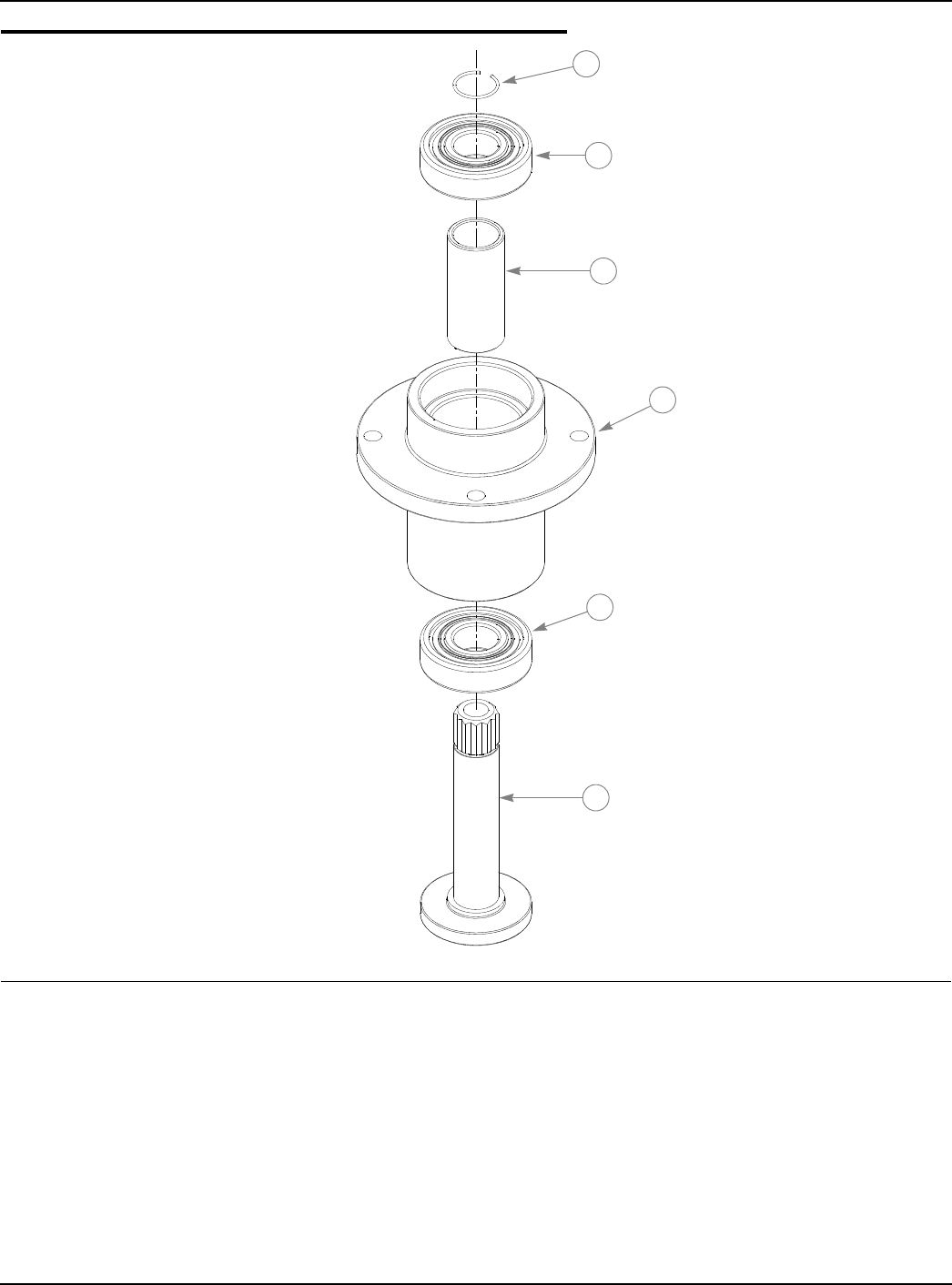
Blade Spindle Assembly Breakdown
c
INDEX
NO. SERVICE
PART NO. MFG. PART
NO. QTY. DESCRIPTION
1 783548 N/A 1 BLADE SPINDLE RETAINING RING
2 783555 N/A 2 BLADE SPINDLE BEARING
3 783530 N/A 1 BLADE SPINDLE SPACER
4 783514 N/A 1 BLADE SPINDLE HOUSING
5 783522 N/A 1 BLADE SPINDLE SHAFT
1
2
2
3
4
5

333559 08/08 6-15
NOTES:

6-16 333559 09/08
This page intentionally left blank.

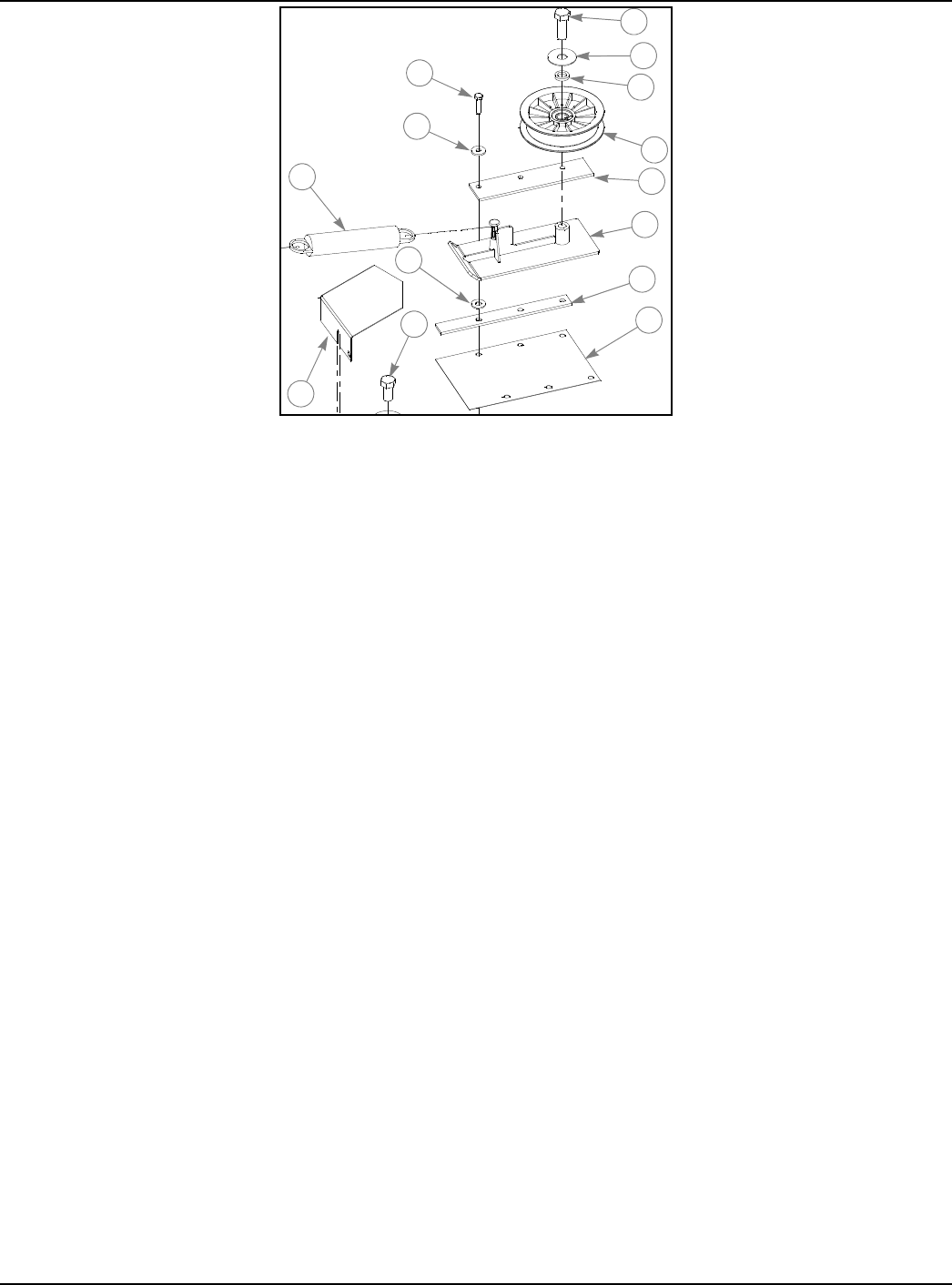
333559 08/08 7-1
Chapter 7 Contents
Deck Installation . . . . . . . . . . . . . . . . . . . . . . . . . . . . . . . . . . . . . . . . 7-2
Belt Routing and Tensioning . . . . . . . . . . . . . . . . . . . . . . . . . . . . . . . 7-3
Seat Installation . . . . . . . . . . . . . . . . . . . . . . . . . . . . . . . . . . . . . . . . . 7-4
7-2 333559
Deck Installation
NOTES:
INDEX
NO. SERVICE
PART NO. MFG. PART
NO. QTY. DESCRIPTION
1 781567 781567 2 NT .500-13 HX GR 8 ZY NL
2 767962 767962 4 FW .531 X 1.063 X .090 SAE HD ZN
3 017616 017616 2 CS .500-13 X 1.75 HX G5 ZNYC
4 704643 704643 5 NT .437-14 HX FLG ZN
5 055749 055749 3 CS .437-14 X 1.75 HX G5 ZNYC
1
2
34
4
4
5
5
5
2
333559 08/08 7-3
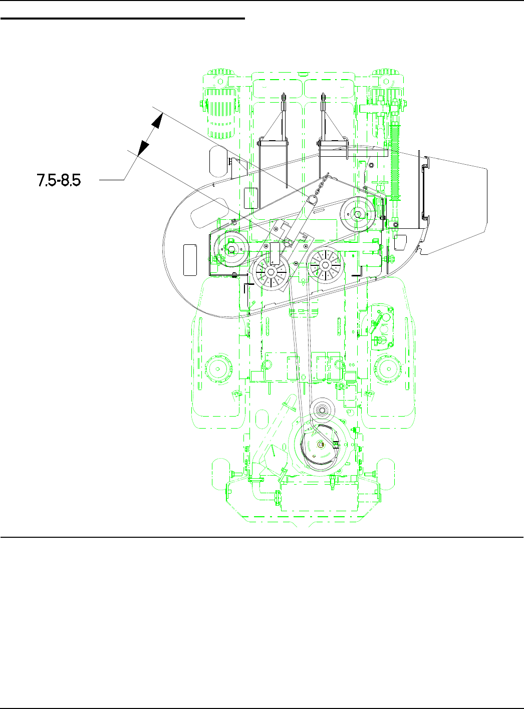
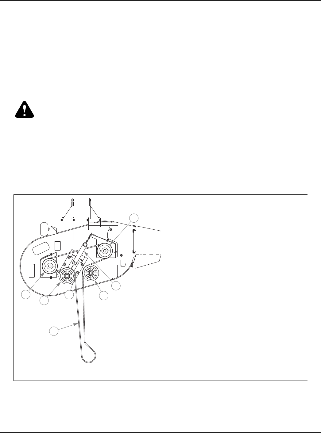
Belt Routing and Tensioning
NOTES:
1. Spring length after tensioning belt–measured from outside of hook to outside
of hook.
2. Route belt as shown.
7-4 333559
Seat Installation
NOTES:
1. Do not torque, Item 4 (320275 Seat Pan) must pivot on these fasteners.
2. Available service parts and options for Michigan Seat:
INDEX
NO. SERVICE
PART NO. MFG. PART
NO. QTY. DESCRIPTION
1 793679 793679 1 STANDARD MICHIGAN SEAT
2 086660 086660 3 NT .375-16 HX LK NY
3 767954 767954 3 FW .406 X .812 X .060 SAE HD ZN
4 320275 320275 1 SEAT PAN
5 052860 052860 2 CS .375-16 X 1.25 HX G5 ZNYC
6 793851 793851 2 COMPRESSION SPRING, 1.25X4.00X.188
7 768523 768523 4 FW .343 X .687 X .051/.080 HD ZNYC
8 034280 034280 4 CS .312-18 X .750 HX G5 ZNYC
9 036244 036244 2 CS .375-16 X 1.00 HX G5 ZNYC
797456 ARMREST KIT (ROUND STYLE)
793315 SEAT SWITCH KIT
1
3
2
3
5
6
4
7
8
9
1
2

333559 08/08 8-1
Chapter 8 Contents
Tractor Decals . . . . . . . . . . . . . . . . . . . . . . . . . . . . . . . . . . . . . . . . . . 8-2
42" Deck Decals . . . . . . . . . . . . . . . . . . . . . . . . . . . . . . . . . . . . . . . . 8-4
36" Deck Decals . . . . . . . . . . . . . . . . . . . . . . . . . . . . . . . . . . . . . . . . 8-5
8-2 333559
Tractor Decals
2
4
5
3
6
7
9
8
12
10
13
15
14
11
1
16
17

333559 08/08 8-3
Tractor Decals
NOTES:
INDEX
NO. SERVICE
PART NO. MFG. PART
NO. QTY. DESCRIPTION
1 794545 794545 1 DEFLECTOR SHIELD DECAL
2 N/A 083279 1 TURF PROD SERIAL NO PLATE
3 784710 784710 1 FASTRAK DECAL
4 782573 782573 1 FIRST ZERO TURN DECAL
5 793547 793547 1 FASTRAK OPERATION DECAL
6 793588 793588 1 HUSTLER NAME PLATE
7 794305 794305 1 DECK HEIGHT DECAL
8 785139 785139 1 FASTRAK LEFT SIDE STEERING DECAL
9 785220 785220 1 FASTRAK RIGHT SIDE STEERING DECAL
10 793703 793703 1 INSTRUMENT PANEL DECAL
11 793554 793554 1 FASTRAK 36/42 FUEL VALVE DECAL
12 771436 771436 1 STABILIZER DECAL
13 727016 727016 1 BATTERY DECAL
14 788968 788968 1 ENGINE COMPARTMENT DECAL
15 785147 785147 1 SERVICE DECAL
16 600899 600899 1 PUMP BELT WARNING DECAL
17 600941 600941 1 PATENT DECAL
8-4 333559
42" Deck Decals
x
NOTES:
INDEX
NO. SERVICE
PART NO. MFG. PART
NO. QTY. DESCRIPTION
1 793521 793521 1 42" DECK ID DECAL
2 793687 793687 1 BELT ROUTING DECAL
3 794503 794503 1 STEP TREAD
4 793570 793570 1 DECK WARNING DECAL
5 727172 727172 1 “MADE IN U.S.A.” DECAL
6 794297 794297 1 DISCHARGE CHUTE DECAL
1
2
3
4
6
5
333559 08/08 8-5
36" Deck Decals
x
NOTES:
INDEX
NO. SERVICE
PART NO. MFG. PART
NO. QTY. DESCRIPTION
1 793513 793513 1 36" DECK ID DECAL
2 793687 793687 1 BELT ROUTING DECAL
3 794503 794503 1 STEP TREAD
4 727172 727172 1 “MADE IN U.S.A.” DECAL
5 793570 793570 1 DECK WARNING DECAL
6 794297 794297 1 DISCHARGE CHUTE DECAL
2
1
4
5
6
3

8-6 333559

333559 09/08 9-1
Chapter 9 Contents
Maintenance & Adjustment Safety. . . . . . . . . . . . . . . . . . . . . . . . . . . 9-2
Maintenance . . . . . . . . . . . . . . . . . . . . . . . . . . . . . . . . . . . . . . . . . . . 9-7
Adjustments. . . . . . . . . . . . . . . . . . . . . . . . . . . . . . . . . . . . . . . . . . . 9-20

9-2 333559 09/08
Maintenance & Adjustment Safety
This safety alert symbol is used to call attention to a message intended to provide a reasonable degree of
PERSONAL SAFETY for operators and other persons during the normal operation and servicing of this equip-
ment.
DANGER – denotes immediate hazards which WILL result in severe personal injury or death.
WARNING - denotes a hazard or unsafe practice which COULD result in severe personal injury or death.
This manual uses two other words to highlight information. IMPORTANT calls attention to special mechan-
ical information and NOTE: emphasizes general information worthy of special attention.
All operators and mechanics should read this manual, and be instructed about safe operating and mainte-
nance procedures. If the operators or mechanics cannot read and understand English, it is the owner’s
responsibility to explain this material to them.
Improper use or maintenance by the operator, mechanic, or owner can result in injury. To reduce the potential for injury,
comply with these safety instructions and always pay attention to the safety alert symbol, which means DANGER or
WARNING - “personal safety instructions.” Failure to comply with the instructions may result in personal injury or death.
Incorrect usage of this machine may result in severe injury. Personnel operating and maintaining it should be trained in
the proper use and should read the manuals completely and thoroughly before attempting to set-up, operate, adjust, or
service this machine.
The Quick Reference Decals are designed to give the operator brief information needed in the daily opera-
tion and service of the machine. These decals are not intended to be used in place of this manual but instead
is to be used as an extension of this manual. These decals should not be removed or obliterated. Replace
these decals if they become unreadable.
It is the owner’s responsibility to make certain that the operators and mechanics read and understand this
manual and all decals before operating this machine. It is also the owner’s responsibility to make certain that
the operators and mechanics area qualified and physically able individuals, properly trained in the operation
of this equipment. All operators and mechanics must become familiar with the safe operation of the equip-
ment, operator controls and safety signs before operating the equipment.
Never let children or untrained people operate or service the equipment. Local regulation may restrict the
age of the operator.
The owner should also ensure that the operators and mechanics know that they are responsible for their
own safety as well as the safety of other persons within the vicinity. Remember, the operator is responsible for
accidents or hazards occurring to other people or their property.
Safe Maintenance & Adjustment Practices
This product is capable of amputating hands and feet and throwing objects. Always follow all safety
instructions to avoid serious injury or death.
Unless specifically required, DO NOT have engine running when servicing or making adjustments to tractor. Park
the machine on level ground. Place control levers in the park brake position, disengage deck clutch, lower deck,
remove ignition switch key and disconnect the negative battery cable before doing any maintenance. Wait for all
movement to stop before adjusting, cleaning or repairing. Repairs or maintenance requiring engine power should
be performed by trained personnel only. To prevent carbon monoxide poisoning, be sure proper ventilation is
available when engine must be operated in an enclosed area. Read and observe safety warnings in front of
manual.
Follow daily and weekly checklists, making sure hoses are tightly secured and bolts are tightened.
Keep your machine clean and remove any deposits of trash and clippings, which can cause engine fires and
hydraulic overheating as well as excessive belt wear. Clean up oil or spillage. Allow machine to cool before
storing.
Clean flammable material from machine. Prevent fires by keeping the top of the deck, engine
compartment, exhaust area, battery, hydraulic lines, fuel line, fuel tank and operator’s station clean of
accumulated trash, grass clippings, and other debris. Always clean up spilled fuel and oil.

333559 09/08 9-3
Always wear adequate ear protection, such as earplugs, when operating this equipment as prolonged exposure to
uncomfortable or loud noises can cause impairment or loss of hearing. Do not wear radios or music headphones
while operating the machinery. Safe operation requires your full attention.
Never put hands or feet under any part of the machine while it is running.
Except when changing or checking belt, always keep belt covers on mower for safety as well as cleanliness.
Stop the engine before removing the grass catcher or unclogging the discharge chute. Never clear the discharge
chute with the engine running. Turn off the engine and be sure the blades have stopped before cleaning. Use a
stick to clear a plugged discharge area. Never use your hand!
Exercise caution when loading or unloading the machine onto a trailer or truck.
Always wear safety goggles or safety glasses with side shields when operating the mower.
Always wear adequate eye protection when servicing the battery, hydraulic system or when grinding mower blades
and removing accumulated debris.
Use extra caution when handling gasoline and other fuels. They are flammable and vapors are explosive.
Never remove fuel cap or refuel tractor while engine is running; never refuel near an open flame or near devices
which can create a spark. Refuel outdoors. Never refuel or drain the fuel from the machine indoors.
Never attempt to start engine when there is a strong odor of gasoline fumes present. Locate and correct cause.
Never run the engine in an enclosed area unless exhaust is vented to the outside. Exhaust gases contain carbon
monoxide which is odorless and deadly poison.
Never attempt to make any adjustments or repairs to the tractor drive system, mower deck or any attachment while
the tractor engine is running or deck clutch is engaged. Repairs or maintenance requiring engine power should
be performed by trained personnel only.
Never work under the machine or attachment unless it is safely supported with jack stands. Make certain machine
is secure when it is raised and placed on the jack stands. The jack stands should not allow the machine to move
when the engine is running and the drive wheels are rotating. Use only certified jack stands. Use only
appropriate jack stands, with a minimum weight rating of 2000 pounds to block the unit up. Use in pairs only.
Follow the instructions supplied with the vehicle stands.
Before working on or under the deck, make certain engine cannot be accidentally started. Shut engine off and
remove ignition switch key for maximum safety. Repairs or maintenance requiring engine power should be
performed by trained personnel only.
Use a stick or similar instrument to clean under the mower making sure that no part of the body, especially arms
and hands are under mower.
Exercise caution when working under the deck as the mower blades are extremely sharp. Wrap the blade(s) or
wear gloves and use extra caution when servicing them.
Do not touch hot parts of machine.
Keep nuts and bolts tight, especially the blade attachment bolts. Keep equipment in good working condition.
Never tamper with safety devices. Check their proper operation regularly.
Grass collection system components are subject to wear, damage and deterioration, which could expose moving
parts or allow objects to be thrown. Frequently check components and replace with manufacturer’s
recommended parts, when necessary.
Use only genuine Hustler replacement parts to ensure that original standards are maintained.
Using a ramp
Use extreme caution when loading and unloading a unit onto a truck or trailer with a ramp.
Use only a single, full width ramp; do not use individual ramps for each side of the unit. Having a full width ramp
provides a surface for the tractor frame to contact if the unit starts to tip backwards. It also reduces the risk of a
wheel going off and the machine tipping over.
Do not exceed a 15 degree angle between the ramp and the ground or between the ramp and the trailer or truck.
When on a ramp avoid sudden acceleration.

9-4 333559 09/08
Children
Tragic accidents can occur if the operator is not alert to the presence of children. Children are often
attracted to the machine and the mowing activity. Never assume that children will remain where you last saw
them.
Never leave machine unattended with ignition key in switch, especially with children present.
Children or bystanders may be injured if they move or attempt to operate the tractor while it is unattended. Always
disengage deck clutch, place steering control levers in park brake position, stop tractor engine, and remove
ignition key when leaving operator’s seat.
Keep children out of the mowing area and under the watchful care of a responsible adult other the operator.
Be alert and turn the machine off if children enter the area.
Before and while backing, look behind and down for small children.
Never carry children, even with the blades off. They may fall off and be seriously injured or interfere with safe
machine operating. Children who have been given rides in the past may suddenly appear in the mowing area for
another ride and be run over or backed over the machine.
Never allow children to operate the machine.
Use care when approaching blind corners, shrubs, trees, the end of a fence or other objects that may obscure
vision.
Never allow children of others in or on towed equipment.
333559 09/08 9-5
Safety and Instruction Decals
Specific safety warning decals are located on the equipment near the immediate areas of potential hazards. These
decals should not be removed or obliterated. Replace them if they become non-readable.
The following illustrations show the various safety decals that are located on the machine. A brief explana-
tion is shown to help the operator understand the meanings of these decals.
Read Owner’s Manual and Quick Reference Decal before attempting to operate this machine.
Avoid skin contact with battery acid. Always wear eye protection when checking the battery, acid can cause
serious injury to skin and eyes. If contact occurs, flush area with clean water and call physician immediately.
Acid will also damage clothing.
Do not allow open flame near the battery when charging.
Hydrogen gas forms inside the battery. This gas is both toxic and flammable and may cause an explosion if
exposed to flame. Always remove the negative ground first and replace it last.
Do not overfill battery. Electrolyte may overflow and damage paint, wiring or structure. When cleaning the
battery, use soap and water. Be careful not to get soap and water into the battery. Use soda mixed in water to
clean corrosion off the terminals.
Do not remove or modify stabilizer wheels or rear engine guard or
injury can result. When operating on a slope of 15° or more, be aware
of any condition that may cause the tractor drive tires to lose traction
resulting in a possible loss of control of the machine.
If you loose steering control while operating the machine, place the
steering control levers in the park brake position immediately. Inspect the machine and involve
your Hustler dealer to resolve the problem before continuing to operate.
If pump belt fails, steering control will be lost. Refer to owner’s manual for inspection and
replacement intervals and refer to above paragraph for emergency procedures.
Do not smoke while refueling.
Do not fill tank with engine running, or while the engine is hot.
Allow engine to cool before storing machine inside a building.
Store away from open flame or spark if there is fuel in tank.
Clean up any gasoline spills.
Do not refuel while in enclosed trailer or other enclosed areas.
Never operate the mower deck with side deflector damaged, altered, removed or in
raised position, except when the entire grass catcher attachment or mulching system
is being used. Stay clear of mower blades as long as engine is running.Keep a safe
distance from machine. Keep shields or covers in place while machine is in
operation. Keep hands away from rotation pulleys and belts.
Part Number
727016
Part Number
793547
Part Number
600899
Part Number
793570

9-6 333559 09/08
Whirling blades! Keep hands and feet away. Beware of thrown objects. Never operate the mower
deck with side deflector damaged, altered, removed or in raised position, except when the en-
tire grass catcher attachment or mulching system is being used. Stay clear of mower blades as
long as engine is running. Beware of thrown object.
Keep shields or covers in place while machine is in operation. Keep hands away from rotating pul-
leys and belts.
Part Number
794297
Part Number
727453
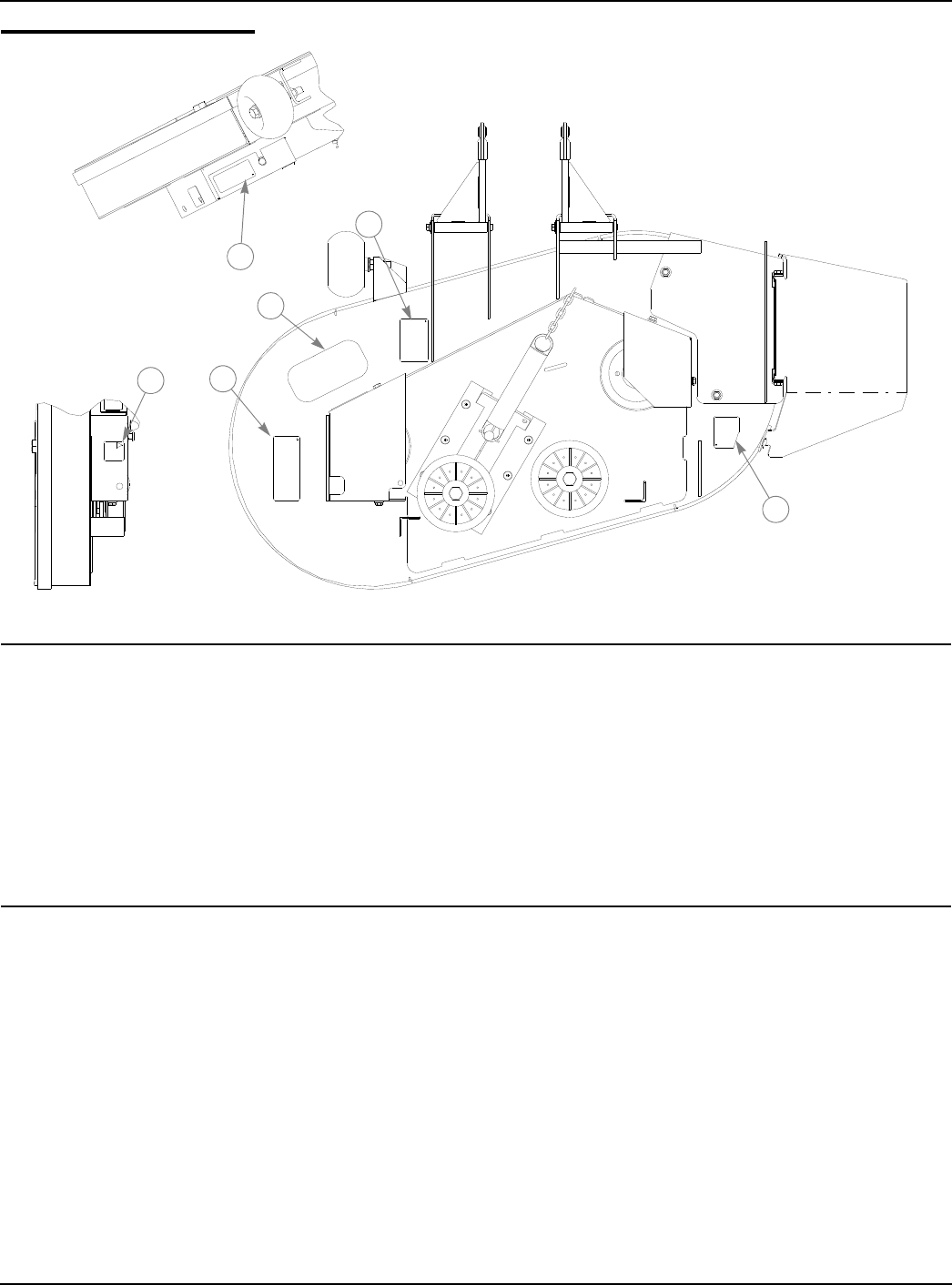
333559 09/08 9-7
Maintenance
FIG. 1
1
7
7
16
2
3a
3b
4
5
6
6
8
9
9
10
10
11
11
12
14
13
MAINTENANCE LOCATOR
CHART
Viewed from top of unit
1. Engine Oil Fill & Dipstick (Honda & Kohler)
2. Fuel Filter
3a. Engine Air Cleaner (Honda)
3b. Engine Air Cleaner (Kohler)
4. Engine Oil Drain Plug)
5. Battery
6. Fuel Tanks
7. Wheel Bearing Zerks (2)
8. Engine Oil Filter
9. Deck Lift Pivot Zerks (4)
10. Park Brake Switch (2)
11. Drive Tire
12. Deck Belt
13. Pump Belt
14. Blades
15. Engine Air Intake Screen
16. Front Tires
15

9-8 333559 09/08
NOTES:
1. Initial oil change is after 5 hours of operation. Thereafter, change oil after ever 40 hours. operating. Change
more often under dusty or dirty conditions and during hot weather periods.
2. Torque initially and after first 2 hours of operation.
3. Change engine oil filter per the engine manufacturer’s recommendations. Refer to Engine Owner’s Manual
for recommendations and other maintenance items.
4. Service more often under dusty or dirty conditions.
5. Pump drive belt only–Inspect every 6 months or 100 hours and replace of worn or cracking is noticed.
Otherwise, replace ever 200 hours or 2 years, whichever comes first.
6. Check fuel line hoses, fuel valve and grommet for any cracks or leaks
7. Honda engine only.
8. Kohler engine only.
References:
a Refer to Engine Owner’s Manual
NOTE: After completing Maintenance cycle (100 hours), repeat cycle.
Introduction
Regular maintenance is the best prevention for costly downtime or expensive, premature repair. The fol-
SERVICE AT INTERVALS INDICATED WEEKLY OR 50
HOURS ANNUALLY OF
100 HOURS
Verify safety start interlock system Prior to each use
Visually inspect unit for loose hardware and/or damaged
parts
Prior to each use
Visually inspect tires Prior to each use
Check oil level, engine (1) Prior to each use or ever 4 hrs.
Clean air intake screen (4) Prior to each use or ever 4 hrs.
Clean Foam element (4) Prior to each use or ever 4 hrs.
Check fuel level Prior to each use
Blades–sharpen & securely fastened Prior to each use
Discharge chute–securely in place & in lowest position Prior to each use
Grease deck height pivots X
Grease front wheel bearings X
Change engine oil & filter (1) (3) X
Clean cylinder and head fins (a) X
Check battery connections X
Check tire pressure with a gauge X
Clean engine exterior (a) X
Replace air cleaner paper element (4) X
Clean and re-gap spark plugs (a) X
Check pump and deck belt tension & condition (5) X
Check fuel lines (6) X
Tighten lug nuts on wheels (2) X
Change fuel filter X
Replace spark plugs X
Check engine valve clearance (a) Every 200 hours or 2 years
Service starter (8)(a) Every 200 hours or 2 years
Replace EZT pump belt Every 200 hours or 2 years

333559 09/08 9-9
lowing pages contain suggested maintenance information and schedules which the operator should follow on
a routine basis.
Remain alert for unusual noises, they could be signaling a problem. visually inspect the machine for any
abnormal wear or damage. A good time to detect potential problems is while performing scheduled mainte-
nance service. Correcting the problem as quickly as possible is the best insurance.
Clear away heavy build-up of grease, oil and dirt, especially in the engine and under the seat platform
areas; minute dust particles are abrasive to close-tolerance engine and hydraulic assemblies.
Daily inspect mower for grass clippings and wire and string tangles. The underside of the mower deck will
collect a build-up of grass clippings and dirt, especially when grass is wet or has high moisture content. This
build-up will harden, restricting blade and air movement and will probably show a poorer quality of cutting.
Therefore, it should be removed routinely.
To do this, it will be necessary to raise and block the deck, using jack stands or blocks, in the full up posi-
tion and scrape the build-up from underneath.
Some repairs require the assistance of a trained service mechanic and should not be attempted by
unskilled personnel. Consult your Hustler service center when assistance is needed.
Torque values
WARNING: Particular attention must be given to tightening the drive wheel lug nuts and blade
spindle bolts. Failure to correctly torque these items may result in the loss of a wheel or blade,
which can cause serious damage or personal injury.
Torque values given below:
It is recommended that these be checked after the first 2 hours of operation, initially and every 50 hours
following removal for repair or replacement.
For all other torques refer to the torque call out chart located elsewhere in this manual.
For engine torque values, see engine owner’s manual.
Tires
It is important for level mowing that the tires have the same amount of air pressure. The recommended
pressures are:
Solid fill tires are not recommended for Hustler turf equipment. On any machine, with solid filled tires, the warranty claim will be
denied.
WARNING: Explosive separation of a tire and rim can cause serious injury or death. Do not
attempt to mount a tire without the proper equipment and experience to perform the task. Always
maintain the correct tire pressure and never over inflate. Never weld or heat a wheel and tire
assembly as an explosion may occur. Welding can weaken or deform a wheel. When inflating tires
stand to one side and not in front of or over the tire assembly. Check tires for low pressure,
blemishes, damaged rims, or missing lug bolts and nuts.
Lubrication
1. Grease the front wheel bearings per the Maintenance Schedule. Use SAE multi-purpose grease.
2. Grease the four deck lift pivots, located to the side of the operator’s footrest per the Maintenance
Schedule. Use SAE multi-purpose grease.
Electrical system
Ft.-lbs. Nm
Wheel (lug) nuts 65-75 88.14-101.7
Blade spindle top bolt 118 160
Blade spindle bottom bolt 118 160
PSI
Drive Tires 8-12
Front Wheels 8-12
9-10 333559 09/08
The electrical system is a 12 volt, negative ground. Recommended battery size is a garden tractor BCI
group UIR with 225 or better cranking AMP rating. A maintenance-free battery is recommended. Otherwise, fol-
low battery manufacturer’s maintenance, safety, storing, and charging specification.
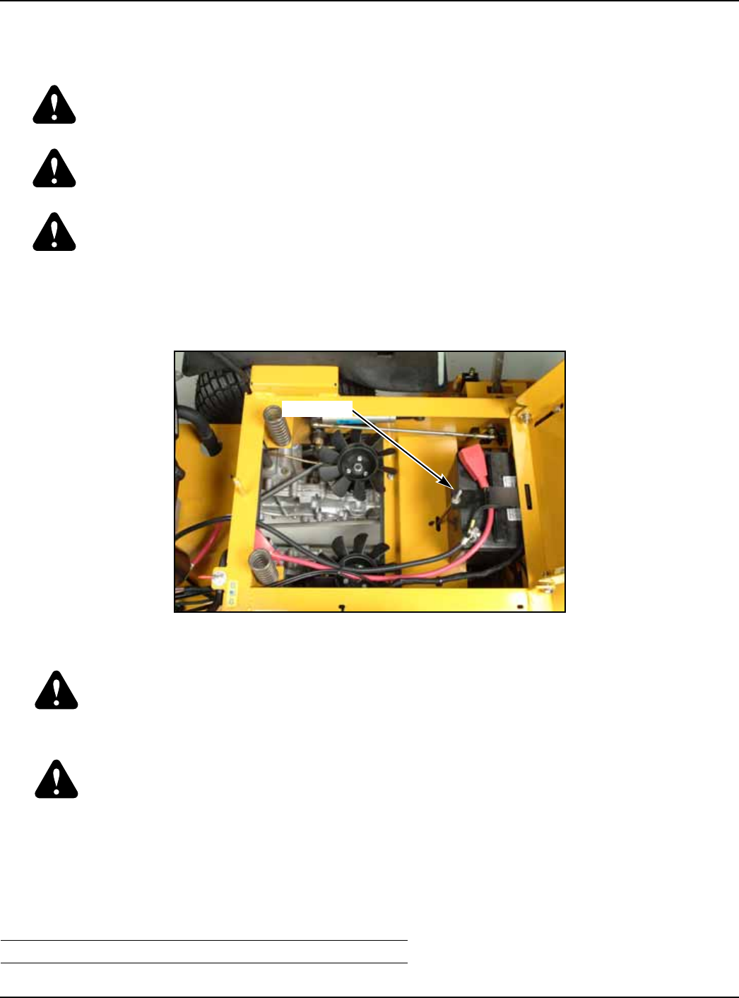
The Battery is located under the seat platform (FIG. 2).
WARNING: Battery post, terminals, and related accessories contain lead and lead compounds–
chemicals known to the State of California to cause cancer and reproductive harm. Wash hands
after handling.
WARNING: Change batteries in an open well ventilated area, away from spark and flames.
Unplug charger before connecting or disconnecting from the battery. Wear protective clothing and
use insulated tools.
WARNING: Avoid skin and clothing contact with battery acid. Always wear eye protection when
checking the battery, acid can cause serious injury to skin and eyes. If contact occurs, flush area
with clean water and call physician immediately. Acid will also damage clothing. Do not drink the
battery electrolyte. Do not allow open flame near the battery when charging. Hydrogen gas forms
inside the battery. This gas is both toxic and flammable and may cause an explosion if exposed to
flame. Always remove the negative ground first and replace it last. Do not overfill battery.
Electrolyte may overflow and damage paint, wiring or structure. When cleaning the battery, use
soap and water. be careful not to get soap and water into the battery. Clean the battery terminals
with a solution of four parts water and one part baking soda when they become corroded.
WARNING: Shorts caused by battery terminals or metal tools touching metal tractor
components can cause sparks. Sparks can cause a battery gas explosion which will result in
personal injury. Prevent the battery terminals from touching any metal tractor parts when removing
or installing the battery. Do not allow metal tools to short between the battery terminals and metal
tractor parts.
WARNING: Incorrect battery cable routing could cause damage to the tractor and battery
cables. This can cause sparks which can cause a battery gas explosion which will result in
personal injury. Always disconnect the negative (black) battery cable before disconnecting the
positive (red) cable.
Common circuit failures are usually caused by shorting, corroded or dirty terminals, loose connection,
defective wire insulation or broken wires. Switches, solenoids and ignition components may also fail, causing
a shorted or open circuit.
The electrical system is protected by fuses located on the right fuel tank instrument panel FIG. 3). The
fuses are as follows:
Before attempting any failure diagnosis of the electrical system, use a test light or voltmeter to check the
FIG. 2
Main 20 amp, blade type
Clutch/Aux 10 amp, blade type
BATTERY
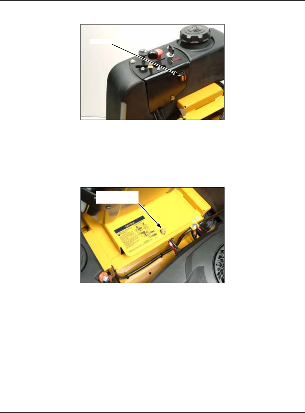
333559 09/08 9-11
battery voltage. If the battery voltage is satisfactory, check the cleanliness and tightness of the terminals and
ground connections. A general understanding of electrical servicing and use of basic test equipment is neces-
sary for troubleshooting and repair.
Major overhaul or repair of the starting motor or charging system should be performed by trained techni-
cians only.
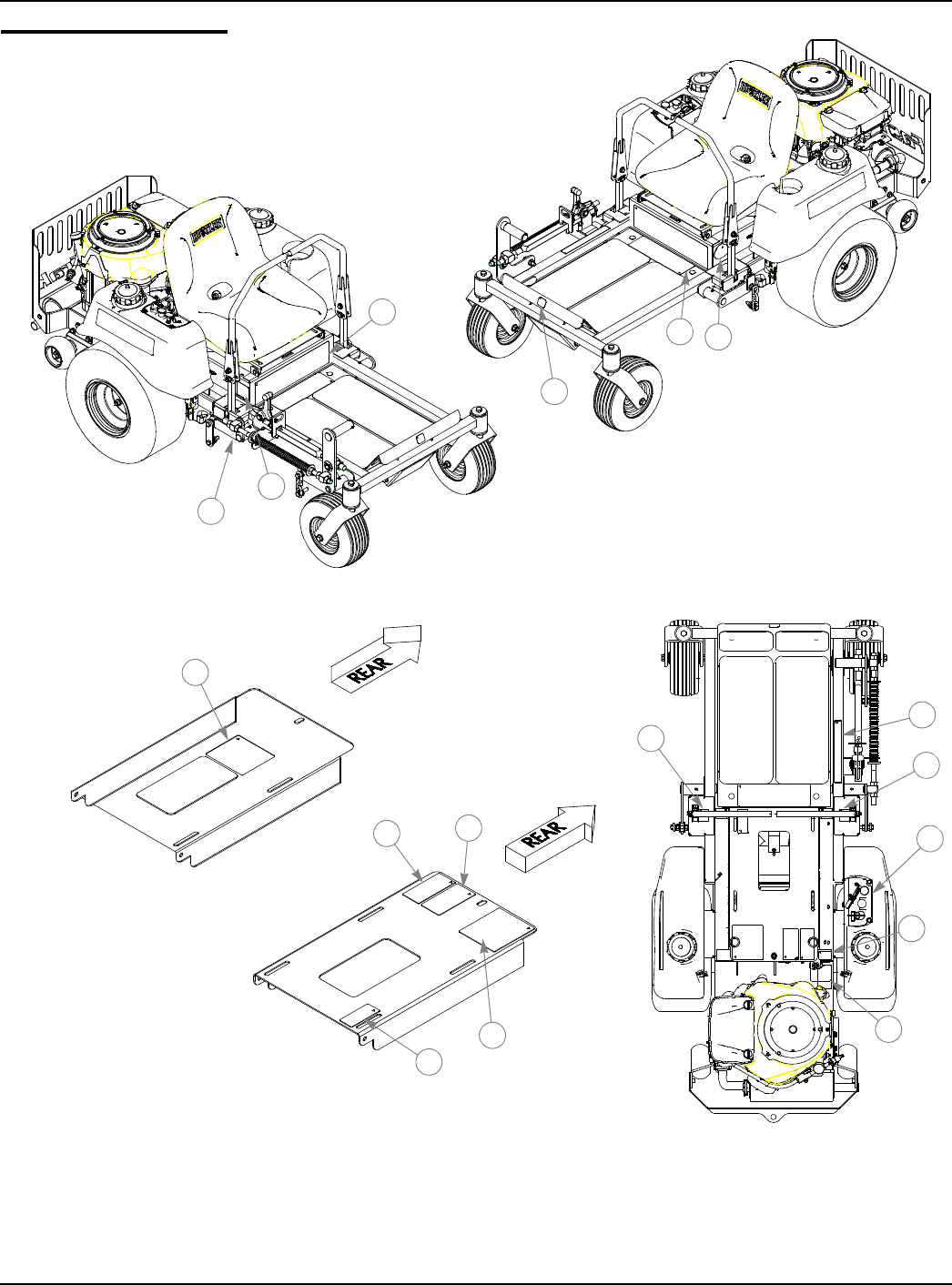
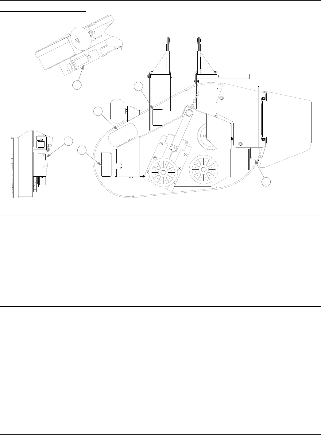
Access to integrated pump/motor units
The integrated pump/motor units are accessed by lifting the seat platform. The seat platform is hinged at
the front. The seat platform is hinged at the front. To raise it, remove the lock nut and flat washer and tilt seat
platform up and forward (FIG. 4).
If the seat is equipped with the optional arm rest kit, make certain to place the control arms in the park
brake position and pivot the arm rests upward before placing the seat platform in the full forward position to
prevent damage to the arm rests.
Hydraulic system
FIG. 3
FIG. 4
FUSES
LOCK NUT
FLAT WASHER
9-12 333559 09/08
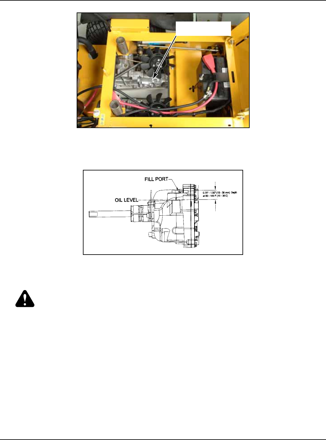
The Hustler FasTrak is equipped with two Hydro-Gear EZT integrated pump/motor transmissions (FIG. 5).
The EZT integrated pump/motor transmission are sealed for life and do not require any scheduled service.
The EZT integrated pump/motor transmissions are filled with 20W50 engine oil. If they ever become low on
oil, fill to the level shown in FIG. 6.
Fuel system
DANGER: Observe usual fuel handling precautions:
Do not smoke while refueling. Extinguish all cigarettes, cigars, pipes and other sources of ignition.
Do not remove fuel cap or fill tank with engine running or while engine is hot. Clean up any gasoline
spills.
Allow engine to cool before storing machine inside a building.
Keep fuel away from open flame or spark and store machine away from open flame or spark or pilot light
such as on a water heater or other appliances.
Use extreme care when handling gasoline and other fuels. They are extremely flammable and vapors
are explosive. A fire or from gasoline can burn you and others and can damage property.
Never refuel or drain the fuel from the machine indoors.
Never attempt to start engine when there is a strong odor of gasoline fumes present. Locate and correct
cause.
Store gasoline in an approved container and keep it out of the reach of children. Never buy more than a
30 day supply of gasoline.
Always place gasoline containers on the ground away from your vehicle before filling.
Do not fill gasoline containers inside a vehicle or on a truck or trailer bed with interior carpets or plastic
bed liners.
Always place gasoline containers on the ground away from your vehicle before filling.
When practical, remove gas-powered equipment from the truck or trailer and refuel the equipment with
its wheels on the ground. If this is not possible, then refuel the equipment on the truck or trailer using a
portable container an not a gasoline dispenser nozzle. If a gasoline dispenser nozzle must be used,
keep the nozzle in contact with the rim of the fuel tank or container opening at all times until fueling is
complete. Do not use a nozzle lock-open device.
FIG. 5
FIG. 6
EZT INTEGRATED
PUMP/MOTOR
333559 09/08 9-13
WARNING: Gasoline is harmful or fatal if swallowed. Long-term exposure to vapors can cause
serious injury and illness. Avoid prolonged breathing of vapors. Keep face away from nozzle and
gas tank or fuel container opening. Keep gasoline away from eyes and skin. If fuel is spilled on
clothing, change clothing immediately.
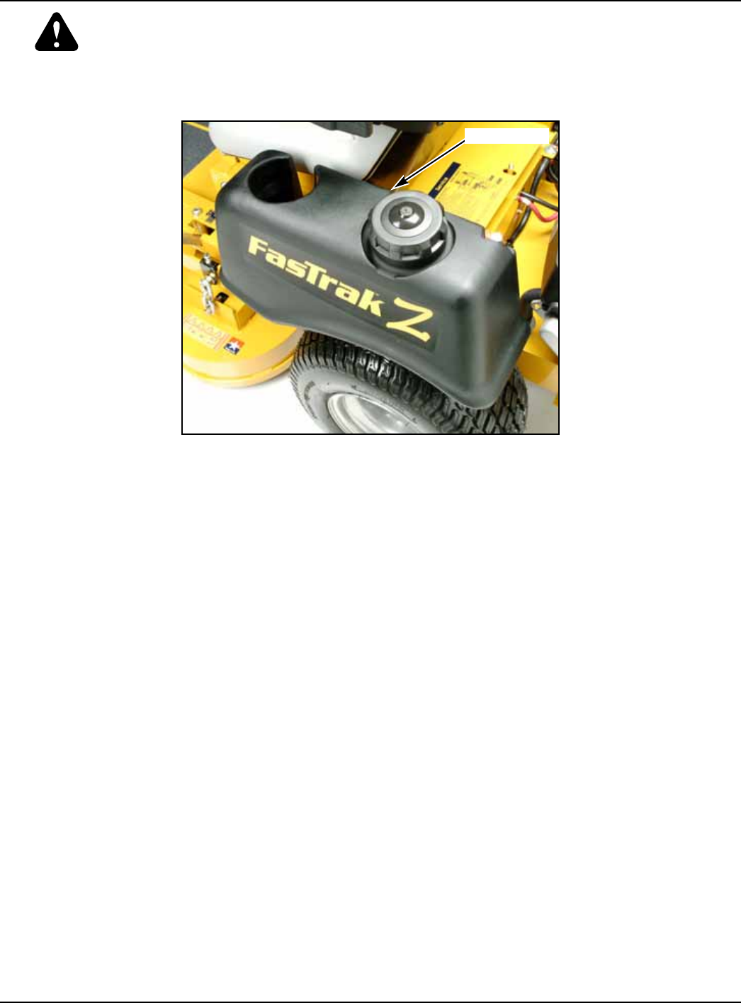
The fuel tanks are located in the tractor’s fenders (FIG. 7). Total capacity for the fuel tanks is 6 U. S. gallons
(22.71 L.).
IMPORTANT: Do not overfill the fuel tanks.The fuel tanks should be filled no higher than 2” below the
tank’s fill neck.When filling the fuel tanks disengage deck clutch, place control levers in park brake
position, and stop tractor engine. Clean around the fuel tank cap and remove the cap and begin filling.
When finished, screw the cap on securely and wipe up any spilled gasoline.
When filling the fuel tanks disengage deck clutch, place control levers in park brake position, and stop
tractor engine. Clean around the fuel tank cap and remove the cap and begin filling. When finished, screw the
cap on securely and wipe up any spilled gasoline.
Use regular unleaded gasoline with an octane rating of 87 or higher.
IMPORTANT: Never use methanol, gasoline containing methanol, or gasohol containing more than
10% ethanol because the fuel system could be damaged. Do not mix oil with gasoline.
Using a fuel stabilizer/conditioner in the tractor can provide benefits such as:
1. Keeps gasoline fresh during storage of 90 days or less. For longer storage, drain the fuel tanks
2. Cleans the engine during operation.
3. Eliminates gum-like varnish buildup in the fuel system.
IMPORTANT: Do not use fuel additives containing methanol or ethanol.
Add the correct amount of gas stabilizer/conditioner to the gas. Follow the gas stabilizer/conditioner man-
ufacturer’s directions for best results.
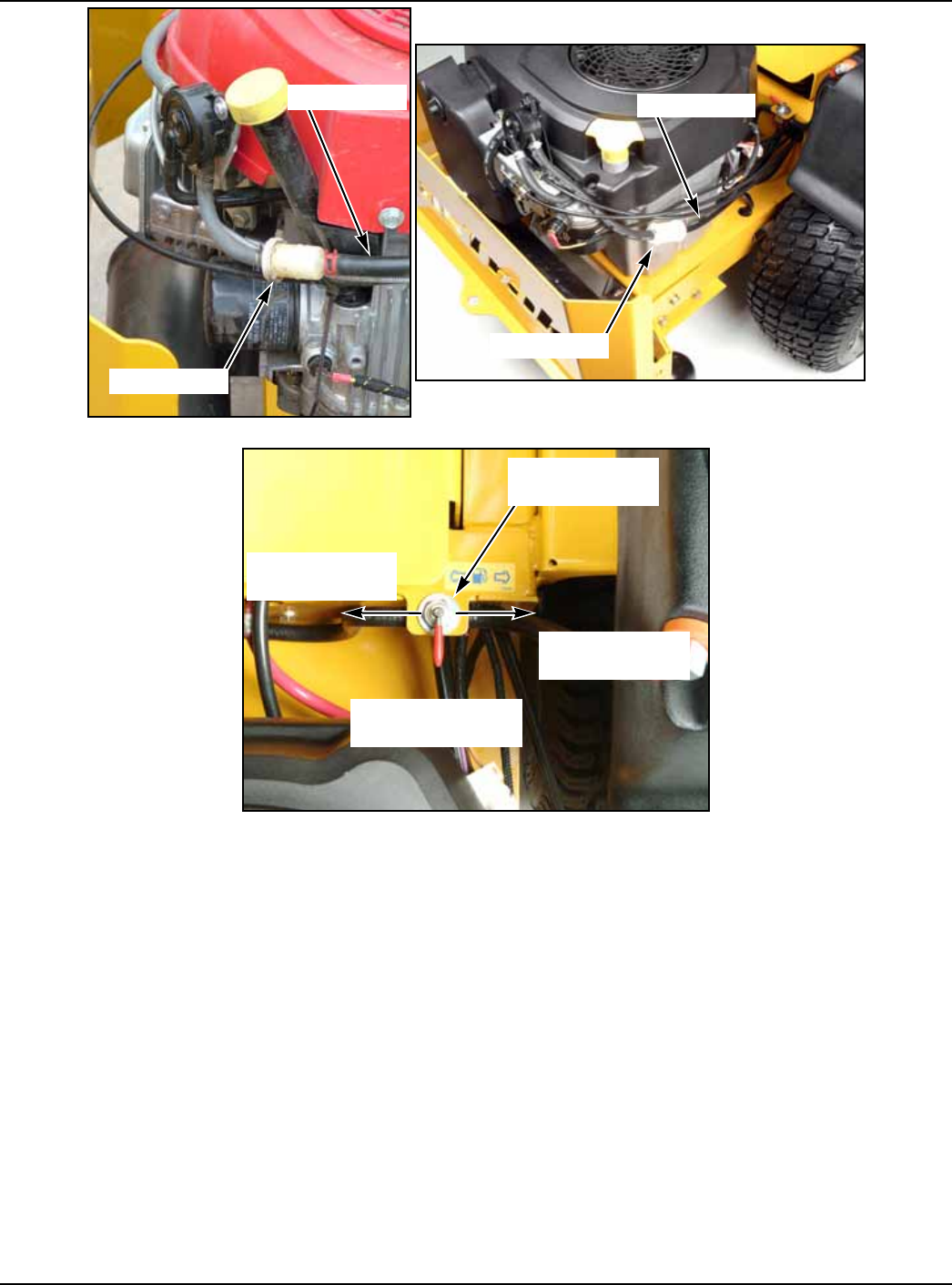
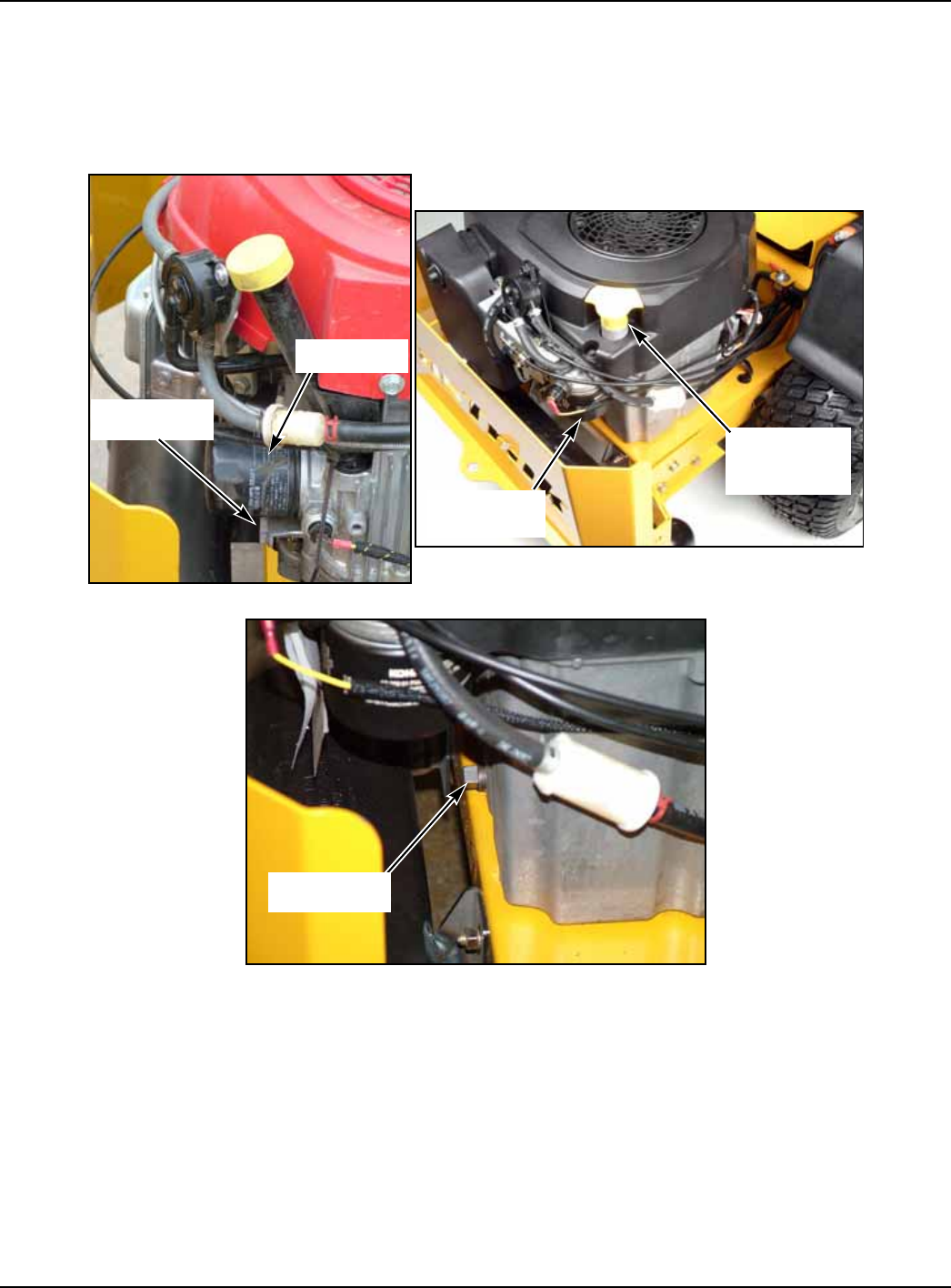
The fuel filter (FIG. 8, & FIG. 9) is installed in the fuel line between fuel tanks and engine fuel pump. Replace
filter annually or after every 100hours of operation, whichever occurs first. For fuel filter removal refer to the
engine owner’s manual.
When replacing the fuel filter, check the fuel line hoses and fuel tank fitting grommets for any cracks or
leaks. Replace as needed. A fuel shut-off valve is located to the right rear of the seat (FIG. 10). Close this valve
(center position) to prevent fuel flow to the engine. Close this valve when transporting the unit on a trailer or
truck.
FIG. 7
FUEL TANK
9-14 333559 09/08
DRAINING THE FUEL TANKS
FasTraks have a fuel shut-off valve (Hustler p/n 7480159) located behind the seat to the right side of the
operator (FIG. 10). Close this valve (center position) to prevent fuel flow to the engine. The valve’s two other
positions are front and rear. To drain a fuel tank equipped with this fuel shut-off valve kit, use the following
method:
1. Park the unit on a flat surface. Stop the engine and remove the ignition key. Make sure deck clutch switch
is IN THE DOWN (OFF) POSITION. Place control levers in the park position. Disconnect negative battery
cable.
2. Close fuel shut-off valve (center position) (FIG. 10.
3. Disconnect the fuel line from the fuel tank fitting. Place the end of the hose in an approved container to
drain the remaining fuel from the hose.
4. Remove the fuel tank from the tractor. Remove the fuel cap, tip the tank and drain the fuel into an approved
fuel container.
5. When fuel tank is drained, re-attach the fuel tank to the tractor andre-connect the fuel line to the fuel tank
fitting. Make certain hose clamp is properly installed.
6. Fill fuel tank with proper grade of gasoline and open shut-off valve.
Engine oil and filter
FIG. 8 HONDA FIG. 9 KOHLER
FIG. 10
FUEL FILTER
INLET HOSE
FUEL FILTER
INLET HOSE
FUEL SHUT-OFF
VALVE
RIGHT FUEL
TANK POSITION
LEFT FUEL
TANK POSITION
CLOSED POSITION
SHOWN
333559 09/08 9-15
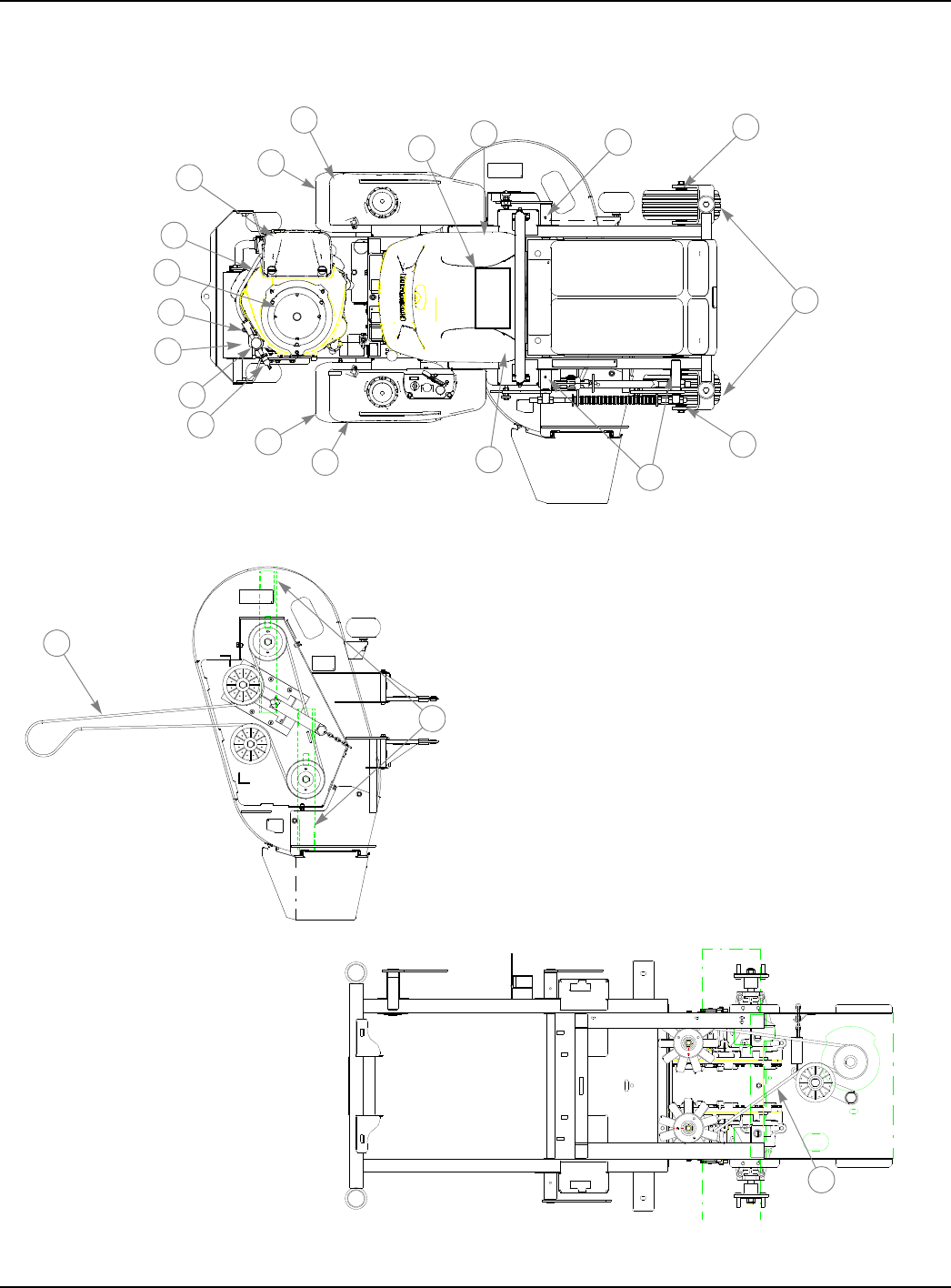
Check engine oil daily and after every 4 hours of operation. Crankcase dipstick and oil filler tube ar located
as shown in FIG. 11 & FIG. 12. Tractor must be setting level when checking oil. Refer to engine manual and
maintenance schedule for oil recommendation and capacities.
Change the engine oil and filter after the first 5 hours of operation, per the engine manufacturer’s recom-
mendations after that. If tractor is being operated in extremely dirty conditions, then it is recommended oil be
changed more frequently.
The oil drain and oil filter are located at the rear of the engine (FIG. 11, FIG. 12, & FIG. 13.
FIG. 11 HONDA FIG. 12 KOHLER
FIG. 13 KOHLER
ENGINE OIL
DRAIN PLUG
ENGINE OIL
FILTER
DIPSTICK &
DIPSTICK & ENGINE
OIL FILLER TUBE
ENGINE OIL
FILLER TUBE
ENGINE OIL
FILTER
ENGINE OIL
DRAIN PLUG
9-16 333559 09/08
Engine mounting bolts
If the original engine mounting bolts are ever removed from the tractor, do not reuse. The original bolts are
self-tapping and if they are re-used they may try to cut new treads into the engine block mounting holes.
Replace with 3/8"-16 x 1.00 Grade 5 bolts. Apply Loc-Tite® 242 to the treads and torque to 30-35 ft.-lbs. Re-use
thin int/ext tooth lockwashers that were factory installed with the original mounting bolts.
Belt replacement
FIG. 14 and FIG. 15 show diagrams and descriptions of the unit’s belt drive systems.
Inspect these belts frequently for wear and serviceability. Replace a belt that shows signs of severe cuts,
tears, separation, weather checking and cracking, or burns caused by slipping. Slight raveling of belt covering
does not indicate failure, trim ravelling with a sharp knife.
WARNING: If the pump belt fails, loss of control will occur especially when operating on a slope.
If you lose steering control while operating the machine, place the steering control levers
in the park brake position immediately. Inspect the machine and involve your Hustler
dealer to resolve the problem before continuing to operate.
Inspect the belt pulley grooves and flanges for wear. A new belt, or one in good condition, should never
run against the bottom of the groove. Replace the pulley when this is the case, otherwise belt will lose power
and slip excessively.
Never pry a bolt to get it on a pulley as this will cut or damage the fibers of the belt covering.
Keep oil and grease away from belts, and never use belt dressings. Any of these will destroy the belt com-
position in a very short time.
Deck belt replacement
1. Park the unit on a flat surface. Stop the engine and remove the ignition key. Make sure deck clutch switch
is in the down (OFF) position. Place control levers in the park brake position. Disconnect negative
battery cable.
2. Place the deck in the lowest position.
3. Remove the deck belt covers.
4. Release the deck belt tension by pulling on the belt tension chain and sliding the chain out of the anchor
DECK BELT DRIVE LAYOUT
1. SPINDLE DRIVE BELT
2. DECK BLADE SPINDLE PULLEY
3. SPINDLE BELT TENSION IDLER
4. SPINDLE BELT TENSION IDLER SPING
(7.5" AT OPERATION)
5. DECK BELT IDLER PULLEY
6. IDLER ARM
FIG. 14
1
2
2
3
4
5
6
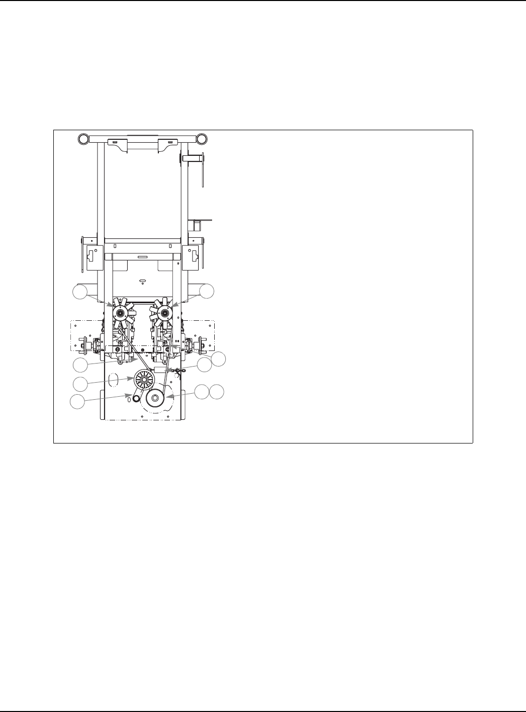
333559 09/08 9-17
bracket slot. This will relieve the tension on the deck belt idler spring (FIG. 14.
5. Pull the idler to the left of the machine to provide maximum belt clearance.
6. Remove the existing belt and replace with a new belt.
7. Route the new belt per FIG. 14.
8. Re-tension the deck belt idler per the Deck drive belt adjustment section located elsewhere in the manual.
9. Re-install the deck belt covers.
10. Re-attach the negative battery cable.
Integrated pump/motor drive replacement
1. Park the unit on a flat surface. Stop the engine and remove the ignition key. Make sure deck clutch switch
is in the down (OFF) position. Place control lever in the park brake position. Disconnect negative battery
cable.
2. Place the deck in the lowest p[osition.
3. Raise the rear of the tractor and block with certified jack stands.
4. Remove the right rear tire and wheel from the tractor.
5. The deck belt must be removed from the clutch pulley first by releasing the deck belt tension by pulling on
the belt tension chain and sliding the chain of the anchor bracket slot. This will relieve the tension on the
deck belt idler sprint (FIG. 14).
6. Remove the deck drive belt from the electric clutch pulley. This belt does not need to be removed from any
of the other pulleys.
7. Release the tension from the integrated pump/motor belt by pulling on the belt tension chain and sliding
the chain out of the anchor bracket slot. (FIG. 17).
8. Slide the belt off the engine pulley The belt will have to be slid above the engine pulley to allow the belt to
be removed from the other pulleys (FIG. 15).
9. Slide the belt over the integrated pump/motor pulleys and fans.
10. The belt can now be removed from above the engine pulley.
11. Install new belt by sliding it up and over the engine pulley. Make certain it is not in the pulley groove at this
time but is above the pulley.
12. Slide the belt over the integrated pump/motor pulleys.
VIEWED FROM
TOP OF UNIT
1. PUMP BELT
2. ENGINE PULLEY
3. PUMP IDLER PULLEY
4. PUMP IDLER ARM
5. PUMP PULLEY
6. ELECTRIC CLUTCH
7. PUMP IDLER SPRING
8. FIXED IDLER PULLEY
FIG. 15
1
2 6
8
5
5
4
3
7
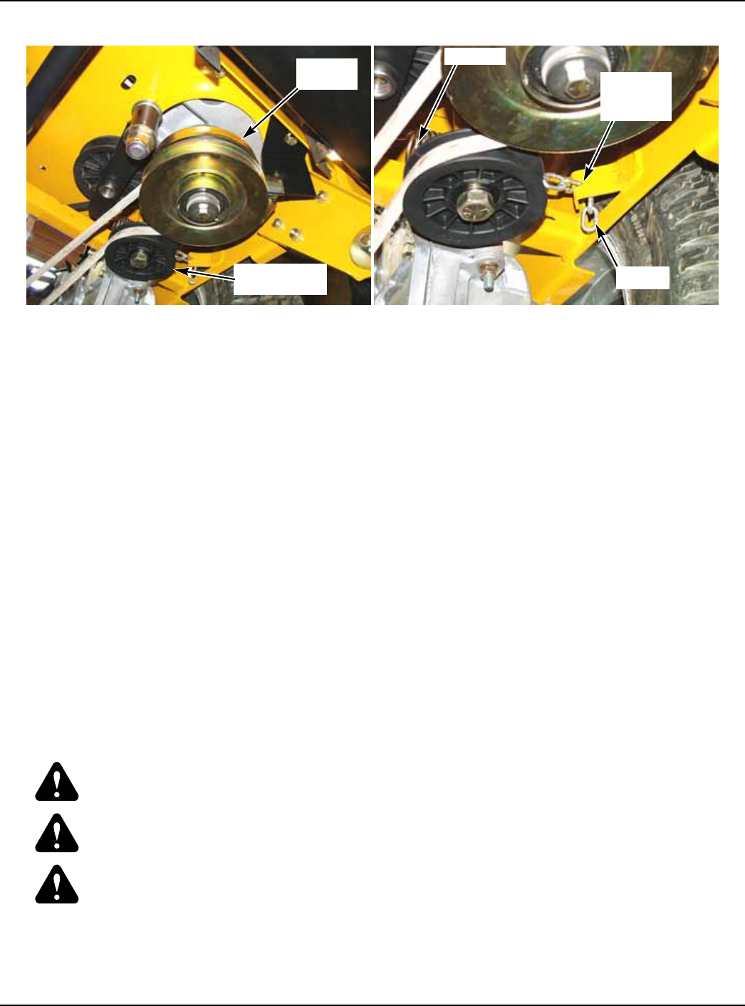
9-18 333559 09/08
13. Slide the belt onto the engine pulley.
14. Slide the belt onto the engine pulley.
15. Re-attach the spring and chain to the tensioner pulley arm. Pull chain and slide the chain into the anchor
bracket slot.)FIG. 17).
16. Re-install the deck drive belt on the electric clutch pulley and make sure it is routed properly on all the deck
pulleys.
17. Re-tension the deck belt idler per the deck drive belt adjustment section located elsewhere in this manual.
18. Re-attach the right rear drive tire and wheel. Torque lug nuts to 65-75 ft.-lbs. (88.14-101.7 NM).
19. Raise the tractor and remove the jack stands. Lower the tractor.
20. Re-attach the negative battery cable.
Mower blade maintenance
Use a 15/16" wrench to remove the 5/8" cap screw holding the blade to the spindle shaft from underneath.
Sharpen the blades on a grinder following pattern as shown (Fig. 9-15).Touch-up sharpening can be done
with a file.
Check the blades for balance following grinding. A commercial balancing tool is available through most
hardware supply stores, or balancing can be done by placing the blade on an inverted line punch or 5/8" bolt.
Blade should not lean or tilt. Spin the blade slowly, blade should not wobble. If blade is out of balance, true it
up before reinstalling.
Lay the blade on a flat surface and check for distortion (Fig. 9-16 and 9-17). Replace any distorted blade.
Do not re-use spindle bolts which have stripped, worn or undercut threads. Torque bolts on spindles to 118
foot-pounds (160.01Nm) when reinstalling blades.
IMPORTANT: The blade sail (curved part) must be pointing upward toward the inside of the deck to
ensure proper cutting.
WARNING: When mounting blades, rotate them after installation to ensure blade tips do not
touch each other or sides of the mower.
WARNING: Failure to correctly torque the bolt may result in the loss of the blade which can
cause serious injury.
WARNING: Mower blades are sharp and can cut. Wrap the blade(s) or wear gloves and use
extra caution when servicing them.
FIG. 16 FIG. 17
ENGINE
PULLEY
DECK IDLER
PULLEY
CHAIN
SPRING
ANCHOR
BRACKET
SLOT
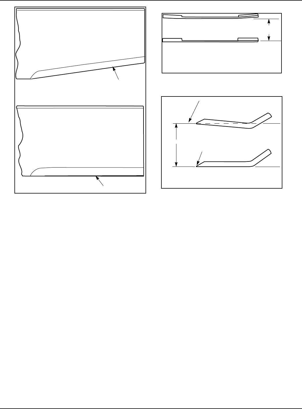
333559 09/08 9-19
FIG. 19
FIG. 20
FIG. 18
Re sharpening
pattern
Do not sharpen to original pattern (below).
It is easier to get a straight cutting edge following
the re sharpening pattern shown above.
Original edge
Warped Blade (Replace)
Straight Blade (Replace)
Comparison of Warped and Straight Blades
Cutting
plane
Cutting edge
Cutting edge
Twisted Blade Edge
(replace)
Straight Blade Edge
End view of blades, comparing
twisted and straightened blades
Cutting Plane

9-20 333559 09/08
Adjustments
Introduction
Your FasTrak 36/42 was adjusted before it left the factory and was checked during pre delivery setup. How-
ever, after start-up and continued use, a certain amount of break-in wear will cause some adjustments to
change.
Remain alert for unusual noises, they could be signaling a problem.Visually inspect the machine for any
abnormal wear or damage. A good time to detect potential problems is while performing scheduled mainte-
nance service. Correcting the problem as quickly as possible is the best insurance.
Clear away heavy build-up of grease, oil and dirt, especially in the engine and under the seat platform
areas; minute dust particle are abrasive to close-tolerance engine and hydraulic assemblies.
Some repairs require the assistance of a trained service mechanic and should not be attempted by
unskilled personnel. Consult your Hustler service center when assistance is needed.
Park Brake Adjustment
Occasionally check the park brake adjustment using the following method:
1. Shut engine off, place control levers in the park brake position, disengage deck clutch,
remove ignition switch key and disconnect negative battery cable before doing any
adjustments.
2. Raise and block the tractor up so the drive wheels are off of the floor.
WARNING: Never work under the machine or attachment unless it is safely supported with jack
stands. Make certain machine is secure when it is raised and placed on the jack stands. The jack
stands should not allow the machine to move when the engine is running and the drive wheels are
rotating. Use only certified jack stands. Use only appropriate jack stands, with a minimum
weight rating of2000 pounds to block the unit up. Use in pairs only. Follow the instructions
supplied with the vehicle stands.
3. Remove the drive tires.
4. Push the steering lever inward into the operating position, disengaging the brake.
Only adjust one side at a time.
5. Locate the brake lever arm and brake gear on the EZT transmission.When the
steering lever is in the operating position, the brake arm should have a minimum of
0.06" (1.52MM) and maximum of 0.125"(3.18MM) clearance between the teeth of the
brake lever arm and the outside diameter of the brake gear (FIG. 21).
6. If you find that the clearance is not to this specification, then adjust the position of the
brake lever arm by moving the lock nuts on the brake rod accordingly. When
adjusting the nuts, the spacing between the inside of the nuts needs to be maintained
at 7/8"(2.22CM) which has been set at the factory. The best way to keep this spacing
is to turn both nuts in the same direction the same number of turns (FIG. 22).
7. Loosen the jam nut on the brake rod and rotate the adjusting tube (FIG. 23) until the
dimensions shown in Fig. 9-18 can be attained.Re-tighten the locknut.
8. After adjustments are made and the proper clearance is restored, actuate and release
the brakes with the steering lever several times.Check to make sure the brake arm on
the EZT is engaging and fully disengaging the teeth of the brake gear.
9. Repeat this process for the opposite side if required.
10. Assemble the rear tires and re-torque the lug nuts to 65-75 ft.-lbs.(88.14-101.7 NM)
11. Raise the rear of the tractor and remove the jack stands. Lower the tractor.
Steering linkage adjustment
The neutral adjustment has been factory adjusted to eliminate creeping when the control levers are in the
neutral position. However, if the steering linkage should ever need adjustment due to the unit creeping
when the steering levers are in the neutral position or the EZT’s whining when the parking brakes are
engaged, take the unit to an Authorized Hustler Dealer for adjustment.
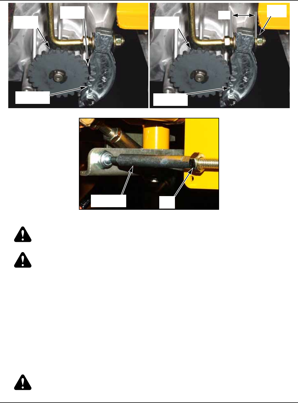
333559 09/08 9-21
WARNING: Only properly trained personnel should attempt to reset the neutral adjustment on
the FasTrak 36/42.This procedure requires that the engine be running and the drive wheels
rotating during adjustment.
WARNING: The adjustable steering rods are located near the EZT integrated pump/motor fans.
Make certain the engine is not running when adjusting the steering rods. The neutral adjustment
for the control levers in the neutral position is discussed in this section.
Control lever neutral adjustment
Before considering any adjustment, check the tire air pressure. Unequal tire pressure will cause the tractor
to drift to one side. Refer to tire pressure information in the Maintenance section of this manual.
NOTE: Proper park brake adjustment must be completed before the control
lever neutral adjustment can be done.
Fine adjustment to the unit’s steering is made with the adjustable pump linkage rods(FIG. 24).
Neutral is properly adjusted when the control levers are in the park brake position and the EZT transmis-
sions do not “whine” .
If this occurs, the control linkage may be adjusted as follows:
1. Raise and block the tractor frame keeping the rear drive tires free and clear of any
obstructions so they are free to rotate. The engine will be running and tires rotating
during this operation.
WARNING: Never work under the machine or attachment unless it is safely supported with jack
stands. Make certain machine is secure when it is raised and placed on the jack stands. The jack
stands should not allow the machine to move when the engine is running and the drive wheels are
rotating. Use only certified jack stands. Use only appropriate jack stands, with a minimum
weight rating of2000 pounds to block the unit up. Use in pairs only. Follow the instructions
FIG. 21 FIG. 22
FIG. 23
BRAKE
GEAR
.06"-.125"
GAP
BRAKE
LEVER ARM
LOCK
NUT
BRAKE
GEAR
BRAKE
LEVER ARM
7/8"
ADJUSTING
TUBE JAM
NUT

9-22 333559 09/08
supplied with the vehicle stands.
2. Remove the seat pan locknut as shown in FIG. 4. Tilt the seat forward. Temporarily
bypass the seat switch.
3. Loosen the front dampener ball stud nut as shown in FIG. 24. The dampener will be
adjusted and tightened after neutral is reset.
4. Staying clear of the rear drive tires, start the engine. If the EZT transmissions whine,
then the neutral setting needs to be re-adjusted.In this operation you will need to
adjust one side at a time. If either side whines significantly, then the steering lever
needs to be pushed into the operating position, disengaging the brake. Most likely
when the brake is disengaged, the drive wheel will begin to rotate even though the
steering lever is in the neutral position.
5. Shut off the machine. Loosen the jam nuts on each end of the pump control rod as
shown in FIG. 24.
6. Start the engine. Move the steering lever to just engage the brake (neutral) slot and
hold it in that position (Do not engage the steering lever far enough to engage the
brakes in the brake slot).
WARNING: This operation is extremely dangerous. Pay close attention when adjusting
the pump control rod so you do not get your fingers, tools, or anything else close to the EZT pump
cooling fans.
7. While holding the steering lever position discussed in step 6,carefully adjust the pump
control rod until the rear wheel starts turning forward. Now turn the pump control rod in
the opposite direction until the moment when the wheel just stops turning forward.
Turn the control rod another 1/2 turn in this direction.Hold the pump rod in this position
and actuate the parking brake with steering lever. The EZT should not whine.
8. Hold the pump control rod still and turn off the engine.
9. Tighten the jam nuts on each end of the pump control rod.
NOTE: Do not let pump control rod turn while tightening the jam nuts.
10. Neutral is now set. Start the engine and actuate the brakes a few times to confirm that
the EZT does not whine when the park brake is set.
11. Repeat for the other side.
12. The steering dampener now needs to be adjusted and tightened.
13. Reconnect the seat switch and make sure the seat switch is operating properly per the
following procedure:
A. The operator must be on the seat when testing the seat switch.
B. Set both control levers in the park brake position.
C. Start the engine and allow it to warm up to operating temperature.
D. With the deck clutch switch down and the control levers in the park brake position, slowly raise off
of the seat. The engine should continue to run.
E. With the deck clutch switch up and/or the control levers in the neutral position, slowly raise off of
the seat. The engine should stop.
F. If the engine fails to stop when the deck clutch switch is up or one or both of the control levers are
not in the park brake position and the operator is off the seat, check the function of the seat switch.
If the seat switch is not operating properly (is not opening or closing) and if the cause can not be
FIG. 24
FRONT DAMPER
BALL STUD
JAM
NUT
PUMP ROD
ADJUSTER ASSEMBLY
JAM
NUT
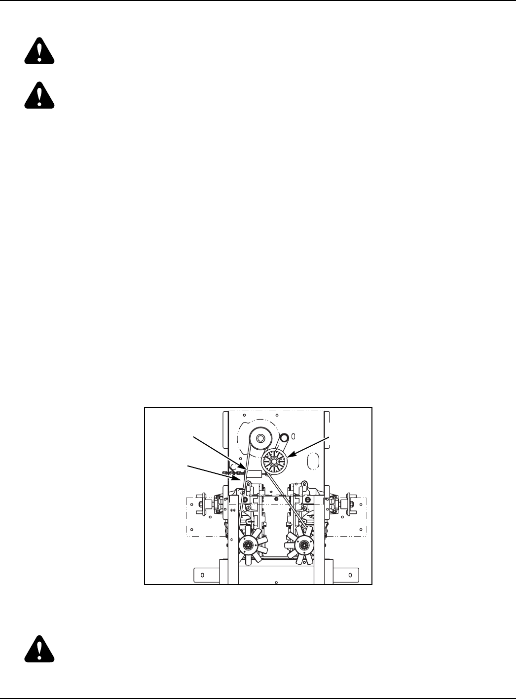
333559 09/08 9-23
determined, replace the seat switch. If the problem can not be located, contact your Hustler
Dealer.
WARNING: The safety interlock system should always function per steps 4 and 5. If it does not
function properly, it should be corrected immediately. Do not operate machine without properly
functioning seat safety switch.
WARNING: Do not operate machine without a properly functioning seat safety switch.
Steering dampener adjustment
The steering dampener is spring loaded to return the control levers to the neutral position from the reverse
position. This gives the operator a sense of neutral during operation.If the steering control lever does not
return to neutral from reverse then adjust as follows:
To set the steering dampeners in the correct operating position follow these steps:
1. Shut engine off, place control levers in the park brake position, disengage deck clutch,
remove ignition switch key and disconnect negative battery cable before doing any
adjustments.
2. If you have not already done so, loosen the front ball stud that is attached to the
forward dampener socket, FIG. 24.
3. When the ball stud is loosened, pull out on the ball stud end and release. The
dampener will return to the neutral position and come to rest. Re-tighten the front ball
stud.
4. Release the park brake and pull the steering lever to the reverse position and allow
the dampener to return the lever to the neutral position. If the steering lever does not
return to the neutral position (centered with the brake slot), then either you have not
adjusted the dampener correctly, or it is damaged and needs to be replaced.
5. Repeat for the opposite side.
Hydraulic pump belt adjustment
The pump drive belt tension remains constant by means of a tension idler and spring (FIG. 25). There is no
tension adjustment of this belt.
NOTE: Inspect the belt every 100 hours and replace as needed.Replace the
belt every 200 hours or every two (2) years whichever comes first.
WARNING: If the pump belt fails, loss of control will occur especially when operating on a slope.
If you lose steering control while operating the machine, place the steering
control levers in the park brake position immediately.Inspect the machine and
involve your Hustler dealer to resolve the problem before continuing to operate.
FIG. 25
SPRING TENSION
IDLER
PUMP
DRIVE
BELT
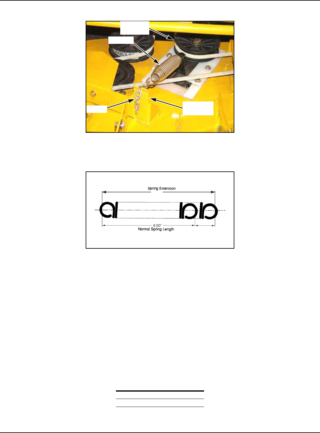
9-24 333559 09/08
Deck drive belt adjustment
The spindle belt tension remains constant by means of a tension idler and spring (FIG. 26). The spring ten-
sion should be such that the belt does not slip under normal operating load conditions, assuming the belt is
not excessively worn or damaged. As belt stretches and wears in, adjustment may become necessary. To
increase belt tension, move the spring chain one (or more) link(s) at the anchor bracket (FIG. 26). Installed
spring length should be 7.50" ± .3) originally with adjustments of .60" per chain link. (FIG. 27).
IMPORTANT: Do not over tension the spring to compensate for a badly worn belt or pulley.
Engine RPM setting
The FasTrak 36/42 is designed so that the engine will run at 3600 rpm (Kohler) or 3550 rpm (Honda) with
integrated pump/motor load only. At this speed the integrated pump/motors are running at their maximum
rated speed.
Deck leveling and height adjustment
The mower deck has three areas that may need to be checked and adjusted periodically. Before consider-
ing any mower deck leveling adjustments, check that the tire air pressure is within the specified range.
DECK LEVEL ADJUSTMENTS
Leveling the deck must be done in the following manner and order:
1. Check tire pressures to make certain they are properly inflated before starting to level
deck. The recommended pressures are as follows:
FIG. 26
FIG. 27
PSI
Drive Tires 8-12
Front Wheels 8-12
TENSION
IDLER
SPRING
CHAIN ANCHOR
BRACKET
7.50”
1.50”
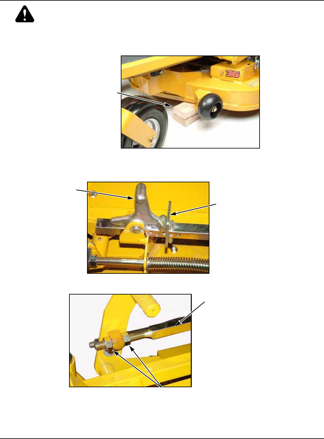
333559 09/08 9-25
WARNING: Stop engine. Make sure deck clutch switch is in the down (OFF) position. Remove
ignition key. Place control levers in the brake position before leaving machine.
2. Park the unit on a flat surface.
3. Raise deck and place 3" tall spacer blocks under the edge of the deck - two in front on
each side and two in back on each side. (FIG. 28). Remove the height adjusting stop
and let the deck down so it rests on the 3" spacer blocks. Make sure the deck is
setting on all four blocks. Leave the height adjusting stop out of the square adjusting
bar for now. The deck should be leveled before the height is set. (FIG. 29)
4. Loosen the two nuts that hold the deck adjusting bar in position. (FIG. 30)
FIG. 28
FIG. 29
FIG. 30
SPACER BLOCKS
HEIGHT ADJUSTING
STOP
HEIGHT
STOP
HANDLE
ADJUSTING BAR
NUTS
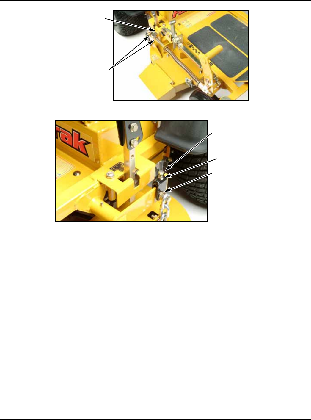
9-26 333559 09/08
5. Loosen the two nuts that hold the right rear deck lifting arm. (FIG. 31)
6. Loosen the left rear deck leveling bracket by loosening the flange nuts. (FIG. 32)
7. Loosen the jam nut and back out the 5/16" bolt on top of the adjuster. (FIG. 32)
8. Check to make sure the deck is resting firmly on all of the 3" blocks. Check the front
right deck chain to be sure it is taut. Now, screw both nuts finger tight against the
square block on the right rear deck lift arm. Tighten these two nuts. (FIG. 31)
9. Tighten the 5/16" bolt on the adjuster until the chain is taut. Tighten the jam nut
against the adjuster. Tighten the two flange nuts. (FIG. 32) The deck should now be
level.
10. To adjust the deck height insert the height adjusting stop into the 3-1/4" position. (FIG.
29)
11. Tighten the rear nut against the block attached to the deck lifting pedal as tight as you
can by hand. (Fig. 3) Make sure the stop handle is pushing firmly against the height
adjusting stop so that there is no free play forward or rearward when you shake the
adjustment bar. (FIG. 30)
12. Finger tighten the front nut against the block attached to the deck lifting pedal. Tighten
both nuts and check to make sure that all deck linkage hardware are tight. (FIG. 30)
13. Raise the deck into transport position and remove the blocks from under the deck
corners. The deck should now be level and the deck cutting height properly adjusted.
FIG. 31
FIG. 32
NUTS
DECK LIFTING
ARM
5/16" BOLT
FLANGE NUTS
JAM NUT

FADFST3642 9/08 i-1
Numerical Index
Part Page
No. No. Part Page
No. No. Part Page
No. No.
Index
Part Numbers
000323 4-11
000331 4-11
005116 6-5, 6-11
005231 4-3
011320 2-4
015495 3-3
015818 4-11
016253 4-3, 4-7
017004 4-7
017129 6-5, 6-11
017616 7-2
019521 5-4
024927 3-2, 3-9, 4-3, 4-7
025007 3-5, 3-7, 6-5, 6-11
025296 3-3, 3-5, 3-7
026237 4-13
028118 3-5, 3-7
029868 3-2
029876 3-9, 4-3
030817 4-7
031997 2-3, 6-3, 6-9
034272 3-3, 3-5, 3-7, 3-9,
4-3, 4-7, 6-3, 6-9
034280 6-3, 6-9, 7-4
036244 4-7, 6-3, 6-9, 7-4
036384 3-5, 3-7
042630 5-2
043570 4-3
044255 4-7
045898 4-13
046821 6-5, 6-11
048553 3-9
050161 4-3
052860 4-3, 4-7, 7-4
053199 2-3, 6-3, 6-9
054502 2-4, 6-3, 6-5, 6-9,
6-11
055749 3-3, 7-2
055822 4-11
055939 3-2
055947 4-13
056077 4-3, 4-7
058776 6-5, 6-11
059832 4-13
059931 6-5
060731 3-9
061077 5-4
061101 3-5, 3-7
064006 6-5, 6-11
068478 1-1
068551 3-9
076422 2-4
079186 3-9, 6-5
083279 8-3
086660 3-9, 6-3, 6-9, 7-4
089789 3-9
104786 4-3
306969 5-2
314989 3-2
315101 3-9
315382 3-9
315440 2-2
315572 6-3
316836 2-3, 4-3, 4-7
316844 2-4
320242 2-2
320267 2-4
320275 7-4
320580 2-3
321042 6-11
321059 4-13
321398 6-5, 6-11
321877 6-5, 6-11
322974 6-3, 6-9
324046 3-5, 3-7
325464 3-9
330225 6-3, 6-9
330274 4-3, 4-7
330324 6-5
330399 6-3, 6-9
334045 3-3
335695 3-5, 3-7
335893 3-5, 3-7
338442 1-1
339689 5-2
344267 2-3, 5-2
348284 3-3
348318 3-3
348458 3-3
352054 3-9
352112 3-9
352500 6-3, 6-9
360131 3-3
360487 3-9
364315 3-5, 3-7, 6-5
378273 4-3
546895 2-2
546911 2-2
546929 6-9
546937 6-3
600221 3-9
600899 8-3
600941 8-3
601156 1-1
601434 6-5
704478 4-7
704643 3-3, 7-2
704932 4-13
705178 3-9
705954 5-2
706531 4-3, 4-7
710087 3-5, 3-7
712257 4-13
712372 4-3, 4-7
712919 3-7
712927 4-3, 6-5, 6-11
712976 5-2
714998 4-13
718288 3-5, 3-9
727016 8-3
727172 8-4, 8-5
739144 4-3, 4-7
740696 3-2
745059 4-11
747303 1-1
756270 3-3
763417 4-7
767954 2-4, 3-9, 4-3, 4-7,
4-11, 6-3, 6-5, 6-9,
6-11, 7-4
767962 2-3, 3-3, 5-2, 6-3,
6-9, 7-2
768044 5-2
768259 3-9
768515 4-3, 4-7, 4-13
768523 3-5, 3-7, 3-9, 4-3,
4-7, 6-3, 6-5, 6-9,
6-11, 7-4
771428 3-2, 4-7
771436 8-3
772806 5-3
772814 5-3
776476 4-13
778365 4-13
779306 4-11
781153 3-5, 3-7
781211 3-9
781229 3-3
781260 3-9
781294 3-3
781302 6-5, 6-11
781567 2-3, 3-9, 5-2, 6-3,
6-9, 7-2
781708 2-3, 6-3, 6-9
781831 3-3

Part Page
No. No. Part Page
No. No. Part Page
No. No.
i-2 FADFST3642 9/08
781872 6-5, 6-11
781880 4-11, 6-3, 6-9
781922 3-9
782474 6-5, 6-11
782573 8-3
782664 4-3
782995 3-3
783134 5-4
783142 5-4
783159 5-4
783506 6-5, 6-11
783514 6-14
783522 6-14
783530 6-14
783548 6-14
783555 6-14
783696 3-9
784223 5-2
784264 5-4
784272 5-4
784280 5-4
784504 6-5, 6-11
784603 5-2
784710 8-3
784827 3-5, 3-7
784918 4-3, 4-7
785030 4-13
785048 4-3, 4-7
785063 3-2
785139 8-3
785147 8-3
785220 8-3
785295 4-11
785394 4-3
785485 2-4
785543 4-3
785808 4-13
785832 6-5, 6-11
786632 3-2
786640 3-2
786657 4-13
787069 6-5, 6-11
787226 1-1
787234 1-1
787242 1-1
787267 4-3
788166 2-3, 6-3, 6-9
788232 3-5, 3-7
788877 3-5, 3-7
788968 8-3
791251 4-3, 4-7
791608 4-3
791723f 3-5, 3-7
792013 3-5, 3-7
792762 4-7
792788 4-7
792796 4-3, 4-7
792895 3-5, 3-7
792911 3-5, 3-7
792929 3-5, 3-7
792945 4-7
792952 4-7
792960 4-11
792978 4-11
792986 4-11
793059 3-9
793083 4-3
793117 4-7
793125 4-3, 4-7
793133 4-7
793141 4-3
793158 4-7
793166 4-3
793174 3-9
793182 3-9
793315 7-4
793331 1-1
793406 5-4
793489 3-2
793505 3-3
793513 8-5
793521 8-4
793547 8-3
793554 8-3
793570 8-4, 8-5
793588 8-3
793612 3-9
793646 3-9
793679 7-4
793687 8-4, 8-5
793703 8-3
793760 4-3, 4-7
793778 6-5, 6-11
793786 6-5
793794 1-1, 6-5, 6-11
793802 1-1, 6-5
793810 4-13
793828 1-1, 6-5
793836 1-1, 3-5, 3-7
793844 2-4
793851 7-4
793869 2-2
793885 4-7
793893 1-1, 6-11
794081 4-11
794172 4-3
794180 4-3, 4-7
794297 8-4, 8-5
794305 8-3
794313 1-1
794370 1-1
794396 3-9
794404 3-5
794503 8-4, 8-5
794545 8-3
794552 3-5
794644 4-3, 4-7
794883 3-9
794974 3-5, 3-7
794982 3-5, 3-7
795005 3-5, 3-7
795013 3-5, 3-7
795021 3-5, 3-7
795039 3-5, 3-7
795047 3-5, 3-7
795054 3-5, 3-7
795062 3-5, 3-7
795229 3-9
795625 3-9
796516 4-7
796615 3-9
797050 3-9
797449 6-5, 6-11
797456 7-4
797753 3-9
797761 3-9
797779 3-9
798363 3-5, 3-7
798371 3-5, 3-7
799221 4-11
808485 6-3, 6-9
808493 2-2, 2-3
927343 1-1
927350 1-1
927368 1-1
927376 1-1
