Hypercom Ice 5700 Users Manual Hardware And Installation Operators
ICE 5700 to the manual 82ad50b8-26df-4ca1-b16c-52d03bdaa9e3
2015-02-09
: Hypercom Hypercom-Ice-5700-Ice-5700-Users-Manual-566050 hypercom-ice-5700-ice-5700-users-manual-566050 hypercom pdf
Open the PDF directly: View PDF ![]() .
.
Page Count: 50

ICE 5700
Hardware and Installation
Operators Manual
Document Revision A
04-04-2001
Hypercom Corporation
2851 West Kathleen Road
Phoenix, Arizona 85053
USA
Corporate Telephone: 602.504.5000
Corporate Fax: 602.866.5380
Corporate Repairs Department: 602.504.5378
Corporate Web Site: www.hypercom.com
Copyright 2001 by Hypercom Corporation.
Printed in the United States of America.
All rights reserved.
This publication is proprietary to Hypercom Corporation and is intended solely for use by Hypercom customers. This
publication may not be reproduced or distributed for any purpose without the written permission of Hypercom Corporation.
The information Hypercom furnishes in this publication is believed to be accurate and reliable. However, the corporation
assumes no responsibility for its use and reserves the right to make changes to the publication at any time without notice.
This document applies to the Name of Software.
Trademarks
Hypercom and the Hypercom logo are registered trademarks of Hypercom Corporation. Integrated Enterprise Network is a
trademark of Hypercom Corporation.
Hypercom has attempted throughout this publication to distinguish proprietary trademarks from descriptive terms by
following the capitalization style the manufacturer uses. Every effort was made to supply complete and correct information.
Any error in identifying or reflecting any proprietary marks or notices is inadvertent and unintentional.
FCC Part 15 (ICES-003)
This equipment has been tested and found to comply with the limits for a Class A digital device, pursuant to Part 15 of the
FCC (ICES-003) Rules. These limits are designed to provide reasonable protection against harmful interference when the
equipment is operated in a commercial environment. This equipment generates, uses, and can radiate radio frequency
energy, and if not installed and used in accordance with the instruction manual, may cause harmful interference to radio
communications. Operation of this in a residential area is likely to cause harmful interference in which case the user will be
required to correct the interference at his own expense.
FCC Part 68 Requirements Notice
This equipment complies with Part 68 of the FCC Rules. On the bottom of this equipment is a label that contains the FCC
Registration Number and Ringer Equivalence Number (REN) for this equipment. If requested, you must provide this
information to your telephone company.
NOTE: REN is not required for some types of analog or digital facilities.
This equipment uses an RJ11 jack.
An FCC-compliant telephone cord and modular plug are provided with this equipment. It is designed to be connected to the
telephone network or premises wiring using a compatible modular jack that is Part 68-compliant. See installation
instructions for details.
The REN is useful to determine the number of devices you may connect to your telephone line and still have all those
devices ring when your telephone number is called. In most but not all areas, the sum of the RENs of all devices connected
to one line should not exceed five. To be certain of the number of devices you may connect to your line, contact your local
telephone company to determine the maximum REN for your calling area.
NOTE: REN is associated with loop-start and ground-start ports. Do not use for E&M or digital ports.
If your telephone equipment causes harm to the telephone network, the telephone company may discontinue your service
temporarily. If possible, they will notify you in advance. However, if advance notice is not practical, you will be notified as
soon as possible. You will be informed of your right to file a complaint with the FCC.
Your telephone company may make changes in its facilities, equipment, operations, or procedures that could affect the
proper functioning of your equipment. If they do, you will be notified in advance to give you an opportunity to maintain
uninterrupted telephone service.
If you experience trouble with this telephone equipment, please contact the Hypercom Repairs Department at (602) 504-
5378 for information on obtaining service or repairs. The telephone company may ask that you disconnect this equipment
from the network until the problem is corrected or until you are sure that the equipment is not malfunctioning.
This equipment may not be used on coin service provided by the telephone company. Connection to party lines is subject
to state tariffs.
This telephone receiver is hearing-aid compatible if applicable.
CTR21
The equipment has been approved to Commission Decision, CTR21, for pan-European single terminal connection to the
Public Switched Telephone Network (PSTN). However, due to differences between the individual PSTNs provided in
different countries, the approval does not, of itself, give an unconditional assurance of successful operation on every PSTN
network termination point. In the event of problems, you should contact your equipment supplier in the first instance.
Industry Canada (IC) Notice
NOTICE: The Industry Canada (IC) label identifies certified equipment. This certification means that the equipment meets
telecommunications network protective, operational, and safety requirements as prescribed in the appropriate Terminal
Equipment Technical Requirements documents. The department does not guarantee the equipment will operate to the
user’s satisfaction.
Before installing this equipment, users should ensure that it is permissible to be connection to the facilities of the local
telecommunications company. The equipment must also be installed using an acceptable method of connection. The
customer should be aware that compliance with the above conditions may not prevent degradation of service in some
situations.
Repairs to certified equipment should be coordinated by a representative designated by the supplier. Any repairs or
alterations made by a user to this equipment, or any equipment malfunctions, may give the telephone communications
company cause to request that the user to disconnect the equipment.
Users should ensure for their own protection that the electrical ground connections of the power utility, telephone lines, and
internal metallic water pipe system, if present, are connected together. This precaution may be particularly important in
rural areas. Caution: Users should not attempt to make such connections themselves, but should contact the appropriate
electric inspection authority or electrician, as appropriate.
“NOTICE: The Ringer Equivalence Number (REN) assigned to each terminal device provides an indication of the
maximum number of terminals allowed to be connected to a telephone interface. The termination on an interface may
consist of any combination of devices subject only to the requirement that the sum of the Ringer Equivalence Numbers of
all the devices does not exceed five.
Warranty and Repair Service Center:
Hypercom Corp.
2851 W. Kathleen Rd.
Phoenix, AZ 85023

Table of Contents
940310-001, rev. A Hypercom Corporation vii
Table of Contents
List of Figures
List of Tables
Introduction
Guide Organization . . . . . . . . . . . . . . . . . . . . . . . . . . . . . . . . . . . . . . . . . . . . . . . . . . . . . . . . . . . . . . . . . . . . . . . . . . . . . . . xiii
Who Should Use This Guide . . . . . . . . . . . . . . . . . . . . . . . . . . . . . . . . . . . . . . . . . . . . . . . . . . . . . . . . . . . . . . . . . . . . . . . . xiii
Other Documentation . . . . . . . . . . . . . . . . . . . . . . . . . . . . . . . . . . . . . . . . . . . . . . . . . . . . . . . . . . . . . . . . . . . . . . . . . . . . . xiii
Guide Conventions . . . . . . . . . . . . . . . . . . . . . . . . . . . . . . . . . . . . . . . . . . . . . . . . . . . . . . . . . . . . . . . . . . . . . . . . . . . . . . . xiv
Chapter 1 Hardware Information
General Safety Precautions . . . . . . . . . . . . . . . . . . . . . . . . . . . . . . . . . . . . . . . . . . . . . . . . . . . . . . . . . . . . . . . . . . . . . . . . . 1-2
Security . . . . . . . . . . . . . . . . . . . . . . . . . . . . . . . . . . . . . . . . . . . . . . . . . . . . . . . . . . . . . . . . . . . . . . . . . . . . . . . . . . . . . . . . 1-3
Keyboard . . . . . . . . . . . . . . . . . . . . . . . . . . . . . . . . . . . . . . . . . . . . . . . . . . . . . . . . . . . . . . . . . . . . . . . . . . . . . . . . . . . . . . . 1-3
PIN Pad . . . . . . . . . . . . . . . . . . . . . . . . . . . . . . . . . . . . . . . . . . . . . . . . . . . . . . . . . . . . . . . . . . . . . . . . . . . . . . . . . . . . . . . . 1-3
Touch-Screen Display . . . . . . . . . . . . . . . . . . . . . . . . . . . . . . . . . . . . . . . . . . . . . . . . . . . . . . . . . . . . . . . . . . . . . . . . . . . . . 1-4
Magnetic Stripe Read Card Reader . . . . . . . . . . . . . . . . . . . . . . . . . . . . . . . . . . . . . . . . . . . . . . . . . . . . . . . . . . . . . . . . . . . 1-4
Check Reader . . . . . . . . . . . . . . . . . . . . . . . . . . . . . . . . . . . . . . . . . . . . . . . . . . . . . . . . . . . . . . . . . . . . . . . . . . . . . . . . . . . 1-4
Thermal Printer . . . . . . . . . . . . . . . . . . . . . . . . . . . . . . . . . . . . . . . . . . . . . . . . . . . . . . . . . . . . . . . . . . . . . . . . . . . . . . . . . . 1-5
Auto Receipt Cutter . . . . . . . . . . . . . . . . . . . . . . . . . . . . . . . . . . . . . . . . . . . . . . . . . . . . . . . . . . . . . . . . . . . . . . . . . . . 1-5
High-Speed Modem . . . . . . . . . . . . . . . . . . . . . . . . . . . . . . . . . . . . . . . . . . . . . . . . . . . . . . . . . . . . . . . . . . . . . . . . . . . . . . . 1-5
Memory . . . . . . . . . . . . . . . . . . . . . . . . . . . . . . . . . . . . . . . . . . . . . . . . . . . . . . . . . . . . . . . . . . . . . . . . . . . . . . . . . . . . . . . . 1-5
Power Requirements . . . . . . . . . . . . . . . . . . . . . . . . . . . . . . . . . . . . . . . . . . . . . . . . . . . . . . . . . . . . . . . . . . . . . . . . . . . . . . 1-5
Dimensions . . . . . . . . . . . . . . . . . . . . . . . . . . . . . . . . . . . . . . . . . . . . . . . . . . . . . . . . . . . . . . . . . . . . . . . . . . . . . . . . . . . . . 1-6
Chapter 2 Installation Procedures
Power-Up the ICE 5700 Terminal . . . . . . . . . . . . . . . . . . . . . . . . . . . . . . . . . . . . . . . . . . . . . . . . . . . . . . . . . . . . . . . . . . . . 2-1
Connecting the Telephone Line . . . . . . . . . . . . . . . . . . . . . . . . . . . . . . . . . . . . . . . . . . . . . . . . . . . . . . . . . . . . . . . . . . . . . . 2-3
Self-Test and Diagnostics . . . . . . . . . . . . . . . . . . . . . . . . . . . . . . . . . . . . . . . . . . . . . . . . . . . . . . . . . . . . . . . . . . . . . . . . . . 2-4
Chapter 3 Setup Procedures
Configuring the ICE Terminal . . . . . . . . . . . . . . . . . . . . . . . . . . . . . . . . . . . . . . . . . . . . . . . . . . . . . . . . . . . . . . . . . . . . . . . 3-1
Program Loading the ICE Terminal . . . . . . . . . . . . . . . . . . . . . . . . . . . . . . . . . . . . . . . . . . . . . . . . . . . . . . . . . . . . . . . . . . . 3-3
Initialize the ICE Terminal . . . . . . . . . . . . . . . . . . . . . . . . . . . . . . . . . . . . . . . . . . . . . . . . . . . . . . . . . . . . . . . . . . . . . . . . . . 3-4
Loading Printer Paper . . . . . . . . . . . . . . . . . . . . . . . . . . . . . . . . . . . . . . . . . . . . . . . . . . . . . . . . . . . . . . . . . . . . . . . . . . . . . 3-5

Table of Contents
viii ICE 5700 Hardware and Installation Operators Manual 940310-001, rev. A
Chapter 4 Wireless POS Terminal Interface
Function Blocks . . . . . . . . . . . . . . . . . . . . . . . . . . . . . . . . . . . . . . . . . . . . . . . . . . . . . . . . . . . . . . . . . . . . . . . . . . . . . . . . . 4-1
Operation . . . . . . . . . . . . . . . . . . . . . . . . . . . . . . . . . . . . . . . . . . . . . . . . . . . . . . . . . . . . . . . . . . . . . . . . . . . . . . . . . . . . . . 4-2
Instructions to the User . . . . . . . . . . . . . . . . . . . . . . . . . . . . . . . . . . . . . . . . . . . . . . . . . . . . . . . . . . . . . . . . . . . . . . . . 4-2
Basic System . . . . . . . . . . . . . . . . . . . . . . . . . . . . . . . . . . . . . . . . . . . . . . . . . . . . . . . . . . . . . . . . . . . . . . . . . . . . . . . . . . . 4-3
Basic System Installation . . . . . . . . . . . . . . . . . . . . . . . . . . . . . . . . . . . . . . . . . . . . . . . . . . . . . . . . . . . . . . . . . . . . . . 4-3
Extending Basic Coverage Area . . . . . . . . . . . . . . . . . . . . . . . . . . . . . . . . . . . . . . . . . . . . . . . . . . . . . . . . . . . . . . . . . 4-4
Installing Extended Basic Coverage Area . . . . . . . . . . . . . . . . . . . . . . . . . . . . . . . . . . . . . . . . . . . . . . . . . . . . . . . . . . 4-5
Large-Area Coverage . . . . . . . . . . . . . . . . . . . . . . . . . . . . . . . . . . . . . . . . . . . . . . . . . . . . . . . . . . . . . . . . . . . . . . . . . 4-6
Installing Large Area Coverage . . . . . . . . . . . . . . . . . . . . . . . . . . . . . . . . . . . . . . . . . . . . . . . . . . . . . . . . . . . . . . . . . . 4-6
Installation Examples . . . . . . . . . . . . . . . . . . . . . . . . . . . . . . . . . . . . . . . . . . . . . . . . . . . . . . . . . . . . . . . . . . . . . . . . . 4-8
Index

List of Figures
940310-001, rev. A Hypercom Corporation ix
List of Figures
Chapter 1 Hardware Information
Figure 1-1. ICE 5700 terminals . . . . . . . . . . . . . . . . . . . . . . . . . . . . . . . . . . . . . . . . . . . . . . . . . . . . . . . . . . . . . . . . . . . . . . 1-1
Figure 1-2. Standard keyboard . . . . . . . . . . . . . . . . . . . . . . . . . . . . . . . . . . . . . . . . . . . . . . . . . . . . . . . . . . . . . . . . . . . . . . 1-3
Figure 1-3. Touch-screen display . . . . . . . . . . . . . . . . . . . . . . . . . . . . . . . . . . . . . . . . . . . . . . . . . . . . . . . . . . . . . . . . . . . . 1-4
Chapter 2 Installation Procedures
Figure 2-1. ICE 5700 power socket . . . . . . . . . . . . . . . . . . . . . . . . . . . . . . . . . . . . . . . . . . . . . . . . . . . . . . . . . . . . . . . . . . . 2-1
Figure 2-2. ICE 5700 line port . . . . . . . . . . . . . . . . . . . . . . . . . . . . . . . . . . . . . . . . . . . . . . . . . . . . . . . . . . . . . . . . . . . . . . . 2-3
Chapter 3 Setup Procedures
Figure 3-1. ICE 5700 printer paper door open . . . . . . . . . . . . . . . . . . . . . . . . . . . . . . . . . . . . . . . . . . . . . . . . . . . . . . . . . . . 3-5
Figure 3-2. ICE 5700 printer paper installation . . . . . . . . . . . . . . . . . . . . . . . . . . . . . . . . . . . . . . . . . . . . . . . . . . . . . . . . . . 3-6
Chapter 4 Wireless POS Terminal Interface
Figure 4-1. Basic configuration . . . . . . . . . . . . . . . . . . . . . . . . . . . . . . . . . . . . . . . . . . . . . . . . . . . . . . . . . . . . . . . . . . . . . . 4-3
Figure 4-2. Extending basic coverage . . . . . . . . . . . . . . . . . . . . . . . . . . . . . . . . . . . . . . . . . . . . . . . . . . . . . . . . . . . . . . . . . 4-4
Figure 4-3. Large area coverage . . . . . . . . . . . . . . . . . . . . . . . . . . . . . . . . . . . . . . . . . . . . . . . . . . . . . . . . . . . . . . . . . . . . . 4-6
Figure 4-4. Premises wiring diagram . . . . . . . . . . . . . . . . . . . . . . . . . . . . . . . . . . . . . . . . . . . . . . . . . . . . . . . . . . . . . . . . . . 4-7
Figure 4-5. Basic system example . . . . . . . . . . . . . . . . . . . . . . . . . . . . . . . . . . . . . . . . . . . . . . . . . . . . . . . . . . . . . . . . . . . . 4-8
Figure 4-6. Extended basic example . . . . . . . . . . . . . . . . . . . . . . . . . . . . . . . . . . . . . . . . . . . . . . . . . . . . . . . . . . . . . . . . . . 4-9
Figure 4-7. Large area example . . . . . . . . . . . . . . . . . . . . . . . . . . . . . . . . . . . . . . . . . . . . . . . . . . . . . . . . . . . . . . . . . . . . 4-10

List of Tables
940310-001, rev. A Hypercom Corporation xi
List of Tables
Chapter 1 Hardware Information
Table 1-1. Terminal dimensions . . . . . . . . . . . . . . . . . . . . . . . . . . . . . . . . . . . . . . . . . . . . . . . . . . . . . . . . . . . . . . . . . . . . . 1-6
Chapter 2 Installation Procedures
Table 2-1. Self-test and diagnostics with software loaded . . . . . . . . . . . . . . . . . . . . . . . . . . . . . . . . . . . . . . . . . . . . . . . . . . 2-4
Table 2-2. Memory page states . . . . . . . . . . . . . . . . . . . . . . . . . . . . . . . . . . . . . . . . . . . . . . . . . . . . . . . . . . . . . . . . . . . . . . 2-4
Table 2-3. Self-test and diagnostics when software is not loaded . . . . . . . . . . . . . . . . . . . . . . . . . . . . . . . . . . . . . . . . . . . . 2-5

940310-001, rev. A Hypercom Corporation xiii
Introduction
The ICE 5700 Hardware and Installation Operators Manual is a comprehensive guide to working with
Hypercom® ICE 5700 terminal.
The ICE 5700 terminal is part of the Hypercom Interactive Consumer Environment (ICE) family of
touch-screen-based terminals and peripherals. All ICE terminals support traditional terminal functions
as well as PIN pad and signature capture functionality. The ICE family employs a modular concept.
The basic ICE unit is a multifunction peripheral for either a T7x terminal or ECR. With its printer and
modem module attached, it becomes a fully-functional terminal and PIN pad.
Guide Organization
The guide contains the following chapters:
Chapter 1, Hardware Information: General descriptions of hardware required to operate the
ICE 5700 terminal
Chapter 2, Installation Procedures: Step-by-step instructions for starting the ICE 5700
terminal
Chapter 3, Setup Procedures: Step-by-step instructions for procedures including
configuration, program load, initialization, and paper loading
Chapter 4, Wireless POS Terminal Interface: Descriptions and step-by-step instructions for
operating the 900 MHz wireless POS terminal interface
Who Should Use This Guide
This guide is intended for network administrators-merchants-operators-technicians or those who
oversee the configuration and daily maintenance of the various networks.
Other Documentation
When working with the ICE 5700 terminal, the ICE 5000 PIN Pad Loader Operators Manual may be
useful as reference material.

Introduction
xiv ICE 5700 Hardware and Installation Operators Manual 940310-001, rev. A
Guide Conventions
This section provides information to help you understand the procedures and concepts presented in
this guide. The following special terms and style conventions are used throughout this document:
Component names: Special bold text highlights certain items including the names of window and dialog
box components. This text appears in instructions for specific actions such as clicking buttons, typing
in text boxes, and selecting from lists. For example:
From the Main tab page of the Group Definition dialog box, click List.
Emphasis: Emphasis is indicated by indented text. For example:
NOTE: A note contains neutral or positive information supplementing the main text. It is often information
that applies only to special cases.
IMPORTANT: Important statements draw attention to information crucial to using the product successfully.
Pay special attention to Important statements.
Procedures: Numbered procedures have a special graphic appearing in the margin of the text. The
words Step-by-Step also appear in bold at the beginning of the procedure. For example:
Step-by-Step
To perform a procedure:
1. Follow the steps outlined in the procedure.
2. Most procedures have at least two steps.
a. This is a substep.
b. Substeps must be completed in the order given.
Clicking with the mouse: This document assumes you are using a mouse or some other pointing device
to move within and among windows and dialog boxes. Therefore, when instructions include clicking
an item, it means you use the mouse to move the cursor onto the desired item. You then click the
mouse button to highlight the item or cause an action to occur. For example:
Click the Totals check box to activate the online totals feature.
Step Action Terminal response
1 Follow the steps outlined in the procedure.
2Most procedures have at least two steps.
Introduction
940310-001, rev. A Hypercom Corporation xv
Series of actions: The greater-than sign (>) appears in procedures indicating a series of simple, related
actions using the mouse pointer. The resulting action typically starts a utility or opens a dialog box.
For example
From the Term-Master main menu, click Network > Definitions’.
Caution and Warning boxes: When you see a Caution or Warning message, read the information
promptly and carefully before proceeding. The formats for the boxes follows.
CAUTION
Caution advises that a negative result such as a loss of data may occur.
WARNING
Warnings provide information that is essential to the safety of the user, the equipment, or both. Failure
to do as instructed may result in physical damage.
Chapter 17
Hardware Information
This chapter provides important information to properly set up and test both the ICE 5700 terminal. To
prevent damage to the POS terminal and possible personal injury, be sure to read this document
before installing an ICE terminal.
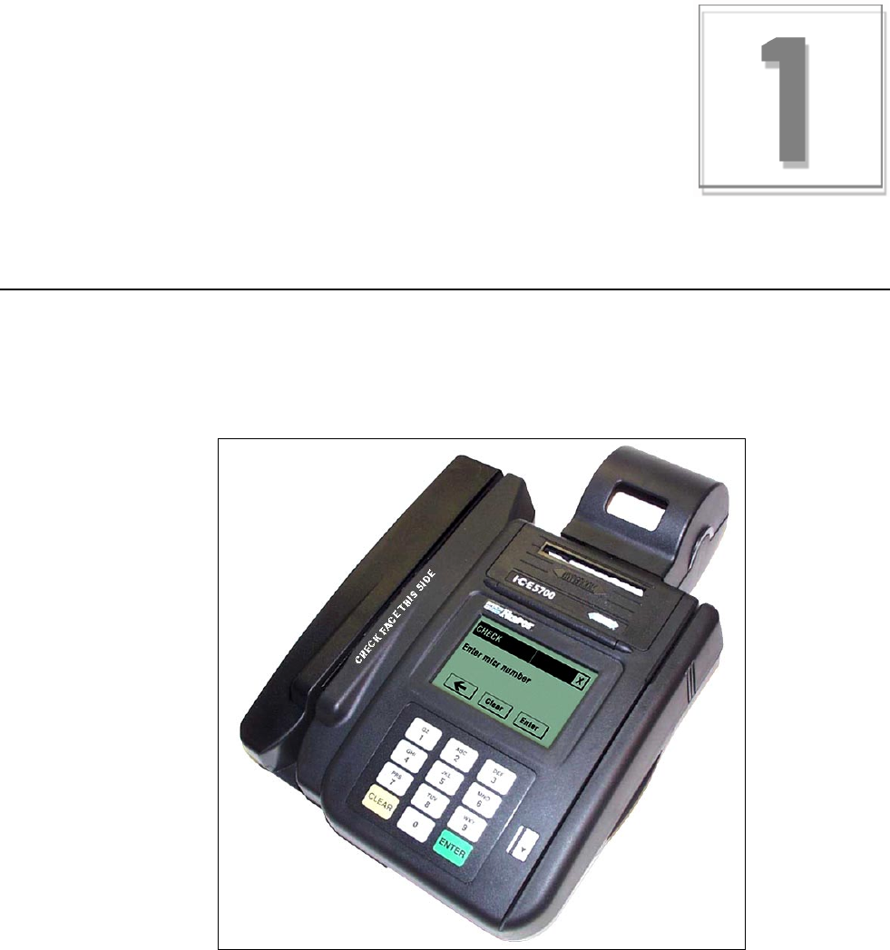
Figure 1-1. ICE 5700 terminal
Chapter 1
1-2 ICE 5700 Hardware and Installation Operators Manual 940310-001, rev. A
General Safety Precautions
This section describes general safety precautions that must be followed to ensure proper installation
and maintenance of the POS product family.
CAUTION
Electrical Safety: Observe all normal electrical safety practices when operating any equipment attached to
an active power source.
Authorized Service: Only a Hypercom authorized service technician or an authorized repair station can
perform equipment servicing, adjustment, maintenance, or repairs on the POS products.
Electrostatic Damage: Before performing any maintenance on POS products, ensure that you wear a
static strap and are grounded to the POS products.
To ensure protection of the telecommunications port against lightning damage, this product requires
connection to the building protective earthing. Therefore, the integrity of protective earthing must be
ensured. Use only the Hypercom provided power supply and power cord. Ensure that power is supplied
from a suitable power outlet to the supply when the terminal is connected to the telephone line.
WARNING
Electromagnetic Compatibility: This is a Class A product. In a domestic environment, this product may
cause radio interference, in which case the user may be required to take appropriate measures.
Danger of explosion: If the battery is installed incorrectly, it could explode. Replace only with the same or
equivalent type recommended by the manufacturer. Dispose of used batteries according to the
manufacturer instruction.
Hardware Information
940310-001, rev. A Hypercom Corporation 1-3
Security
Tamper resistance is provided through the use of intrusion detectors and a secure CPU/RAM module
that is housed in a sealed metal case. PIN encryption, MAC-ing, encryption key storage, and
management are performed in a separate secure co-processor with its own internal RAM. The ICE 5700
terminal supports as many as four integrated Security Access Modules (SAMs) for various smart card
solutions.
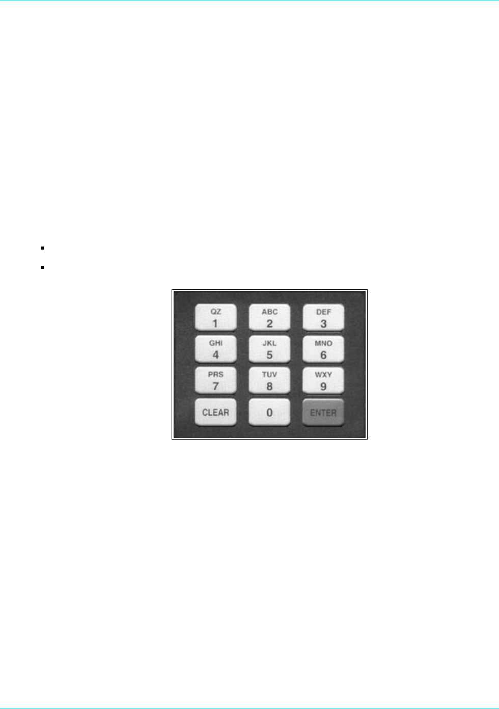
Keyboard
The keyboard consists of 12 keys: 10 numeric and 2 control keys.
The keyboard provides:
Buttons sized to meet various cardholder needs
Audible signals that notify the cardholder of the action being taken
Figure 1-2. Standard keyboard
PIN Pad
The ICE 5700 is a terminal and a PIN pad. The terminal contains all the necessary security features
required for secure PIN encryption and message authentication. By allowing transaction entry and PIN
entry through the same device, the ICE 5700 reduces cost and footprint. Additionally, the ICE 5700
features a touch-screen. This allows the customer to activate complex applications.
Chapter 1
1-4 ICE 5700 Hardware and Installation Operators Manual 940310-001, rev. A
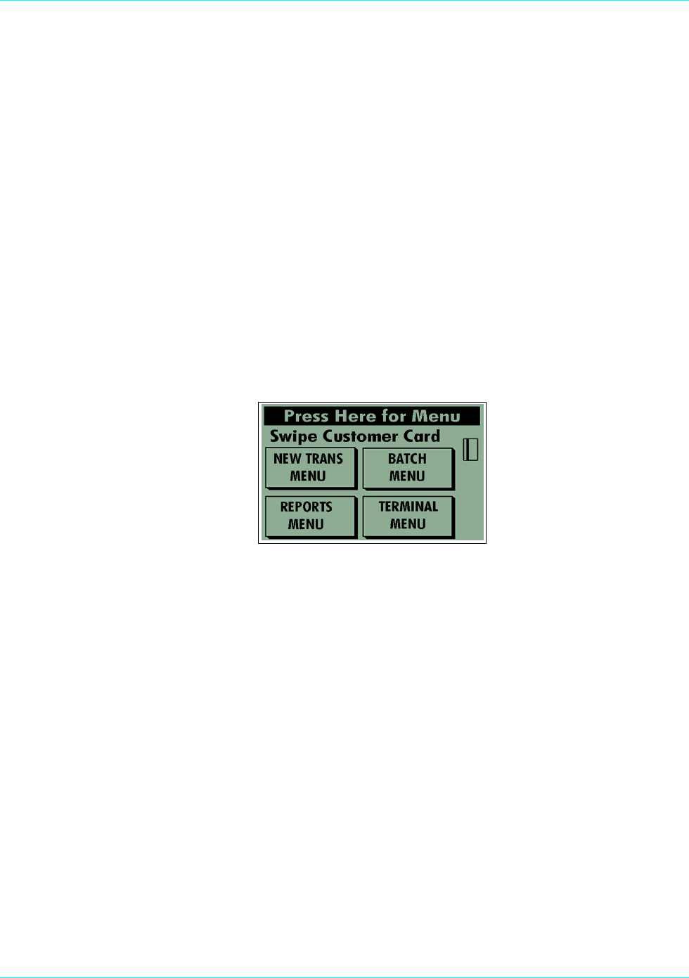
Touch-Screen Display
The ICE 5700 terminal is built around a graphic touch-screen that provides a high degree of flexibility
and an intuitive user environment. Additionally, the graphics screen can deliver advertising and other
promotional messages directly to the consumer.
The easy-to-operate nature of the touch-screen reduces the need for cashier training. It allows trouble-
free operation by consumers in the PIN pad and signature capture pad modes. It also allows the support
of complex new applications such as loyalty, which on a traditional terminal requires many keystrokes
and long transaction entry times.
For operation in dimly lit environments such as restaurants, the screen is equipped with a backlight.
The standard configuration for the ICE 5700 terminal includes a 1.7 inch by 2.7 inch graphic dot matrix
touch screen that is capable of character, graphics, and signature display. While in character mode, the
display resolution is 160 pixels by 80 pixels. The character display has 10 lines with 26 characters for
each line. Graphic keys displayed on the screen initiate most functions.
NOTE: This display is configurable.
Figure 1-3. Touch-screen display
Magnetic Stripe Read Card Reader
The ICE 5700 magnetic stripe read (MSR) card reader uses Track 1 and 2. Track 3 is optional.
Check Reader
The ICE 5700 motorized check reader magnetically reads the MICR line at the bottom of checks. The
terminal supports dial-up to multiple check processors to perform check verification against negative
files or check guarantee by obtaining positive online authorization.

Hardware Information
940310-001, rev. A Hypercom Corporation 1-5
Thermal Printer
The ICE 5700 terminal integrates a high-speed, six lines per second, thermal printer that provides quiet
and trouble-free operation. Since the thermal printer does not use a ribbon, its support requirement is
reduced. The small number of moving parts results in improved reliability.
The thermal paper allows high-quality printing with a long receipt life. When using the correct paper,
receipt life or the time before fading exceeds five years.
Auto Receipt Cutter
The most troublesome component of any POS terminal is the printer. The auto receipt cutter on the ICE
5700 is designed to eliminate the need to manually tear the receipt. The first receipt prints and cuts,
then the second receipt prints and cuts. Users do not have to manually tear the paper from the terminal,
eliminating paper jams.
High-Speed Modem
The ICE 5700 terminal incorporates the new Hypercom FastPOS™ 9600 bps modem. While fully
compatible with the current 300, 1200, and 2400 bps modems, the FastPOS modem, when working with
a FastPOS network node, provides 9600 bps throughput for transactions, batches, and software
downloading.
FastPOS uses a new technology to achieve 9600 bps throughput and 0.5 second training times at a
cost that is comparable to the cost of 2400 bps modems.
FastPOS results in faster transactions and lower transaction costs. For example, at a 5-cents-per-
minute 800 dial rate, with a 1-second billing interval, a FastPOS transaction costs less than 0.5 cents.
More importantly, FastPOS enables large data blocks to be transmitted without a cost penalty. Many of
the new opportunities created by the touch screen of the ICE 5700 become more practical when high-
speed communications are available.
Memory
The ICE 5700 terminals contain a minimum of 1MB of RAM.
Power Requirements
The power requirements for the ICE terminals are 24VDC, 1A; 85-250 VAC, 50/60 Hz, 15VA.

Chapter 1
1-6 ICE 5700 Hardware and Installation Operators Manual 940310-001, rev. A
Dimensions
The dimensions for the ICE 5700 are shown in the following table:
Table 1-1. Terminal dimensions
Terminals Length Width Height
ICE 5700 9.75 in. 7.5 in. 2.25 in.
Chapter 2
Installation Procedures
This section contains important information that will help properly install ICE 5700 terminal.
Power-Up the ICE 5700 Terminal
Use the following procedures to power up the ICE 5700 terminal.
Step-by-Step
To power up the ICE terminal:
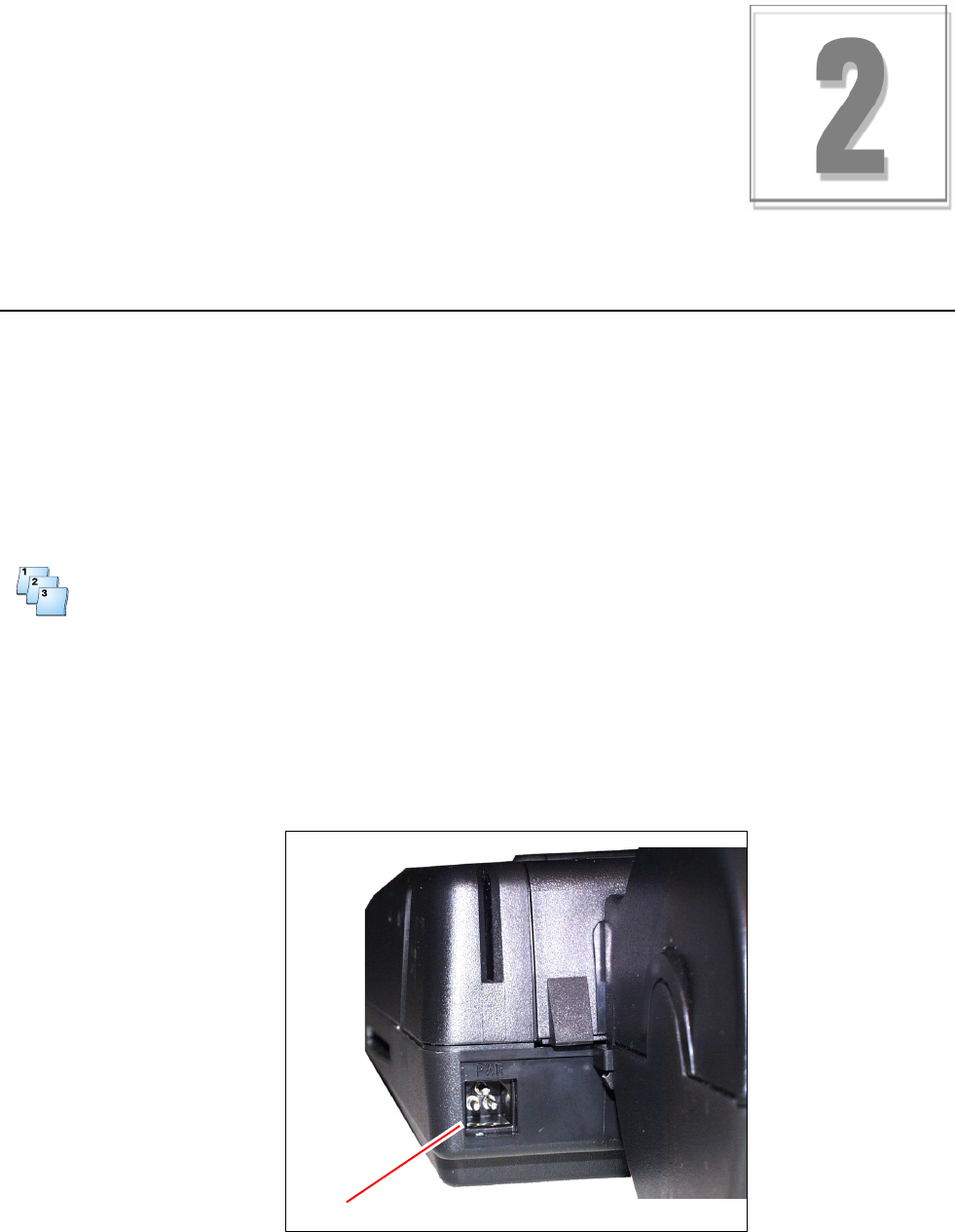
1. Connect the +24 Vdc power cable from the AC Adaptor to the three-pin terminal socket labeled
POWER on the back panel of the ICE 5700 terminal.
2. Plug the AC Adaptor into a 110-Volt grounded power receptacle. Be sure the connector is firmly
seated. When the power is connected successfully, the terminal beeps twice and then performs a
self-test and diagnostic routine.
Figure 2-1. ICE 5700 power socket
Power socket

Chapter 2
2-2 ICE 5700 Hardware and Installation Operators Manual 940310-001, rev. A
WARNING
Disconnect the AC electric power before replacing the printer module.
Do not use an adapter, a power extender adapter, a power extender cable, or an AC outlet that does not
have a ground connection.
Do not disassemble the AC adapter. Only a qualified service technician should service the adapter.
The AC adapter was designed for indoor use only. Do not expose to rain or snow.
Do not immerse in fluid.
The reliability of electronic equipment is significantly reduced when it is powered from an ungrounded
outlet. Power is connected to the terminal through a low-power AC adapter. Connect only one terminal to
each AC adapter.
Installation Procedures
940310-001, rev. A Hypercom Corporation 2-3
Connecting the Telephone Line
Use the following procedures to connect a telephone line to the ICE 5700 terminal.
Step-by-Step
To connect a telephone line:
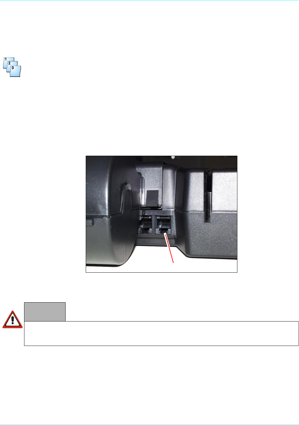
1. Insert the telephone cable shipped with the ICE 5700 terminal into a dedicated analog modular
telephone receptacle. The use of a different cable might result in improper operation.
2. Insert the other end of the telephone cable into the opening labeled LINE on the back panel of the
ICE 5700 terminal.
3. Ensure that the telephone line cable latches are firmly locked into the jack on the ICE 5700
terminal and wall receptacle.
Figure 2-2. ICE 5700 line port
Line port
WARNING
Do not insert the telephone line into the PIN pad port.
Chapter 2
2-4 ICE 5700 Hardware and Installation Operators Manual 940310-001, rev. A
Self-Test and Diagnostics
Immediately after powering up the terminal, a double beep indicates that the terminal has automatically
initiated its self-diagnostic routine.
The software and download status of the terminal is displayed during the self-test, which lasts
approximately four seconds.
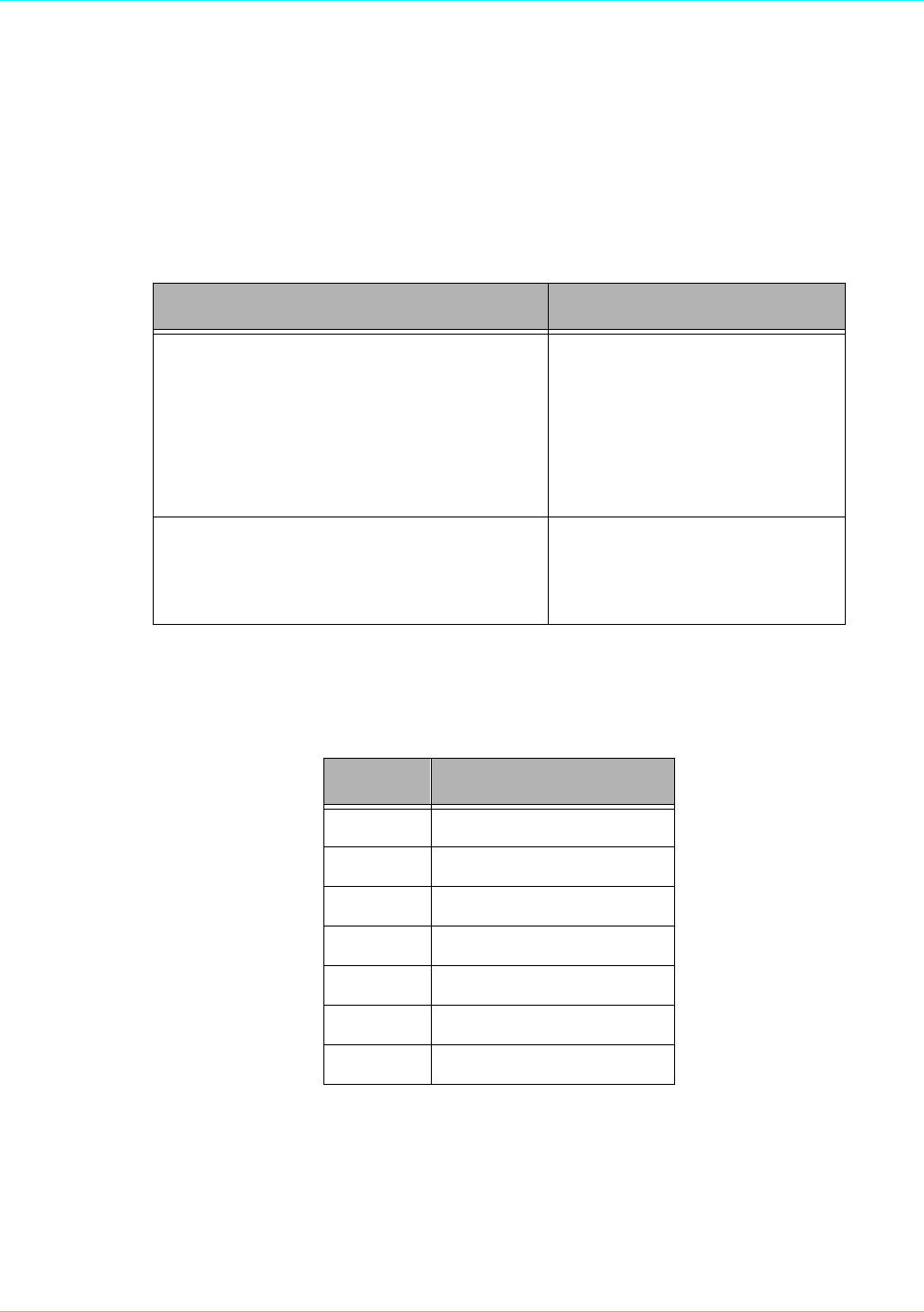
A memory page may be in one of the states shown in the following table.
Table 2-1. Self-test and diagnostics with software loaded
Description Terminal response
Software: Software name and version.
DLL: Tracks the number of downloads. This is
controlled by Term-Master.
OS: Operating System and version.
Terminal: Terminal ID number.
IDENTIFICATION
SOFTWARE XX_XXXXXX
DLL 00
OS T5KBOOTXXX
TERMINAL NNNNNNNN
WAIT SELF TEST
Installed memory is displayed. The display
indicates one megabyte of memory installed.
MEMORY PAGE STATUS:
BOOT: XXXX
01: AAAAAAAAAFFFFFF
17: FFFFFFFFFFFFFF
Table 2-2. Memory page states
Status Description
A Active: application resident
C Corrupt: checksum error
FFree
L Lost Communication
I Inactive
U Unknown
- No fit: not available for use

Installation Procedures
940310-001, rev. A Hypercom Corporation 2-5
If the terminal is not loaded with software, the displays shown in the following table are typical.
Table 2-3. Self-test and diagnostics when software is not loaded
Description Terminal response
T5KBOOT: Boot program name
XXX: Boot program release
T5KBOOTXXX
WAIT SELF TEST
The memory page status indicates that no
program is loaded.
MEMORY PAGE STATUS:
BOOT: XXXX
01: FFFFFFFFFFFFFFF
17: FFFFFFFFFFFFFF
PE indicates Program Error. In this case, the
program is not loaded.
CONFIGURE TERMINAL
or CALL HELP - PE
0: Restart
1: Merchant Programming
2: Program Load
3: Clear Page Memory
4: Maintenance Functions
5: Fast Load

Chapter 3
Setup Procedures
This chapter provides setup procedures for the Hypercom ICE 5700 terminal, including the steps
necessary for terminal configuration, program load, and initialization. Please refer to the ICE 5000
PIN Pad Loader Operators Manual when configuring a terminal for Debit Processing.
Configuring the ICE Terminal
A configuration sets the parameters the ICE 5700 uses to communicate with Term-Master. When the
configuration is complete, the terminal is able to receive the terminal application software.
Step-by-Step
To configure the ICE terminal:
Step Action Terminal response
The Idle prompt appears. CONFIGURE TERMINAL
OR CALL HELP - PE
0: RESTART
1: MERCHANT PROGRAMMING
2: PROGRAM LOAD
3: CLEAR PAGE MEMORY
4: MAINTENANCE FUNCTIONS
5: FAST LOAD
1Touch 1 on the terminal display. MERCHANT PROGRAMMING
TERMINAL ID NUMBER
XXXXXXXXX
Q W E R T Y U I O P
A S D F G H J K L
ÏZ X C V B N M SPACE
CANCEL CLEAR ENTER

Chapter 3
3-2 ICE 5700 Hardware and Installation Operators Manual 940310-001, rev. A
2 Type the terminal ID, then touch Enter on the terminal display,
or press Enter on the terminal keyboard.
MERCHANT PROGRAMMING
INIT. TELEPHONE NO
Ï A B C D E F
CANCEL CLEAR ENTER
3 Type the initialization number, then touch or press Enter.MERCHANT PROGRAMMING
NMS TELEPHONE NO
Ï A B C D E F
CANCEL CLEAR ENTER
4 Type the NMS number, then touch or press Enter.MERCHANT PROGRAMMING
DIAL 0-TONE 1-PULSE
Ï A B C D E F
CANCEL CLEAR ENTER
5Type 0 for tone dialing or 1 for pulse dialing, then touch or
press Enter.
MERCHANT PROGRAMMING
PABX ACCESS CODE
Ï A B C D E F DEL
CANCEL CLEAR ENTER
6 Type a PABX code, if necessary, then touch or press Enter.MERCHANT PROGRAMMING
TERMINAL ID NUMBER
XXXXXXXXX
Q W E R T Y U I O P
A S D F G H J K L
ÏZ X C V B N M SPACE
CANCEL CLEAR ENTER
7 Touch Cancel.The terminal displays
the Idle prompt.
Step Action Terminal response

Setup Procedures
940310-001, rev. A Hypercom Corporation 3-3
Program Loading the ICE Terminal
A program load is required when no software is currently in the terminal. Depending on the software
application, an average program load takes approximately 40 minutes to complete. The initialization
process loads the merchant-specific information in a terminal.
MAC software is required when the ICE 5700 supports debit processing. Please refer to the ICE 5000
PIN Pad Loader Operators Manual for further details.
Step-by-Step
To load a program into the ICE terminal:
Step Action Terminal response
The Idle prompt appears. PLEASE INITIALIZE
OR CALL HELP - PE
0: RESTART
1: MERCHANT PROGRAMMING
2: PROGRAM LOAD
3: CLEAR PAGE MEMORY
4: MAINTENANCE FUNCTIONS
5: FAST LOAD
1 Touch 2 on the terminal display. PROGRAM LOAD
CORRECT? YES OR NO
CANCEL CLEAR ENTER
2 Touch Enter to continue. The following screens appear. PROCESSING YOUR
REQUEST
Please wait and
watch for message
The terminal checks the dial line. CHECKING LINE
The terminal dials the host. WAITING FOR DIAL TONE
DIALING NOW
The terminal waits for the host to answer. WAITING FOR ANSWER
The terminal connects to the host. TRAINING MODEM
The terminal sends request information to the host. PROCESSING NOW
The program load begins. LOADING MEM XX XXXX

Chapter 3
3-4 ICE 5700 Hardware and Installation Operators Manual 940310-001, rev. A
Initialize the ICE Terminal
After the terminal receives a new program load, an initialization is required to start the terminal
operations. In other cases such as a new card type, an initialization is requested to update the terminal
parameters. An initialization takes approximately 30 seconds to complete.
During an initialization, the terminal automatically connects to the initialization host to receive the
downloading of the initialization parameters, known as the terminal profile.
Step-by-Step
To initialize an ICE terminals:
Step Action Terminal response
After a program load, the terminal displays the following
prompt.
MAIN
TERMINAL SETUP
TESTS SUPERVISOR
1 Touch Initialize on the terminal display. INITIALIZE
CORRECT?
YES OR NO
2 Touch Yes. The following screens appear. COMMS
Dialing now
The terminal dials the host. COMMS
Processing now
The terminal sends request information to the host.
Transaction Complete
The transaction is complete. The terminal displays
the Idle prompt.
Setup Procedures
940310-001, rev. A Hypercom Corporation 3-5
Loading Printer Paper
Use the following procedures to install paper in the ICE 5700 terminal.
Step-by-Step
To load the printer paper in the ICE 5700:
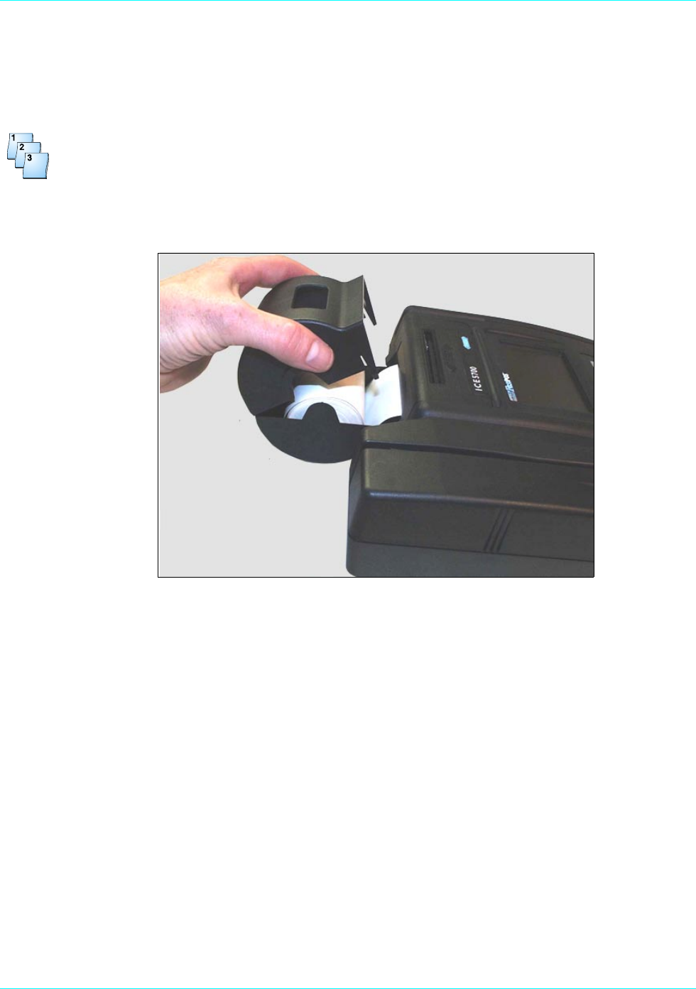
1. Open the printer paper cover on the back of the ICE 5700 printer.
Figure 3-1. ICE 5700 printer paper door open
2. Place the paper roll into the printer paper holder, make sure the printer paper unrolls from under
the roll, not over the top, and has a straight-line path into the printer paper-feed mechanism.
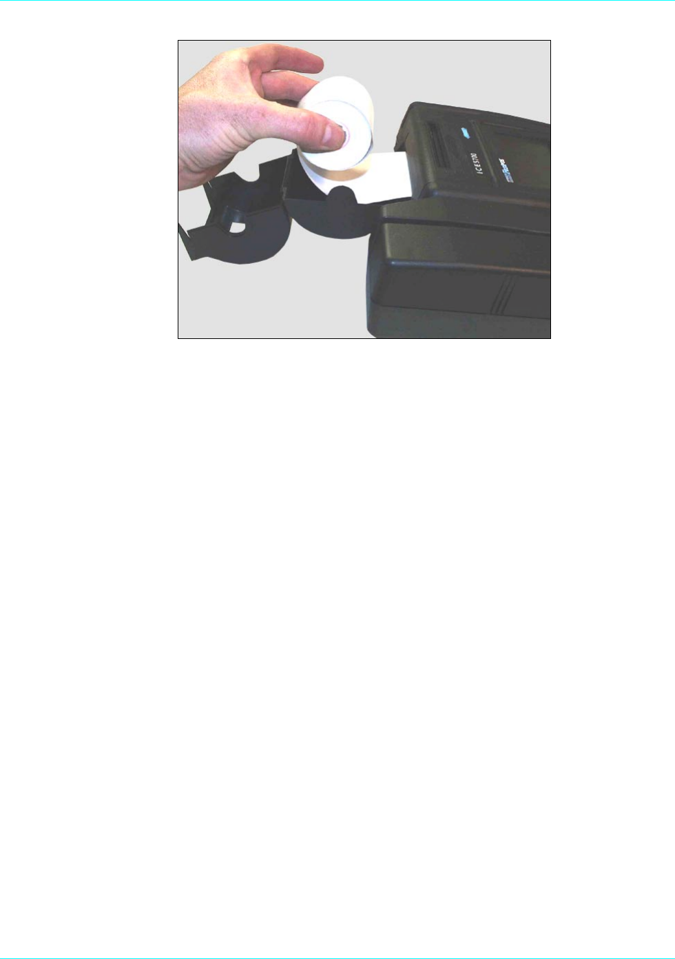
3. Place the end of the paper in the paper guide. The printer then automatically feeds the paper. If
the printer does not automatically feed the paper, proceed with step 4. Otherwise, proceed to step
10.
Chapter 3
3-6 ICE 5700 Hardware and Installation Operators Manual 940310-001, rev. A
Figure 3-2. ICE 5700 printer paper installation
4. At the main terminal display, touch Terminal Menu.
5. Touch the arrow. The Terminal Main menu prompt appears.
6. Touch Setup. The Setup menu appears.
7. Touch Printer. The Printer prompt appears.
8. Touch Paper Feed. The Paper Feed menu appears.
9. Touch Paper Feed until the paper feeds through the printer tear bar.
NOTE: If the printer fails to advance the paper, you may need to check the printer ON/OFF settings.
Complete the following steps to verify the settings.
a. At the main terminal display, touch Terminal Menu.
b. Touch the arrow. The Terminal Main menu prompt appears.
c. Touch Setup. The Setup menu appears.
d. Touch Printer. The Printer prompt appears.
e. Touch On/Off. The Printer Toggle menu prompt appears. The menu displays Printer is
disabled. Enable?.
f. Touch Yes. The terminal changes the printer settings to Enabled and returns to the main
menu. Repeat steps 4 through 9.
10. Touch Quit. The system returns to the main terminal menu.
11. Close the printer paper cover.

Chapter 4
Wireless POS Terminal Interface
The ICE 5700, 900 MHz wireless POS terminal interface system offers a high level of customer
convenience and reduces the time required to process a POS transaction. Because customers see the
process, they have control of the financial transaction and feel an added sense of security. The host
POS terminal and peripheral POS devices provide data encryption.
Function Blocks
The 900 MHz wireless POS terminal interface consists of the following functional blocks:
Terminal transceiver interface: Hypercom model FTI01 or for use with a single terminal
transceiver, a Hypercom adapter cable, P/N 810170-001.
Terminal transceiver: Hypercom model FXV01.
Customer premises wiring: If required.
Peripheral terminal device: This may be any Hypercom POS terminal or POS terminal
accessory such as a PIN pad or electronic receipt capture device, with a compatible optional
wireless transceiver installed. An example is an ICE 4000 POS terminal with appropriate
software installed.

Chapter 4
4-2 ICE 5700 Hardware and Installation Operators Manual 940310-001, rev. A
Operation
The ICE 5700 900 MHz wireless POS terminal interface system is designed to be transparent to the
user. The peripheral device operates with a wireless POS terminal interface system in the same way as
when a cable connection exists between a peripheral POS device and a host POS terminal.
Instructions to the User
This equipment was tested and found to comply with the limits for a class B digital device, pursuant to
part 15 of the FCC Rules. These limits are designed to provide reasonable protection against harmful
interference in a residential installation. This equipment generates, uses, and can radiate radio
frequency energy. If not installed and used in accordance with the instructions, the equipment may
cause harmful interference to radio communications. However, there is no guarantee that interference
will not occur in a particular installation. If this equipment does cause harmful interference to radio or
television reception, determined by turning the equipment off and on, the user is encouraged to try to
correct the interference by one or more of the following measures:
Reorient or relocate the receiving antenna
Increase the separation between the equipment and receiver
Connect the equipment to an outlet on a circuit different from that the receiver is connected to
Consult the dealer or an experienced radio or TV technician for help
This equipment is certified to comply with the limits for a class B computing device, pursuant to FCC
Rules. To maintain compliance with FCC regulations, shielded cables must be used with this equipment.
Operation with non-approved equipment or unshielded cables is likely to result in interference to radio
and TV reception. The user is cautioned that changes and modifications made to the equipment without
the approval of the manufacturer could void user authority to operate this equipment.
This class B digital apparatus meets all requirements of the Canadian Interference-Causing Equipment
Regulations.
Wireless POS Terminal Interface
940310-001, rev. A Hypercom Corporation 4-3
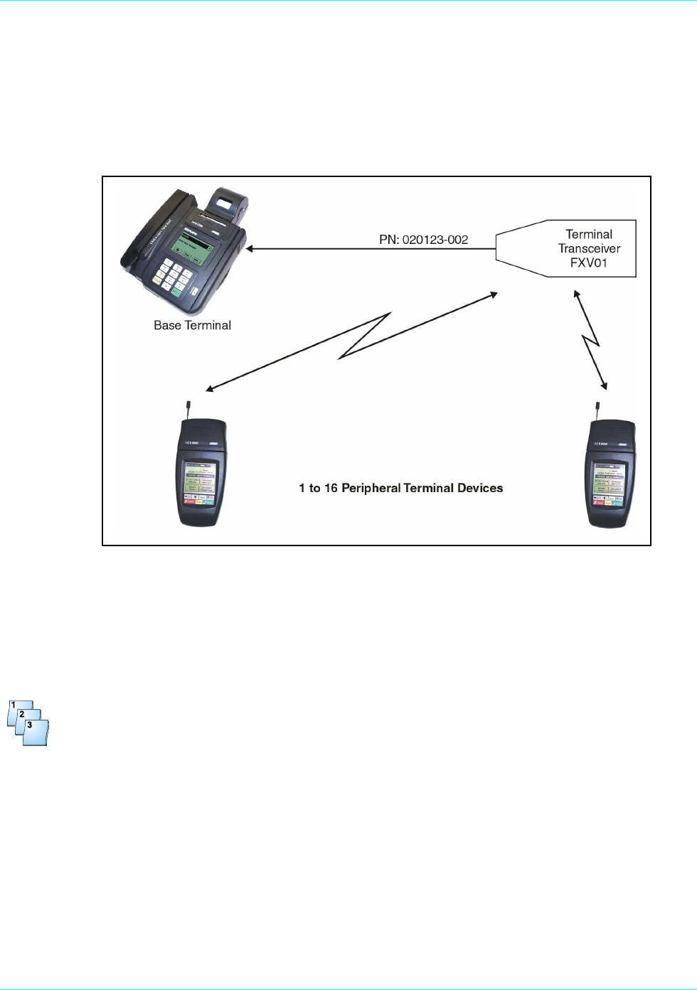
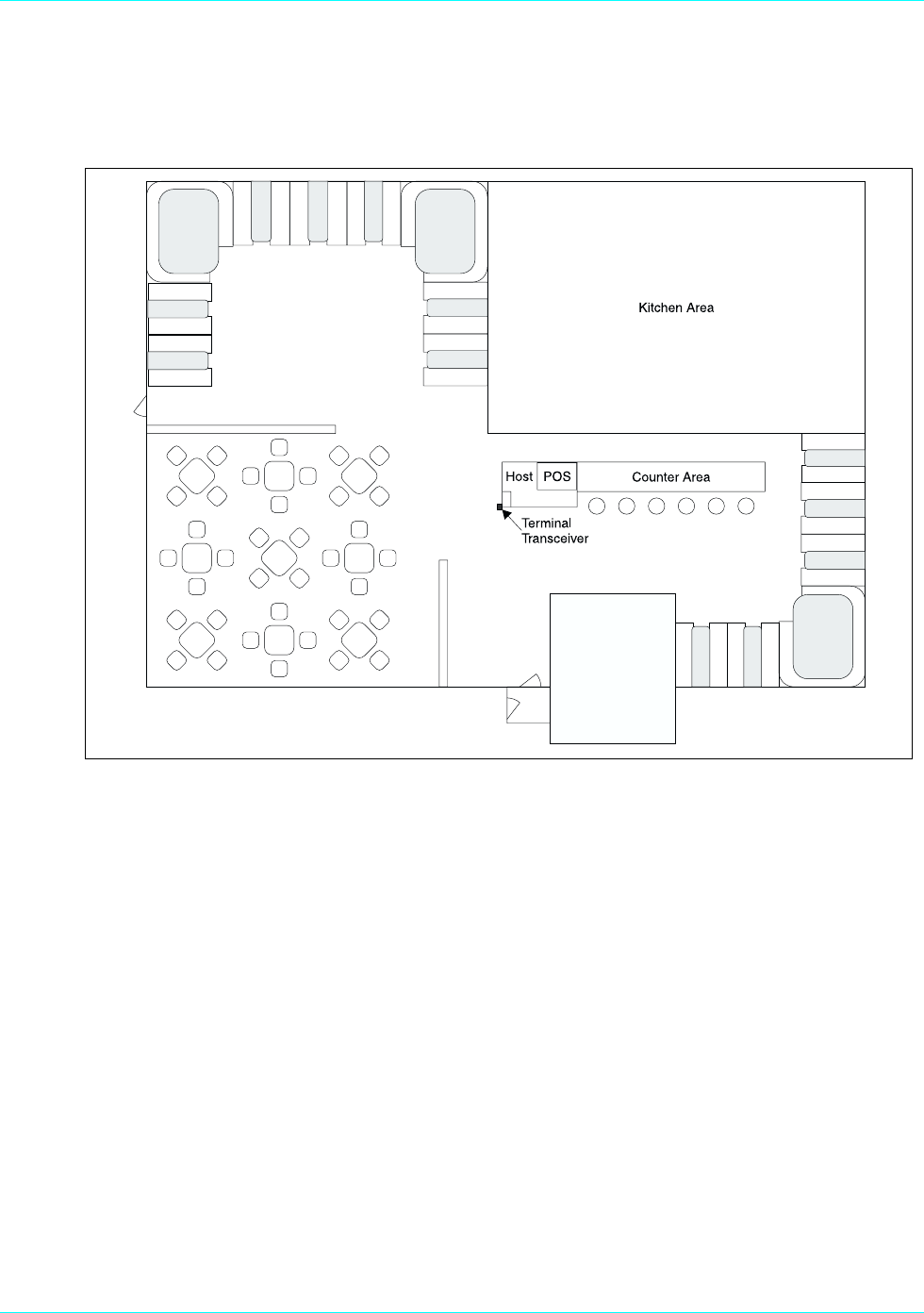
Basic System
Figure 4-1 shows the basic ICE configuration. The terminal transceiver should be less than 100 feet
from the peripheral terminal device. This short range reduces the possibility of interference with other
communication systems using the same radio spectrum. Causing such interference is a violation of
FCC regulations.
Figure 4-1. Basic configuration
Basic System Installation
Use the following procedure to install the basic system wireless hardware.
Step-by-Step
To install the basic system:
1. Ensure the host terminal is properly configured and connected for use as a standard POS
terminal.
See the manual provided with the host POS terminal.
2. Mount the terminal transceiver, Hypercom P/N 020123-002, to a vertical surface. Place it as high
as possible in an area that has the best visibility from the area where the peripheral terminal
devices are used. You may mount the transceiver by using the metal hook or the rubber suction
cups provided. An alternate method is to remove the metal hook and the rubber suction cups,
replacing them with double-sided tape. The terminal transceiver must not be mounted on or next
to metal objects.
Chapter 4
4-4 ICE 5700 Hardware and Installation Operators Manual 940310-001, rev. A
3. Insert the male connector on the 12-foot cable from the terminal transceiver into the female
connector on the single-unit adapter cable.
If the 12-foot cable is not long enough, it may be extended up to 100 feet by using any
six-conductor, one-to-one standard telephone extender cable available at various electronic
appliance retail outlets. The cable may be extended up to 1000 feet by substituting a terminal
transceiver interface for the single unit adapter cable.
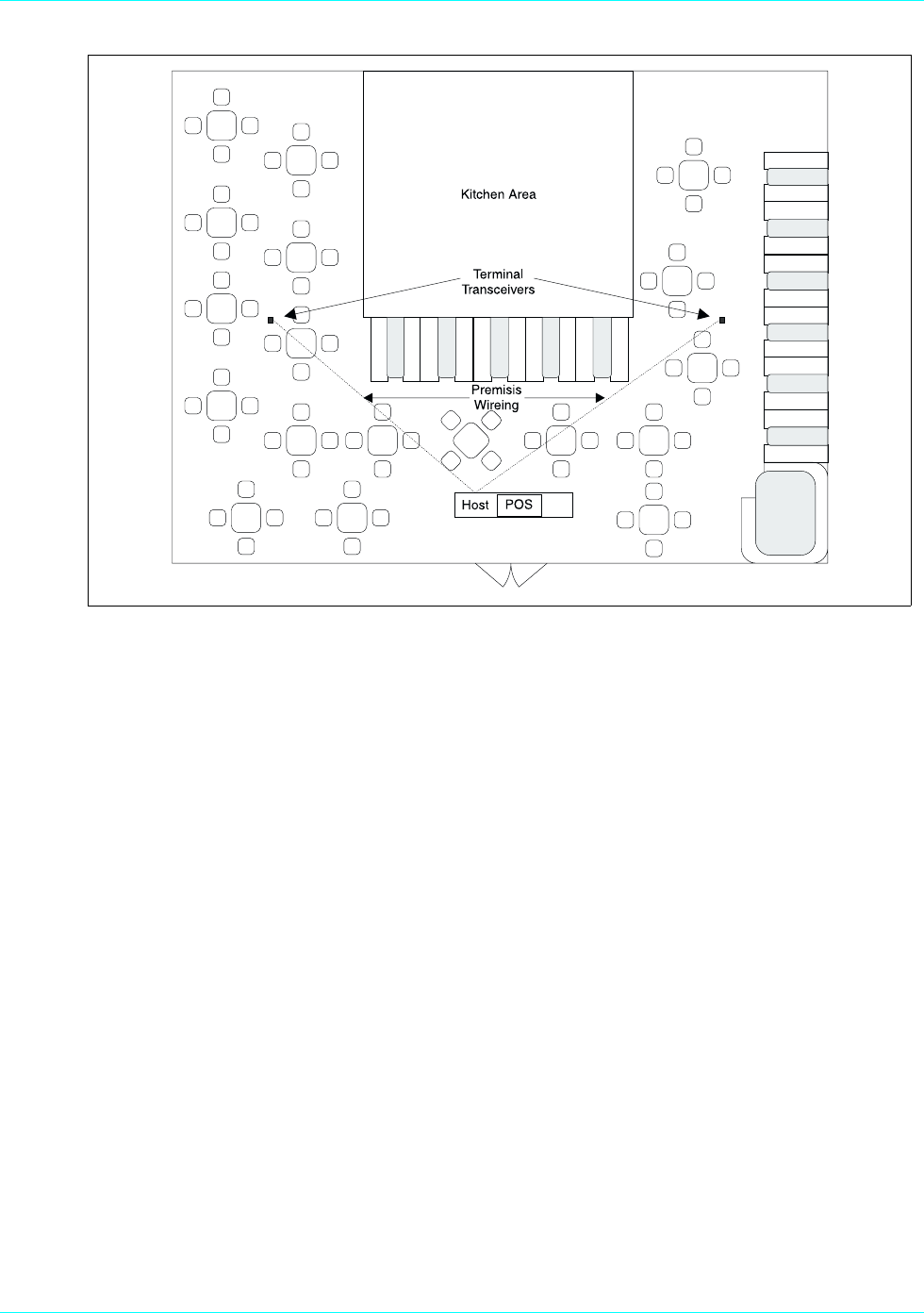
Extending Basic Coverage Area
If the basic system does not cover enough space or major gaps exist in the coverage, you can extend
the area covered. The example in Figure 4-2 shows how to extend coverage or fill in gaps by adding a
terminal transceiver interface and an additional terminal transceiver.
Figure 4-2. Extending basic coverage
WARNING
To avoid damaging the terminal transceiver unit, do not insert the cable connectors from the single unit
adapter or the terminal transceiver into any receptacle designated for use with the premises telephone
system.

Wireless POS Terminal Interface
940310-001, rev. A Hypercom Corporation 4-5
Installing Extended Basic Coverage Area
Use this procedure for installing the extended basic coverage wireless hardware.
Step-by-Step
To install the extended basic coverage area:
1. Ensure the host terminal is properly configured and connected for use as a standard POS
terminal.
See the manual provided with the host POS terminal.
2. If this is a system upgrade from the basic system, discard the single unit adapter cable. Insert one
end of the PIN pad cable, Hypercom P/N 810022-001, into the PIN pad port of the host POS
terminal. Insert the other end of the PIN pad cable into the connector marked To Terminal on the
terminal transceiver interface.
3. Mount the two terminal transceivers, Hypercom P/N 020123-002, to a vertical surface. Place them
as high as possible in an area that has the best visibility from the areas where the peripheral
devices are used. Separate the transceivers as far as possible from each other while still providing
the required coverage. You may mount the transceivers by using the metal hook or the rubber
suction cups provided. An alternate method is to remove the metal hook and the rubber suction
cups, replacing them with double-sided tape. The terminal transceivers must not be mounted on
or next to metal objects.
4. Insert the male connector of the 12-foot cable from the terminal transceivers into the female
connectors marked Terminal Transceiver 1 or Terminal Transceiver 2 on the terminal transceiver
interface.
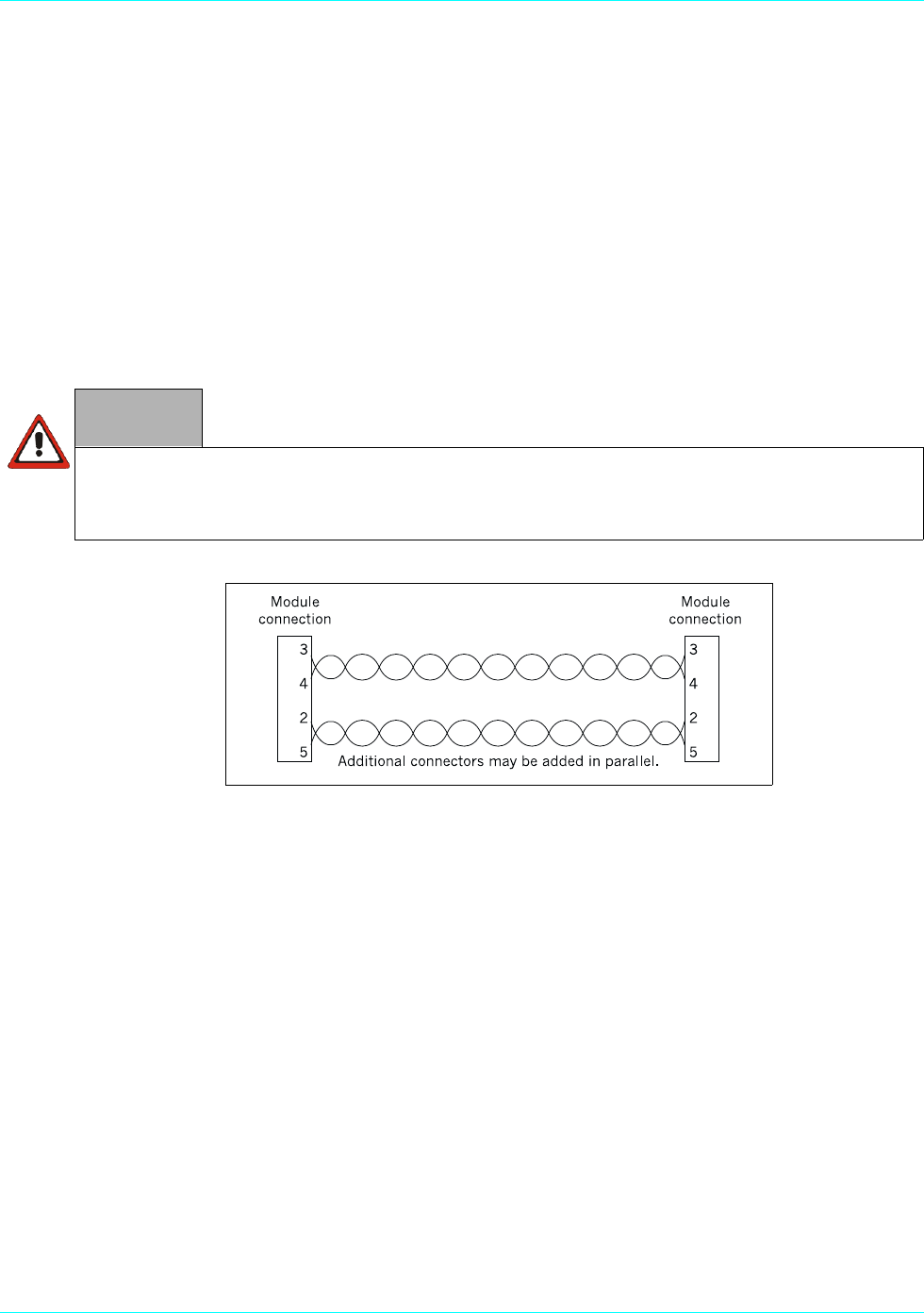
If the 12-foot cable is not long enough, it may be extended up to 1000 feet by using any four-
conductor, one-to-one standard telephone extender cable available at various electronic appliance
retail outlets.
You can also have the premises wired for extending the cables. Firms that install telephone cabling
in buildings can perform this task because the wiring is identical to a two-circuit telephone system.
WARNING
To avoid damaging the terminal transceiver unit, do not insert the cable connectors from the single unit
adapter or the terminal transceiver into any receptacle designated for use with the premises telephone
system.
Chapter 4
4-6 ICE 5700 Hardware and Installation Operators Manual 940310-001, rev. A
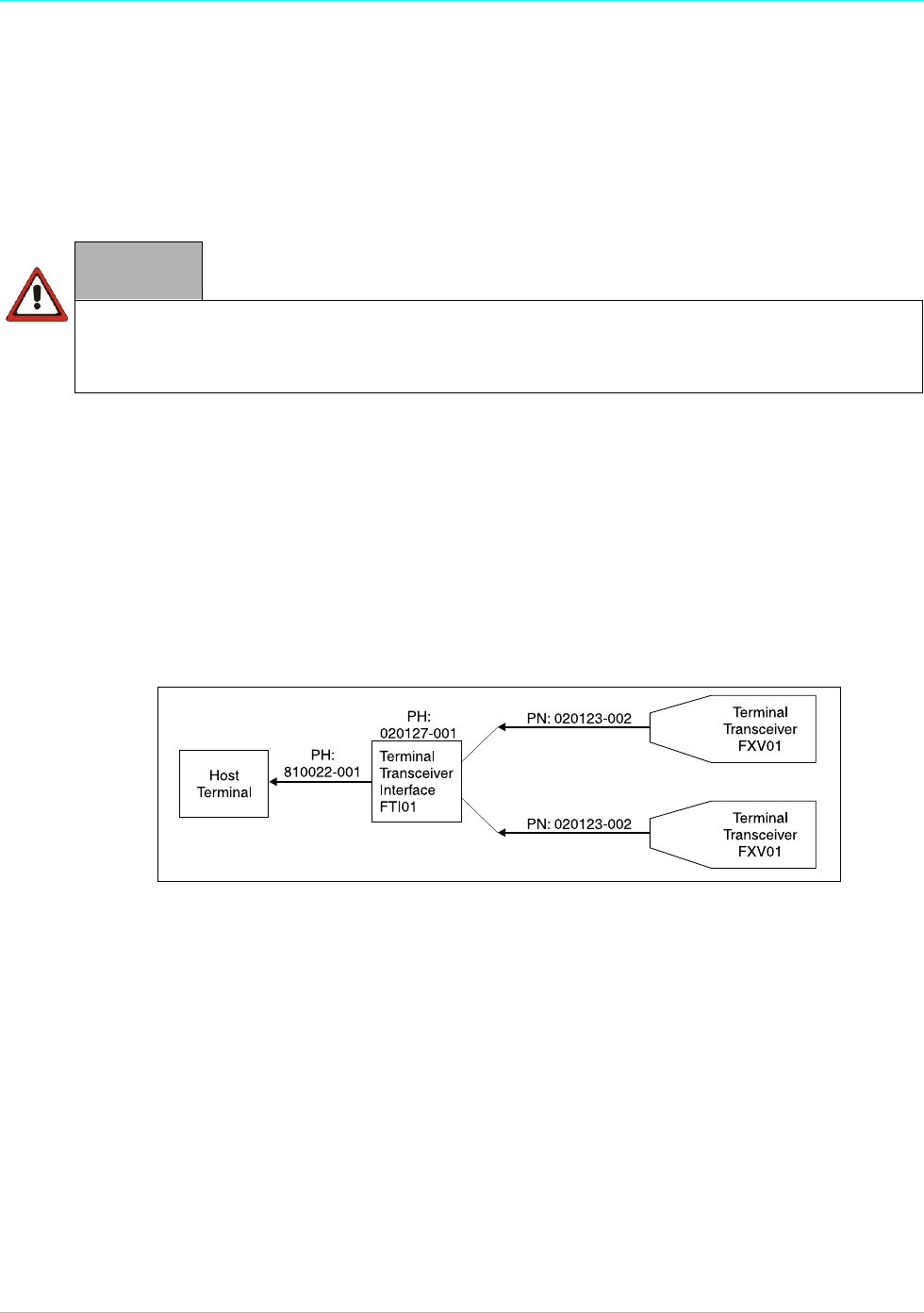
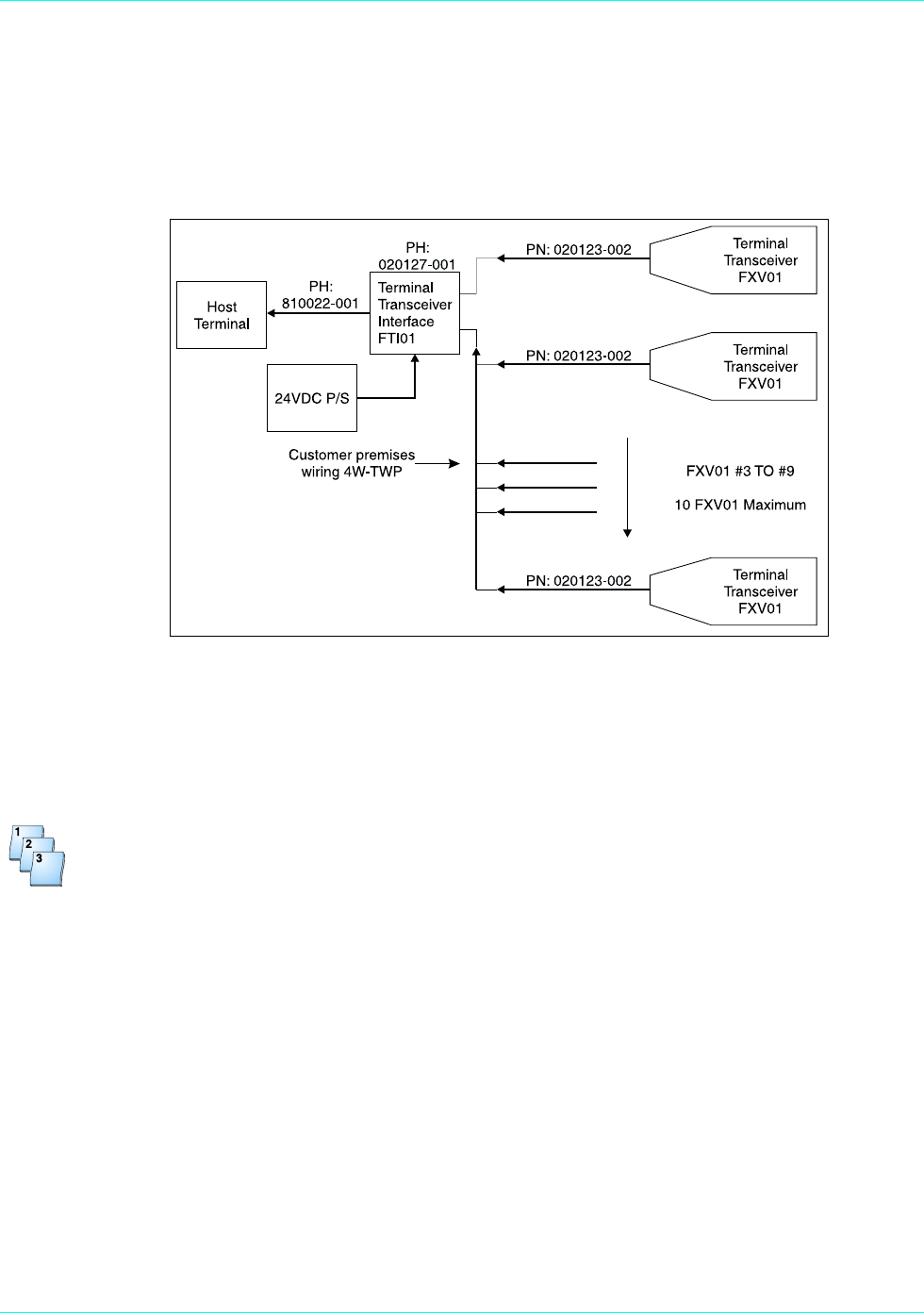
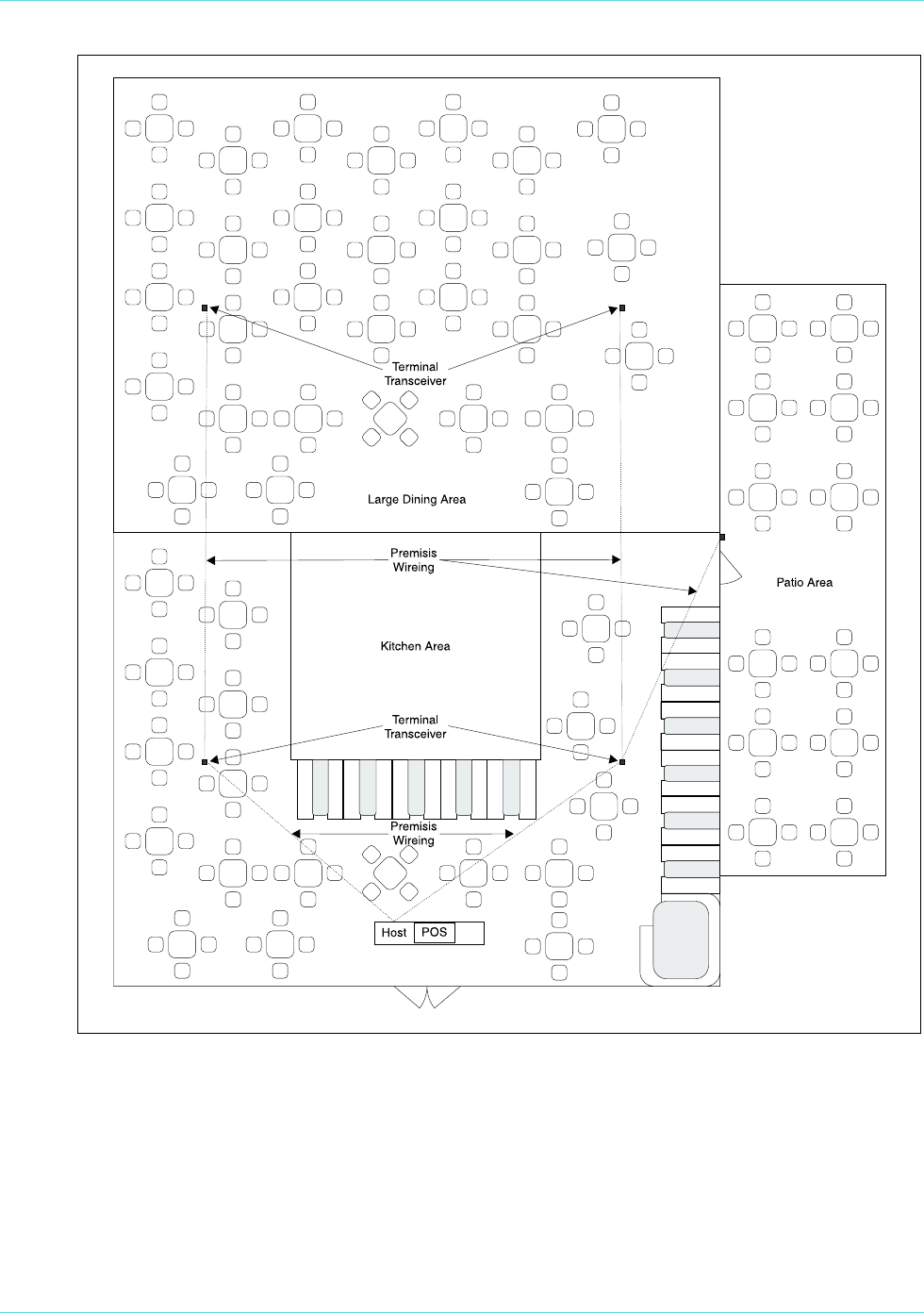
Large-Area Coverage
If the area to be serviced is too large for the extended basic coverage, configure the system for large-
area coverage. (See Figure 4-3.) Add a power supply, Hypercom P/N 870003-001, to the terminal
transceiver interface. The premises wiring may be expanded to support an additional eight terminal
transceivers for a total of ten, maximizing the system for large areas or to fill in gaps in coverage.
Figure 4-3. Large area coverage
Installing Large Area Coverage
Step-by-Step
To install large area coverage:
1. Ensure the host terminal is properly configured and connected for use as a standard POS
terminal.
See the manual provided with the host POS terminal.
2. Insert one end of the PIN pad cable, Hypercom P/N 810022-001, into the PIN pad port of the host
POS terminal. Insert the other end of the PIN pad cable into the connector marked To Ter mi nal on
the terminal transceiver interface, Hypercom P/N 020192-001.
3. Mount the terminal transceivers, Hypercom P/N 020123-002, to a vertical surface. Place them as
high as possible in an area that has the best visibility from the areas where the peripheral terminal
devices are used. Separate the transceivers as far as possible from each other while still providing
the required coverage. You may mount the transceivers by using the metal hook or the rubber
suction cups provided. An alternate method is to remove the metal hook and the rubber suction
cups, replacing them with double-sided tape. The terminal transceivers must not be mounted on
or next to metal objects.
Wireless POS Terminal Interface
940310-001, rev. A Hypercom Corporation 4-7
4. Insert the 24-Volt power cable from the power supply, Hypercom P/N 870003-001, into the terminal
transceiver interface receptacle marked Power. Insert the AC power cable from the power supply
into an appropriate AC receptacle.
5. Insert the male connector of the 12-foot cable from the terminal transceivers into the female
connectors marked Terminal Transceiver 1 or Terminal Transceiver 2 on the terminal transceiver
interface.
If the 12-foot cable is not long enough, it may be extended up to 1000 feet by using any four
conductor, one-to-one standard telephone extender cable available at various electronic appliance
retail outlets.
You can also have the premises wired for extending the cables. Firms that install telephone cabling
in buildings can perform this task because the wiring is identical to a two-circuit telephone system.
Figure 4-4. Premises wiring diagram
WARNING
To avoid damaging the terminal transceiver unit, do not insert the cable connectors from the single unit
adapter or the terminal transceiver into any receptacle designated for use with the premises telephone
system.
Chapter 4
4-8 ICE 5700 Hardware and Installation Operators Manual 940310-001, rev. A
Installation Examples
Figures 4-5 through 4-7 are installation examples.
Figure 4-5. Basic system example
Wireless POS Terminal Interface
940310-001, rev. A Hypercom Corporation 4-9
Figure 4-6. Extended basic example
Chapter 4
4-10 ICE 5700 Hardware and Installation Operators Manual 940310-001, rev. A
Figure 4-7. Large area example

Index
940310-001, rev. A Hypercom Corporation I-1
Index
Numerics
24-Vollt power cable . . . . . . . . . . . . . . . . . . . . . . . . . . . . 4-7
A
AC
adaptor . . . . . . . . . . . . . . . . . . . . . . . . . . . . . . . . . . 2-1
power cable . . . . . . . . . . . . . . . . . . . . . . . . . . . 2-1, 4-7
Adaptor cable . . . . . . . . . . . . . . . . . . . . . . . . . . . . . . . . . . 4-1
Authorized Service . . . . . . . . . . . . . . . . . . . . . . . . . . . . . . 1-2
auto receipt cutter . . . . . . . . . . . . . . . . . . . . . . . . . . . . . . 1-5
C
Caution . . . . . . . . . . . . . . . . . . . . . . . . . . . . . . . . . . . . . . . xv
messages . . . . . . . . . . . . . . . . . . . . . . . . . . . . . . . . . xv
Class A . . . . . . . . . . . . . . . . . . . . . . . . . . . . . . . . . . . . . . . iv
Class B . . . . . . . . . . . . . . . . . . . . . . . . . . . . . . . . . . . . . . 4-2
commission decision . . . . . . . . . . . . . . . . . . . . . . . . . . . . 1-2
conventions . . . . . . . . . . . . . . . . . . . . . . . . . . . . . . . . . . . .xiv
co-processor . . . . . . . . . . . . . . . . . . . . . . . . . . . . . . . . . . 1-3
CTR21 . . . . . . . . . . . . . . . . . . . . . . . . . . . . . . . . . . . . . . . . iv
D
data encryption . . . . . . . . . . . . . . . . . . . . . . . . . . . . . . . . 4-1
diagnosis . . . . . . . . . . . . . . . . . . . . . . . . . . . . . . . . . . . . . 2-4
dimensions . . . . . . . . . . . . . . . . . . . . . . . . . . . . . . . . . . . . 1-6
E
electrical Safety . . . . . . . . . . . . . . . . . . . . . . . . . . . . . . . . 1-2
electromagnetic . . . . . . . . . . . . . . . . . . . . . . . . . . . . . . . . 1-2
encryption key storage . . . . . . . . . . . . . . . . . . . . . . . . . . . 1-3
F
FastPOS . . . . . . . . . . . . . . . . . . . . . . . . . . . . . . . . . . . . . 1-5
FCC Rules
Class A . . . . . . . . . . . . . . . . . . . . . . . . . . . . . . . . . . . iv
Class B . . . . . . . . . . . . . . . . . . . . . . . . . . . . . . . . . . 4-2
CTR21 . . . . . . . . . . . . . . . . . . . . . . . . . . . . . . . . . . . . iv
Part 15 . . . . . . . . . . . . . . . . . . . . . . . . . . . . . . . . . . . . iv
Part 68 . . . . . . . . . . . . . . . . . . . . . . . . . . . . . . . . . . . . iv
FTI01 . . . . . . . . . . . . . . . . . . . . . . . . . . . . . . . . . . . . . . . . 4-1
function blocks . . . . . . . . . . . . . . . . . . . . . . . . . . . . . . . . . 4-1
G
guide
audience . . . . . . . . . . . . . . . . . . . . . . . . . . . . . . . . . .xiii
conventions . . . . . . . . . . . . . . . . . . . . . . . . . . . . . . . .xiv
organization . . . . . . . . . . . . . . . . . . . . . . . . . . . . . . . .xiii
I
ICE 5700
auto receipt cutter . . . . . . . . . . . . . . . . . . . . . . . . . . 1-5
dimensions . . . . . . . . . . . . . . . . . . . . . . . . . . . . . . . 1-6
keyboard . . . . . . . . . . . . . . . . . . . . . . . . . . . . . . . . . 1-3
magnetic swipe card reader . . . . . . . . . . . . . . . . . . 1-4
memory . . . . . . . . . . . . . . . . . . . . . . . . . . . . . . . . . . 1-5
modem . . . . . . . . . . . . . . . . . . . . . . . . . . . . . . . . . . 1-5
PIN pad . . . . . . . . . . . . . . . . . . . . . . . . . . . . . . . . . . 1-3
power
requirements . . . . . . . . . . . . . . . . . . . . . . . . . . 1-5
security . . . . . . . . . . . . . . . . . . . . . . . . . . . . . . . . . . 1-3
thermal printer . . . . . . . . . . . . . . . . . . . . . . . . . . . . . 1-5
touch-screen display . . . . . . . . . . . . . . . . . . . . . . . . 1-4
initialization . . . . . . . . . . . . . . . . . . . . . . . . . . . . . . . . . . . 3-4
installation
connecting the telephone line . . . . . . . . . . . . . . . . . 2-3
power up . . . . . . . . . . . . . . . . . . . . . . . . . . . . . . . . . 2-1
self-test and diagnostics . . . . . . . . . . . . . . . . . . . . . 2-4
interference . . . . . . . . . . . . . . . . . . . . . . . . . . . . . . . . . . . 4-3
K
keyboard . . . . . . . . . . . . . . . . . . . . . . . . . . . . . . . . . . . . . 1-3
L
load program . . . . . . . . . . . . . . . . . . . . . . . . . . . . . . . . . . 3-3
M
MAC software . . . . . . . . . . . . . . . . . . . . . . . . . . . . . . . . . 3-3
MAC-ing . . . . . . . . . . . . . . . . . . . . . . . . . . . . . . . . . . . . . . 1-3
magnetic swipe card reader . . . . . . . . . . . . . . . . . . . . . . 1-4
memory . . . . . . . . . . . . . . . . . . . . . . . . . . . . . . . . . . . . . . 1-5
page . . . . . . . . . . . . . . . . . . . . . . . . . . . . . . . . . . . . 2-4
message authentication . . . . . . . . . . . . . . . . . . . . . . . . . . 1-3
modem . . . . . . . . . . . . . . . . . . . . . . . . . . . . . . . . . . . . . . . 1-5
O
one-to-one standard phone cable . . . . . . . . . . . . . . . . . . 4-5
P
Part 15 . . . . . . . . . . . . . . . . . . . . . . . . . . . . . . . . . . . . . . . 4-2
Part 68 . . . . . . . . . . . . . . . . . . . . . . . . . . . . . . . . . . . . . . . . .iv
peripheral terminal device . . . . . . . . . . . . . . . . . . . . 4-1, 4-3
PIN pad . . . . . . . . . . . . . . . . . . . . . . . . . . . . . . . . . . . xiii, 1-3
cable . . . . . . . . . . . . . . . . . . . . . . . . . . . . . . . . . . . . 4-5
encryption . . . . . . . . . . . . . . . . . . . . . . . . . . . . . . . . 1-3
pixels . . . . . . . . . . . . . . . . . . . . . . . . . . . . . . . . . . . . . . . . 1-4
power requirements . . . . . . . . . . . . . . . . . . . . . . . . . . . . . 1-5
PSTN . . . . . . . . . . . . . . . . . . . . . . . . . . . . . . . . . . . . . . . . 1-2
R
RAM . . . . . . . . . . . . . . . . . . . . . . . . . . . . . . . . . . . . . . . . . 1-3
receiver . . . . . . . . . . . . . . . . . . . . . . . . . . . . . . . . . . . . . . 4-2
REN . . . . . . . . . . . . . . . . . . . . . . . . . . . . . . . . . . . . . . . . iv, v

Index
I-2 ICE 5700 Hardware and Installation Operators Manual 940310-001, rev. A
S
SAM
smart card . . . . . . . . . . . . . . . . . . . . . . . . . . . . . . . . 1-3
security . . . . . . . . . . . . . . . . . . . . . . . . . . . . . . . . . . . . . . 1-3
self-diagnostic . . . . . . . . . . . . . . . . . . . . . . . . . . . . . . . . . 2-4
setup procedures
ICE 5700
loading printer paper . . . . . . . . . . . . . . . . . . . . 3-5
initialization . . . . . . . . . . . . . . . . . . . . . . . . . . . . . . . 3-4
load program . . . . . . . . . . . . . . . . . . . . . . . . . . . . . . 3-3
wireless . . . . . . . . . . . . . . . . . . . . . . . . . . . . . . . . . . 4-3
short range . . . . . . . . . . . . . . . . . . . . . . . . . . . . . . . . . . . 4-3
T
Terminal Transceiver
FTI01 . . . . . . . . . . . . . . . . . . . . . . . . . . . . . . . . . . . . 4-1
Interface . . . . . . . . . . . . . . . . . . . . . . . . . . . . . . . . . 4-1
Term-Master . . . . . . . . . . . . . . . . . . . . . . . . . . . . . . . . . . 3-1
thermal printer . . . . . . . . . . . . . . . . . . . . . . . . . . . . . . . . . 1-5
touch-screen . . . . . . . . . . . . . . . . . . . . . . . . . . . . . . . . . . 1-4
display . . . . . . . . . . . . . . . . . . . . . . . . . . . . . . . . . . . 1-4
W
Warning . . . . . . . . . . . . . . . . . . . . . . . . . . . . . . . . . . . . . . . xv
messages . . . . . . . . . . . . . . . . . . . . . . . . . . . . . . . . . xv
Wireless POS Terminal interface
function blocks . . . . . . . . . . . . . . . . . . . . . . . . . . . . . 4-1
operations . . . . . . . . . . . . . . . . . . . . . . . . . . . . . . . . 4-2
instructions . . . . . . . . . . . . . . . . . . . . . . . . . . . 4-2

We Welcome Your Comments
Please fax this page with your comments to Hypercom Corporation at 602.504.4990.
Document Number: 940310-001, rev A
1. In one word, how would you describe this guide? _____________________________________
2. How do you use this guide?
I read it from beginning to end.
I read only the sections that relate to my immediate needs.
I read only the sections that relate to my job.
3. Where do you usually look first to find information in this guide?
Table of contents
Index
Search through the pages until I find what I am looking for
4. How easily can you find information in this guide?
1 (Not easily) 23 4 5 (Very easily)
5. How clear is the information in this guide?
1 (Not clear) 23 4 5 (Very clear)
6. How easily can you follow the instructions described in this guide?
1 (Not easily) 23 4 5 (Very easily)
7. How well did you understand the product before reading this guide?
1 (Not well) 23 4 5 (Very well)
8. How well do you understand the product after reading this guide?
1 (Not well) 23 4 5 (Very well)
9. The best aspect of this guide is ___________________________________________________ .
10.The least useful aspect of this guide is ______________________________________________ .
Additional comments:

Document Number 940310-001, rev A
Printed in the USA
