Hytera Communications DS-6211U1C4 Lite Digital Trunking Base Station User Manual DS 6211 Base Station
Hytera Communications Corporation Ltd. Lite Digital Trunking Base Station DS 6211 Base Station
Users Manual
DS-6211 Base Station
User Guide
Document Version: V00
Release Date: 03-2013
Copyright Information
Hytera is the trademark or registered trademark of Hytera Communications Co., Ltd. (the Company) in
PRC and/or other countries or areas. The Company retains the ownership of its trademarks and product
names. All other trademarks and/or product names that may be used in this manual are properties of
their respective owners.
The product described in this manual may include the Company’s computer programs stored in memory
or other media. Laws in PRC and/or other countries or areas protect the exclusive rights of the Company
with respect to its computer programs. The purchase of this product shall not be deemed to grant, either
directly or by implication, any rights to the purchaser regarding the Company’s computer programs. Any
of the Company’s computer programs may not be copied, modified, distributed, decompiled, or
reverse-engineered in any manner without the prior written consent of the Company.
Disclaimer
The Company endeavors to achieve the accuracy and completeness of this manual, but no warranty of
accuracy or reliability is given. All the specifications and designs are subject to change without notice
due to continuous technology development. No part of this manual may be copied, modified, translated,
or distributed in any manner without the express written permission of us.
We do not guarantee, for any particular purpose, the accuracy, validity, timeliness, legitimacy or
completeness of the Third Party products and contents involved in this manual.
If you have any suggestions or would like to learn more details, please visit our website at:
http://www.hytera.com.

User Guide Contents
i
Contents
Documentation Information ................................................................................................................... 1
1. Checking Items in the Package ......................................................................................................... 2
2. Hardware Description ........................................................................................................................ 3
2.1 PDU ................................................................................................................................................ 3
2.1.1 Specifications ........................................................................................................................ 3
2.1.2 Rear Panel ............................................................................................................................ 4
2.2 CHU ................................................................................................................................................ 4
2.2.1 Introduction ........................................................................................................................... 4
2.2.2 Specifications ........................................................................................................................ 5
2.2.3 Front Panel ........................................................................................................................... 9
2.2.4 LED Indicator ........................................................................................................................ 9
2.2.5 Rear Panel .......................................................................................................................... 10
2.3 CHU Power Supply ....................................................................................................................... 11
2.3.1 Introduction ......................................................................................................................... 11
2.3.2 Specifications ...................................................................................................................... 11
2.3.3 Front Panel ......................................................................................................................... 12
2.3.4 Rear Panel .......................................................................................................................... 13
2.4 Switch ........................................................................................................................................... 14
2.4.1 Introduction ......................................................................................................................... 14
2.4.2 Specifications ...................................................................................................................... 14
2.4.3 Front Panel ......................................................................................................................... 14
2.4.4 LED Indicator ...................................................................................................................... 15
2.4.5 Rear Panel .......................................................................................................................... 15
2.5 Router ........................................................................................................................................... 16
2.5.1 Introduction ......................................................................................................................... 16
2.5.2 Specifications ...................................................................................................................... 16
2.5.3 Front Panel ......................................................................................................................... 16
2.5.4 LED Indicator ...................................................................................................................... 17
2.5.5 Rear Panel .......................................................................................................................... 17
2.6 Server ........................................................................................................................................... 18
2.6.1 Introduction ......................................................................................................................... 18
2.6.2 Specifications ...................................................................................................................... 18
2.6.3 Front Panel ......................................................................................................................... 19
2.6.4 Rear Panel .......................................................................................................................... 19
2.7 PSU .............................................................................................................................................. 20
2.7.1 Introduction ......................................................................................................................... 20
2.7.2 Specifications ...................................................................................................................... 20

Contents User Guide
ii
2.7.3 Front Panel ......................................................................................................................... 21
2.7.4 Rear Panel .......................................................................................................................... 22
2.8 DIU ................................................................................................................................................ 22
2.8.1 Introduction ......................................................................................................................... 22
2.8.2 Specifications ...................................................................................................................... 22
2.8.3 Front Panel ......................................................................................................................... 23
2.8.4 Rear Panel .......................................................................................................................... 23
2.9 DPU .............................................................................................................................................. 24
2.9.1 Introduction ......................................................................................................................... 24
2.9.2 Specifications ...................................................................................................................... 24
2.9.3 Front Panel ......................................................................................................................... 25
2.9.4 Rear Panel .......................................................................................................................... 25
2.10 COM ........................................................................................................................................... 26
2.10.1 Introduction ....................................................................................................................... 26
2.10.2 Specifications .................................................................................................................... 26
2.10.3 Rear Panel ........................................................................................................................ 27
3. Hardware Installation ....................................................................................................................... 29
3.1 Safety Information ......................................................................................................................... 29
3.1.1 Electrical Safety .................................................................................................................. 29
3.1.2 Working Aloft ....................................................................................................................... 29
3.2 Installation Preparation ................................................................................................................. 30
3.2.1 Technical Files .................................................................................................................... 30
3.2.2 Personnel ........................................................................................................................... 30
3.2.3 Instruments and Tools ......................................................................................................... 30
3.2.4 Unpacking the Base Station ................................................................................................ 31
3.3 Installation Location for the Internal Unit ....................................................................................... 34
3.4 Installation Flow ............................................................................................................................ 34
3.5 Wiring Diagram ............................................................................................................................. 35
3.6 Installing the Cabinet .................................................................................................................... 39
3.6.1 Determining a Location for the Cabinet .............................................................................. 39
3.6.2 Fixing the Cabinet ............................................................................................................... 39
3.6.3 Testing the Insulation Performance ..................................................................................... 39
3.7 Installing the Internal Units ............................................................................................................ 40
3.7.1 Opening the Front Door and Back Door ............................................................................. 40
3.7.2 Removing the Side Door ..................................................................................................... 40
3.7.3 Installing the Internal Units .................................................................................................. 41
3.7.4 Connecting the Internal Cables ........................................................................................... 43
3.7.5 Installing the Decorative Unit .............................................................................................. 44
3.7.6 Installing the Side Door ....................................................................................................... 44

User Guide Contents
iii
3.8 Connecting the External Cables ................................................................................................... 45
3.8.1 Requirements ..................................................................................................................... 45
3.8.2 Cables to Be Connected ..................................................................................................... 45
3.9 Performing Post-installation Check ............................................................................................... 45
3.9.1 Requirements ..................................................................................................................... 45
3.9.2 Checking the Cabinet ......................................................................................................... 45
3.9.3 Checking the Cable ............................................................................................................ 46
3.9.4 Checking the Power Supply Condition ................................................................................ 47
3.9.5 Checking the Environment .................................................................................................. 47
4. Basic Operations .............................................................................................................................. 49
4.1 Powering up the Base Station ....................................................................................................... 49
4.2 Powering off the Base Station ....................................................................................................... 49
5. Routine Maintenance ....................................................................................................................... 50
5.1 Purpose ........................................................................................................................................ 50
5.2 Tasks ............................................................................................................................................ 50
A Abbreviations .................................................................................................................................... 51

Figures User Guide
iv
Figures
Figure 2-1 Rear Panel of PDU .................................................................................................................. 4
Figure 2-2 Logical Architecture of CHU .................................................................................................... 4
Figure 2-3 Front Panel of CHU ................................................................................................................. 9
Figure 2-4 Rear Panel of CHU ............................................................................................................... 11
Figure 2-5 Front Panel of CHU Power Supply ........................................................................................ 13
Figure 2-6 Rear Panel of CHU Power Supply ........................................................................................ 13
Figure 2-7 Front Panel of Switch ............................................................................................................ 14
Figure 2-8 Rear Panel of Switch ............................................................................................................. 15
Figure 2-9 Front Panel of Router ............................................................................................................ 16
Figure 2-10 Rear Panel of Router .......................................................................................................... 18
Figure 2-11 Front Panel of Server .......................................................................................................... 19
Figure 2-12 Rear Panel of Server ........................................................................................................... 20
Figure 2-13 Front Panel of PSU ............................................................................................................. 22
Figure 2-14 Rear Panel of PSU .............................................................................................................. 22
Figure 2-15 Front Panel of DIU .............................................................................................................. 23
Figure 2-16 Rear Panel of DIU ............................................................................................................... 24
Figure 2-17 Front Panel of DPU ............................................................................................................. 25
Figure 2-18 Rear Panel of DPU .............................................................................................................. 26
Figure 2-19 Rear Panel of COM ............................................................................................................. 28
Figure 3-1 Laying the Wooden Case ...................................................................................................... 32
Figure 3-2 Pulling the Tongue Piece Straight .......................................................................................... 32
Figure 3-3 Removing the Wooden Cover and Side Wooden Plate ......................................................... 32
Figure 3-4 Unpacking the Carton ........................................................................................................... 33
Figure 3-5 Installation Locations for Internal Units of 4-Carrier Base Station ......................................... 34
Figure 3-6 Installation Flow .................................................................................................................... 35
Figure 3-7 Wiring Diagram for 4-carrier Base Station ............................................................................. 38
Figure 3-8 Installation Location for Base Station .................................................................................... 39
Figure 3-9 Fixing the Bolt ....................................................................................................................... 39
Figure 3-10 Opening the Front Door and Back Door .............................................................................. 40
Figure 3-11 Removing the Side Door ..................................................................................................... 41
Figure 3-12 Installing the Tray ................................................................................................................ 42
Figure 3-13 Installing the CHU ............................................................................................................... 42
Figure 3-14 Installing the Router ............................................................................................................ 43
Figure 3-15 Installing the COM ............................................................................................................... 43
Figure 3-16 Outline of Cable .................................................................................................................. 44
Figure 3-17 Installing the Decorative Unit ............................................................................................... 44

User Guide Tables
v
Tables
Table 1-1 Configuration of 4-carrier Base Station ..................................................................................... 2
Table 2-1 PDU Specifications ................................................................................................................... 4
Table 2-2 Descriptions on Rear Panel of PDU .......................................................................................... 4
Table 2-3 CHU Specifications ................................................................................................................... 9
Table 2-4 Descriptions on Front Panel of CHU ......................................................................................... 9
Table 2-5 Descriptions on CHU Indicators .............................................................................................. 10
Table 2-6 Descriptions on Rear Panel of CHU ....................................................................................... 11
Table 2-7 CHU Power Supply Specifications .......................................................................................... 12
Table 2-8 Descriptions on Front Panel of CHU Power Supply ................................................................ 13
Table 2-9 Descriptions on Rear Panel of CHU Power Supply ................................................................ 13
Table 2-10 Switch Specifications ............................................................................................................ 14
Table 2-11 Descriptions on Front Panel of Switch .................................................................................. 15
Table 2-12 Descriptions on Switch Indicators ......................................................................................... 15
Table 2-13 Descriptions on Rear Panel of Switch ................................................................................... 15
Table 2-14 Router Specifications ............................................................................................................ 16
Table 2-15 Descriptions on Front Panel of Router .................................................................................. 17
Table 2-16 Descriptions on Router Indicators ......................................................................................... 17
Table 2-17 Descriptions on Rear Panel of Router .................................................................................. 18
Table 2-18 Server Specifications ............................................................................................................ 19
Table 2-19 Descriptions on Front Panel of Server .................................................................................. 19
Table 2-20 Descriptions on Rear Panel of Server ................................................................................... 20
Table 2-21 PSU Specifications ............................................................................................................... 21
Table 2-22 Descriptions on Rear Panel of PSU ...................................................................................... 22
Table 2-23 DIU Specifications ................................................................................................................. 23
Table 2-24 Descriptions on Rear Panel of DIU ....................................................................................... 24
Table 2-25 DPU Specifications ............................................................................................................... 25
Table 2-26 Descriptions on Rear Panel of DPU ...................................................................................... 26
Table 2-27 COM Specifications .............................................................................................................. 27
Table 2-28 Descriptions on Rear Panel of COM ..................................................................................... 28
Table 3-1 Technical Files ........................................................................................................................ 30
Table 3-2 Instruments and Tools ............................................................................................................. 31
Table 3-3 Cables to Be Connected ......................................................................................................... 45
Table 3-4 Checklist for the Cabinet ......................................................................................................... 46
Table 3-5 Checklist for the Cable ............................................................................................................ 46
Table 3-6 Checklist for Power Supply Condition ..................................................................................... 47
Table 3-7 Checklist for Environment ....................................................................................................... 48
User Guide Documentation Information
1
Documentation Information
This section describes the conventions and revision history of this document.
Documentation Conventions
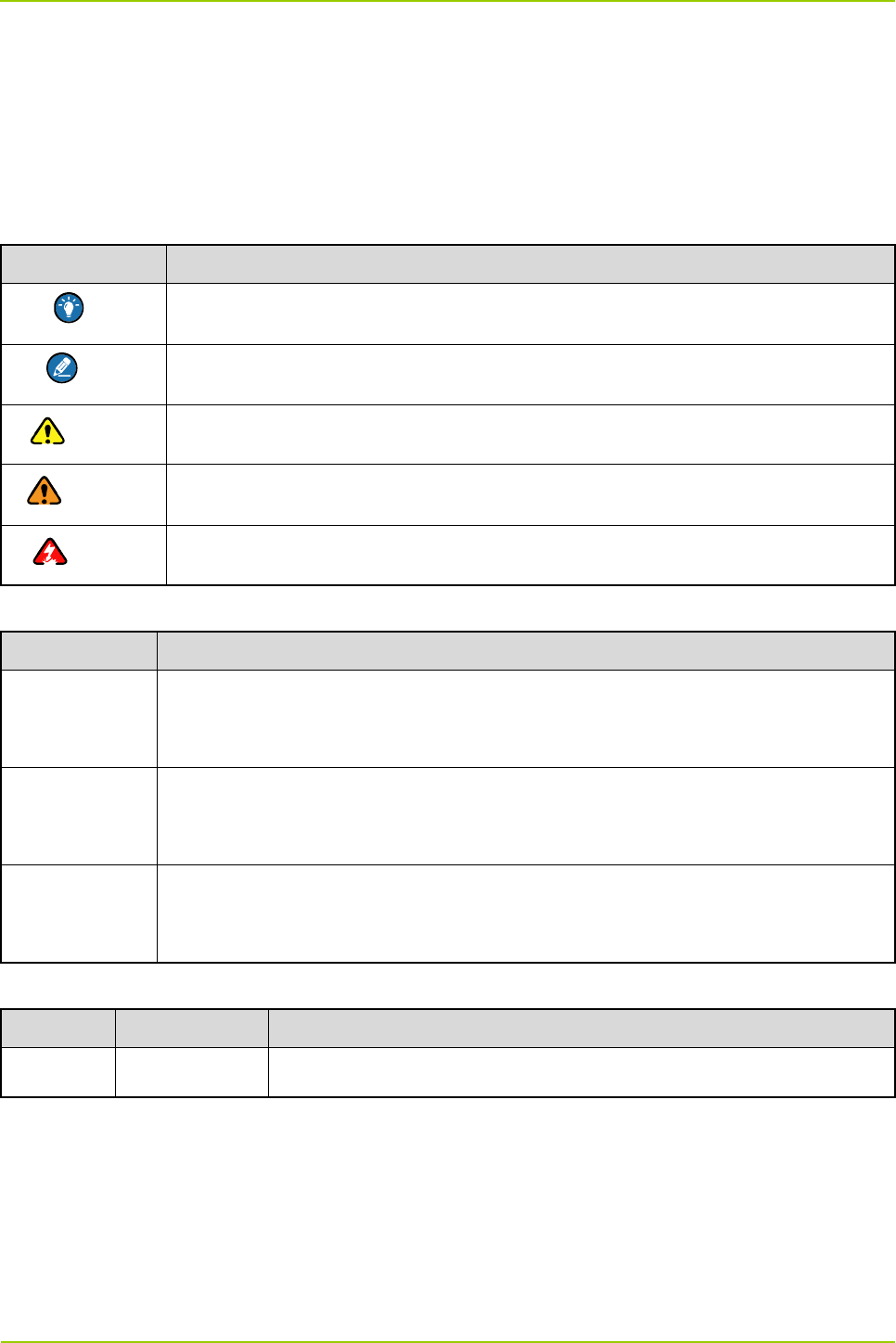
Instructional Icons
Icon Description
Tip Indicates information that can help you make better use of your product.
Note Indicates references that can further describe the related topics.
Caution Indicates situations that could cause data loss or equipment damage.
Warning Indicates situations that could cause minor personal injury.
Danger Indicates situations that could cause major personal injury or even death.
Notational Conventions
Convention Description
“ ” The quotation marks enclose the name of a software interface element. For
example, click “OK”.
Bold The text in boldface denotes the name of a hardware button. For example, press
the PTT key.
-> The symbol directs you to access a multi-level menu. For example, to select “New”
from the “File” menu, we will describe it as follows: File -> New.
Revision History
Version Release Date Description
V00 03-2013 Initial release

Checking Items in the Package User Guide
2
1. Checking Items in the Package
No. Item Qty.
1 PDU 1
2 CHU 4
3 CHU Power Supply 2
4 Switch 1
5 Router 1
6 Server 1
7 PSU 1
8 DIU 1
9 DPU 1
10 COM 1
11 Cabinet Kit (including the 37U cabinet, decorative unit, tray and cable) 1
Table 1-1 Configuration of 4-carrier Base Station

User Guide Hardware Description
3
2. Hardware Description
The DS-6211 base station realizes the following functions:
Processing signaling and service
On the downlink, the server in the base station receives the data packets from the MSO via the
EIB, and sends them to the CHUs via the switch. Then the CHUs generate the downlink RF
signals, which are combined via the COM. Finally, the combined signals are sent to the antenna
via the duplexer for transmission.
On the uplink, the antenna receives the uplink RF signals from the mobile station, and sends
them to the DIU via the duplexer. Then the DIU makes several copies of the signals, and sends
them to the CHUs for generating data packets. Finally, the generated data packets are sent to the
server via the switch, and further sent to the MSO via the EIB.
Supplying power
The AC power from the mains electricity is divided by the PDU to provide power for the CHU power
supply, PSU and other appropriate units in the base station. The CHU power supply converts the AC
voltage to DC voltage to power up the CHU, while the PSU converts the AC voltage to DC voltage to
power up the DIU and other appropriate units such as router.
2.1 PDU
2.1.1 Specifications
Item Specification
Power
Input voltage range 120–240V
Maximum current draw
208V@12.8A (UL, CUL)
120V@16A (UL, CUL)
240V@16A (VDE)
Physical
Dimensions (LXWXD) 447X44.5X57.2mm
Weight 0.98kg
Shipping weight 2.36kg
Environmental
Elevation (above MSL)
Operating: 0–3000m
Storage: 0–15000m
Temperature Operating: 0–45℃
Hardware Description User Guide
4
Item Specification
Storage: –25℃ to 65℃
Relative humidity 0–95%, non-condensing
Approvals/Standards UL, CUL, VDE
Table 2-1 PDU Specifications
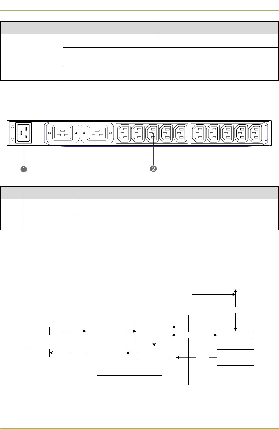
2.1.2 Rear Panel
The rear panel of the PDU is shown in Figure 2-1 and described in Table 2-2.
Figure 2-1 Rear Panel of PDU
No. Name Description
1 Power Inlet 1 inlet
2 Power Outlet 12 outlets
Table 2-2 Descriptions on Rear Panel of PDU
2.2 CHU
The CHU includes the power amplifier module, exciter module, RX module, channel control board and
other mechanical parts. Its logical architecture is shown in Figure 2-2.
Channel
Control Board BSCUEthernet Link
RX Module
Exciter
Module
Power Amplifier
Module
RXDIU
COM TX CHU Power
Supply
13.6V
CHU
Other Mechanical Parts
(including the fan)
RS485 Bus
RS485 Interface
Figure 2-2 Logical Architecture of CHU
2.2.1 Introduction
It is responsible for transmitting and receiving the RF signals and for processing the baseband

User Guide Hardware Description
5
information. The base station has multiple CHUs, each of which is responsible for processing the
information on one carrier.
2.2.2 Specifications
Item Specification
General
Frequency range 400–470MHz
Channel capacity 16
Normal operating voltage 13.6V
Extreme operating voltage
Low: 11.0V
High: 15.6V
Current drain
Standby: ≤1.0A
Transmit: ≤11A
Channel spacing 12.5k
Antenna impedance 50Ω
Duty cycle 100%
Operating temperature –30℃ to +60℃
Storage temperature –40℃ to +85℃
Dimensions (WXHXL) 88x483x366mm
Weight 8.5kg
ESD IEC-801-2KV
LCD Display 220*176pixels, 262000 color, 2.0inch, 4rows
Receiver
Receiver
maximum
usable
sensitivity
(BER)
Normal
–110dBm/BER1%
–118 dBm/BER5%
Extreme –115 dBm/BER5%
Receiver Ultimate (BER) sensitivity –85dBm/BER0%
Receiver BER at high RF input 10dBm/ BER0%
Receiver Dynamic Faded (BER)
–108dBm/BER5%

Hardware Description User Guide
6
Item Specification
sensitivity (8KM/H and 100KM/H)
Receiver analog
maximum usable
sensitivity
Spec
≤–118dBm (12 dB SINAD)
≤–112dBm (20 dB SINAD)
Typical –119dBm
Co-channel rejection 12.5kHz
–12dB
to 0dB
Adjacent channel
selectivity
12.5K ≥65dB
12.5K/digital
≥60dB
Spurious response rejection ≥80dB
Intermodulation
ETSI: ≥70dB
TIA603: ≥75dB
Blocking ≥90dB
Conducted Spurious Emission ≤–57dBm
Radiated Spurious Emission
–57dBm<1GHz
–47dBm>1GHz
Rated audio Power
Rated
Power (8Ω) 0.5W
Maximum
Power 1.0W±20%
Rated audio distortion
Analog ≤3%
Digital ≤5%
Receiver SNR
Analog
≥40dB@12.5kHz
≥43dB@20kHz
≥45dB@2kHz
Digital ≥40dB

User Guide Hardware Description
7
Item Specification
Receiver audio response –3dB to +1dB
Receiver synthesizer
lock time
1st Lo 7ms
2nd Lo 5ms
Transmitter
Frequency stability ≤±0.5ppm
Transmitter output power 5–50W
Occupied
bandwidth
12.5kHz
8.5kHz@3dB
Adjacent channel
power
12.5kHz ≥60dB
Conducted Spur
and harmonic
≤1GHz
≤–6dBm (operating)
≤–57dBm (standby)
>1GHz
≤–30dBm (operating)
≤–47dBm (standby)
Radiated Spur and
harmonic
≤1GHz
≤–36dBm (operating)
≤–57dBm (standby)
>1GHz
≤–30dBm (operating)
≤–47dBm (standby)
Transmit 4FSK
modulation
accuracy
room temp ≤5%
extreme temp ≤10%
Transmit 4FSK
maximum
deviation
room temp 3.7kHz
extreme temp 3.85kHz
4FSK Transmit BER 0%
Transmit FSK and Magnitude Error 5%/1%
4FSK Transmit Modulation Emission
Spectrum Compliant with the interior standard

Hardware Description User Guide
8
Item Specification
Tx Audio distortion
analog ≤3%
Digital ≤5%
Tx Audio S/N
analog
≥40dB@12.5kHz
≥43dB@20kHz
≥45dB@25kHz
Digital ≥40dB
Transmit audio distortion –3dB to +1dB
Transmit transient response Compliant with the ETSI and TIA/EIA standard
Transmit
modulation limiting
12.5kHz ≤2.5kHz
FM modulation
mode
4FSK modulation
mode
12.5k (only data) 7K60FXD
12.5k (both data
and voice) 7K60FXW
CTCSS/DCS
Deviation
12.5kHz 350–600Hz
Duplex
60% Repeater
Audio
Deviation(-30 ℃~
+60)
12.5kHz 1.5±0.2kHz
Repeater Audio Distortion ≤3%
Repeater open sensitivity
–124 to –118dBm (Normal)
–122 to –116dBm (Tight)
Repeater close sensitivity
–126 to –120dBm (Normal)
–124 to –118dBm (Tight)
Repeater Audio analog ≥43dB@25kHz
(N/A)
User Guide
Hardware Description
9
Item Specification
SNR ≥40dB@12.5kHz
Digital ≥40dB
SYNC
Carrier
synchronous
range
analog ±4kHz
Digital ±8kHz
Table 2-3 CHU Specifications
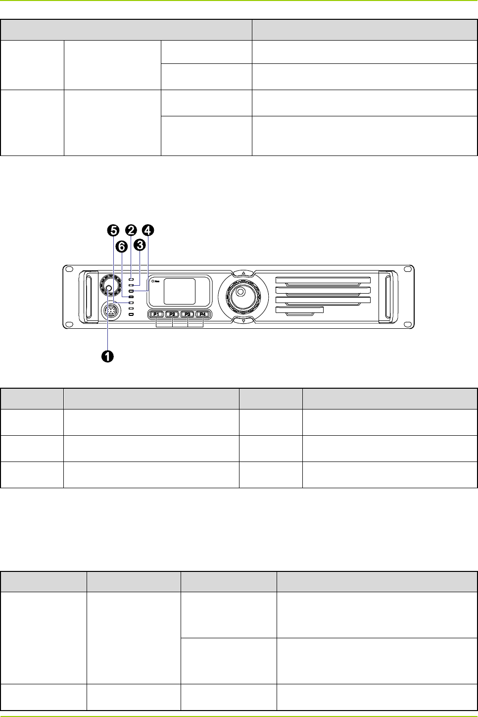
2.2.3 Front Panel
The front panel of the CHU is shown in Figure 2-3.
Figure 2-3 Front Panel of CHU
No. Name No. Name
1 PWR Indicator 2 Digital Indicator
3 TX-A Indicator 4 RX-A Indicator
5 TX-B Indicator 6 RX-B Indicator
Table 2-4 Descriptions on Front Panel of CHU
2.2.4 LED Indicator
The CHU indicators are described in Table 2-5.
LED Indicator Color Status Description
PWR Indicator Yellow
Glowing solidly
The CHU is supplied with power
normally.
Off
The CHU is not supplied with power
normally.
Digital Indicator Blue Flashing The CHU runs normally.

Hardware Description
User Guide
10
LED Indicator Color Status Description
Off The CHU does not run normally.
TX-A Indicator Red
Flashing The CHU is transmitting data on time slot
1.
Off
No data is being transmitted on time slot
1.
RX-A Indicator Yellow
Flashing The CHU is receiving carrier signals on
time slot 1.
Off
No carrier signal is being received on
time slot 1.
TX-B Indicator Red
Flashing The CHU is transmitting data on time slot
2.
Off
No data is being transmitted on time slot
2.
RX-B Indicator Yellow
Flashing The CHU is receiving carrier signals on
time slot 2.
Off
No carrier signal is being received on
time slot 2.
Table 2-5 Descriptions on CHU Indicators
Note
If the PWR indicator is glowing solidly and the Digital indicator is flashing, it means the CHU goes to
the sleep mode. In this mode, the CHU can still receive inbound data (the RX-A/RX-B indicator
flashes).
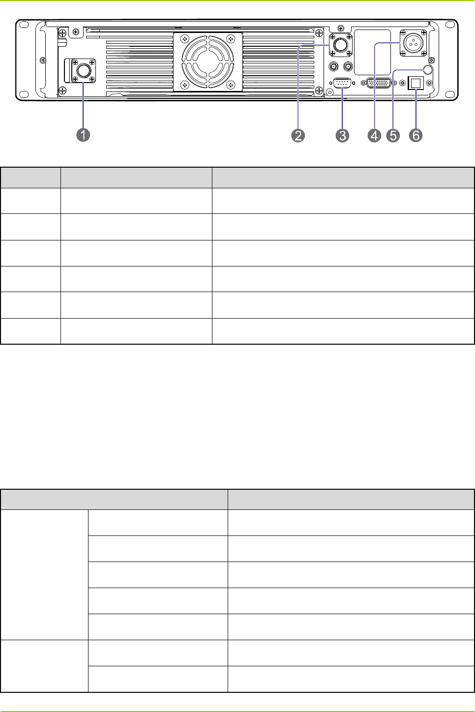
2.2.5 Rear Panel
The rear panel of the CHU is shown in Figure 2-4 and described in Table 2-6.
User Guide
Hardware Description
11
Figure 2-4 Rear Panel of CHU
No. Name Description
1 TX Antenna Interface N connector (female)
2 RX Antenna Interface N connector (female)
3 Monitor Interface DB9 connector
4 DC Power Inlet 13.6V±5% DC, ≤170W
5 Ground Terminal Screw terminal
6 Ethernet Interface RJ45 connector
Table 2-6 Descriptions on Rear Panel of CHU
2.3 CHU Power Supply
2.3.1 Introduction
Each CHU power supply can power up two CHUs.
2.3.2 Specifications
Each CHU power supply contains two power modules, whose specifications are described in Table 2-7.
Item Specification
Input Property
Operating Voltage 100/220V AC
Extreme Voltage 90–264V AC
Frequency 47–63Hz
Max. Current <6.5A (input voltage: 100–130V AC)
Max. Surge Current <50A (230V AC)
Output Property
Voltage 13.8V DC
Rated Current 16A

Hardware Description
User Guide
12
Item Specification
Efficiency ≥82% (input voltage: 230V AC)
Ripple Voltage <150mVp-p
Environment
Property
Normal Operating
Temperature 15℃ to 35℃
Extreme Operating
Temperature –30℃ to +60℃
Storage Temperature –40℃ to +85℃
Operating Humidity <90%RH
Altitude <2000m
MTBF 100,000 hours
Vibration 10–500Hz, 2G, 60 minutes, X/Y/Z directions
Protection
Property
Over-voltage Protection 15–18V, self-recover
Over-power Protection Self-recover
Short Circuit Protection Hiccup mode
Safety
Requirement Standard CE60950/UL60950
EMC
EMI EN 55022 class B
EMS EN 55024
Standby Power Consumption ≤5W (input voltage: 240V AC)
Table 2-7 CHU Power Supply Specifications
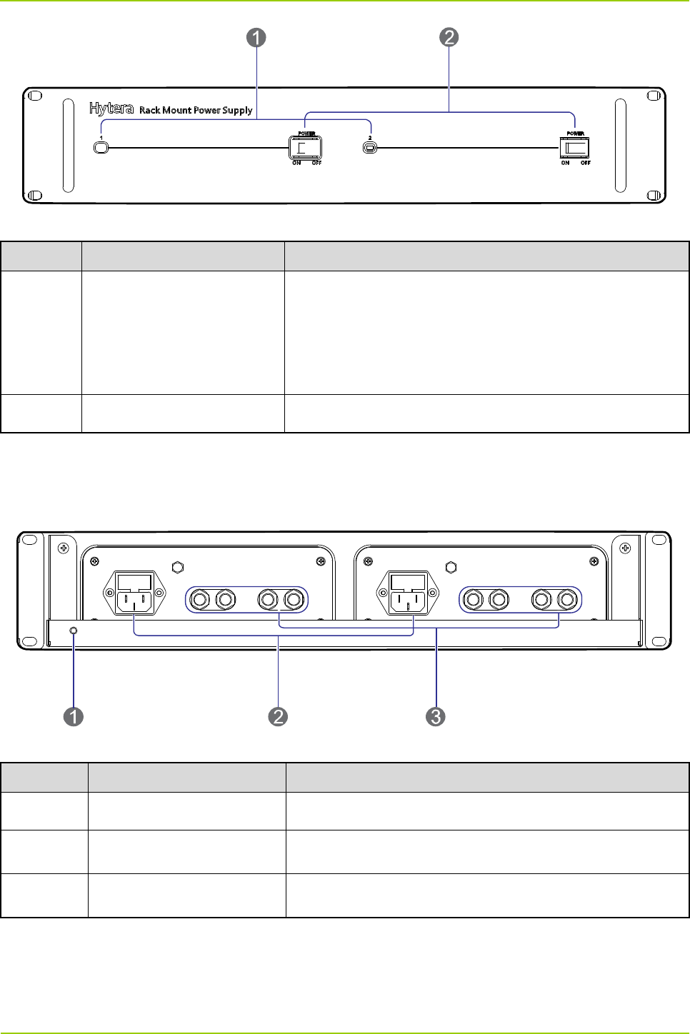
2.3.3 Front Panel
The front panel of the CHU power supply is shown in Figure 2-5 and described in Table 2-8.
User Guide
Hardware Description
13
Figure 2-5 Front Panel of CHU Power Supply
No. Name Description
1 PWR Indicator
If the PWR indicator glows green solidly, it means the
corresponding power module supplies power normally; if
the indicator goes off, it means the corresponding power
module does not supply power normally.
2 On/Off Switch Double-pole-double-throw switch
Table 2-8 Descriptions on Front Panel of CHU Power Supply
2.3.4 Rear Panel
The rear panel of the CHU power supply is shown in Figure 2-6 and described in Table 2-9.
Figure 2-6 Rear Panel of CHU Power Supply
No. Name Description
1 Ground Terminal ≤0.1Ω, ≥2.5mm2, screw terminal
2 AC Power Inlet 110/220V AC, ≤486W, 3-pin
3 DC Power Outlet 13.6V±5% DC, 2 paths, ≥170W/path, terminal connector
Table 2-9 Descriptions on Rear Panel of CHU Power Supply
Hardware Description
User Guide
14
2.4 Switch
2.4.1 Introduction
The switch provides media for communication within the base station.
2.4.2 Specifications
Item Specification
Standard and Protocol
IEEE 802.3 10BASE-T Ethernet
IEEE 802.3u 100BASE-TX Fast Ethernet
CSMA/CD Ethernet
Data Transmission Rate
Ethernet: 10Mbps (half duplex), 20Mbps (full duplex)
Fast Ethernet: 100Mbps (half duplex), 200Mbps (full duplex)
Network Media
10Base-T: UTP/STP Cat3 or above (≤100m)
100Base-TX: UTP/STP Cat5 or above (≤100m)
Transmission Way Store and forward
AC Input 100–240V 50/60Hz 0.6A
Operating Temperature 0℃ to +40℃
Storage Temperature –40℃ to +70℃
Operating Humidity 10%–90%RH (non-condensing)
Storage Temperature 5%–90%RH (non-condensing)
Table 2-10 Switch Specifications
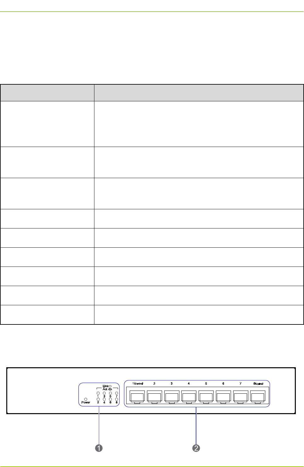
2.4.3 Front Panel
The front panel of the switch is shown in Figure 2-7 and described in Table 2-11.
Figure 2-7 Front Panel of Switch
User Guide
Hardware Description
15
No. Name No. Name
1 LED Indicator 2 Ethernet Interface
Table 2-11 Descriptions on Front Panel of Switch
2.4.4 LED Indicator
The switch indicators are described in Table 2-12.
LED
Indicator Color Status Description
Power Red
Glowing solidly
The switch is supplied with power
normally.
Off The switch is not supplied with power
normally.
Link/Act Green
Glowing solidly
A device is connected to the
corresponding interface.
Flashing Data is being received or sent via the
corresponding interface.
Off
No device is connected to the
corresponding interface.
Table 2-12 Descriptions on Switch Indicators
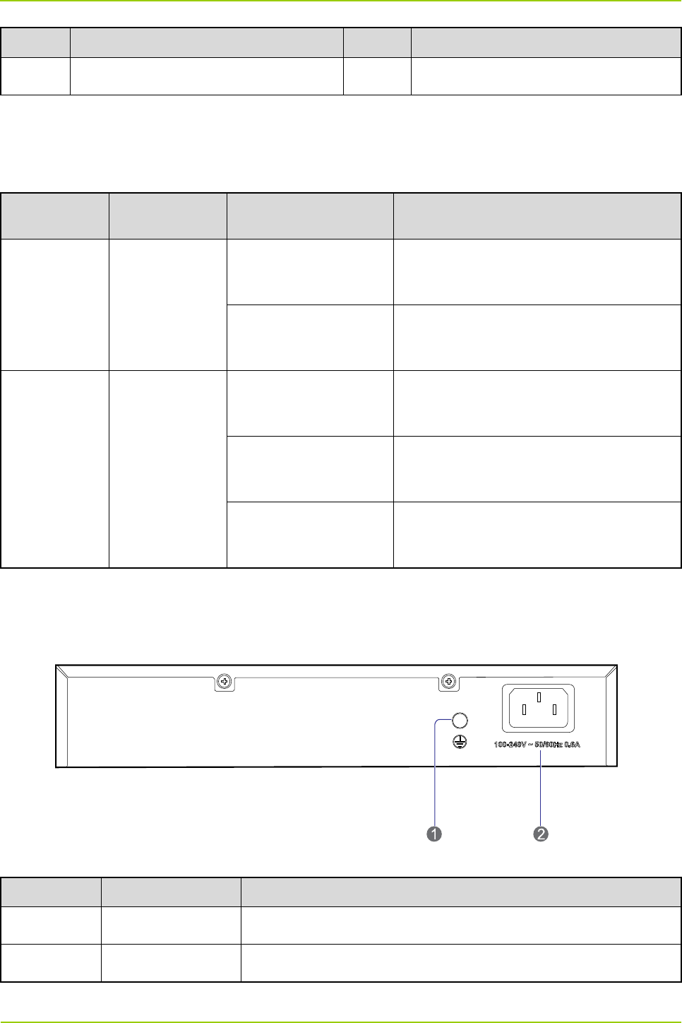
2.4.5 Rear Panel
The rear panel of the switch is shown in Figure 2-8 and described in Table 2-13.
Figure 2-8 Rear Panel of Switch
No. Name Description
1 Ground Terminal Screw
2 Power Inlet 100–240V AC 50/60Hz 0.6A
Table 2-13 Descriptions on Rear Panel of Switch
Hardware Description
User Guide
16
2.5 Router
2.5.1 Introduction
The router provides media for communication between the base station and MSO.
2.5.2 Specifications
Item Specification
Repeat Performance 150Kpps
Memory 256M (DDR2)
Flash 256M
USB 1
CON 1
Communication
Interface 2 megabit Ethernet interfaces, 4 megabit switch interfaces
Max. Power
Consumption 12W
Rated Input Voltage 100–240V 50/60Hz
Ambient Temperature
Ambient Temperature
Ambient Humidity Ambient Humidity
Table 2-14 Router Specifications
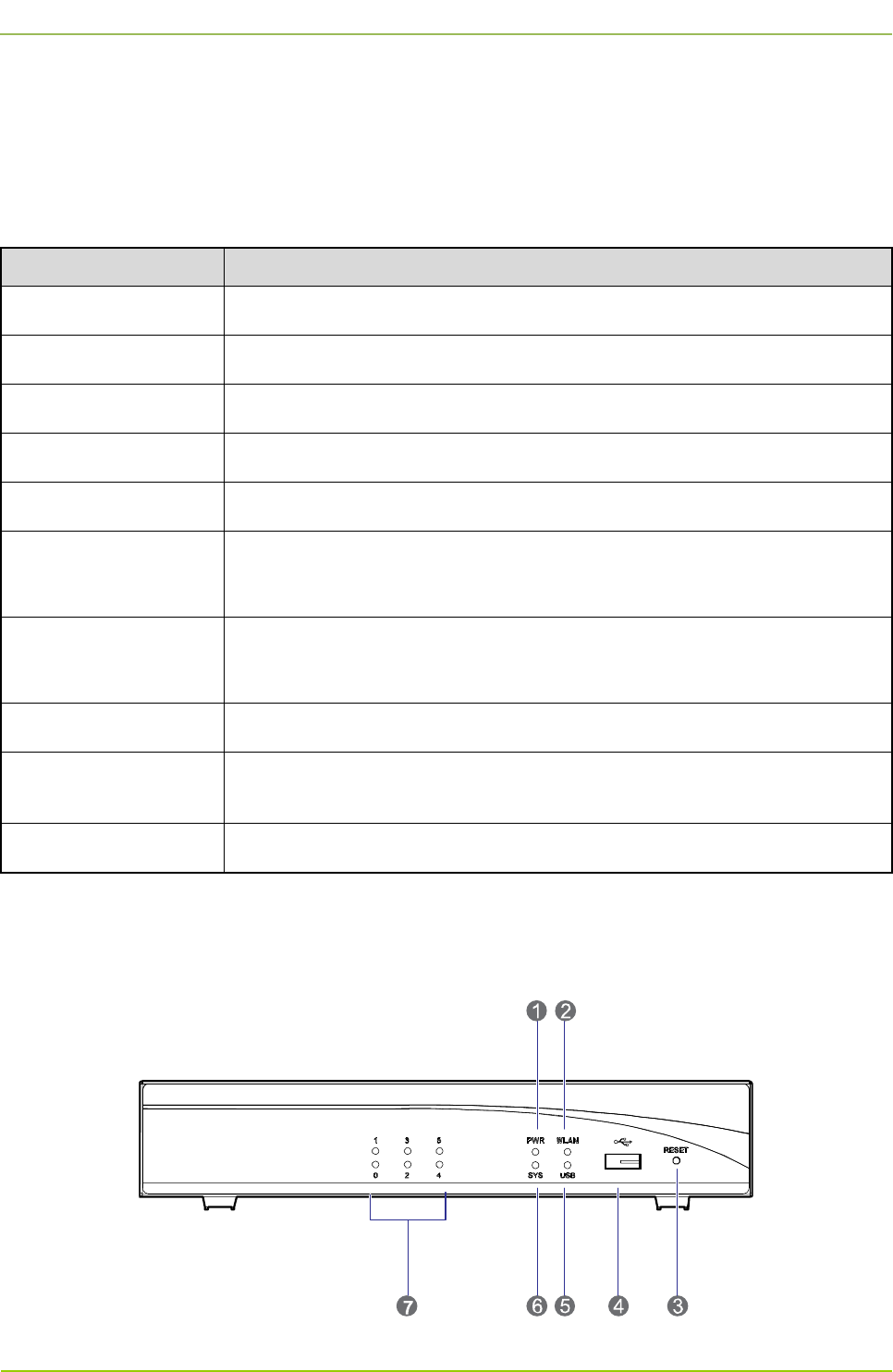
2.5.3 Front Panel
The front panel of the router is shown in Figure 2-9 and described in Table 2-15.
Figure 2-9 Front Panel of Router

User Guide
Hardware Description
17
No. Name No. Name
1 PWR Indicator 2 WLAN Indicator (not used)
3 RESET Button 4 USB Port
5 USB Indicator 6 SYS Indicator
7 Ethernet Indicator / /
Table 2-15 Descriptions on Front Panel of Router
2.5.4 LED Indicator
The router indicators are described in Table 2-16.
LED Indicator Status Description
PWR
Glowing solidly The router is supplied with power normally.
Off The router is not supplied with power normally.
SYS
Green LED flashing rapidly The router is starting.
Green LED flashing slowly The router is running normally.
Yellow LED flashing rapidly The router malfunctions.
Off The router runs abnormally.
0–5
Off The Ethernet is not connected.
Glowing solidly The Ethernet is connected.
Flashing Data is being transferred between the router and
Ethernet.
USB
Glowing solidly The USB port is in use.
Off The USB port is not in use.
Table 2-16 Descriptions on Router Indicators
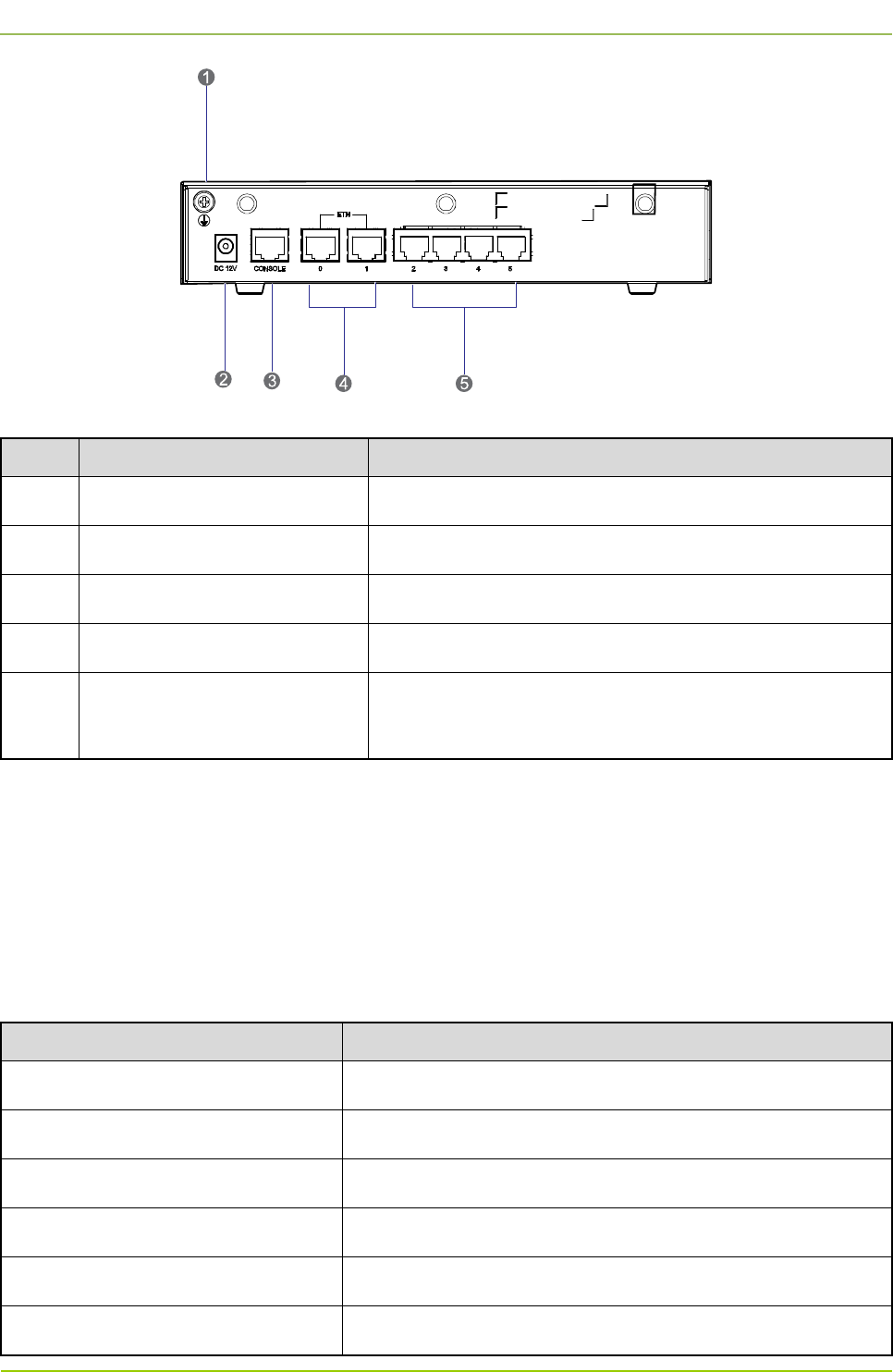
2.5.5 Rear Panel
The rear panel of the router is shown in Figure 2-10 and described in Table 2-17.
Hardware Description
User Guide
18
Figure 2-10 Rear Panel of Router
No. Name Purpose
1 Ground Terminal To connect with the ground cable.
2 Power Inlet To connect with the power adapter.
3 Console Interface To connect with the PC via the serial cable.
4 Fixed Ethernet Interface (0–1) Uplink 3-layer Ethernet interface to connect with the WAN.
5 Fixed Switch Interface (2–5) Downlink 2-layer Ethernet interface to connect with the PC
or switch.
Table 2-17 Descriptions on Rear Panel of Router
2.6 Server
2.6.1 Introduction
It is responsible for mobility management, call control, radio resource management and interface control
between the base station and MSO.
2.6.2 Specifications
Item Specification
Form Factor RACK
CPU Frequency 3.10GHz
Processors Quad-core Intel® Xeon®E-1220 processors
Processor Sockets 1
Front Side Bus or HyperTransport DMI (Direct Media Interface)
Cache 8MB
User Guide
Hardware Description
19
Item Specification
Chipset Intel® C216 chipset
Memory 4GB DDR3 1333MHz
I/O Slots 1 PCIe x16 G2 slot
Hard Drives 3.5 inch SATA (7.2K rpm): 500GB
Network Interface Cards Dual Port Adapter, Gigabit Ethernet NIC, PCIe x4
Power Supply Single-cabled power supply (250W)
Video Matrox® G200eW w/ 8MB memory
Remote Management iDRAC6 optional
Operating Systems OS-LINUX
Table 2-18 Server Specifications
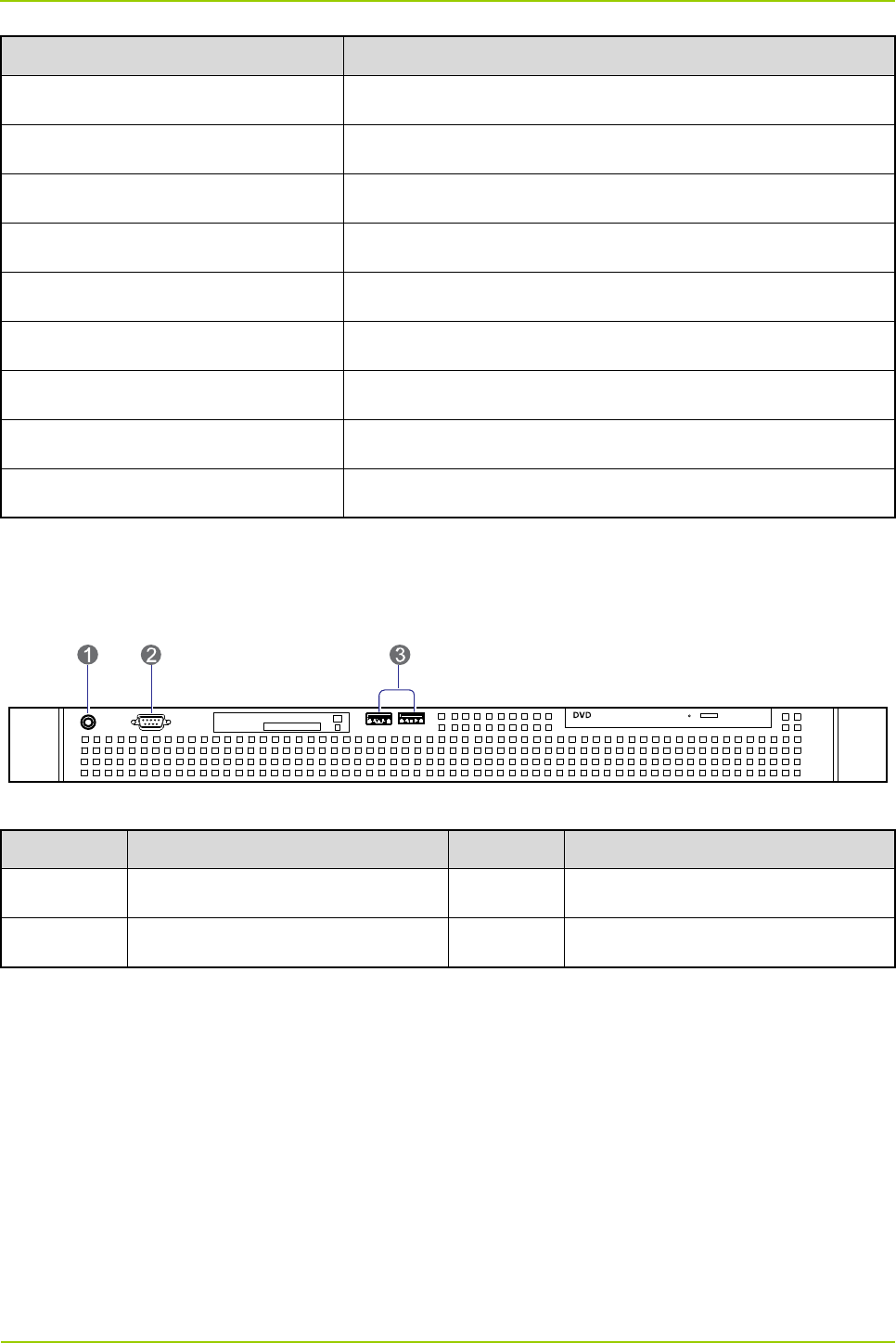
2.6.3 Front Panel
The front panel of the server is shown in Figure 2-11 and described in Table 2-19.
Figure 2-11 Front Panel of Server
No. Name No. Name
1 On/Off Switch 2 VGA Connector
3 USB Port / /
Table 2-19 Descriptions on Front Panel of Server
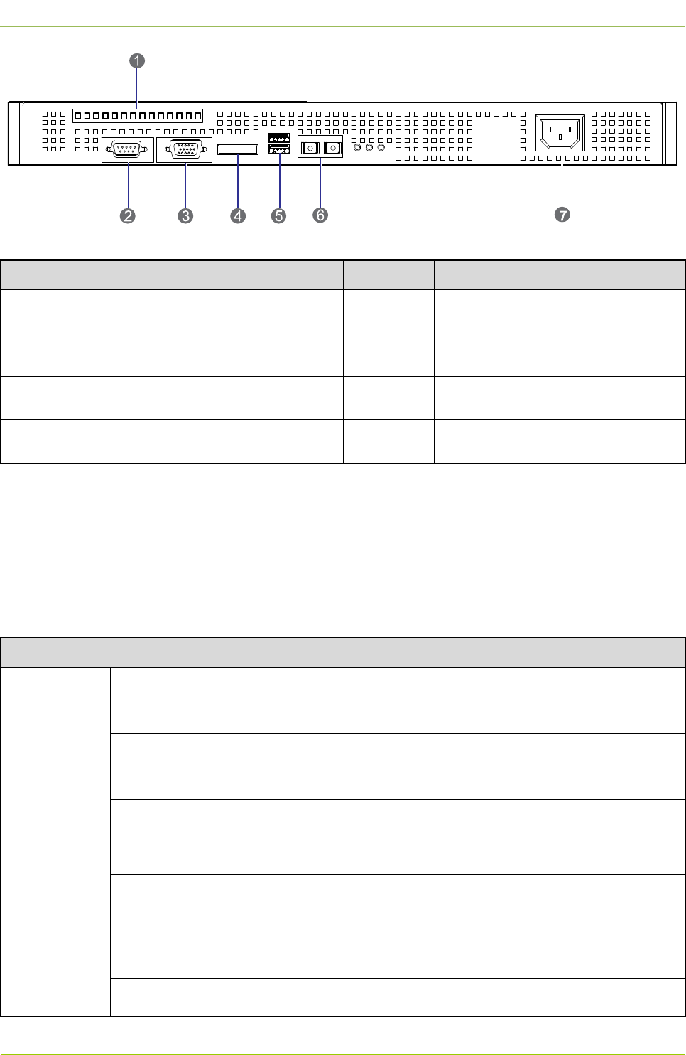
2.6.4 Rear Panel
The rear panel of the server is shown in Figure 2-12 and described in Table 2-20.
Hardware Description
User Guide
20
Figure 2-12 Rear Panel of Server
No. Name No. Name
1 PCIe Interface 2 Serial Port
3 VGA Connector 4 E-SATA Interface
5 USB Port 6 100/1000 Mbps Ethernet Interface
7 AC Power Inlet / /
Table 2-20 Descriptions on Rear Panel of Server
2.7 PSU
2.7.1 Introduction
The PSU converts the AC voltage to DC voltage, to supply the internal units in the base station.
2.7.2 Specifications
Item Specification
Input Property
Normal Operating
Voltage 100/220V AC
Extreme Operating
Voltage 85–265V AC
Frequency 47–63Hz
Max. Current <4A (input voltage: 115V AC)
Max. Surg
e Current
(<2ms)
<30A (115V AC), <50A (230V AC)
Output
Property
Voltage 12V
Max. Current 10A

User Guide
Hardware Description
21
Item Specification
Max. Power 120W
Switching Frequency 100KHz
Efficiency ≥86%
Hold Time ≥10ms
Ripple Voltage <64mVp-p
Environment
Property
Normal Operating
Temperature 15℃ to 35℃
Extreme Operating
Temperature –30℃ to 60℃
Storage Temperature –40℃ to 85℃
Operating Humidity <95%RH
Altitude <2000m
MTBF 100,000 hours
Vibration 10–500Hz, 2G, 60 minutes, X/Y/Z directions
Protection
Property
Over-voltage
Protection Self-recover via the clamping diode
Over-power Protection Self-recover
Short Circuit
Protection Self-recover
Safety
Requirement Standard CE60950/UL60950
EMC
EMI EN 55022 class B
EMS EN 55024
Table 2-21 PSU Specifications
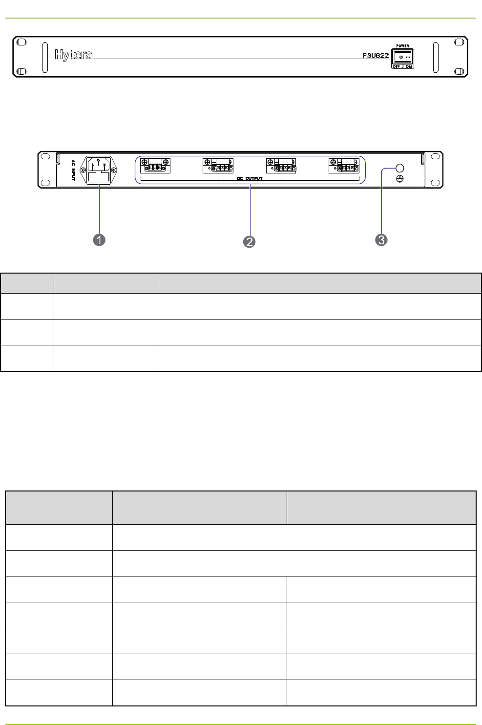
2.7.3 Front Panel
The front panel of the PSU is shown in Figure 2-13.
Hardware Description
User Guide
22
Figure 2-13 Front Panel of PSU
2.7.4 Rear Panel
The rear panel of the PSU is shown in Figure 2-14 and described in Table 2-22.
Figure 2-14 Rear Panel of PSU
No. Name Description
1 AC Power Inlet 110/220V AC, ≤120W, 3-pin
2 DC Power Outlet 12V±5% DC, terminal connector
3 Ground Terminal ≤0.1Ω, ≥2.5mm2, screw terminal
Table 2-22 Descriptions on Rear Panel of PSU
2.8 DIU
2.8.1 Introduction
It divides the RX signals into four parts and provides them to the CHUs respectively.
2.8.2 Specifications
Item Specification under Normal
Temperature (+15
℃
to +35
℃
)
Specification under Extreme
Temperature (–30
℃
to +60
℃
)
Frequency Range 400–470MHz
Operating Bandwidth 5MHz
In-band Gain 7.5±0.5dB 7.5±1.5dB
Noise Figure ≤1.5dB ≤1.8dB
Input VSWR ≤1.40 ≤1.50
Output VSWR ≤1.30 ≤1.50
In-band Ripple (P-P) ≤0.5dB ≤0.7dB
User Guide
Hardware Description
23
Item Specification under Normal
Temperature (+15
℃
to +35
℃
)
Specification under Extreme
Temperature (–30
℃
to +60
℃
)
Port Unbalance
(P-P)
≤1.0dB
Isolation ≥23dB ≥20dB
Cross Modulation ≥-60dBc@–20dBm ≥-57dBc@–20dBm
Operating Voltage 12–13.8V DC
Operating Current ≤300mA
Allowed Input Power ≤10dBm
Impedance 50Ω
Connector Type N connector (female)
Operating Humidity 5%–95%RH
Operating
Temperature –30℃ to +60℃
Storage
Temperature –40℃ to +85℃
Max. Power
Consumption 4W
Table 2-23 DIU Specifications
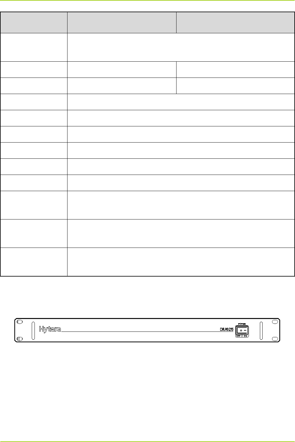
2.8.3 Front Panel
The front panel of the DIU is shown in Figure 2-15.
Figure 2-15 Front Panel of DIU
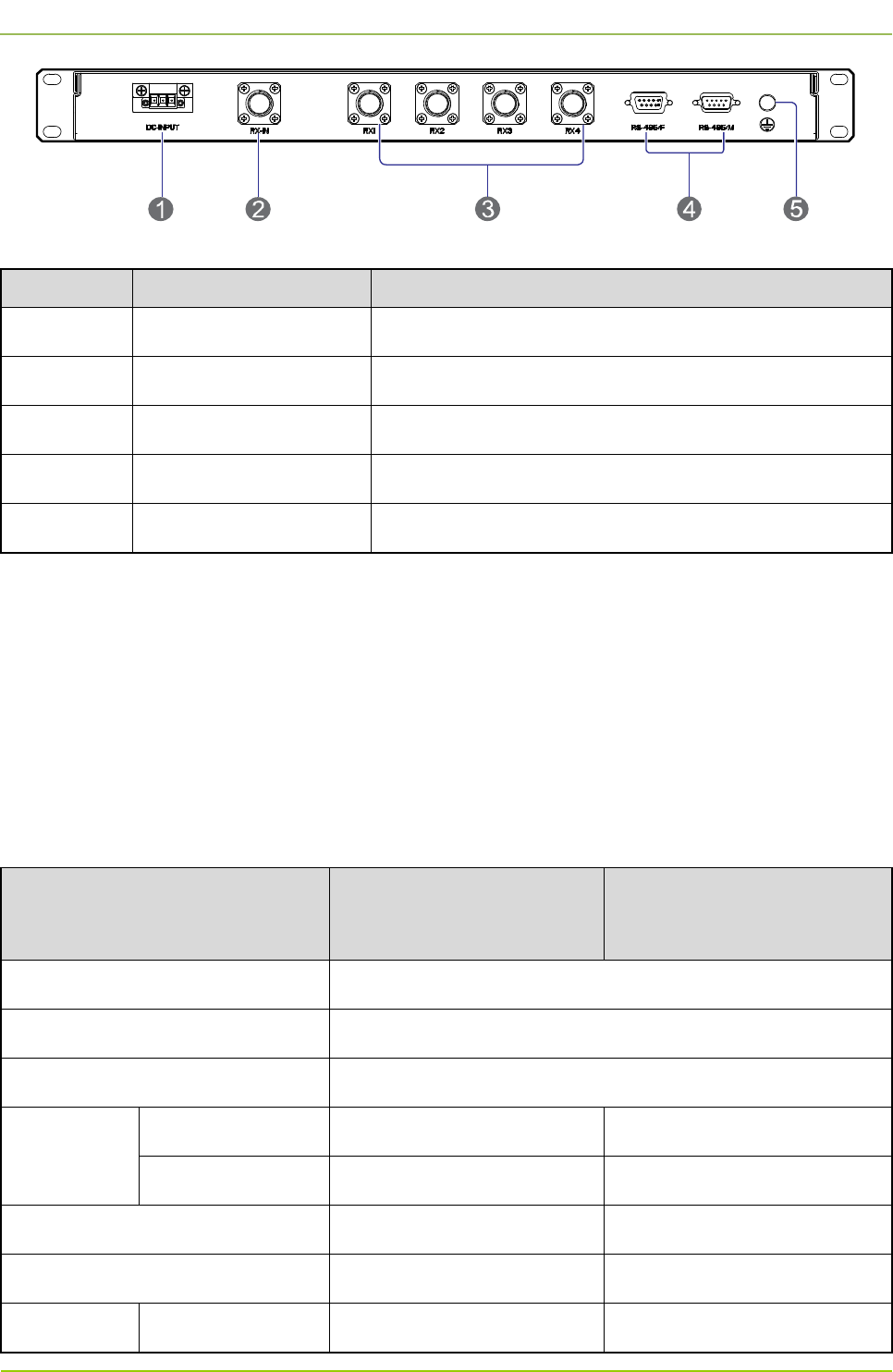
2.8.4 Rear Panel
The rear panel of the DIU is shown in Figure 2-16 and described in Table 2-24.
Hardware Description
User Guide
24
Figure 2-16 Rear Panel of DIU
No. Name Description
1 DC Power Inlet 12V DC, ≤15W, 3-pin
2 RF Input Interface N connector (female)
3 RF Output Interface To connect with the CHU. N connector (female)
4 Monitor Interface RS485 interface, DB9 connector (male/female)
5 Ground Terminal ≤0.1Ω, ≥2.5mm2, screw terminal
Table 2-24 Descriptions on Rear Panel of DIU
2.9 DPU
2.9.1 Introduction
The duplexer realizes the following functions:
On the uplink, the duplexer sends the RX signal from the antenna to the DIU via the RX interface.
On the downlink, the duplexer sends the TX signal from the COM to the antenna via the TX interface
2.9.2 Specifications
Item
Specification under Normal
Temperature (+15
℃
to
+35
℃
)
Specification under Extreme
Temperature (–30
℃
to
+60
℃
)
Frequency Range 400–470MHz
Operating Bandwidth 5MHz
Duplex Spacing 10MHz
Insertion
Loss
350–420MHz ≤1.1dB ≤1.3dB
420–480MHz ≤1.2dB ≤1.4dB
In-band Ripple (P-P) within 5MHz ≤0.4dB ≤0.6dB
Input/Output VSWR ≤1.25 ≤1.50
Out-of-band
Out of band:
RX: ≥80dB RX: ≥75dB
User Guide
Hardware Description
25
Item
Specification under Normal
Temperature (+15
℃
to
+35
℃
)
Specification under Extreme
Temperature (–30
℃
to
+60
℃
)
Rejection +5MHz TX: ≥60dB TX: ≥55dB
Out of band:
–5MHz
RX: ≥60dB
TX: ≥80dB
RX: ≥55dB
TX: ≥75dB
Out of band:
+10MHz
RX: ≥80dB
TX: ≥75dB
RX: ≥75dB
TX: ≥70dB
Out of band:
–10MHz
RX: ≥75dB
TX: ≥80dB
RX: ≥70dB
TX: ≥75dB
Isolation
RX-TX Band ≥50dB ≥45dB
RX Band ≥80dB ≥75dB
TX Band ≥80dB ≥75dB
OIP3 ≥80dBm (△f=250KHz)
Operating Temperature +15℃ to +35℃ –30℃ to +75℃
Storage Temperature –40℃ to +85℃
Operating Humidity 5%–95%
Impedance 50Ω
Connector Type N connector (female)
Table 2-25 DPU Specifications
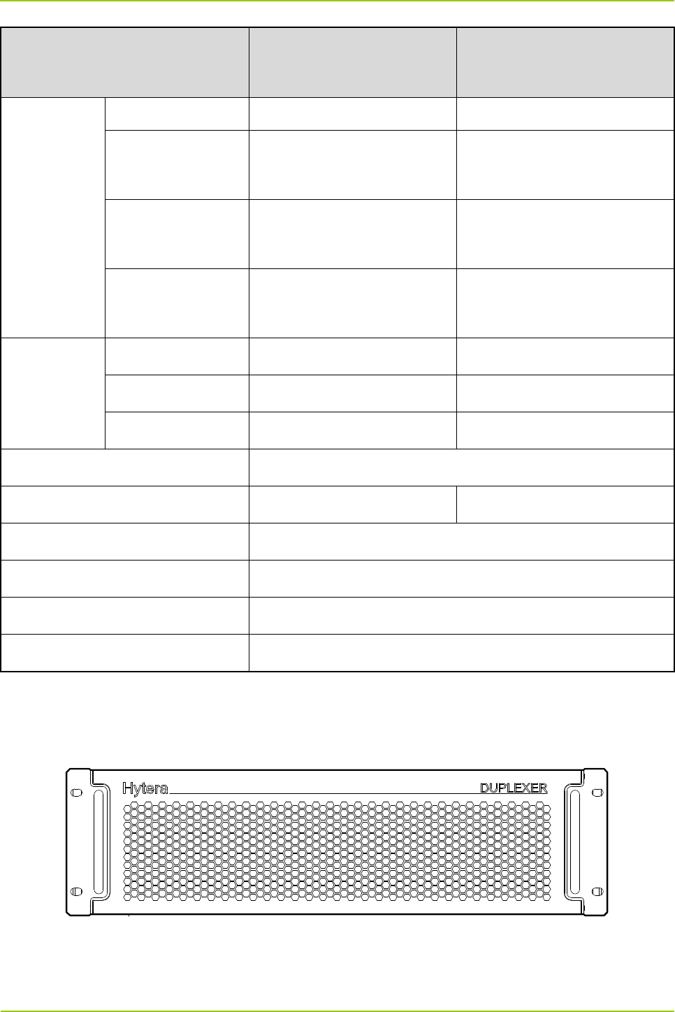
2.9.3 Front Panel
The front panel of the DPU is shown in Figure 2-17.
Figure 2-17 Front Panel of DPU
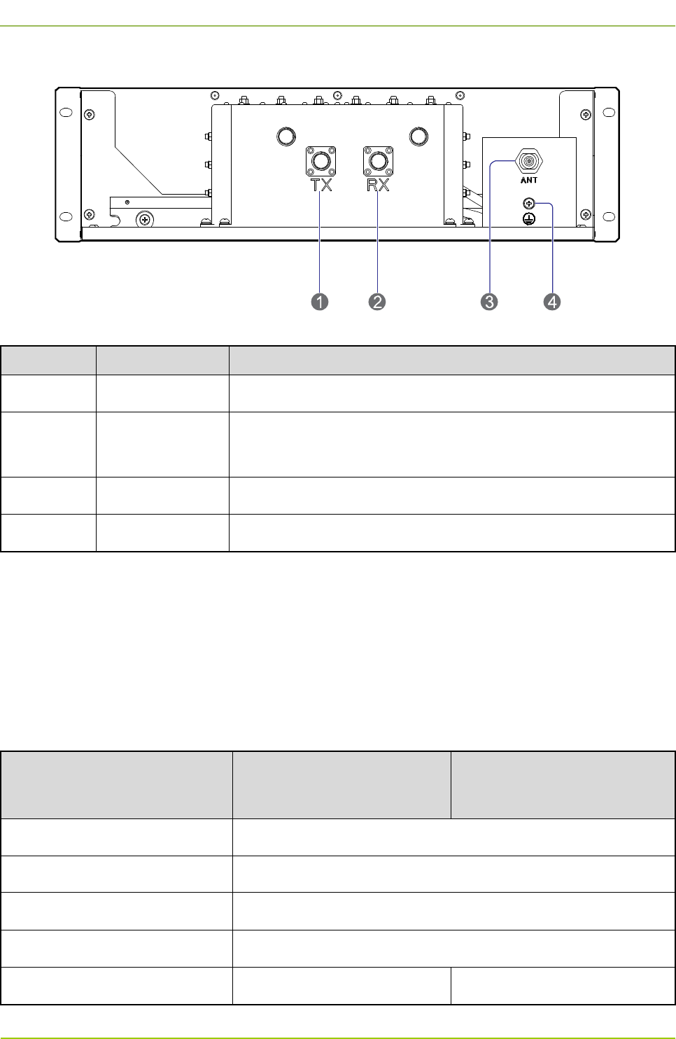
2.9.4 Rear Panel
Hardware Description
User Guide
26
The rear panel of the DPU is shown in Figure 2-18 and described in Table 2-26.
Figure 2-18 Rear Panel of DPU
No. Name Description
1 TX Input Interface N connector (female)
2
RX Output
Interface N connector (female)
3 Duplex Interface N connector (female)
4 Ground Terminal ≤0.1Ω, ≥2.5mm2, screw terminal
Table 2-26 Descriptions on Rear Panel of DPU
2.10 COM
2.10.1 Introduction
It combines the signals received from multiple CHUs, and sends them to the duplexer via the output
interface.
2.10.2 Specifications
Item
Specification under Normal
Temperature (+15
℃
to
+35
℃
)
Specification under Extreme
Temperature (–30
℃
to +60
℃
)
Frequency Range 400–470MHz
Operating Bandwidth 5MHz
Channel Spacing ≥250kHz
Channel Capacity 4
Insertion Loss ≤3.0dB ≤3.5dB

User Guide
Hardware Description
27
Item
Specification under Normal
Temperature (+15
℃
to
+35
℃
)
Specification under Extreme
Temperature (–30
℃
to +60
℃
)
Out-of-band
Rejection
Out of band:
±250kHz
≥10dB /
Out of band:
±500kHz
≥15dB /
VSWR
Input ≤1.25 ≤1.50
Output ≤1.50 ≤1.80
Isolation
Isolation between
Input Interfaces
≥75dB
Reverse Isolation ≥65dB
Intermodulation Attenuation ≤-65@2CH (Pin=47dBm, △f=250kHz)
Harmonics Suppression ≥80dBc
Mean Power ≥100W (per channel)
Operating Temperature +15℃ to +35℃ –30℃ to +75℃
Storage Temperature –40℃ to +85℃
Operating Humidity 5%–95%RH
Impedance 50Ω
Connector Type N connector (female)
Table 2-27 COM Specifications
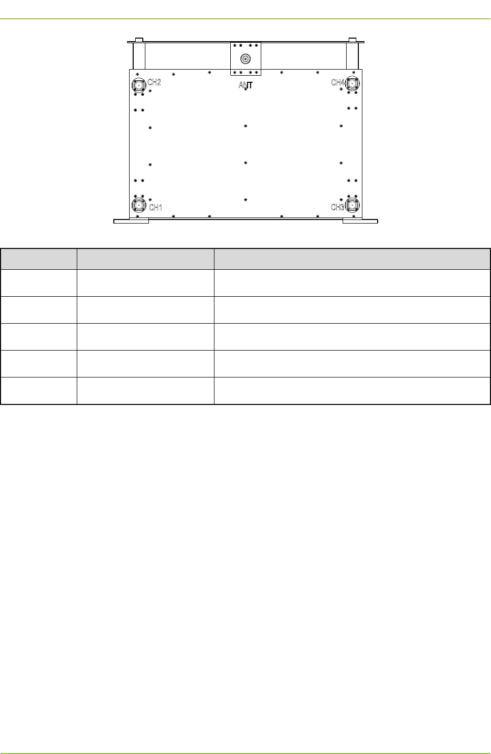
2.10.3 Rear Panel
The rear panel of the COM is shown in Figure 2-19 and described in Table 2-28.
Hardware Description
User Guide
28
Figure 2-19 Rear Panel of COM
Name Description Remark
CH1 Carrier input interface 1 N connector (female)
CH2 Carrier input interface 2 N connector (female)
CH3 Carrier input interface 3 N connector (female)
CH4 Carrier input interface 4 N connector (female)
ANT Combined output interface N connector (female)
Table 2-28 Descriptions on Rear Panel of COM

User Guide
Hardware Installation
29
3. Hardware Installation
3.1 Safety Information
Before performing any operation, read the following precautions and operation instructions carefully to
ward off potential risks.
3.1.1 Electrical Safety
Danger
Direct contact or indirect contact (through moist objects) with the high voltage or mains electricity may
result in fatal danger.
Never wear conductive objects such as watches, bracelets or rings during operation.
Do use special tools during high voltage or AC operations.
Take necessary measures to prevent entry of moisture into the equipment operating under moist
environment.
Make sure the equipment is well grounded to avoid damage as a result of lightning strikes.
Disconnect the equipment from the power supply before installing or uninstalling it.
Check the label on the cable to ensure correct connection.
Make sure that the equipment is well grounded before connecting it to the power supply.
Disconnect the equipment from the power supply if you find water or other liquids on the cabinet.
Make sure all switches of the power distribution box are toggled to the “Off” position before installing
any unit in the cabinet.
3.1.2 Working Aloft
Warning
Exert sufficient cautions to prevent any object from falling when working aloft.
Take sound safety actions such as wearing the hamlet and safety belt properly.
Do wear heat-retaining clothes for working in cold areas.
Make sure that the ladder is safe for use, and overload is strictly prohibited.
The slant of the ladder is suggested to be 75°. When using a ladder, place it on a stable ground, and
take protective measures on the base part of the ladder for skid resistance.
Handle and use all instruments and tools with care to avoid falling.
Hardware Installation
User Guide
30
3.2 Installation Preparation
3.2.1 Technical Files
The technical files required for the hardware installation are listed in Table 3-1.
File Type File Name Description
Instructional
file for
installation
Network Planning Drawing
Provided by the R&D engineers or
marketing personnel
Site Survey Report Provided by the investigator according to
the on-site investigation
Guidebook
DS-6211 Lite Digital Trunking System
Product Description
Shipped with the equipment
DS-
6211 Base Station Hardware
Description
DS-6211 Base Statio
n Hardware
Installation Guide
Other file Packing List Shipped with the equipment
Table 3-1 Technical Files
Note
The Project Construction Scheme may be required for the hardware installation according to the
actual needs.
3.2.2 Personnel
Only the qualified personnel are allowed to install and configure the equipment. The number of required
engineers is subject to the specific project.
3.2.3 Instruments and Tools
Before hardware installation, you shall prepare the instruments and tools listed in Table 3-2.
General Tools
Hex screwdriver (T9), slot
type screwdriver (2#), Phillips
screwdriver (PH0, PH2), 8″ wrench (2 pcs), 15″ wrench (2 pcs),
expanding pliers, sealant gun, electric iron, diagonal pliers, claw
hammer, paper knife, power strip and A type ladder
Special Tools Anti-static wrist strap, cable peeler, crimping pliers and terminal
pliers
User Guide
Hardware Installation
31
Meters Multimeter and power meter
Table 3-2 Instruments and Tools
3.2.4 Unpacking the Base Station
Checking the Package Container
After the equipment arrives at the installation site, you should do the following check tasks:
Check against the Packing List on the package container.
If any item is inconsistent with the Packing List, please contact us immediately.
Check whether the package container is in good condition and not placed upside down during
transportation.
If the package container is damaged seriously or soaked, please contact us immediately.
Note
Keep the package container, equipment and packing materials properly, and photograph them for
reference.
After the above check tasks are completed, you can unpack the base station.
Unpacking the Wooden Case
Caution
Avoid collision with the gate or wall while carrying the equipment.
Never touch the parts or unpainted surfaces with sweat-soaked or dirty gloves.
Carry the wooden case into or near the equipment room before unpacking. This can prevent the
cabinet from being damaged.
Tools Claw hammer, slot type screwdriver and wrench
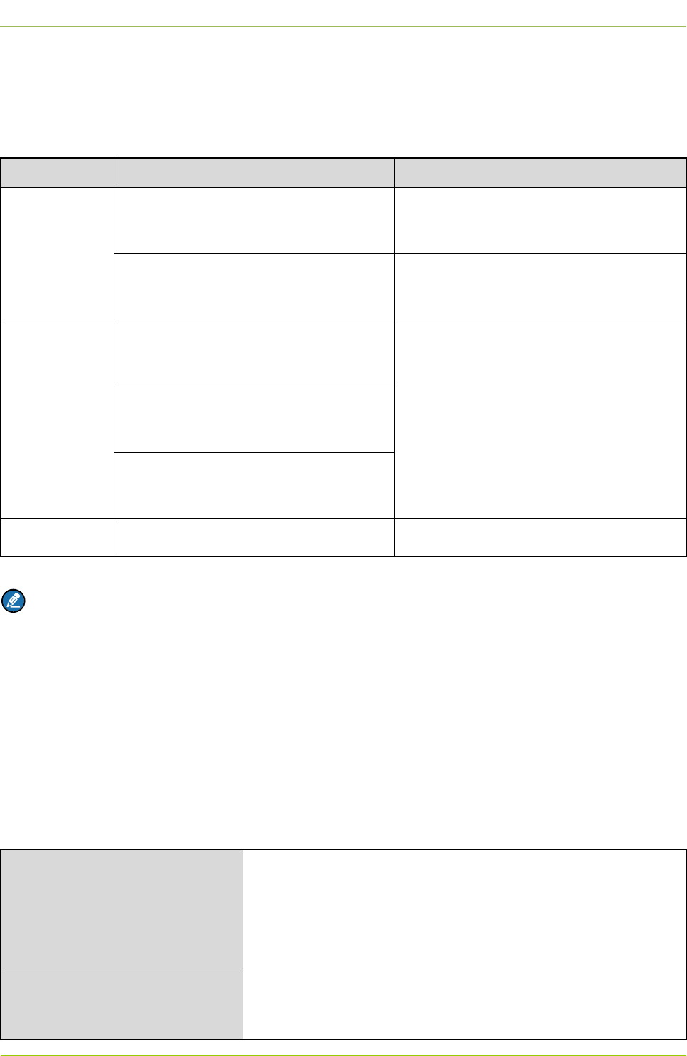
To unpack the wooden case, do as follows:
Step 1 Wear the anti-static gloves.
Step 2 Lay the wooden case on the ground with the wooden frame facing downwards. See Figure 3-1.
Hardware Installation
User Guide
32
Figure 3-1 Laying the Wooden Case
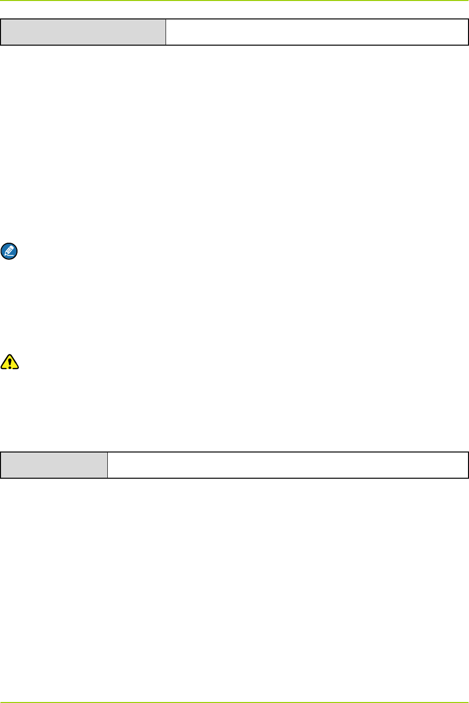
Step 3 Pull the tongue piece on the wooden cover straight using the wench, claw hammer or
screwdriver. See Figure 3-2.
Figure 3-2 Pulling the Tongue Piece Straight
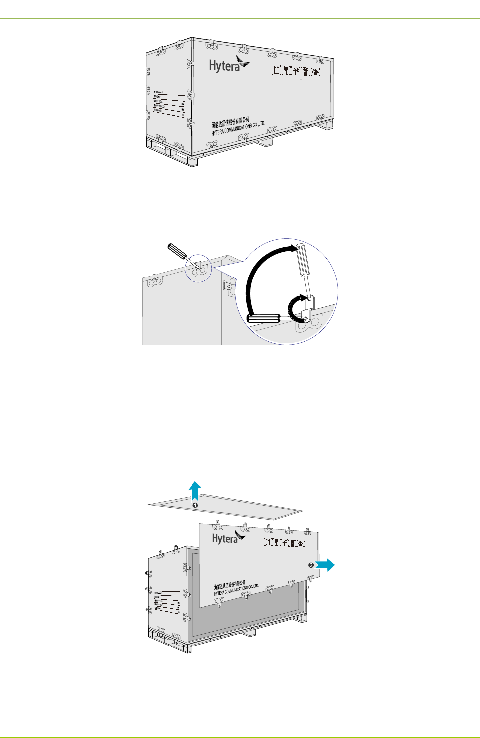
Step 4 Remove the cover (see the up arrow in Figure 3-3). If you see a cabinet, proceed to the next
step directly. If you see a carton, take it out from the wooden case and unpack as instructed in
“Unpacking the Carton” before the next step.
Step 5 Pull the tongue piece straight on the side wooden plate and remove the plate. See the right
arrow in Figure 3-3.
Figure 3-3 Removing the Wooden Cover and Side Wooden Plate
Step 6 Place the cabinet upright with the wheels facing downwards.
User Guide
Hardware Installation
33
Unpacking the Carton
Tools Paper knife
To unpack the carton, do as follows:
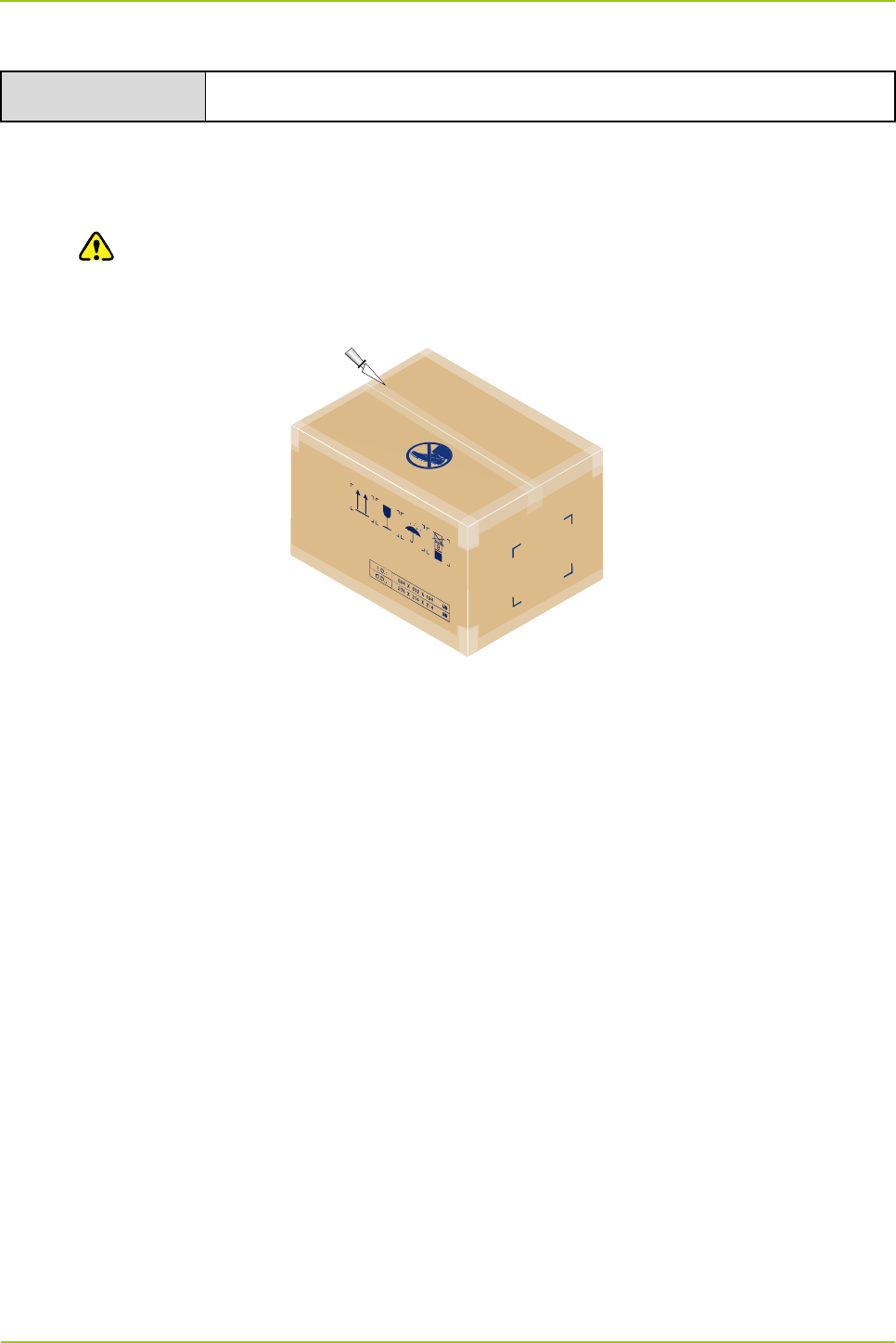
Step 1 Cut the strap along the seam of the carton cover using the paper knife. See Figure 3-4.
Caution
Apply a moderate force, to avoid damage to the internal articles.
Step 2 Open the carton and take out the articles.
Figure 3-4 Unpacking the Carton
Checking the Articles
After unpacking the wooden case and carton, carefully check the received articles according to the
Packing List.
You should perform the following check tasks:
Checking the appearance
All articles shall be free from defects such as deformation or rupture.
The cabinet shall be firm.
The characters on the articles shall be clear.
Checking the parts and accessories
The complete parts and accessories required for the hardware installation shall be contained in the
package.
Checking the internal units of the base station
Each kind of the internal unit shall comply with the Packing List in respect of the model and total
number, and shall be free from defects such as break or looseness.
After check, the project supervisor and the client have to sign the Packing List together for confirmation.
Hardware Installation
User Guide
34
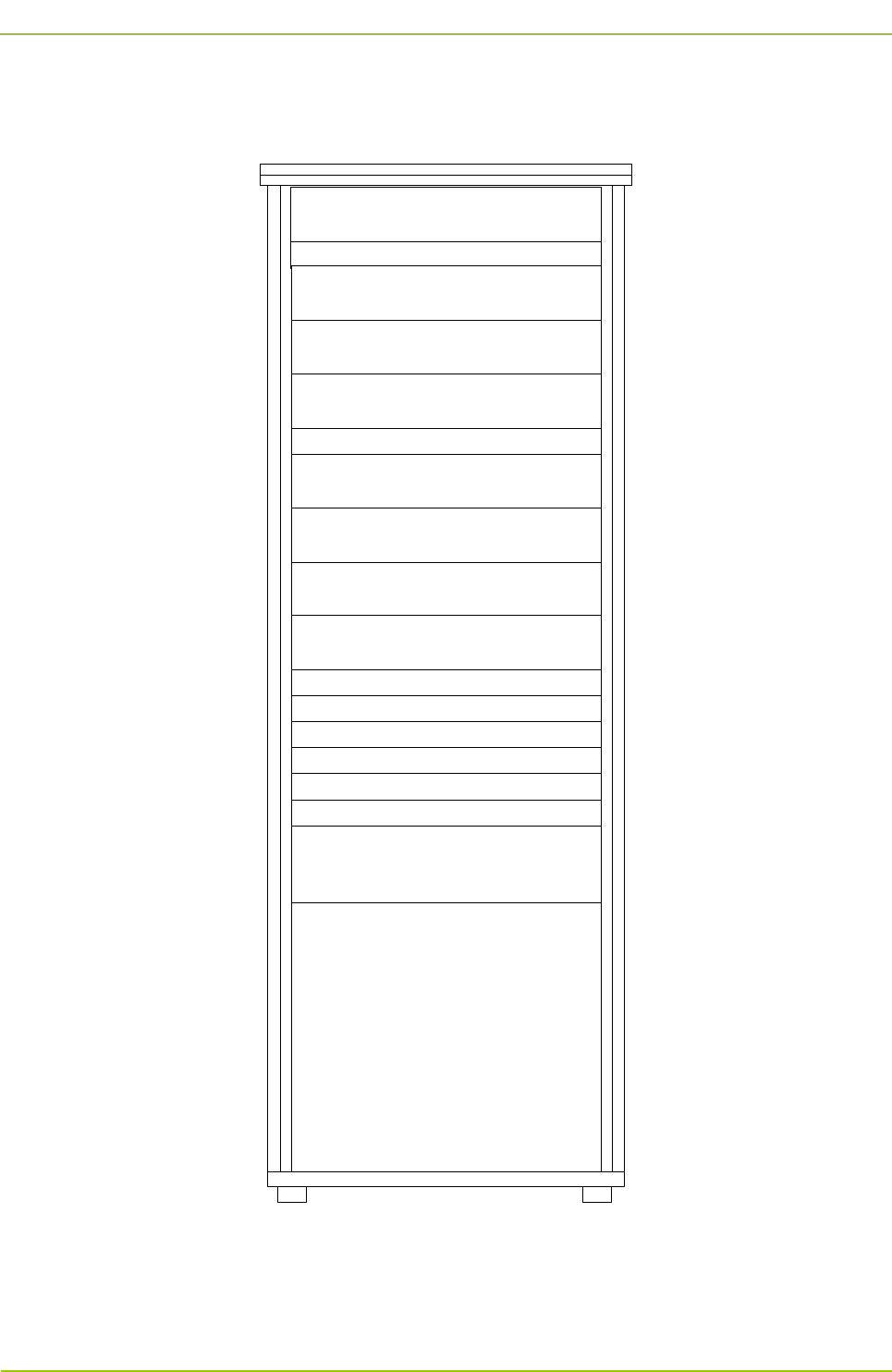
3.3 Installation Location for the Internal Unit
For the installation locations for the internal units, see Figure 3-5.
PDU
Decorative Unit
Decorative Unit
CHU
CHU Power Supply
Router
Server
DPU
CHU
Decorative Unit
CHU
CHU Power Supply
CHU
Switch
PSU
Decorative Unit
DIU
COM
Figure 3-5 Installation Locations for Internal Units of 4-Carrier Base Station
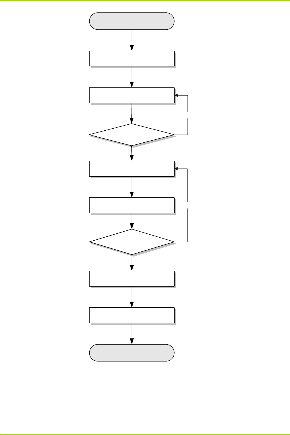
3.4 Installation Flow
For the base station installation flow, see Figure 3-6.
User Guide
Hardware Installation
35
Start
Determining a location for the
cabinet
Fixing the cabinet
Testing the
insulation performance
Pass
Installing the internal units
Connecting the cables
Checking the power
supply condition
Pass
Installing the decorative units and
side doors
Checking the installation
Complete
Fail
Fail
Figure 3-6 Installation Flow
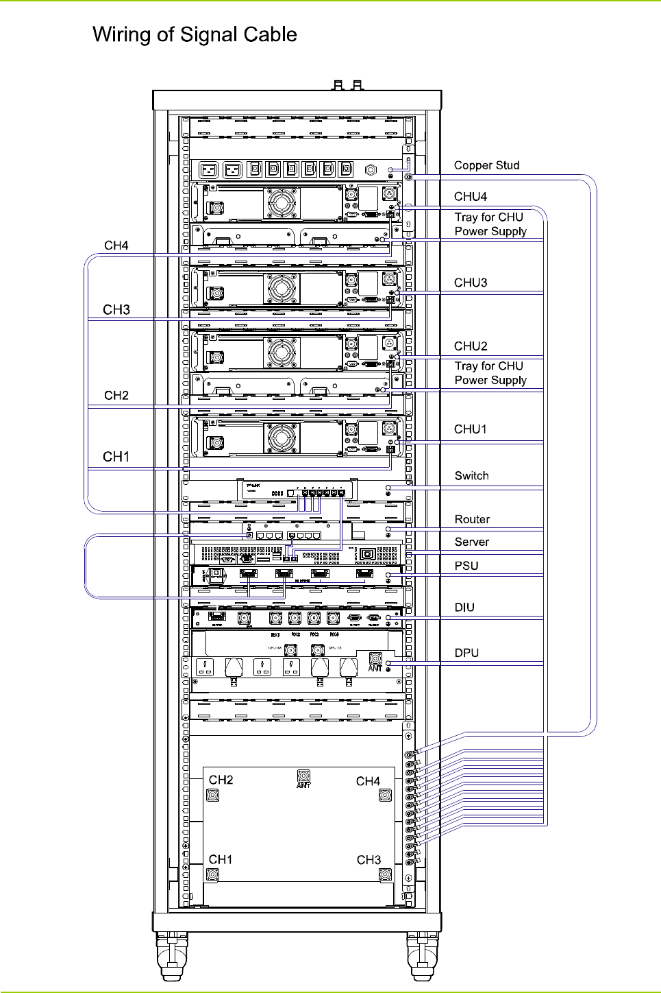
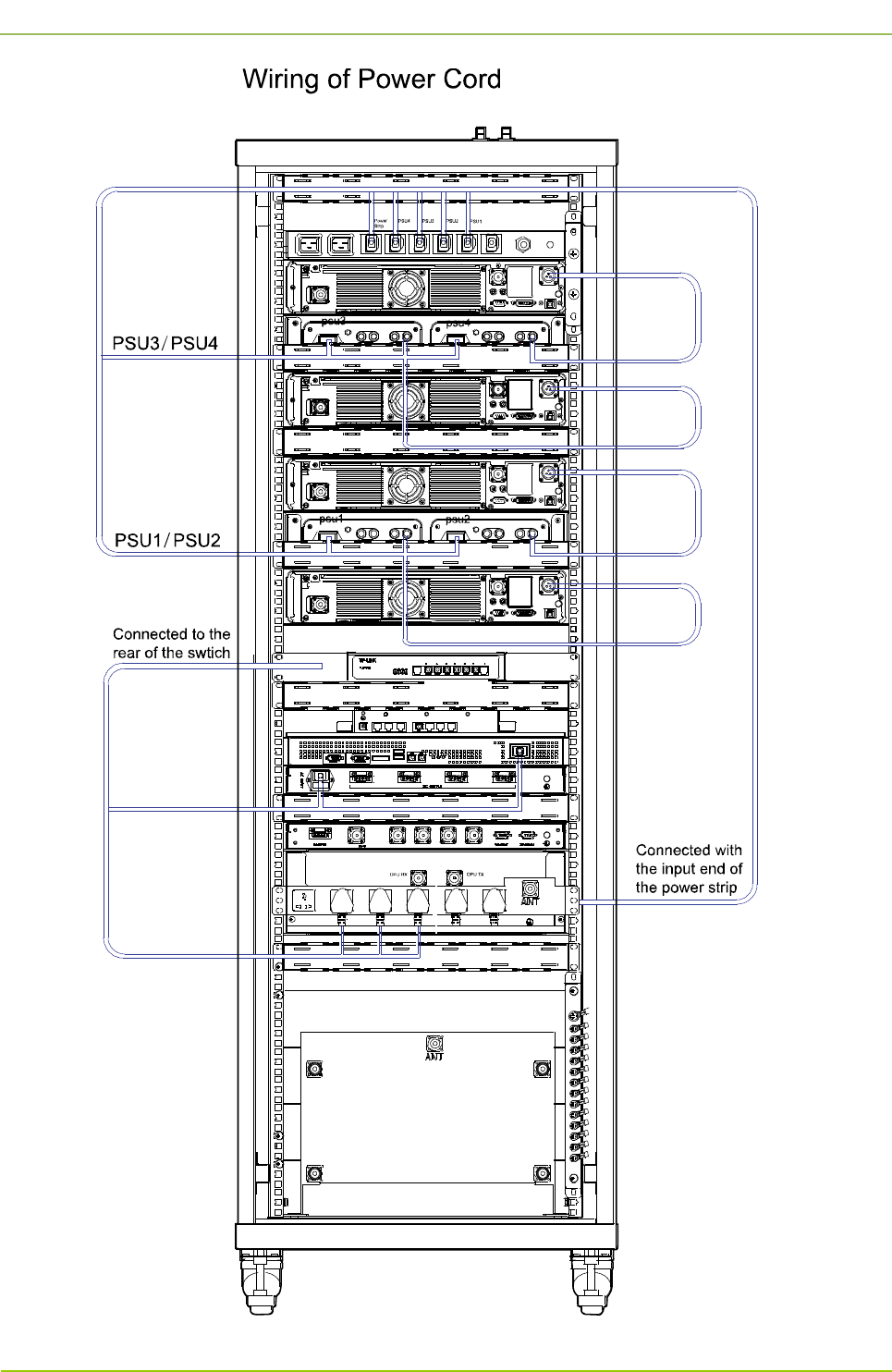
3.5 Wiring Diagram
For the wiring diagram for the base station, see Figure 3-7.
Hardware Installation
User Guide
36
User Guide
Hardware Installation
37
Hardware Installation
User Guide
38
Figure 3-7 Wiring Diagram for 4-carrier Base Station
User Guide
Hardware Installation
39
3.6 Installing the Cabinet
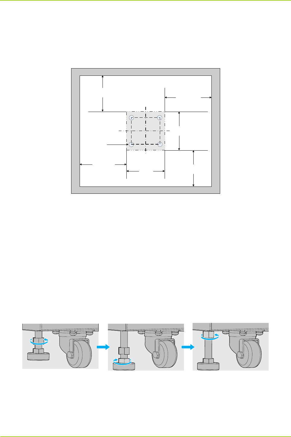
3.6.1 Determining a Location for the Cabinet
Determine a location for the cabinet as per the drawing. There shall be a clearance of at least 600mm
before the front door and back door of the cabinet. See Figure 3-8.
600mm
≥600mm
≥600mm
≥600mm
≥600mm
600mm
Wheels
Figure 3-8 Installation Location for Base Station
3.6.2 Fixing the Cabinet
To fix the cabinet, do as follows:
Step 1 Push the cabinet to the location determined above, with its front side facing properly
Step 2 Fix the cabinet by tightening the four bolts at the bottom of the cabinet. See Figure 3-9.
1. Loosen the upper nut by the wrench.
2. Loosen the lower nut by the wrench. And the cabinet will be lifted to an appropriate height
automatically.
3. Tighten the upper nut.
Figure 3-9 Fixing the Bolt
3.6.3 Testing the Insulation Performance
After the cabinet is fixed, test the insulation performance via the following steps:
Step 1 Toggle the multimeter to the “MΩ” position.
Hardware Installation
User Guide
40
Step 2 Measure the resistance between the bolt and cabinet.
Note
If the resistance is above 5MΩ, it means the cabinet is insulated properly; otherwise, check whether
an insulation part is damaged or not mounted, and fix the cabinet again for testing the insulation
performance.
3.7 Installing the Internal Units
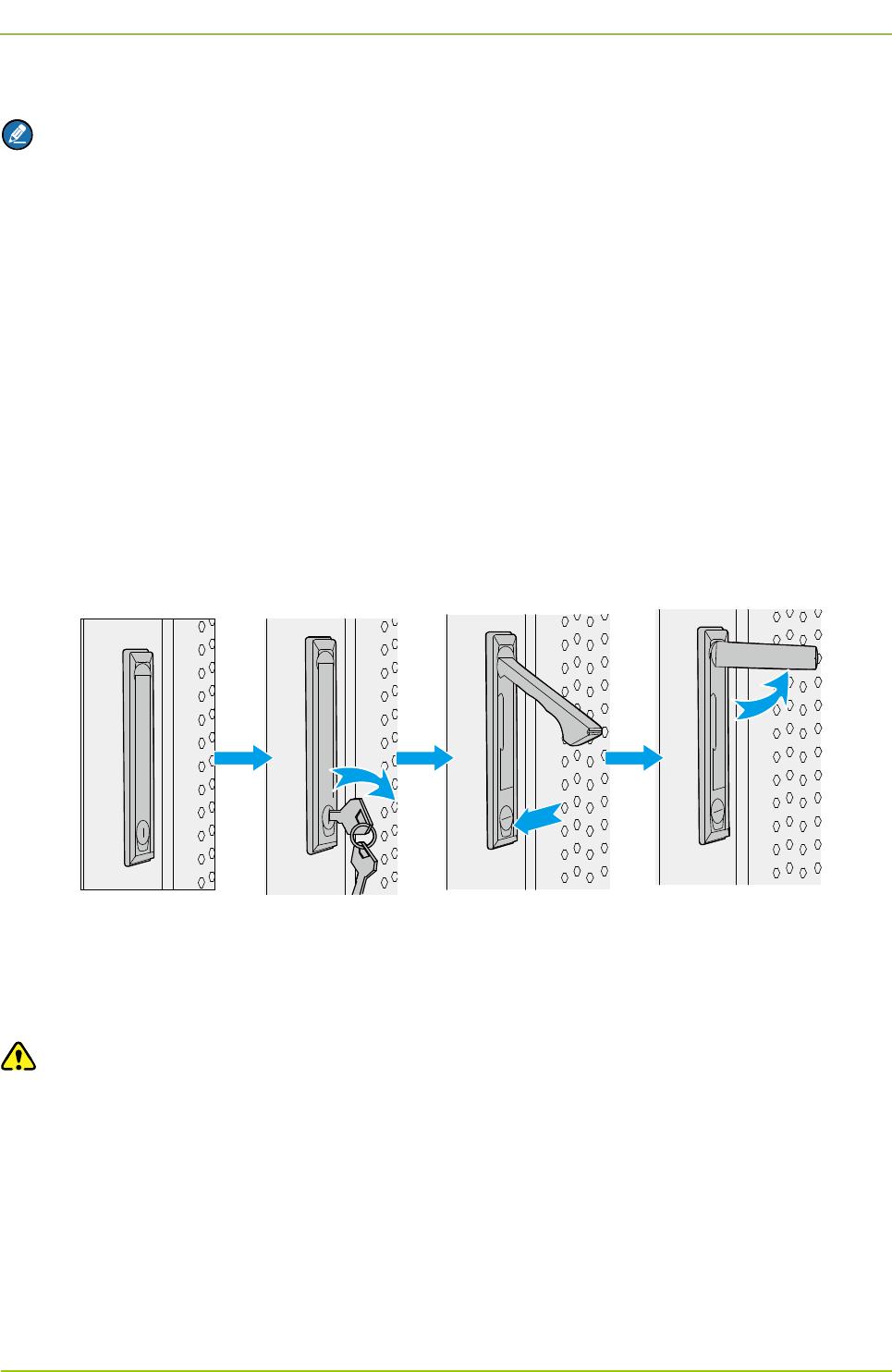
3.7.1 Opening the Front Door and Back Door
Open the front door and back door of the cabinet. See Figure 3-10.
Step 1 Unlock, and then remove the key from the keyhole in a vertical position.
Step 2 Press the PUSH button until the handle has bounced.
Step 3 Turn the handle counter-clockwise.
Step 4 Pull the handle outward and open the door.
Figure 3-10 Opening the Front Door and Back Door
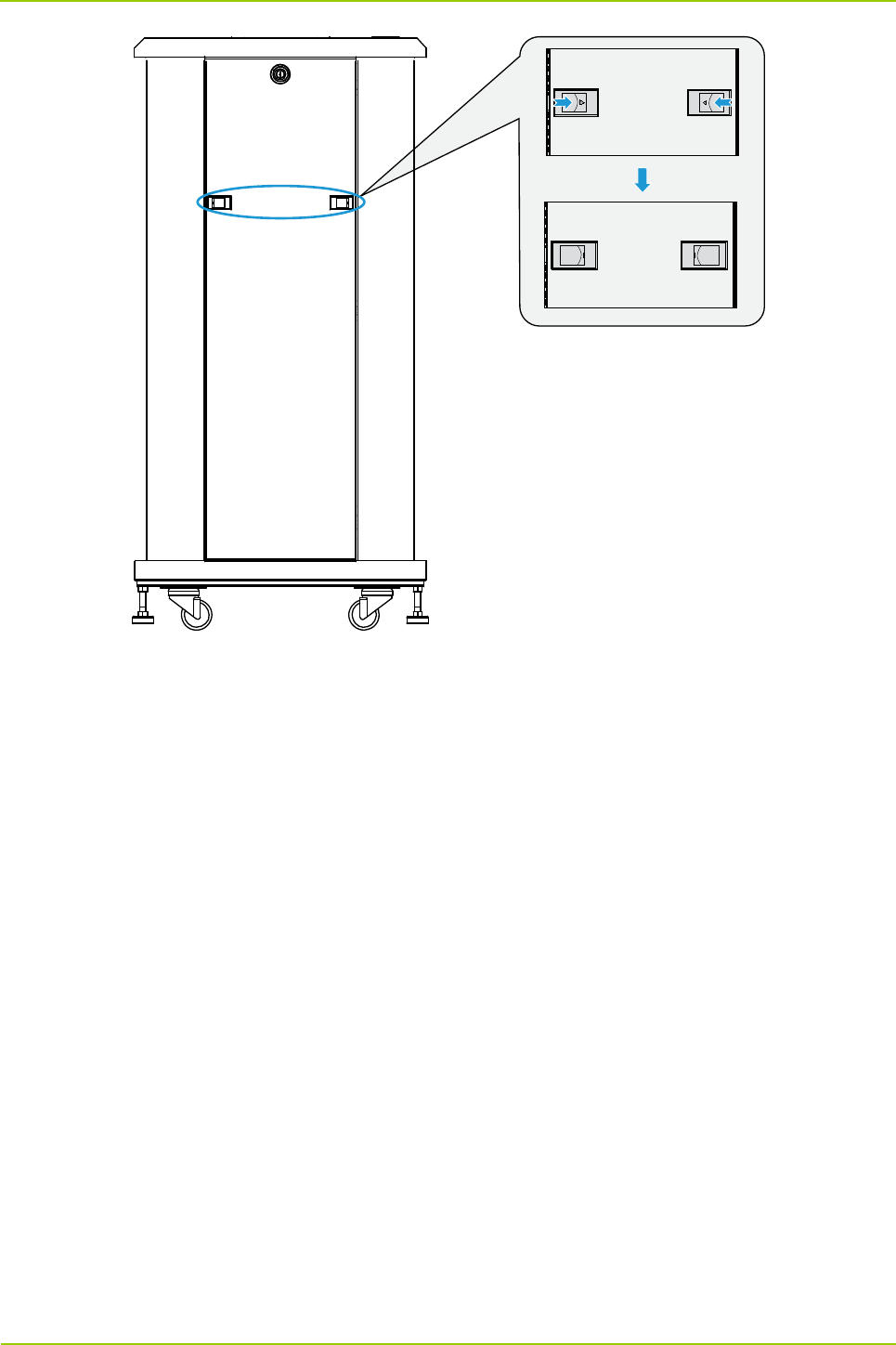
3.7.2 Removing the Side Door
Press the two latches downwards simultaneously and pull the side door outwards. See Figure 3-11.
Caution
Take care to avoid bodily injuries while removing the side door.
User Guide
Hardware Installation
41
Figure 3-11 Removing the Side Door
3.7.3 Installing the Internal Units
Installing the CHU
The PDU, CHU, CHU power supply, switch, server, DIU and DPU can be installed similarly. The
following section takes the CHU installation for example.
Step 1 Plan the installation locations for the internal units.
Plan the installation locations according to the scale on the cabinet and the height of the
internal units, and install the floating nuts properly on upright column of the cabinet to fix the
screw.
Step 2 Install the tray.
1. Place the tray at the planned location, and align its waist-shaped hole with the square hole in
the upright column.
2. Tighten the screw to secure the tray. See Figure 3-12.
Hardware Installation
User Guide
42
Figure 3-12 Installing the Tray
Note
As there are a wide variety of trays, here we only take two kinds of them for example
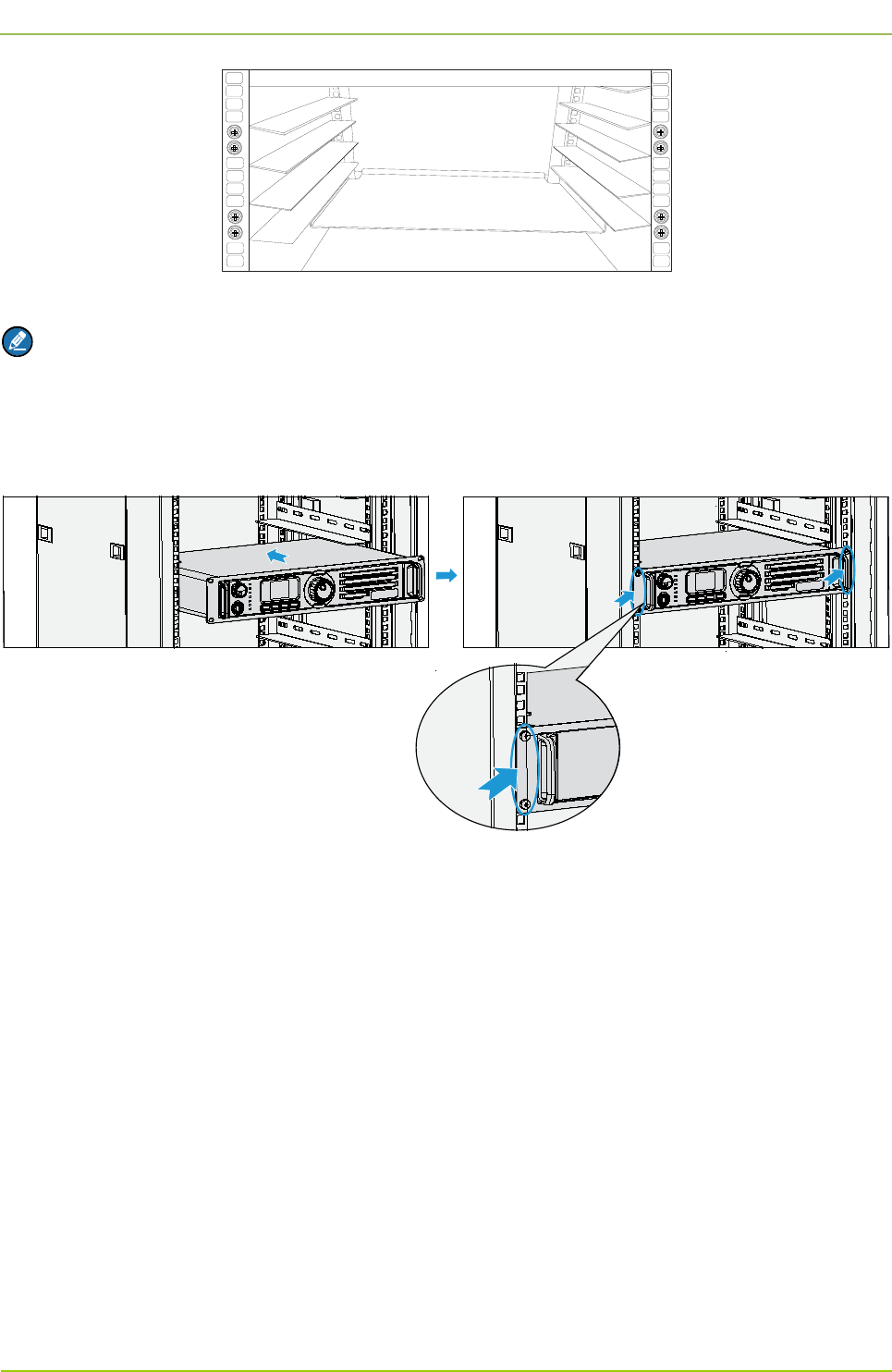
Step 3 Place the CHU on the tray, and push the tray until the waist-shaped holes on the front panel of
the MTU fit the upright column. See Figure 3-13.
Figure 3-13 Installing the CHU
Step 4 Tighten the screws on the front panel.
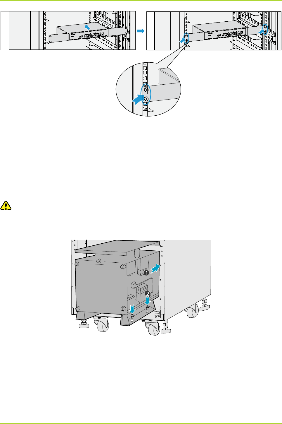
Installing the Router
The router shall be installed from the back of the cabinet. See Figure 3-14.
Step 1 Place the router in the right position, and align its ears with the square holes in the upright
column.
Step 2 Tighten the screws to secure the router.
User Guide
Hardware Installation
43
Figure 3-14 Installing the Router
Installing the COM
The COM shall be installed from the back of the cabinet. See Figure 3-15.
Step 1 Place the COM on the holder, and slide it until the screw holes in the COM are aligned with
those in the holder.
Step 2 Tighten the screws on the holder.
Caution
Take care to avoid bodily injuries while carrying the heavy COM.
Figure 3-15 Installing the COM
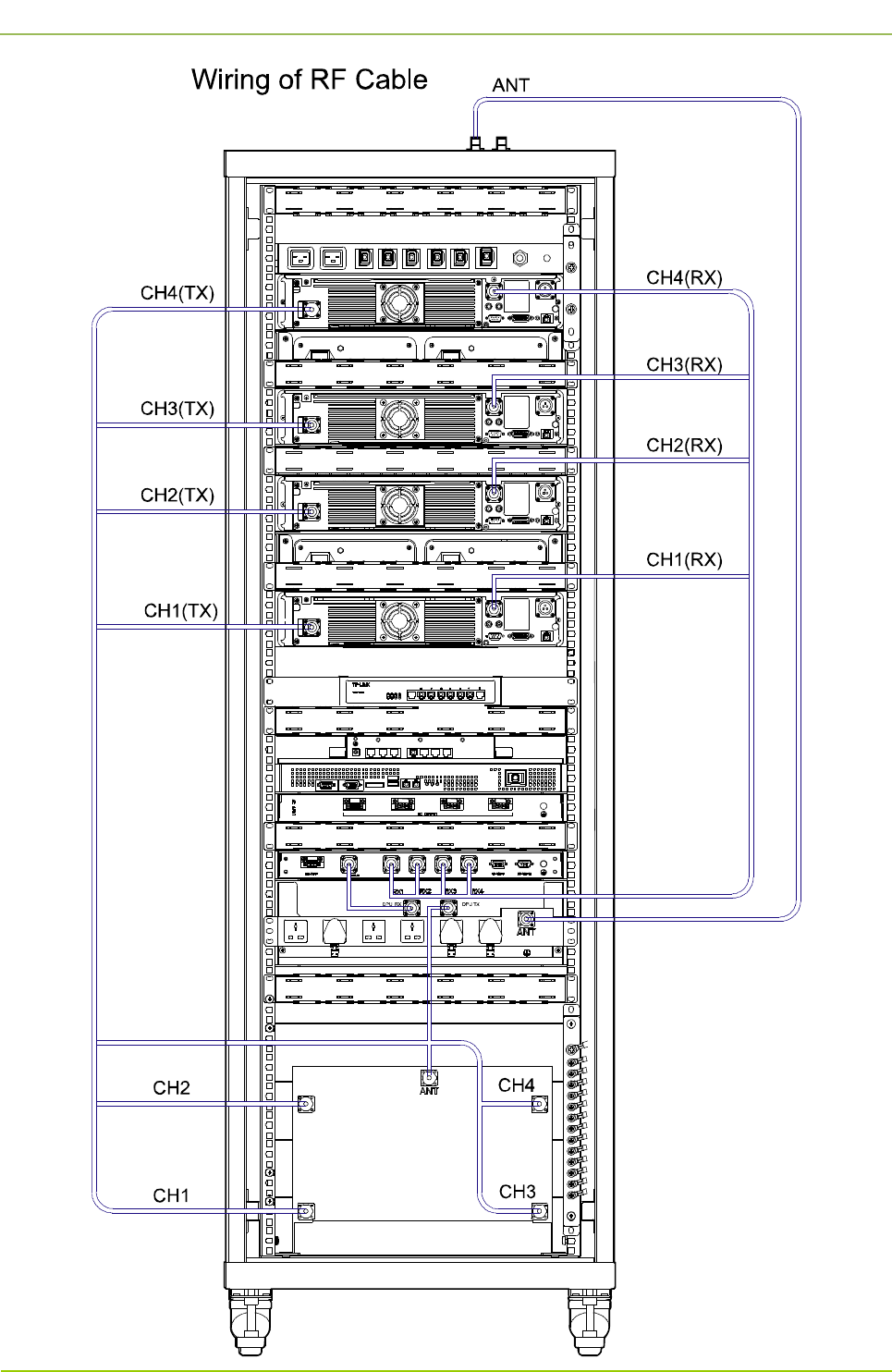
3.7.4 Connecting the Internal Cables
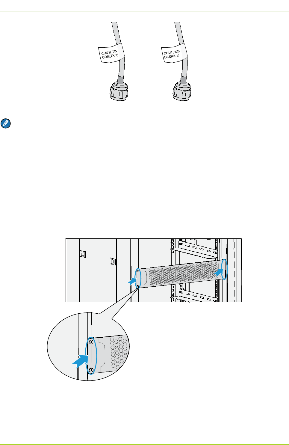
Connect the internal cables properly according to the cable location and label. See Figure 3-16.
Hardware Installation
User Guide
44
Figure 3-16 Outline of Cable
Note
In Figure 3-16, the description “CHU1(TX)-COM(TX 1)” on the label tells you that the corresponding
cable shall be connected between the TX interface of CHU1 and TX1 interface of the COM; while the
description “CHU1(RX)-DIU(RX 1) on the label tells you that the corresponding cable shall be
connected between the RX interface of CHU1 and RX1 interface of the DIU.
3.7.5 Installing the Decorative Unit
After the power supply condition is checked (see 3.9.4 Checking the Power Supply Condition), install the
decorative unit in the empty frame. See Figure 3-17.
Figure 3-17 Installing the Decorative Unit
3.7.6 Installing the Side Door
Align the side door with the cabinet, and keep pressing it until the latches have bounced.

User Guide
Hardware Installation
45
3.8 Connecting the External Cables
3.8.1 Requirements
The following requirements shall be met before connecting the external cables:
The cabinet has been installed properly.
All the internal units in the cabinet have been installed, and the On/Off Switch on all appropriate
internal units is toggled to the “Off” position.
3.8.2 Cables to Be Connected
The external cables shall be connected to the interfaces in the EIB on the top of the cabinet. For details
on the cables, see Table 3-3.
Name Color Remark
Ground Cable Yellowish green 6mm2, 49-
core, 450/750V, outer diameter:
8.1mm
AC Power Cord Red, blue, yellowish green 6mm2, 3pcs
RF Cable Black 75Ω coaxial cable, 4pcs
RJ45 Adapter Cable Grey 8-core, 100Ω twisted-pair cable, 3pcs
DB9 Adapter Cable Grey 3-core, serial cable, 1pcs
RJ48 Adapter Cable Grey 4-core, 120Ω twisted-pair cable, 1pcs
Table 3-3 Cables to Be Connected
3.9 Performing Post-installation Check
3.9.1 Requirements
The following requirements shall be met before you perform the post-installation check.
The cabinet has been installed properly.
All the internal units have been installed properly in the cabinet.
The cables have been connected properly.
All switches of the power distribution box are set to the “Off” position.
3.9.2 Checking the Cabinet
Check the cabinet according to Table 3-4.
No. Item
1 Check whether the location of the cabinet conforms to the drawing.

Hardware Installation
User Guide
46
No. Item
2 Check whether all the internal units are installed properly, and all cables in the cabinet are
connected correctly.
3 Check whether the side doors are installed and the ground cable is connected properly.
4 Check whether all screws are tightened.
5 Check whether the cabinet is stable in its place and looks tidy.
6 Check whether the surface of the cabinet is clean and well painted, and no dust or other
sundries exist in the cabinet.
7 Check whether the marks on the cabinet are correct and clear.
8 Check whether the disuse interfaces on the top of the cabinet are covered with the plastic
dust caps.
9 Check whether all parts of the cabinet are in good condition.
Table 3-4 Checklist for the Cabinet
3.9.3 Checking the Cable
Check the cables according to Table 3-5.
No. Item
1 Check whether all cables are in good condition.
2 Check whether there are no joints on all cables.
3 Check whether the ground cable is excessive. If yes, please cut the excessive part off.
4 Check whether the power cord and ground cable are connected properly.
5 Check whether the bare wire and OT handle of the terminal is sealed with the insulation
tape or heat shrinkable sleeve.
6 Check whether the power cord and ground cable are tied separately.
7 Check whether all cables are tied neatly and evenly, and whether the cable ties are facing
the same direction and cut neatly.
8 Check whether the labels on the cables are clear and neat.
Table 3-5 Checklist for the Cable
User Guide
Hardware Installation
47
3.9.4 Checking the Power Supply Condition
Caution
Before connecting the base station to the power supply, measure the resistance at all power
connectors and ground connectors using the multimeter, and check whether the short circuit exists.
Check the power supply condition via the following steps:
Step 1 Check whether the input voltage from the mains electricity satisfies the local requirements, and
whether the live wire and null wire are connected correctly.
Step 2 Toggle all power switches on the power strip to the “On” position.
Step 3 Toggle the power switch on the CHU power supply to the “On” position.
Step 4 Toggle the On/Off Switch to the “On” position.
Step 5 Toggle the power switch on the PSU to the “On” position.
Step 6 Toggle the power switch on the DIU to the “On” position.
Step 7 Check the power supply condition for the internal units according to Table 3-6.
Internal Unit LED Indication for Normal Power Supply
CHU The PWR indicator is on.
CHU Power Supply The PWR indicator is on.
Switch The PWR indicator is on.
Router The PWR indicator is on.
Table 3-6 Checklist for Power Supply Condition
Note
If an internal unit does not give the normal power supply indication, connect the base station to the
power supply again, or re-install the internal unit after disconnecting the power supply. If this problem
still exists, please contact us.
3.9.5 Checking the Environment
Check the environment according to Table 3-7.
No. Item
1 Check whether the equipment room is clean and tidy.
2 Check whether there are cable ties and sundries in the wiring rack, at the bottom of the
cabinet or around the cabinet.

Hardware Installation
User Guide
48
No. Item
3 Check whether there are cable ties and sundries on the floor of the equipment room.
Table 3-7 Checklist for Environment

User Guide
Basic Operations
49
4. Basic Operations
4.1 Powering up the Base Station
Step 1 Connect the AC power supply.
Step 2 Toggle all power switches on the power strip to the “On” position.
Step 3 Toggle the power switch on the CHU power supply to the “On” position.
Step 4 Toggle the On/Off Switch to the “On” position.
Step 5 Toggle the power switch on the PSU to the “On” position.
Step 6 Toggle the power switch on the DIU to the “On” position.
4.2 Powering off the Base Station
Step 1 Toggle the power switch on the DIU to the “Off” position.
Step 2 Toggle the power switch on the PSU to the “Off” position.
Step 3 Toggle the On/Off Switch to the “Off” position.
Step 4 Toggle the power switch on the CHU power supply to the “Off” position.
Step 5 Toggle all power switches on the power strip to the “Off” position.
Step 6 Disconnect the AC power supply.

Routine Maintenance
User Guide
50
5. Routine Maintenance
5.1 Purpose
The routine maintenance is to ensure stable and reliable operation of the device. It can help you to know
the operation status of the device, so as to detect potential troubles and remove them on time.
The routine maintenance is performed for the following specific purposes:
Remove all potential troubles to keep the system work properly.
Ensure that all performance and service specifications can meet the related requirements.
Ensure good collaboration within the entire system.
Ensure that new devices or upgraded devices can access the system properly.
5.2 Tasks
Clean the equipment room regularly.
Check the working status of the base station regularly. If an abnormal situation occurs, handle it in
time.
Clean the base station regularly.

User Guide Abbreviations
51
A Abbreviations
Abbr. Full Name
COM Combiner
DIU Divider Unit
DPU Duplexer Unit
EMI Electro Magnetic Interference
EMS Electro Magnetic Susceptibility
GPS Global Positioning System
MTBF Mean Time between Failures
OIP3 Output 3rd order Intercept Point
PDM Power Distribution Module
PDU Power Distribution Unit
PSU Power Supply Unit
VGA Video Graphics Array

52
FCC Warning:
Any Changes or modifications not expressly approved by the party responsible for compliance could
void the user's authority to operate the equipment.
This device complies with part 15 of the FCC Rules. Operation is subject to the following two
conditions: (1) This device may not cause harmful interference, and (2) this device must accept any
interference received, including interference that may cause undesired operation.
This equipment complies with FCC radiation exposure limits set forth for an uncontrolled
environment .This equipment should be installed and operated with minimum distance 2.5 m
between the radiator& your body.
Industry Canada
This device complies with Industry Canada licence-exempt RSS standard (s).
Operation is subject to the following two conditions: (1) this device may not cause
interference, and (2) this device must accept any interference, including interference
that may cause undesired operation of the device.
The term “IC:” before the certification/registration number only signifies that the
Industry Canada technical specifications were met.
Under Industry Canada regulations, this radio transmitter may only operate using an
antenna of a type and maximum (or lesser) gain approved for the transmitter by
Industry Canada. To reduce potential radio interference to other users, the antenna
type and its gain should be so chosen that, the equivalent isotropically radiated power
(e.i.r.p.) is not more than that necessary for successful communication.
User Guide Abbreviations
Le présent appareil est conforme aux CNR d'Industrie Canada applicables aux appareils radio exempts de
licence.
L'exploitation est autorisée aux deux conditions suivantes:
(1) l'appareil ne doit pas produire de brouillage, et
(2) l'utilisateur de l'appareil doit accepter tout brouillage radioélectrique subi, même si le brouillage est
susceptible d'en compromettre le fonctionnement.
Conformément à la réglementation d'Industrie Canada, le présent émetteur radio peut fonctionner avec une
antenne d'un type et d'un gain maximal (ou inférieur) approuvé pour l'émetteur par Industrie Canada. Dans
le but de réduire les risques de brouillage radioélectrique à l'intention des autres utilisateurs, il faut choisir
le type d'antenne et son gain de sorte que la puissance isotrope rayonnée équivalente (p.i.r.e.) ne dépasse
pas l'intensité nécessaire à l'établissement d'une communication satisfaisante.

45
User Guide Abbreviations
This product meets the applicable Industry Canada technical specifications.
This Class A digital apparatus complies with Canadian ICES-003.
IC Radiation Exposure Statement:
This equipment complies with IC RF radiation exposure limits set forth for an
uncontrolled environment. This transmitter must not be co-located or operating in
conjunction with any other antenna or transmitter.
This equipment should be installed and operated with minimum distance 2.5m
between the radiator & your body.
Le present matériel est conforme aux specifications techniques applicables d’Industrie Canada.