Hytera Communications DS-6250U1 DMR Trunking Base Station User Manual
Hytera Communications Corporation Limited DMR Trunking Base Station
User Manual
DS-6250 U1 DMR Trunking Base Station
User Guide
Document Version: V1.0
Release Date: July 2017
Copyright Information
Hytera is the trademark or registered trademark of Hytera Communications Corporation Limited (the
Company) in People's Republic of China (PRC) and/or other countries or areas. The Company retains the
ownership of its trademarks and product names. All other trademarks and/or product names that may be
used in this manual are properties of their respective owners.
The product described in this manual may include the Company's computer programs stored in memory or
other media. Laws in PRC and/or other countries or areas protect the exclusive rights of the Company with
respect to its computer programs. The purchase of this product shall not be deemed to grant, either directly
or by implication, any rights to the purchaser regarding the Company's computer programs. The
Company's computer programs may not be copied, modified, distributed, decompiled, or
reverse-engineered in any manner without the prior written consent of the Company.
Disclaimer
The Company endeavors to achieve the accuracy and completeness of this manual, but no warranty of
accuracy or reliability is given. All the specifications and designs are subject to change without notice due
to continuous technological development. No part of this manual may be copied, modified, translated, or
distributed in any manner without the prior written consent of the Company.
We do not guarantee, for any particular purpose, the accuracy, validity, timeliness, legitimacy or
completeness of the third-party products and contents involved in this manual.
If you have any suggestions or would like to receive more information, please visit our website at:
http://www.hytera.com.

User Manual Contents
i
Contents
Documentation Information ..................................................................................................................... 1
1. Introduction ........................................................................................................................................... 2
2. Getting Started ...................................................................................................................................... 5
2.1 Appearance ....................................................................................................................................... 5
2.2 Connectors and Interfaces ................................................................................................................. 6
3. Installation ............................................................................................................................................. 8
3.1 Safety Information .............................................................................................................................. 8
3.2 Installation Flow ................................................................................................................................. 9
3.3 Installation Requirements .................................................................................................................. 9
3.3.1 Site Requirements ................................................................................................................... 9
3.3.2 Tools ...................................................................................................................................... 10
3.3.3 Materials ................................................................................................................................. 11
3.4 Product Installation .......................................................................................................................... 11
3.4.1 Knowing Installation Parts ...................................................................................................... 11
3.4.2 Installing iBS ........................................................................................................................... 11
3.4.3 Laying out Cables .................................................................................................................. 16
4. Turning On/Off iBS .............................................................................................................................. 20
4.1 Turning On iBS ................................................................................................................................ 20
4.2 Turning Off iBS ................................................................................................................................ 20
5. Care and Cleaning ............................................................................................................................... 21
6. Specifications ...................................................................................................................................... 22
User Manual Documentation Information
1
Documentation Information
This section describes conventions, and revision history of this document.
Audience
This document is intended to be read by:
Technical support engineers
Maintenance engineers
Installation and commissioning engineers
Enterprise users
Documentation Conventions
Icon Conventions
Icon Description
Tip Indicates information that can help you make better use of your product.
Note Indicates references that can further describe the related topics.
Caution Indicates situations that could cause data loss or equipment damage.
Warning Indicates situations that could cause minor personal injury.
Danger Indicates situations that could cause major personal injury or even death.
Notation Conventions
Item Description
“ ”
The quotation marks enclose the name of a software interface element. For
example, click “OK”.
Bold The text in boldface denotes the name of a hardware button. For example, press
the PTT key.
->
The symbol directs you to access a multi-level menu. For example, to select “New”
from the “File” menu, we will describe it as follows: “File -> New”.

Documentation Information User Manual
2
Revision History
Document Version Product Version Release Date Description
00 V1.0 August 2017 Release date.
FCC Warning
Any Changes or modifications not expressly approved by the party responsible for compliance could void the
user’s authority to operate the equipment.
This device complies with part 15 of the FCC Rules. Operation is subject to the following two conditions: (1)
This device may not cause harmful interference, and (2) this device must accept any interference received,
including interference that may cause undesired operation.
FCC Radiation Exposure Statement:
This equipment complies with FCC radiation exposure limits set forth for an controlled environment. This
equipment should be installed and operated with minimum distance 140cm between the radiator& your body.
This transmitter must not be co-located or operating in conjunction with any other antenna or transmitter.
Note: This equipment has been tested and found to comply with the limits for a Class B digital device, pursuant
to part 15 of the FCC Rules. These limits are designed to provide reasonable protection against harmful
interference in a residential installation. This equipment generates uses and can radiate radio frequency energy
and, if not installed and used in accordance with the instructions, may cause harmful interference to radio
communications. However, there is no guarantee that interference will not occur in a particular installation. If
this equipment does cause harmful interference to radio or television reception, which can be determined by
turning the equipment off and on, the user is encouraged to try to correct the interference by one or more of the
following measures:
—Reorient or relocate the receiving antenna.
—Increase the separation between the equipment and receiver.
—Connect the equipment into an outlet on a circuit different from that to which the receiver is connected.
—Consult the dealer or an experienced radio/TV technician for help.
ISEDC RSS warning
This device complies with Innovation, Science and Economic Development Canada Compliance
licence-exempt RSS standard (s). Operation is subject to the following two conditions: (1) this device may not
cause interference, and (2) this device must accept any interference,including interference that may cause
undesired operation of the device.
Le présent appareil est conforme aux CNR d'Innovation, Sciences et Développement économique Canada
User Manual Introduction
3
applicables aux appareils radio exempts de licence.
L'exploitation est autorisée aux deux conditions suivantes:
(1) l'appareil ne doit pas produire de brouillage, et
(2) l'utilisateur de l'appareil doit accepter tout brouillage radioélectrique subi, même si le brouillage est
susceptible d'en compromettre le fonctionnement.
ISEDC Radiation Exposure Statement:
This equipment complies with ISEDC RF radiation exposure limits set forth for an controlled environment. This
transmitter must not be co-located or operating in conjunction with any other antenna or transmitter.
This equipment should be installed and operated with minimum distance 140cm between the radiator & your
body.
IC exposition aux radiations:
Cet équipement est conforme avec ISEDC les limites d'exposition aux rayonnements définies pour contrôlé
environnement.
Cet émetteur ne doit pas être co-localisés ou fonctionner en conjonction avec une autre antenne ou émetteur.
Cet équipement doit être installé et utilisé avec un minimum de 140cm de distance entre le radiateur et votre
corps.
Restrict use warning:

Introduction User Manual
4
1. Introduction
Integrated base station (iBS) is a new generation of base station supporting both narrow-band and
wide-band communications. It integrates multiple functionalities performed by separate hardware units
such as CHU, BSCU, DPU, and IRU into one hardware unit. iBS delivers stable signal coverage for a
certain area and ensures smooth and continuous communication. It is suitable for users from public sector
such as police, firemen, as well as commercial users.
Highlights
Small footprint, low power consumption, and excellent mobility.
Fan-less design achieved by high-grade heat conductive materials.
Easy installation, low construction and maintenance cost.
Multi-carrier technology and SDR technology, supports up to eight carriers.
User Manual Getting Started
5
2. Getting Started
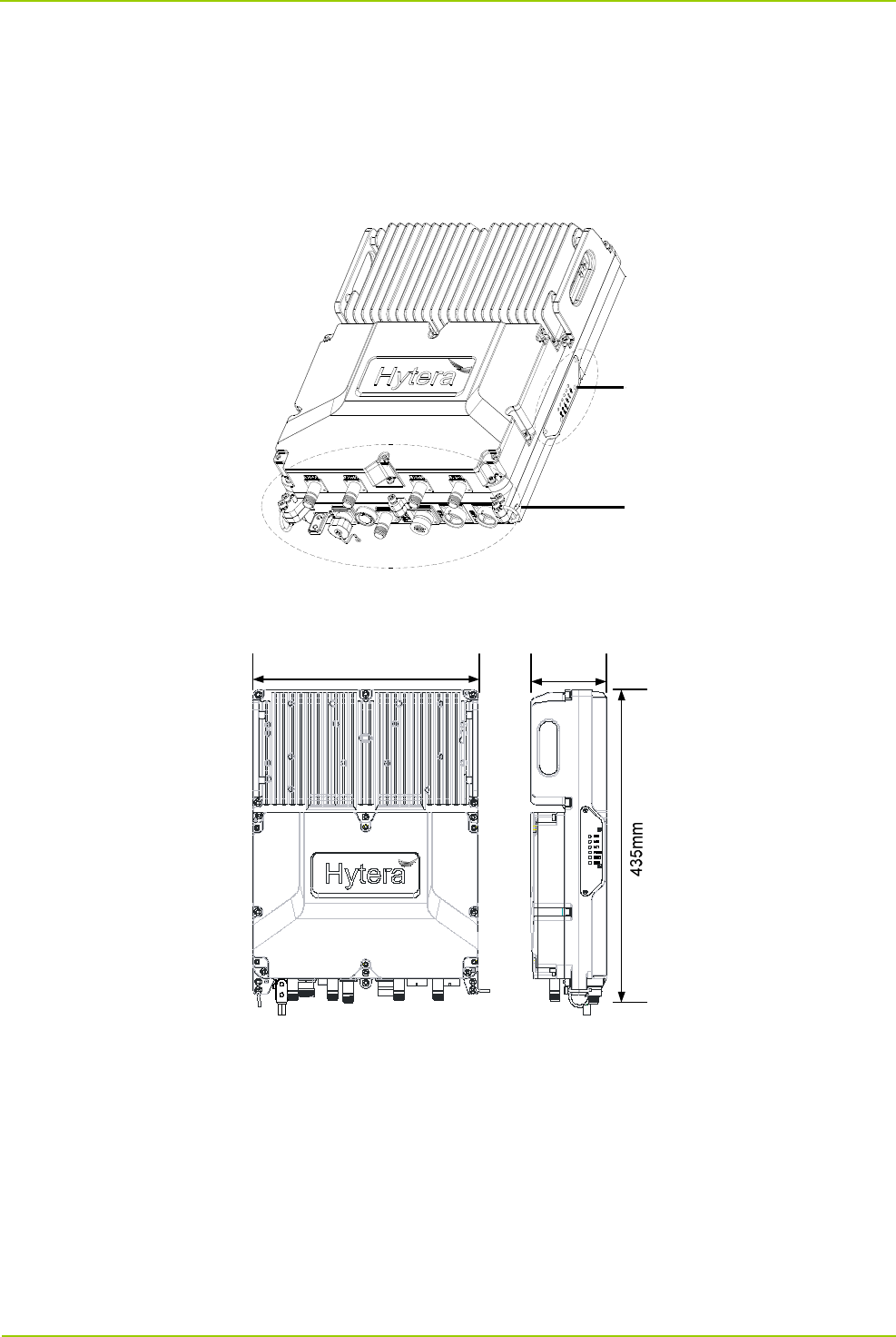
2.1 Appearance
The figure below shows the overall appearance of iBS.
The figure below shows dimensions of iBS.
340mm 157.5mm
Indicator
Connector
Connected to GNSS antenna.
Getting Started User Manual
6
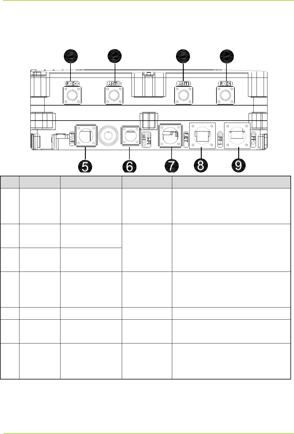
2.2 Connectors and Interfaces
The figure below shows connectors and interfaces located on the bottom of the iBS.
No. Mark Name Specification Description
1 RXD0
Antenna diversity
reception connector
0
N-F
Connected to diversity reception antenna
for receiving diversity RF signals.
2 ANT0
Antenna connector
0
N-F
Connected to antenna for transmitting
and receiving RF signals.
3
ANT1 Antenna connector
1
4 RXD1
Antenna diversity
reception conenctor
1
N-F
Connected to diversity reception antenna
for receiving diversity RF signals.
5 PWR Power supply / Connected to external power supply.
6 WI-FI/GNSS
GNSS
antenna connector
N-F (GNSS)
7 RET
External monitoring
interface
DB8
Connected to external monitoring device,
supports dry contact signal input X 3 and
RS422 signal input X 1.
1234

User Manual Getting Started
7
No. Mark Name Specification Description
8 SFP1
Transmission
interface 1
SFP/SFP-F
Connected to external transmission
network.
Connected to optical-electric
conversion module, supports Gigabit
Ethernet.
Supports SFP module.
Supports single-mode optical fiber
(communication distance≤10km) and
multi-mode optical fiber
(communication distance≤200km).
9 SFP0
Transmission
interface 0

Installation User Manual
8
3. Installation
3.1 Safety Information
Before performing any operation, read the following precautions and operation instructions carefully to
ward off potential risks.
Local Laws and Regulations
When operating a device, comply with the local safety laws and regulations.
Power Supply
Danger
Direct contact or indirect contact (through moist objects) with the high voltage or mains
electricity may result in fatal danger.
Non-standard and incorrect operations on the high-voltage power supply may result in fire and
electric shock.
Never wear conductive articles such as watches, bracelets or rings during operation.
Do use dedicated tools during high voltage or AC operations.
Take necessary measures to prevent entry of moisture into the equipment operating under a moist
environment.
Make sure the lightning-proof grounding is implemented for the equipment to prevent it from being
damaged by lightning strikes.
Disconnect the equipment from the power supply before installing or uninstalling it.
Check the label on the cable to ensure correct connection.
Make sure that the equipment is well grounded before powering it on.
Disconnect the equipment from the power supply if you find water or other liquids in the equipment.
Make sure the power switch is toggled to the “Off” position before installing the equipment.
Working at Heights
Work performed 2 m (6.56 ft.) above the ground is regarded as work at heights. Work at heights, comply
with related local regulations.
Stop such work in any of the following conditions: adverse weather, wet steel tubes, and other risky
situations.
Set danger signs and prevent unauthorized person from entering the work area.
Avoid stacking scaffolds and other materials, and staying or passing below the aerial work platform.
User Manual Installation
9
Avoid dropping machinery and tools that may cause injury.
Take sound safety actions such as wearing the hamlet and safety belt properly.
Do wear heat-retaining clothes when working in cold areas.
Make sure that the ladder is safe for use, and overload is strictly prohibited.
The slant of the ladder is suggested to be 75°. When using a ladder, place it on a stable ground, and
take protective measures on the base part of the ladder for skid resistance.
Handle and use all instruments and tools with care to avoid falling.
Do not play or sleep on the aerial work platform.
Personnel
Installation and maintenance personnel must be trained to perform operations correctly and safely.
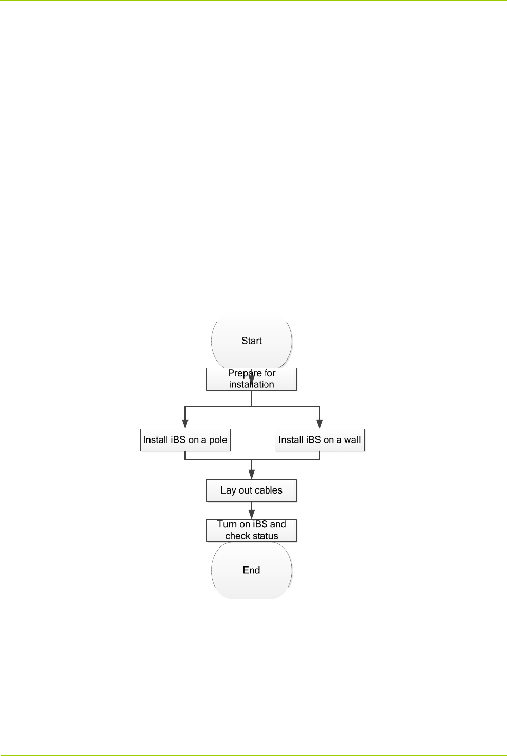
3.2 Installation Flow
The figure below shows the flow of installing iBS.
3.3 Installation Requirements
3.3.1 Site Requirements
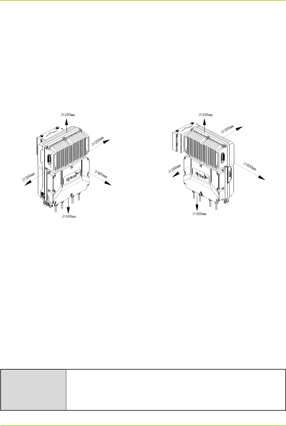
Space Requirements
It is recommended that the space of at least 200 mm be left between the product top and the ceiling.
Installation User Manual
10
It is recommended that the space of at least 500 mm be left between the product bottom and the
ground.
For product installed at its back, the space of at least 200 mm should be left at both left and right sides;
for product installed at its left side, the space of at least 200 mm should be left in front and at back of
product.
For product installed at its back, the space of at least 800 mm should be left in front of product; for
product installed at its left side, the space of at least 800 mm should be left at its right side.
Install the product upright at a proper position.
Earthing Requirements
When installing the equipment, ground the equipment before any operations and remove the ground
cable only after you remove all the other components and cables from the equipment.
Ensure that the ground conductor is intact.
Do not operate the equipment in the absence of a suitably installed ground conductor.
The equipment must be connected to the PGND permanently. Before operating the equipment, check
the electrical connections of the equipment and ensure that the equipment is properly grounded.
3.3.2 Tools
Prepare the following tools for installation.
Regular Tool
Philips driver, flat blade screwdriver, adjustable wrench, Allen wrench,
cross-type torque screwdriver, combination wrench, rubber hammer, and torque
wrench.
Back Installation Side Installation
User Manual Installation
11
Safety Tool Antistatic wrist strap, safety belt, helmet, safety rope, and slip-proof gloves.
Cable Making Tool Wire stripper, wire crimper, and wire cutter.
Measuring Tool Multimeter, tape measure, level.
Auxiliary Tool Fixed pulley, step ladder, marker pen, percussion drill, electrical tape, anti-UV
cable tie, label, screw kit, expansion screw, utility knife, heat gun, and duct tape.
3.3.3 Materials
Before installation, check that all materials are well received.
3.4 Product Installation
The iBS can be mounted on a pole or wall as per needs.
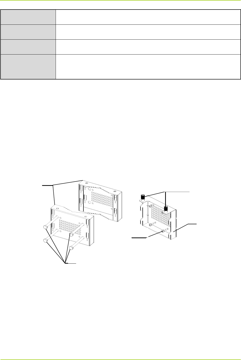
3.4.1 Knowing Installation Parts
The following figure shows parts needed for iBS installation.
3.4.2 Installing iBS
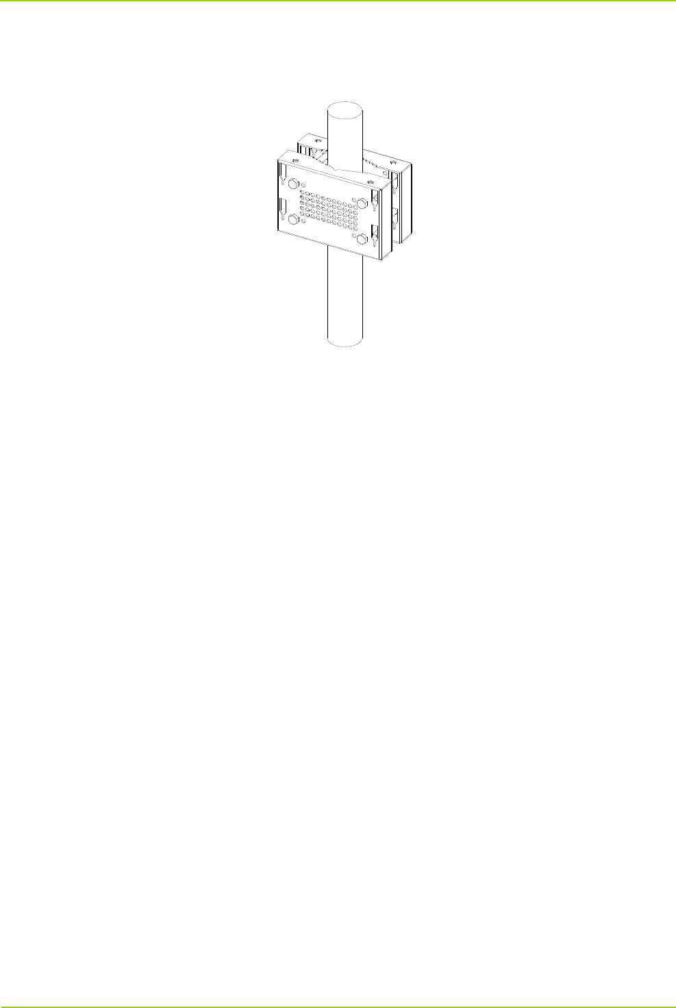
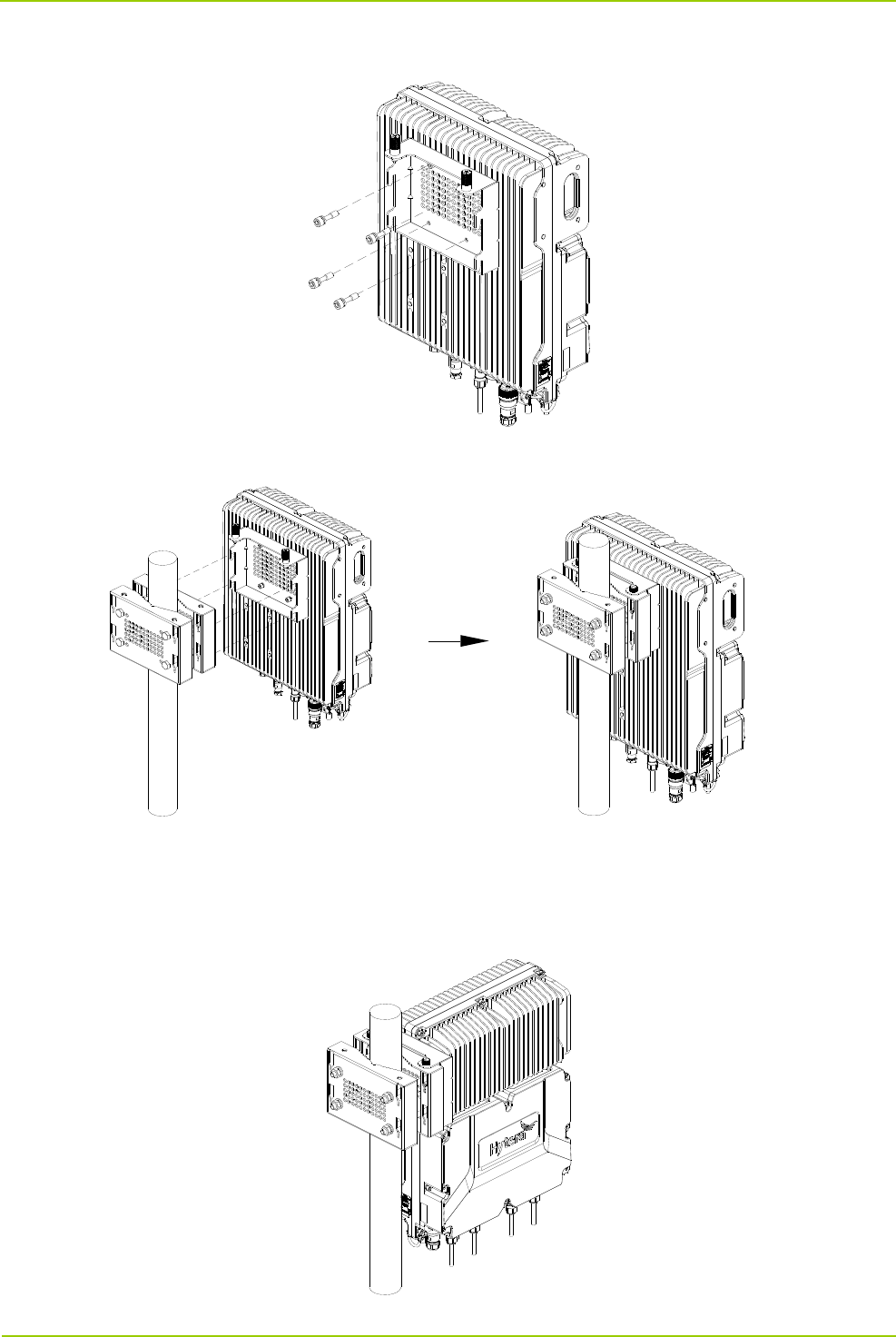
3.4.2.1 Installing iBS on a Pole
You can install iBS on a metal at the back or left side of iBS.
Installing iBS at Back
1. Mark the installation position of the auxiliary fixture on the pole by using a marking pen.
AuxiliaryFixture
CaptiveScrew
BackPanel
M6Screw
Bolt
Installation User Manual
12
2. Place the auxiliary fixture onto the pole, insert four bolts into the auxiliary fixture and then tighten four
nuts by using a torque wrench.
User Manual Installation
13
3. Secure the back panel onto the back of the iBS using four M6 screws.
4. Insert the back panel into the auxiliary fixture and tighten the captive fasteners on the back panel of iBS.
Installing iBS at Left Side
Installing iBS at left side and installing iBS at back are almost the same. The only difference is that the back
panel is secured to the left side rather than back of the iBS.
Installation User Manual
14
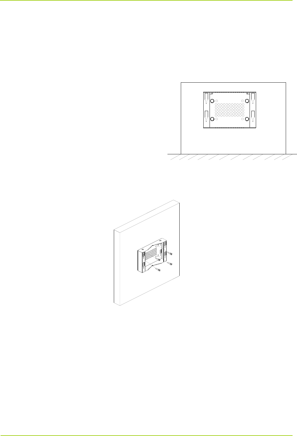
3.4.2.2 Installing iBS on a Wall
You can install iBS on a wall at the back or left side of iBS.
Installing iBS at Back
1. Place the auxiliary fixture on the wall at the installation position and then mark the anchor points by
using a marking pen.
2. Drill holes at the anchor points and then install the expansion bolt assemblies.
3. Fit the auxiliary fixture on the expansion bolts, and then tighten the bolts.
4. Secure the back panel onto the back of the iBS using four M6 screws.
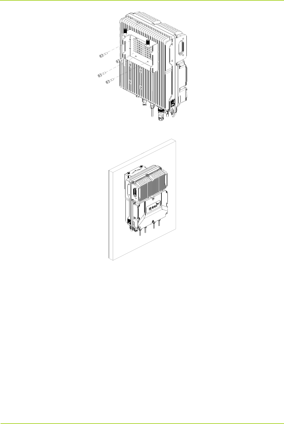
User Manual Installation
15
5. Insert the back panel into the auxiliary fixture and tighten the captive fasteners on the back panel of iBS.
Installing iBS at Left Side
Installing iBS at left side and installing iBS at back are almost the same. The only difference is that the back
panel is secured to the left side rather than back of the iBS.

Installation User Manual
16
3.4.3 Laying out Cables
3.4.3.1 General Requirements
Lay out cables according to requirements to reduce interference between them.
Safety Requirements
Lay out cables away from sharp objects or jagged walls, or protect cables using conduit.
Lay out cables away from heat sources, or add heat-insulation materials between cables and heat
sources.
Requirements for binding cables
Bind same cables together.
Bind cables securely and neatly, without damaging the cable jackets.
Ensure that cable ties face the same direction and are aligned in rows horizontally.
After installing cables, attach labels or tags to the two ends of each cable.
Cables of different types cannot be crossed.
Requirements for laying out power cables
The routing of power cables must meet engineering design drawing requirements.
If the power cable length is insufficient, replace the power cable. The power cable must be complete
and cannot have splices or welding points.
Avoid knotting or twisting the cable.
Requirements for laying out ground cables
The ground cable cannot be led in aerially, but buried in the earth or arranged indoor.

GNSS Antenna N-M GNSS interface GNSS SPD
User Manual Installation
17
Ground cables must be separated from signal cables to reduce interference between them.
All metal components in the shell must be securely connected to the ground cable.
Requirements for laying out optical fibers
Do not bind optical fibers where they are bent.
Do not press optical fibers forcibly or crush optical fibers with force. Leave sharp objects away from
optical fibers to prevent damage to optical fibers.
Coil up redundant optical fibers round specialize devices such as the splice tray.
Coil optical fibers gently and do not break them.
Cover optical fiber connectors with protective caps.
3.4.3.2 Cable Connection Description
The following table describes the connection of respective cables.
Cable One end (at iBS) Other end
Connector Connected to …… Connected to ……
Ground Cable Ring terminal Ground terminal Grounding bar
RF Antenna N-M RXD0/RXD1/ANT0/ANT1
interface
Antenna system
Power Cable Round electric
connector
PWR interface External power supply
Optical Fiber SFP/SFP+ SFP0/SFP1 interface External transmission device
(such as switch, router)
Monitoring
Cable
8-pin aviation
connector
RET interface External monitoring device
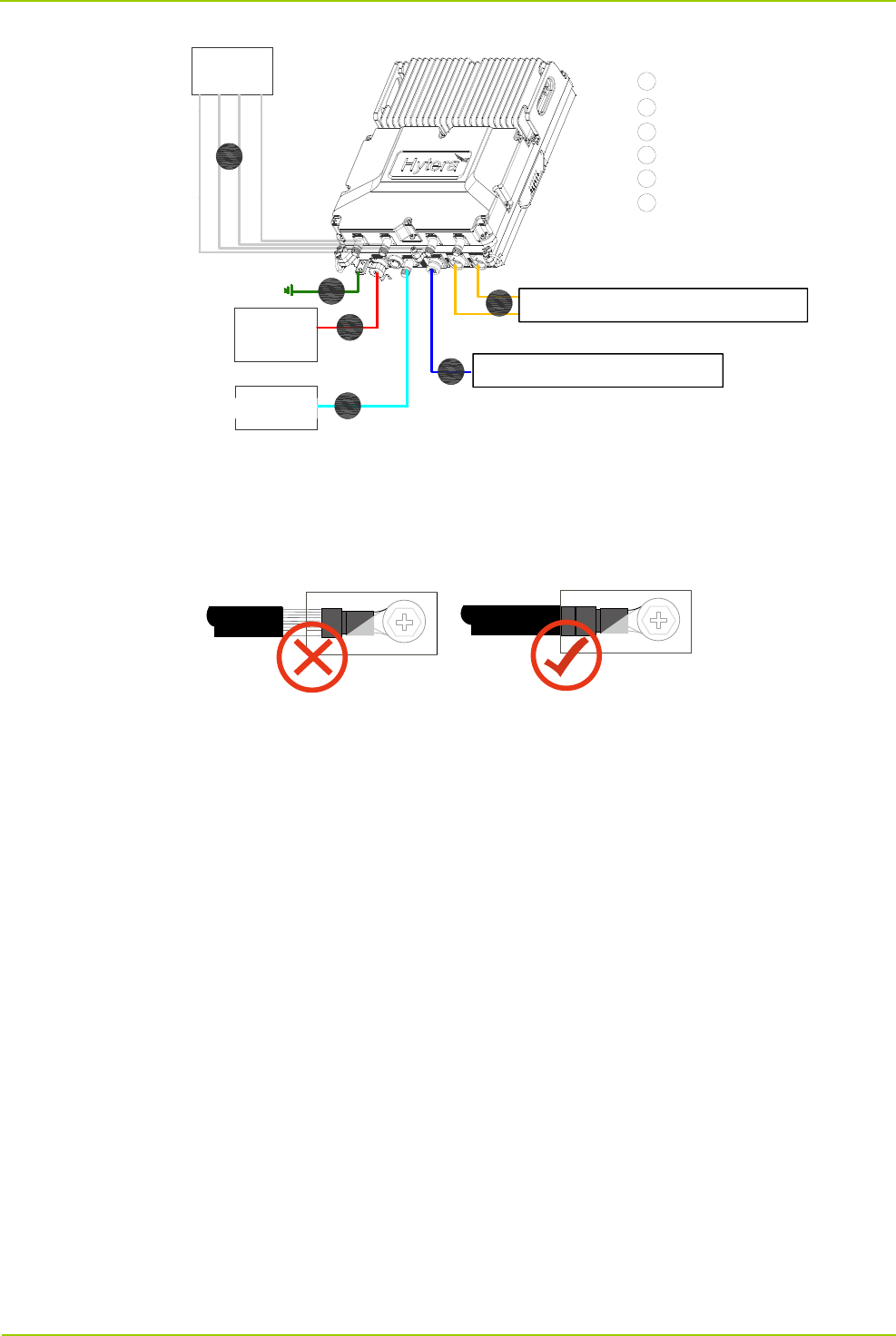
3.4.3.3 Wiring Diagram
The following figure shows wiring diagram of iBS.
Installation User Manual
18
3.4.3.4 Installing Ground Cable
1. Make a ground cable having ring terminals with shrink tubing at both ends.
The metal wires must be completed sealed, as shown in the figure below.
2. Connect one end of the cable to ground connector at bottom of iBS and the other end to earthing bar.
3. Attach labels or tags to the installed cable.
1
2
3
4
5
1
2
3
4
5
6
6
RF Antenna
Ground Cable
Power Cable
GNSS Antenna
Monitoring Cable
Optical Fiber Cable
Antenna
Power
Supply
GNSS
Antenna
External Transmission Device
External Monitoring Device

User Manual Installation
19
3.4.3.5 Installing Power Cable
Note
Power cable delivered with iBS is 2*12AWG cable having a maximum length of 60 meters. If
distance between iBS and external power supply exceeds 60 meters, the cable diameter shall be
increased accordingly.
1. Connect one end of the cable to PWR connector of the iBS and the other end to external power supply.
2. Lay out the cable according to design requirements and fix the cable with cable ties
3. Attach labels or tags to the cable.

Turning On/Off iBS User Manual
20
4. Turning On/Off iBS
4.1 Turning On iBS
To turn on iBS, toggle the power switch on iBS to the ON position.
4.2 Turning Off iBS
To turn off iBS, toggle the power switch on iBS to the OFF position.

User Manual Care and Cleaning
21
5. Care and Cleaning
To guarantee optimal performance as well as a long service life of the product, please follow the tips below.
Caution
Be sure to turn off the product before cleaning.
Product Care
Attach the connector cover when the connector is not in use.
Do not pierce, strike, throw or scrape the product.
Keep the product away from substances that can corrode the circuitry.
Keep the device dry.
Keep this device far away from overheating, which may shorten lifespan of the electronic parts, or even
distort or melt the plastic parts.
Keep this device far away from extreme cold. Otherwise, the circuit board may be damaged by vapor
generated when the device is used at normal temperature.
Product Cleaning
Clean up the dust and fine particles on the product surface and charging piece with a clean and dry
lint-free cloth or a brush regularly.
Use a non-woven cloth with neutral cleanser to clean the device after long-time use. Do not use
chemical preparations such as stain removers, alcohol, sprays or oil preparations, so as to avoid
potential damage on the surface. Make sure the product is completely dry before use.

Specifications User Guide
22
6. Specifications
DS-6250 U1 specification
Item Limit
General
Frequency range RX:400‐460MHz,
TX:410‐470MHz
Operating voltage DC -48V
Operating voltage range -37V/DC~-60V/DC
Maximum power dissipation ﹤550W
Bandwidth 5MHz
Duplex Separation 10MHz
Channel Bandwidth 12.5K
Operating temperature -40℃~+55℃
Storage temperature -40℃~+85℃
Humidity 5%RH~100%RH
IP Code IP65
Size(mm)(W*L*H) 435x340x157
Weight(kg) 26Kg
Receiver
Maximum usable
sensitivity
Normal ≤-122dBm@BER 5%
Extreme ≤-121dBm@BER 5%
Adjacent channel selectivity ≥ -47dBm
Co-channel rejection ≥-12dB
Blocking ≥ -23dBm( @ ±1M , ± 2M, ±5M , ±10M)
Intermodulation response rejection ≥ -37dBm
Error behaviour at high input levels ≤0.01%(@input 10dBm)
Spurious response rejection ≥ -37dBm
Spurious
radiations
9KHz ~ 150KHz ≤-57dBm
150KHz ~ 30MHz ≤-57dBm

User Guide Specifications
23
30MHz ~ 1GHz ≤-57dBm
1GHz ~ 12.75GHz ≤-47dBm
Transmitter
Output power 46dBm
Power Stability ±1.5dB
FSK Bit Error ≤0.01%
Frequency error ≤±1ppm
Occupied Bandwidth ≤8.5KHz
Intermodulation attenuation ≤70dBc
Adjacent Channel
Power Ratio
adjacent
channel(F0
±12.5kHz)
≤60dBc
alternate
channel(F0
±25kHz)
≤70dBc
Spurious Emissions
9KHz ~
150KHz
≤-36dBm
150KHz ~
30MHz
≤-36dBm
30MHz ~
1GHz
≤-36dBm
1GHz ~
12.75GHz
≤-30dBm