Hytera Communications DS-6610VPUC Hytera SmartOne User Manual
Hytera Communications Corporation Limited Hytera SmartOne Users Manual
Users Manual
Preface
Thanks for your favor in our product. To derive optimum performance from the product, please read this
manual carefully before use.
This manual is applicable to the following product:
DS-6610 VPUC
Copyright Information
Hytera is the trademark or registered trademark of Hytera Communications Corporation Limited (the
Company) in PRC and/or other countries or areas. The Company retains the ownership of its trademarks
and product names. All other trademarks and/or product names that may be used in this software are
properties of their respective owners.
The product described in this manual may include the Company’s computer programs stored in memory
or other media. Laws in PRC and/or other countries or areas protect the exclusive rights of the Company
with respect to its computer programs. The purchase of this product shall not be deemed to grant, either
directly or by implication, any rights to the purchaser regarding the Company’s computer programs. Any
of the Company’s computer programs may not be copied, modified, distributed, decompiled, or
reverse-engineered in any manner without the prior written consent of the Company.
Disclaimer
The Company endeavors to achieve the accuracy and completeness of this manual, but no warranty of
accuracy or reliability is given. All the specifications and designs are subject to change without notice
due to continuous technology development. No part of this manual may be copied, modified, translated,
or distributed in any manner without the express written permission of us.
We do not guarantee, for any particular purpose, the accuracy, validity, timeliness, legitimacy or
completeness of the Third Party products and contents involved in this manual.
If you have any suggestions or would like to learn more details, please visit our website at:
http://www.hytera.com.
Warning
Any Changes or modifications not expressly approved by the party responsible for compliance could
void the user’s authority to operate the equipment. This device complies with part 15 of the FCC Rules.
Operation is subject to the following two conditions: (1) This device may not cause harmful interference,
and (2) this device must accept any interference received, including interference that may cause
undesired operation.
FCC Radiation Exposure Statement:
This equipment complies with FCC radiation exposure limits set forth for an uncontrolled environment.
This equipment should be installed and operated with minimum distance 35cm between the radiator&
your body. This transmitter must not be co-located or operating in conjunction with any other antenna or
transmitter.
Note: This equipment has been tested and found to comply with the limits for a Class A digital device,
pursuant to part 15 of the FCC Rules. These limits are designed to provide reasonable protection
against harmful interference when the equipment is operated in a commercial environment. This
equipment generates, uses, and can radiate radio frequency energy and, if not installed and used in
accordance with the instruction manual, may cause harmful interference to radio communications.
Operation of this equipment in a residential area is likely to cause harmful interference in which case the
user will be required to correct the interference at his own expense.

i
Contents
Documentation Information ................................................................................................................... 1
1. Instructions ......................................................................................................................................... 2
2. Introduction ........................................................................................................................................ 3
3. Product Overview ............................................................................................................................... 4
3.1 Product Controls ............................................................................................................................. 4
3.2 LED Indicator .................................................................................................................................. 4
3.3 LCD Display .................................................................................................................................... 5
4. Basic Operations ................................................................................................................................ 6
4.1 Turning the Gateway On/Off ........................................................................................................... 6
4.2 Resetting the Gateway .................................................................................................................... 6
4.3 Making the Basic Settings ............................................................................................................... 6
5.3.1 DSP Settings ........................................................................................................................ 6
5.3.2 IP Settings .......................................................................................................................... 10
5.3.3 Language Settings .............................................................................................................. 14
5.3.4 Gateway Information Check ............................................................................................... 15
5. Product Configuration ..................................................................................................................... 18
6. Care and Cleaning ............................................................................................................................ 19
1
Documentation Information
This section describes the conventions and revision history of this document.
Documentation Conventions
Icon Conventions
Icon Description
Tip Indicates information that can help you make better use of your product.
Note Indicates references that can further describe the related topics.
Caution Indicates situations that could cause data loss or equipment damage.
Warning Indicates situations that could cause minor personal injury.
Danger Indicates situations that could cause major personal injury or even death.
Notation Conventions
Item Description
“ ” The quotation marks enclose the name of a software interface element. For
example, click “OK”.
Bold The text in boldface denotes the name of a hardware button. For example, press the
PTT key.
-> The symbol directs you to access a multi-level menu. For example, to select “New”
from the “File” menu, we will describe it as follows: “File -> New”.
Revision History
Version Release Date Description
V00 09-2015 Initial release

2
1. Instructions
z Read the manuals of the product carefully before use.
z This product shall be serviced by qualified technicians only.
z Use the accessories specified by the Company only, in order not to damage the product.
z Keep the product clean and dry for optimum performance.

3
2. Introduction
DS-6610 VPUC is a self-developed smart gateway of the Company. It can realize communications
between radios with different standards and frequencies and in the same or different networks. The
gateway connection is as shown in the following example.
CautionFollow the labels on the cables for cable connection between the gateway and the mobile
radios, so as to avoid device damage.
¾ Keep the gateway at least 2 meters away from each sucker antenna, and also keep the sucker
antennas at least 2 meters away from each other.
¾ The frequencies of the two mobile radios must be different, so as to avoid frequency interference.
¾ DS-6610 VPUC uses installable external antennas for 2G and WLAN wireless communication.
The interface type of all the antenna is male and on the devices the interface type to the
corresponding SMA sockets is female. The device must be professionally installed. Antennas to
the devices can be swapped but the antennas must be provided by the manufacturer for ensuring
that the proper antennas are employed.
4
3. Product Overview
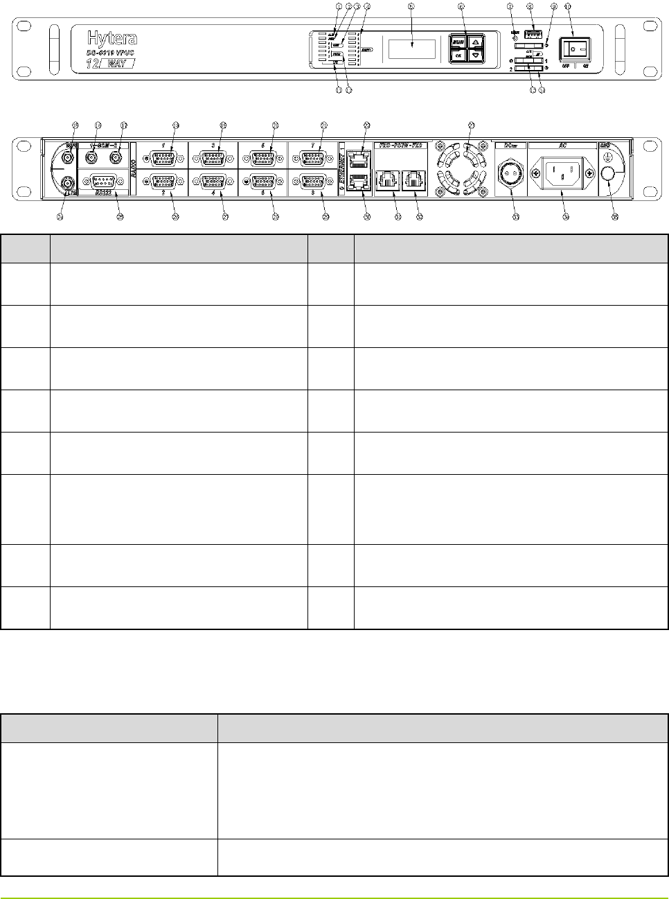
3.1 Product Controls
No. Part Name No. Part Name
1 Alarm Indicator 9 DC Power Inlet
2 Power Indicator 10 Radio 1 Connector (DB15)
3 Radio 1 Indicator 11 Radio 2 Connector (DB15)
4 Radio 2 Indicator 12 Serial Port (RS232)
5 LCD Display 13 Ethernet Port 0 (RJ45)
6 Function Keys (Menu/OK/Up/Down
Key)
14 Ethernet Port 1 (RJ45)
7 Reset Key 15 Ground Screw
8 Power Switch - -
3.2 LED Indicator
LED Indicator Gateway Status
Alarm Indicator (ALM)
z Glows red: the gateway is in the alarm state (this feature is not
available yet).
z Off: the gateway works properly.
Power Indicator (PWR) z Glows green: the gateway is on.
5
LED Indicator Gateway Status
z Off: the gateway is off.
Radio 1 Indicator (RADIO1)
z Off: the channel is idle.
z Glows orange: the gateway is transferring voice to Radio 1.
z Glows green: the gateway is receiving voice from Radio 1.
Radio 2 Indicator (RADIO2)
z Off: the channel is idle.
z Glows orange: the gateway is transferring voice to Radio 2.
z Glows green: the gateway is receiving voice from Radio 2.
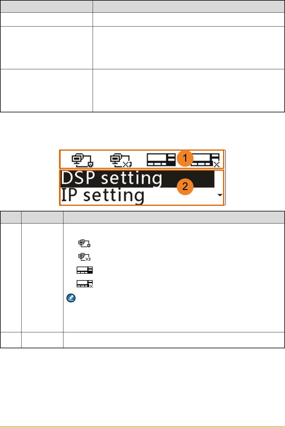
3.3 LCD Display
The display information on the LCD display is shown below:
No. Name Description
1 Status Bar
Displays the connection status of the Ethernet ports and the radios:
z : The Ethernet cable is connected successfully.
z : The Ethernet cable is not connected or connected improperly.
z : The connected radio is online.
z : The radio is not connected, or the connected radio is offline.
Note
The icons from left to right indicate the Ethernet port 0, Ethernet port 1, Radio 1
connector and Radio 2 connector respectively.
2 Menu Pane Displays the menus.

6
4. Basic Operations
4.1 Turning the Gateway On/Off
Caution
Turn off the connected radio(s) before turning off the gateway.
z To turn on the gateway, toggle the power switch to the “ON” position.
z To turn off the gateway, toggle the power switch to the “OFF” position.
4.2 Resetting the Gateway
To reset the gateway, long press the Reset key for five seconds. Then the gateway will restart and be
reset to factory default settings.
4.3 Making the Basic Settings
You can use the function keys beside the LCD display to make basic settings, including the digital signal
processing (DSP) settings, IP settings and language settings, and view information about the gateway.
Note
¾ To return to the previous menu from a submenu, press the Up/Down key to highlight “Back”, and
then press the OK key.
¾ To directly return to the main menu from a submenu, press the Menu key.
5.3.1 DSP Settings
You can set the DSP for voice calls. The DSP settings include the settings of voice activity detection
(VAD), sensitivity, call hang time and RX audio delay time. The VAD feature is used to detect if the radio
is transmitting, so as to request or release the talk right via the gateway software. Thus the feature can
avoid the failure of communications between the radios due to no talk right event (including talk right
request and release) or talk right event loss in the system.
After the VAD feature is enabled, the audio may be muted between syllables or during pauses in speech.
To avoid this problem, you can set the call hang time to keep the channel occupied within preset time.
The RX audio delay feature is used to buffer the voice packet for a period of time, so as to prevent the
received voice from being lost due to the situation that the server detects the voice event later than the
transfer of the voice packet.
Setting the VAD
Step 1 Press the Up key to highlight “DSP setting” in the main menu, as shown below.
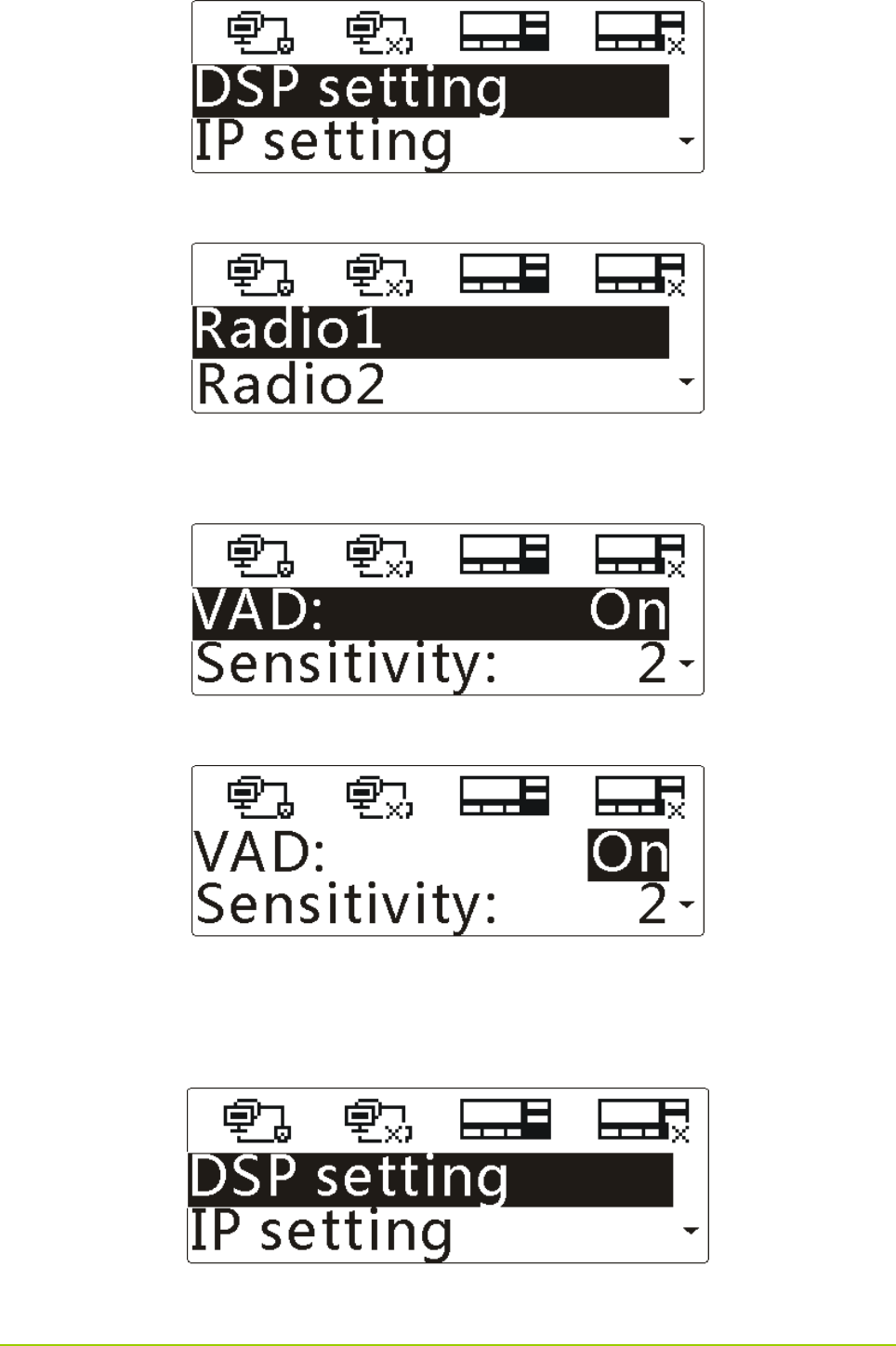
7
Step 2 Press the OK key to enter the menu, as shown below.
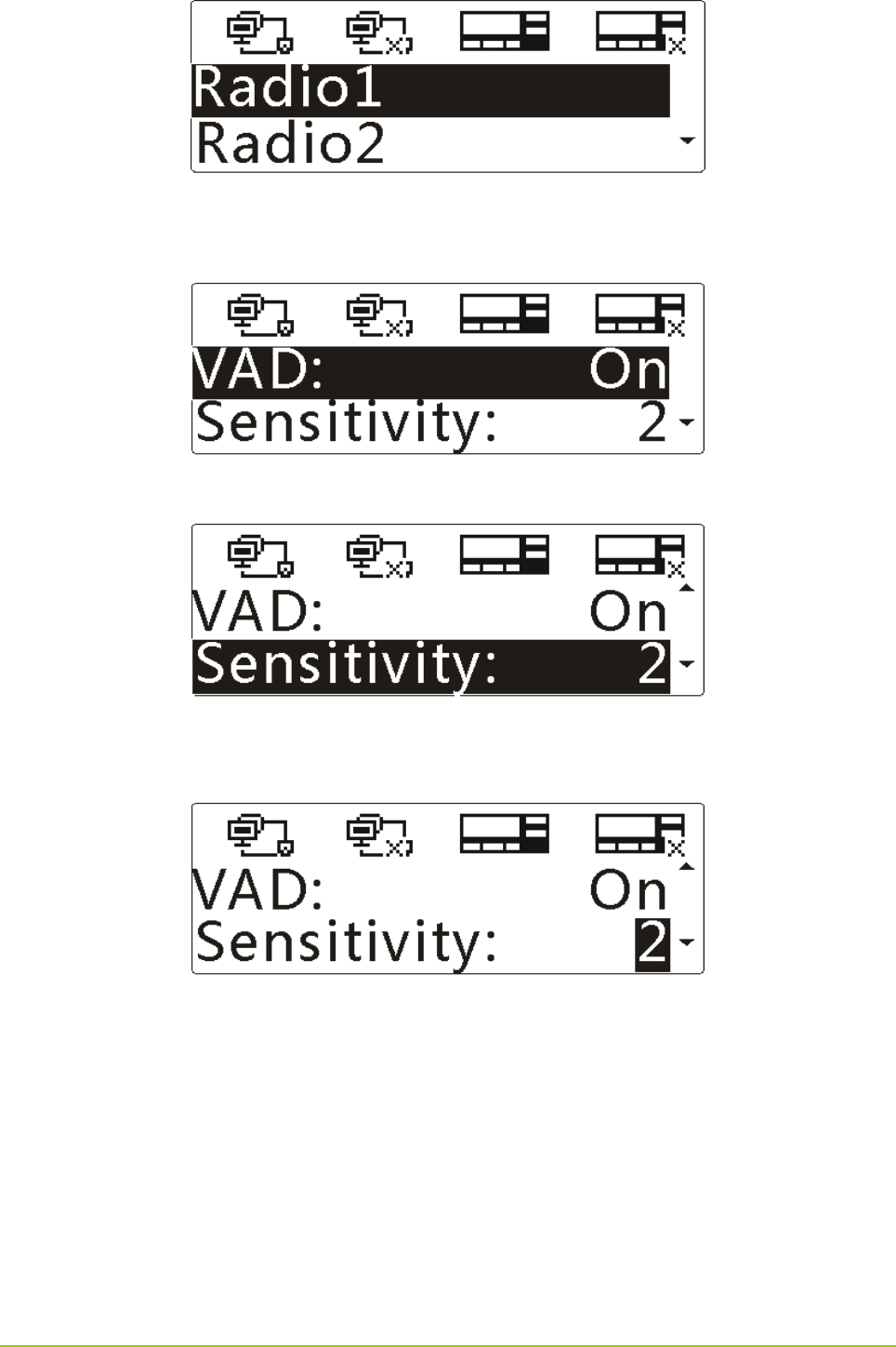
Step 3 Press the Up/Down key to highlight “Radio1” or “Radio2”, and then press the OK key to enter
the menu.
Step 4 Press the OK key to select “VAD”, and then press the Up/Down key to highlight “On” or “Off”.
Step 5 Press the OK key to finish.
Setting the Sensitivity
Step 1 Press the Up key to highlight “DSP setting” in the main menu, as shown below.
Step 2 Press the OK key to enter the menu, as shown below.
8
Step 3 Press the Up/Down key to highlight “Radio1” or “Radio2”, and then press the OK key to enter
the menu.
Step 4 Press the Down key to highlight “Sensitivity”, as shown below.
Step 5 Press the OK key, and then press the Up/Down key to set the sensitivity level, as shown below.
The smaller value indicates higher sensitivity.
Step 6 Press the OK key to finish.
Setting the Call Hang Time
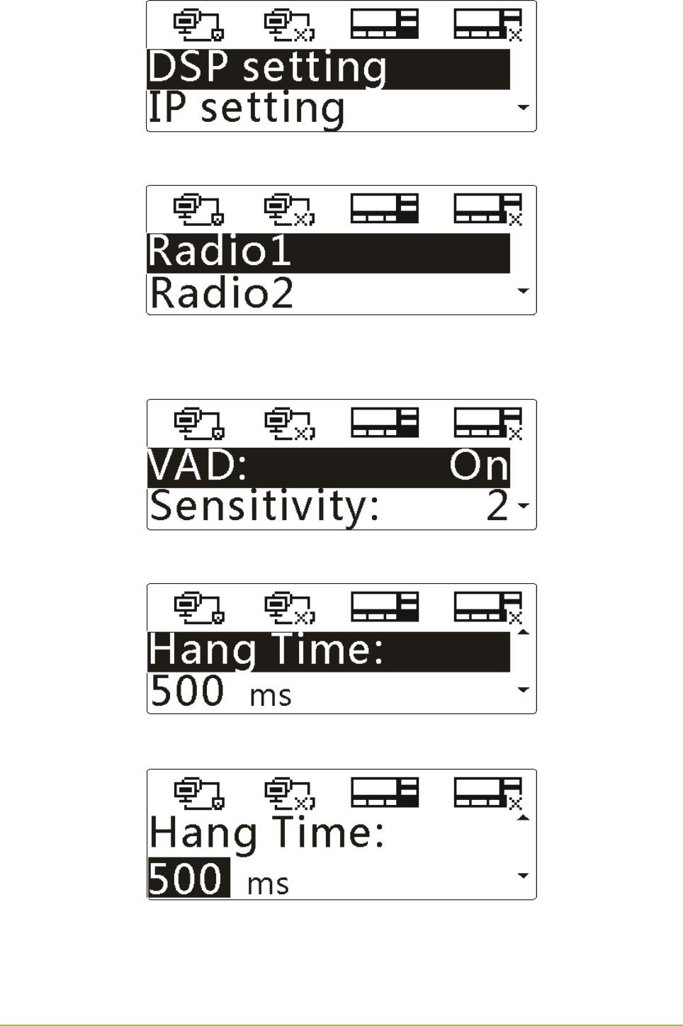
Step 1 Press the Up key to highlight “DSP setting” in the main menu, as shown below.
9
Step 2 Press the OK key to enter the menu, as shown below.
Step 3 Press the Up/Down key to highlight “Radio1” or “Radio2”, and then press the OK key to enter
the menu.
Step 4 Press the Down key to highlight “Hang Time”, as shown below.
Step 5 Press the OK key, and then press the Up/Down key to set the time, as shown below.
Step 6 Press the OK key to finish.
Setting the Rx Audio Delay Time
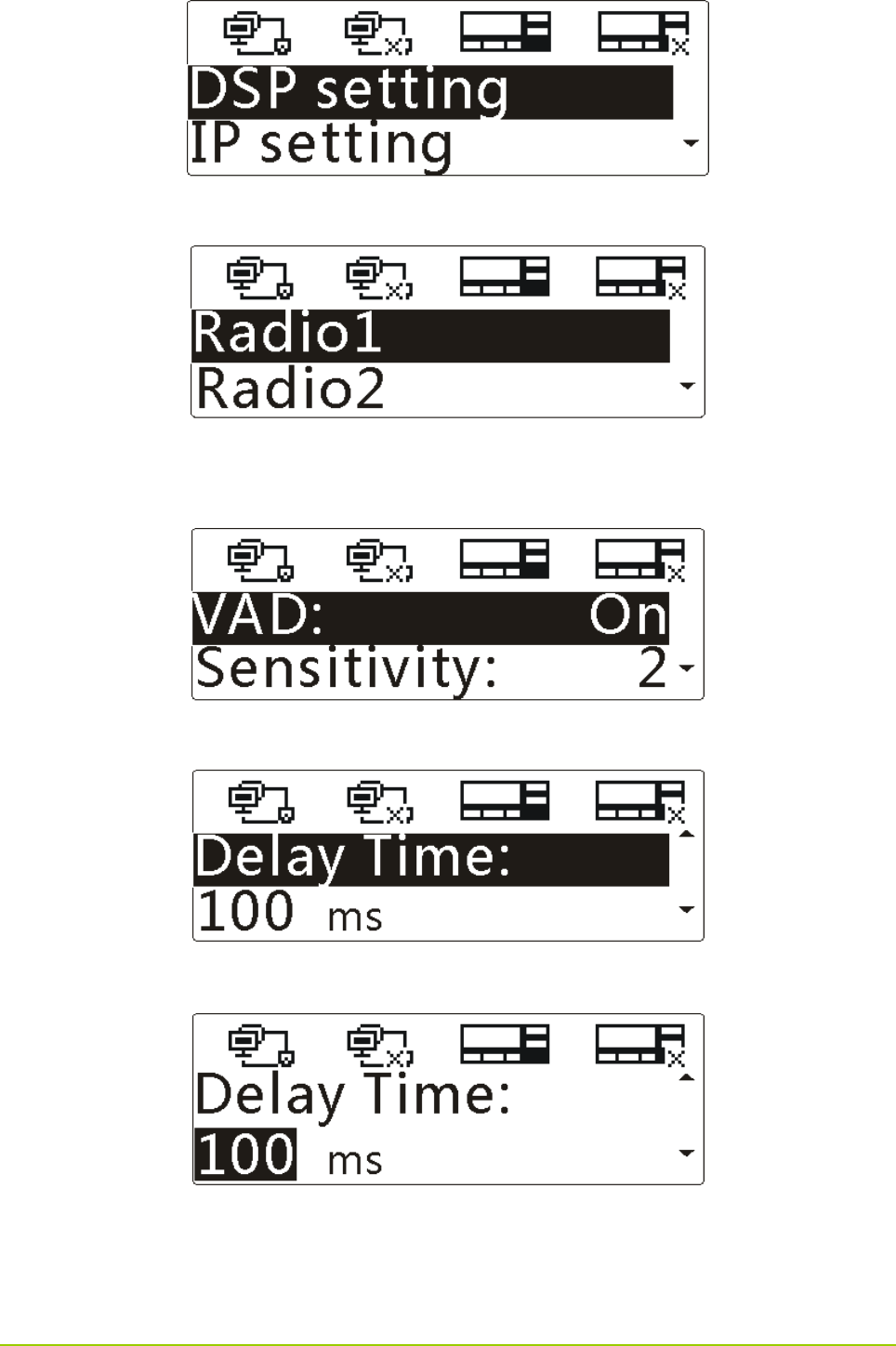
Step 1 Press the Up key to highlight “DSP setting” in the main menu, as shown below.
10
Step 2 Press the OK key to enter the menu, as shown below.
Step 3 Press the Up/Down key to highlight “Radio1” or “Radio2”, and then press the OK key to enter
the menu.
Step 4 Press the Down key to highlight “Delay Time”, as shown below.
Step 5 Press the OK key, and then press the Up/Down key to set the time, as shown below.
Step 6 Press the OK key to finish.
5.3.2 IP Settings
You can set the network card and the local IP address. The gateway has two Ethernet ports, each of
11
which is with a network card. The network cards can be enabled or disabled as per actual requirements.
To enable a network card, you need to set its IP address as the static IP address or a dynamic IP
address.
Setting the Network Card
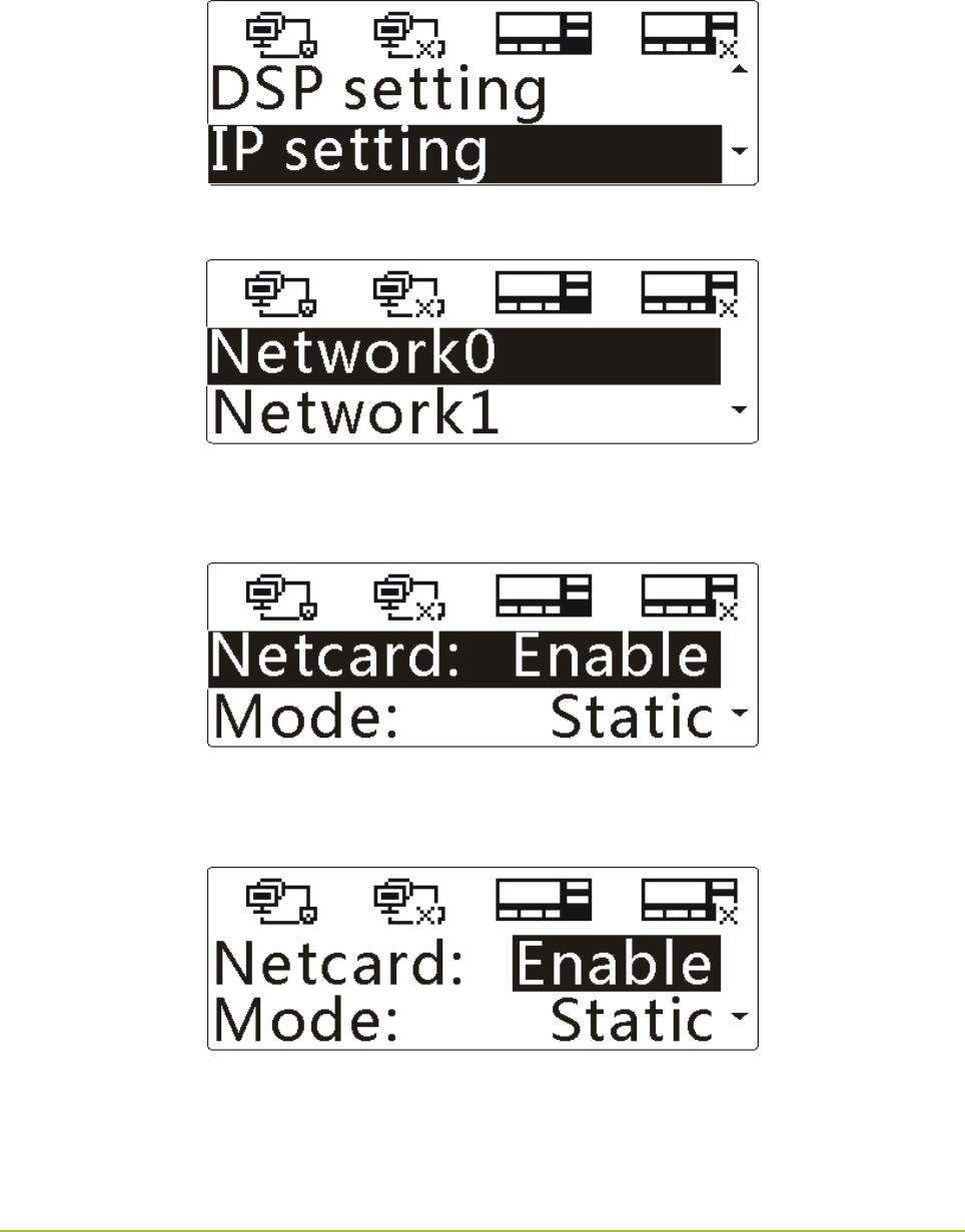
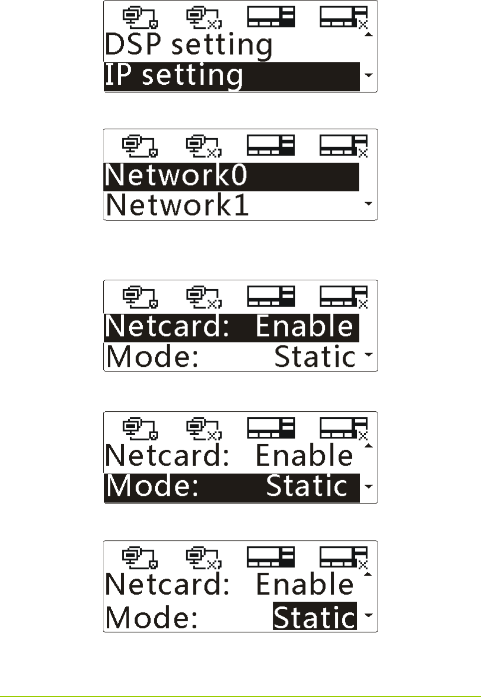
Step 1 Press the Up/Down key to highlight “IP settings” in the main menu, as shown below.
Step 2 Press the OK key to enter the menu, as shown below.
Step 3 Press the Up/Down key to highlight “Network0” or “Network1”, and then press the OK key to
enter the menu.
Step 4 Press the OK key to select “Netcard”, and then press the Up/Down key to highlight “Enable” or
“Disable”.
Step 5 Press the OK key to finish.
Setting the Local IP Address
z To set the static IP address
12
Step 1 Press the Up/Down key to highlight “IP setting” in the main menu, as shown below.
Step 2 Press the OK key to enter the menu, as shown below.
Step 3 Press the Up/Down key to highlight “Network0” or “Network1”, and then press the OK key to
enter the menu.
Step 4 Press the Down key to highlight “Mode”, as shown below.
Step 5 Press the OK key, and then press the Up/Down key to highlight “Static”, as shown below.
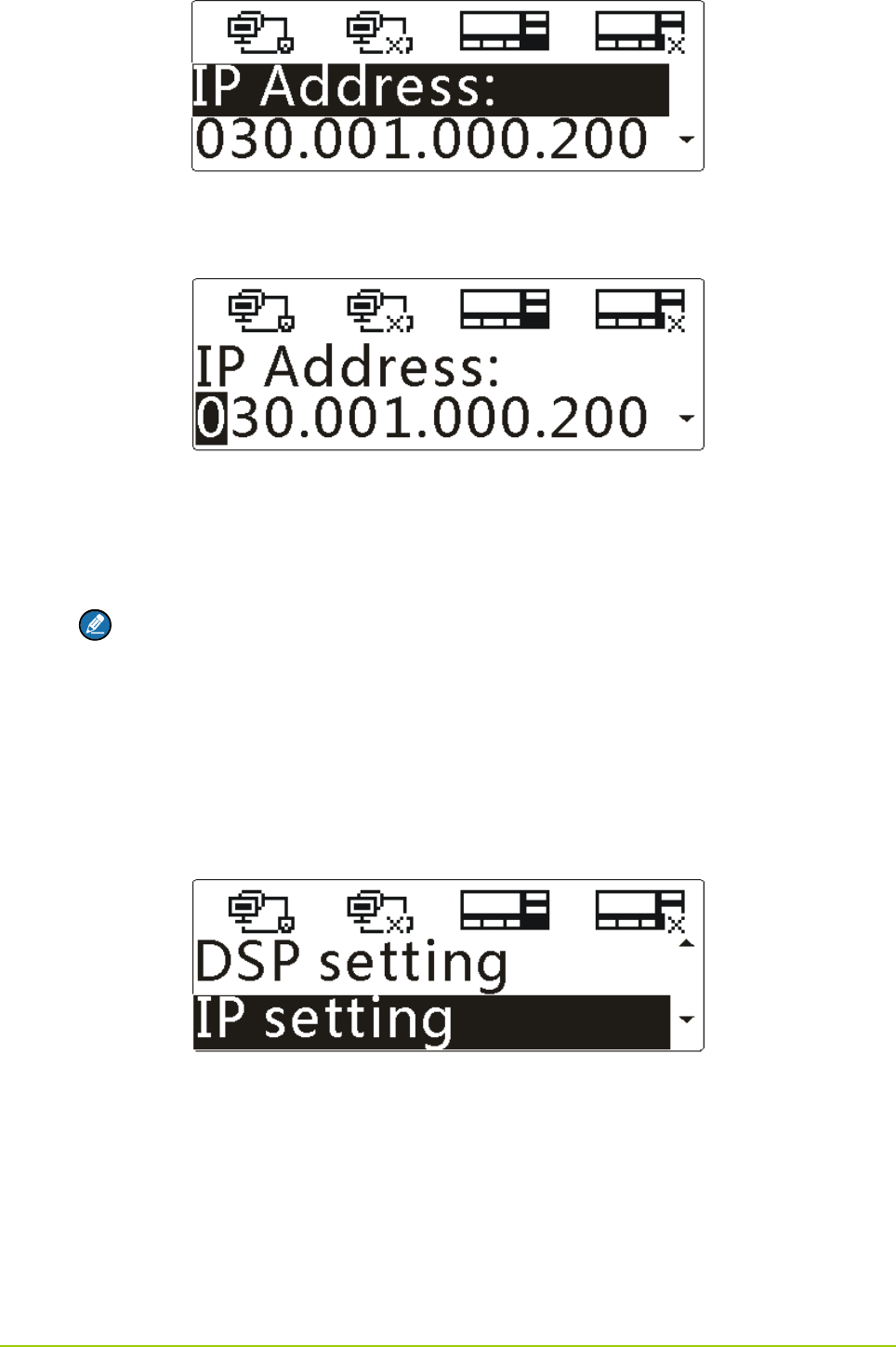
Step 6 Press the OK key to enter the menu, as shown below.
13
Step 7 Press the Up/Down key to highlight “IP Address”, and then press the OK key.
Then the first digit of the IP address is highlighted, as shown below.
Step 8 Press the Up/Down key to change the value, and then press the OK key to confirm the value.
Then the next digit will be highlighted. Repeat above-mentioned steps until you finish setting
the IP address.
Note
Upon wrong settings of the IP address, the corresponding prompt will appear, and then you
need to set it again.
Step 9 Follow the same operations in Step 7 and Step 8 to set the “Subnet Mask” and “Default GW”
respectively.
z To set the dynamic IP address
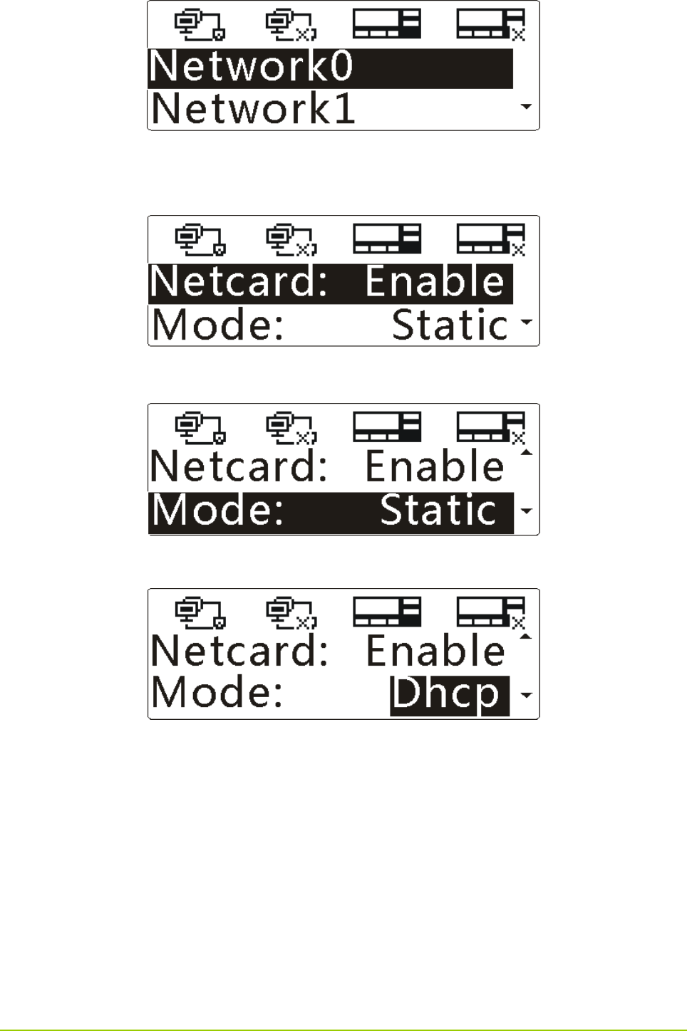
Step 1 Press the Up/Down key to highlight “IP setting” in the main menu, as shown below.
Step 2 Press the OK key to enter the menu, as shown below.
14
Step 3 Press the Up/Down key to highlight “Network0” or “Network1”, and then press the OK key to
enter the menu.
Step 4 Press the Down key to highlight “Mode”, as shown below.
Step 5 Press the OK key, and then press the Up/Down key to highlight “Dhcp”, as shown below.
Step 6 Press the OK key to finish.
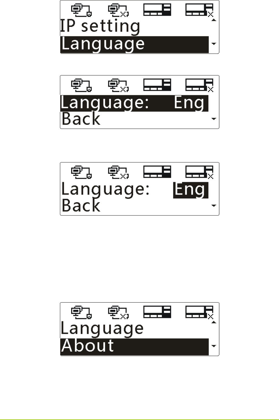
5.3.3 Language Settings
You can set Chinese or English as the display language.
Step 1 Press the Up/Down key to highlight “Language” in the main menu, as shown below.
15
Step 2 Press the OK key to enter the menu, as shown below.
Step 3 Press the OK key, and then press the Up/Down key to highlight “中文” or “Eng”, as shown
below.
Step 4 Press the OK key to finish.
5.3.4 Gateway Information Check
You can view the gateway information, such as the software and hardware versions, network and the
storage.
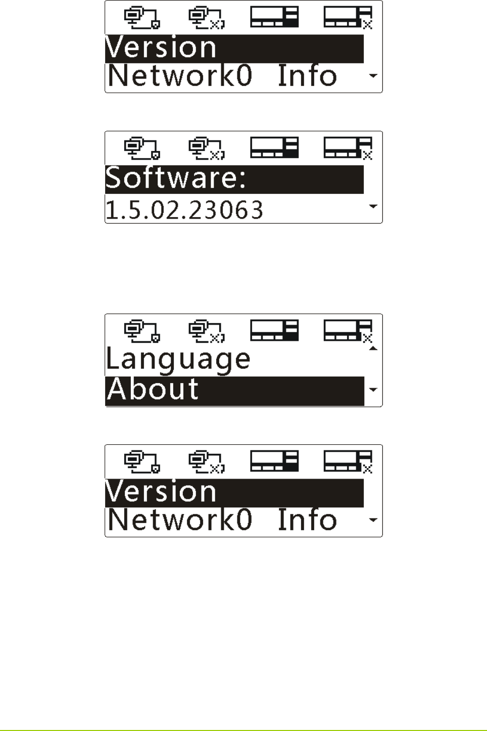
Viewing the Version
Step 1 Press the Down key to highlight “About” in the main menu, as shown below.
Step 2 Press the OK key to enter the menu, as shown below.
16
Step 3 Press the OK key to enter the menu, as shown below.
Step 4 Press the Up/Down key to view the version of software and hardware.
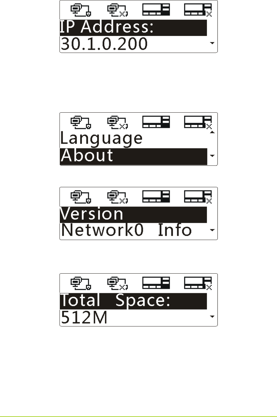
Viewing the Network Information
Step 1 Press the Down key to highlight “About” in the main menu, as shown below.
Step 2 Press the OK key to enter the menu, as shown below.
Step 3 Press the Up/Down key to highlight “Network0 Info” or “Network1 Info”, and then press the OK
key to enter the menu.
17
Step 4 Press the Up/Down key to view the local IP address, subnet mask, default gateway and MAC
address.
Viewing the Storage Information
Step 1 Press the Down key to highlight “About” in the main menu, as shown below.
Step 2 Press the OK key to enter the menu, as shown below.
Step 3 Press the Down key to highlight “Storage Info”, and then press the OK key to enter the menu,
as shown below.
Step 4 Press the Up/Down key to view the total space, available space and file system status.

18
5. Product Configuration
Before using the gateway, you need to configure it and the server. For detailed configuration, see the
DS-6610 VPUC Configuration Guide in the disc.

19
6. Care and Cleaning
To guarantee optimal performance as well as a long service life of the product, please follow the tips
below.
Product Care
z Do not pierce, hit, throw, forcibly shake or scrape the product.
z Keep the product far away from substances that can corrode the circuit.
z Keep the product dry.
z Keep the product away from overheating, which may shorten lifespan of the electronic parts, or even
distort or melt the plastic parts.
z Keep the product away from extreme cold; otherwise, the circuit board may be damaged by vapor
generated when the product is used at normal temperature.
Product Cleaning
Caution
Turn off the product and remove the power cord before cleaning.
z Clean up the dust and fine particles on the product surface regularly with a clean and dry lint-free
cloth or a brush.
z Use neutral cleanser and a non-woven fabric to clean the keys and case after long-time use. Do not
use chemical preparations such as stain removers, alcohol, sprays or oil preparations, so as to avoid
surface and case damage.
z Make sure the product is completely dry before use.