Hytera Communications DTM6000U1 DMR Data Modem User Manual
Hytera Communications Corporation Limited DMR Data Modem
User Manual

DTM-6000 Data Transmission Modem
User Manual

Copyright Information
Hytera is the trademark or registered trademark of Hytera Communications Corporation Limited (the Com-
pany)in People's Republic of China (PRC) and/or other countries or areas. The Company retains the own-
ership of its trademarks and product names. All other trademarks and/or product names that may be used
in this manual are properties of their respective owners.
The product described in this manual may include the Company's computer programs stored in memory
or other media.Laws in PRC and/or other countries or areas protect the exclusive rights of the Company
with respect to its computer programs.The purchase of this product shall not be deemed to grant, either
directly or by implication, any rights to the purchaser regarding the Company's computer programs.The
Company's computer programs may not be copied, modified, distributed, decompiled, or reverse-engin-
eered in any manner without the prior written consent of the Company.
Disclaimer
The Company endeavors to achieve the accuracy and completeness of this manual, but no warranty of
accuracy or reliability is given.All the specifications and designs are subject to change without notice due
to continuous technological development.No part of this manual may be copied, modified, translated, or
distributed in any manner without the prior written consent of the Company.
We do not guarantee, for any particular purpose, the accuracy, validity, timeliness, legitimacy or com-
pleteness of the third-party products and contents involved in this manual.
If you have any suggestions or would like to learn more details, please visit our website at:
http://www.hytera.com.
FCC Regulations
Federal Communication Commission (FCC) requires that all radio communication products should meet the requirements set
forth in the above standards before they can be marketed in the U.S, and the manufacturer shall post a RF label on the product
to inform users of operational instructions, so as to enhance their occupational health against exposure to RF energy.
FCC Statement
This equipment has been tested and found to comply with the limits for a Class B digital device, pursuant to part 15 of
FCC Rules. These limits are designed to provide reasonable protection against harmful interference in a residential
installation. This equipment generates and can radiate radio frequency energy. If not installed and used in accordance
with the instructions, it may cause harmful interference to radio communications. However, there is no guarantee that
interference will not occur in a particular installation. Verification of harmful interference by this equipment to radio or
television reception can be determined by turning it off and then on. The user is encouraged to try to correct the
interference by one or more of the following measures:
Reorient or relocate the receiving antenna. Increase the separation between the equipment and receiver.
Connect the equipment into an outlet on a different circuit to that of the receiver's outlet.
Consult the dealer or an experienced radio/TV technician for help.
Operation is subject to the following two conditions:
This device may not cause harmful interference.
This device must accept any interference received, including interference that may cause undesired operation.
Note: Any changes or modifications to this unit not expressly approved by the party responsible for compliance could
void the user's authority to operate the equipment.
Antenna gain must not exceed 3.5dBi(DMR) and 2.5dBi(Wifi).
The antenna must be installed complying with the requirements of manufacturer or supplier, and it must be at least
6 0cm away from human body.
2.1091
Compliance with RF Exposure Standards
Hytera's radio complies with the following RF energy exposure standards and guidelines:
United States Federal Communications Commission, Code of Federal Regulations; 47 CFR § 1.1307, 1.1310 and
Institute of Electrical and Electronic
Engineers (IEEE) C95.1:2005 Edition
titute of Electrical and E lectronic Engineers (IEEE)
American National Standa rds Institute (ANSI) / Ins
C95. 1:2005; Canada RSS102 Issue 5 March 2015
Documentation Information
Intended Audience
This document is intended to be read by:
lSales engineers
lInstallation engineers
lTechnical support engineers
lCommon users
Documentation Conventions
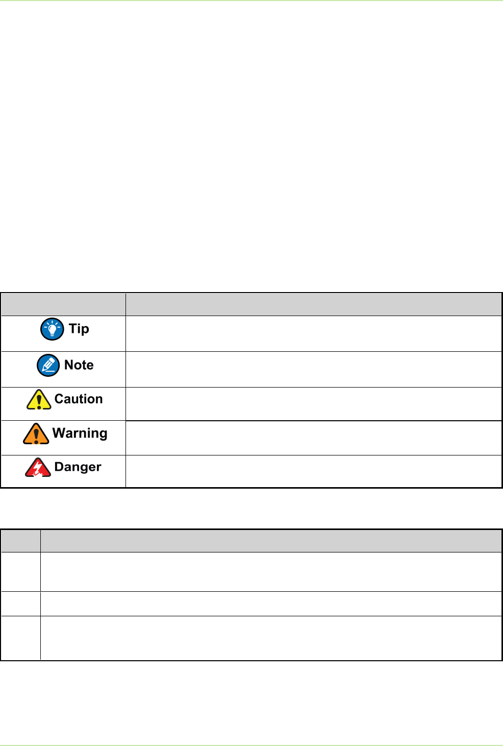
Icon Conventions
Icon Meaning
Indicates information that can help you make better use of your product.
Indicates references that can further describe the related topics.
Indicates situations that could cause data loss or equipment damage.
Indicates situations that could cause minor personal injury.
Indicates situations that could cause major personal injury or even death.
Notational Conventions
Item Meaning
" " The quotation marks enclose the name of a software interface element. For example, click
"OK".
Bold The text in boldface denotes the name of a hardware button. For example, press the PTT key.
>The symbol directs you to access a multi-level menu. For example, to select "New"from the
"File"menu, we will described it as follows: "File > New".
Revision History
1
Documentation Information User Manual

User Manual Documentation Information
Document
Version
Product
Version
Release
Date Description
00 V1.0 September
2018 Initial release.
2

1. Packing List
Item Quantity Item Quantity
DTM-6000 Main Unit 1 Wi-Fi Antenna 1
DC Power Cord 1 GPS Antenna 1
RF Antenna Base 1 RF Antenna 1
lItems in the packing list are standard equipment. Optional accessories such as the M3
and M4 screws, latch and bracket for the DIN rail installation need to be purchased
separately.
lPictures listed in this document are for reference only.
3
User Manual 1. Packing List

2. Product Overview
2.1 Introduction
The Supervisory Control and Data Acquisition (SCADA)system, a distributed control system (DCS)and
power automation monitoring system on the basis of computers, provides services such as data
collecting, data monitoring and process control, and is also widely used in industries including:
lElectricity
lMetallurgy
lPetroleum
lChemical industry
lGas
lRailway
The SCADA data transmission scheme is tailored to transmit data between the third party control center
and the remote terminal unit (RTU)by the SCADA gateway and the data transmission modem, which
adopts DTM-6000.
4
User Manual 2. Product Overview
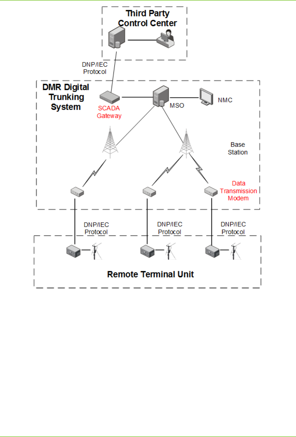
DTM-6000 is designed to obtain the original data after parsing the DNP/IEC protocol, then encapsulate
the data on the basis of the DMR protocol, and finally deliver the data to the third party control center
through the PDT/DMR digital trunking network for the administrators to browse.
DTM-6000 has the following advantages:
lSupports end-to-end encryption (E2EE), assuring safety and reliability.
lSupports data transmission in the private mobile radio (PMR) networks.
lIt can be deployed in remote and unfrequented areas or in areas with harsh conditions for automatic
data transmission, lowing the labor cost.
lSupports multiple frequencies including UHF1, UHF2 and VHF.
5
2. Product Overview User Manual
lProvides data transmission services for networks with different coverage scales (including small,
medium and large) on the basis of DMR digital trunking network.
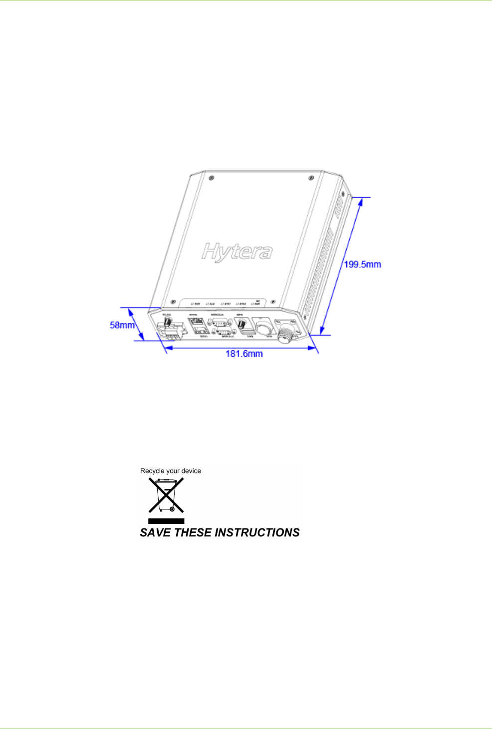
2.2 Appearance
DTM-6000 needs to be placed on the cabinet horizontally, or hung on the cabinet through ears; it cannot
be wall-mounted.
Its appearance and dimensions are shown in the figure below.
It is recommended to install DTM-6000 at places where children cannot reach.
The Waste Electrical and Electronic Equipment (WEEE) logo shown below appears on the product to
indicate that this product must not be disposed off or dumped with your other household wastes. You are
liable to dispose of all your electronic or electrical waste equipment by relocating over to the specified
collection point for recycling. of such hazardous waste.
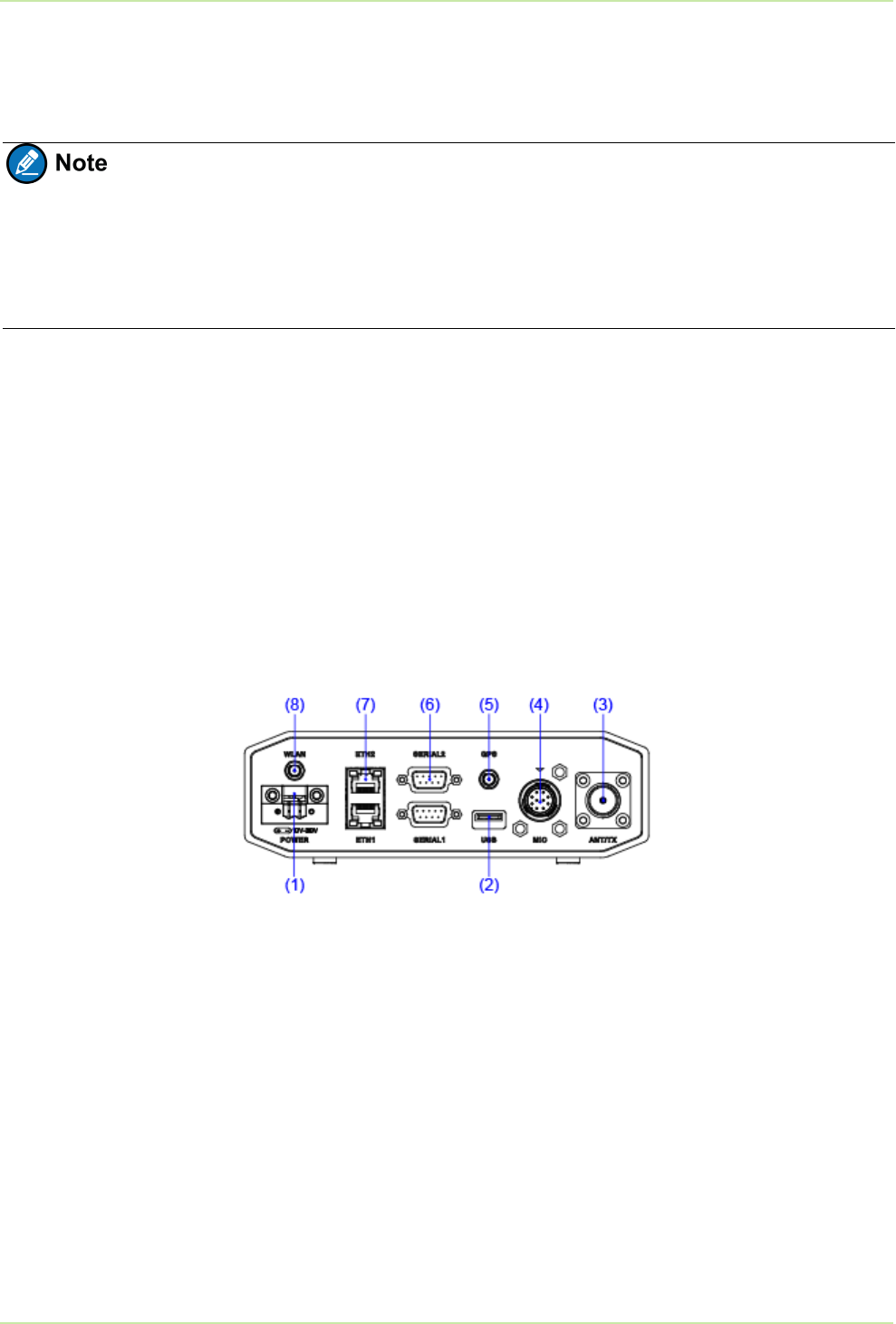
2.3 Interfaces
The interfaces of DTM-6000 locate on the top panel.
6
User Manual 2. Product Overview
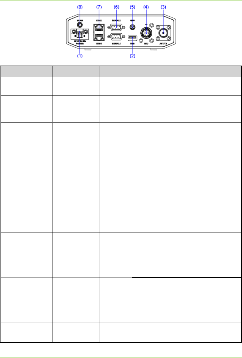
No. Identifier Name Connector Description
1 POWER Power inlet / Connects to the DC power supply, with DC
voltage range of 12 V to 30 V.
2 USBUSB interface USB-Type A
Connects to USB memory. The upgrade
program of DTM-6000 is stored in a USB
memory.
3 ANT/TX Antenna feeder
interface BNC
Connects to the antenna feed system.
lReceiving and transmitting wireless signal
from the base stations of DMR Trunking
System in trunking mode.
lReceiving and transmitting wireless signal
from other DTM-6000 in standard mode.
4 MIC Aviation
connector DB26
Connects to the PC through a programming
cable, allowing parameter configuration of
DTM-6000.
5 GPS GPS antenna
feeder interface SMA-F Connects to the GPS antenna feeder,
allowing GPS positioning of DTM-6000.
6 SERIAL Serial port DB9
DTM-6000 has two serial ports, enabling
connection of two RTUs with serial ports at the
same time. DTM-6000 receives data from
RTU through the serial port, and transmits
data to the third party control center.
7 ETHEthernet port RJ-45
DTM-6000 has two Ethernet ports, enabling
connection of two RTUs with Ethernet ports at
the same time. DTM-6000 receives data from
RTU through the Ethernet port, and transmits
data to the third party control center.
8 WLAN Wi-Fi antenna
interface SMA-F Connects to the Wi- Fi antenna, providing
access point for interconnection of Wi- Fi
7
2. Product Overview User Manual
No. Identifier Name Connector Description
devices.
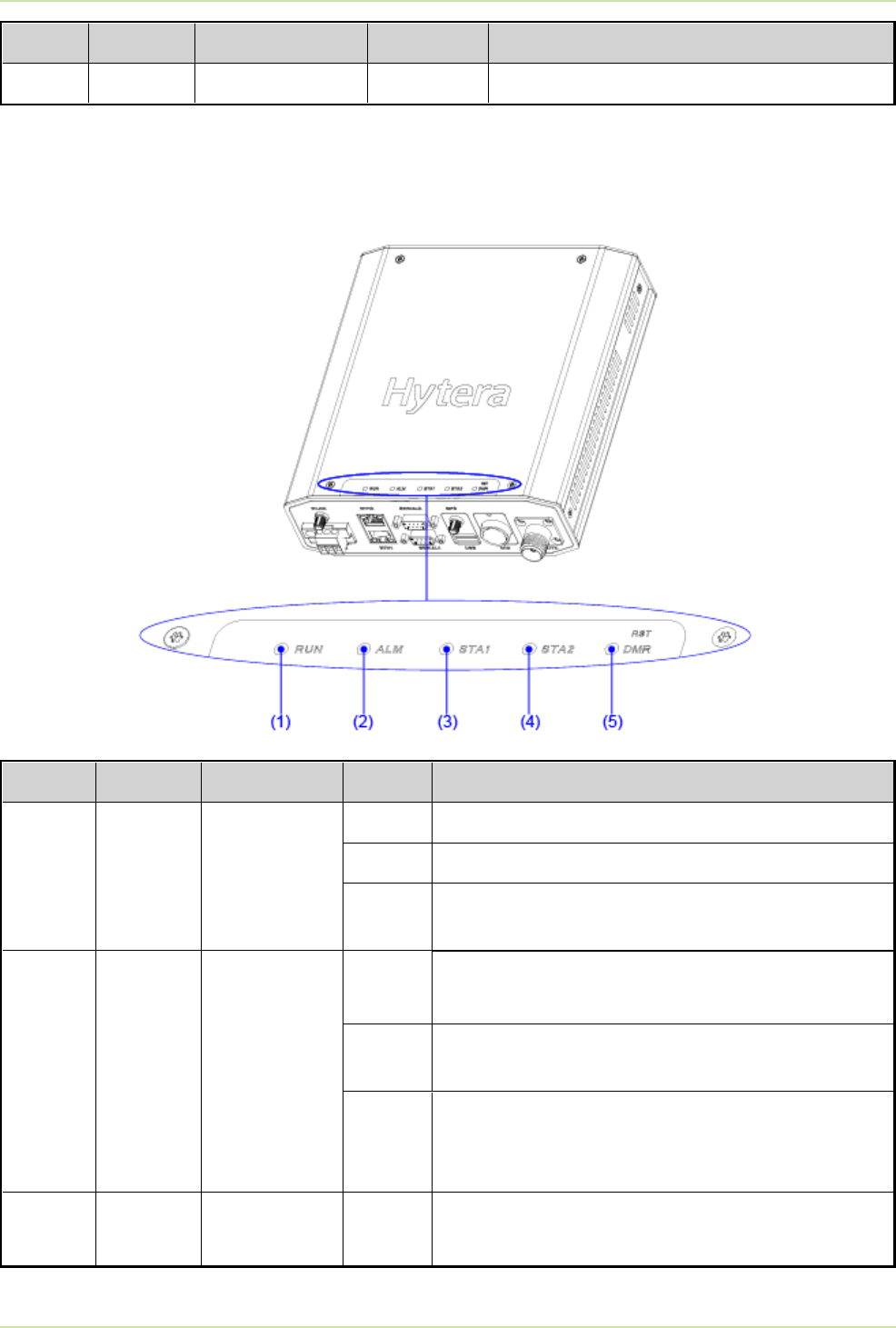
2.4 LED Indicators
The five indicators of DTM-6000 are described in the table below.
No. Identifier Color Status Description
1 RUN Green
Glowing DTM-6000 is loading the kernel through uboot.
Off DTM-6000iis booting.
Flashing DTM-6000 completes booting, and is running
normally.
2 ALMGreen/Red
Glowing
green DTM-6000 is being upgraded through USB memory.
OffDTM-6000 is communicating with the DMR Trunking
System normally.
Glowing
red
DTM-6000 fails to register to the DMR Trunking
System, or the DTM-6000 fails to communicate with
the DMR Trunking System.
3 STA1 Green/Orange Flashing
green Serial port 1 is transferring data through RS-232.
8
User Manual 2. Product Overview

No. Identifier Color Status Description
Flashing
orange Serial port 1 is transferring data through RS-485.
Glowing
green
Serial port 1 is working at RS-232 data transmitting
mode.
Glowing
orange
Serial port 2 is working at RS-485 data transmitting
mode.
4 STA2 Status indicator for serial port 2. Its Color, Status and Description are the same
as the STA1 indicator.
5 DMR Green/Red
Flashing
green
DTM-6000 is transmitting data to the DMR Trunking
System.
Flashing
red
DTM-6000 is receiving data from the DMR Trunking
System.
Off The link between DTM-6000 and the DMR Trunking
System is idle.
9
2. Product Overview User Manual
3. Installing DTM-6000
3.1 Procedures
Install DTM-6000 to the cabinet, with a bracket to fix it during installation. For the installation of the bracket
and DTM-6000, contact a technical support engineer.
3.2 Connecting the Cables
As the downlink device of DTM-6000, RTU can be connected to DTM-6000 in two ways:
lIf serial port is supported, the RTU can be connected to DTM-6000 through RS-232 or RS-485 by a
serial cable.
lIf Ethernet port is supported, the RTU can be connected to DTM-6000 through RJ-45 by a net cable.
1. Connect Wi-Fi antenna to the Wi-Fi antenna interface (Interface 8) and tighten the joint.
2. Connect the GPS antenna feeder to the GPS antenna feeder interface (Interface 8) and tighten the
joint.
3. Connect the antenna feeder to the antenna feeder interface (Interface 3), and tighten the joint.
4. (Optional) Connect the RTU with data cable type of RJ-45 to the Ethernet port (Interface 7) of DTM-
6000 through a net cable.
5. (Optional) Connect the RTU with data cable type of RS-232 or RS-485 to the serial port (Interface 6) of
DTM-6000 through a serial cable, and fasten the screws on both sides of the joint.
6. Connect the power cord to the power inlet (Interface 1), and fasten the screws on the joint.
10
User Manual 3. Installing DTM-6000
This device requires controlled installation location by professional installers.
The installer shall install the authorized antenna, and unauthorized antenna shall not
be installed on this product.

4. Troubleshooting
Phenomena Analysis Solution
DTM-6000 fails to power on.
lThe power cord is not
connected.
lThe power cord is in poor
contact.
lConnect the power cord.
lReconnect the power
cord.
The ALM indicator glows red.
lDTM-6000 fails to register to
the DMR Trunking System.
lDTM-6000 fails to
communicate with the DMR
Trunking System.
lConfirm whether DTM-
6000 is added, and is
distributed with data
transmission permission
on the DMR Trunking
System.
lConfirm whether the
antenna feeder is
connected to the antenna
feeder interface, and
DTM-6000 is in the signal
coverage of the DMR
Trunking System.
DTM-6000 fails to receive data
from RTU.
lDTM-6000 is not connected to
the RTU properly.
lThe data cable is damaged.
lReconnect DTM- 6000
with RTU through the
data cable.
lReplace the data cable.
If the above solutions cannot solve your problems, or you may have some other queries, please contact us
or your local dealer for more technical support.
11
User Manual 4. Troubleshooting
5. Care and Cleaning
To guarantee optimal performance as well as a long service life of the product, please follow the tips
below.
5.1 Product Care
lDo not pierce, strike, throw or scrape the product.
lKeep the product away from substances that can corrode the circuitry.
lKeep the product dry.
lKeep this product far away from overheating, which may shorten lifespan of the electronic parts, or
even distort or melt the plastic parts.
lKeep this product far away from extreme cold. Otherwise, the circuit board may be damaged by vapor
generated when the product temperature rises to normal degrees.
5.2 Product Cleaning
Before cleaning, disconnect the DTM-6000 from power supply.
lClean up the dust and fine particles on the product surface and charging piece with a clean and dry lint-
free cloth or a brush regularly.
lUse a non-woven cloth with neutral cleanser to clean the device after long-time use. Do not use
chemical preparations such as stain removers, alcohol, sprays or oil preparations, so as to avoid
potential damage on the surface. Make sure the product is completely dry before use.
12
User Manual 5. Care and Cleaning

6. Specifications
Item Value
Operating Frequency l
Operating Bandwidth 12.5 KHz
Channel Spacing
Adjustable in the following three channel spacings.
l12.5 kHz
TX Power Adjustable between 1–25 W.
Power Input DC 12–30 V
Maximum Power ≤ 95 W
Sensitivity 0.3 μV/BER5%
Conducted/Radiated Emission
l–36 dBm < 1 GHz
l–30 dBm > 1 GHz
Adjacent Channel Power
l60 dB@12.5 KHz
Modulation Limiting
l±2.5 KHz@12.5 KHz
Ingress Protection Rating IP20
Dimensions (H×W×D) 58 mm×186 mm×199.5 mm (excluding the foot
pad)
Weight ≤ 2.5 kg
Operating Temperature –30°C to +60°C
13
User Manual 6. Specifications
UHF: 400–470 MHz

Item Value
Storage Temperature –40°C to +70°C
Operating Humidity <95% (non-condensing)
MTBF ≥30,000 h
ESD
IEC 61000-4-2 (level 4)
lContact discharge: ±8 kV
lAir discharge: ±15 kV
14
6. Specifications User Manual

7. Abbreviations
Abbreviation Full Name
ALM Alarm
ANT Antenna
BER Bit Error Rate
BNC Bayonet Nut Connector
DB Data Bus
DC Direct Current
DMR Digital Mobile Radio
DNP Distributed Network Protocol
DTM Data Transmission Modem
ETH Ethernet
GPS Global Positioning System
IEC International Electrotechnical Commission
IP Ingress Protection
MIC Microphone
MTBF Mean Time Between Failures
PC Personal Computer
PDT Professional Digital Trunking
PTT Push-to-Talk
RS Recommended Standard
RTU Remote Terminal Unit
SCADA Supervisory Control And Data Acquisition
SMA Sub Miniature A
STA Status
TX Transit
UHF Ultra High Frequency
USB Universal Serial Bus
VHF Very High Frequency
WLAN Wireless Local Area Network
15
User Manual 7. Abbreviations

is the trademark or registered trademark of Hytera Communications Corporation Limited.
2018 Hytera Communications Corporation Limited. All Rights Reserved.