Hytera Communications EPACK100F4 Digital WANET Repeater User Manual
Hytera Communications Corporation Limited Digital WANET Repeater Users Manual
Contents
- 1. Users Manual
- 2. User Manual
Users Manual
To Costumers
Thank you very much for your favor of our products! This manual aims to enable you
quickly grasp the use of the product.
This manual applies to the following model:
E-pack100 Digital WANET Repeater
i
Icon Conventions
The following icons are used in this manual. The explanation of icons are
as follows:
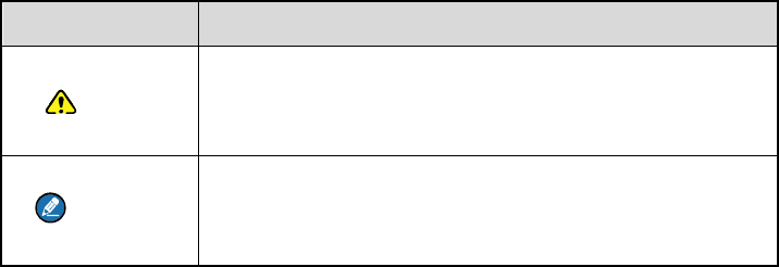
Icon Description
Caution Indicates situations that could cause data loss or
equipment damage.
Comment Indicates notes that serves as supplement, illustration
or emphasis to the main content.
Copyright Information
Hytera is the trademark or registered trademark of Hytera Communications
Corporation Limited (the Company) in People's Republic of C hina (PRC)
and/or other countries or areas. The Company retains the ownership of its
trademarks and pro duct names. All other trade marks and/or prod uct
names that may be used in this manual are properties of th eir respective
owners.
The prod uct described in this man ual may in clude the Compan y's
computer programs stored in memory or other media. Laws in PRC and/or
other countries or areas protect the exclusive righ ts of the Co mpany with
respect to its computer programs. The purchase of this product shall not be
deemed to grant, either directly or by implication, any rights to the
purchaser regarding the Compan y's computer programs. The Compan y's
ii
computer programs may not be copied, modified, distributed, decompiled,
or reverse-engineered in any mann er without the prior w ritten consent of
the Company.
Disclaimer
The Compa ny ende avors to achieve the accuracy and completeness of
this manual, but no warranty of accuracy or reliability is given. All the
specifications and desig ns are subje ct to change without notice due to
continuous technological development. No part of this man ual may be
copied, modified, translated, or distributed in any manner without the prior
written consent of the Company.
We do not guar antee, for any pa rticular pur pose, the accuracy, validity,
timeliness, legitimacy or complet eness of the th ird-party pr oducts and
contents involved in this manual.
If you ha ve any sug gestions or w ould like to receive mor e in formation,
please v isit our website at: http ://www.hytera.com, or call our serv ice
hotline 400-830-7020.
Federal Communications Commission (FCC) Regulatory
Requirements
According to the Fed eral C ommunications Commission regulato ry
requirements, the terminals must comply with the FCC's rules on
radiofrequency radiation, otherwise t he prod ucts shall not be sold in the
iii
U.S market. Besides, the manufacture shall be a sked to post a label o n
products informing costumers of considerations and improving th e
costumers’ awareness of radiation protection.
Radiofrequency Radiation Control and Operation Instructions
In order to e nsure the best perform ance of products and ensure that the
radiation restrictions related to o ccupations or environme nts are met, the
delivery time shall not exceed 50% of the rated factor.
FCC Regulations
Federal Communication Commission (FCC) requires that all radio
communication products should meet the requirements set forth in the
above standards before they can be marketed in the U.S, and the
manufacturer shall post a RF label on the product to inform users of
operational instructions, so as to enhance their occupational health against
exposure to RF energy.
FCC Statement
This equipment has been tested and found to comply with the limits for a
Class B digital device, pursuant to part 15 of FCC Rules. These limits are
designed to provide reasonable protection against harmful interference in a
residential installation. This equipment generates and can radiate radio
frequency energy. If not installed and used in accordance with the
instructions, it may cause harmful interference to radio communications.
However, there is no guarantee that interference will not occur in a
iv
particular installation. Verification of harmful interference by this equipment
to radio or television reception can be determined by turning it off and then
on. The user is encouraged to try to correct the interference by one or
more of the following measures:
Reorient or relocate the receiving antenna. Increase the separation
between the equipment and receiver.
Connect the equipment into an outlet on a different circuit to that of the
receiver's outlet.
Consult the dealer or an experienced radio/TV technician for help.
Operation is subject to the following two conditions:
This device may not cause harmful interference.
This device must accept any interference received, including
interference that may cause undesired operation.
Note: Changes or modifications to this unit not expressly approved by the
party responsible for compliance could void the user's authority to operate
the equipment.
Operational Instructions and Training Guidelines
To ensure optimal performance and compliance with the
occupational/controlled environment RF energy exposure limits in the
above standards and guidelines, users should transmit not more than 50%
of the time and always adhere to the following procedures:
DMR Antenna gain must not exceed 3.5dBi.
v
The antenna must be installed complying with the requirements of
manufacturer or supplier, and it must be at least 42 cm away from
human body.
Compliance with RF Exposure Standards
Hytera's radio complies with the following RF energy exposure standards
and guidelines:
United States Federal Communications Commission, Code of Federal
Regulations; 47 CFR § 1.1307, 1.1310 and 2.1091
American National Standards Institute (ANSI) / Institute of Electrical
and Electronic Engineers (IEEE) C95. 1:2005; Canada RSS102 Issue 5
March 2015
Institute of Electrical and Electronic Engineers (IEEE) C95.1:2005 Edition
ISEDC Statement
This device complies with Innovation, Science and Economic Development
Canada Compliance license-exempt RSS standard(s). Operation is subject
to the following two conditions:
This device may not cause harmful interference.
vi
This device must accept any interference received, including
interference that may cause undesired operation.
Le présent appareil est conforme aux CNR d'Industrie Canada applicables
aux appareils radio exempts de licence. L'exploitation est autorisée aux
deux conditions suivantes: (1) l'appareil ne doit pas produire de brouillage,
et (2) l'utilisateur de l'appareil doit accepter tout brouillage radioélectrique
subi, même si le brouillage est susceptible d'en compromettre le
fonctionnement
ISEDC Radiation Exposure Statement:
This device must be restricted to work related operations in an
Occupational/Controlled RF exposure Environment.
This equipment should be installed and operated with minimum distance
42cm between the radiator & your body.
ISEDC exposition aux radiations:
Ce dispositif doit être limité aux opérations liées au travail dans un
environnement d'exposition RF professionnel/contrôlé.
Cet équipement doit être installé et utilisé avec un minimum de 42cm de
distance entre le radiateur et votre corps.
vii
EU Regulatory Conformance
As certified by the qualified laboratory, the product is in compliance with
the essential requirements and other relevant provisions of the Directive:
2014/53/EU
2006/66/EC
2011/65/EU
2012/19/EU
Please note that the above information is applicable to EU countries only.
The maximum antenna gain is 3.5dBi, which is calculated in the EIRP. The
distance from observation point to the antenna is 120cm.
viii
Content
1. Packing List .......................................................................................... 1
2. Product Component ............................................................................. 2
2.1 Host .................................................................................................. 2
2.2 Palm Microphone .............................................................................. 4
3. Installation ............................................................................................ 6
3.1 Installation Requirements ................................................................. 6
3.2 Host Installation ................................................................................ 6
3.3 Check after Installation ..................................................................... 8
4. Basic Operation .................................................................................... 9
4.1 Power on .......................................................................................... 9
4.2 Power off .......................................................................................... 9
4.3 GSM Link Building ............................................................................ 9
4.4 Switch Channel ................................................................................. 9
4.5 Host Information Query ..................................................................... 9
5. Fault Handling .................................................................................... 11
6. Maintenance and Cleaning ................................................................ 14
7. Accessories Purchase ....................................................................... 15
8. Scope and Duration of Warranty ...................................................... 16
1
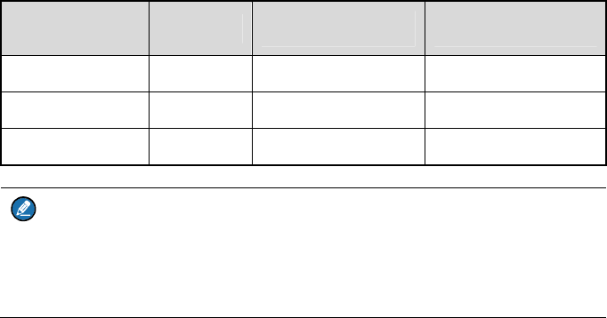
1. Packing List
The packing case conta ins the follo wing items. If there is any loss or da mage, please
contact the dealer or our company.
Items Number Items Number
Host 1 Palm Mircophone 1
Antenna 1 Mannual 1
Battery 1
Comment
The pictures in this manu al are for re ference on ly. Ple ase refer to the actual
products.
2
2. Product Component
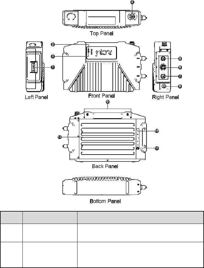
2.1 Host
Num. Item Description
1 Battery Buckle Toggle b uckle in th e dir ection of th e arr ow o f
battery buckle and pull out or insert the battery.
2 Operation Indicator
Operation st atus indic ation and the o peration
indicator turns to flickerin g (the freq uency is 1s)
and green if the host is operating properly.

3
Num. Item Description
3 RF Antenna
Interface
Used to c onnect RF a ntenna for signal
transmission and reception.
The interface type is the UHF interface.
4 Data Interface Used for the host debu gging and interc onnection
with center through IP network.
5 Palm Microphone
Interface
Connect palm microphone.
6 Power Button
Used to contro l power on an d off. Long pres s the
button for 1s to po wer on, and l ong pres s the
button for 3s to power off.
7 Backpack Hole Used for device installation in the backpack.
8 Electric Quantity
Button
Touch the batter y l evel b utton, an d the p resent
power level can be chec ked throug h po wer
indicator.
9 Indicator
10 Battery Supply power for the host.
4
2.2 Palm Microphone
4
5
6
7
8
23
1
9
10
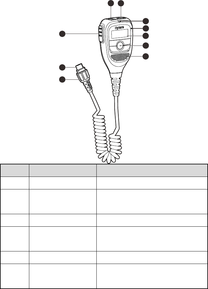
Num. Item Description
1 PTT Button Press the button to send a voice message.
2 Alarm Button Press the b utton to i nitiate a n emer gency
alarm.
3 Power Button Press the button to power on and off.
4 Indicator Operation status indic ation of palm
microphone.
5 MIC Voice can be transmitted through MIC.
6 Display Area Display status icons, ca lling informati on,
etc.

5
Num. Item Description
7 Keyboard Function keys.
8 Speaker The sound can be pla yed through the
speaker.
9 Aviation Plug Connect with the host.
10 Aviation Knob Fix the aviation.
6
3. Installation
3.1 Installation Requirements
Installation Position
The host can be installed inside the backpack, and on the operation platform as well.
3.2 Host Installation
The installation steps are as follows:
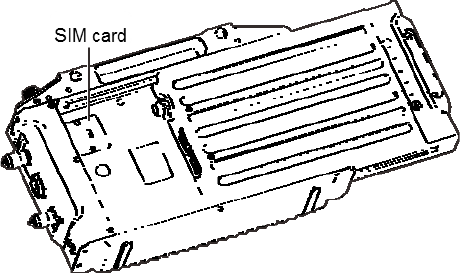
1. (Optional)SIM card Installation
If voice business through GSM link is in need, a SIM card can be installed in the
position as the figure below.
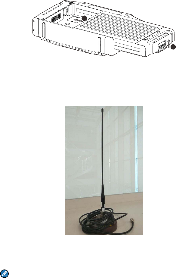
2. Battery installation in the back of the host
Aim the charging port to the main body, and then toggle the buckle in the direction of
battery buckle arrow. Next, don’t stop pushing the battery until it can’t be pushed any
further, and then loosen the battery buckle, as shown in the figure below.
7
2
1
3. Install the host as needed, such in a backpack or on a platform.
When the host is installed in a backpack, the backpack hole should be fixed with the
backpack using a screw.
4. The threaded end of sucker antenna should be inserted in the RF interface at the top
of the host, and then screw it in clockwise direction.
Note:
Please don’t power up the device when one carries it. When the device is operating, the
distance between a man and the antenna should be at least 2 meters. Our company
8
shall not take any responsibility if there were any consequece caused by operations
now following the above rules.
3.3 Check after Installation
After the whole insta llation process, the host can be po wered on. The proper
functioning of the host can be checked b y watching the status of the LED light on the
front panel. T he power indicator will be cons tantly red, and the oper ation indicator will
be green and flickering if the host functions properly. Besides, the operation status of
the host can be checked through palm microphone.

9
4. Basic Operation
4.1 Power on
Long press Power Button for 1s, and then the power indicator will be constantly green.
Comment
The palm microphone can power on the host if the two are connected.
4.2 Power off
Long press Power Button for 3s, and then the power indicator will extinguish.
4.3 GSM Link Building
Voice business through GSM link can be realized by using an external palm
microphone connecting with the host.
1. Connect the external palm microphone to the host.
2. Enter the GSM contact list, and then select the default GSM contact.
3. Press and hold PTT button, and then the GSM link can be built.
4.4 Switch Channel
When the external palm microphone is connected to the host, the 10 default alternative
channels can be switched to be the present channel through menu in the palm
microphone.
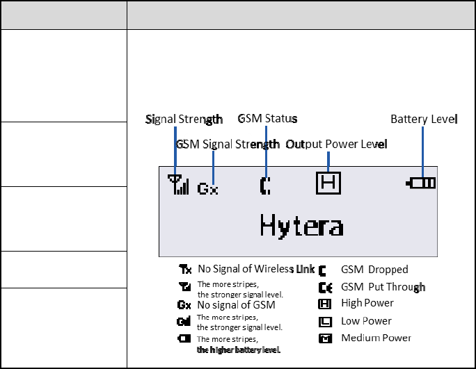
4.5 Host Information Query
When the external palm microphone connects to the host, the frequency, signal
strength, battery level and other information of the host can be checked through the
display screen of the palm microphone, as shown in the table below.
10
Operation Operation Method
Wireless Link
Signal Strength
Check
Enter the main interface of palm microp hone, as sho wn in
the figure below.
GSM Signal
Strength Check
GSM Link Status
Check
Power Level Check
Battery Level
Check

11
5. Fault Handling
Description Cause Analysis Solution
Power-On Failure
The battery i s not properl y
installed or in bad contact.
Check whether the
battery is correctly and
firmly installed is correct
and firm
Low battery.
Touch the battery display
button to check the
current battery level. In
case the battery runs out
of power, please charge
the battery first or
connect the external
power for power supply,
then try to power on.
Communication
failure between
E-pack100
The sendin g and rec eiving
frequency ar e not consisten t
between E-pack100.
Check whether the
frequency is consistent,
and please contact
dealer to reset the device
if necessary.
The work frequenc y po int is
disturbed by strong signal and
unable to transmit usefu l
signal.
Find the interference
source, and if unable to
shut down or stay away
from it, please apply for

12
Description Cause Analysis Solution
another channel
frequency.
Other E-pack100 have left the
communication coverage of
this E-pack100.
Confirm and return to the
communication
coverage.
E-pack100 antenna is in
abnormal connection
Check whether the
antenna is normally
connected.
Short communication
distance, and unclear
voice
The connection cable is
damaged and the signal
energy leaks.
Check the damage and
replace with new cable if
necessary.
Cable joint connected to the
antenna port is loose or
detached cable.
Check and tighten the
joint. Replace it with new
joint if necessary.
Transmit power is too low
Adjust the transmit power
to high power.
Cable is internal damaged.
Please replace it with a
new cable
Find the interference source,
and if unable to shut down or
stay away from it, please
apply for another channel
frequency.
Find the interference
source, and if unable to
shut down or stay away
from it, please apply for
another channel
frequency.
13
If the above method doesn’t solve your problem, or there are any other problems,
please contact the local dealer or our company for more technical support.

14
6. Maintenance and Cleaning
In order to ensure the good performance of the product and prolong its service life,
please familiarize with the following contents for better daily maintenance and cleaning
of this product.
Maintenance
Please do not use hard object puncture or scraping the product
Please do not store the product in an environment containing corrosive electronic
circuitry
Cleaning
Caution
Please power off the product and disconnect the power connection before
cleaning.
Please Use clean dry lint free or brush regularly to wipe the dust on the surface of
this product and the dust attached to the charging pole.
The buttons and case of this product are easily to become dirty. Clean with neutral
detergent and non-woven fabric. Please do not use detergents, alcohol, sprays or
petroleum preparations to clean the products so as to avoid damage to the surface
and case.
After cleaning, make sure that the product is completely dry, otherwise don't use it.

15
7. Accessories Purchase
If you want to purchase the main accessories of the product, please contact the dealer
or call our service hotline at 400-830-7020.
Caution
Please use the accessories specifi ed by o ur company. T he consequences
due to any use of unauthorized accessories shall be the responsibility of the
user himself.
16
8. Scope and Duration of Warranty
We promise that the product produced by our company can enjoy the warranty service
under the contract from the date of purchase if there is any occurrence of the defects in
material or manufacturing process under the condition of normal use, operation and
maintenance.