Hytera Communications EPOLE100F4 Digital WANET Repeater User Manual
Hytera Communications Corporation Limited Digital WANET Repeater
UserManual.wiki
>
Hytera Communications
>
EPOLE100F4 User Manual
>
User Manual
Contents
1.
User Manual
2.
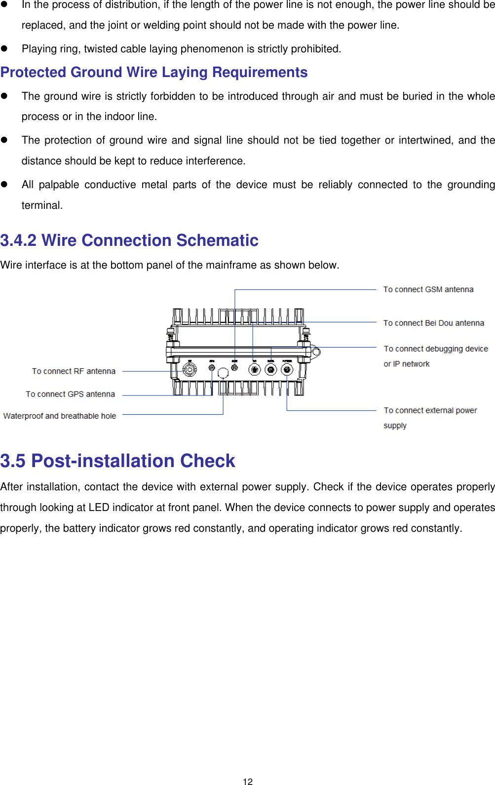
User manual
User Manual
Navigation menu
Upload a User Manual
Namespaces
Wiki Guide
HTML
PDF
Info
Views
User Manual
Discussion / Help
Navigation