Hytera Communications EPOLE100VHF Digital WANET Repeater User Manual
Hytera Communications Corporation Limited Digital WANET Repeater
User Manual
User Manual
Digital WANET Repeater
Preface
Thanks for your favor in our product. This manual provides guidance for you to use the product. To avoid
bodily injury and property loss caused by improper operations, please read the Safety Information
Booklet before using the product.
This manual is applicable to the following product:
E-pole Digital WANET Repeater

Icon Conventions
The following icons are available through this manual:
Caution: indicates situations that could cause damage to your product.
Note: indicates tips that can help you make better use of your product.
Copyright Information
Hytera is the trademark or registered trademark of Hytera Communications Corporation Limited (the
Company) in PRC and/or other countries or areas. The Company retains the ownership of its trademarks
and product names. All other trademarks and/or product names that may be used in this manual are
properties of their respective owners.
The product described in this manual may include the Company’s computer programs stored in memory
or other media. Laws in PRC and/or other countries or areas protect the exclusive rights of the Company
with respect to its computer programs. The purchase of this product shall not be deemed to grant, either
directly or by implication, any rights to the purchaser regarding the Company’s computer programs. Any
of the Company’s computer programs may not be copied, modified, distributed, decompiled, or
reverse-engineered in any manner without the prior written consent of the Company.
Disclaimer
The Company endeavors to achieve the accuracy and completeness of this manual, but no warranty of
accuracy or reliability is given. All the specifications and designs are subject to change without notice
due to continuous technology development. No part of this manual may be copied, modified, translated,
or distributed in any manner without the prior written consent of the Company.
We do not guarantee, for any particular purpose, the accuracy, validity, timeliness, legitimacy or
completeness of the Third Party products and contents involved in this manual.
If you have any suggestions or would like to learn more details, please visit our website at: http://www.
hytera.com.
FCC Regulations
Federal Communication Commission (FCC) requires that all radio communication products should meet
the requirements set forth in the above standards before they can be marketed in the U.S, and the
manufacturer shall post a RF label on the product to inform users of operational instructions, so as to
enhance their occupational health against exposure to RF energy.
FCC Statement
This equipment has been tested and found to comply with the limits for a Class B digital device, pursuant
to part 15 of FCC Rules. These limits are designed to provide reasonable protection against harmful
interference in a residential installation. This equipment generates and can radiate radio frequency
energy. If not installed and used in accordance with the instructions, it may cause harmful interference to
radio communications. However, there is no guarantee that interference will not occur in a particular
installation. Verification of harmful interference by this equipment to radio or television reception can be
determined by turning it off and then on. The user is encouraged to try to correct the interference by one
or more of the following measures:
Reorient or relocate the receiving antenna. Increase the separation between the equipment and
receiver.
Connect the equipment into an outlet on a different circuit to that of the receiver's outlet.
Consult the dealer or an experienced radio/TV technician for help.
Operation is subject to the following two conditions:
This device may not cause harmful interference.
This device must accept any interference received, including interference that may cause undesired
operation.
Note: Changes or modifications to this unit not expressly approved by the party responsible for
compliance could void the user's authority to operate the equipment.
Operational Instructions and Training Guidelines
To ensure optimal performance and compliance with the occupational/controlled environment RF energy
exposure limits in the above standards and guidelines, users should transmit not more than 50% of the
time and always adhere to the following procedures:
Antenna gain must not exceed 3.2dBi for DMR and 1.0dBi for GSM850 and 3.5 for PCS1900.
The antenna must be installed complying with the requirements of manufacturer or supplier, and it
must be at least 0.5 meters away from human body.
Compliance with RF Exposure Standards
Hytera's radio complies with the following RF energy exposure standards and guidelines:
United States Federal Communications Commission, Code of Federal Regulations; 47 CFR §
1.1307, 1.1310 and 2.1091
American National Standards Institute (ANSI) / Institute of Electrical and Electronic Engineers (IEEE)
C95. 1:2005; Canada RSS102 Issue 5 March 2015
Institute of Electrical and Electronic Engineers (IEEE) C95.1:2005 Edition
ISEDC Statement
This device complies with Innovation, Science and Economic Development Canada Compliance
license-exempt RSS standard(s). Operation is subject to the following two conditions:
This device may not cause harmful interference.
This device must accept any interference received, including interference that may cause undesired
operation.
Le présent appareil est conforme aux CNR d'Industrie Canada applicables aux appareils radio exempts
de licence. L'exploitation est autorisée aux deux conditions suivantes: (1) l'appareil ne doit pas produire
de brouillage, et (2) l'utilisateur de l'appareil doit accepter tout brouillage radioélectrique subi, même si le
brouillage est susceptible d'en compromettre le fonctionnement.
ISEDC Radiation Exposure Statement:
This device must be restricted to work related operations in an Occupational/Controlled RF
exposure Environment.
This equipment should be installed and operated with minimum distance 50cm between the
antenna & your body.
ISEDC exposition aux radiations:
Ce dispositif doit être limité aux opérations liées au travail dans un environnement
d'exposition RF professionnel/contrôlé.
Cet équipement doit être installé et utilisé avec un minimum de 50cm de distance entre le
antenne et votre corps.
EU Regulatory Conformance
As certified by the qualified laboratory, the product is in compliance with the essential requirements and
other relevant provisions of the Directive:
2014/53/EU
2006/66/EC
2011/65/EU
2012/19/EU
Please note that the above information is applicable to EU countries only.
The maximum antenna gain is 3.5dBi, which is caculated in the EIRP. The distance from observation
point to the antenna is 60cm.
Restrict use warning:
ATBECYCZDK
EEFIFRDEEL
HUIEITLVLT
LUMTNLPLPT
SKSIESSEUK
BGROHR
i
Contents
1. Checking Items in the Package ......................................................................................................... 1
2. Product Descriptions ......................................................................................................................... 2
3. Installation .......................................................................................................................................... 4
3.1 Installation Requirements ............................................................................................................... 4
3.2 Pre-Installation Tasks ..................................................................................................................... 5
3.3 Device Installation ........................................................................................................................... 6
3.4 Cables Installation......................................................................................................................... 11
3.5 Post-installation Check ................................................................................................................. 12
4. Basic Operations .............................................................................................................................. 13
4.1 Power on ....................................................................................................................................... 13
4.2 Power off ....................................................................................................................................... 13
5. Troubleshooting ............................................................................................................................... 14
6. Care and Cleaning ............................................................................................................................ 15
7. Optional Accessories ....................................................................................................................... 16
8. Scope and Duration of Warranty ..................................................................................................... 17
1
1. Checking Items in the Package
Please unpack carefully and check if all items listed below are received. If any item is missing or
damaged, please contact your dealer.
Name Qty Name Qty
Mainframe 1 DC Wire 1
AC Wire 1 Owner’s Manual 1
Note
All pictures in this manual are for reference only.
2
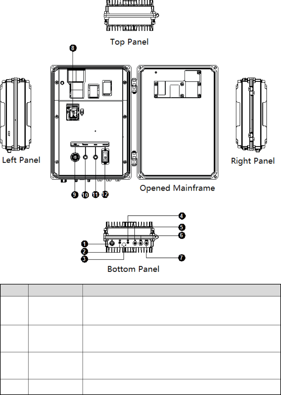
2. Product Descriptions
No Part Name Description
1 RF Antenna
Interface
Used to connect RF antenna for signal transmission and reception.
The interface type is the UHF interface.
2 GPS Antenna
Interface Connect GPS antenna, and used for transmit and receive SPG signal.
3 Waterproof and
breathable hole
Prevent the cavity from forming a vacuum and the lid can not be
opened.
4 GSM Antenna Connect GSM antenna, public network link as a backup link.

3
No Part Name Description
Interface
5 Bei Dou Interface The reserved interface is not developed for the time being.
6 Data Interface
For E-pole100 debugging.
Interconnect with center via IP network.
7 Power Interface
The device applies external power supply which supplies AC 100-240V
and DC 15V±10%.
DC power line is connected to DC input, and AC input is connected to
AC power line.
8 SIM Slot Install SIM card, and transmit data through GSM link.
9 Speaker Interface Connect speaker.
10 Power Indicator
Battery supply status indication. The power indicator grows red
constantly after power on.
11 Operation
Indicator
Indicates operation status. Under the normal operation state, the
indicator glows red constantly.
12 Backup Battery
Indicator
Control the opening and closing of the built-in standby battery of the
mainframe, and the standby power supply provides the voltage of the
10.8V.
4
3. Installation
3.1 Installation Requirements
Be sure to follow procedures below for proper installation.
Local Regulations and Norms
When installing the equipment, please follow the local regulations and norms.
Battery
Direct contact or indirect contact of high pressure and electricity through wet objects will bring
danger of electric shock.
Unstandardized and incorrect operations may cause accidents such as fire or electric shock.
It is strictly prohibited to wear conductive objects such as watches, bracelets, rings and so on
Special tools must be used in the operation of high voltage and alternating current.
When operating in a wet environment, water should be prevented from entering the equipment.
When operating in thunderstorm weather, in order to avoid lightning damages equipment, the
lightning protection work of the equipment should be done in time.
The power supply must be closed before the installation and removal of the equipment.
Before connecting the cable, the cable and the cable label must be confirmed.
The grounding operation must be completed before the device is connected to the power supply.
When it is found that the equipment is wet, or there is water or other liquids, please close the power
immediately.
Before installing the device, the power switch should be closed.
High Altitude Operation
Operations at more than 2 meters above the ground are all high altitude operations. At high altitude, the
notices below must be followed.
In the event of lightning, rain, snow, high winds above six levels, and dangerous conditions such as
dry rain in the steel pipe, the high altitude operation should be stopped.
At the scene of high altitude operation, the dangerous forbidden area should be drawn out, and the
marked sign should be set up, and the unrelated personnel shall be strictly prohibited.
The ground below the high altitude operation area is strictly forbidden to stack the scaffolding, the
springboard and other sundries. Ground personnel are strictly forbidden to stay or pass right below
the high altitude operation area.
Danger
5
High altitude operators should not throw objects from high altitude to the ground, nor throw objects
from the ground to the upper air. We should use strong cables, hanging baskets, elevated cars or
cranes to deliver objects.
Do a good job of safety protection, wear a helmet and fasten your seat belt correctly.
In cold areas, the cold defensive equipment should be worn before the high altitude operation.
Before the using a ladder, it should be confirmed that the ladder is not damaged, and can be used
by inspection. It is forbidden to be overweight when used.
Safety measures should be done in scenarios when the ladder is inclined more than 5m, vertical
height of vertical double foot ladder is more than 3m and operation is in dangerous environment.
High altitude operators should carry, use and place machinery and tools properly to prevent falling
on others.
Laughing and sleep in high altitude area is strictly prohibited in high altitude operation.
Personnel
The personnel engaged in the device operation must have basic knowledge of safety operation, and is
professional trained, and have corresponding job qualifications.
3.2 Pre-Installation Tasks
3.2.1 Installation Environment
Space Requirements
Keep at least 200mm space above.
Keep at least 500mm space below.
Keep at least 800mm space at right side.
Grounding Requirements
The device must be grounded first when install the device. The ground wire must be removed at last
when dismantled.
It is forbidden to damage the grounding conductors.
It is forbidden to operate the device where no ground wires are installed.
The device must be grounded permanently. Before operating the device, electrical connection must
be checked first to make sure that the device is grounded.
3.2.2 Tools Preparation
Before installation, please prepare the following tools as shown below.
6
Standard
Tools
Cross screwdriver, screwdriver, movable spanner, six-angle wrench, cross torque
screwdriver, dual wrench, rubber hammer, torque sleeve
Protective
Tools Antistatic wristband, seat belt, helmet, safety rope, antiskid gloves.
Cable Making
Tools Crimping pliers, stripping pliers, cutting pliers
Instrument
Tool Multimeter, tape measure, level ruler
Assistant
Tools
Fixed pulley, herringbone ladder, marking pen, impact drill, insulating tape, ribbon
(ultraviolet proof band), label, screw assembly, expansion screw assembly, tool knife,
hot air gun, waterproof tape
3.2.3 Materials Preparation
Before installation, please open the box and check the goods in accordance with the list of equipment to
ensure that the material is complete.
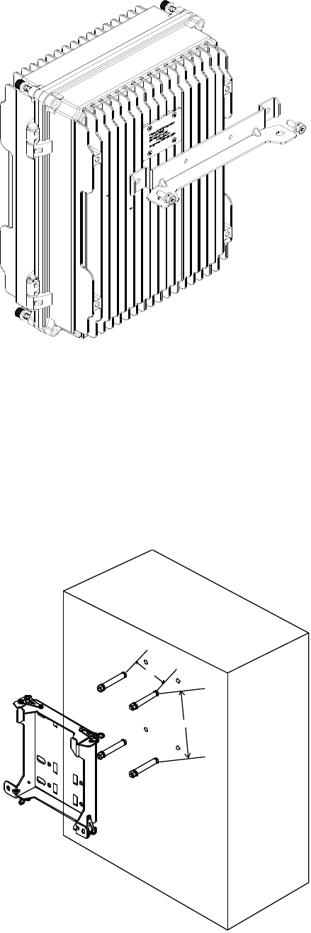
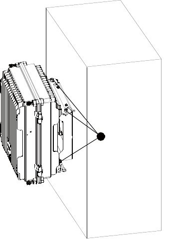
3.3 Device Installation
E-pole100 can adopts pole-mounted and wall-mounted type to install and user can choose according to
the actual needs.
The parts used in the installation process should be purchased separately. Please consult the
dealer or the sales staff of our company.
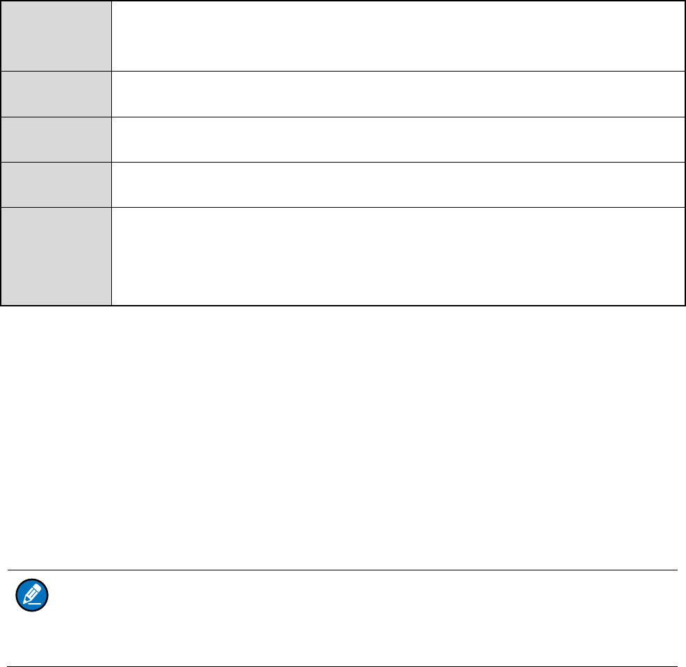
3.3.1 Bracket Introduction
Bracket components includes pole-mounted bracket components and wall-mounted bracket
components. The two both consists of bracket, four M3×8 bolts ○
2 and four silicone products ○
1.
Note
7
1
2
2
2
1
1
3.3.2 Pole-Mounted Installation
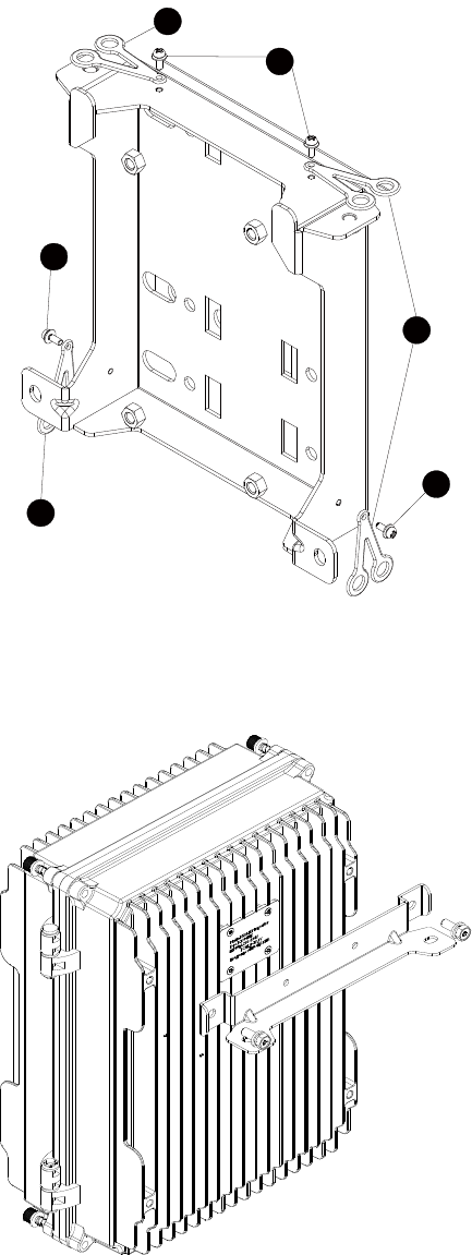
1. Use two M6×16 bolts to fix the bracket to the rear side of mainframe.
2. Use four M6×16 bolts to fix the pole-mounted bracket to the pole-mounted bracket components.
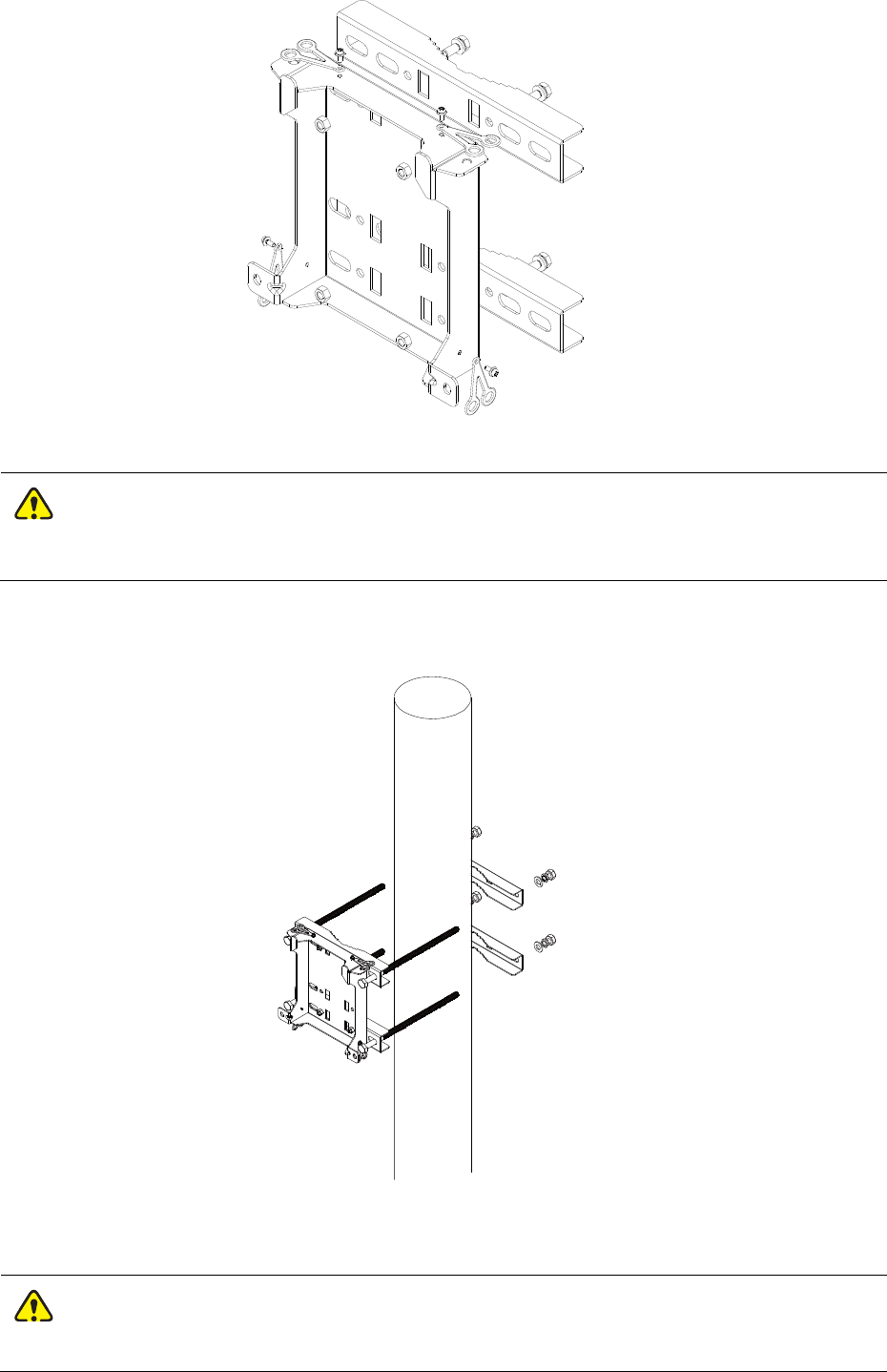
8
3. Mark the position of the pole-mounted bracket components on the pole.
The diameter of the holding rod should not exceed 180mm.
4. Use four M10×240 screw suite to fix pole-mounted bracket components and pole-mounted bracket
to pole.
5. Adopt the same method to install antenna bracket components, GPS antenna, Bei Dou antenna and
RF antenna.
The distance between pole-mounted bracket components and antenna bracket components
Caution
Caution
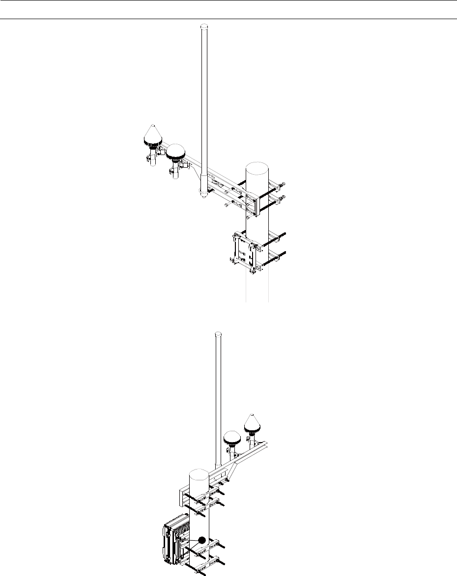
9
can be less than 200mm.
6. Fix the bracket of mainframe to pole-mounted bracket components with four M6×16 bolts ○
1.
1
3.3.3 Wall-mounted Installation
1. Use two M6×16 bolts to fix the bracket to the rear side of the mainframe.
10
2. Keep the wall-mounted bracket closely to the wall, level the installation position with a horizontal
ruler and mark the point with the marker pen.
3. Punch holes at the location and install the expansion bolt, and use the 4 M6x65 expansion screws
to fix the wall-mounted bracket on the wall.
4. The distance between the horizontal and vertical directions is 80mm and 145mm, respectively.
The distance between the horizontal and vertical directions is 80mm and 145mm, respectively.
145mm
80mm
5. Fix bracket of the mainframe to the wall-mounted components, and use four M6x16 bolts ○
1 to fix
it.
11
1
3.4 Cables Installation
3.4.1 Cable Laying Requirements
Cable placement needs to meet the required layout requirements in order to prevent inter signal interference.
Installation Requirement
When deploy cables, try to avoid sharp object or wall burr, if impossible, and then use a liner
protective cable.
When deploy cables, try to avoid heat source, or add insulation material between the heat source.
Binding Requirements
Similar cables should be tied up together.
The tied up cables should be closed to each other, flat, tidy and without skin damage.
When making the cable clasps, it should all face to the same direction. The cable in the same
position should be in the same level.
After finishing installing the cables, a label must be pasted at both cable ends, in the middle or cable
bending part.
Different types of cables are distributed separately. And intertwining or cross deployment is
forbidden.
Power Cable Laying Requirements
The position of the power line distribution should be in accordance with the requirements of the
engineering design drawings.
12
In the process of distribution, if the length of the power line is not enough, the power line should be
replaced, and the joint or welding point should not be made with the power line.
Playing ring, twisted cable laying phenomenon is strictly prohibited.
Protected Ground Wire Laying Requirements
The ground wire is strictly forbidden to be introduced through air and must be buried in the whole
process or in the indoor line.
The protection of ground wire and signal line should not be tied together or intertwined, and the
distance should be kept to reduce interference.
All palpable conductive metal parts of the device must be reliably connected to the grounding
terminal.
3.4.2 Wire Connection Schematic
Wire interface is at the bottom panel of the mainframe as shown below.
3.5 Post-installation Check
After installation, contact the device with external power supply. Check if the device operates properly
through looking at LED indicator at front panel. When the device connects to power supply and operates
properly, the battery indicator grows red constantly, and operating indicator grows red constantly.

13
4. Basic Operations
4.1 Power on
Connect the product to the external power supply, and the battery indicator glows red constantly.
Note
In order to make sure that the device can operate for a short time after a sudden power failure. It
is suggestible that put the built-in battery switch to ON position.
4.2 Power off
Disconnect the external power supply, and the battery indicator goes off. Make sure that built-in battery
switches to OFF.

14
5. Troubleshooting
Phenomena Analysis Solution
The product
cannot be
powered on.
Abnormal connection of power cord. Connect the power cord properly and
ensure secure connection.
Communication
failure between
E-pole100s,
and failure
between
E-pole100 and
E-pack100.
Problems with transceiver frequency
band configuration of system.
Check the frequency. Please contact
dealer if necessary.
The product encounters strong
interference signal.
Check the interference signal source. If
you cannot remove or bypass the
interference signal source, change the
frequencies.
Other E-pole100 or E-pack100 has left
the communication coverage of the
E-pole100.
Confirm and come back to the
communication coverage of E-pole100.
Abnormal connection of E-pole100
antenna. Check if antenna connection.
Short
communication
range or poor
audio.
The connection cable is damaged to
cause leakage of signal energy.
Check the cable. If necessary, replace
the cable with a new one.
The connector on the antenna cable may
get loose or even disconnected.
Check and secure the connector on the
antenna cable, or replace it if
necessary.
Tx Power is too low Set Tx power to high power.
Invisible damage may occur to the cable. Replace the cable with a new one.
The product encounters strong
interference signal.
Check the interference signal source. If
you cannot remove or bypass the
interference signal source, change the
frequencies.
If the above solutions cannot fix your problems, or you may have some other queries, please contact us
or your local dealer for more technical support.

15
6. Care and Cleaning
To guarantee optimal performance as well as a long service life of the product, please follow the tips
below.
Product Care
Do not pierce or scrape the product
Keep the product far away from substances that can corrode the circuit.
Please keep the product dry.
Please don’t put the product somewhere too hot. High temperature will shorten the life span of
electronic devices, damage battery, deform or melt some plastic parts.
Please don’t put the product somewhere too cold. When the temperature is high and above room
temperature, moisture inside the device will emerge and leads to damage to circuit board.
Product Cleaning
Caution
Disconnect the power supply from the product before cleaning.
Clean up the dust and fine particles on the product surface and charging piece with a clean and dry
lint-free cloth or a brush regularly.
Use neutral cleanser and a non-woven fabric to clean the keys and surface after long-time use. Do
not use chemical preparations such as stain removers, alcohol, sprays or oil preparations, so as to
avoid surface damage.
Make sure the product is completely dry before use.

16
7. Optional Accessories
Contact your local dealer for the optional accessories of the product.
Caution
Use the accessories specified by the Company only; otherwise, we shall not be liable for any
losses or damages arising out of use of unauthorized accessories.
17
8. Scope and Duration of Warranty
Our company promises that if there is any material or manufacturing process defects of the products
produced by us from the date of purchase under normal use, operation and maintenance conditions, can
enjoy the following provisions of warranty service.