Hytera Communications MD65XU1 Digital Mobile Radio User Manual
Hytera Communications Corporation Ltd. Digital Mobile Radio
User Manual
1
Preface
Thanks for your favor in our product. This manual is helpful for you to quickly know how to use the
product. Please refer to the corresponding Feature Book for detailed features and operations.
This manual is applicable to the following product:
MD65X Digital Mobile Radio
(X may represent 0,2, 5, 6 or 8)

2
Instructional Icons
: Indicates functions that are available on digital channel only.
: Indicates functions that are available on analog channel only.
Functions marked with no function icons are available on both analog and digital channels.
Disclaimer
The Company endeavors to achieve the accuracy and completeness of this manual, but no warranty of
accuracy or reliability is given. All the specifications and designs are subject to change without notice
due to continuous technology development. No part of this manual may be copied, modified, translated,
or distributed in any manner without the express written permission of us.
We do not guarantee, for any particular purpose, the accuracy, validity, timeliness, legitimacy or
completeness of the Third Party products and contents involved in this manual.
If you have any suggestions or would like to learn more details, please visit our website at:
http://www.hytera.com.
RF Radiation Information
This product must be restricted to operations in an Occupational/Controlled RF exposure Environments.
Users must be fully aware of the hazards of the exposure and able to exercise control over their RF
exposure to qualify for the higher exposure limits.
RF Radiation Profile
Radio Frequency (RF) is a frequency of electromagnetic radiation in the range at which radio signals are
transmitted. RF technology is widely used in communication, medicine, food processing and other fields.
It may generate radiation during use.
RF Radiation Safety
In order to ensure user health, experts from relevant industries including science, engineering, medicine
and health work with international organizations to develop standards for safe exposure to RF radiation.
These standards consist of:
United States Federal Communications Commission, Code of Federal Regulations; 47CFR part 2
sub-part J;
American National Standards Institute (ANSI)/Institute of Electrical and Electronic Engineers (IEEE)
C95. 1-1992;
Institute of Electrical and Electronic Engineers (IEEE) C95.1-1999;
3
International Commission on Non-Ionizing Radiation Protection (ICNIRP) 1998.
FCC Regulations
Federal Communication Commission (FCC) requires that all radio communication products should meet
the requirements set forth in the above standards before they can be marketed in the U.S, and the
manufacturer shall post a RF label on the product to inform users of operational instructions, so as to
enhance their occupational health against exposure to RF energy.
This device complies with part 15 of the FCC Rules. Operation is subject to the condition that this device
does not cause harmful interference.
The manufacturer is not responsible for any radio or TV interference caused by unauthorized
modifications to this equipment. such modifications could void the user's authority to operate this
equipment.
This equipment has been tested and found to comply with the limits for a Class B digital device, pursuant
to part 15 of the FCC Rules. These limits are designed to pro-vide reasonable protection against harmful
interference in a residential installation. This equipment generates, uses and can radi-ate radio
frequency energy and, if not in-stalled and used in accordance with the in-structions, may cause harmful
interference to radio communications. However, there is no guarantee that interference will not occur in
a particular installation. If this equip-ment does cause harmful interference to radio or television
reception, which can be determined by turning the equipment off and on, the user is encouraged to try to
correct the interference by one or more of the fol-lowing measures:
● Reorient or relocate the receiving antenna.
● Connect the equipment into an outlet on a circuit different from that to which the receiver is
connected.
● Consult the dealer or an experienced radio/ TV technician for help.
Operational Instructions and Training Guidelines
To ensure optimal performance and compliance with the occupational/controlled environment RF energy
exposure limits in the above standards and guidelines, users should transmit not more than 50% of the
time and always adhere to the following procedures:
Antenna gain must not exceed 5.5dBi for UHF or 5.5dBi for VHF.
The antenna installation must comply with the requirements of manufacturer or supplier, and it must
be 1.08 meter away from human body.
To ensure optimal performance and compliance with the occupational/controlled environment RF
energy exposure limits in the above standards and guidelines, users should transmit no more than
50% of the time and always adhere to the following procedures; and should transmit no more than

4
50% of the time, although the hardware support transmission up to 100% of the time in analog mode
and up to 50% in digital mode.
EU Regulatory Conformance
EU Regulatory Conformance
The equipment is in compliance with the essential requirements and other relevant provisions of the
Directive 1999/5/EC.
5
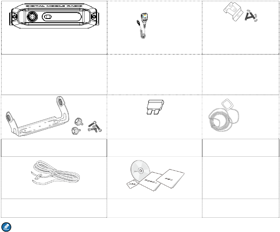
1. Items in the Package
Please unpack carefully and check that all items listed below are received. If any item is missing or
damaged, please contact your dealer.
Radio Unit Remote Speaker Microphone Hanger and Screws for
Remote Speaker
Microphone
Mounting Bracket Kit Fuse GPS Antenna
Power Cord Documentation Kit
Note:
The GPS antenna is the standard accessory for the MD65X with GPS feature. The frequency
band is marked on the label of antenna; if not, please refer to the label on the radio for frequency
band information.
If not particularly specified, the remote speaker microphone mentioned in this manual indicates
that in the item list.

6
2. Product Overview
2.1 Radio Unit
Caution:
GPS antenna connector is for MD65X mobile radio with GPS feature only.
Do not block the ventilation hole of the fan.
Clean the fan regularly.
Do not use stop the fan with hard objects such as screwdriver to avoid fan damage.
Do not touch the fan when it operates to avoid bodily injury.
2.2 Remote Speaker Microphone
For enhanced functionality, you may request your dealer to program the TK, P1 and P2 key as shortcut
to certain feature. You may refer to the corresponding Feature Book for feature details.
Caution: By default, the TK key short press is set as the programmed Emergency On key while
long press is set as the programmed Emergency Off key.
7
3. Installation
3.2 Instructions
Before you install the product in a vehicle, be sure to read the following instructions carefully:
The product operates with cathode-grounded power supply of 13.6V±15% only. Please check the
polarity and voltage of the power supply on the vehicle before you install the product.
Please check how long the screws will extend from the bottom surface of the product before
installation. Drill the mounting hole cautiously to avoid damage to the vehicle wiring and other parts.
Please connect Hytera supplied antenna and power cord to the product, before you install it in the
bracket. And make sure the antenna and power cord are dedicated for Hytera digital radios.
Install the product with Hytera supplied mounting bracket, to avoid product looseness in case of
accidents. The loose product may cause bodily injury.
Install the product in a location where it’s easy to reach the front panel controls.
Please make sure there’s sufficient space at the back of the product for wiring.
Be sure to use the fuse with the same specification for DC power cord upon replacement.
If another piece of equipment is nearby, such as a repeater, make sure there is at least 10 meters
between the antenna of this product and the antenna of that equipment.
3.3 Tools
Drill
Cross head screwdriver
Hex socket sleeve (for 4.8×20mm self-tapping screws assembling)
3.4 Operation
Follow the steps below to install the product:
1. Install the bracket in a location where it’s easy to operate the product.
2. Connect accessories such as the antenna and power cord to the product.
3. Slide the product into the properly mounted bracket and secure it using the locking knobs.
4. Install the remote speaker microphone hanger in a location where it can be reached conveniently.
5. Plug the remote speaker microphone connector into the microphone connector on the front panel,
but at first align the triangle index on the remote speaker microphone with the microphone
installation index on the microphone connector. Place the remote speaker microphone on the hanger
when you do not use it.
The assembly parts of the product are listed below:

8
No. Part Name No. Part Name
1 Radio Unit 8 Power Interface
2 Locking Knobs 9 Power Cord (black)
3 Mounting Bracket 10 Power Cord (red)
4 4.8×20mm Self-tapping Screws 11 Fuse
5 Remote Speaker Microphone 12 RF Antenna Connector
6 4×16mm Self-tapping Screws 13 GPS Antenna Connector
7 Remote Speaker Microphone Hanger / /
9
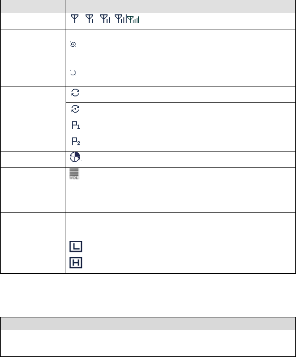
4. Indications
The LCD display and LED indicators on the remote speaker microphone indicate the operation status of
the radio.
4.2 LCD Icon
Icon Name Icon Display Product Status
RSSI Icon More bars indicate better signal strength.
GPS Icon
The GPS feature is enabled, and valid GPS data is
received.
The GPS feature is enabled, but no valid GPS data
is received.
Scan Icon
The radio is scanning.
The radio stays on a non-priority channel.
The radio stays on Priority Channel 1.
The radio stays on Priority Channel 2.
Roam Icon The radio is roaming.
Volume Icon More bars indicate higher volume.
Channel Icon CHXX Indicates the current channel. “XX” denotes the
channel number, such as “CH01”.
Zone Icon ZONEXX Indicates the current zone. “XX” denotes the zone
number, such as “ZONE01”.
TX Power Icon
Low power in current channel.
High power in current channel.
4.3 LED Indicator
LED Indication Product Status
The LED
indicator flashes Powering on.

10
LED Indication Product Status
green.
The LED
indicator glows
red.
Transmitting.
The LED
indicator glows
green.
Receiving.
The LED
indicator flashes
orange slowly.
Scanning or roaming.
The LED
indicator flashes
orange rapidly.
Emergency.
The LED
indicator glows
orange.
The call is established successfully and you can hold down the PTT key to talk.

11
5. Basic Operation
5.2 Powering On/Off
Method 1
Method 2
5.3 Adjusting the Volume
步骤 3 Press the key on the remote microphone speaker until the icon is shadowed.
步骤 4 Press the key to lower the volume and press the key to increase it.
5.4 Selecting a Zone
You can include a group of channels with the same property into a zone for convenient management.
The radio supports 64 zones, each of which consists of up to 16 channels.
To select a zone, do as follows:
步骤 1 Press the key on the remote microphone speaker until ZONEXX (e.g. ZONE01) is
shadowed.
步骤 2 Press the / key to select a zone.
5.5 Selecting a Channel
步骤 1 Press the key on the remote microphone speaker until CHXX (e.g. CH01) is shadowed.
步骤 2 Press the / key to select a channel.
If the Channel Notify feature is enabled by your dealer, the radio will play the channel number upon
channel switching.
5.6 Setting TX Power Level
This feature is to set the TX power level to high or low. High power can extend the signal coverage,
enabling you to communicate with farther radios. Generally, we recommend you to adopt low power for
battery saving. However, if you cannot communicate with radios located at a distant place with low
power, please select high power.
To set the TX power level, do as follows:

12
步骤 1 Press the key on the remote microphone speaker until the TX power level Icon (e.g. )
is shadowed.
步骤 2 Press the / key to switch power level.
13
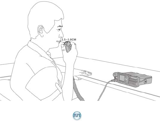
6. Initiating a Call
After the radio is powered on, you can make different kinds of calls. To ensure optimal volume of the
receiving radio, keep the microphone about 2.5 to 5 centimeters away from your mouth when
transmitting.
6.2 Calling on Digital Channel
You can initiate a private call, group call or all call (your radio must be programmed to allow you to use
the all call service) through the same operations on digital channel.
When calling back, the radio will make a call to the calling party in private call and all call (your radio
must be programmed to allow you to call back in an all call); but in group call, the radio will make a call to
all parties involved when calling back. Here takes the private call between Radio A and Radio B as
example:
1. Radio A and B select the same digital channel.
2. Radio A holds down the PTT key to initiate a call.
You may preset a regular private call/group call/all call contact for each digital channel via your
dealer.
3. By holding down the PTT key, Radio A can talk to the microphone when the LED indicator on the
radio glows red.
4. Radio A releases the PTT key to finish talking.
Radio A can hold down the PTT key to talk when the LED indicator on the radio is glowing orange.
When receiving, the LED indicator on the radio glows green.
5. Radio B can receive the call without any operation. When receiving, the LED indicator glows green.
6. Radio B can hold down the PTT key to talk when the LED indicator on the radio is glowing orange.

14
Note:
The Call Hold Time (the duration of LED indicator glowing orange) is preset by your dealer. If neither
party talks before this duration expires, the call will end.
6.3 Calling on Analog Channel (No Signaling)
On the analog channel without signaling, the calling operations are the same as that on the digital
channel. The difference is that the called parties are all the users on the channel, rather than the preset
contact for the channel.
Please refer to the corresponding Feature Book for calling operations on the analog channel with
signaling.
15
7. Feature Description
Available features of this radio are listed below. Please refer to the corresponding Feature Book for
details.
Feature Type Detailed Feature
Radio Features
Radio setting: Power Level, LED Indicator and Alert Tone
Convenient functionality: Shortcuts, One Touch Call and VOX
Security: Lone Worker
Rent
Audio Optimization
Positioning
Conventional Common
Features
Scan
Talk Around
Digital Features
Access management
7.2 Calling on Digital Channel
Basic voice services: Private Call and Group Call (See {0>数字信道呼
叫<}100{Calling on Digital Channel
in this manual)
7.3 Calling on Digital Channel
Auxiliary voice services: All Call (See {0>数字信道呼叫 <}100{Calling
on Digital Channel
in this manual) and Phone
Security
Supplementary services
Patented features
Mobility management
Analog Features
Access management
7.4 Calling on Analog Channel (No
Signaling)

16
Feature Type Detailed Feature
Voice services (See {0>模拟信道呼叫(无信令) <}100{>Calling on
Analog Channel (No Signaling)
in this manual)
Security
Signaling
Features Developed
with Third Party
API
Accessory Connector

17
8. Troubleshooting
Phenomena Analysis Solution
Power-on Failure. The power cord may be
disconnected. Properly connect the power cord.
During receiving,
the voice is weak,
discontinuous or
totally inactive.
Low volume level. Increase the volume via the remote speaker
microphone.
The antenna may be loosened
or improperly installed.
Turn off the product, re-install the antenna and
turn it on again.
The speaker may be blocked
or damaged.
Clean the surface of the speaker. If the
problem cannot be solved, contact your dealer
or authorized service center for inspection and
repair.
Unable to
communicate with
other members in
analog mode.
The frequency or signaling
does not match that of other
members.
Set your TX/RX frequency and signaling to the
same as that of other members.
You may be too far away from
the group members. Move towards other members.
In digital mode,
there’s RX
indication on the
radio, but unable to
communicate with
other members.
The digital carrier can be
received but cannot be
demodulated due to
inconsistent ID with that of
other members.
Sets the same ID of other members.
Irrelevant
communication or
noise is heard on
the channel.
You may be interrupted by
radios using the same
frequency.
Adjust the squelch level.
The radio may be set with no
signaling.
Set your radio with signaling to avoid
interference at the same frequency, and make
sure that all members share the same
signaling.
The noise is too You may be too far away from Move towards other members, and then try

18
Phenomena Analysis Solution
loud. other members. again.
You may locate in an
unfavorable position. For
example, your communication
may be blocked by high
buildings or frustrated in the
underground areas.
Move to an open and flat area, and restart the
radio to try again.
You may suffer from external
disturbance (such as
electromagnetic interference).
Stay away from equipment that may cause
interference.
No indication on
the LCD of the
remote speaker
microphone.
The LCD may fail to function
temporarily.
Restart the radio or reassemble the remote
speaker microphone.
GPS positioning
failure.
The GPS antenna may be
connected improperly. Properly connect the GPS antenna.
GPS signals cannot be
received due to unfavorable
position.
Move to an open and flat area to try again.
If the above solutions cannot fix the problems, or there are other questions, please contact Hytera or the
dealer for more technical support.

19
9. Care and Cleaning
To guarantee optimal performance as well as a long service life of the product, please follow the tips
below.
Product Care
Do not pierce or scrape the product.
Keep the product far away from substances that can corrode the circuit.
Do not hold the product by its antenna or earpiece cable directly.
Attach the accessory connector cover when the accessory is not in use.
Product Cleaning
Caution: Turn off the product and disconnect the power supply before cleaning.
Clean up the dust and fine particles on the product surface and charging piece with a clean and dry
lint-free cloth or a brush regularly.
Use neutral cleanser and a non-woven fabric to clean the keys and front case after long-time use. Do
not use chemical preparations such as stain removers, alcohol, sprays or oil preparations, so as to
avoid surface case damage.
Make sure the product is completely dry before use.
20
10. Optional Accessories
The following items are the main optional accessories for the radio. For more information of other
accessories, please consult your local dealer.
Caution: Use the accessories specified by Hytera only. If not, the Company shall not be liable for
any loss or damage arising out of use of unauthorized accessories.
Accessory Type Model/Name
Power Supply PS22002 Vehicle Power Supply (220W, backup power applicable)
Audio SM09D1 External Speaker
Cable
PC37 10-Pin Connector Programming Cable (USB port)
PC47 Programming Cable (USB port)
PC49 Back-to-back Data Cable
Others Omni-directional Antenna