Hytera Communications MD78XGV3 DIGITAL MOBILE RADIO User Manual
Hytera Communications Corporation Limited DIGITAL MOBILE RADIO
User manual
Preface
Thanks for your favor in our product. This manual is helpful for you to quickly know how to use the
product. For detailed features and operations, please refer to the Feature Book along with the product.
This manual is applicable to the following product:
MD78X/MD78XG Digital Mobile Radio
(X may represent 2, 5, 6 or 8)

Instructional Icons
:Indicates functions that are available on digital channel only.
:Indicates functions that are available on analog channel only.
Functions marked with neither the above icons are available on both analog and digital channels.
Disclaimer
Hytera Communications Corporation Limited (the Company) endeavors to achieve the accuracy and
completeness of this manual, but no warranty of accuracy or reliability is given. All the specifications and
designs are subject to change without notice due to continuous technology development. No part of this
manual may be copied, modified, translated, or distributed in any manner without the express written
permission of us.
We do not guarantee, for any particular purpose, the accuracy, validity, timeliness, legitimacy or
completeness of the Third Party products and contents involved in this manual.
If you have any suggestions or would like to learn more details, please visit our website at:
http://www.hytera.com.
RF Radiation Information
This product must be restricted to operations in an occupational/controlled RF exposure environment.
Users must be fully aware of the hazards of the exposure and able to exercise control over their RF
exposure to qualify for the higher exposure limits.
RF Radiation Profile
Radio Frequency (RF) is a frequency of electromagnetic radiation in the range at which radio signals are
transmitted. RF technology is widely used in communication, medicine, food processing and other fields.
It may generate radiation during use.
RF Radiation Safety
In order to ensure user health, experts from relevant industries including science, engineering, medicine
and health work with international organizations to develop standards for safe exposure to RF radiation.
These standards consist of:
United States Federal Communications Commission, Code of Federal Regulations; 47CFR part 2
sub-part J;
American National Standards Institute (ANSI)/Institute of Electrical and Electronic Engineers (IEEE)
C95. 1-1992;
Institute of Electrical and Electronic Engineers (IEEE) C95.1-1999;
International Commission on Non-Ionizing Radiation Protection (ICNIRP) 1998;
FCC Regulations
Federal Communication Commission (FCC) requires that all radio communication products should meet
the requirements set forth in the above standards before they can be marketed in the U.S, and the
manufacturer shall post a RF label on the product to inform users of operational instructions, so as to
enhance their occupational health against exposure to RF energy.
Warning
This DIGITAL MOBILE RADIO generates RF electromagnetic energy during transmit mode. This radio is
designed for and classified as “Occupational Use Only”.
Operational Instructions and Training Guidelines
To ensure optimal performance and compliance with the occupational/controlled environment RF energy
exposure limits in the above standards and guidelines, users should transmit not more than 50% of the
time and always adhere to the following procedures:
Antenna gain must not exceed 5dBi for UHF.
The antenna installation must comply with the requirements of manufacturer or supplier, and it must
be 0.6 meter away from human body.
EU Regulatory Conformance
As certified by the qualified laboratory, the product is in compliance with the essential requirements and
other relevant provisions of the Directive 2014/53/EU.
Please note that the above information is applicable to EU countries only.

Contents
1. Items in the Package .......................................................................................................................... 1
2. Product Overview ............................................................................................................................... 2
2.1 Front Panel ..................................................................................................................................... 2
2.2 Rear Panel ...................................................................................................................................... 3
2.3 Programmable Keys ....................................................................................................................... 3
3. Before Use .......................................................................................................................................... 4
3.1 Instructions ..................................................................................................................................... 4
3.2 Installation ....................................................................................................................................... 4
4. Status Indication ................................................................................................................................ 7
4.1 LCD Icon ......................................................................................................................................... 7
4.2 LED Indicator .................................................................................................................................. 8
5. Menu Navigation ............................................................................................................................... 10
6. Basic Operations .............................................................................................................................. 11
6.1 Powering On/Off ........................................................................................................................... 11
6.2 Adjusting the Volume .................................................................................................................... 11
6.3 Selecting a Zone ........................................................................................................................... 12
6.4 Selecting a Channel ...................................................................................................................... 12
6.5 Inputting via Keypad ..................................................................................................................... 12
6.6 Managing the Contacts ................................................................................................................. 13
7. Call Service ....................................................................................................................................... 14
7.1 Private Call .............................................................................................................................. 14
7.2 Group Call ............................................................................................................................... 15
7.3 Call on Analog Channel (No Signaling) ................................................................................... 16
7.4 Emergency Call ............................................................................................................................ 16
8. Message Service ........................................................................................................................ 17
9. Troubleshooting ............................................................................................................................... 18
10. Care and Cleaning .......................................................................................................................... 20
11. Optional Accessories ..................................................................................................................... 21
12. PMR ................................................................................................................................................. 22
13. RF radiation safety warnings and the following: ......................................................................... 23
1
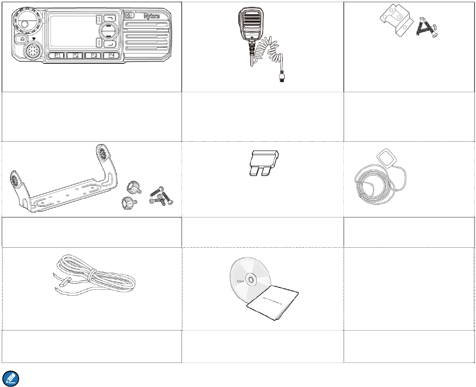
1. Items in the Package
Please unpack carefully and check that all items listed below are received. If any item is missing or
damaged, please contact your dealer.
Radio Unit Palm Microphone Microphone Hanger and
Screws
Mounting Bracket Kit Fuse GPS Antenna
Power Cord Documentation Kit
Note:
The GPS antenna is the standard accessory for the MD78XG. The descriptions related to the
GPS feature in this manual are applicable to MD78XG only
You need to purchase a palm microphone with keypad for inputting the alias, ID or text message.
For details, please go to “Optional Accessories” in this manual .
2
2. Product Overview
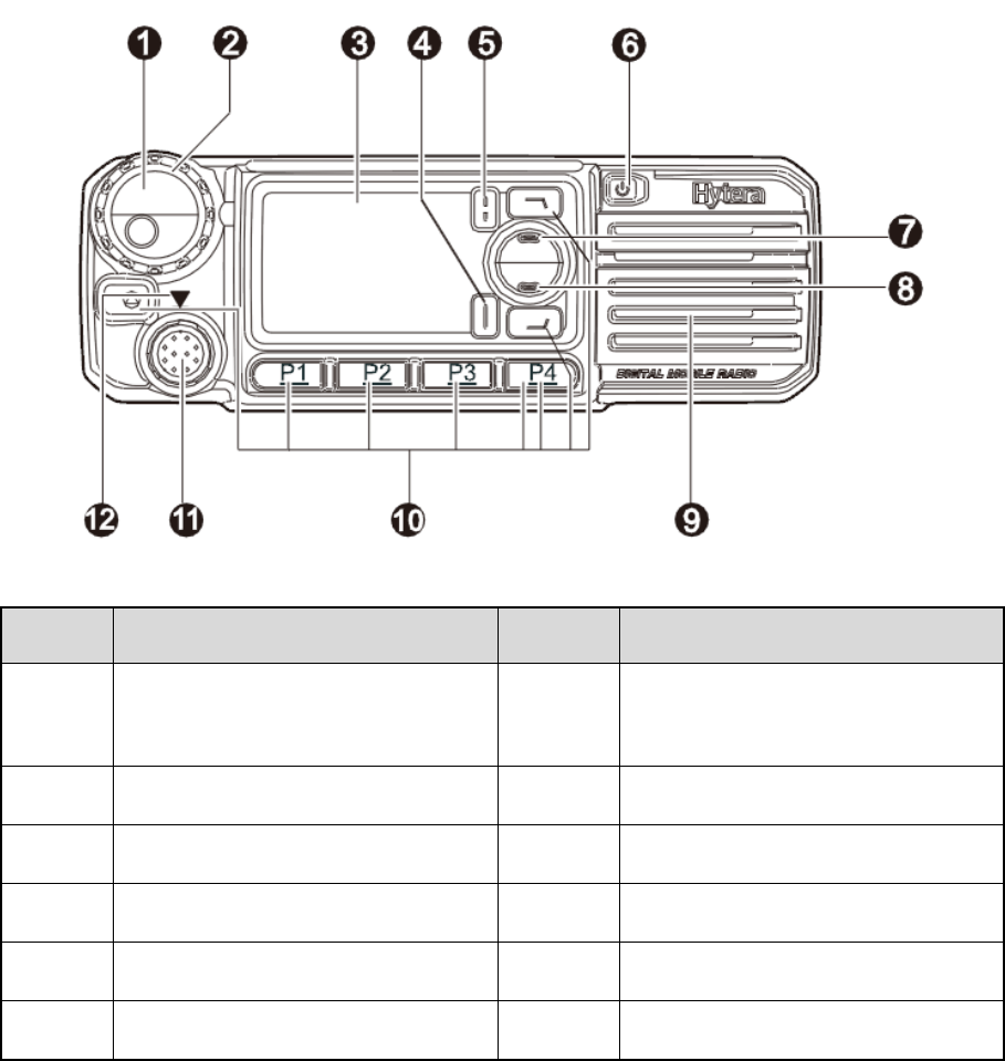
2.1 Front Panel
No. Part Name No. Part Name
1 Volume Control/Channel Selector
Knob 7 Up Key
2 LED Indicator 8 Down Key
3 LCD Display 9 Speaker
4 OK/Menu Key 10 Programmable Keys
5 Back Key 11 Microphone Connector
6 Power On/Off Key 12 Microphone Installation Index
3
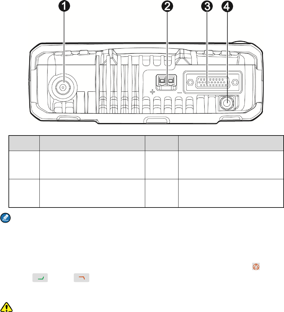
2.2 Rear Panel
No. Part Name No. Part Name
1 RF Antenna Connector (BNC
female) 3 Accessory connector
2 Power Inlet 4 GPS Antenna Connector (SMA
female)
Note: The GPS antenna connector is only available for MD78XG Mobile Radio.
2.3 Programmable Keys
For enhanced convenience, you may request your dealer to program the seven keys (TK( ), P1, P2,
P3, P4, P5( ) and P6( )) as shortcuts to the functions introduced in the Owner’s Manual. Please
refer to the corresponding Feature Book for more details.
Caution: The TK is programmed with emergency feature by default (short press: Emergency On;
long press: Emergency Off). It is programmable by your dealer. Short press of the P5 key is programmed
with the Contact List feature, and short press of the P6 key programmed with the Home Screen feature.
4
3. Before Use
3.1 Instructions
Before you install the radio in a vehicle, be sure to read the following instructions carefully:
The radio must work with a 13.6V ± 15% negative ground electrical system only. And ensure to check
the ground polarity and voltage of the vehicle power supply prior to installation.
Check how long the screws will extend from the bottom surface of the radio before installation. Drill
the mounting hole cautiously to avoid damage to the vehicle wiring and other parts.
Connect the antenna and power cord to the radio, before you install it in the bracket. And make sure
the antenna and power cord are dedicated for Hytera digital radios.
Install the radio with Hytera supplied mounting bracket, to avoid radio looseness in case of accidents.
The loose radio may cause bodily injury.
Install the radio in a location where it’s easy to reach the front panel controls.
Keep sufficient clearance at the back of the radio for wiring.
Be sure to use the fuse with the same specification for DC power cord upon replacement.
If there are any other device in the vicinity of this radio, the distance between the antenna of this radio
and the antenna of such RF device shall be no less than 10 meters.
3.2 Installation
Installation Tools
Electric drill
Cross head screwdriver
Hex socket sleeve (for 4.8×20mm self-tapping screws)
Installation Procedure
To install the radio, do as follows:
1. Install the bracket in a location where it’s easy to operate the radio.
2. Connect accessories such as the antenna and power cord to the radio.
3. Slide the radio into the properly mounted bracket and secure it using the locking knobs.
4. Install the microphone hanger in a location where it can be reached conveniently.
5. Plug the palm microphone into the radio, but at first align the triangle index on the palm microphone
with the microphone installation index. Place the palm microphone on the hanger when you do not
5
use it.
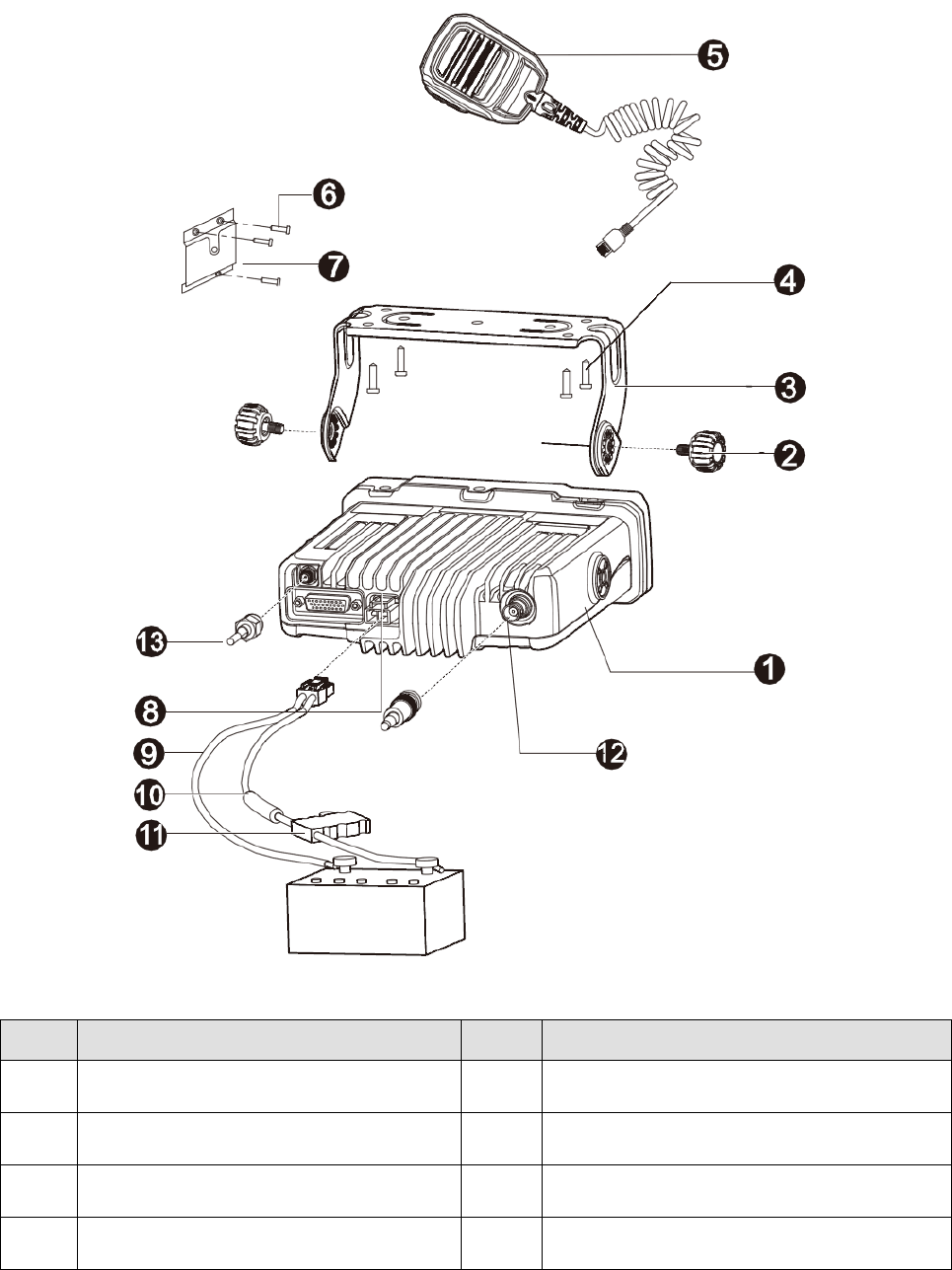
The parts of the radio are illustrated below:
No. Part Name No. Part Name
1 Radio Unit 8 Power Inlet
2 Locking Knobs 9 Power Cord (black)
3 Mounting Bracket 10 Power Cord (red)
4 4.8×20mm Self-tapping Screws 11 Fuse

6
No. Part Name No. Part Name
5 Palm Microphone 12 RF Antenna Connector
6 4×16mm Self-tapping Screws 13 GPS Antenna Connector
7 Palm Microphone Hanger / /
7
4. Status Indication
4.1 LCD Icon
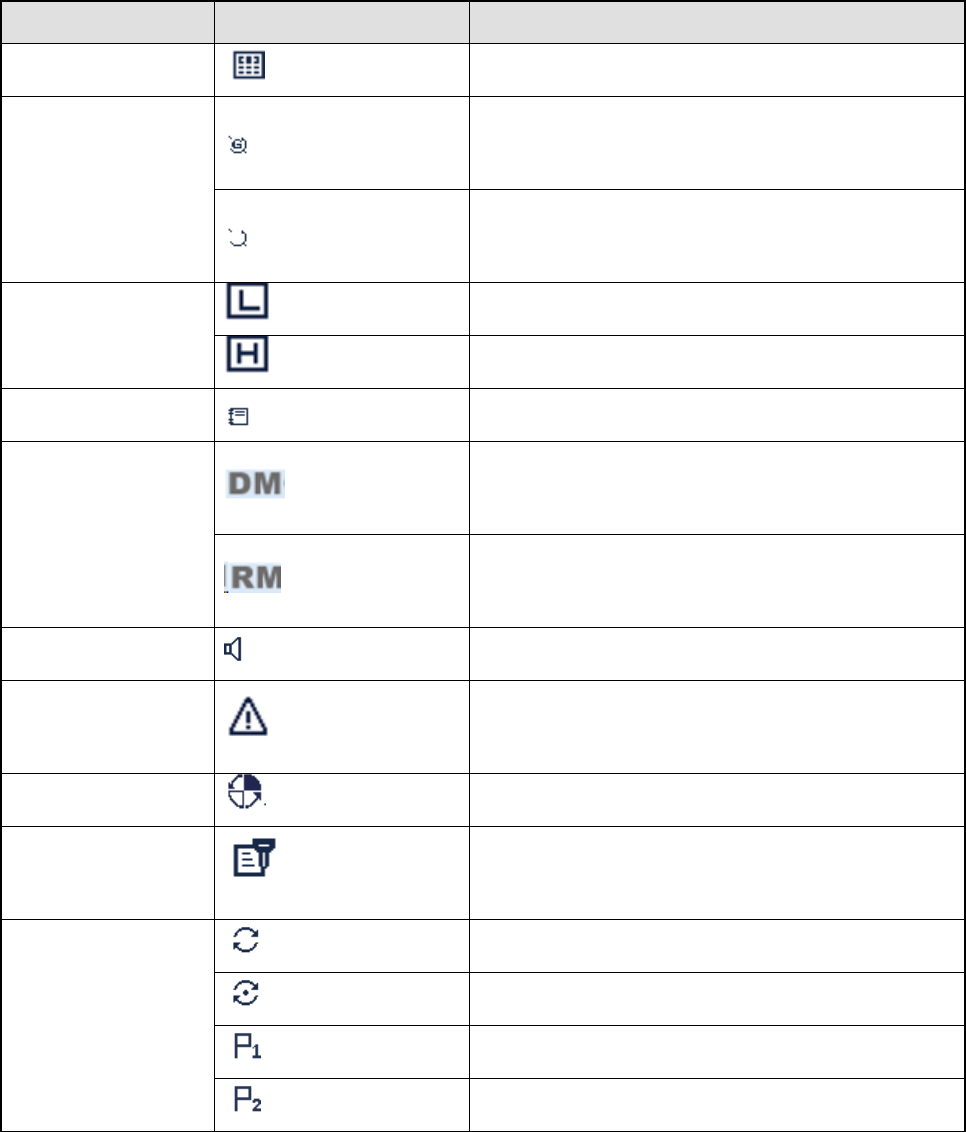
Name Icon Radio Status
DTMF Keypad Icon The DTMF keypad is enabled.
GPS Icon
The GPS feature is enabled, and valid GPS data is
received.
The GPS feature is enabled, but no valid GPS data
is received.
TX Power Icon
Low TX power for the current channel.
High TX power for the current channel.
Work Order Icon One or more new work orders are received.
Operation Mode
Icon
Direct Mode: Under this mode, the radio
communicates with other radios directly.
Repeater Mode: Under this mode, the radio
communicates with other radios via a repeater.
Monitor Icon The Monitor feature is enabled.
Emergency Icon The Emergency mode (except secret emergency)
is activated or an emergency alarm is received.
Roam Icon The radio is roaming.
Scrambler/Encrypt
Icon The Scrambler/Encrypt feature is enabled.
Scan Icon
The radio is scanning.
Scanning stays on a non-priority channel.
Scanning stays on Priority Channel 1.
Scanning stays on Priority Channel 2.
8
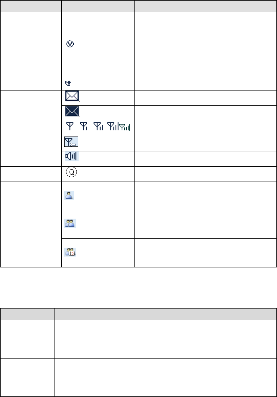
Name Icon Radio Status
VOX Icon The VOX feature is enabled.
Missed Call Icon Missed call(s).
Message Icon
Unread message(s).
Inbox is full.
RSSI Icon More bars indicate better signal strength.
Knob Operation
Mode Icon
The knob is used for channel selection currently.
The knob is used for volume control currently.
LQO Icon The LQO feature is enabled.
Call/Contact Icon
Indicates Private Call during a call.
Indicates Private Contact in the contact list.
Indicates Group Call during a call.
Indicates Group Contact in the contact list.
Indicates All Call during a call.
Indicates All Call Contact in the contact list.
4.2 LED Indicator
LED Indication Radio Status
The LED
indicator flashes
green
Powering on.
The LED
indicator glows
red
Transmitting.

9
LED Indication Radio Status
The LED
indicator glows
green
Receiving.
The LED
indicator flashes
orange slowly
Scanning or Roaming.
The LED
indicator flashes
orange rapidly
Emergency.
The LED
indicator glows
orange
Call hung. During a call, you can hold down the PTT key to talk to the other party
before the call hang time expires.
Note: Unless otherwise specified, the PPT key mentioned in this manual indicates that of the palm
microphone.
10
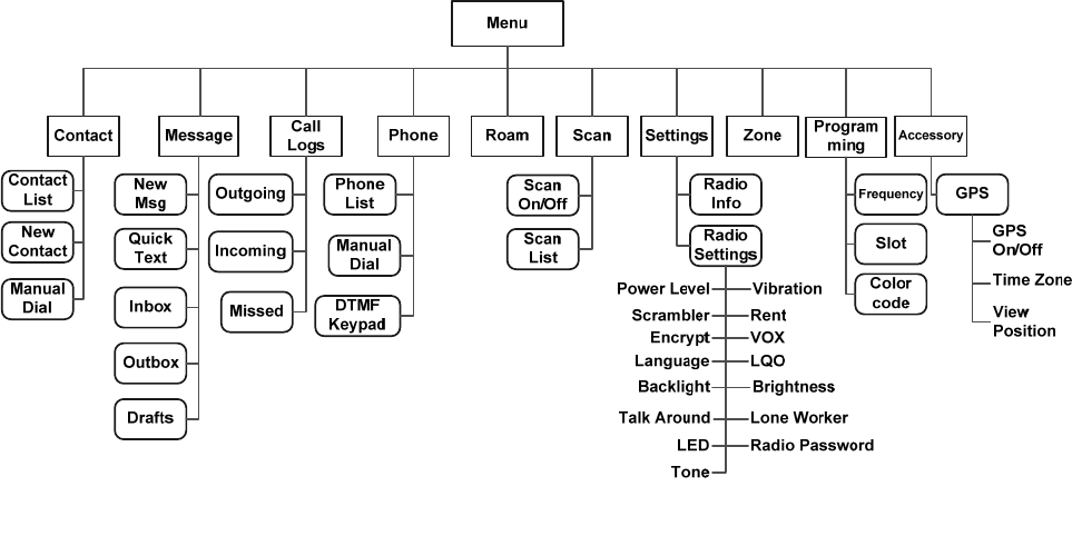
5. Menu Navigation
The following diagram outlines the menu structure of the radio. You can personalize menu option
displayed in the radio via your dealer.
To select and confirm the options shown in the menu, press the Menu key and then press the Up/Down
key to select the appropriate option, finally press the OK key. This manual only describes the paths to
the menus in terms of menu operations, for example, to access the contact list, go to “Contact -> Contact
List”.
The radio supports menu reset function. If you do not operate the menu for a preset time period
configured by the dealer, the radio will automatically return to the home screen. You may request the
dealer to change the auto reset time or disable the feature.
11
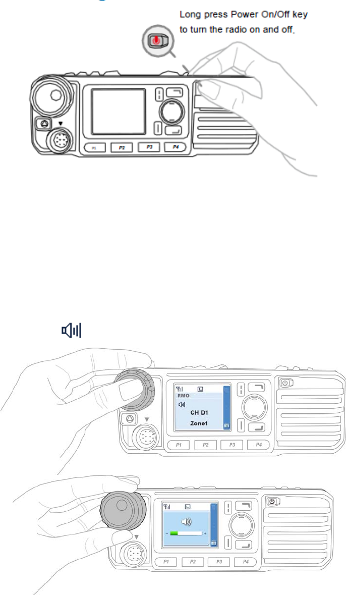
6. Basic Operations
6.1 Powering On/Off
6.2 Adjusting the Volume
You can adjust the volume of output voice, side tone and group notification tone by rotating the Volume
Control Knob. For other tones, the volume will be configured by the dealer.
Press the Volume Control/Group Call Selector Knob to switch the radio to volume adjustment mode
(the radio displays the icon ), and then rotate the knob to adjust the volume.
12
6.3 Selecting a Zone
A zone is a group of channels exhibiting the same property, which is programmed by your dealer
and can facilitate convenient management over the channel. The radio supports up to 64 zones, each
with a maximum of 16 channels. You may select a zone through any of the following methods:
Via the menu: Go to the menu “Zone”, then use the Up/Down key to select the appropriate zone
and press the OK key to confirm.
Via the programmable key: You may quickly toggle to the appropriate zone by pressing the
programmed Zone Up or Zone Down key.
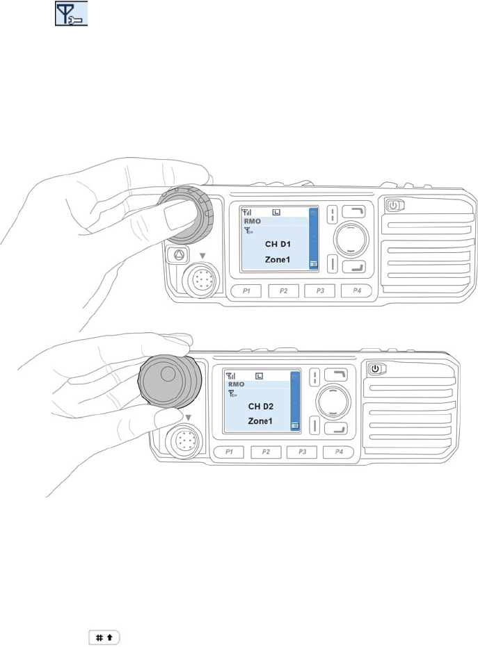
6.4 Selecting a Channel
Press the Volume Control/Channel Selector knob to switch the radio to channel selection mode (the
radio displays the icon ), and then rotate the knob to select the appropriate channel. You can also
switch to the designated channel by pressing the programmed Preset Channel key preset by your
dealer.
If the Channel Notify feature is enabled, you will hear the corresponding channel number when switching
to any channel.
6.5 Inputting via Keypad
You can input alias, call numbers and messages via the keypad on the palm microphone.
To switch input method:

13
To input special characters:
To input space:
Note: If not particularly specified, the keypad mentioned in this manual indicates that of the palm
microphone with keypad.
6.6 Managing the Contacts
You can manage the contacts via the “Contact” menu.
6.6.1 Contact List
The Contact List is used to save information of private call contacts. You can access the “Contact List”
menu via the “Contact” menu or by pressing the programmed Contact List key.
In the “Contact List” menu, you can view the contact information, edit or delete private contacts. You can
send to a private call contact the following commands: Alert Call, Radio Check, Remote Monitor, Radio
Enable or Radio Disable.
6.6.2 New Contact
You can add and save a new contact to the contact list. The ID and alias of each contact must be unique.
Note: Except for adding a new contact, you can also save the numbers in Call Logs, ReDial List and
BackDial List into the contact list.
14
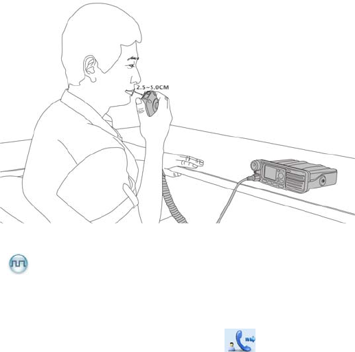
7. Call Service
After the radio is powered on, you can make and receive calls. To ensure optimal volume of the
receiving radio, keep the palm microphone about 2.5 to 5 centimeters away from your mouth when
speaking.
7.1 Private Call
7.1.1 Initiating a Private Call
When initiating a private call, the radio will display the icon . You can make a private call through
the following ways:
Preset Contact
In the home screen, hold down the PTT key on the palm microphone to initiate a Private Call to the
Private Call contact preset for the current channel.
You may request your dealer to preset a regular Private Call contact, Group Call contact or an All Call
contact for each digital channel.
Contact List or Call Log
Step 1 Go to “Menu -> Contact” or “Menu -> Call Logs” and access the “Contact List” submenu.
Step 2 Use the Up/Down key to select an appropriate contact.
Step 3 Hold down the PTT key to initiate a Private Call.
Manual Dial
Step 1 Go to “Menu -> Contact -> Manual Dial”.
Step 2 Input a Private Call number you want to call via the keypad.
Step 3 Hold down the PTT key to initiate a Private Call.

15
Note:
If both the Private Call Manual Dial and Group Call Manual Dial are available, you can press
to switch between the two dialing methods, and the radio will display the call type (private
call ID/ group call ID).
If the Default Numeric Key Selection feature is enabled by your dealer, you can enter a private call
number in the home screen, and then press the PTT key to transmit the call. However, if the
DTMF keypad is enabled, the number entered in the home screen is a phone number. You can
dial the private call number through the menu “Manual Dial” only.
7.1.2 Receiving and Responding to a Private Call
After receiving a private call, the radio will display the icon , then you can listen without any
operation. You can hold down the PTT key to call back within the preset time. If you do not respond to it, the
radio will provide appropriate indications.
7.2 Group Call
7.2.1 Initiating a Group Call
When initiating a group call, the radio will display the icon . You can make a group call through the
following ways and the operation is similar to Initiating a Private Call.
Preset Contact
In the home screen, hold down the PTT key on the palm microphone to initiate a Group Call to the Group
Call contact preset for the current channel.
Contact List
Step 1 Go to “Menu -> Contact -> Contact List”.
Step 2 Use the Up/Down key to select an appropriate contact.
Step 3 Hold down the PTT key to initiate a Group Call.
Manual Dial
Step 1 Go to “Menu -> Contact -> Manual Dial”).
Step 2 Input a Group Call number you want to call via the keypad.
Step 3 Hold down the PTT key to initiate a Group Call.

16
7.2.2 Receiving and Responding to a Group Call
After receiving a group call, the radio will display the icon . You can hold down the PTT key to call
back within the preset time.
7.3 Call on Analog Channel (No Signaling)
On an analog channel, you can hold down the PTT key and talk to the microphone to transmit, and
release the PTT key to receive.
7.4 Emergency Call
In case of an emergency, you can use this feature to ask for help from your companion or the control
center. The Emergency Call has the highest priority which can terminate the ongoing calls with lower
priorities on the current channel. You can make an emergency call even when your radio is transmitting
or receiving.
This feature needs to be configured and enabled by your dealer. Please refer to the corresponding
Feature Book for details.

17
8. Message Service
This feature enables you to edit and send a new message, to directly send a quick text message and to
forward the messages in the Inbox, Outbox and Drafts.
Sending a Message
Step 1 Go to “Menu -> Message -> New Msg” to enter the relevant interface.
Step 2 Type the text and then press the OK key. Save it to Drafts, or send it to a private call contact or
a group call contact.
Step 3 Select the contact or input the contact number manually.
Step 4 Press the OK key to send the message. When the message is sent successfully, the prompt
“Send Success!” will appear on the LCD.
Quick Text
The radio supports quick text message preset by your dealer. You can directly send the message or edit
it prior to sending.
Inbox
The radio saves the received messages into the Inbox and marks every message with a corresponding
icon to indicate its status.
: Read message.
: Unread message.
When the Inbox is full, the radio will display the icon , and the earliest message will be overwritten
by the latest one automatically.
Outbox
The radio saves the sent messages into the Outbox and marks every message with a corresponding
icon to indicate its status.
: The message is sent successfully.
: The message is not sent successfully. In this case, you can resend it.
When the Outbox is full, the earliest message will be overwritten by the latest one automatically.
Drafts
The radio saves the edited messages into the Drafts. When the Drafts is full, the earliest message will be
overwritten by the latest one automatically. After the message in the Drafts is sent successfully, it will be
removed from the Drafts and be saved into the Outbox. If not sent successfully, the message will be
saved into the Drafts and the Outbox.

18
9. Troubleshooting
Phenomena Analysis Solution
The radio fails to
power on.
The power cord may be
disconnected. Connect the power cord properly.
During receiving,
the voice is weak,
discontinuous or
totally inactive.
The volume level may be low. Increase the volume by rotating the Volume
Control Knob.
The antenna may be loosened
or improperly installed. Power off the radio and reattach the antenna.
The speaker may be blocked
or damaged.
Clean the surface of the speaker. If the
problem cannot be solved, contact your dealer
or our authorized service center for inspection
and repair.
You cannot
communicate with
other members in
analog mode.
The frequency or signaling may
not match that of other
members.
Set your TX/RX frequency and signaling to the
same as that of other members.
You may be too far away from
the group members. Move towards other members.
In digital mode,
there’s RX
indication on the
radio, you cannot
communicate with
other members.
The digital carrier may be
received but may not be
demodulated due to
inconsistent ID with that of
other members.
Sets the same ID of other members.
Irrelevant
communication or
noise is heard on
the channel.
You may be interrupted by
radios using the same
frequency.
Adjust the squelch level.
The radio may be set with no
signaling.
Set your radio with signaling to avoid
interference at the same frequency, and make
sure that all members share the same
signaling.

19
Phenomena Analysis Solution
The noise is too
loud.
You may be too far away from
other members.
Move towards other members, and restart the
radio to try again.
You may locate in an
unfavorable position. For
example, your communication
may be blocked by high
buildings or frustrated in the
underground areas.
Move to an open and flat area, and restart the
radio to try again.
You may suffer from external
disturbance (such as
electromagnetic interference).
Stay away from equipment that may cause
interference.
You cannot use the
keys.
The keypad may fail to function
temporarily. Restart the radio.
The LCD does not
display any
information.
The LCD may fail to function
temporarily. Restart the radio.
GPS positioning
fails.
The GPS antenna may be
connected improperly. Connect the GPS antenna properly.
GPS signals may not be
received due to unfavorable
position.
Move to an open and flat area to try again.
If the above solutions cannot fix your problems, or you may have some other queries, please contact us
or your local dealer for more technical support.

20
10. Care and Cleaning
To guarantee optimal performance as well as a long service life of the product, please follow the tips
below.
Product Care
Do not pierce or scrape the product.
Keep the product far away from substances that can corrode the circuit.
Do not hold the product by its antenna or earpiece cable directly.
Attach the accessory connector cover when the accessory is not in use.
Product Cleaning
Caution: Power off the product and disconnect the power supply before cleaning.
Clean up the dust and fine particles on the product surface and charging piece with a clean and dry
lint-free cloth or a brush regularly.
Use neutral cleanser and a non-woven fabric to clean the keys, control knobs and front case after
long-time use. Do not use chemical preparations such as stain removers, alcohol, sprays or oil
preparations, so as to avoid surface case damage.
Make sure the product is completely dry before use.

21
11. Optional Accessories
The following items are the main optional accessories for the radio. For more information of other
accessories, please consult your local dealer.
Caution: Use the accessories specified by the Company only. If not, the Company shall not be
liable for any loss or damage arising out of use of unauthorized accessories.
Power Supply: PS16001 Power Supply of Base Station Cabinet, PS22002 Power Supply for Mobile
Radio(220W, Backup Power Supply applicable)
Audio: SM09D1 External Speaker, SM10A1 Desktop Microphone, SM19A1 Keypad Microphone,
SM20A1 Telephone Style Handset
Cable: PC37 DB26-connector Programming Cable (USB port), PC40 DB26-connector Data Cable
(USB port), PC43 DB26-connector Dispatching Cable with USB Port & Dual Audio Jack, PC46 Data
Cable(COM Port), PC47 Programming Cable (USB Port), PC48 Data Cable(COM Port)(6 meters),
and PC49 Back-to-back Data Cable (DB26 to DB26)
Others: RCC04 Mobile Radio Remote Mount Kit (3 meters)(IP54), RCC04 Mobile Radio Remote
Mount Kit (3 meters)(IP67), RCC05 Mobile Radio Remote Mount Kit (6 meters)(IP54), RCC05 Mobile
Radio Remote Mount Kit (6 meters)(IP67), and Omni-directional Antenna
22
12. PMR
Frequency Range:210MHz to 270MHz;
RF Output Power: High Power: 25W,Low Power: 5W;
Modulation Type:
Analog Voice: FM, Digital Data: 4FSK;
Channel Separation: Analog Voice: 12.5kHz, Digital Data: 12.5kHz;
Antenna gain: 5.0dBi

23
13. RF radiation safety warnings and the
following:
Antenna
Safe Distance, Rsafe, (cm)
FCC Part 2.1091
Controlled RF Exposure
TQC-230CII 60