Hytera Communications MT680PF5 TETRA MOBILE TERMINAL User Manual
Hytera Communications Corporation Ltd. TETRA MOBILE TERMINAL Users Manual
Users Manual
Preface
Thanks for your favor in our product. To derive optimum performance from the product, please read this
manual, the corresponding TETRA Terminal Series Feature Book and the Safety Information Booklet
carefully before use.
This manual is applicable to the following model:
MT680 Plus F5
Copyright Information
Hytera is the trademark or registered trademark of Hytera Communications Co., Ltd. (the Company) in
PRC and/or other countries or areas. The Company retains the ownership of its trademarks and product
names. All other trademarks and/or product names that may be used in this manual are properties of
their respective owners.
Disclaimer
The Company endeavors to achieve the accuracy and completeness of this manual, but no warranty of
accuracy or reliability is given. All the specifications and designs are subject to change without notice
due to continuous technology development. No part of this manual may be copied, modified, translated,
or distributed in any manner without the express written permission of us.
We do not guarantee, for any particular purpose, the accuracy, validity, timeliness, legitimacy or
completeness of the Third Party products and contents involved in this manual.
If you have any suggestions or would like to learn more details, please visit our website at:
http://www.hytera.com.
respecter les
adhere to the following procedures:
The device complies with RF field strength limits of RSS-102 requirement
only. In terms of measuring
and is authorized by the FCC for occupational use
or controlled RF exposure environment
th the FCC RF exposure limits for occupational
FCC & IC Statement
Antenna Installation: Install the mobile antenna at least 50 cm away from your body, in
RFEnergyExposureCompliance
ƽ Your radio is designed and tested to comply with a number of national and international
standards and guidelines (listed below) regarding human exposure to radio frequency
electromagnetic energy. This radio complies wi
RF energy for compliance with the FCC exposure guidelines, your radio radiates measurable
RF energy only while it is transmitting (during talking), not when it is receiving (listening) or
in standby mode.
ƽ
Your radio complies with the following of RF energy exposure
standards and guidelines
ƽ United States Federal Communications Commission, Code of Federal Regulations; 47CFR
part 2 sub-part J
ƽ American National Standards Institute (ANSI)/Institute of Electrical and Electronic Engineers
(IEEE) C95. 1-1992
ƽ Institute of Electrical and Electronic Engineers (IEEE) C95. 1-1999 Edition
ƽ International Commission on Non-Ionizing Radiation Protection (ICNIRP) 1998
ƽ To ensure optimal performance and compliance with the occupational/controlled environment
RF energy exposure limits in the above standards and guidelines, users should transmit no
ƽ Gain of antenna must not exceed 7.0dBi.
ƽ
accordance with the requirements of the antenna manufacturer/supplier.
Pour assurer une performance optimale et le respect du travail / contrôlée
limites d'exposition à l'environnement de l'énergie RF dans les normes et les
lignes directrices ci-dessus, les utilisateurs
procédures suivantes:
Gain de l'antenne ne doit pas dépasser 7,0 dBi.
Installation de l'antenne: Installez l'antenne portable au moins 50 cm de votre
corps, conformément
avec les prescriptions du fabricant de l'antenne / fournisseur.
ƽ
ƽ
ƽ
ƽ
FCC Statement
This equipment has been tested and found to comply with the limits for a Class B digital
device, pursuant to part 15 of FCC Rules. These limits are designed to provide
reasonable protection against harmful interference in a residential installation. This
equipment generates and can radiate radio frequency energy and, if not installed and
used in accordance with the instructions, may cause harmful interference to radio
communications. However, there is no guarantee that interference will not occur in a
particular installation. If this equipment does cause harmful interference to radio or
television reception, which can be determined by turning the equipment off and on, the
user is encouraged to try to correct.
The interference by one or more of the following measures:
ƽ Reorient or relocate the receiving antenna. Increase the separation between the
equipment and receiver.
ƽ Connect the equipment into an outlet on a circuit different from that to which the
receiver is connected.
ƽ Consult the dealer or an experienced radio/TV technician for help
Operation is subject to the following two conditions: 1. This device may not cause harmful
interference, and 2. This device must accept any interference received, including
interference that may cause undesired operation.
Note:” Changes or modifications to this unit not expressly approved by the party
responsible for compliance could void the user’s authority to operate the equipment.”
This device complies with part 15 of the FCC Rules. Operation is subject to the following two
conditions: (1) This device may not cause harmful interference, and (2) this device must
accept any interference received, including interference that may cause undesired operation.
This device complies with Industry Canada licence-exempt RSS standard (s).
Operation is subject to the following two conditions: (1) this device may not cause
interference, and (2) this device must accept any interference,including interference
that may cause undesired operation of the device.
Le présent appareil est conforme aux CNR d'Industrie Canada applicables aux
appareils radio exempts de licence.
L'exploitation est autorisée aux deux conditions suivantes:
(1) l'appareil ne doit pas produire de brouillage, et
(2) l'utilisateur de l'appareil doit accepter tout brouillage radioélectrique subi, même
si le brouillage est susceptible d'en compromettre le fonctionnement.
Contents
1. Document Conventions ..................................................................................................................... 1
1.1 Instructional Conventions ................................................................................................................ 1
1.2 Notational Conventions ................................................................................................................... 1
1.3 Key Operation ................................................................................................................................. 1
1.4 Term Explanation ............................................................................................................................ 1
2. Items in the Package .......................................................................................................................... 3
3. Product Overview ............................................................................................................................... 4
3.1 Front Panel ..................................................................................................................................... 5
3.2 Rear Panel ...................................................................................................................................... 6
3.3 Programmable Keys ....................................................................................................................... 6
4. Before Use .......................................................................................................................................... 7
4.1 Installation ....................................................................................................................................... 7
4.1.1 Installation Instructions ......................................................................................................... 7
4.1.2 Installation Tools ................................................................................................................... 7
4.1.3 Installation Steps ................................................................................................................... 8
5. Status Indication .............................................................................................................................. 12
5.1 Status Icon .................................................................................................................................... 12
5.2 Operation Icon .............................................................................................................................. 13
5.3 LED Indicator ................................................................................................................................
13
6. Menu Navigation ............................................................................................................................... 14
6.1 TMO Menu .................................................................................................................................... 15
6.2 DMO Menu ................................................................................................................................... 15
7. Basic Operations .............................................................................................................................. 16
7.1 Turning On/Off .............................................................................................................................. 16
7.2 Switching Operation Mode ............................................................................................................ 16
7.3 Adjusting the Call Volume ............................................................................................................. 16
7.4 Inputting through Keypad .............................................................................................................. 16
7.5 Locking/Unlocking the Keypad ...................................................................................................... 16
7.6 PIN Code Security and Changing ................................................................................................. 17
7.7 Managing the Contacts ................................................................................................................. 17
7.7.1 Contact List ......................................................................................................................... 17
7.7.2 New Contact ....................................................................................................................... 17
7.7.3 Viewing the Memory Capacity ............................................................................................ 17
8. Call Services ..................................................................................................................................... 18
8.1 TMO .............................................................................................................................................. 18
8.1.1 Individual Call ..................................................................................................................... 18
8.1.2 Group Call........................................................................................................................... 19
8.1.3 Telephone Call ....................................................................................................................20
8.1.4 Emergency Call ..................................................................................................................20
8.2 DMO .............................................................................................................................................21
8.2.1 Individual Call .....................................................................................................................21
8.2.2 Group Call...........................................................................................................................21
8.2.3 Emergency Call ..................................................................................................................21
9. Message ............................................................................................................................................22
9.1 Status Message ............................................................................................................................22
9.2 User Message ...............................................................................................................................22
9.2.1 TMO ....................................................................................................................................22
9.2.2 DMO ...................................................................................................................................23
10. Troubleshooting .............................................................................................................................24
11. Care and Cleaning ..........................................................................................................................27
12. Optional Accessories .....................................................................................................................27
13. Appendix .........................................................................................................................................28
13.1 SSI&TSI Dialing Rules ................................................................................................................28
13.2 Illustration for Fixing the Mounting Bracket .................................................................................28
Owner’s Manual Document Conventions
1
1. Document Conventions
For your better understanding of this manual, please read the following conventions first.
1.1 Instructional Conventions
Icon Description
Note Indicates references that can further describe the related topics.
Caution Indicates situations that could cause data loss or equipment damage.
1.2 Notational Conventions
Convention Description
“”
The quotation marks enclose the name of a software interface element. For
example, click “OK”.
Bold
The text in boldface denotes the name of a hardware button. For example, press
the PTT key.
->
The symbol directs you to access a multi-level menu. For example, to select
“New” from the “File” menu, we will describe it as follows: “File -> New”.
1.3 Key Operation
Operation Definition
Press To press a key and release it quickly.
Long press To press a key for the preset time (2s by default) and release it.
Hold down To press a key and do not release it.
1.4 Term Explanation
Term Description
Individual Call
A half-duplex or full-duplex call initiated by an individual user to another individual
user.
Group Call A half-duplex call initiated by an individual user to a group.

Document Conventions Owner’s Manual
2
Term Description
Half-duplex
Half-duplex communication is also called “two-way alternate communication”. It
indicates the communication is provided in both directions, but only one direction at
a time, that is, only one party is allowed to transmit or receive at a time.
Full-duplex
Full-duplex communication is also called “full-duplex synchronous communication”.
It indicates the communication is allowed in both directions simultaneously, that is,
both parties can transmit and receive at the same time.
Direct Mode
Operation
(DMO)
DMO supports half-duplex operation and allows the terminals to communicate
directly with each other, without using a TETRA network infrastructure. Thus
functions that require network access, such as telephone call, will be unavailable.
Trunked Mode
Operation
(TMO)
TMO supports either half-duplex or full-duplex operation and allows the terminals to
communicate with each other via the TETRA network. Thus functions that require
network access are available. To operate in TMO mode, the terminal must be
granted authorization by your service provider, and must stay within the network
coverage.
Owner’s Manual Items in the Package
3
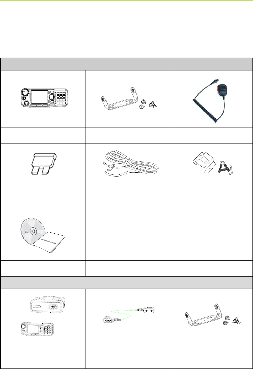
2. Items in the Package
Please unpack carefully and check that all items listed below are received. If any item is missing or
damaged, please contact your dealer.
For Mobile Terminal
Mobile Terminal Mounting Bracket Kit (1set) Palm Microphone
Fuse Power Cord
Microphone Hanger and
Screws
Documentation Kit
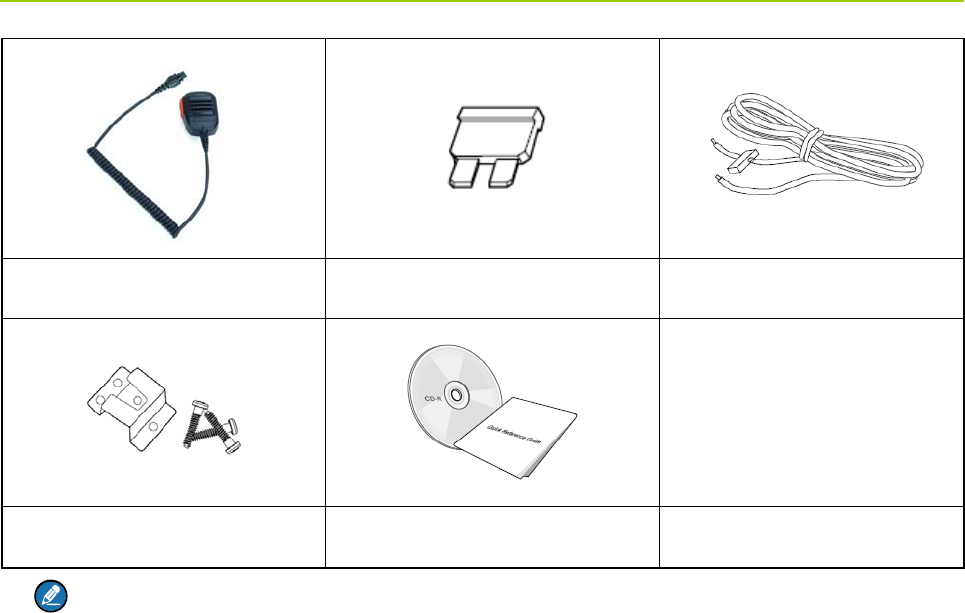
For Mobile Terminal (Remote Mounted)
Mobile Terminal (Remote
Mounted)
Remote Mounting Cable Mounting Bracket Kit (2 sets)
Items in the Package Owner’s Manual
4
Palm Microphone Fuse Power Cord
Palm Hanger and Screws Documentation Kit
Note: The antenna frequency band is marked on the label of antenna; if not, refer to the label on
the product for frequency band information.
Owner’s Manual Product Overview
5
3. Product Overview
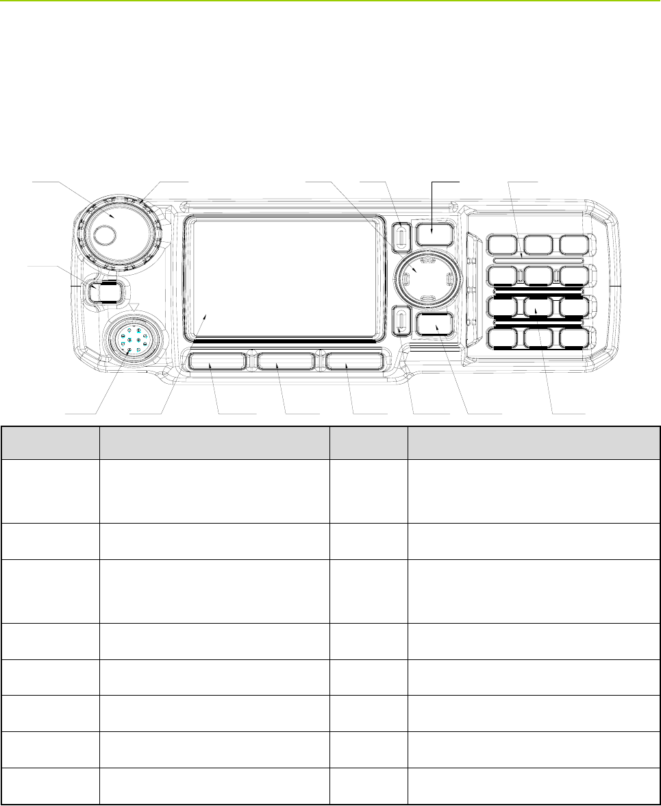
3.1 Front Panel
No. Part Name No. Part Name
1
Microphone/Programming Cable
Connector
9 Numeric Keypad
2 Emergency Key 10 Answer/Call Key
3
Volume Control/Group Selector
Knob
11 OK Key
4 LED Indicator 12 Options/P3 Key
5 Navigation Key 13 GPS/P2 Key
6 Back Key 14 Function/P1 Key
7 Power On-Off/End Key 15 LCD Display
8 Speaker / /
Product Overview Owner’s Manual
6
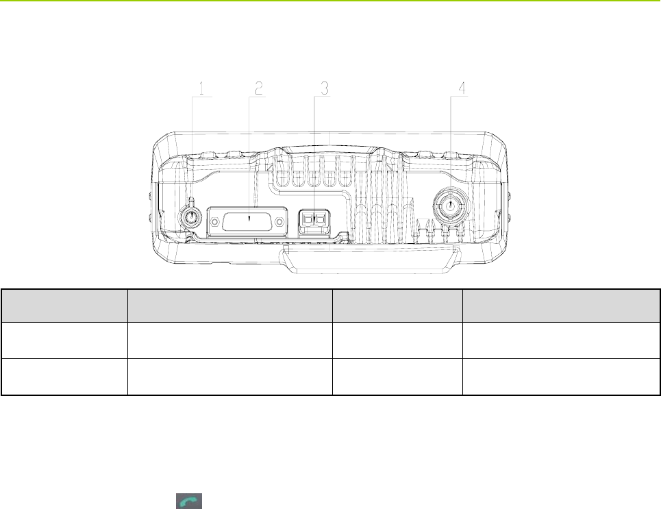
3.2 Rear Panel
No. Part Name No. Part Name
1 GPS Antenna Connector 2 Accessory Connector
3 Power Inlet 4 BNC Antenna Connector
3.3 Programmable Keys
For enhanced convenience, you can request your dealer to program the keys (navigation keys, numeric
keys 1–9, * key, # key and key) as the shortcuts to needed menus and functions. For the detailed
introduction, please read the corresponding TETRA Terminal Series Feature Book.

Owner’s Manual Before Use
7
4. Before Use
4.1 Installation
4.1.1 Installation Instructions
z This terminal is designed for a 10.8–15.6V (typical: 13.2V) negative ground electrical system. Please
check the ground polarity and voltage of the vehicle power supply before you install this terminal.
z Plan a proper position to ensure sufficient space for heat dissipation, thus avoiding unexpected
damage to other equipments in the vehicle due to overheating of the terminal that operates under
high current.
z It is suggested to route the antennas and power cords in a concealed way, so that the driver can
access the controls and operate easily.
4.1.2 Installation Tools
Item Qty.
Digital multimeter 1
Slotted screwdriver 1
Philips screwdriver 1
Torx screwdriver 1
Adjustable wrench 1
Hex socket sleeve kit 1
Electric iron (40W) 1
Electric drill (better with battery) 1
Needle nose pliers 1
Diagonal pliers 1
Cable tie several
Insulation tape several
Before Use Owner’s Manual
8
4.1.3 Installation Steps
For Mobile Terminal
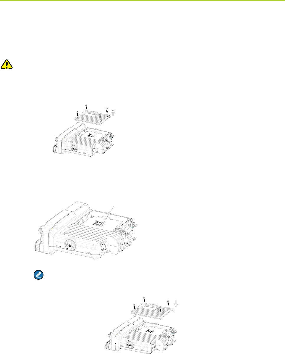
Step 1 Install the SIM card.
Caution: If a SIM card is required to realize the End-to-End Encryption (E2EE) feature which should
be purchased separately, please install the SIM card first. Otherwise, you can start from Step 2.
1. Loosen the four screws on the bottom chassis, and remove the cover.
2. Insert the SIM card properly into the holder.
Note: Ensure that the waterproof ring is attached into the groove properly.
3. Return the cover and fasten the screws back on the chassis.
Step 2 Choose the installation site.
Taking into consideration the sizes of the terminal and the mounting bracket, survey the
installation site and choose an appropriate location in vehicle, so as to ensure driving safety
and communication quality.
6,0&DUG+ROGHU
SIM Card Holder
Owner’s Manual Before Use
9
Step 3 Secure the terminal.
Drill the holes at the place for installation according to the holes on the mounting bracket
template, and secure the terminal with screws. (See “Illustration for Fixing the Mounting
Bracket ” in “Appendix”).
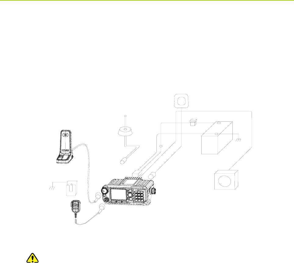
Step 4 Connect all the needed accessories to the terminal as shown below:
Palm Microphone
([WHUQDO6SHDNHU
Desktop Microphone
Power
Supply
Fuse
GPS
Antenna
Antenna
Power
Cord
Microphone Hanger
1. Connect the power cord.
Caution: Before the connection, ensure that the fuse is inserted into the fuse holder on
the power cord.
a. Connect the power cord to the power supply, with its black lead connected to the
NEGATIVE pole and its red lead to the POSITIVE pole.
b. Plug the other end of the power cord into the power inlet of the terminal.
2. Connect the antenna: align the opening of antenna connector with the stud inside the BNC
antenna jack and insert it into the jack, and then rotate the antenna connector clockwise until
a click is heard. (The antenna needs to be purchased separately.)
3. Connect the GPS antenna: align the GPS antenna connector with the GPS antenna jack on
the terminal, and rotate the connector clock-wise to fasten it. (The GPS antenna needs to be
purchased separately.)
4. Connect the palm microphone.
Before Use Owner’s Manual
10
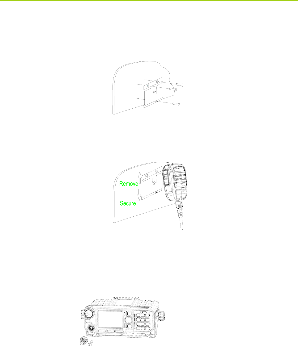
a. Install the microphone hanger: mount the hanger at a convenient position near the
terminal. Align the screw holes on the hanger with the installation holes on the chosen
position, and fasten the screws. See the figure below.
b. Place the palm microphone onto the hanger.
c. Connect the palm microphone to the terminal: align the triangle mark on the microphone
port with that above the microphone connector on the terminal. Plug the microphone port
into the connector with force. Then rotate the cover of the microphone port clockwise to
secure the microphone.
For Mobile Terminal (Remote Mounted)
Step 1 Choose the place for installation.
Take into consideration the size of the terminal and the mounting bracket, as well as the actual
requirements on the vehicle, so as to ensure driving safety and communication quality.
Step 2 Install the remote control head (i.e. the front panel) and the terminal.
Owner’s Manual Before Use
11
Drill holes at the place for installation and secure both the remote control head and the terminal
(See “Illustration for Fixing the Mounting Bracket ” in “Appendix”).
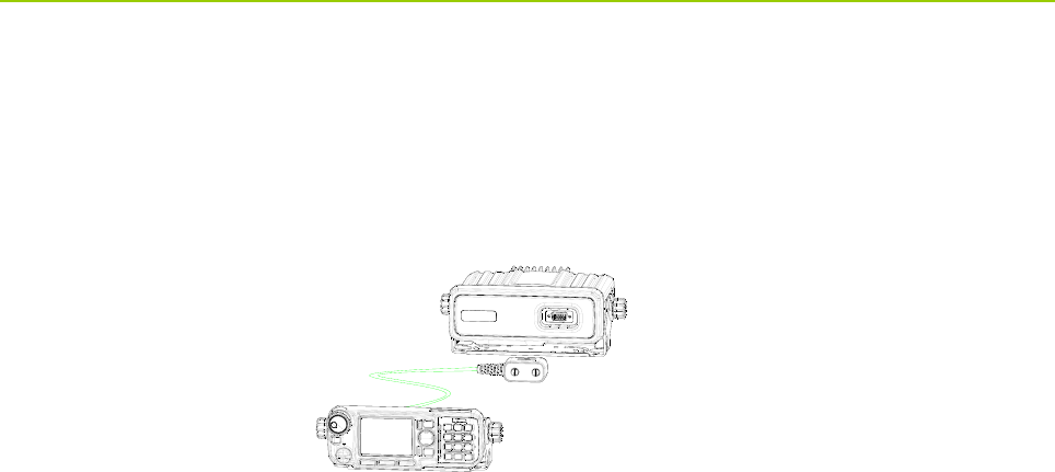
Step 3 Connect the remote control head to the terminal with the remote mounting cable.
Step 4 Connect the accessories following Step 4 for installation of mobile terminal.
After the installation, the terminal is ready for use.
Status Indication Owner’s Manual
12
5. Status Indication
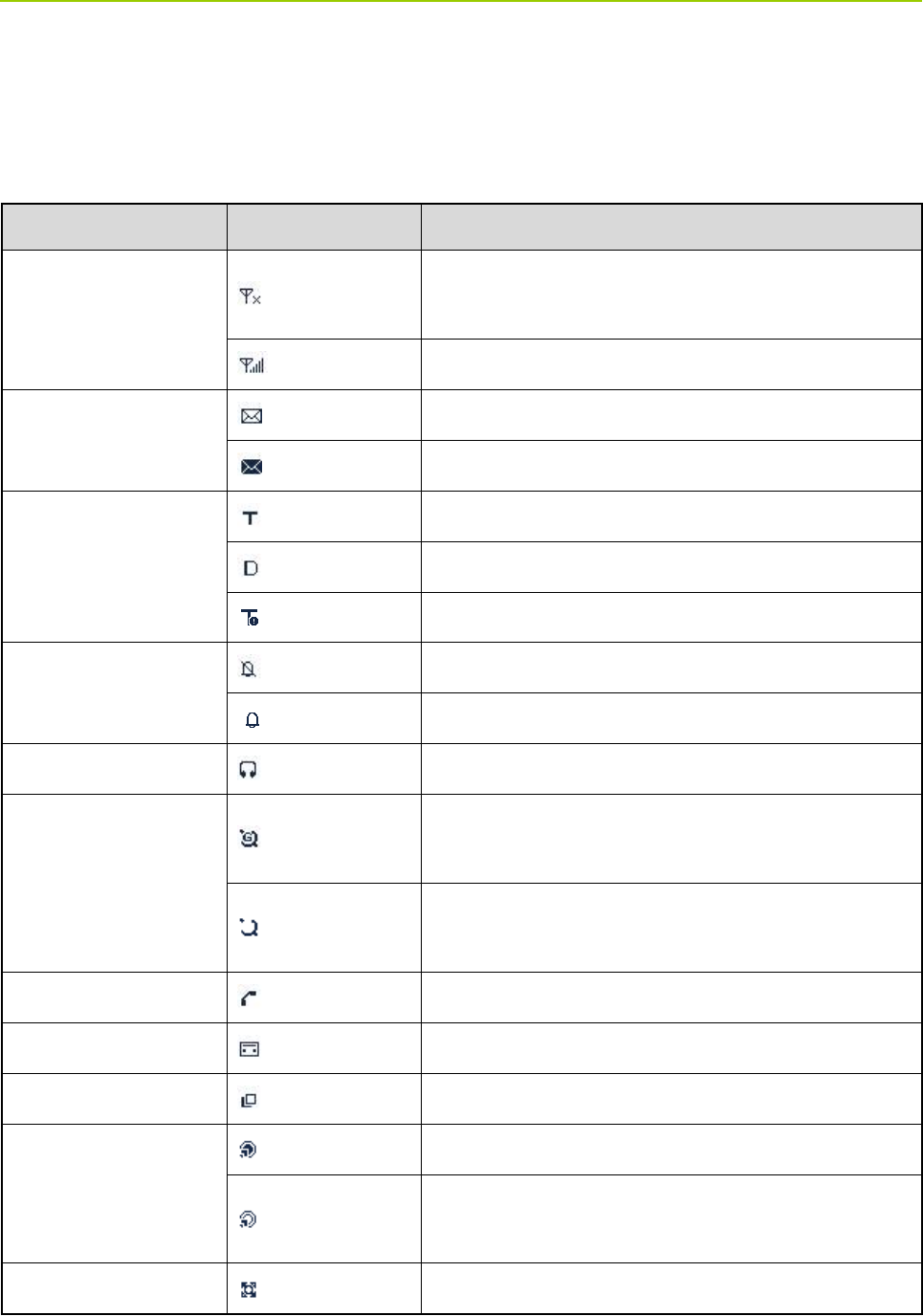
5.1 Status Icon
Name Icon Indication
RSSI Icon
The terminal has not registered with the network
(applicable for TMO only).
More bars indicate better signal strength.
Message Icon
Unread message(s).
The Inbox is full.
Operation Mode Icon
The terminal is operating in TMO.
The terminal is operating in DMO.
The terminal is operating in fall-back mode.
Profile Icons
Silent
Normal
Accessory Icon The audio accessory is connected.
GPS Icon
A GPS module is connected and the valid GPS data is
received.
A GPS module is connected but no valid GPS data is
received.
Call Icon A call is in progress.
Record Icon Recording is in progress.
Group Selection Icon The terminal is selecting a talkgroup.
Gateway Icon
A gateway device is available and connected in DMO.
A gateway device is available but not connected in
DMO.
Repeater Icon A repeater is available and connected in DMO.
Owner’s Manual Status Indication
13
Name Icon Indication
A repeater is available but not connected in DMO.
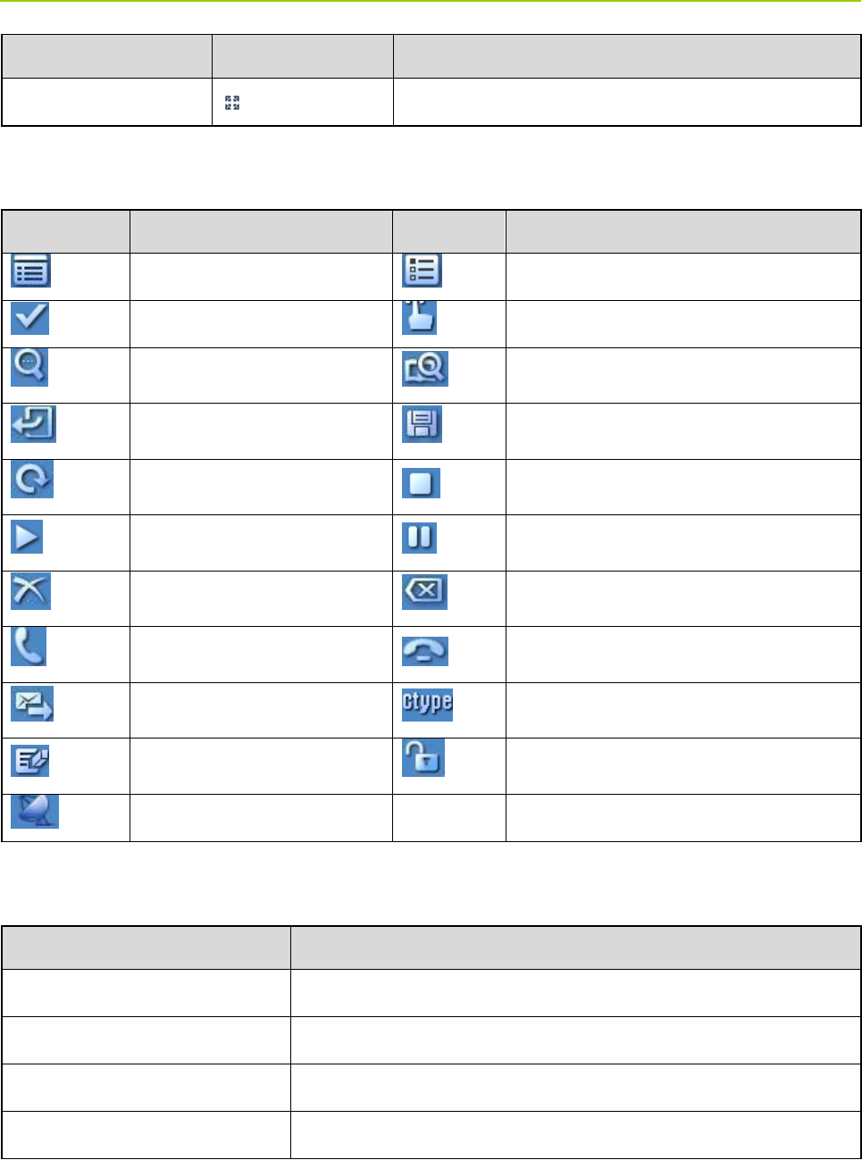
5.2 Operation Icon
Icon Indication Icon Indication
Function Menu Options Menu
OK Operate
View Search
Back Save
Restore Stop
Play Pause
Delete Cancel
Answer End
Send Call Type
Modify Unlock
GPS
5.3 LED Indicator
LED Indication Terminal Status
Glows red. Transmitting
Glows green. Receiving
Flashes green slowly Channel free in DMO
Glows orange. Channel busy in DMO .

Menu Navigation Owner’s Manual
14
6. Menu Navigation
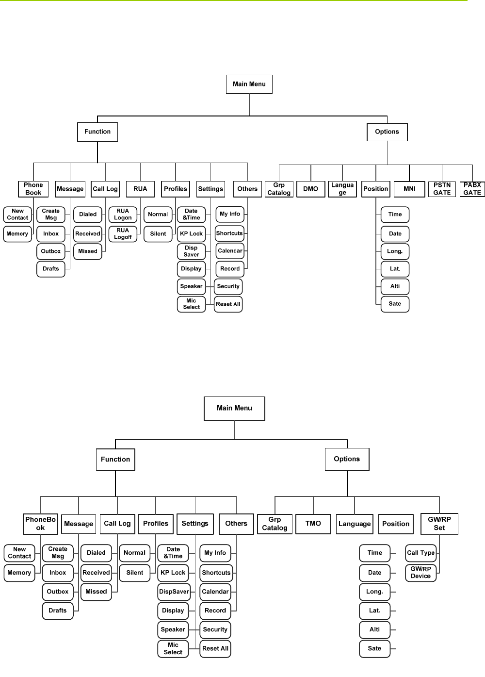
The following menu lists show the full menus of the terminal in TMO and DMO. You can select your
needed menus to be displayed via your dealer. To select and confirm the options in the menu, operate
as follows: in the home screen, you can press the OK key or Function/P1 key to enter the “Function”
menu, or press the Back key or Options/P3 key to enter the “Options” menu; then press the Up/Down
key on the Navigation key to select the needed menu, finally press the OK key.In sections introducing
operations, a menu path is provided for your convenience, e.g. Message -> Create Msg.
Owner’s Manual Menu Navigation
15
6.1 TMO Menu
6.2 DMO Menu

Basic Operations Owner’s Manual
16
7. Basic Operations
7.1 Turning On/Off
To turn on the terminal, long press the Power On-Off/End key. Then the LED indicator will glow red and
the power-up greeting appears on the LCD. In TMO, after being turned on, the terminal will logon to the
network. In DMO, the terminal will be ready for use after being turned on.
To turn off the terminal, long press the Power On-Off/End key until the power-off screen appears.
7.2 Switching Operation Mode
This terminal can operate in either TMO or DMO. To switch the operation mode, press the Options/P3
key in the home screen to enter the “Options” menu, and then select “TMO” or “DMO”.
7.3 Adjusting the Call Volume
Rotate the Volume Control/Group Selector knob clockwise to increase the call volume, or
counter-clockwise to decrease the volume. After the adjustment, the terminal will save the settings and
return to the former screen automatically.
7.4 Inputting through Keypad
You can use the numeric keypad to enter user alias and number, edit messages, etc. The terminal
supports these input methods: English and Number. To switch the input method, press the key
on the numeric keypad. In either input method, you can enter special characters and common
punctuations by pressing ,enter “*” by pressing and enter a space by long pressing this key.
As for other language input methods (depending on your customization), operate accordingly.
7.5 Locking/Unlocking the Keypad
To enable the keypad lock, enter the Function menu by pressing the Function/P1 key or the OK key in
the home screen, and then go to “Settings -> KP Lock -> On”. After this feature is enabled, keypad will
get locked automatically when the preset time (preset by the dealer) expires. To unlock the keypad,you
can press the OK key and then .
Apart from locking the keypad via menu, you can lock the keypad quickly and temporarily by pressing
the OK key and then directly in the home screen.

Owner’s Manual Basic Operations
17
7.6 PIN Code Security and Changing
PIN code can prevent unidentified users from using your terminal. To enable or disable the PIN Code
feature, enter the Function menu from the home screen by pressing the Function/P1 key or OK key,
and then go to “Settings -> Security -> PIN Code”. Every time you need to change the settings, it is
required to input the PIN code first (default PIN code: 1234, preset by the dealer).
With this feature enabled, you will need to enter the correct PIN code prior to operating the terminal after
turning it on. If you input the wrong code for continuous 3 times (predefined by the dealer), the terminal
will be locked. In this case, you will need to enter the correct PUK code (default PUK code: 12345678) to
reset the PIN code. To change the PIN code, go to “Settings -> Security -> ChangePIN” from the home
screen, and input the correct current PIN code prior to changing the code.
7.7 Managing the Contacts
7.7.1 Contact List
The contact list saves the information of individual call contacts. To view the list, press the Function/P1
key or OK key to enter the Function menu and then go to the “PhoneBook” menu.
7.7.2 New Contact
To add a new contact, you can enter the Function menu by pressing the Function/P1 key or OK key and
go to “PhoneBook”. Then press the OK key to enter “Options -> New Contact” to add a new contact:
enter the contact’s alias in the editing screen, and press the OK key to enter the “Input No.” screen to
input the contact number. And, press the OK key again to select the call type (“Private No.”, “PABX” or
“PSTN”). Finally, press OK key to confirm.
7.7.3 Viewing the Memory
To view the phonebook memory , you can enter the Function menu by pressing the Function/P1 key or
OK key, and go to “PhoneBook” menu; then press OK with the screen-icon to enter “Options ->
Memory”.

Call Services Owner’s Manual
18
8. Call Services
8.1 TMO
8.1.1 Individual Call
In TMO , an individual call can be initiated either as a half-duplex call or full-duplex call, which can be
received without pressing any key (Direct Signaling) or by pressing the Call key or PTT (Hook Signaling).
Contact your dealer for such programming as well as more details.
Initiating an Individual Call
z Via Menu
In the home screen, press Function/P1 key or OK key to enter the “PhoneBook” or “Call Log”
submenu, and select a contact. Then press PTT to initiate a half-duplex call, or press to initiate
a full-duplex call.
z Via Manual Dial
In the home screen, input the number you want to call through the keypad, and select “Private No.”
through the OK key with the screen-icon . Then press PTT to initiate a half-duplex call, or press
to initiate a full-duplex call.
Note:
¾Entry of individual numbers must comply with the SSI&TSI dialing rules. See “SSI&TSI Dialing
Rules” in “Appendix” for more details.
¾Calls will end automatically if the predefined call timer expires.
Answering an Individual Call
z Half-duplex Individual Call
¾If it is an incoming call with Direct Signaling, there will be an alert tone to inform the called party
that a call is received..
¾If it is an incoming call with Hook Signaling, the terminal sounds alert to inform the called party
that there is an incoming call. And to receive the call, the PTT key should be pressed .
To take the talk rights during the call, there are two situations: 1) if you have no pre-emptive priority,
hold down PTT to talk after the talking party stops talking and releases its PTT; 2) if you have already
been programmed with pre-emptive priority, hold down PTT to talk at any time.
z Full-duplex Individual Call

Owner’s Manual Call Services
19
¾If it is an incoming call with Direct Signaling, there will be an alert tone to inform the called party
that a call is received..
¾If it is an incoming call with Hook Signaling, the terminal sounds alert tone to inform the called
party that there is an incoming call. And to receive the call, the PTT key or should be pressed.
After the call is established, both parties can talk at any time, with no need to use any key.
Note:
There may be an exception, that is, if your terminal has been programmed to transmit
using PTT in a full-duplex call, you have to hold down PTT to talk. In this case, you may
miss voices from the other party when both parties are talking.
Hanging up/ Rejecting an Individual Call
When initiating the individual call, press the Back key or to terminate it.
In the presence of an incoming individual call, press the Back key or to reject it.
In the process of an individual call, any party can press to terminate it.
8.1.2 Group Call
Initiating a Group Call
In the home screen, you can initiate a group call to the default group by pressing PTT. To call other
groups, please do as follows:
Step 1 In the home screen, press the Volume Control/Group Selector knob and the icon
appears on the upper right corner of the screen.
Step 2 Rotate the knob to select a group.
Please perform this step as soon as the icon appears; otherwise, you may fail to select.
Step 3 Press the knob or OK key to confirm your selection.
Step 4 Press PTT to initiate a group call to this group.
Answering a Group Call
You can receive a group call without any operation. To take the talk rights during the call, there are two
situations: 1) if you have no pre-emptive priority, hold down PTT to talk after the talking party stops
talking and releases its PTT; 2) if you have already been programmed with pre-emptive priority, hold
down PTT to talk at any time.
Hanging up a Group Call
The calling party can press to exit a group call. And for the called parties in a group call, only those
enabled with “Hang Up” feature (programmable by the dealer) can exit a group call.

Call Services Owner’s Manual
20
8.1.3 Telephone Call
The telephone call is a full-duplex individual call with Hook signaling. To initiate the call, follow the steps
below.
Initiating a Telephone Call
Step 1 Select a gateway.
In the home screen, press the Back key or Options/P3 key to enter the “PSTN GATE” or
“PABX GATE” submenu. Select an appropriate gateway, and press Function/P1 key or OK key
to confirm.
Step 2 Input a telephone number.
Return to the home screen by pressing . Input a PABX or PSTN number, which is
composed of a prefix (specified by the gateway, please contact the system administrator) and
the telephone number of the target contact.
Step 3 Select a call type.
Select “PABX” or “PSTN” through the OK key with the screen-icon .
Step 4 Press to initiate the call.
To answer or hang up/reject the call; see the “Individual Call” in “TMO”.
8.1.4 Emergency Call
Initiating an Emergency Call
Press the Emergency key and you can initiate an emergency call to the predefined contact. Any
individual contact, group contact, default group, PSTN or PABX contact can be predefined as the
emergency contact.
There are two levels for emergency call: emergency priority and pre-emptive priority 3, which can be
programmed by your dealer. The emergency priority is endowed with the higher privilege; thus a call with
such priority can break any other call with pre-emptive priority 3, as well as calls with lower priorities.
Answering an Emergency Call
The emergency call is always received automatically. During an emergency call, the initiating party can
talk with no need to use any key. If another member needs to talk, he/she should hold down PTT only
after the talking party stops talking and releases its PTT.
Hanging up an Emergency Call
See the corresponding part of “Individual call” or “Group call” in accordance with the call type of the

Owner’s Manual Call Services
21
predefined contact.
8.2 DMO
8.2.1 Individual Call
In DMO, an individual call can be initiated only as a half-duplex call.
Initiating an Individual Call
In the home screen, directly input the number you want to call through the keypad, or press Function/P1
key or OK key to enter the “PhoneBook” or “Call Log” submenu, and select a contact. Then press PTT to
initiate the call.
Note:
Entry of individual numbers must comply with the SSI&TSI dialing rules. See “SSI&TSI Dialing Rules”
in “Appendix” for more details.
Answering an Individual Call
You can receive an individual call in DMO automatically. During the call, you can hold down PTT to talk
after the initiating party stops talking and releases its PTT.
Hanging up an Individual Call
The calling party can press to terminate an individualthe call. And the called party can press
to exit the call.
8.2.2 Group Call
Group calls in DMO is the same as that in TMO. Please refer to operation method described in ”Group
Call” in the above “TMO” section.
8.2.3 Emergency Call
In DMO, emergency calls are endowed with emergency priority only. Please refer to operation method
described in ”Emergency Call” in the above “TMO” section.

Message Owner’s Manual
22
9. Message
9.1 Status Message
Status message, which should be programmed by your dealer only, can facilitate instant messaging of
the frequently-used messages. You can only send or view rather than editing the status messages.
When the message is sent successfully, the target terminal will receive either the status ID of the status
message (if the message text has not been predefined via CPS) or the predefined text (if the message
text has been predefined via CPS).
Sending a Status Message
z Press the Function/P1 key or OK key and navigate to “Message -> Create Msg -> StatusMsg -> Sel
Msg”. Select a desired status message, and press the OK key to proceed. Choose either an
individual or a group as the target contact, input the appropriate number and press OK to complete.
Long press the programmed Send StatusMsg key to send the preset status message directly.
View the Status Message
When the icon appears in the status bar, it indicates there is/are unread message(s). Do as follows
to view it:
z In the prompt screen for an unread message, press the OK key to enter the Inbox, and press OK key
again to read.
z In the home screen, press the Function/P1 key or OK key and navigate to “Message -> Inbox ”.
Then you can view the unread message.
9.2 User Message
9.2.1 TMO
Editing a User Message
Press the Function/P1 key or OK key and navigate to “Message -> Create Msg -> User Msg”. Press OK
again to edit a user message.
Sending a User Message
After editing, press OK to confirm. Then select the target contact and decide whether to send it as a flash
message.

Owner’s Manual Message
23
Note:
If the message is sent as a flash message, the receiving party can preview all the content in a
predefined time period without any operation. Once the time period expires, the home screen will get
restored, with the icon displaying on the status bar.
Viewing the User Message
When the icon appears in the status bar, it indicates there is/are unread message(s). Do as follows
to view it:
z In the prompt screen for unread message(s), press the OK key to enter the Inbox, and press OK
again to read.
z In the home screen, press the Function/P1 key or OK key and navigate to “Message -> Inbox ->
Inbox”. Then you can view the unread message.
9.2.2 DMO
Editing a User Message
Press the Function/P1 key or OK key and navigate to “Message -> Create Msg -> User Msg”. Press OK
key again to edit a user message.
Sending a User Message
After editing, press OK to confirm. Then choose either an individual or a group as the target contact,
input the appropriate number and press OK to complete.
Viewing the User Message
Operate in the same way as that described in ”Viewing the User Message ” in the above “TMO” section.

Troubleshooting Owner’s Manual
24
10. Troubleshooting
Phenomenon Analysis Solution
Terminals cannot be
powered on.
The power cord is connected
improperly.
Connect the power cord correctly.
An abnormal voltage is output from
the vehicle battery.
Check the battery strength.
The power cord is damaged.
Replace the power cord with a new
one.
The terminal and the remote control
head are connected improperly (for
mobile terminal (remote
mounted)only).
Replace the remote mounting cable
with a new one and connect the
terminal to the remote control head
correctly.
Network registration
fails or network can
not be found.
The terminal is operating in DMO . Switch to TMO mode.
The terminal is out of the network
coverage in TMO.
Check the signal strength. Make
sure the terminal is within the
network coverage.
The terminal is not granted network
access.
Contact the network operator for the
terminal authorization.
Calls cannot be
initiated.
The terminal is out of the network
coverage.
Check the signal strength. Make
sure the terminal is within the
network coverage.
The terminal operates in an improper
mode.
Check the operation mode. Make
sure the terminal works in the right
mode.
A group call can not
be sent or received.
The terminal is not a member of the
target group.
Check whether the terminal is a
member of the group. If not, contact
your dealer to add the terminal to the
group.

Owner’s Manual Troubleshooting
25
Phenomenon Analysis Solution
The terminal is not authorized to
access the target group.
Contact the network operator for the
terminal authorization.
Calls are always
interrupted.
The current channel is assigned to
emergency calls or other calls with
higher priority.
Wait until the channel becomes
available and try again.
A half-duplex can not
be established.
The predefined time period for
establishing a call expires.
Make sure the call is established
within the predefined time period.
The channel is occupied by another
terminal with higher call priority.
Wait until the channel becomes
available and try again.
The channel resources are allocated
to other services due to overloaded
network.
Wait until the channel becomes
available and try again.
Abnormal
disconnection occurs
during a call.
The terminal gets out of the network
coverage (in TMO).
Check the signal strength. Make
sure the terminal is within the
network coverage.
The terminal operates at an
unfavorable position where
communication may be blocked by
high buildings or frustrated in the
underground areas (in DMO).
Move to an open and flat area, and
restart the terminal.
As for the same
status message ID,
the content displayed
at the receiving party
is different from that
of the sending party.
The parties have associated the
same status message ID with
different contents.
Make sure the status message ID is
associated with the same content.
The called party
cannot hear clearly.
The calling party’s palm microphone
and the terminal are connected
improperly.
Connect the microphone to the
terminal correctly.

Troubleshooting Owner’s Manual
26
Phenomenon Analysis Solution
The palm microphone is damaged.
Replace the microphone and
connect the new one to the terminal
correctly.
If the above solutions can not fix your problems, or you may have some other queries, please contact us
or your local dealer for more technical support.

Owner’s Manual Care and Cleaning
27
11. Care and Cleaning
To guarantee optimal performance as well as a long service life of the product, please follow the tips
below.
Product Care
z Do not pierce or scrape the product.
z Keep the product far away from substances that can corrode the circuit.
z Do not hold the product by its antenna or earpiece cable directly.
z Attach the accessory jack cover when the product is not in use.
Product Cleaning
Caution: Power off the product and disconnect the power supply before cleaning.
z Clean up the dust and fine particles on the product surface and charging piece with a clean and dry
lint-free cloth or a brush regularly.
z Use neutral cleanser and a non-woven fabric to clean the keys, control knobs and front case after
long-time use. Do not use chemical preparations such as stain removers, alcohol, sprays or oil
preparations, so as to avoid surface case damage.
z Make sure the product is completely dry before use.

Appendix Owner’s Manual
28
12. Appendix
12.1 SSI&TSI Dialing Rules
In the TETRA system, subscribers are distinguished by different identities. Each subscriber is assigned
with a unique short subscriber identity (SSI), which serves a part of the TETRA subscriber identity (TSI).
And TSI is generally composed in this way: Mobile Country Code (MCC) + Mobile Network Code (MNC)
+ SSI. To initiate an individual call, please dial the SSI or TSI in compliance with the rules below.
z SSI Dialing
Make sure there are not more than 8 digits.
z TSI Dialing
¾MNC+SSI:
1) Input the MNC as it is;
2) SSI must be 8 digits long. Add 0 before the first digit of SSI which is shorter than 8 digits.
For example, when MNC is 20 and SSI is 504, you need to input 2000000504.
¾MCC+MNC+SSI:
1) MCC must contain 3 digits. Add 0 before the first digit of MCC which is shorter than 3 digits;
2) MNC must contain 4 or 5 digits. When the MNC is shorter than 4 digits, add 0 before its first
digit; when it is 5 digits long, use it directly;
3) SSI must be 8 digits long. Add 0 before the first digit of SSI which is shorter than 8 digits.
For example, when MCC is 460, MNC is 20 and SSI is 504, you need to input 460002000000504.
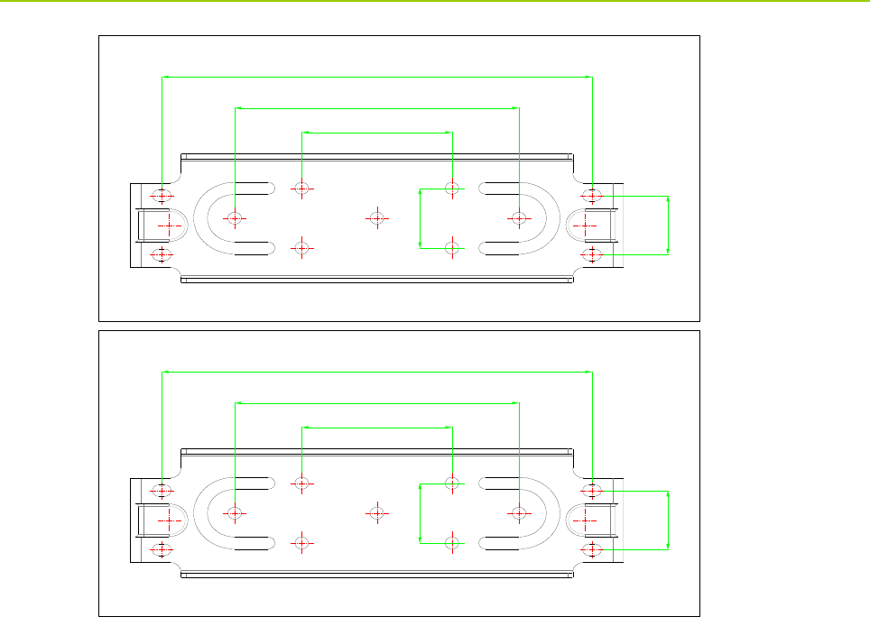
12.2 Illustration for Fixing the Mounting Bracket
Owner’s Manual Appendix
29
8QLW˖PP
8QLW˖PP