Hytera Communications PD36XUC Digital Portable Radio User Manual
Hytera Communications Corporation Ltd. Digital Portable Radio
User Manual

Preface
Thanks for your favor in our product. This manual is helpful for you to quickly know how to use the
product.
This manual is applicable to the following product:
PD36XUc Digital Portable Radio
(X may represent 0,2, 5, 6 or 8)

Instructional Icons
: Indicates functions that are available on digital channel only.
: Indicates functions that are available on analog channel only.
Functions marked with no function icons are available on both analog and digital channels.
Disclaimer
Hytera Communications Co., Ltd. (“the Company”) endeavors to achieve the accuracy and
completeness of this manual, but no warranty of accuracy or reliability is given. All the specifications and
designs are subject to change without notice due to continuous technology development. No part of this
manual may be copied, modified, translated, or distributed in any manner without the express written
permission of us.
We do not guarantee, for any particular purpose, the accuracy, validity, timeliness, legitimacy or
completeness of the Third Party products and contents involved in this manual.
If you have any suggestions or would like to learn more details, please visit our website at:
http://www.hytera.com.
RF Radiation Information
This product must be restricted to operations in an Occupational/Controlled RF exposure Environments.
Users must be fully aware of the hazards of the exposure and able to exercise control over their RF
exposure to qualify for the higher exposure limits.
RF Radiation Profile
Radio Frequency (RF) is a frequency of electromagnetic radiation in the range at which radio signals are
transmitted. RF technology is widely used in communication, medicine, food processing and other fields.
It may generate radiation during use.
RF Radiation Safety
In order to ensure user health, experts from relevant industries including science, engineering, medicine
and health work with international organizations to develop standards for safe exposure to RF radiation.
These standards consist of:
United States Federal Communications Commission, Code of Federal Regulations; 47CFR part 2
sub-part J;

American National Standards Institute (ANSI)/Institute of Electrical and Electronic Engineers (IEEE)
C95. 1-1992;
Institute of Electrical and Electronic Engineers (IEEE) C95.1-1999;
International Commission on Non-Ionizing Radiation Protection (ICNIRP) 1998.
FCC Regulations
Federal Communication Commission (FCC) requires that all radio communication products should meet
the requirements set forth in the above standards before they can be marketed in the U.S, and the
manufacturer shall post a RF label on the product to inform users of operational instructions, so as to
enhance their occupational health against exposure to RF energy.
Operational Instructions and Training Guidelines
To ensure optimal performance and compliance with the occupational/controlled environment RF energy
exposure limits in the above standards and guidelines, users should transmit not more than 50% of the
time and always adhere to the following procedures:
RF energy will be generated only when the radio is transmitting.
The radio must be 2.5 centimeters away from human body when transmitting.
FCC Statement
This equipment has been tested and found to comply with the limits for a Class B digital
device, pursuant to part 15 of FCC Rules. These limits are designed to provide
reasonable protection against harmful interference in a residential installation. This
equipment generates and can radiate radio frequency energy and, if not installed and
used in accordance with the instructions, may cause harmful interference to radio
communications. However, there is no guarantee that interference will not occur in a
particular installation. If this equipment does cause harmful interference to radio or
television reception, which can be determined by turning the equipment off and on, the
user is encouraged to try to correct.
The interference by one or more of the following measures:
● Reorient or relocate the receiving antenna. Increase the separation between the
equipment and receiver.
● Connect the equipment into an outlet on a circuit different from that to which the

receiver is connected.
● Consult the dealer or an experienced radio/TV technician for help
Operation is subject to the following two conditions: 1. This device may not cause harmful
interference, and 2. This device must accept any interference received, including
interference that may cause undesired operation.
Note:” Changes or modifications to this unit not expressly approved by the party
responsible for compliance could void the user’s authority to operate the equipment.”
Compliance with RF Exposure Standards
Hytera’s 2-way radio complies with the following RF energy exposure standards and
guidelines:
• United States Federal Communications Commission, Code of Federal Regulations; 47
CFR §§ 1.1307, 1.1310 and 2.1093
• American National Standards Institute (ANSI) / Institute of Electrical and Electronic
Engineers (IEEE) C95. 1-1992
• Institute of Electrical and Electronic Engineers (IEEE) C95.1-1999 Edition
RF Exposure Compliance and Control Guidelines and
Operating Instructions
To control your exposure and ensure compliance with the occupational/controlled
environment exposure limits always adhere to the following procedures.
Guidelines:
• Do not remove the RF Exposure Label from the device.
• User awareness instructions should accompany device when transferred to other users.
• Do not use this device if the operational requirements described herein are not met.
Operating Instructions:
• Transmit no more than the rated duty factor of 50% of the time. To transmit (talk), push

the Push-To-Talk (PTT) button. To receive calls, release the PTT button. Transmitting
50 % of the time, or less, is important because this radio generates measurable RF
energy exposure only when transmitting (in terms of measuring for standards
compliance).
• Hold the radio in a vertical position in front of face with the microphone (and the other
parts of the radio, including the antenna) at least one inch (2.5 cm) away from the nose.
Keeping the radio at the proper distance is important because RF exposures decrease
with distance from the antenna. Antenna should be kept away from eyes.
• When worn on the body, always place the radio in a Hytera’s approved clip, holder,
holster, case, or body harness for this product. Using approved body-worn accessories is
important because the use of Hytera’s or other manufacturer’s non-approved accessories
may result in exposure levels, which exceed the FCC’s occupational/controlled
environment RF exposure limits.
• If you are not using a body-worn accessory and are not using the radio in the intended
use position in front of the face, then ensure the antenna and the radio are kept at least
2.5 cm (one inch) from the body when transmitting. Keeping the radio at the proper
distance is important because RF exposures decrease with increasing distance from the
antenna.
• Use only manufacturer’s name approved supplied or replacement antennas, batteries,
and accessories. Use of non-manufacturer-name approved antennas, batteries, and
accessories may exceed the FCC RF exposure guidelines.
•For a list of Hytera’s approved accessories (see the user manual), or (visit the following
website which lists approved accessories: http: add website address), or(The
manufacturer should include the appropriate bracketed item{s} in the manual.)
• For a list of Hytera’s approved accessories (see the user manual), or (visit the following
website which lists approved accessories: www.hytera.cn
IC statement

The device has been tested and compliance with SAR limits, users can obtain Canadian
information on RF exposure and compliance
Après examen de ce matériel aux conformité aux limites DAS et/ou aux limites d’intensité
de champ RF, les utilisateurs peuvent sur l’exposition aux radiofréquences et la
conformité and compliance d’acquérir les informations correspondantes
EU Regulatory Conformance
As certified by the qualified laboratory, the product is in compliance with the essential
requirements and other relevant provisions of the Directive 1999/5/EC. Please note
that the above information is applicable to EU countries only.

Contents
1. Items in the Package .......................................................................................................................... 1
2. Product Overview ............................................................................................................................... 2
2.1 Product Controls ............................................................................................................................. 2
2.2 Programmable Keys ....................................................................................................................... 3
3. Before Use .......................................................................................................................................... 4
3.1 Charging the Battery ....................................................................................................................... 4
3.2 Attaching the Battery ....................................................................................................................... 5
3.3 Attaching the Belt Clip ..................................................................................................................... 6
3.4 Attaching the Earpiece .................................................................................................................... 6
4. Status Indication ................................................................................................................................ 8
4.1 LCD Icon ......................................................................................................................................... 8
4.2 LED Indicator .................................................................................................................................. 9
5. Menu Navigation ............................................................................................................................... 10
6. Basic Operation ................................................................................................................................ 11
6.1 Powering On/Off ........................................................................................................................... 11
6.2 Adjusting the Volume .................................................................................................................... 11
6.3 Selecting a Zone ........................................................................................................................... 11
6.4 Selecting a Channel ...................................................................................................................... 11
6.5 Locking and Unlocking the Keypad ............................................................................................... 11
7. Call Services ..................................................................................................................................... 12
7.1 Calling on Digital Channel ....................................................................................................... 12
7.2 Calling on Analog Channel (No Signaling) .............................................................................. 13
8. Features and Operations ................................................................................................................. 14
8.1 Home Screen ................................................................................................................................ 14
8.2 Contact .................................................................................................................................. 14
8.3 Message ................................................................................................................................ 14
8.4 Call Log ................................................................................................................................. 15
8.5 Scan .............................................................................................................................................. 15
8.6 Radio Settings .............................................................................................................................. 16
8.7 Device Information ........................................................................................................................ 17
8.8 One Touch Call ..................................................................................................................... 17
8.9 Time-Out-Timer............................................................................................................................. 18
8.10 Transmission Management ......................................................................................................... 18
8.11 Monitor ................................................................................................................................. 18
8.12 Squelch Off Momentary ........................................................................................................ 19
9. Troubleshooting ............................................................................................................................... 20
10. Care and Cleaning .......................................................................................................................... 22
11. Optional Accessories ..................................................................................................................... 23
1
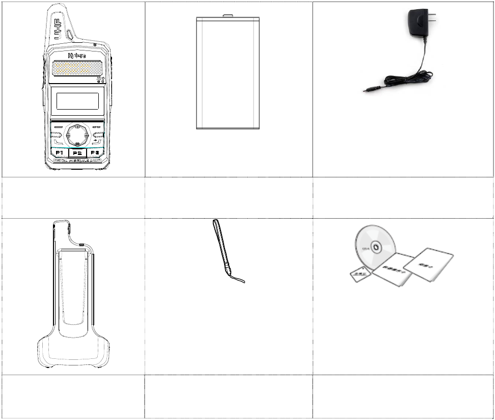
1. Items in the Package
Please unpack carefully and check that all items listed below are received. If any item is missing or
damaged, please contact your dealer.
Radio Unit Battery Power Adapter
Belt Clip Strap Documentation Kit
2
2. Product Overview
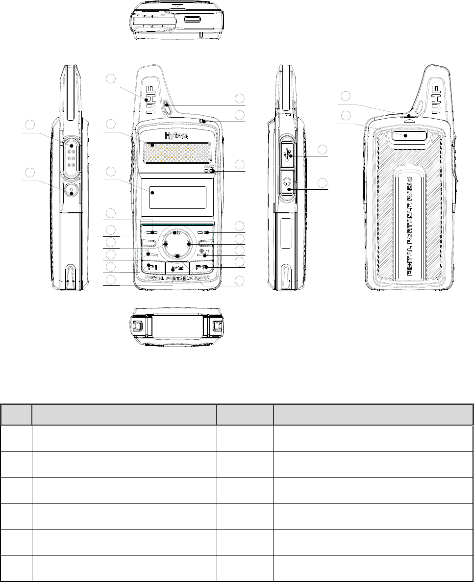
2.1 Product Controls
1
2
4
5
6
7
8
9
10
11
15
16
17
18
19
14
13
12
20
21
22
23
3
No. Part Name No. Part Name
○
1 PTT (Push-to-Talk) Key ○
13 LED Indicator
○
2 SK1 (Side Key 1) ○
14 Microphone
○
3 Antenna ○
15 Cancel/Return Key
○
4 Speaker ○
16 Volume +/Right Key
○
5 LCD Display ○
17 Power On/Off/ESC Key
○
6 OK/Menu ○
18 P3

3
No. Part Name No. Part Name
○
7 Up Key ○
19 Down Key
○
8 Volume -/Left Key ○
20 Charging/Data Connector
○
9 Call Key ○
21 Earpiece Connector
○
10 P1 ○
22 Battery Cover Open-up
○
11 P2 ○
23 Battery Cover
○
12 Strap Hole
2.2 Programmable Keys
For enhanced convenience, you may request your dealer to program the SK1, P1, P2 and P3 as
shortcuts to certain feature.
4
3. Before Use
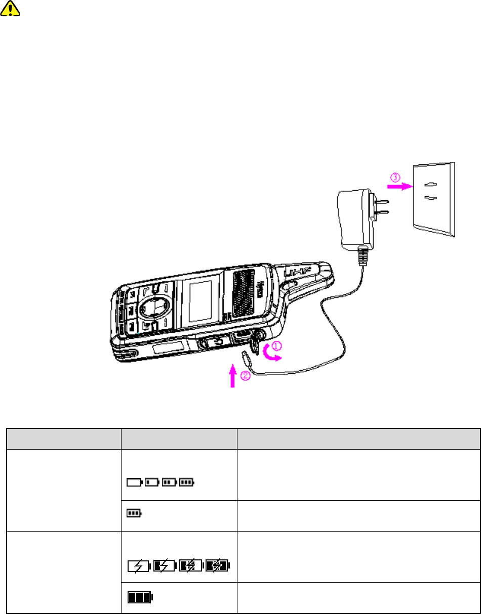
3.1 Charging the Battery
Caution:
Make sure the radio is powered off before charging. Read the Safety Information Booklet in
advance to get necessary safety information.
To achieve optimal battery performance, please charge the battery for at least 5 hours before
initial use.
Please use the power adapter specified by the Company to charge the radio (with battery attached).
Charging Diagram is listed below.
Charging Indication:
Radio Status Icon Charging Status
Power On Display in a cycle:
Charging
Fully charged
Power Off Display in a cycle: Charging
Fully charged
5
Note:
Upon being charged after the radio is powered off due to low battery voltage, the radio displays a
black screen.
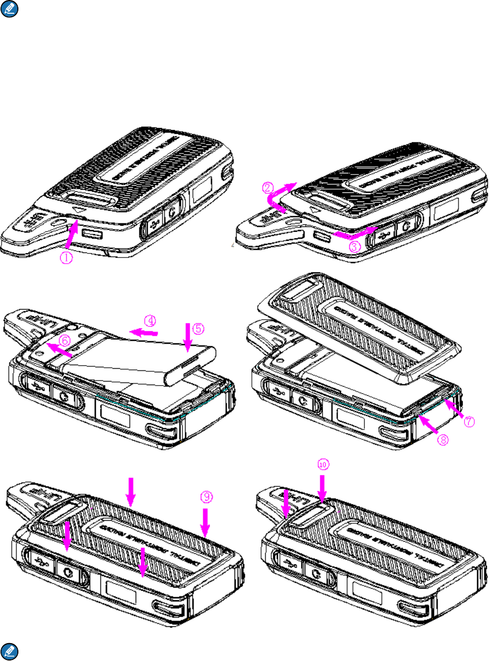
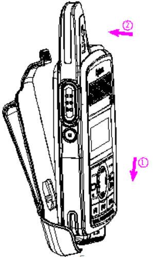
3.2 Attaching the Battery
To attach the battery, perform the following steps.
Note:
Turn off the radio before removing the battery.
6
3.3 Attaching the Belt Clip
To attach the belt clip, perform the following steps.
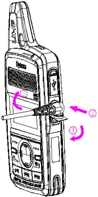
3.4 Attaching the Earpiece
Step 1 Open the connector cover as ① shown.
Step 2 Align the index of the earpiece with that of the radio and connect the earpiece to the radio as ②
shown.
Step 3 Turn the earpiece clockwise as ③ shown to fasten it.
7
8
4. Status Indication
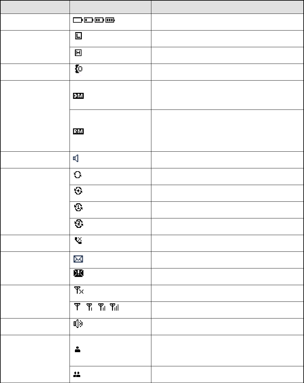
4.1 LCD Icon
Icon Name Icon Radio Status
Battery Power Icon More bars indicate more battery power.
TX Power Icon
Low power for the current channel.
High power for the current channel.
Accessory Icon An accessory is connected.
Operation Mode Icon
Direct Mode Operation: Under this mode, radios
can communicate with each other directly.
Repeater Mode Operation: Under this mode,
radios communicate with each other via a
repeater.
Monitor Icon The Monitor feature is enabled.
Scan Icon
The radio is scanning.
The radio stays on a non-priority channel.
The radio stays on Priority Channel 1.
The radio stays on Priority Channel 2.
Missed Call Icon A call is missed.
Message Icon
Unread message(s).
Inbox is full.
RSSI Icon
No signal.
More bars indicate better signal strength.
Speaker Icon The speaker is unmuted.
Call/Contact Icon
Indicates Private Call during a call.
Indicates Private Contact in the contact list.
Indicates Group Call during a call.

9
Icon Name Icon Radio Status
Indicates Group Contact in the contact list.
Indicates All Call during a call.
Indicates All Call Contact in the contact list.
4.2 LED Indicator
LED Indication Radio Status
The LED
indicator flashes
green.
Powering on.
The LED
indicator glows
green.
Receiving.
The LED
indicator glows
red.
Transmitting.
The LED
indicator flashes
orange slowly.
Scanning.
The LED
indicator flashes
orange rapidly.
Emergency.
The LED
indicator glows
orange.
During a call, you can hold down the PTT key to talk to the other party before the
call hang time expires.
10
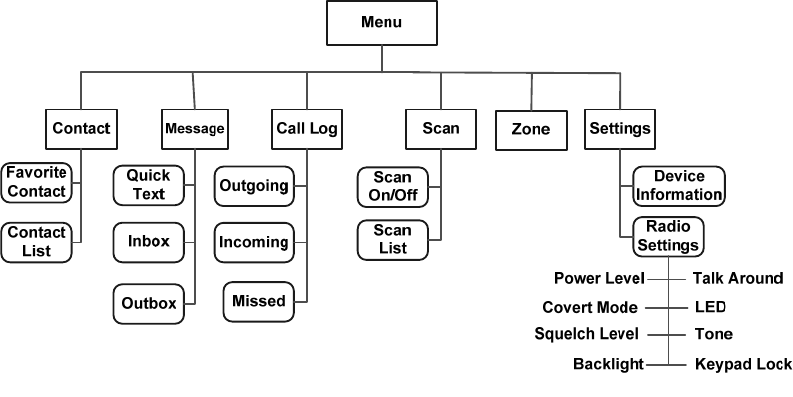
5. Menu Navigation
The following menu list shows all the menus of the radio. You can customize the menu item in the radio
via your dealer.
To select and confirm the options shown in the menu, press the OK/Menu key and then press the Up or
Down key to select your needed option, finally press the OK/Menu key. This manual only describes the
path to the menus, for example, to access the contact list, go to “Contact -> Contact List”.
The radio supports menu reset function.When you do not operate the menu for a preset time period
configured by the dealer, the radio will automatically return to the home screen. You may request the
dealer to change the auto reset time or disable the feature.
11
6. Basic Operation
6.1 Powering On/Off
Long press the Power On/Off/ESC key to power on and off the radio.
6.2 Adjusting the Volume
After the radio is powered on, you can press the Volume +/Right key to increase the volume and press
the Volume -/Left key to decrease it.
6.3 Selecting a Zone
You can include a group of channels with the same property into a zone for convenient management.
The radio supports 16 zones, each of which consists of up to 16 channels. You can select a zone
through any of the following ways:
Via the menu: Go to “Menu -> Zone”, press the Up or Down key to select an appropriate zone, and
then press the OK/Menu key to confirm it.
Via Programmable Keys: You can toggle to the appropriate zone by pressing the programmed Zone
Up or Zone Down key preset by your dealer.
6.4 Selecting a Channel
After the radio is powered on, you can press the Up or Down key to select the channel.
6.5 Locking and Unlocking the Keypad
When the keypad is not in use, you can lock the keypad to avoid mishandling. You can lock/unlock the
keypad through any of the following methods:
Key Combination: press the OK/Menu key and P1 to lock the keypad; press any key (other than PTT,
SK1, Volume -/Left key, Volume +/Right key and Power On/Off/ESC key) and P1 to unlock it.
Programmable Keys: Press the programmed Keypad Lock key preset by your dealer.
Via the menu: Go to “Settings -> Radio Settings -> Keypad Lock” to enable or disable the feature.
Enable: The keypad will be locked if there is no radio operation within the preset time.
Disable: The keypad will not be locked automatically. But you can lock/unlock the keypad via
methods mentioned above.

12
7. Call Services
After the radio is powered on, you can make and receive calls. To ensure optimal volume of the
receiving radio, keep the microphone about 2.5 to 5 centimeters away from your mouth when
transmitting.
Private call: It is a voice call between individual user and another individual user.
Group call: It is a voice call between one individual user and a predefined group of users. All parties
in the group can communicate with each other.
All call: It is a one-way voice call from any user to all users on a channel.
7.1 Calling on Digital Channel
You can initiate a private call, group call or all call (programmed by your dealer) through the same
operations on digital channel.
Here we take the private call as example to illustrate the call process:
Preset contact
1. Radio A and Radio B select the same digital channel.
You may ask your dealer to preset a regular private call/group call/all call contact for each digital
channel.
2. Radio A holds down the PTT key to initiate a call.
3. By holding down the PTT key, Radio A can talk to the microphone when the LED indicator
glows red and the radio displays the icon .
4. Radio B can receive the call without any operation. When receiving, the LED indicator glows
green and the radio displays the icon .
Radio B can hold down the PTT key to talk when the LED indicator glows orange and the radio
displays the icon .
If Radio B does not respond it, the radio will display appropriate indications.

13
5. Radio A can receive the call without any operation. When receiving, the LED indicator glows
green and the radio displays the icon .
Radio A can hold down the PTT key to talk when the LED indicator glows orange and the radio
displays the icon .
Contact List or Call Log
1. Radio A and Radio B select the same digital channel.
2. Radio A accesses the contact list via menu “Contact -> Contact List”, “Contact -> Favorite Contact”
or “Call Log -> Outgoing/Incoming/Missed”.
3. Radio A presses the Up or Down key to select Radio B.
4. Radio A holds down the PTT key to initiate a call.
5. By holding down the PTT key, Radio A can talk to the microphone when the LED indicator
glows red and the radio displays the icon .
6. Radio B can receive the call without any operation. When receiving, the LED indicator glows
green and the radio displays the icon .
Radio B can hold down the PTT key to talk when the LED indicator glows orange and the radio
displays the icon .
If Radio B does not respond it, the radio will display appropriate indications.
7. Radio A can receive the call without any operation. When receiving, the LED indicator glows
green and the radio displays the icon .
Radio A can hold down the PTT key to talk when the LED indicator glows orange and the radio
displays the icon .
Note:
The duration of LED indicator glowing orange (Call Hang Time) is preset by your dealer. The call will end
if neither party talks before this duration expires.
7.2 Calling on Analog Channel (No Signaling)
On the analog channel without signaling, the calling operations are the same as that on the digital channel.
The difference is that the called parties are all the users on the channel, rather than the preset contact for the
channel.

14
8. Features and Operations
8.1 Home Screen
The feature allows the radio to return to the home screen directly.
To return to the home screen directly, press .
8.2 Contact
You can manage the contacts via the “Contact” menu.
8.2.1 Contact List
The Contact List is used to save the Call Alias, Call Type and Call ID of Private Call/Group Call/All Call
contacts which is preset by the dealer. You can access the “Contact List” menu via the ‘Contact’ menu or
by pressing or the programmed Contact List key.
In the “Contact List” menu, you can check the detailed contact information (such as Call ID).
8.2.2 Favorite Contact
You can add or delete a contact in the “Favorite Contact” menu.
8.3 Message
You can send the Quick Text message directly. In the inbox, you can reply, forward or delete the text
message, and in the outbox you can also resend, forward or delete the message.
Operation: Press the OK/Menu key and select the “Message” menu.
Quick Text
The radio supports a maximum of 10 Quick Text messages programmed by your dealer. You can select
a Quick Text message and send it directly.
Inbox
The radio saves the received messages into the Inbox and gives every message a corresponding icon to
indicate its status.
: Read message
: Unread message
The inbox can save up to 10 received messages. When the Inbox is full, the icon will appear on the LCD,
and the earliest message will be overwritten by the latest one automatically.
Outbox
The radio saves the successfully sent messages into the Outbox.

15
The outbox can save up to 10 sent messages. When the Outbox is full, the earliest message will be
overwritten by the latest one automatically.
8.4 Call Log
The radio keeps track of all recent outgoing, incoming and missed private calls only.
It can store up to 10 call logs. When the Call Log is full, the earliest call log will be overwritten by the
latest one automatically.
Operation: To access this menu, press the OK/Menu key and select the “Call Log” menu; or press the
programmed Call Log key directly.
In the call log list, you can select a call log and hold down the PTT key to initiate a call or delete it. To
delete all the call logs, go to “Call Log -> Outgoing/Incoming/Missed -> Delete All”.
8.5 Scan
The Scan feature allows you to listen to communication activities on other channels so that you can keep
a close track of your team members. You can enable and disable the Scan feature, select and view the
scan list via the following operations:
Operation: To enable the Scan feature, go to “Menu -> Scan -> Scan On/Off” and select “On”. To view
or select a scan list, go to “Menu -> Scan -> Scan List”.
In the home screen, you can press the programmed Scan key to enable and disable the scan feature.
The radio will start scanning automatically, when you select a channel with the Auto Scan feature
enabled (programmed by your dealer).
After the feature is enabled, your radio will scan all the channels in the scan list set for the channel on
which scanning starts. The scanning process is as follows:
During scanning, you can see the icon on the LCD, and the LED indicator flashes orange slowly.
When activities are detected on a channel, the radio will stay on the channel to receive current
activities, and the LED indicator will glow green.
If your radio stays on a non-priority channel, you can see the icon on the LCD. If your radio is on
Priority Channel 1 or Priority Channel 2, you can see the icon or on the LCD accordingly.
If you want to continue listening to the activities on the channel, press the programmed Monitor or
Squelch Off Momentary key during scan stay.

16
To stop scanning, go to “Menu -> Scan -> Scan On/Off” and select “Off”, or press the programmed
Scan key again.
Note:
The radio cannot scan analog channel and digital channel at the same time.
8.6 Radio Settings
You can optimize performance of your radio via the following configuration according to your actual
needs and preferences.
Operation: Go to “Settings -> Radio Settings” to configure the corresponding features.
8.6.1 Talk Around
You can continue to communicate in DMO by pressing the programmed Talk Around key when your
repeater malfunctions, or when your radio is out of the repeater’s coverage but still within the coverage
of the other radio.
You can enable and disable this feature via the “Settings” menu or by pressing the programmed Talk
Around key.
8.6.2 Power Level
You can set the TX power level to high or low. High power can extend the signal coverage, enabling you
to communicate with farther radios. Generally, we recommend you to adopt low power for battery saving.
However, if you cannot communicate with radios located at a distant place with low power, please select
high power.
Besides the menu, you can also toggle the power level by pressing the programmed Adjust Power
Level key in the home screen. On the LCD, high power is indicated by and low power is indicated
by .
8.6.3 Squelch
You can adjust the squelch threshold required for the radio to be unmuted.
Generally, the higher squelch level requires stronger signal. If the squelch level is set to “Open”, the
speaker will keep unmuted irrespective of the decoding conditions.
Besides the menu, you can switch the level among “Tight”, “Normal” and “Open” by pressing the
programmed Adjust Squelch Level key.
8.6.4 Backlight
You can set the backlight. Activating the backlight can illuminate the LCD and the keypad, so as to
facilitate your operation under dim light conditions. The menu has the following options:
17
Off: the backlight will remain off.
On: the backlight will remain on.
Timed: If no operation or signal transmission/receipt occurs within the time preset by the dealer, the
backlight will be turned off automatically.
8.6.5 LED Indicator
You can set whether to activate the LED indicator. You can set the LED indication for specific features
such as TX, RX, Scan, Low Battery, and the like.
8.6.6 Tone
You can turn the tone on and off. If it is set to Silent, the radio will give no tones at all.
8.6.7 Covert Mode
When Covert Mode is enabled, the radio will disable any visible or audible indications set by your dealer,
such as the LED indicator, vibration and tone. This feature is mainly used in special missions.
Note
If an audio accessory is connected to the radio, it will output the tone when the Covert Mode is
enabled.
Besides the menu, you can also enable or disable this feature by pressing the programmed Covert
Mode key.
8.7 Device Information
You can view basic information of the radio, including Radio ID, Radio Alias, Serial Number, Model
Name, Frequency Range, Firmware Version, Radio Data Version, Boot Loader Version, etc.
Operation: Go to “Settings -> Device Info”.
8.8 One Touch Call
This feature allows you to make calls or send messages to the predefined contact easily. By pressing the
programmed One Touch Call key, you can make the following services:
To initiate group calls or send messages to the group call contact.
To initiate private calls or send messages to the private contact.
Operation
Service Operation
To initiate private calls or group calls on Press the programmed One Touch Call key and then

18
Service Operation
the digital channel. hold down the PTT key.
To send messages. Press the programmed One Touch Call key.
8.9 Time-Out-Timer
The feature is to prevent you from occupying a channel for an extended period. If the TX time (60s
preset by dealer) expires, the radio will automatically terminate transmission and keep beeping. To stop
beeping, please release the PTT key. You must wait for a certain time period which you can configure
via the “TOT Re-key Time” menu before you can press and hold down the PTT key to transmit again.
8.10 Transmission Management
This feature can prevent your radio from interfering with other transmitting radios on the same channel. If
you hold down the PTT key while the channel is in use, your radio will keep beeping, alerting you to
transmission prohibition. It can be programmed via the CPS.
TX Admit on digital channel includes the followings:
Always Allow: You can hold down the PTT key to transmit all the time, no matter whether the channel
is being interfered or not.
Channel Free: The radio is allowed to transmit when the channel is not being interfered.
Color Code Free: The radio can transmit only when the channel is not being interfered or the color
code is not matched.
TX Admit on analog channel includes the followings:
Always Allow: You can hold down the PTT key to transmit all the time, no matter whether the channel
is being interfered or not.
Channel Free: The radio is allowed to transmit when the channel is not being interfered.
CTCSS/CDCSS Match: The radio is allowed to transmit when CTCSS/CDCSS is matched.
CTCSS/CDCSS Mismatch: The radio is allowed to transmit when CTCSS/CDCSS is mismatched.
8.11 Monitor
With the Monitor feature enabled, you can adjust the match conditions for signal receiving.
Operation
Press the programmed Monitor key to enable the feature, then the radio displays the icon ;
press this key again to disable the feature.

19
Hold down the programmed Monitor Momentary key to enable the feature, then the radio displays
the icon ; release this key to disable the feature.
8.12 Squelch Off Momentary
With the Squelch Off Momentary feature enabled, your radio’s speaker will keep unmuted no matter
whether carrier is present.
Operation: Hold down the programmed Squelch Off Momentary key to enable this feature, then the
radio displays the icon and sounds background noise. To disable the feature, release this key.

20
9. Troubleshooting
Phenomena Analysis Solution
Power-on Failure.
The battery may be improperly
installed. Remove the battery and then attach it.
The battery power may be
used up. Recharge or replace the battery.
The battery may be poorly
connected due to dirtied or
damaged battery contacts.
Clean the battery contacts. If the problem
cannot be solved, contact your dealer or
authorized service center for inspection and
repair.
During receiving,
the voice is weak,
discontinuous or
totally inactive.
The battery voltage may be
low. Recharge or replace the battery.
The volume level may be low. Increase the volume by pressing the Volume
+/Right key.
The speaker may be blocked
or damaged.
Clean the surface of the speaker. If the
problem cannot be solved, contact your dealer
or authorized service center for inspection and
repair.
Unable to
communicate with
other members.
The frequency or signaling may
not match that of other
members.
Set your TX/RX frequency and signaling to the
same as that of other members.
The channel type
(digital/analog) may be set
inconsistently.
Make sure all members are on the same
digital/analog channel.
You may be too far away from
the group members. Move towards other members.
Irrelevant
communication or
noise is heard on
the channel.
You may be interrupted by
radios using the same
frequency.
Change the frequency, or adjust the squelch
level.
The radio may be set with no Set signaling for all member radios to avoid

21
Phenomena Analysis Solution
signaling. interference at the same frequency. And
change the signaling settings for all portable
radios at the same time.
The noise is too
loud.
You may be too far away from
other members. Move towards other members.
You may locate in an
unfavorable position. For
example, your communication
may be blocked by high
buildings or frustrated in the
underground areas.
Move to an open and flat area, and restart the
radio to try again.
You may suffer from external
disturbance (such as
electromagnetic interference).
Stay away from equipment that may cause
interference.
If the above solutions cannot fix the problems, or there are other questions, please contact us or your
local dealer for more technical support.

22
10. Care and Cleaning
To guarantee optimal performance as well as a long service life of the product, please follow the tips
below.
Product Care
Do not pierce or scrape the product.
Keep the product far away from substances that can corrode the circuit.
Do not hold the product by its earpiece cable directly.
Attach the accessory connector cover when the accessory is not in use.
Product Cleaning
Caution: Turn off the product and remove the battery before cleaning.
Clean up the dust and fine particles on the product surface and charging piece with a clean and dry
lint-free cloth or a brush regularly.
Use neutral cleanser and a non-woven fabric to clean the keys and front case after long-time use. Do
not use chemical preparations such as stain removers, alcohol, sprays or oil preparations, so as to
avoid surface case damage.
Make sure the product is completely dry before use.

23
11. Optional Accessories
The following item is the main optional accessories for the radio. For more information of other
accessories, please consult your local dealer.
Caution: Use the accessories specified by the Company only. If not, The Company
shall not be liable for any loss or damage arising out of use of unauthorized accessories.
Audio: EHS16 C-Earset with in-line MIC
Cable: PC69 Data Cable (COM Port)