Hytera Communications PD41XVHF Digital Mobile Radio User Manual PD40X Owner s Manual
Hytera Communications Corporation Ltd. Digital Mobile Radio PD40X Owner s Manual
Users Manual

Preface
Thank you for purchasing Hytera DMR Digital Portable Radio. As a product built to the DMR standard, it is
endowed with ergonomic design, all-round digital functions and remarkable quality to refresh your
experience and enable you to be responsive to emergent situations.
To derive optimum performance from your product, please read this manual and the supplied Safety
Information Booklet carefully before use.
This manual is applicable to the following model:
PD41X Digital Mobile Radio
(X may represent 0, 2, 5, 6 or 8)
Instructional Icons

1
The following icons are available through this manual:
Alert Icons
Caution: indicates situations that could cause damage to your product.
Note: indicates tips that can help you make better use of your product.
Function Icons
: indicates functions that are available on digital channel only.
: indicates functions that are available on analog channel only.
Functions marked with no function icons are available on both analog and digital channels.
Term Explanation
Key Operation
Short press: to press a key and release it quickly.
Long press: to press a key and remain holding it down for a predefined period (2 seconds by default).
Hold down: to press a key and remain holding it down.
Private Call
Private Cal is a call initiated by a single user to another user.
Group Call
Group Call is a call initiated by a single user to a group.
All Call
All Call is a call initiated by a single user to all the other users on a channel.
Squelch
This technology can remove excessive background noises, improving your communication quality.
Copyright Information

2
Hytera is the trademark or registered trademark of Hytera Communications Co., LPD. (“Hytera”) in PRC
and/or other countries or areas. Hytera retains the ownership of its trademarks and product names. All
other trademarks and/or product names that may be used in this manual are properties of their respective
owners.
The Hytera product described in this manual may include Hytera computer programs stored in memory or
other media. Laws in PRC and/or other countries or areas protect the exclusive rights of Hytera with
respect to its computer programs. The purchase of this product shall not be deemed to grant, either
directly or by implication, any rights to the purchaser with respect to Hytera computer programs. Any
Hytera computer programs may not be copied, modified, distributed, decompiled, or reverse-engineered
in any manner without the prior written consent of Hytera.
The AMBE+2TM voice coding technology embodied in this product is protected by intellectual property
rights including patent rights, copyrights and trade secrets of Digital Voice Systems, Inc.
This voice coding technology is licensed solely for use within this product. The user of this technology is
explicitly prohibited from attempting to decompile, reverse engineer, or disassemble the Object Code or in
any other way convert the Object Code into a human readable form.
U.S. Patent Nos. #6,912,495 B2, #6,199,037 B1, #5,870,405, #5,826,222, #5,754,974, #5,701,390,
#5,715,365, #5,649,050, #5,630,011, #5,581,656, #5,517,511, #5,491,772, #5,247,579, #5,226,084 and
#5,195,166.
Disclaimer
Hytera endeavors to achieve the accuracy and completeness of this manual, but no warranty of accuracy
or reliability is given. All the specifications and designs are subject to change without prior notice due to
continuous technology development. No part of this manual may be copied, modified, translated, or
distributed in any manner without the express written permission of Hytera.
If you have any suggestions or would like to learn more details, please visit our website at:
http://www.hytera.cn.
RF Radiation Information

3
RF Radiation Profile
Radio Frequency (RF) is a frequency of electromagnetic radiation in the range at which radio signals are
transmitted. RF technology is widely used in communication, medicine, food processing and other fields.
It may generate radiation during use.
RF Radiation Safety
In order to ensure user health, experts from relevant industries including science, engineering, medicine
and health work with international organizations to develop standards for safe exposure to RF radiation.
These standards consist of:
United States Federal Communications Commission, Code of Federal Regulations; 47CFR part 2
sub-part J;
American National Standards Institute (ANSI)/Institute of Electrical and Electronic Engineers (IEEE)
C95. 1-1992;
Institute of Electrical and Electronic Engineers (IEEE) C95. 1 – 1999;
International Commission on Non-Ionizing Radiation Protection (ICNIRP) 1998;
FCC Regulations
Federal Communication Commission (FCC) requires that all radio communication products should meet
the requirements set forth in the above standards before they can be marketed in the U.S, and the
manufacturer shall post a RF label on the product to inform users of operational instructions, so as to
enhance their occupational health against exposure to RF energy.
Operational Instructions and Training Guidelines
To ensure optimal performance and compliance with the occupational/controlled environment RF energy
exposure limits in the above standards and guidelines, users should transmit no more than 50% of the
time and always adhere to the following procedures:
RF energy will be generated only when the radio is transmitting.
If you are not using a body-worn accessory and are not using the radio in the
intended use position in front of the face, then ensure the antenna and the radio
are kept at least 2.5 cm (one inch) from the body when transmitting. Keeping the
radio at the proper distance is important because RF exposures decrease with
increasing distance from the antenna.

4
FCC Statement
This equipment has been tested and found to comply with the limits for a Class B digital
device, pursuant to part 15 of FCC Rules. These limits are designed to provide
reasonable protection against harmful interference in a residential installation. This
equipment generates and can radiate radio frequency energy and, if not installed and
used in accordance with the instructions, may cause harmful interference to radio
communications. However, there is no guarantee that interference will not occur in a
particular installation. If this equipment does cause harmful interference to radio or
television reception, which can be determined by turning the equipment off and on, the
user is encouraged to try to correct.
The interference by one or more of the following measures:
● Reorient or relocate the receiving antenna. Increase the separation between the
equipment and receiver.
● Connect the equipment into an outlet on a circuit different from that to which the
receiver is connected.
● Consult the dealer or an experienced radio/TV technician for help
Operation is subject to the following two conditions: 1. This device may not cause harmful
interference, and 2. This device must accept any interference received, including
interference that may cause undesired operation.
Note:” Changes or modifications to this unit not expressly approved by the party
responsible for compliance could void the user’s authority to operate the equipment.”
Compliance with RF Exposure Standards
Hytera’s 2-way radio complies with the following RF energy exposure standards and
guidelines:
• United States Federal Communications Commission, Code of Federal Regulations; 47
CFR §§ 1.1307, 1.1310 and 2.1093
• American National Standards Institute (ANSI) / Institute of Electrical and Electronic
Engineers (IEEE) C95. 1-1992
• Institute of Electrical and Electronic Engineers (IEEE) C95.1-1999 Edition
RF Exposure Compliance and Control Guidelines and
Operating Instructions
To control your exposure and ensure compliance with the occupational/controlled
environment exposure limits always adhere to the following procedures.
Guidelines:
• Do not remove the RF Exposure Label from the device.
• User awareness instructions should accompany device when transferred to other users.
• Do not use this device if the operational requirements described herein are not met.

5
Operating Instructions:
• Transmit no more than the rated duty factor of 50% of the time. To transmit (talk), push
the Push-To-Talk (PTT) button. To receive calls, release the PTT button. Transmitting
50 % of the time, or less, is important because this radio generates measurable RF
energy exposure only when transmitting (in terms of measuring for standards
compliance).
• Hold the radio in a vertical position in front of face with the microphone (and the other
parts of the radio, including the antenna) at least one inch (2.5 cm) away from the nose.
Keeping the radio at the proper distance is important because RF exposures decrease
with distance from the antenna. Antenna should be kept away from eyes.
• When worn on the body, always place the radio in a Hytera’s approved clip, holder,
holster, case, or body harness for this product. Using approved body-worn accessories is
important because the use of Hytera’s or other manufacturer’s non-approved accessories
may result in exposure levels, which exceed the FCC’s occupational/controlled
environment RF exposure limits.
• If you are not using a body-worn accessory and are not using the radio in the intended
use position in front of the face, then ensure the antenna and the radio are kept at least
2.5 cm (one inch) from the body when transmitting. Keeping the radio at the proper
distance is important because RF exposures decrease with increasing distance from the
antenna.
• Use only manufacturer’s name approved supplied or replacement antennas, batteries,
and accessories. Use of non-manufacturer-name approved antennas, batteries, and
accessories may exceed the FCC RF exposure guidelines.
•For a list of Hytera’s approved accessories (see the user manual), or (visit the following
website which lists approved accessories: http: add website address), or(The
manufacturer should include the appropriate bracketed item{s} in the manual.)
• For a list of Hytera’s approved accessories (see the user manual), or (visit the following
website which lists approved accessories: www.hytera.cn
IC statement
The device has been tested and compliance with SAR limits, users can obtain Canadian
information on RF exposure and compliance
Après examen de ce matériel aux conformité aux limites DAS et/ou aux limites d’intensité
de champ RF, les utilisateurs peuvent sur l’exposition aux radiofréquences et la
conformité and compliance d’acquérir les informations correspondantes
EU Regulatory Conformance
As certified by the qualified laboratory, the product is in compliance with the essential requirements and
other relevant provisions of the Directive 1999/5/EC. Please note that the above information is
applicable to EU countries only.

6
Contents
Checking Items in the Package ....................................................................................................... 8
Product Overview ............................................................................................................................... 9
Product Controls .............................................................................................................................................. 9
Programmable Keys ....................................................................................................................................... 10
Before Use......................................................................................................................................... 11
Charging the Battery ....................................................................................................................................... 11
Assembling the Accessories ...........................................................................................
Status Indication ............................................................................................................................... 15
LED Indicator ................................................................................................................................................ 15
Basic Operations .............................................................................................................................. 16
Turning the Radio On/Off .............................................................................................................................. 16
Adjusting the Volume ..................................................................................................................................... 16
Selecting a Zone ............................................................................................................................................. 16
Selecting a Channel ........................................................................................................................................ 16
Switching the Channel Mode ......................................................................................................................... 16
Call ...................................................................................................................................................... 17
Private Call ........................................................................................................................................ 17
Group Call .......................................................................................................................................... 17
All Call ............................................................................................................................................... 17
Calls on Analog Channels .............................................................................................................................. 18
Functions and Operations ............................................................................................................... 19
Adjust Power Level ........................................................................................................................................ 19
Scan ................................................................................................................................................................ 19
Talk Around ................................................................................................................................................... 20
Monitor ................................................................................................................................................ 20
Squelch Off ....................................................................................................................................... 20
Adjust Squelch Level ........................................................................................................................ 20
Battery Power Indicator ................................................................................................................................. 21
Scrambler /Encrypt ..................................................................................................................... 21
Busy Channel Lockout ................................................................................................................................... 21
Time-out Timer (TOT) ................................................................................................................................... 22
Pseudo Trunking ................................................................................................................................ 22

7
MIC AGC ....................................................................................................................................................... 22
Radio Registration Service ................................................................................................................. 22
Troubleshooting ................................................................................................................................ 23
Care and Cleaning ........................................................................................................................... 25
Optional Accessories ....................................................................................................................... 26
8
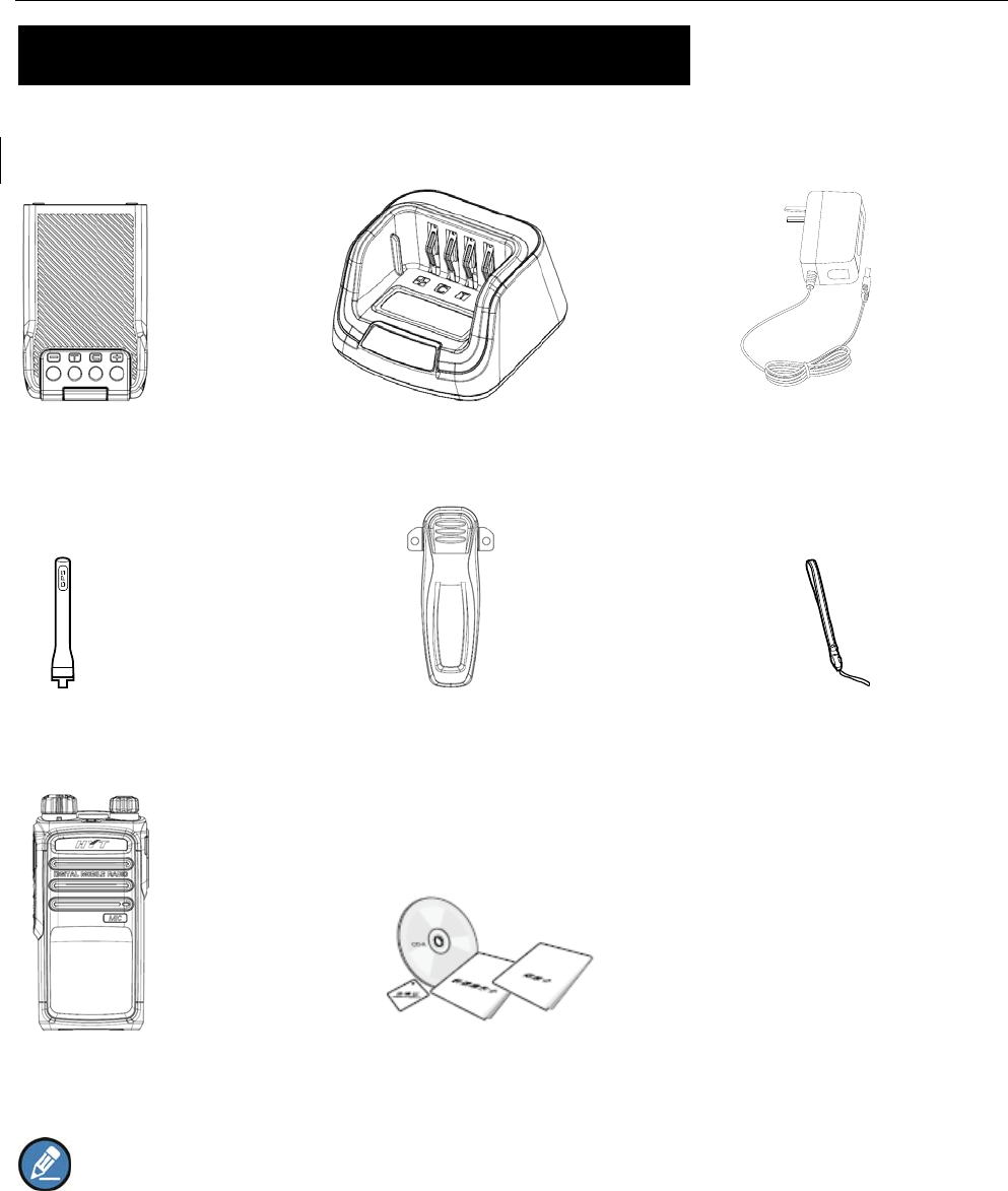
Checking Items in the Package
Please unpack carefully and check that all items listed below are received. If any item is missing or
damaged, please contact your dealer.
Battery Charger Power Adapter
Antenna Belt Clip Strap
Radio Unit CD
Owner’s Manual/ Safety Information Booklet/ Quick Reference Guide
Note: The antenna may vary with different frequency bands. And the frequency band is marked on
the label of antenna; if not, please refer to the label on the radio unit for frequency band information.
9
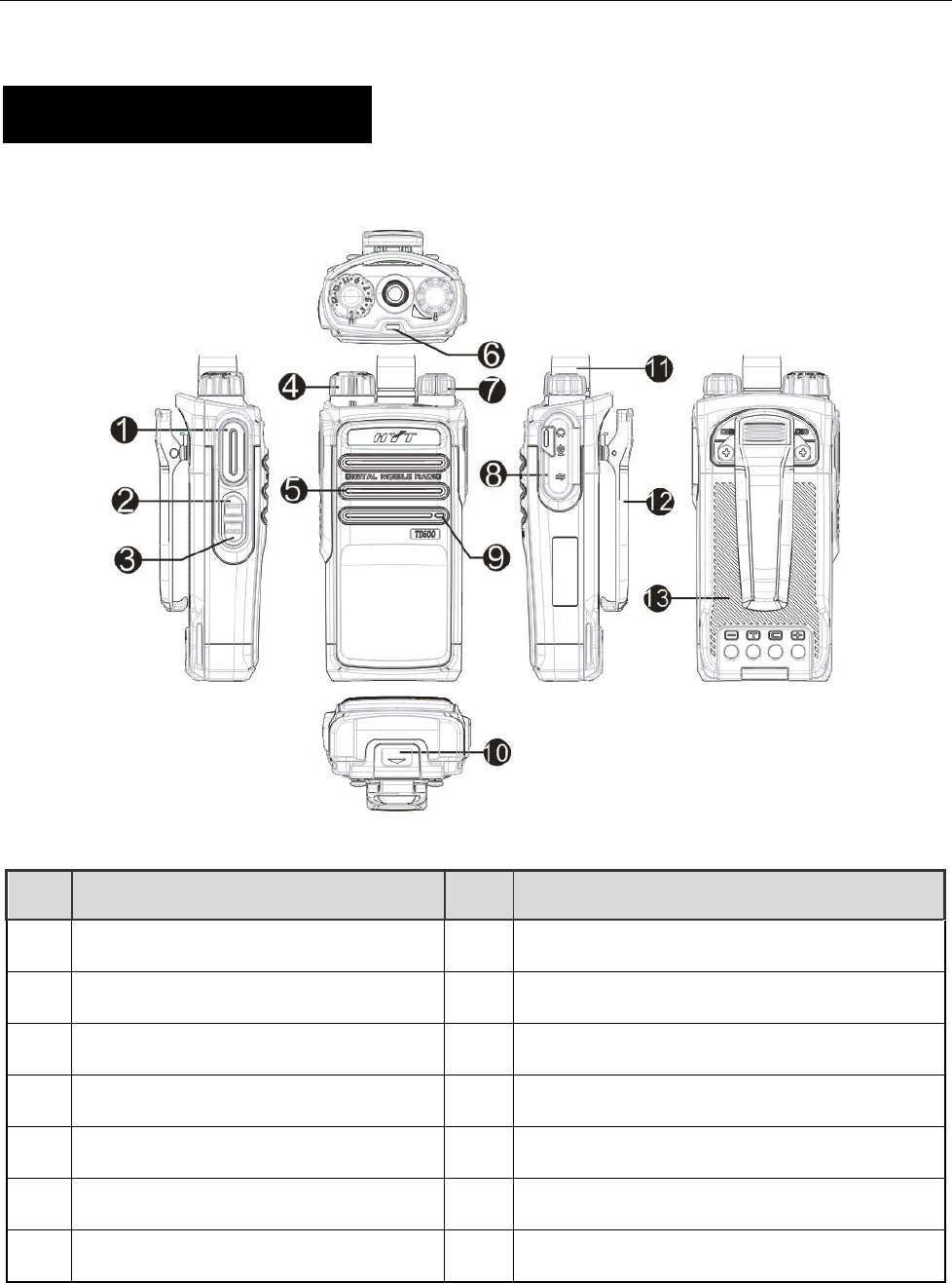
Product Overview
PD41X Product Controls
NO. PART NAME NO. PART NAME
○
1 PTT KEY ○
8 Accessory Jack
○
2 SK1(Side KEY) ○
9 Microphone
○
3 SK2(Side KEY) ○
10 Battery Latch
○
4 Channel Selector Knob ○
11 Antenna
○
5 Speaker ○
12 Belt Clip
○
6 LED Indicator ○
13 Battery
○
7 Radio On-Off/ Volume Control Knob
10
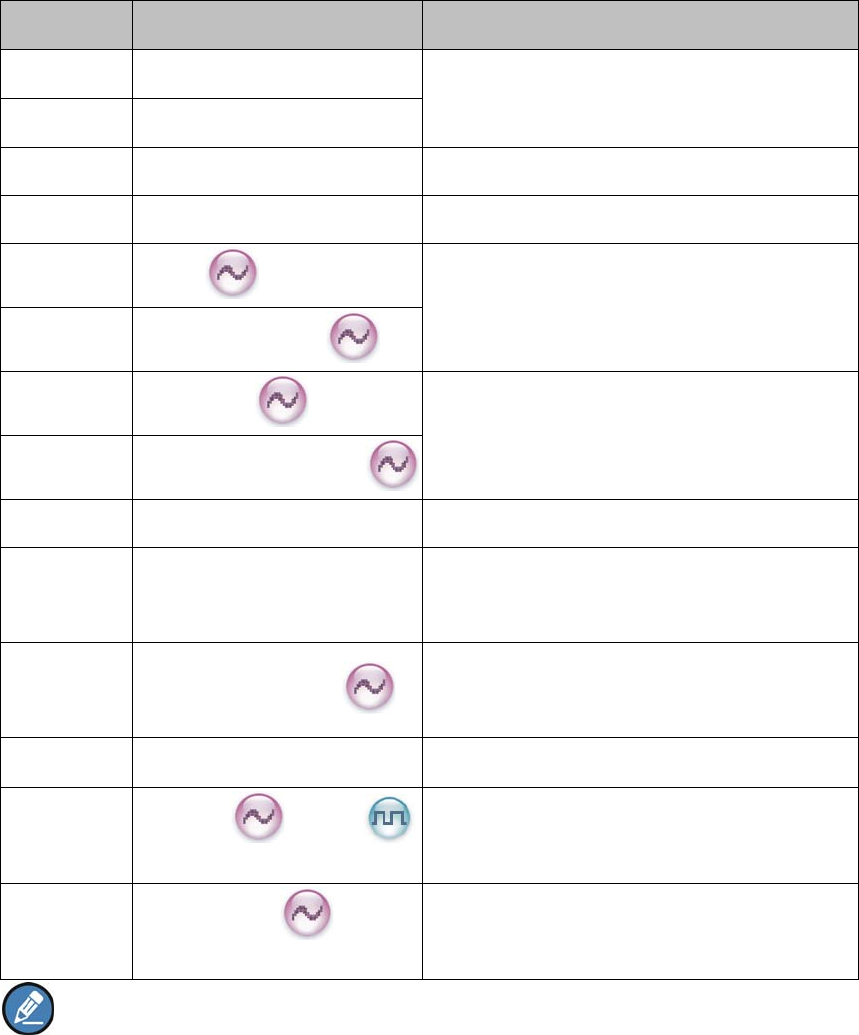
Programmable Keys
For enhanced convenience, you may request your dealer to program the keys SK1 or SK2 as shortcuts
to the functions listed below:
No. Shortcut Keys Description
1 Zone Up To select a desired zone quickly
2 Zone Down
3 Adjust Power Level To adjust power level quickly
4 Talk Around To directly communicate with other radios
5 Monitor To adjust the condition for incoming signal
match
6 Monitor Momentary
7 Squelch Off To always unmute speaker no matter whether
carrier is present or not
8 Squelch Off Momentary
9 Scan To receive signals on other channels
10 Nuisance Temporary Delete To temporarily ignore unwanted channel
activity
11 Adjust Squelch Level
To temporarily adjust the squelch threshold
required for the radio to unmute
12 Battery Power Indicator To indicate the battery strength
13 Scrambler /Encrypt To encrypt your voice so as to guarantee
privacy of your communication
14 Smart Call 1-5
To send voice-free signaling (dedicated for
5-Tone)
Note:
(1) Long and short press of a key can be assigned with different functions by your dealer.
(2) The SK1 is programmed as the Battery Power Indicator key by default, and is programmable by
your dealer.
11
Before Use
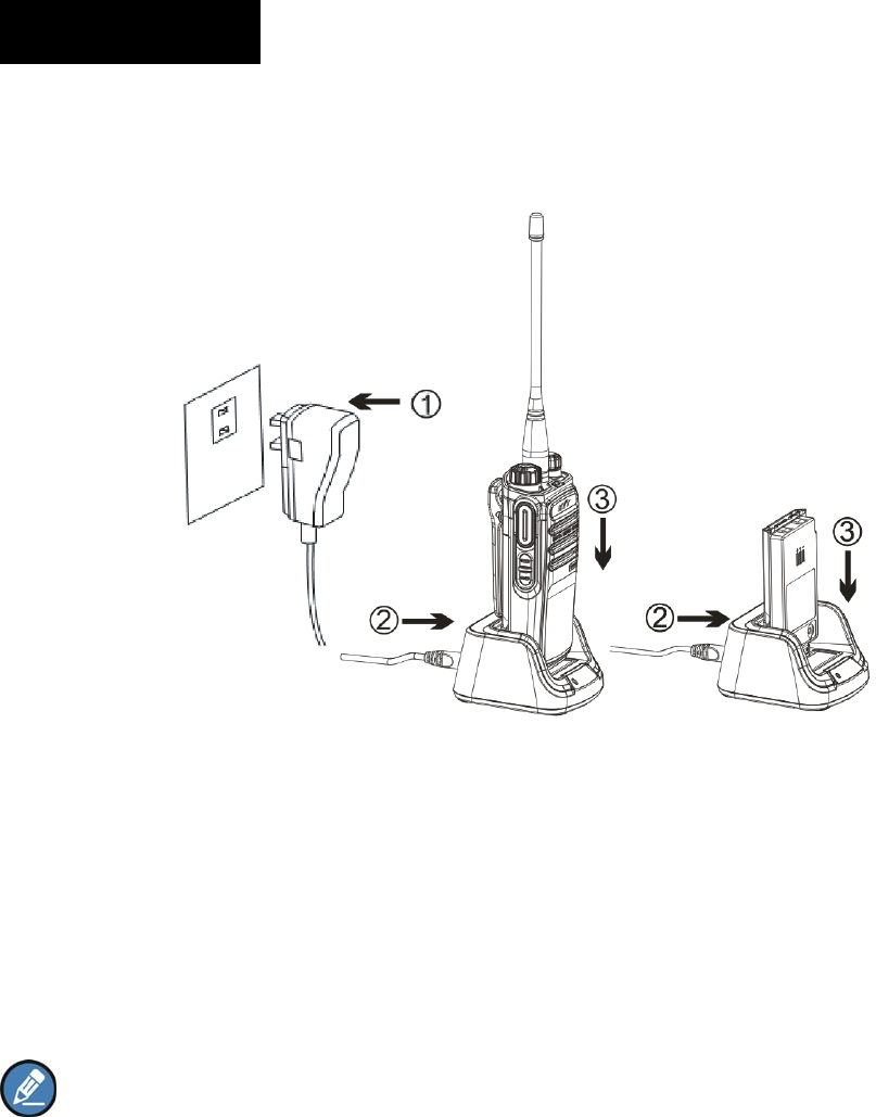
Charging the Battery
Use only the charger and battery specified by Hytera. Charger LED can indicate the charging process.
Procedures
1. Connect the power adapter to AC source. See arrow ①.
2. Plug the power adapter into the rear socket of the charger. See arrow ②.
3. Place the radio with the battery attached, or the battery alone, into the charger.
4. The charging process initiates when LED glows red, and is completed when LED glows green.
Note: To achieve optimal battery performance, please charge the battery for 5 hours before initial
use.
Charge Indicator
12
LED Indicator Charge Status
Red LED flashes slowly. Standby (no load)
Red LED glows. Charging
Orange LED glows. 90% charged
Green LED glows. Fully charged
Red LED flashes rapidly. Failure
Caution: Be sure to read the Safety Information Booklet, to get necessary safety information.
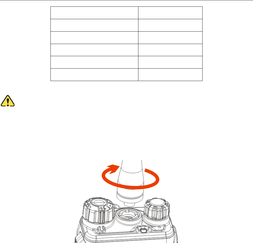
Attaching the Antenna
Turn the antenna clockwise to fasten it.
To remove the antenna, rotate it counter-clockwise.
Attaching the Battery
1. Insert the battery into top of the radio. See arrow ○
1.
2. Slightly press the bottom of the battery until a click is heard. See arrow ○
2.
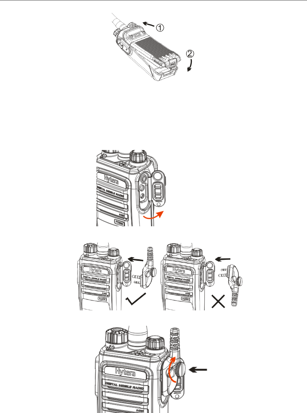
13
To remove the battery, turn off the radio first. Then slide the battery latch upwards to unlock the battery.
Attaching the Audio Accessory/Programming Cable
1. Open the accessory jack cover as the arrow shown.
2. Align the plug with the accessory jack.
3. Tighten the screw on the plug.
To remove accessories, loosen the screw.

14
Caution: When you are using an external accessory, waterproof performance of the radio may get
affected.

15
Status Indication
LED Indicator
The top LED indicator will help you easily identify the current radio status.
LED Indicator Radio Status
LED flashes green. Powering on
LED flashes red Powering off
LED glows red. Transmitting
LED glows green. Receiving
LED flashes green slowly. Scanning
LED glows orange. Call ended (within the preset time period)

16
Basic Operations
Turning the Radio On/Off
PD41X: Rotate the Radio On-Off/Volume Control knob clockwise/counter-clockwise until a click is
heard to turn the radio on/off.
Adjusting the Volume
PD41X: After turning the radio on, rotate the Radio On-Off/Volume Control knob clockwise to increase
the call volume, or counter-clockwise to decrease it.
Selecting a Zone
A zone is a group of channels exhibiting the same property, and is programmed by your dealer. The radio
supports 3 zones: Zone 1, Zone 2 and Zone 3. Each zone contains 16 channels at most.
You may quickly toggle to your desired zone by pressing the programmed Zone Up or Zone Down key.
In the process, you will hear one alert tone for Zone 1, two alert tones for Zone 2 and three alert tones for
Zone 3.
Selecting a Channel
After turning the radio on, rotate the Channel Selector knob to select a desired channel.
Switching the Channel Mode
Each channel can be programmed as either analog channel or digital channel. If the current zone
includes both analog and digital channels, you may quickly switch between digital and analog through the
Channel Selector knob.

17
Call
To ensure optimal volume of the receiving radio, hold the radio approximately 2.5 to 5 centimeters away
from your mouth.
Private Call
Transmitting a Private Call
In standby mode, hold down the PTT key to transmit a Private Call to the Private Call contact preset for
the current channel.
Note: Your dealer may preset a contact for each digital channel. The preset contact could be a
Private Call contact, a Group Call contact or an All Call contact.
Receiving and Responding to a Private Call
When a Private Call is received, you can listen to it without any operation, and you may hold down the
PTT key within the preset time period to call back.
Group Call
Transmitting a Group Call
In standby mode, hold down the PTT key to transmit a Group Call to the Group Call contact preset for the
current channel.
Receiving and Responding to a Group Call
When a Group Call is received, you can listen to it without any operation, and you may hold down the
PTT key within the preset time period to call back.
All Call
Transmitting an All Call
In standby mode, hold down the PTT key to transmit an All Call to the All Call contact preset for the
current channel.
Note: You can transmit an All Call only when it is enabled by your dealer.
Receiving an All Call
When an All Call is received, you can listen to it without any operation.

18
Note: You cannot respond to an All Call.
Calls on Analog Channels
To transmit on an analog channel, hold down the PTT and speak into the microphone. To receive, release
the PTT key.

19
Functions and Operations
Adjust Power Level
With this feature, you may switch power levels quickly. Generally, we recommend you to adopt low power
for battery saving. However, if you cannot communicate with radios located at a distant place with low
power, please select high power.
Operation:
Press the programmed Adjust Power Level key to switch between high power and low power (from low
power to high power: a high-pitched tone sounds; from high power to low power: a low-pitched tone
sounds).
Scan
This feature allows you to listen to communication activities on other channels so that you can keep a
close track of your team members.
Operation:
1. To enable the feature, press the programmed Scan key in standby mode (a high-pitched tone
sounds); or
Switch to a channel on which the feature “Auto Scan” is enabled via the programming software.
2. After the feature is enabled, your radio will scan according to the scan list set for the channel on
which scanning starts. The scanning process is as follows:
During scanning, the LED flashes orange.
When activities are detected on a channel, the radio will stay on the channel to receive current
activities, and the LED glows green.
If you don’t want to hear activities on the channel, press the programmed Nuisance Temporary
Delete key to remove the channel from the scan list temporarily.
If you want to continue staying on the channel, press the programmed Monitor or Squelch Off
key during scan stay.
3. To exit the scanning process, press the programmed Scan key again (a low-pitched tone sounds).

20
Talk Around
This feature allows you to continue communication even when the repeater malfunctions, or when your
radio is out of the repeater’s range but within the coverage range of other radios.
Operation:
Press the programmed Talk Around key to enable the feature (a high-pitched tone sounds). To disable
the feature, press this key again (a low-pitched tone sounds).
Monitor
To adjust match conditions for signal receiving, you can enable the feature “Monitor”.
Operation:
Press the programmed Monitor key to enable the feature (a high-pitched tone sounds). To disable
the feature, press this key again (a low-pitched tone sounds).
Hold down the programmed Monitor Momentary key to enable the feature (a high-pitched tone
sounds). To disable the feature, release this key (a low-pitched tone sounds).
Squelch Off
If the feature “Squelch Off” is enabled, the speaker will keep unmuted no matter whether carrier is
present.
Operation:
Press the programmed Squelch Off key to enable the feature, and the radio sounds background
noise (a high-pitched tone sounds). To disable the feature, press this key again (a low-pitched tone
sounds).
Hold down the programmed Squelch Off Momentary key to enable the feature, and the radio
sounds background noise (a high-pitched tone sounds). To disable the feature, release this key (a
low-pitched tone sounds).
Adjust Squelch Level
This feature allows you to adjust the squelch threshold required for the radio to unmute.
Generally, “Tight” is used in high noise environment. It requires stronger signal for the radio to unmute.
21
If the squelch level is set to Open, the speaker will keep unmuted irrespective of the satisfaction of
decoding conditions.
Operation:
Press the programmed Adjust Squelch Level key to switch among Tight, Open and Normal (from Tight
to Open, a low-pitched tone and background sound are heard; from Open to Normal, a high-pitched tone
is heard and the background sound disappears; from Normal to Tight, a high-pitched tone is heard).
Battery Power Indicator
This feature allows you to know the current battery strength.
Operation:
Hold down the programmed Battery Strength Indicator key, and the radio will give a specific indication
to represent the current battery strength. Release the key to exit.
Indication Battery Strength
Green LED glows. High
Orange LED glows. Medium
Red LED glows. Low
Red LED glows and the low
battery alert sounds.
Insufficient
Scrambler /Encrypt
The Scrambler/Encrypt feature can encrypt your audio signals to prevent eavesdropping. Thus privacy of
your communication is guaranteed.
Operation:
Press the programmed Scrambler/Encrypt key to enable Scrambler or Encrypt on the current
channel (a high-pitched tone sounds); press the key again to disable the feature (a low-pitched tone
sounds).
If the Scrambler/Encrypt feature is enabled for a channel via the programming software, switch to the
channel to enable the feature, or exit the channel to disable the feature.
Busy Channel Lockout
If enabled via the programming software, this feature can prevent your radio interfering with other
transmitting radios on the same channel. If you hold down the PTT key while the channel is in use, your
radio will keep beeping, alerting you to transmission prohibition. To stop beeping, please release the PTT

22
key. When the channel is free, you can press and hold down the PTT key to transmit.
Time-out Timer (TOT)
The purpose of TOT is to prevent any user from occupying a channel for an extended period. If the preset
time expires, the radio will automatically terminate transmission and keep beeping. To stop beeping,
please release the PTT key. You must wait for a certain time period (preset by your dealer) to initiate
another transmission.
If the pre-alert function is set by your dealer, your radio will alert you to the TOT expiration in advance.
Pseudo Trunking
This feature can be enabled via the programming software. If your radio operates on a channel with this
feature enabled and one time slot is already occupied, it can transmit and receive on the other free time
slot, allowing you to communicate timely under emergent situations.
MIC AGC
If enabled via the programming software, your radio will process the audio signals during transmission,
providing improved audio for the receiving radio.
Radio Registration Service
If enabled via the programming software, your radio will automatically register in the system within a
certain period after power-on. Then it can acquire online information of other radios via accessing specific
servers within the valid registration period.

23
Troubleshooting
Phenomena Analysis Solution
The radio can not be
powered on.
The battery may be
improperly installed. Remove the battery and attach it again.
The battery may run out. Recharge or replace the battery.
The battery may suffer from
poor contact caused by
dirtied or damaged battery
contacts.
Clean the battery contacts. If the problem
can not be solved, contact your dealer or
authorized service center for inspection and
repair.
During receiving
signals, the voice is
weak, discontinuous or
totally inactive.
The battery strength may be
too low. Recharge or replace the battery.
The volume may be set to a
low level. Increase the volume.
The antenna may get loose
or may be improperly
installed.
Power off the radio, and re-install the
antenna.
The speaker may be
blocked or damaged.
Clean surface of the speaker. If the problem
can not be solved, contact your dealer or
authorized service center for inspection and
repair.
You can not
communicate with
other members.
The frequency or signaling
may be inconsistent with
that of other members.
Set your TX/RX frequency and signaling to
the same as that of other members.
The channel type
(digital/analog) may be set
inconsistently.
Make sure all members are on the same
digital/analog channel.
You may be too far away
from the group members. Move towards other members.

24
Irrelevant
communication or
noise is heard on the
channel.
You may be interrupted by
radios using the same
frequency.
Change the frequency, or adjust the squelch
level.
The radio may be set with
no signaling.
Set signaling for all member radios to avoid
interference at the same frequency.
The noise is too loud.
You may be too far away
from other members. Move towards other members.
You may be at an
unfavorable position. For
example, your
communication may be
blocked by high buildings or
frustrated in the
underground areas.
Move to an open and flat area, and restart
the radio.
You may suffer from
external disturbance (such
as electromagnetic
interference).
Stay away from equipment that may cause
interference.
If the above solutions can not fix your problems, or you may have some other queries, please contact us
or your local dealer for more technical support.

25
Care and Cleaning
To guarantee optimal performance as well as a long service life of the product, please follow the tips
below.
Product Care
Do not pierce or scrape the product with any edged instruments or hard objects.
Keep the product far away from substances that can corrode the circuit.
Do not hold the product by its antenna or earpiece cable directly.
Attach the accessory jack cover when the product is not in use.
Product Cleaning
Clean up the dust and fine particles on the product surface and charging piece with a clean and dry
lint-free cloth or a brush regularly.
Use neutral cleanser and a non-woven fabric to clean the keys, control knobs and front case
long-time use. Do not use chemical preparations such as stain removers, alcohol, sprays or oil
preparations, so as to avoid surface case damage. Make sure the product is completely dry before
use.
Caution: Power off and remove the battery before cleaning.
26
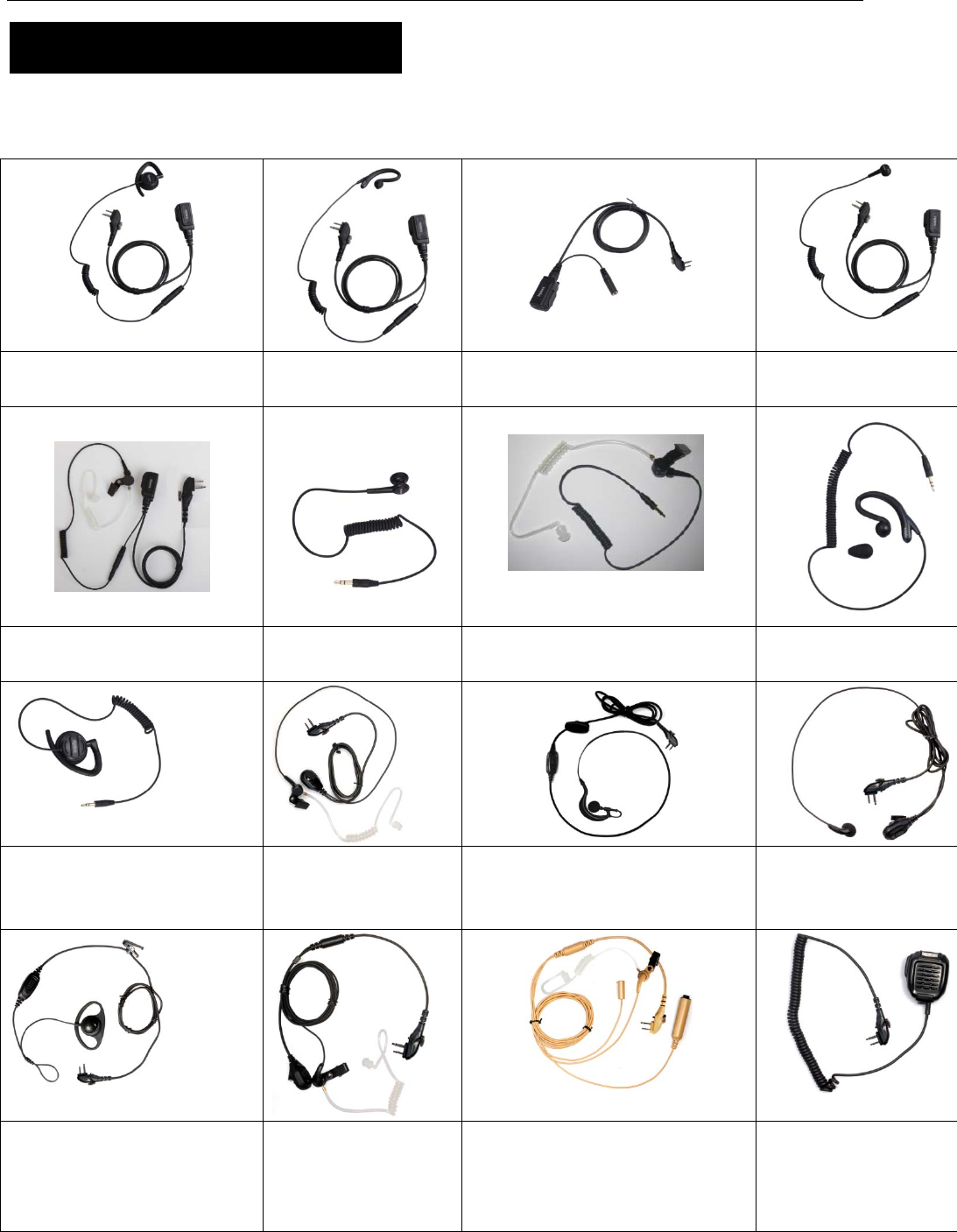
Optional Accessories
The following items are the main optional accessories for the product, and please consult your local
dealer for more other accessories.
Remote Swivel Earset EHM20 Remote C-Earset
EHM19
PTT&MIC cable(for use with
Receive-Only Earpiece) ACM-01
Earbud with remote
on-mic PTT ESM14
Earpiece with Transparent
Acoustic Tube EAM17
Receive-Only Earbud
ES-01
Receive-Only Earpiece with
Transparent Acoustic Tube ES-02
Receive-Only C Style
Earloop EH-01
Receive-Only Ajustable
Earhook with Swivel Speaker
EH-02
Earbud with on-mic
PTT EAM12
Earset with in-line PTT EHM18 Earbud with on-mic PT
T
ESM12
D-Earset with in-line PTT
EHM15
2-wire Surveillance
Earpiece with
Transparent Acoustic
Tube (black) EAM13
3-wire Surveillance Earpiece with
Transparent Acoustic Tube
(beige) EAM15
Remote speaker
microphone SM08M3
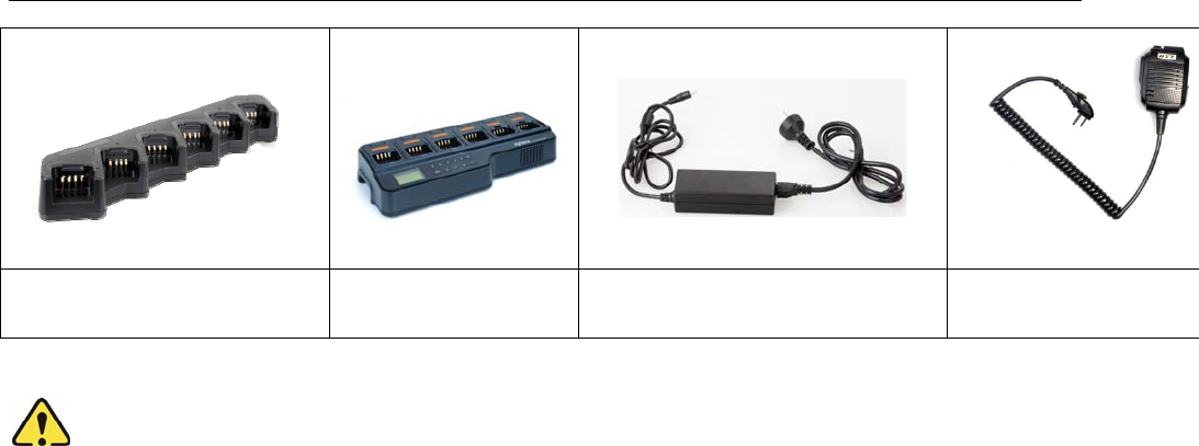
27
MCU Multi-unit Rapid-rate Charger
(for Li-Ion/Ni-MH batteries) MCA08
Battery Analyzer MCA05 PS7501 AC/DC Adapter Remote speaker micropho
n
(IP55) SM13M1
Caution: Use the accessories specified by Hytera only. If not, Hytera shall not be liable for any
losses or damages arising out of use of unauthorized accessories.