Hytera Communications PD48XUV DIGITAL PORTABLE RADIO User Manual
Hytera Communications Corporation Limited DIGITAL PORTABLE RADIO Users Manual
User manual
Preface
Thanks for your favor in our product. This manual is helpful for you to quickly know how to use the
product. To avoid body injury or property loss caused by misoperation, please read the Safety
Information Booklet carefully before use.
This manual is applicable to the following product:
PD48X Digital Portable Radio (X may represent 2, 5, 6 or 8).

Icon Conventions
: Indicates functions that are available on digital channel only.
: Indicates functions that are available on analog channel only.
Functions marked with no icon are available on both analog and digital channels.
Disclaimer
Hytera Communications Corporation Limited (the Company) endeavors to achieve the accuracy and
completeness of this manual, but no warranty of accuracy or reliability is given. All the specifications and
designs are subject to change without notice due to continuous technology development. No part of this
manual may be copied, modified, translated, or distributed in any manner without the express written
permission of us.
We do not guarantee, for any particular purpose, the accuracy, validity, timeliness, legitimacy or
completeness of the Third Party products and contents involved in this manual.
If you have any suggestions or would like to learn more details, please visit our website at:
http://www.hytera.com.
RF Radiation Information
This product must be restricted to operations in an occupational/controlled RF exposure environment.
Users must be fully aware of the hazards of the exposure and able to exercise control over their RF
exposure to qualify for the higher exposure limits.
RF Radiation Profile
Radio Frequency (RF) is a frequency of electromagnetic radiation in the range at which radio signals are
transmitted. RF technology is widely used in communication, medicine, food processing and other fields.
It may generate radiation during use.
RF Radiation Safety
In order to ensure user health, experts from relevant industries including science, engineering, medicine
and health work with international organizations to develop standards for safe exposure to RF radiation.
These standards consist of:
United States Federal Communications Commission, Code of Federal Regulations; 47CFR part 2
sub-part J;
American National Standards Institute (ANSI)/Institute of Electrical and Electronic Engineers (IEEE)
C95. 1-1992;
Institute of Electrical and Electronic Engineers (IEEE) C95.1-1999;
International Commission on Non-Ionizing Radiation Protection (ICNIRP) 1998;
FCC Regulations
Federal Communication Commission (FCC) requires that all radio communication products should meet
the requirements set forth in the above standards before they can be marketed in the U.S, and the
manufacturer shall post a RF label on the product to inform users of operational instructions, so as to
enhance their occupational health against exposure to RF energy.
Operational Instructions and Training Guidelines
To ensure optimal performance and compliance with the occupational/controlled environment RF energy
exposure limits in the above standards and guidelines, users should transmit not more than 50% of the
time and always adhere to the following procedures:
RF energy will be generated only when the radio is transmitting.
The radio must be at least 2.5 centimeters away from human body when transmitting.
Warning! : This DIGITAL PORTABLE RADIO generates RF electromagnetic energy during transmit
mode. This radio is designed for and classified as “Occupational Use Only,” meaning it must be used
only during the course of employment by individuals aware of the hazards and the ways to minimize
such hazards. This radio is NOT intended for use by the “General Population” in an uncontrolled
environment.
EU Regulatory Conformance
As certified by the qualified laboratory, the product is in compliance with the essential requirements and
other relevant provisions of the following directives:
1999/5/EC.
Please note that the above information is applicable to EU countries only.

Contents
1. Items in the Package ............................................................................................................................ 1
2. Product Overview ................................................................................................................................. 2
2.1 Product Controls ............................................................................................................................... 2
2.2 Programmable Keys ......................................................................................................................... 2
3. Before Use............................................................................................................................................. 3
3.1 Attaching the Battery ........................................................................................................................ 3
3.2 Attaching the Antenna ...................................................................................................................... 4
3.3 Attaching the Belt Clip ...................................................................................................................... 4
3.4 Attaching the Accessories ................................................................................................................ 4
3.5 Charging the Battery ......................................................................................................................... 6
4. Status Indications ................................................................................................................................ 8
4.1 LCD Icon ........................................................................................................................................... 8
4.2 LED Indicator .................................................................................................................................... 9
5. Menu Navigation ................................................................................................................................. 10
6. Basic Operations ................................................................................................................................ 11
6.1 Turning the Radio On/Off ............................................................................................................... 11
6.2 Adjusting the Volume ...................................................................................................................... 11
6.3 Selecting a Zone ............................................................................................................................. 11
6.4 Selecting a Channel........................................................................................................................ 11
6.5 Locking and Unlocking the Keypad ................................................................................................ 11
7. Call Services ....................................................................................................................................... 13
7.1 Call on Digital Channel ............................................................................................................. 13
7.2 Call on Analog Channel .......................................................................................................... 14
8. Features and Operations ................................................................................................................... 15
8.1 Home Screen .................................................................................................................................. 15
8.2 Managing the Contact ............................................................................................................. 15
8.3 Message .................................................................................................................................. 15
8.4 Call Log ................................................................................................................................... 16
8.5 Scan ................................................................................................................................................ 17
8.6 Setting the Radio ............................................................................................................................ 18
8.7 Device Information .......................................................................................................................... 20
8.8 One Touch Call ....................................................................................................................... 20
8.9 Time-out Timer (TOT) ..................................................................................................................... 21
8.10 Busy Channel Lockout .................................................................................................................. 21
8.11 Monitor ................................................................................................................................... 21

8.12 CTCSS/ CDCSS ..................................................................................................................... 21
8.13 Squelch Off .............................................................................................................................. 22
8.14 TDMA Direct Mode ................................................................................................................. 22
8.15 VOX .............................................................................................................................................. 22
8.16 CDC/CTC Selected ................................................................................................................ 23
9. Troubleshooting ................................................................................................................................. 24
10. Care and Cleaning ............................................................................................................................ 26
11. Optional Accessories....................................................................................................................... 27
12. FCC STATEMENT ............................................................................................................................. 28
1
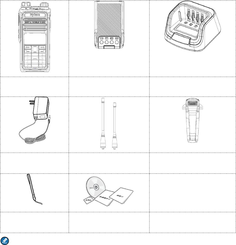
1. Items in the Package
Please unpack carefully and check if all items listed below are received. If any item is missing or
damaged, please contact your dealer.
Radio
Battery
Charger
Power Adapter
Antenna
Belt Clip
Strap
Documentation Kit
Note
1.The frequency band is marked on the label of antenna; if not, please refer to the label on the radio
for frequency band information.
2. The long antenna operation frequency range is 350MHz to 400MHz, When the frequency in this
range, use long antenna. The short antenna operation frequency range is 400MHz to 470MHz,
When the frequency in this range, use short antenna.
2
2. Product Overview
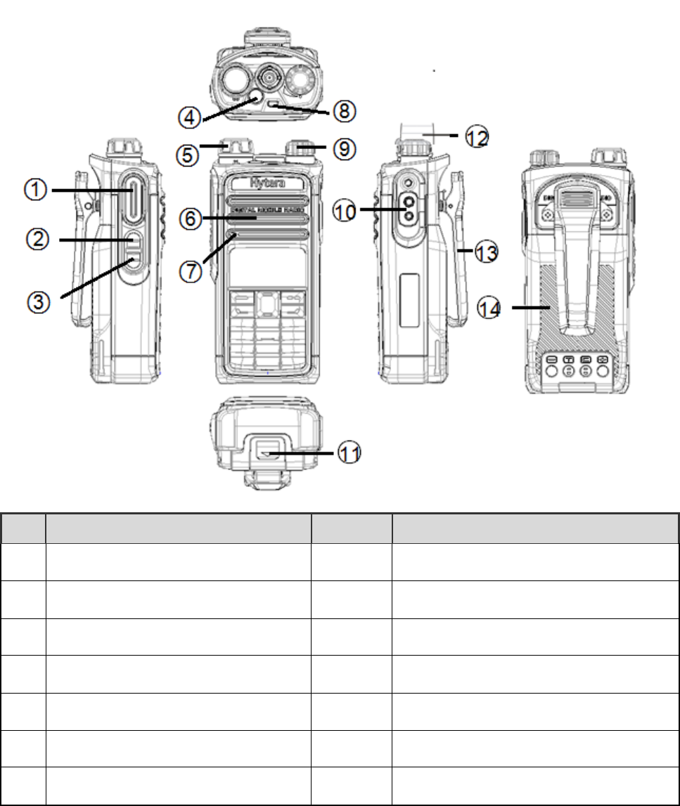
2.1 Product Controls
No.
Part Name
No.
Part Name
○
1
PTT (Push-to-Talk) Key
○
8
LED Indicator
○
2
SK1 (Side Key 1)
○
9
Power On/Off/Volume Control Knob
○
3
SK2 (Side Key 2)
○
10
Accessory Connector
○
4
Call Key(programmable)
○
11
Battery Latch Call End Key
○
5
Channel Selector Knob
○
12
Antenna
○
6
LCD Display Speaker
○
13
Belt Clip
○
7
Microphone
○
14
Battery
2.2 Programmable Keys
For enhanced convenience, you may request your dealer to program the SK1, SK2, P1, P2 and P3 keys
as shortcuts to certain feature.
3
3. Before Use
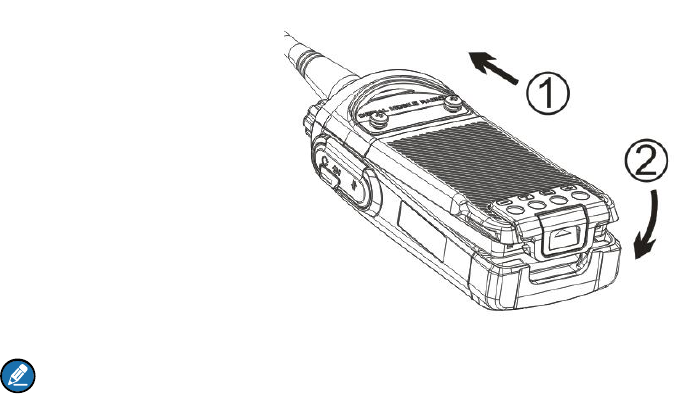
3.1 Attaching the Battery
To attach the battery, do as follows.
Note
To remove the battery, please turn off the radio first. Then slide the battery latch upwards to unlock
the battery.
4
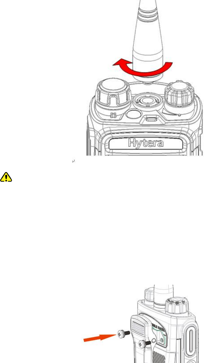
3.2 Attaching the Antenna
Caution
Do not hold the radio by its antenna, otherwise the performance and lifespan of the antenna will be
reduced.
3.3 Attaching the Belt Clip
To attach the belt clip, do as follows.
Step 1 Remove the screws.
Step 2 Align the screw holes on the belt clip with those on the radio’s back, and then tighten the
screws.
3.4 Attaching the Accessories
Step 1 Open the accessory connector cover as shown below.
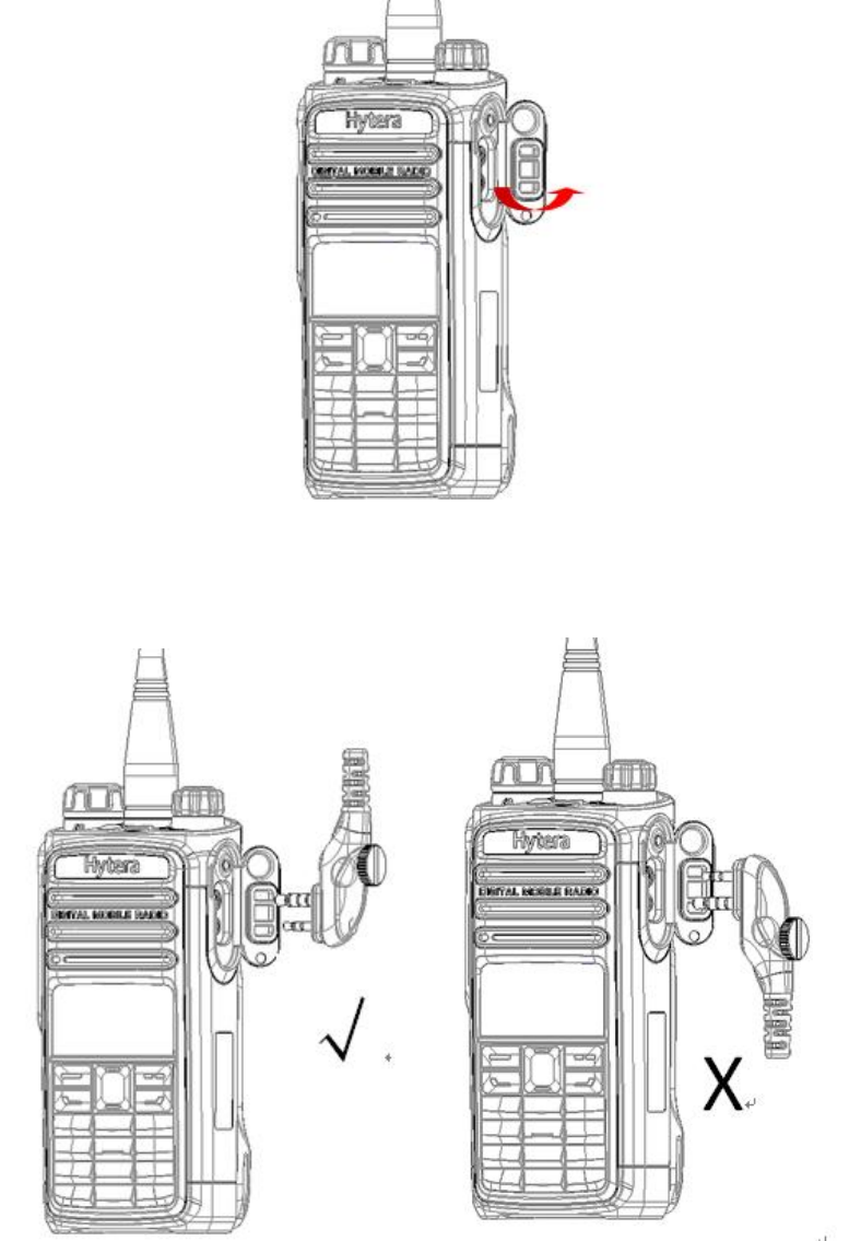
5
Step 2 Align the accessory (such as an audio accessory, or a programming cable) plug with the
accessory connector.
Step 3 Tighten the screw on the plug.
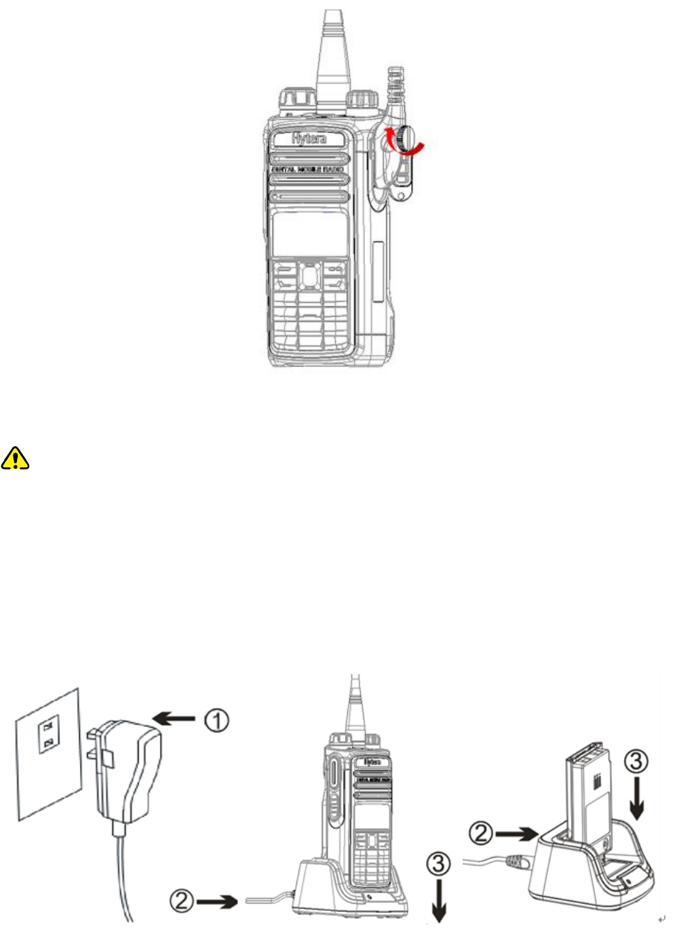
6
3.5 Charging the Battery
Caution
Make sure the radio is powered off before charging. Read the Safety Information Booklet in
advance to get necessary safety information.
Charge a new battery for at least 5 hours before initial use for best performance.
Please use the charger specified by the Company to charge the battery. Charging Diagram is listed
below.
Charging the radio (with battery attached) Charging the battery
Charging Status Indication (on charger):

7
LED Indication
Charging Status
The LED Indicator
flashes red slowly.
Standby (no load)
The LED Indicator
glows red.
Charging
The LED Indicator
glows orange.
90% charged
The LED Indicator
glows green.
Fully charged
The LED Indicator
flashes red rapidly.
Charging failure
8
4. Status Indications
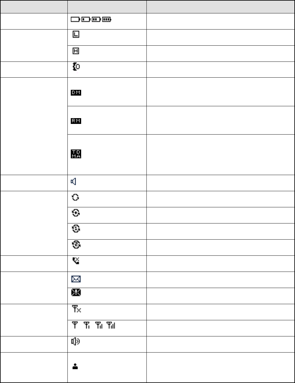
4.1 LCD Icon
Name
Icon
Radio Status
Battery Power Icon
More bars indicate more battery power.
TX Power Icon
Low TX power for the current channel.
High TX power for the current channel.
Accessory Icon
An accessory is connected.
Operation Mode Icon
Direct Mode: Under this mode, the radio can
communicate with each other directly.
Repeater Mode: Under this mode, the radio can
communicate with each other via a repeater.
TDMA Direct Mode: Under this mode, two
individual calls can be supported simultaneously
on the 12.5 kHz channel.
Monitor Icon
The Monitor feature is active.
Scan Icon
The radio is scanning.
The radio stays on a non-priority channel.
The radio stays on priority channel 1.
The radio stays on priority channel 2.
Missed Call Icon
Missed call(s).
Message Icon
New message/unread message.
Inbox is full.
RSSI Icon
No signal.
More bars indicate stronger signal strength.
Speaker Icon
The speaker is unmuted.
Call/Contact Icon
Indicates a private call in progress.
Indicates a private contact in the contact list.
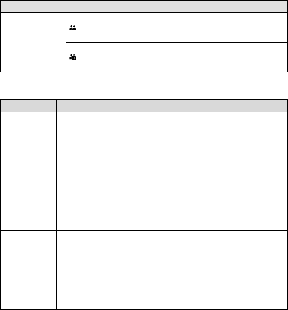
9
Name
Icon
Radio Status
Indicates a group call in progress.
Indicates a group contact in the contact list.
Indicates an all call in progress.
Indicates an all call contact in the contact list.
4.2 LED Indicator
LED Indication
Radio Status
The LED
indicator flashes
green.
Powering on
The LED
indicator glows
green.
Receiving
The LED
indicator glows
red.
Transmitting
The LED
indicator flashes
orange slowly.
Scanning
The LED
indicator glows
orange.
Call hang time. No voice is being transmitted or received on the traffic channel
during a call. Within such period, you can hold down the PTT key to talk to the
other party.
10
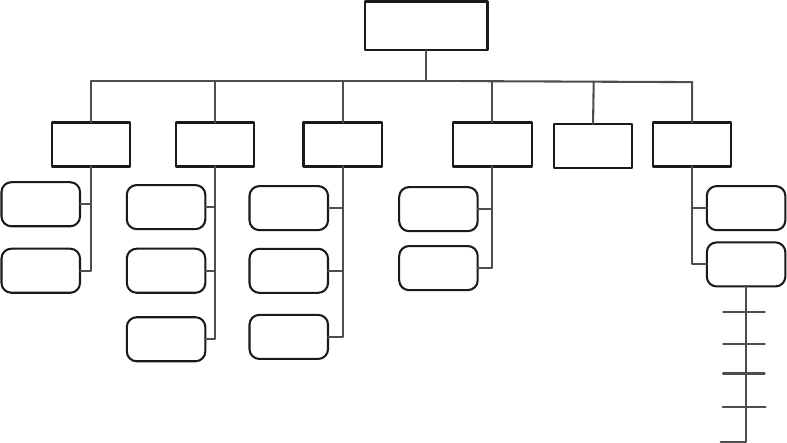
5. Menu Navigation
The following diagram outlines the menu structure of the radio. You can personalize menu option
displayed in the radio via your dealer.
To select and confirm the options shown in the menu, press the OK/Menu key and then press the Up or
Down key to select your needed option, finally press the OK/Menu key. This manual only describes the
paths to the menus in terms of menu operations, for example, to access the contact list, go to “Menu ->
Contact -> Contact List”.
The radio supports menu reset function. If you do not operate the menu for a predefined time period set
by the dealer, the radio will automatically return to the home screen. You may request your dealer to
configure the auto reset time or disable the feature.
Menu
Contact Message Call Logs Settings
Zone
Contact
List
Favorite
Contact Quick Text
Outbox
Inbox
Outgoing
Incoming
Missed
Keypad
Lock
Power Level
Radio Set
Backlight
Device Info
Tones
LEDCovert Mode
Scan List
Scan
Scan
On/Off
Talk
Around
Adjust Squelch Level
VOX
11
6. Basic Operations
6.1 Turning the Radio On/Off
To turn on the radio, rotate the Power On/Off/Volume Control knob clockwise until you hear a click. To
turn off the radio, rotate the knob counter-clockwise until you hear a click.
If the Channel Notify upon Power-on feature is enabled by your dealer, the radio will announce the
channel number upon power-on.
6.2 Adjusting the Volume
After the radio is powered on, you can rotate the Power On/Off/Volume Control knob clockwise to
increase the voice volume, and rotate the knob counter-clockwise to decease it.
6.3 Selecting a Zone
A zone is a group of channels with the same property, which can facilitate convenient management over
the channels. The radio supports 2 zones, each of which consists of up to 16 channels. You can select a
zone through any of the following ways:
Menu Operation: Go to “Menu -> Zone”, press the Up or Down key to select an appropriate zone,
and then press the OK/Menu key to confirm it.
Shortcut key: You can toggle to the appropriate zone by pressing the programmed Zone Up or Zone
Down key preset by your dealer.
If the Zone Notify feature is enabled by your dealer, the radio will announce the zone number when
selecting zone.
6.4 Selecting a Channel
After the radio is powered on, you can rotate the Channel Selector Knob to select an appropriate
channel.
If the Channel Notify feature is enabled by your dealer, the radio will announce the channel number upon
channel switching.
6.5 Locking and Unlocking the Keypad
When the keypad is not in use, you can lock the keypad to prevent accidental keypad operation. The
following methods are available for you to lock or unlock the keypad:

12
Key Combination: press the OK/Menu key and then press P1 to lock the keypad; press Any Key and
P1 to unlock it.
Note
Any Key cannot be PTT, SK1 and SK2 key.
Shortcut key: Press the programmed Keypad Lock key to lock or unlock the keypad.
Menu: Go to “Menu -> Settings -> Radio Set -> Keypad Lock” and then select “Enable” or “Disable”.
Enable: The keypad will be locked automatically if no operation is made within the preset time
period. However, you can unlock the keypad via the key combination or the programmed Keypad
Lock key mentioned above.
Disable: The keypad will not be locked automatically. However, you can lock or unlock the keypad
via the key combination or Keypad Lock key mentioned above.
13
7. Call Services
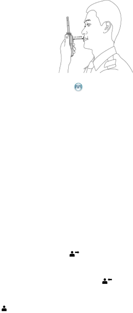
After the radio is powered on, you can make and receive calls. To ensure optimal volume of the
receiving radio, keep the microphone about 2.5 to 5 centimeters away from your mouth when the radio is
transmitting.
Private call: It is a voice call between one individual user and another individual user.
Group call: It is a voice call between one individual user and a predefined group of users. All parties
in the group can communicate with each other.
All call: It is a one-way voice call from any user to all users on a channel.
7.1 Call on Digital Channel
You can initiate a private call, group call or all call (programmed by your dealer) through the same
operations on digital channel. When calling back, the radio will make a call to the calling party in private
call; but in group call, the radio will make a call to all parties involved when calling back. And you cannot
call back in an all call.
Here takes the private call between Radio A and Radio B for example:
Preset contact
Step 1 Radio A and B select the same digital channel.
You may preset a regular private call/group call/all call contact for each digital channel via your
dealer.
Step 2 Radio A holds down the PTT key to initiate a call.
Step 3 By holding down the PTT key, Radio A can talk to the microphone when the LED indicator
glows red and the radio displays the icon .
Step 4 Radio B can receive the call without any operation. When the radio is receiving, the LED
indicator glows green and the radio displays the icon .
Step 5 Radio B can hold down the PTT key to talk when the LED indicator glows orange and the radio
displays the icon .

14
If you do not respond to it, the radio will provide appropriate indications.
Step 6 Radio A can receive the call without any operation. When the radio is receiving, the LED
indicator glows green and the radio displays the icon .
Step 7 Radio A can hold down the PTT key to talk when the LED indicator glows orange and the radio
displays the icon .
Contact List or Call Log
Step 1 Radio A and B select the same digital channel.
Step 2 Radio A accesses the contact list via menu “Menu -> Contact -> Contact List”, “Menu ->
Contact -> Favorite Contact” or “Menu -> Call Log -> Outgoing/Incoming/Missed”.
Step 3 Radio A presses the Up or Down key to select Radio B.
Step 4 Radio A holds down the PTT key to initiate a call.
Step 5 By holding down the PTT key, Radio A can talk to the microphone when the LED indicator
glows red and the radio displays the icon .
Step 6 Radio B can receive the call without any operation. When the radio is receiving, the LED
indicator glows green and the radio displays the icon .
Step 7 Radio B can hold down the PTT key to talk when the LED indicator glows orange and the radio
displays the icon .
If you do not respond to it, the radio will provide appropriate indications.
Step 8 Radio A can receive the call without any operation. When the radio is receiving, the LED
indicator glows green and the radio displays the icon .
Step 9 Radio A can hold down the PTT key to talk when the LED indicator glows orange and the radio
displays the icon .
Note
The Call Hang Time (the duration of LED indicator glowing orange) is preset by your dealer. If neither
party talks before this duration expires, the call will end.
7.2 Call on Analog Channel
The calling operations on the analog channel are the same as that on the digital channel. The difference
is that the called parties are all the users on the channel, rather than the preset contact for the channel.

15
8. Features and Operations
8.1 Home Screen
Description
This feature allows the radio to return to the home screen directly.
Operation
To return to the home screen directly, press .
8.2 Managing the Contact
Contact allows you to manage your contacts via the menu, for example, viewing contact’s information,
adding new contacts, setting the frequently-used contacts and deleting contacts.
8.2.1 Contact List
Description
The Contact List is used to save Private Call/Group Call/All Call contacts information which is preset by
the dealer.
Operation
Go to “Menu -> Contact -> Contact List” to access the contact list.
Press the programmed Contact List key to access the contact list.
Press to access the contact list.
Under this sub-menu, you can view the contact details.
8.2.2 Favorite Contact
Description
Favorite Contact allows you to add the frequently used contacts from Contact List.
Operation
Go to “Menu -> Contact -> Favorite Contact” to access the favorite contact list.
In the “Favorite Contact” menu, you can check the contact information or delete the contacts.
8.3 Message
You can send the Quick Text message directly. In the inbox, you can reply, forward or delete the text
message, and in the outbox you can also resend, forward or delete the message.
Go to “Menu -> Message” to configure the corresponding features.

16
8.3.1 Quick Text
Description
The radio supports a maximum of 10 Quick Text messages programmed by your dealer.
Operation
Go to “Menu -> Message -> Quick Text” and you can send the quick text directly.
8.3.2 Inbox
Description
The radio saves the received messages into the Inbox and gives every message a corresponding icon to
indicate its status.
: Read message.
: Unread message.
The inbox can save up to 10 received messages. When the Inbox is full, the icon will appear on the LCD,
and the earliest message will be overwritten by the latest one automatically.
Operation
Go to “Menu -> Message -> InBox” to enter the relevant screen.
8.3.3 Outbox
Description
The radio saves the sent messages into the Outbox.
The outbox can save up to 10 sent messages. When the OutBox is full, the earliest message will be
overwritten by the latest one automatically.
Operation
Go to “Menu -> Message -> OutBox” to enter the relevant screen.
8.4 Call Log
Description
The radio keeps track of all recent outgoing, incoming and missed private calls only.
The radio can save up to 10 call entries in the Outgoing/Incoming/Missed list respectively. When any list
is full, the earliest entry in the list will be overwritten by the latest one automatically.
Operation
Go to “Menu -> Call Log -> Outgoing/Incoming/Missed” to enter the relevant screen.
You can select a call log and hold down the PTT key to make a call; or select a call log to delete it.

17
8.5 Scan
Scan allows you to search for a channel with ongoing activities, and stay on it to listen to its
communication activities so that you can keep a track of related team members.
8.5.1 Activating the Scan feature
Description
With the Scan feature enabled, the radio will scan all the channels in the scan list set for the current
channel.
Operation
Go to “Menu -> Scan -> Scan On/Off -> On” to enable the Scan feature.
In the home screen, you can press the programmed Scan key to enable the Scan feature, or switch
to a channel on which the Auto Scan feature is enabled via the CPS to enable the Scan feature.
After the feature is enabled, the radio will scan all the channels in the scan list set for the channel on
which scanning starts. The scanning process is as follows:
Step 1 During scanning, the radio displays the icon , and the LED indicator flashes orange slowly.
Step 2 When activities are detected on a channel, the radio will stay on the channel to receive current
activities, and the LED indicator will glow green.
If the radio stays on a non-priority channel, the radio will display the icon .If the radio stays
on Priority Channel 1 or Priority Channel 2, it will display the icon or respectively.
Step 3 If you don’t want to listen to the activities on the channel, press the programmed Nuisance
Temporary Delete key to remove the channel from the scan list temporarily. The removed channel will
not be scanned in subsequent scanning, but it will be restored into the scan list when the radio is
restarted.
Step 4 If you want to keep listening to the activities on the channel, press the programmed Monitor or
Squelch Off Momentary key during scan stay.
Note
The radio cannot scan analog channel and digital channel at the same time.
8.5.2 Deactivating the Scan feature
Description
With the Scan feature disabled, the radio will stop scanning all the channels in the scan list set for the
current channel.
Operation
Go to “Menu -> Scan -> Scan On/Off -> Off” to disable the Scan feature.
18
Press the programmed Scan key during scanning.
8.5.3 Setting the Scan List
Description
Scan List allows you to select the appropriate scan list.
Operation
Go to “Menu -> Scan -> Scan List” to select the appropriate scan list.
The radio can support up to 8 scan lists.
8.6 Setting the Radio
You can optimize performance of your radio via the following configuration according to your actual
needs and preferences.
Go to “Menu -> Settings -> Radio Set” to configure the corresponding features.
8.6.1 Talk Around
Description
You can continue to communicate in DMO by pressing the programmed Talk Around key when the
repeater malfunctions, or when the radio is out of the repeater’s coverage but still within the coverage of
the other radio.
Operation
Go to “Menu -> Settings -> Radio Set -> Talk Around” to switch to direct mode.
Press the programmed Talk Around key to enable the feature; press this key again to disable the
feature.
8.6.2 Power Level
Description
Power Level allows you to set the TX power level. High power can extend the signal coverage, enabling
you to communicate with farther radios. Generally, we recommend you to adopt low power for battery
saving.
Operation
Go to “Menu -> Settings -> Radio Set -> Power Level -> High/Low” to toggle the TX power level
between high and low.
Press the programmed Adjust Power Level key in the home screen to toggle the power level
between high and low.

19
Audible alert:
When you switch to high power, a high-pitched tone sounds;
When you switch to low power, a low-pitched tone follows.
Visible alert:
High power is indicated by and low power is indicated by .
8.6.3 Squelch Level Adjustment
Description
Squelch Level Adjustment allows you to adjust the squelch threshold required for the radio to be
unmuted.
Generally, the higher squelch level requires stronger signal. If the squelch level is set to “Open” (squelch
level: 0), the speaker will keep unmuted irrespective of the decoding conditions.
Operation
Go to “Menu -> Settings -> Radio Set -> Squelch Level” to select “Open”, “Normal” or “Tight”.
Press the programmed Adjust Squelch Level key to switch the level among “Tight”, “Normal” and
“Open”.
When the Squelch Level is switched from “Tight” to “Open”, a low-pitched tone sounds followed by the
background noise; from “Open” to “Normal”, a high-pitched tone sounds with the background noise
fading; from “Normal” to “Tight”, a high-pitched tone sounds.
8.6.4 Backlight
Description
Backlight allows you to set the backlight on and off. Activating the backlight can illuminate the LCD and
the keypad, so as to facilitate your operation under dim light conditions.
Operation
Go to “Menu -> Settings -> Radio Set -> Backlight” to enable or disable this feature. There are three
options:
Off: The backlight will remain off.
On: The backlight will remain on.
Timed: The backlight will go out automatically if no operation is made or no signal is received within
the time preset by your dealer.
8.6.5 LED
Description
This feature allows you to set whether to activate the LED indicator. You can set the LED indication for
specific features such as TX, RX, Scan, Low Battery, and the like.

20
Operation
Go to “Menu -> Settings -> Radio Set -> LED” to enable or disable this feature.
8.6.6 Tone
Description
This feature allows you to turn the tone on and off. If it is set to Silent, the radio will give no tones at all.
Operation
Go to “Menu -> Settings -> Radio Set -> Tone” to enable or disable this feature.
8.6.7 Covert Mode
Description
When Covert Mode is enabled, the radio will disable any visible or audible indications set by your dealer,
such as the LED indicator, vibration and tone. This feature is mainly used in special missions.
Note
If an audio accessory is connected to the radio, the radio will output the voice and alert tones via the
audio accessory when the Covert Mode is enabled.
Operation
Go to “Menu -> Settings -> Radio Set -> Covert Mode” to enable or disable this feature.
Press the programmed Covert Mode key to enable or disable this feature.
8.7 Device Information
Description
You can view basic information of the radio, including Radio ID, Radio Alias, Serial Number, Model
Name, Frequency Range, Firmware Version, Radio Data Version, Boot Loader Version, etc.
Operation
Go to “Menu -> Settings -> Device Info.” to view the device information.
8.8 One Touch Call
Description
One Touch Call/ Menu allows you to make corresponding services by pressing the programmed One
Touch Call key preset by your dealer. The services are listed below:
To initiate group calls or send text messages to the group contact.
To initiate private calls or send messages to the private contact.
Operation
Service
Operation

21
Service
Operation
To initiate private calls or group calls on
the digital channel.
Press the programmed One Touch Call key and then
hold down the PTT key.
To send text messages
Press the programmed One Touch Call key.
8.9 Time-out Timer (TOT)
Description
Time-out Timer (TOT) allows you to set whether the radio will automatically terminate transmission and
keep beeping when the TX time (60 seconds by default, and it is programmable via CPS) expires. To
stop beeping, please release the PTT key. You must wait for a certain time period (preset by your dealer)
before you can hold down the PTT key to transmit again. This feature is to prevent any user from
occupying a channel for an extended period and to avoid radio damages due to overheating.
Operation
This feature needs to be programmed via CPS by your dealer.
8.10 Busy Channel Lockout
Description
Busy Channel Lockout can prevent radio user from interfering other transmitting radio users on the same
channel. When the channel is busy, the radio will beep when you hold down the PTT key to transmit,
indicating the channel is busy. You can hold down the PTT key to transmit when the channel is free.
Operation
This feature needs to be programmed via CPS by your dealer.
8.11 Monitor
Description
Monitor allows you to set whether the radio can receive the weak signals in order to monitor the radio.
Operation
Press the programmed Monitor key to enable the feature, then the radio displays the icon ; press
this key again to disable the feature.
8.12 CTCSS/ CDCSS
Description
CTCSS/CDCSS allows the radio to add signaling with a frequency lower than that of the audio to the
carrier. The speaker can be unmuted only when the CTCSS/CDCSS received by the receiving party is
matched with that transmitted by the transmitting party.

22
Operation
Enable or disable this feature via CPS by your dealer.
8.13 Squelch Off
Description
With the Squelch Off Momentary feature enabled, your radio’s speaker will keep unmuted no matter
whether carrier is present.
Operation
Press the programmed Squelch Off key to enable the feature (a high-pitched tone sounds), and then
the radio will display the icon and sounds background noise. Press this key again to disable the
feature (a low-pitched tone sounds).
Hold down the programmed Squelch Off Momentary key to enable the feature (a high-pitched tone
sounds), and then the radio will display the icon and sounds background noise. Release this key to
disable the feature (a low-pitched tone sounds).
8.14 TDMA Direct Mode
Description
TDMA (Time Division Multiple Access) Direct Mode allows the radio to divide the 12.5 kHz channel into
two alternative slots in direct mode. If the radio operates on a channel with this feature enabled and one
time slot is already occupied, it can transmit and receive in the other free time slot.
Operation
Enable or disable this feature via CPS by your dealer. With this feature enabled, you can manually
switch to a digital channel in TDMA Direct Mode or enter the TDMA Direct Mode by powering on the
radio on a digital channel in TDMA Direct Mode. Under TDMA Direct Mode, the radio will display the icon
.
8.15 VOX
Description
VOX allows you to trigger the voice transmission by speaking directly without holding down the PTT key.
When the voice detected by the microphone (either external or internal microphone) reaches the volume
to trigger the transmission, it will be transmitted automatically.
Caution
Follow the instructions below when using the VOX feature:
To use the VOX feature with an external microphone, make sure the PTT/VOX switch is switched
to “VOX” before the radio is powered on and the VOX feature is enabled.

23
The VOX feature will be enabled for all the channels.
The VOX feature settings will not remain unchanged when the radio is powered on and off.
After the VOX feature is enabled, switching the PTT/VOX switch to “PTT” will disable the feature.
In such case, switching the PTT/VOX switch to “VOX” will keep the radio transmitting. To make
the radio function properly, reattach the earpiece to enable the feature again.
Operation
Activating or deactivating the VOX feature
Go to “Menu -> Settings -> Radio Set -> VOX” to enable or disable this feature.
Press the programmed VOX key.
Adjusting the VOX Gain Level
Go to “Menu -> Settings -> Radio Set -> VOX -> Gain Level” to adjust the transmission sensitivity.
Higher gain level can bring lower sensitivity and thus larger voice volume.
Note
Please adjust the VOX Gain Level properly to avoid unexpected VOX triggering due to high
sensitivity or triggering failure due to low sensitivity.
8.16 CDC/CTC Selected
Description
CDC/CTC Selected allows you to select and configure the appropriate CDC/CTC manually.
Operation
Press the programmed CDC/CTC Selected key on an analog channel to enter the CDC/CTC editing
mode. Use the Up and Down key to select the appropriate CDC/CTC. If a reversed CDC is needed,
press the Cancel/Return Key (the last English character of the CDC will be changed from N to I,
indicating the CDC is reversed). Finally, press the OK/Menu key to save the configuration.
To restore the CDC/CTC programmed by CPS and exit the CDC/CTC editing mode, press the Call End
Key in the CDC/CTC editing mode.
Note: The CDC/CTC Selected feature is used to temporarily change the CDC/CTC of the current
channel. Restarting the radio or switching the channel will restore the CDC/CTC programmed by CPS
for the current channel.

24
9. Troubleshooting
Phenomena
Analysis
Solution
The radio cannot
be powered on.
The battery may be improperly
installed.
Remove the battery and reattach it.
The battery power may run out.
Recharge or replace the battery.
The battery may suffer from
poor contact caused by dirtied
or damaged battery contacts.
Clean the battery contacts. If the problem
cannot be solved, contact your dealer or
authorized service center for inspection and
repair.
During radio
receiving, the voice
is weak,
discontinuous or
totally inactive.
The battery voltage may be
low.
Recharge or replace the battery.
The volume level may be low.
Increase the volume by pressing the Volume
Up/Right key.
The speaker may be blocked
or damaged.
Clean the surface of the speaker. If the
problem cannot be solved, contact your dealer
or authorized service center for inspection and
repair.
You cannot
communicate with
other members.
The frequency or signaling may
be inconsistent with that of
other members.
Set your TX/RX frequency and signaling to the
same as that of other members.
The channel type (digital and
analog) may be set
inconsistently.
Make sure all members are on the same
digital/analog channel.
You may be too far away from
the group members.
Move towards other members.
Irrelevant
communication or
noise is heard on
the channel.
You may be interrupted by
radios using the same
frequency.
Change the frequency, or adjust the squelch
level.
The radio may be set without
signaling.
Set signaling for all member radios to avoid
interference at the same frequency.
The noise is too
You may be too far away from
Move towards other members.

25
Phenomena
Analysis
Solution
loud.
other members.
You may locate in an
unfavorable position. For
example, your communication
may be blocked by high
buildings or frustrated in the
underground areas.
Move to an open and flat area, and restart the
radio.
You may suffer from external
disturbance (such as
electromagnetic interference).
Stay away from equipment that may cause
interference.
If the above solutions cannot fix your problems, or you may have some other queries, please contact us
or your local dealer for more technical support.

26
10. Care and Cleaning
To guarantee optimal performance as well as a long service life of the product, please follow the tips
below.
Product Care
Do not pierce or scrape the product.
Keep the product far away from substances that can corrode the circuit.
Do not hold the product by its antenna or earpiece cable directly.
Attach the accessory connector cover when the accessory is not in use.
Product Cleaning
Caution
Turn off the product and remove the battery before cleaning.
Clean up the dust and fine particles on the product surface and charging piece with a clean and dry
lint-free cloth or a brush regularly.
Use neutral cleanser and a non-woven fabric to clean the keys and front case after long-time use. Do
not use chemical preparations such as stain removers, alcohol, sprays or oil preparations, so as to
avoid surface case damage.
Make sure the product is completely dry before use.

27
11. Optional Accessories
The following items are the main optional accessories for the product, and please consult your local
dealer for more other accessories.
Caution
Use the accessories specified by the Company only. If not, the Company shall not be liable for any
losses or damages arising out of use of unauthorized accessories.
Power Supply: MCA08 MCU Multi-unit Rapid-rate Charger (for Li-Ion/Ni-MH batteries), CH10A06
Dual-Pocket MCU Charger Kit (for Li-Ion/Ni-MH battery, including Dual-Pocket Charger and
Switching Power), PS7501 AC/DC Adaptor, MCA05 Battery Optimizing System, BL2010 2000mAh
Li-Ion battery
Audio: EAM13 2-wire Surveillance Earpiece with VOX & Transparent Acoustic Tube (Black), ESM14
Remote Earbud, EAM17 Remote Earpiece with Transparent Acoustic Tube, EHM20 Remote Swivel
Earset, EHM19 Remote C-Earset, SM26M1 Remote Speaker Microphone, SM13M1 Remote
Speaker Microphone (IP55)
Cable: PC76 Programming & Download Cable
Carrying Accessories: NCN011 Nylon Carrying Case (Half-folded)(Non-swivel)(Black), LCBN13
Universal Chest Pack (Nylon)(Black)
28
12. FCC STATEMENT
This device complies with Part 15 of the FCC Rules. Operation is subject to the following
two conditions:
(1) This device may not cause harmful interference, and
(2) this device must accept any interference received, including interference that may
cause undesired operation.
NOTE 1: This equipment has been tested and found to comply with the limits for a Class
B digital device, pursuant to part 15 of the FCC Rules. These limits are designed to
provide reasonable protection against harmful interference in a residential installation.
This equipment generates, uses and can radiate radio frequency energy and, if not
installed and used in accordance with the instructions, may cause harmful interference to
radio communications. However, there is no guarantee that interference will not occur in
a particular installation. If this equipment does cause harmful interference to radio or
television reception, which can be determined by turning the equipment off and on, the
user is encouraged to try to correct the interference by one or more of the following
measures:
- Reorient or relocate the receiving antenna.
- Increase the separation between the equipment and receiver.
-Connect the equipment into an outlet on a circuit different from that to which the
receiver is connected.
-Consult the dealer or an experienced radio/TV technician for help.
NOTE 2: Any changes or modifications to this unit not expressly approved by the party
responsible for compliance could void the user's authority to operate the equipment.
29
IC STATEMENT
This device complies with Industry Canada licence-exempt RSS standard(s): Operation is
subject to the following Two conditions:(1) this device may not cause interference, and
(2) this device must accept any interference, including interference that may cause
undesired operation of the device.
Le présent appareil est conforme aux CNR d'Industrie Canada applicables aux appareils
radio exempts de licence. L'exploitation est autorisée aux deux conditions suivantes : (1)
l'appareil ne doit pas produire de brouillage, et (2) l'utilisateur de l'appareil doit accepter
tout brouillage radioélectrique subi, même si le brouillage est susceptible d'en
compromettre le fonctionnement.
The information listed above provides the user with information needed to make him or her aware of a
RF exposure, and what to do to assure that this radio operates within the FCC exposure limits of this
radio. Exposure compliance for body worn operating configurations is limited to the specific belt clip/ holster/
accessories tested for this product. .
The device complies with RF specifications when the device used at 25mm from your front face and
0mm from your body.Third-party belt-clips, holsters, and similar accessories used by this device should
not contain any metallic components. Body-worn accessories that do not meet these requirements may
not comply with RF exposure requirements and should be avoided. Maximun SAR Value (1g):4.58W/Kg.