Hytera Communications PD60XUHF Digital Portable Radio User Manual
Hytera Communications Corporation Ltd. Digital Portable Radio
UserManual.wiki
>
Hytera Communications
>
PD60XUHF User Manual
>
Users Manual
Contents
1.
Users Manual
2.
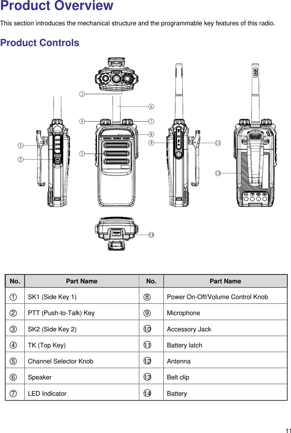
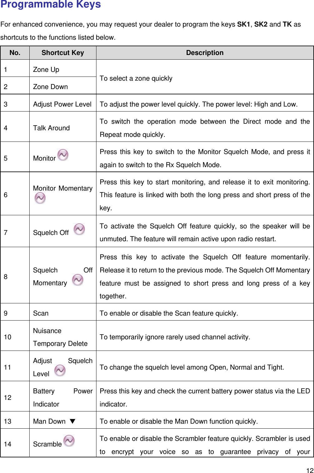
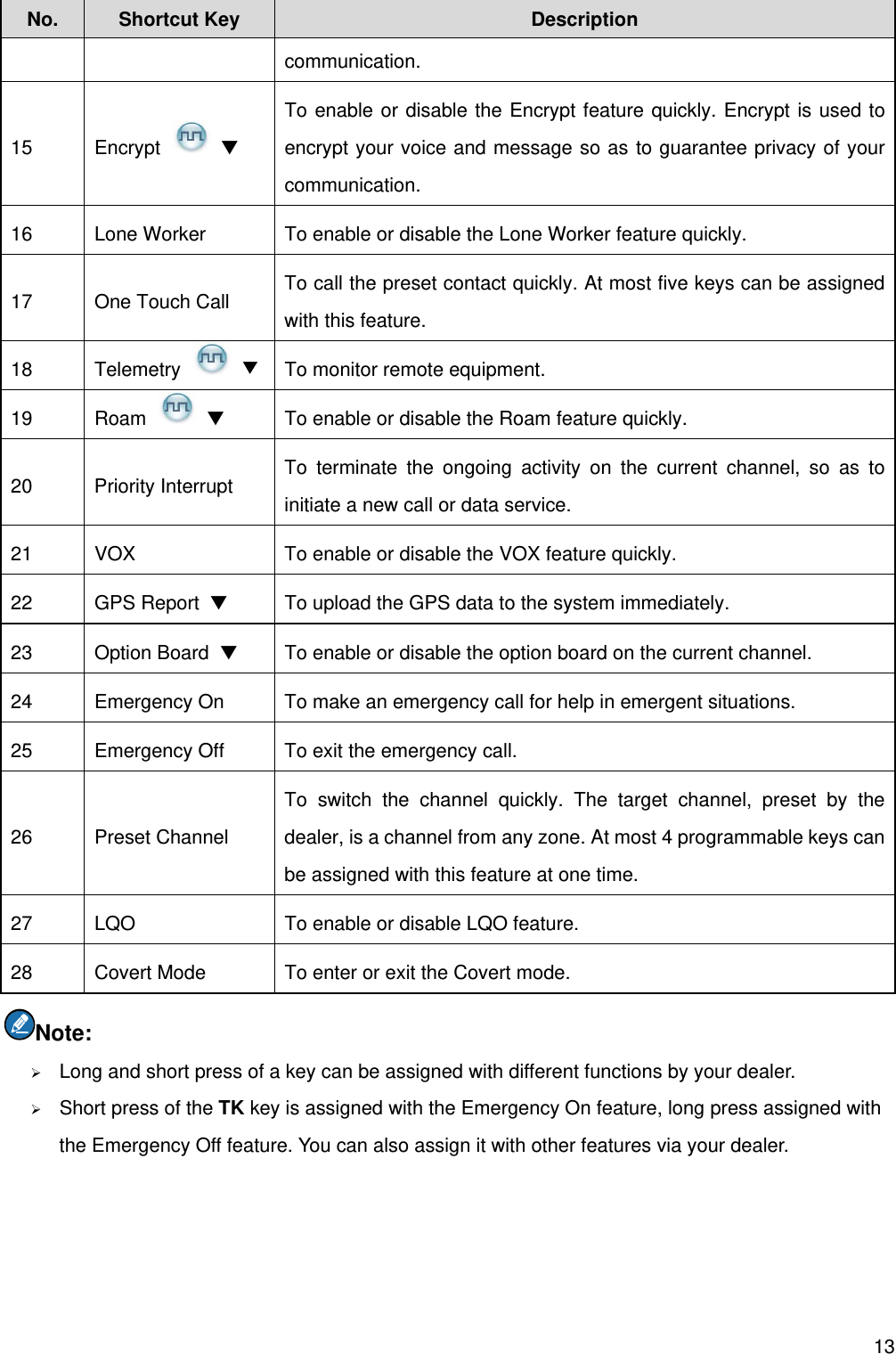
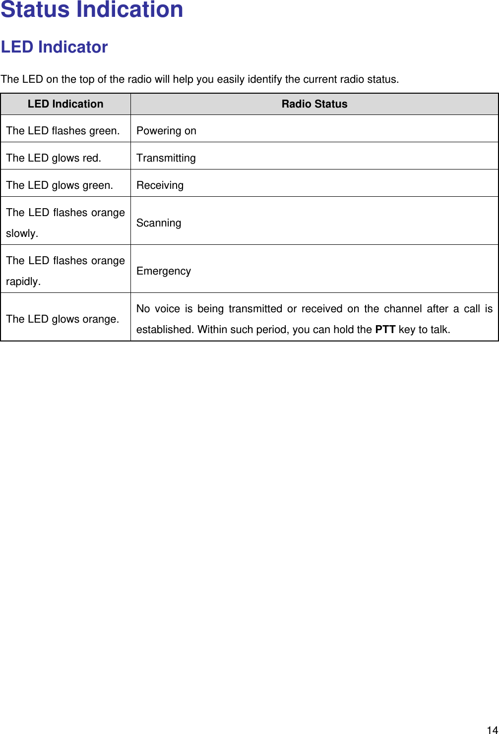
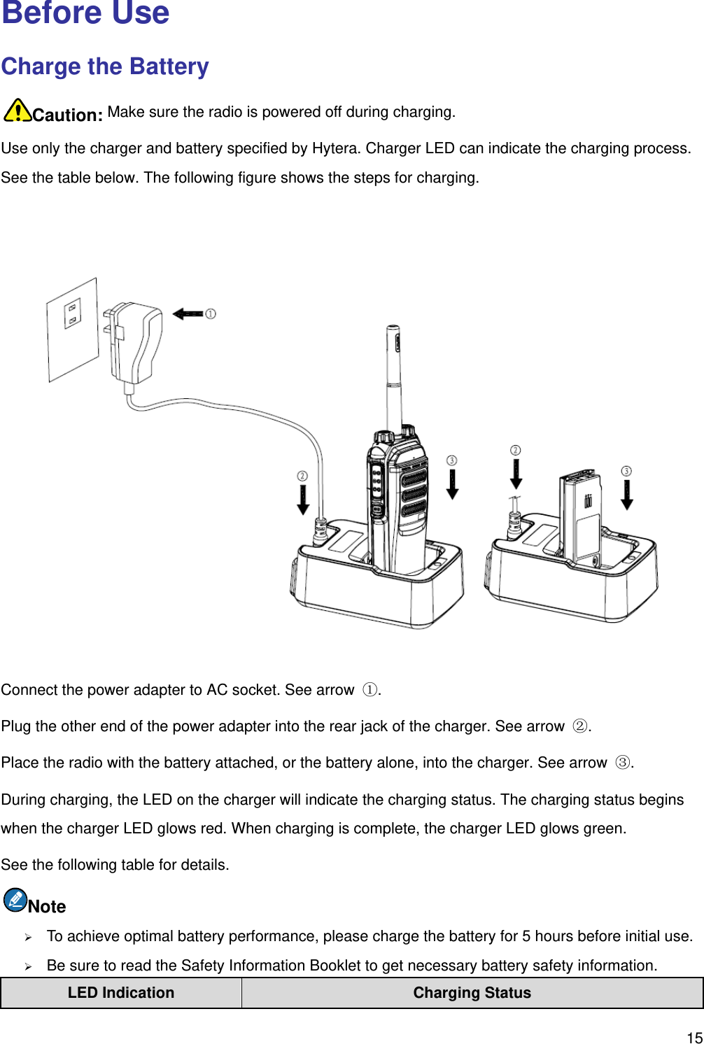
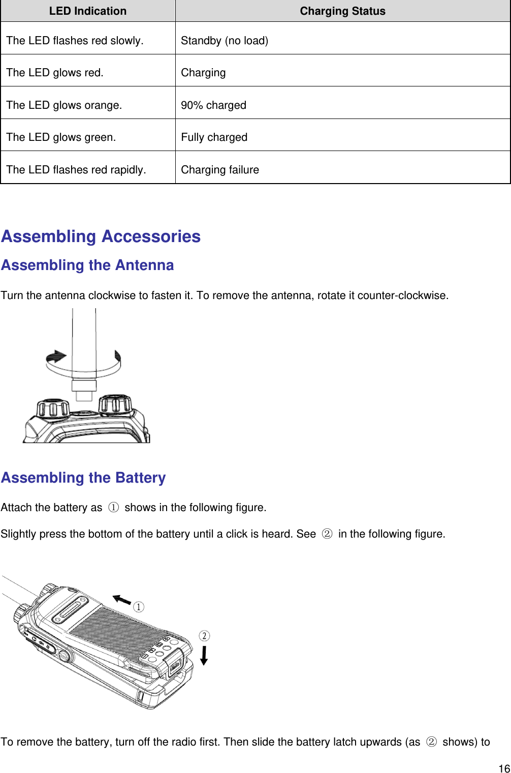
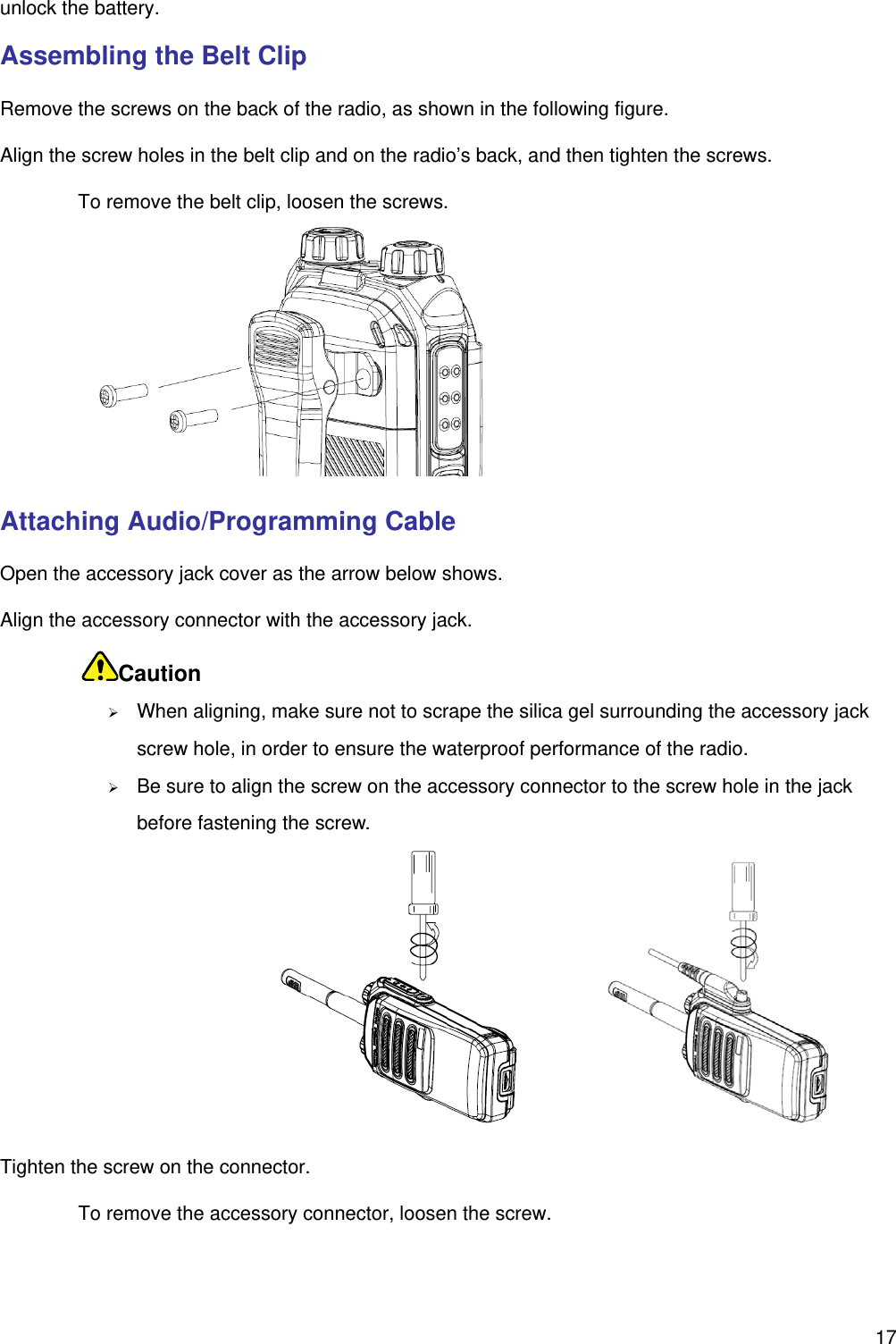
User Manual
Users Manual
Navigation menu
Upload a User Manual
Namespaces
Wiki Guide
HTML
PDF
Info
Views
User Manual
Discussion / Help
Navigation