Hytera Communications PD79XEX Ex Digital Radio User Manual
Hytera Communications Corporation Ltd. Ex Digital Radio
Contents
- 1. Users Manual
- 2. User Manual
User Manual

1
File No: HYT-I&M-71XEx-001
Rev: V1.0
Preface
Thanks for your favor in our product. To derive optimum performance from the product, please read this
manual and the supplied Safety Information Booklet carefully before use.
This manual is applicable to the following model:
PD71X(X may represent 2, 5, 6 or 8)Ex Digital Portable Radio
1
Copyright Information
Hytera is the trademark or registered trademark of Hytera Communications Co., Ltd. (the Company) in
PRC and/or other countries or areas. The Company retains the ownership of its trademarks and product
names. All other trademarks and/or product names that may be used in this manual are properties of
their respective owners.
The product describes in this manual may include the Company’s computer programs stored in memory
or other media. Laws in PRC and/or other countries or areas protect the exclusive rights of the Company
with respect to its computer programs. The purchase of this product shall not be deemed to grant, either
directly or by implication, any rights to the purchaser regarding the Company’s computer programs. Any
of the Company’s computer programs may not be copied, modified, distributed, decompiled, or
reverse-engineered in any manner without the prior written consent of the Company.
The AMBE+2TM voice coding technology embodied in this product is protected by intellectual property
rights including patent rights, copyrights and trade secrets of Digital Voice Systems, Inc. This voice
coding technology is licensed solely for use within this product. The user of this technology is explicitly
prohibited from attempting to decompile, reverse engineer, or disassemble the Object Code or in any
other way convert the Object Code into a human readable form.
U.S. Patent No: #6,912,495 B2, #6,199,037 B1, #5,870,405, #5,826,222, #5,754,974, #5,701,390,
#5,715,365, #5,649,050, #5,630,011, #5,581,656, #5,517,511, #5,491,772, #5,247,579, #5,226,084 and
#5,195,166.
Disclaimer
The Company endeavors to achieve the accuracy and completeness of this manual, but no warranty of
accuracy or reliability is given. All the specifications and designs are subject to change without notice
due to continuous technology development. No part of this manual may be copied, modified, translated,
or distributed in any manner without the express written permission of us.
We do not guarantee, for any particular purpose, the accuracy, validity, timeliness, legitimacy or
completeness of the Third Party products and contents involved in this manual.
If you have any suggestions or would like to learn more details, please visit our website at:
http://www.hytera.com.
RF Radiation Information
This product must be restricted to operations in an Occupational/Controlled RF exposure Environments.
Users must be fully aware of the hazards of the exposure and able to exercise control over their RF
exposure to qualify for the higher exposure limits.
RF Radiation Profile
Radio Frequency (RF) is a frequency of electromagnetic radiation in the range at which radio signals are
transmitted. RF technology is widely used in communication, medicine, food processing and other fields.
It may generate radiation during use.
RF Radiation Safety
In order to ensure user health, experts from relevant industries including science, engineering, medicine
and health work with international organizations to develop standards for safe exposure to RF radiation.
These standards consist of:
United States Federal Communications Commission, Code of Federal Regulations; 47CFR part 2
sub-part J;
American National Standards Institute (ANSI)/Institute of Electrical and Electronic Engineers (IEEE)
C95. 1-1992;
Institute of Electrical and Electronic Engineers (IEEE) C95.1-1999;
International Commission on Non-Ionizing Radiation Protection (ICNIRP) 1998.
FCC Regulations
Federal Communication Commission (FCC) requires that all radio communication products should meet
the requirements set forth in the above standards before they can be marketed in the U.S, and the
manufacturer shall post a RF label on the product to inform users of operational instructions, so as to
enhance their occupational health against exposure to RF energy.
Operational Instructions and Training Guidelines
To ensure optimal performance and compliance with the occupational/controlled environment RF energy
exposure limits in the above standards and guidelines, users should transmit not more than 50% of the
time and always adhere to the following procedures:
RF energy will be generated only when the radio is transmitting.
If you are not using a body-worn accessory and are not using the radio in the
intended use position in front of the face, then ensure the antenna and the radio
are kept at least 2.5 cm (one inch) from the body when transmitting. Keeping the
radio at the proper distance is important because RF exposures decrease with
increasing distance from the antenna.
FCC Statement
This equipment has been tested and found to comply with the limits for a Class B digital
device, pursuant to part 15 of FCC Rules. These limits are designed to provide
reasonable protection against harmful interference in a residential installation. This
equipment generates and can radiate radio frequency energy and, if not installed and
used in accordance with the instructions, may cause harmful interference to radio
communications. However, there is no guarantee that interference will not occur in a
particular installation. If this equipment does cause harmful interference to radio or
television reception, which can be determined by turning the equipment off and on, the
user is encouraged to try to correct.
The interference by one or more of the following measures:
● Reorient or relocate the receiving antenna. Increase the separation between the
equipment and receiver.
● Connect the equipment into an outlet on a circuit different from that to which the
receiver is connected.
● Consult the dealer or an experienced radio/TV technician for help
Operation is subject to the following two conditions: 1. This device may not cause harmful
interference, and 2. This device must accept any interference received, including
interference that may cause undesired operation.
Note:” Changes or modifications to this unit not expressly approved by the party
responsible for compliance could void the user’s authority to operate the equipment.”
Compliance with RF Exposure Standards
Hytera’s 2-way radio complies with the following RF energy exposure standards and
guidelines:
• United States Federal Communications Commission, Code of Federal Regulations; 47
CFR §§ 1.1307, 1.1310 and 2.1093
• American National Standards Institute (ANSI) / Institute of Electrical and Electronic
Engineers (IEEE) C95. 1-1992
• Institute of Electrical and Electronic Engineers (IEEE) C95.1-1999 Edition
RF Exposure Compliance and Control Guidelines and
Operating Instructions
To control your exposure and ensure compliance with the occupational/controlled
environment exposure limits always adhere to the following procedures.
Guidelines:
• Do not remove the RF Exposure Label from the device.
• User awareness instructions should accompany device when transferred to other users.
• Do not use this device if the operational requirements described herein are not met.
Operating Instructions:
• Transmit no more than the rated duty factor of 50% of the time. To transmit (talk), push
the Push-To-Talk (PTT) button. To receive calls, release the PTT button. Transmitting
50 % of the time, or less, is important because this radio generates measurable RF
energy exposure only when transmitting (in terms of measuring for standards
compliance).
• Hold the radio in a vertical position in front of face with the microphone (and the other
parts of the radio, including the antenna) at least one inch (2.5 cm) away from the nose.
Keeping the radio at the proper distance is important because RF exposures decrease
with distance from the antenna. Antenna should be kept away from eyes.
• When worn on the body, always place the radio in a Hytera’s approved clip, holder,
holster, case, or body harness for this product. Using approved body-worn accessories is
important because the use of Hytera’s or other manufacturer’s non-approved accessories
may result in exposure levels, which exceed the FCC’s occupational/controlled
environment RF exposure limits.
• If you are not using a body-worn accessory and are not using the radio in the intended
use position in front of the face, then ensure the antenna and the radio are kept at least
2.5 cm (one inch) from the body when transmitting. Keeping the radio at the proper
distance is important because RF exposures decrease with increasing distance from the
antenna.
• Use only manufacturer’s name approved supplied or replacement antennas, batteries,
and accessories. Use of non-manufacturer-name approved antennas, batteries, and
accessories may exceed the FCC RF exposure guidelines.
•For a list of Hytera’s approved accessories (see the user manual), or (visit the following
website which lists approved accessories: http: add website address), or(The
manufacturer should include the appropriate bracketed item{s} in the manual.)
• For a list of Hytera’s approved accessories (see the user manual), or (visit the following
website which lists approved accessories: www.hytera.cn
IC statement
The device has been tested and compliance with SAR limits, users can obtain Canadian
information on RF exposure and compliance
Après examen de ce matériel aux conformité aux limites DAS et/ou aux limites d’intensité
de champ RF, les utilisateurs peuvent sur l’exposition aux radiofréquences et la
conformité and compliance d’acquérir les informations correspondantes

EU Regulatory Conformance
As certified by the qualified laboratory, the product is in compliance with the essential
requirements and other relevant provisions of the Directive 1999/5/EC. Please note
that the above information is applicable to EU countries only.

3
Contents
1. Documentation Conventions ............................................................................................................. 6
1.1 Instructional Icons ........................................................................................................................... 6
1.2 Notational Conventions ................................................................................................................... 6
1.3 Key Operation ................................................................................................................................. 6
2. Intrinsically Safe Radio Information ................................................................................................. 8
2.1 Equipment marking ......................................................................................................................... 8
2.2 No Misoperations ............................................................................................................................ 8
2.3 Safety Instructions .......................................................................................................................... 9
2.4 Specifications ................................................................................................................................ 10
2.5 Compliance Standards .................................................................................................................. 10
3. Items in the Package ........................................................................................................................ 12
4. Product Overview ............................................................................................................................. 13
4.1 Product Controls ........................................................................................................................... 13
4.2 Programmable Keys ..................................................................................................................... 14
5. Status Indication .............................................................................................................................. 16
5.1 LED Indicator ................................................................................................................................ 16
6. Before Use ........................................................................................................................................ 17
6.1 Charge the Battery ........................................................................................................................ 17
6.2 Assembling Accessories ............................................................................................................... 18
6.2.1 Assembling the Antenna ..................................................................................................... 18
6.2.2 Assembling the Battery ....................................................................................................... 18
6.2.3 Assembling the Belt Clip ..................................................................................................... 19
6.2.4 Attaching Audio/Programming Cable .................................................................................. 19
7. Basic Operations .............................................................................................................................. 21
7.1 Powering On/Off ........................................................................................................................... 21
7.2 Adjusting the Volume .................................................................................................................... 21
7.3 Adjust Power Level ....................................................................................................................... 21
7.4 Selecting a Zone ........................................................................................................................... 21
7.5 Selecting a Channel ...................................................................................................................... 21
7.6 Switching the Channel Mode ........................................................................................................ 21
8. Call ..................................................................................................................................................... 23
8.1 Private Call ........................................................................................................................... 23
8.2 Group Call ............................................................................................................................ 23
8.3 All Call .................................................................................................................................. 23
8.4 Calls on Analog Channels ..................................................................................................... 23
8.5 One Touch Call ............................................................................................................................. 24

4
8.6 Time-out Timer (TOT) ................................................................................................................... 24
8.7 Busy Channel Lockout .................................................................................................................. 24
8.8 Pseudo Trunking .................................................................................................................. 24
9. Functions and Operations ............................................................................................................... 25
9.1 Rent .............................................................................................................................................. 25
9.2 Scan .............................................................................................................................................. 25
9.3 Roam ▼ .............................................................................................................................. 25
9.4 Talk Around .................................................................................................................................. 26
9.5 Monitor .................................................................................................................................... 26
9.6 Squelch Off ........................................................................................................................... 26
9.7 Adjust Squelch Level ............................................................................................................. 26
9.8 VOX .............................................................................................................................................. 27
9.9 LQO .............................................................................................................................................. 27
9.10 Covert Mode ............................................................................................................................... 27
9.11 GPS Report ▼ .................................................................................................................. 27
9.12 Battery Power Indicator ............................................................................................................... 27
9.13 Audio Feedback Suppression ..................................................................................................... 28
9.14 MIC AGC .................................................................................................................................... 28
9.15 Radio Registration Service ................................................................................................. 28
9.16 Telemetry ▼ ...................................................................................................................... 28
9.17 Man Down ▼ ............................................................................................................................. 29
9.18 Lone Worker ............................................................................................................................... 29
9.19 Priority Interrupt .......................................................................................................................... 29
9.19.1 Manual Priority Interrupt ................................................................................................... 29
9.19.2 Auto Priority Interrupt ........................................................................................................ 30
9.20 Scrambler /Encrypt .......................................................................................................... 30
9.21 Emergency Alarm ....................................................................................................................... 31
9.21.1 Emergency Type ............................................................................................................... 31
9.21.2 Emergency ID Type ................................................................................................... 31
9.21.3 Emergency Mode .............................................................................................................. 32
9.21.4 Operation Methods for Analog Emergency ............................................................... 32
9.21.5 Operation Method for Digital Emergency ................................................................. 34
10. Troubleshooting ............................................................................................................................. 36
11. Care and Cleaning .......................................................................................................................... 38
5
12. Appendix ......................................................................................................................................... 39
12.1 Signaling Introduction ................................................................................................................. 39
12.1.1 HDC1200 .......................................................................................................................... 39
12.1.2 5-Tone ............................................................................................................................... 39
12.1.3 2-Tone ............................................................................................................................... 40
6
1. Documentation Conventions
For your better understanding of this manual, please read the following conventions first.
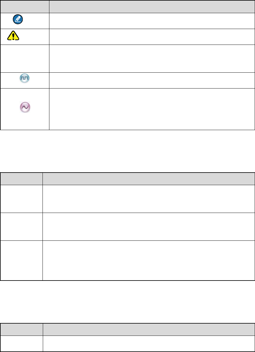
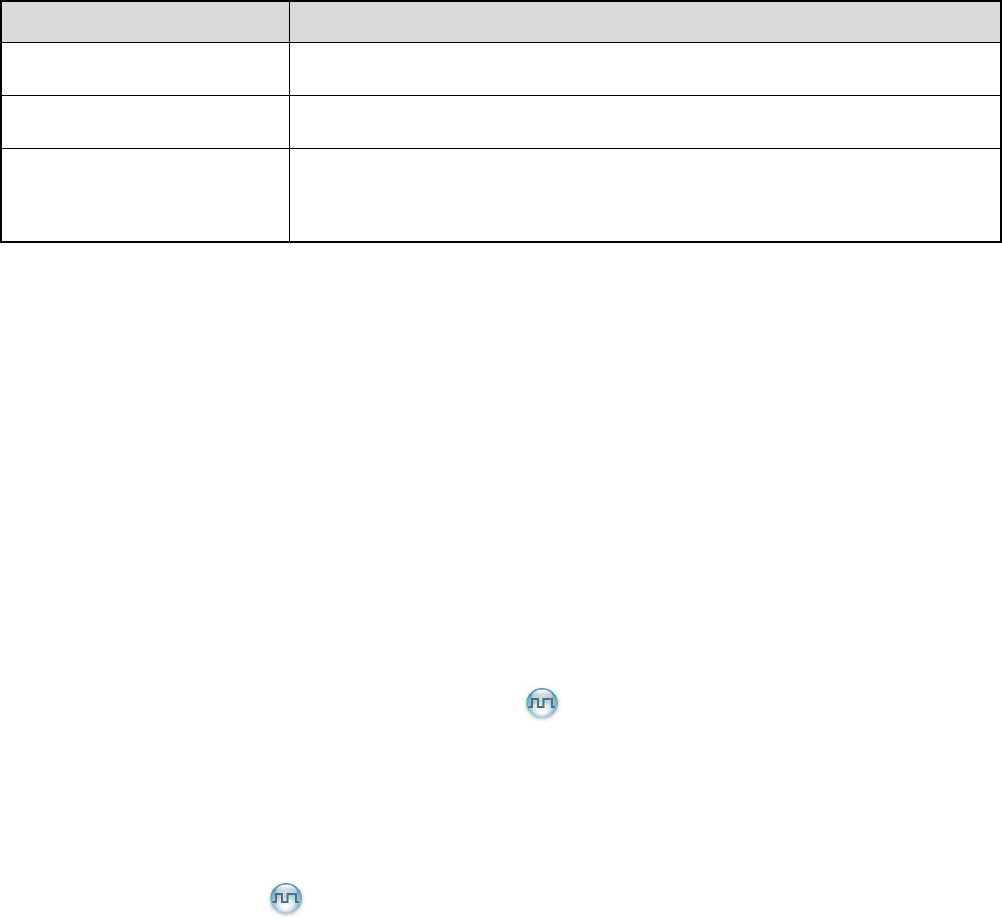
1.1 Instructional Icons
Icon Description
Note Indicates references that can further describe the related topics.
Caution Indicates situations that could cause data loss or equipment damage.
▼
Indicates that the function is unavailable on PD71XEx LT digital portable
radio.
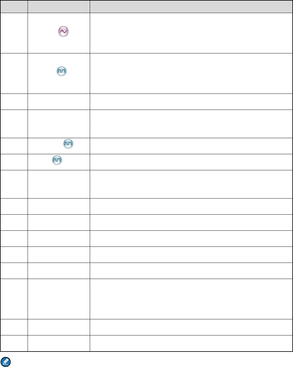
Indicates functions that are available on digital channel only.
Indicates functions that are available on analog channel only.
Functions marked with no function icons are available on both analog
and digital channels.
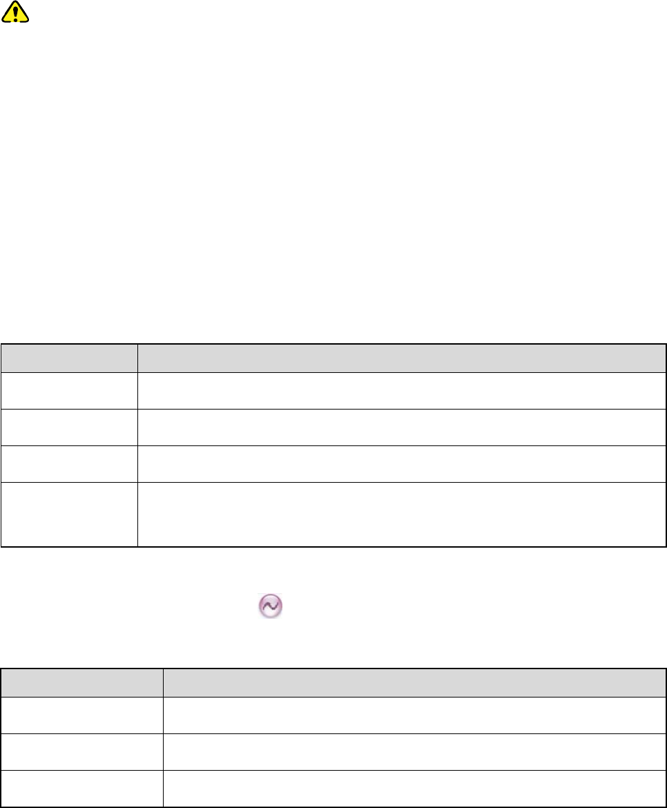
1.2 Notational Conventions
Convention Description
“ ”
The quotation marks enclose the name of a software interface element.
For example, click “OK”.
Bold The text in boldface denotes the name of a hardware button. For example,
press the PTT key.
->
The symbol directs you to access a multi-level menu. For example, to
select “New” from the “File” menu, we will describe it as follows: File ->
New.
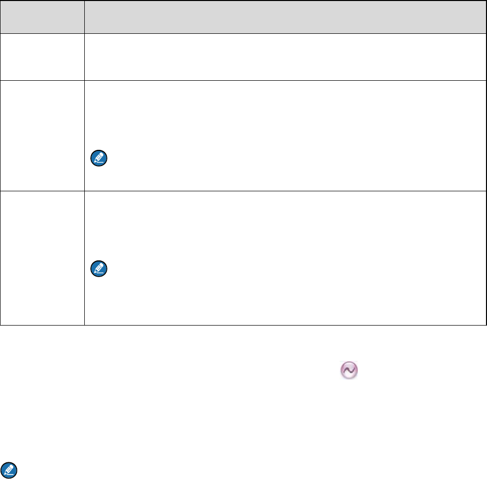
1.3 Key Operation
Operation Definition
Short press To press a key and release it quickly.

7
Operation Definition
Long press To press a key for the preset time (2s by default) and release it.
Hold To press a key and do not release it.
8
2. Intrinsically Safe Radio Information
2.1 Equipment marking
FM/CAN
z Class I, Zone 1 AEx/Ex ib IIC T4 Gb
z Class II, III Div 1, Group E, F, G T120℃
ATEX
z II 2G Ex ib IIC T4
z II 2D Ex ib IIIC T120℃ IP5X
z I M2 Ex ib
IECEx
z Ex ib IIC T4
z Ex ib IIIC T120℃ IP5X
z Ex ib I
Certificate Number
z FM13ATEX0023X
z FMG 13.0010X
2.2 No Misoperations
Stop operating this product and leave the explosive atmosphere immediately when the safety or integrity
of the product is endangered, and deliver it to your local dealer for examination.
These items may endanger the product’s safety or integrity:
z The radio is stored improperly;
z The radio is faulty;
z The radio works with overload;
z The radio’s operational error or threshold value is out of allowed range.
z The radio is damaged during transportation;
z The radio’s housing is obviously damaged or cracked;
z The radio logo or model is hard to be recognized;

9
2.3 Safety Instructions
Caution
To protect you against any property loss, bodily injury or even death, be sure to observe the following
safety instructions:
z Use only the Ex-battery BL1807-Ex specified by the Company. The use of other batteries may
result in Ex-protection (intrinsic safety) failure.
z Charge the battery in a non-hazardous area only with the designated charger.
z Do not remove the battery from the radio in a hazardous area.
z Do not carry any standby battery into a hazardous area.
z Use the accessories specified by the Company only. Do not replace the accessories in a
hazardous area.
z Do not use a damaged antenna. If a damaged antenna comes into contact with your skin, a minor
burn may result.
z Do not expose the radio to direct sunlight for a long time, nor place it close to a heating source.
z Hold the radio upright and keep its microphone 2.5 to 5 centimeters away from your mouth during
use.
z If you wear a radio on your body, ensure its antenna is at least 2.5 centimeters away from your
body during transmission.
z Do not carry the radio into Zone 0 and 20. Please do not use the radio out of the operating
temperature range specification of this product.
z Do not attempt to repair and service the radio, batteries and its accessories. Please contact your
dealer for repair and servicing.
z Do not dissemble or redo the radio. Unauthorized modification of the radio may result in
termination of Ex-protection (intrinsic safety) of the radio.
z Improper usage of the product other than it is intended to be used for will impair safety of the
product, yourself and surrounding environment.

10
2.4 Specifications
Item Specifications
Rated Operating Voltage DC 7.4V
Max. Operating Voltage DC 8.4V
Max. Operating Current 1.5A
Weight (with standard antenna
& battery) About 498g
Sensitivity 0.3μV
RF Power Output 1W
Rated Audio Power Output 0.5W
Audio Distortion 3%
Ambient Temperature -20℃ to +50℃
Storage Temperature -30℃ to +60℃
Charging Temperature 0℃ to +40℃
Battery Ex-battery BL1807-Ex (1800mAh)
Battery Life About 14 hours (5-5-90 duty cycle)
Charging Time About 4 hours
2.5 Compliance Standards
Standard Issue Date
FM
FM Class 3600 2011
FM Class 3611 2004
FM Class 3810 2005
ANSI/IEC-60529(Ed. 4.0) 2004
ANSI/ISA-60079-0(12.00.01) 2009

11
Standard Issue Date
ANSI/ISA-60079-11(12.02.01) 2012
ANSI/ISA-60079-31(12.10.03) 2009
ANSI/ISA-61010-1(82.02.01) 2004
CAN
CAN/CSA-C22.2 No.0-M91 2006
CAN/CSA-C22.2 No.142-M1987 2009
CAN/CSA-C22.2 No.213-M1987 2008
CAN/CSA-C22.2 No.60079-0 (Ed. 5.0) 2011
CAN/CSA-C22.2 No.60079-11 (Ed. 5.0) 2011
CAN/CSA-C22.2 No.60079-31 (Ed.1.0) 2012
CAN/CSA-C22.2 No.60529 (Ed. 5.0) 2005
CAN/CSA-C22.2 No.61010-1 (Ed. 2.0) 2009
ATEX
EN 60079-0 (Ed. 5.0) 2009
EN 60079-11 (Ed. 6.0) 2012
EN 60079-31 (Ed. 1.0) 2009
EN 60529+A1 (Ed. 2.0) 1992
IECEx
IEC-60079-0 (Ed. 6.0) 2011
IEC-60079-11 (Ed. 6.0) 2011
IEC-60079-31 (Ed. 1.0) 2008
12
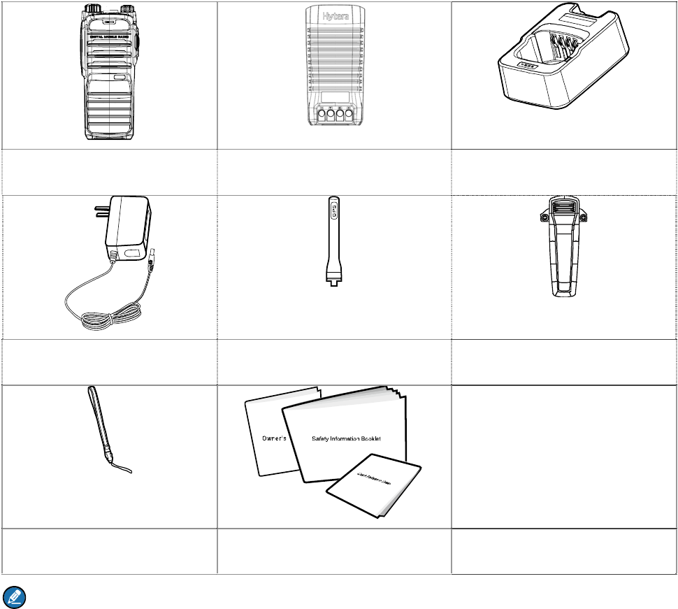
3. Items in the Package
Please unpack carefully and check that all items listed below are received. If any item is missing or
damaged, please contact your dealer.
Radio Battery Charger
Power Adapter Antenna Belt clip
Strap Documentation Kit
Note: The frequency band of the antenna is marked on the label of the antenna; if not, refer to the
label on the radio for frequency band information.
13
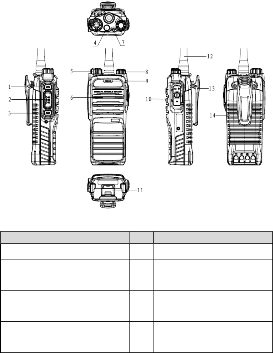
4. Product Overview
This section introduces the mechanical structure and the programmable key features of this radio.
4.1 Product Controls
No. Part Name No. Part Name
○
1 SK1 (Side Key 1) ○
8 Power On-Off/Volume Control Knob
○
2 PTT (Push-to-Talk) Key ○
9 Microphone
○
3 SK2 (Side Key 2) ○
10 Accessory Jack
○
4 TK (Top Key) ○
11 Battery latch
○
5 Channel Selector Knob ○
12 Antenna
○
6 Speaker ○
13 Belt clip
○
7 LED Indicator ○
14 Battery
14
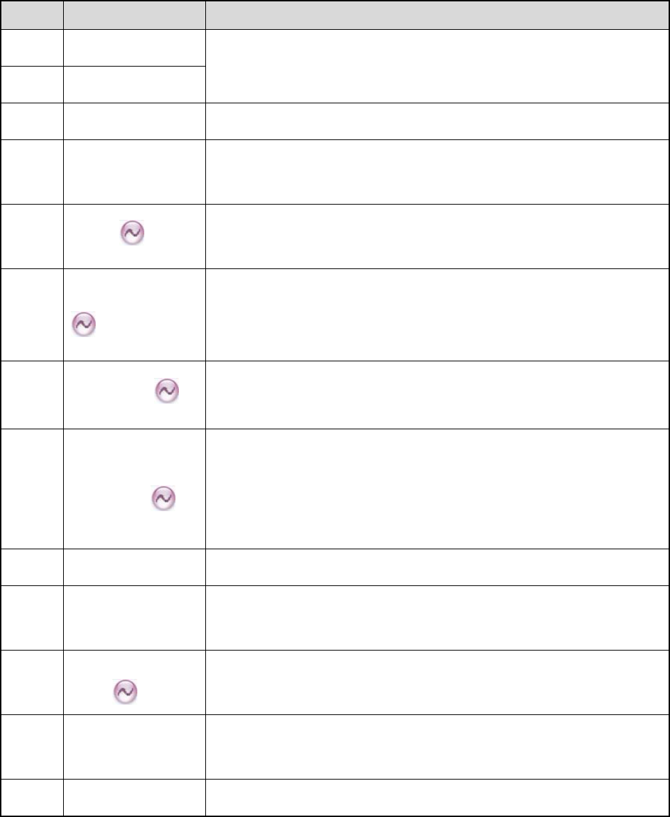
4.2 Programmable Keys
For enhanced convenience, you may request your dealer to program the keys SK1, SK2 and TK as
shortcuts to the functions listed below.
No. Shortcut Key Description
1 Zone Up
To select a zone quickly
2 Zone Down
3 Adjust Power Level To adjust the power level quickly. The power level: High and Low.
4 Talk Around
To switch the operation mode between the Direct mode and the
Repeat mode quickly.
5 Monitor
Press this key to switch to the Monitor Squelch Mode, and press it
again to switch to the Rx Squelch Mode.
6
Monitor Momentary
Press this key to start monitoring, and release it to exit monitoring.
This feature is linked with both the long press and short press of the
key.
7 Squelch Off
To activate the Squelch Off feature quickly, so the speaker will be
unmuted. The feature will remain active upon radio restart.
8
Squelch Off
Momentary
Press this key to activate the Squelch Off feature momentarily.
Release it to return to the previous mode. The Squelch Off Momentary
feature must be assigned to short press and long press of a key
together.
9 Scan To enable or disable the Scan feature quickly.
10
Nuisance
Temporary Delete
To temporarily ignore rarely used channel activity.
11
Adjust Squelch
Level
To change the squelch level among Open, Normal and Tight.
12
Battery Power
Indicator
Press this key and check the current battery power status via the LED
indicator.
13 Man Down ▼ To enable or disable the Man Down function quickly.
15
No. Shortcut Key Description
14 Scramble
To enable or disable the Scrambler feature quickly. Scrambler is used
to encrypt your voice so as to guarantee privacy of your
communication.
15 Encrypt ▼
To enable or disable the Encrypt feature quickly. Encrypt is used to
encrypt your voice and message so as to guarantee privacy of your
communication.
16 Lone Worker To enable or disable the Lone Worker feature quickly.
17 One Touch Call
To call the preset contact quickly. At most five keys can be assigned
with this feature.
18 Telemetry ▼ To monitor remote equipment.
19 Roam ▼ To enable or disable the Roam feature quickly.
20 Priority Interrupt
To terminate the ongoing activity on the current channel, so as to
initiate a new call or data service.
21 VOX To enable or disable the VOX feature quickly.
22 GPS Report ▼ To upload the GPS data to the system immediately.
23 Option Board ▼ To enable or disable the option board on the current channel.
24 Emergency On To make an emergency call for help in emergent situations.
25 Emergency Off To exit the emergency call.
26 Preset Channel
To switch the channel quickly. The target channel, preset by the
dealer, is a channel from any zone. At most 4 programmable keys can
be assigned with this feature at one time.
27 LQO To enable or disable LQO feature.
28 Covert Mode To enter or exit the Covert mode.
Note:
¾ Long and short press of a key can be assigned with different functions by your dealer.
¾ Short press of the TK key is assigned with the Emergency On feature, long press assigned with
the Emergency Off feature. You can also assign it with other features via your dealer.

16
5. Status Indication
5.1 LED Indicator
The LED on the top of the radio will help you easily identify the current radio status.
LED Indication Radio Status
The LED flashes green. Powering on
The LED glows red. Transmitting
The LED glows green. Receiving
The LED flashes orange
slowly.
Scanning
The LED flashes orange
rapidly.
Emergency
The LED glows orange.
No voice is being transmitted or received on the channel after a call is
established. Within such period, you can hold the PTT key to talk.
17
6. Before Use
6.1 Charge the Battery
Caution: Make sure the radio is powered off during charging.
Use only the charger and battery specified by Hytera. Charger LED can indicate the charging process.
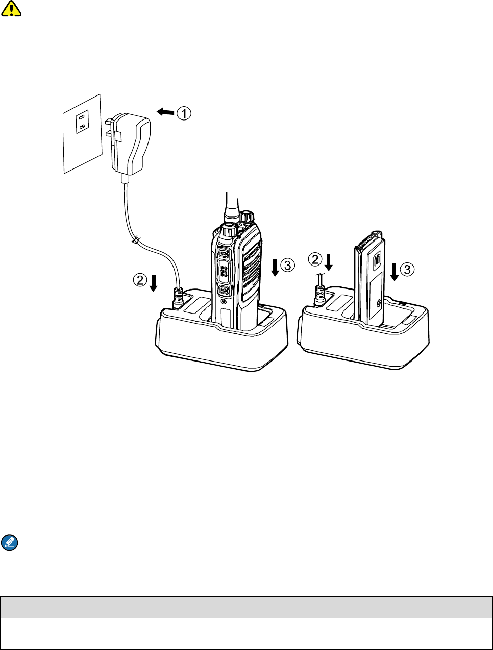
See the table below. The following figure shows the steps for charging.
Step 1 Connect the power adapter to AC socket. See arrow ①.
Step 2 Plug the other end of the power adapter into the rear jack of the charger. See arrow ②.
Step 3 Place the radio with the battery attached, or the battery alone, into the charger. See arrow ③.
During charging, the LED on the charger will indicate the charging status. The charging status begins
when the charger LED glows red. When charging is complete, the charger LED glows green.
See the following table for details.
Note
¾ To achieve optimal battery performance, please charge the battery for 5 hours before initial use.
¾ Be sure to read the Safety Information Booklet to get necessary battery safety information.
LED Indication Charging Status
The LED flashes red slowly. Standby (no load)
18
LED Indication Charging Status
The LED glows red. Charging
The LED glows orange. 90% charged
The LED glows green. Fully charged
The LED flashes red rapidly. Charging failure
6.2 Assembling Accessories
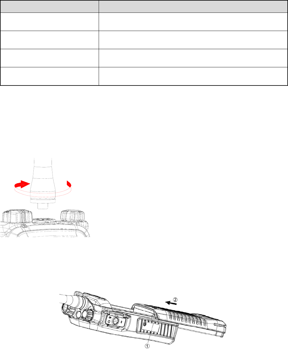
6.2.1 Assembling the Antenna
Turn the antenna clockwise to fasten it. To remove the antenna, rotate it counter-clockwise.
6.2.2 Assembling the Battery
Step 1 Align the battery slots with the guide rails on the radio, and push the battery ②.
Step 2 Open the battery latch and hold it down until the metal lock goes into the battery housing
completely.
19
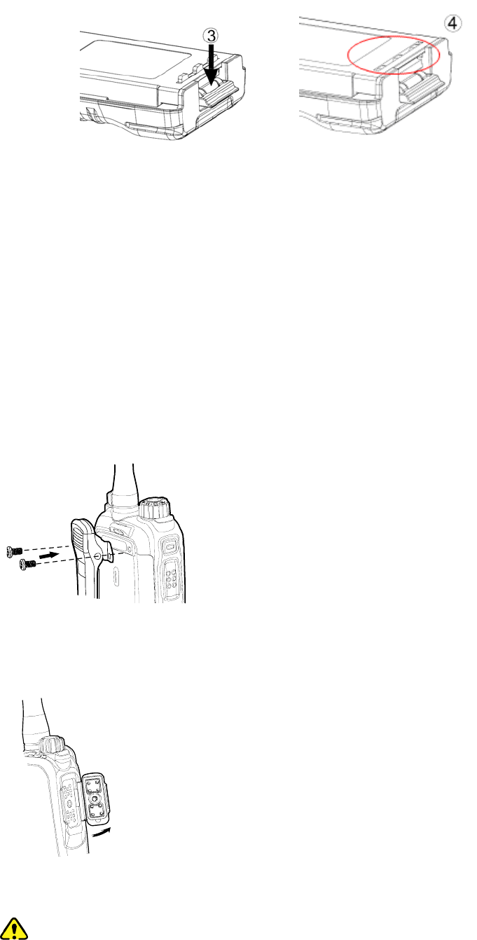
Step 3 Push the battery until it is fully fitted into the slot, and then release the battery latch.
To remove the battery, please power off the radio first. Then open the battery latch, and slide the battery
out while holding down the battery latch.
6.2.3 Assembling the Belt Clip
Step 1 Remove the screws on the back of the radio, as shown in the following figure.
Step 2 Align the screw holes in the belt clip and on the radio’s back, and then tighten the screws.
To remove the belt clip, loosen the screws.
6.2.4 Attaching Audio/Programming Cable
Step 1 Open the accessory jack cover as the arrow below shows.
Step 2 Align the accessory connector with the accessory jack.
Caution
¾ When aligning, make sure not to scrape the silica gel surrounding the accessory jack
screw hole, in order to ensure the waterproof performance of the radio.
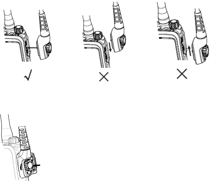
20
¾ Be sure to align the screw on the accessory connector to the screw hole in the jack
before fastening the screw.
Step 3 Tighten the screw on the connector.
To remove the accessory connector, loosen the screw.
21
7. Basic Operations
7.1 Powering On/Off
Rotate the Power On-Off/Volume Control knob clockwise/counter-clockwise until a click is heard to
turn the radio on/off.
7.2 Adjusting the Volume
After turning the radio on, rotate the Power On-Off/Volume Control knob clockwise to increase the
output sound volume, or counter-clockwise to decrease it.
7.3 Adjust Power Level
With this feature, you may switch power levels quickly. Generally, we recommend you to adopt low
power for battery saving. However, if you cannot communicate with radios located at a distant place with
low power, please select high power.
Operation: Press the programmed Adjust Power Level key to switch the Tx power of the current
channel between High and Low.
7.4 Selecting a Zone
A zone is a group of channels exhibiting the same property. You can list such channels into a zone for
convenient management to them. This radio supports 3 zones: Zone 1, Zone 2 and Zone 3, each of
which can contain 16 channels at most.
You may quickly toggle to your wanted zone by pressing the programmed Zone Up or Zone Down key.
When toggling to a zone, you will hear the alert tone for the zone (one alert tone for Zone 1, two alert
tones for Zone 2 and three alert tones for Zone 3).
7.5 Selecting a Channel
After turning the radio on, rotate the Channel Selector knob to select a needed channel. You can also
switch to the designated channel by pressing the programmed Preset Channel key.
If the Channel Notify function is active, you will hear the corresponding channel number when switching
to any channel.
7.6 Switching the Channel Mode
Each channel can be programmed as either analog channel or digital channel via your dealer. If the
22
current zone includes both analog and digital channels, you may quickly switch between digital and
analog channels through the Channel Selector knob.

23
8. Call
To ensure optimal volume of the transmitted voice, keep the microphone approximately 2.5 to 5
centimeters away from your mouth.
8.1 Private Call
Initiating a Call
In the home screen, hold the PTT key to transmit a private call to the private call contact preset for the
current channel.
Note: Your dealer may preset a contact for each digital channel. The preset contact could be a
private call contact, a group call contact or an all call contact.
Receiving a Call or Calling Back
When a private call is received, you can listen to it without any operation. You may hold the PTT key
within the preset time period to call back.
8.2 Group Call
Initiating a Call
In the home screen, hold the PTT key to transmit a group call to the group call contact preset for the
current channel.
Receiving a Call or Calling Back
When a group call is received, you can listen to it without any operation, and you may hold the PTT key
within the preset time period to call back.
8.3 All Call
In the home screen, hold the PTT key to transmit an all call to the all call contact preset for the current
channel. When an all call is received, you can listen to it without any operation.
Note: You can transmit an all call only when the feature is enabled by your dealer. However, you
cannot call back an all call.
8.4 Calls on Analog Channels
To transmit a call on the analog channel, hold the PTT key and speak into the microphone. To receive,
release the PTT key.

24
8.5 One Touch Call
You may request your dealer to set the One Touch Call key for you. The One Touch Call feature is used
to make a call quickly. The call contact and call type are preset by the dealer.
Operation: Press the programmed One Touch Call key to initiate a call.
8.6 Time-out Timer (TOT)
TOT aims to prevent any user from occupying a channel for an extended period. If the preset time
expires, the radio will automatically terminate the transmission and keep beeping. To stop beeping,
please release the PTT key. You must wait for a certain time period (preset by your dealer) to initiate
another transmission.
Note: This feature is null in Emergency mode.
8.7 Busy Channel Lockout
If enabled (via the programming software), this feature can prevent your radio interfering with other
transmitting radios on the same channel. If you hold the PTT key while the channel is in use, your radio
will keep beeping, alerting you to transmission prohibition. When the channel is free, you can hold the
PTT key to transmit.
8.8 Pseudo Trunking
This feature can be enabled via the programming software. If the radio operates on a channel with this
feature enabled and a time slot is already occupied, the radio can transmit and receive in another free
slot.

25
9. Functions and Operations
9.1 Rent
You can rent the radio from your dealer. When the rental period expires, you are not allowed to use this
radio.
If you rent this radio, please obtain the rental time information from your dealer. If the Rent Pre-Alert
feature is enabled, the radio will give a tone periodically to remind you the remaining time of your rental.
9.2 Scan
With the Scan feature, you can listen to communication activities on other channels so that you can keep
a close track of your team members.
Operation:
Step 1 To enable the feature, press the programmed Scan key in standby mode (a high-pitched tone
sounds); or switch to a channel for which the Auto Scan feature is enabled. When you switch to
the channel, the radio will start scan automatically.
Step 2 After the feature is enabled, the radio will scan according to the scan list set for the channel.
The scanning process is as follows:
z During scanning, the LED flashes orange.
z When activities are detected on a channel, the radio will stay on the channel to receive
current activities, and the LED will glow green.
¾ If you don’t want to hear the activities on the channel, press the programmed Nuisance
Temporary Delete key to remove the channel from the scan list temporarily.
¾ If you want to continue listening to the activities on the channel, press the programmed
Monitor key or Squelch Off key during scan stay.
¾ To exit the scanning process, press the programmed Scan key again (a low-pitched tone
sounds).
9.3 Roam ▼
This feature allows the radio to communicate between sites in the same IP Multi-site Connect system.
After the feature enabled, the radio can communicate via any site in the IP Multi-site Connect system,
thus ensuring seamless communication in the system.
Operation: You can enable or disable the Roam feature by pressing the programmed Roam key.

26
9.4 Talk Around
You can continue to communicate in DM mode by pressing the programmed Talk Around key when
your repeater malfunctions, or when your radio and the communicating radio are out of the repeater’s
range but within talking range of each other.
Operation: Press the programmed Talk Around key to enable the feature (a high-pitched tone sounds).
To disable the feature, press this key again (a low-pitched tone sounds).
9.5 Monitor
To adjust match conditions for signal receiving, you can enable the Monitor feature.
Operation:
z Press the programmed Monitor key to enable the feature (a high-pitched tone sounds). To disable
the feature, press this key again (a low-pitched tone sounds).
z Hold down the programmed Monitor Momentary key to enable the feature (a high-pitched tone
sounds). To disable the feature, release this key (a low-pitched tone sounds).
9.6 Squelch Off
If the Squelch Off feature is activated, the speaker will keep unmuted no matter whether the signals are
present.
Operation:
z Press the programmed Squelch Off key to enable the feature (a high-pitched tone sounds). Then the
radio sounds background noise. Press the key again to disable the feature (a low-pitched tone
sounds).
z Press the programmed Squelch Off Momentary key to enable the feature (a high-pitched tone
sounds). Then the radio sounds background noise. Press the key again to disable the feature (a
low-pitched tone sounds).
9.7 Adjust Squelch Level
This feature allows you to adjust the squelch threshold required for the radio to be unmuted.
Generally, the higher squelch level requires stronger signal for the radio to be unmuted. If the squelch
level is set to “Open”, the speaker will keep unmuted irrespective of the satisfaction of decoding
conditions.
Operation: Press the programmed Adjust Squelch Level key to switch among Tight, Open and Normal
(when you switch from Tight to Open, a low-pitched tone and the background noise will sound).

27
z When you switch from Open to Normal, a high-pitched tone will sound and the background noise will
disappear.
z When you switch from Normal to Tight, a high-pitched tone will sound.
9.8 VOX
VOX indicates that you can trigger the voice transmission by speaking directly without holding the PTT
key. When the voice detected by the microphone reaches the volume to trigger the transmission, it will
be transmitted automatically.
Operation: You can enable or disable this feature by pressing the programmed VOX key.
9.9 LQO
This feature enables the radio to adjust the received voice volume automatically to fit different using
environments, as well as making the heard voice clear.
Operation: You can enable or disable the LQO feature by pressing the programmed LQO key.
9.10 Covert Mode
When this feature is enabled, the radio will disable any visible indications on it, such as the LED, , etc,
set by your dealer. This feature is mainly used in special missions.
Operation: Press the programmed Covert Mode key to enable or disable the Covert mode.
9.11 GPS Report ▼
With the GPS feature enabled, the radio will upload its positioning information to the system when the
system requires GPS information. The uploading method is set by the dealer.
Operation: Press the programmed GPS Report key to upload the GPS information quickly.
9.12 Battery Power Indicator
This feature allows you to know the current battery power.
Operation: Hold the programmed Battery Power Indicator key, and the radio will give an appropriate
LED indication to represent the current battery power. Release this key to stop the indication.
LED Indicator Battery Power
The LED glows green. High
28
LED Indicator Battery Power
The LED glows orange. Medium
The LED glows red. Low
The LED glows red and the
low battery tone sounds.
The power is under the low battery threshold. Now you need to charge it or
replace it to ensure the proper operation of the radio.
9.13 Audio Feedback Suppression
This feature is enabled by your dealer via the programming software. The enabled feature will weaken
the noise made by short-distance communication, so as to improve the voice quality.
9.14 MIC AGC
This feature is enabled by your dealer via the programming software. When it is enabled, the radio will
control the audio gain to a proper range during transmission, providing improved voice with proper
volume for the receiving radio.
9.15 Radio Registration Service
This feature is enabled by your dealer via the programming software. The radio will automatically
register in the system within a certain period after power-on. Then it can acquire online information of
other radios via accessing specific servers within the valid registration period.
9.16 Telemetry ▼
This feature allows you to remotely supervise the device connected with the radio. With this feature, you
can control the device and view its status at any time in case that you are away from the device.
The method for supervising the device is programmable by your dealer. The available methods are:
z To supervise the device via the radio
If a device is connected with the radio, you can use another radio to supervise the device. All the
radios involved should be configured with the Telemetry feature. For example, the dealer enables the
Telemetry feature for both Radio A and Radio B, and assigns the Telemetry feature to the SK key on
Radio A. To supervise the Device C, connect it with Radio B, and press the SK key on Radio A.
z To supervise the device via the third-party software
If the Telemetry feature is enabled for the radio by your dealer, you can supervise the device
connected with the radio via the third-party software.

29
9.17 Man Down ▼
This feature is enabled by your dealer via the programming software. With the feature enabled, the radio
will give an alert tone if it tilts to a certain gradient (defined by the dealer) or stay motionless until the
preset period (10s by default) expires. If you fail to place the radio upright or move it during the tone
lasting time, it will enter the Emergency mode automatically. To exit the Emergency mode, move the
radio or place it upright.
Operation: You can enable/disable this feature by pressing the programmed Man Down key. The radio
gives a high-pitched tone when the Man Down feature is enabled and a low-pitched tone when the
feature is disabled.
9.18 Lone Worker
This feature is ideal for persons who work alone. If you encounter an incident and cannot operate your
radio within the preset time period, your radio will alarm automatically to summon help from your
companion.
Operation: Press the programmed Lone Worker key (a high-pitched tone sounds) to enable the feature
quickly or just turn on the radio if the feature is enabled via the programming software. Press the
programmed Lone Worker key again to disable the feature (a low-pitched tone sounds).
If you do not operate the radio within a preset response period, it will give alerts before this period
expires (dependent on the settings by your dealer). Now you can terminate the alerts by rotating a knob
or pressing a key. When the response period expires, the radio will trigger the emergency on the current
channel automatically.
Note: If the Lone Worker feature is not disabled before your radio is powered off, it will remain
enabled when the radio is powered on again.
9.19 Priority Interrupt
9.19.1 Manual Priority Interrupt
You can have the priority interruption by pressing the programmed Priority Interrupt key. By pressing
this key, you can terminate the ongoing activity (a call, Call Hold Time or remote monitoring) on the
current channel, so as to initiate a new call or data service.
Call Hold Time: the duration the radio stays at in-call status after the end of the call. The Call Hold Time
includes two types: Group Call Hold Time and Private Call Hold Time. Within the time, you can hold the
PTT key to directly call back.

30
9.19.2 Auto Priority Interrupt
The Auto Priority Interrupt is enabled by the dealer and it includes four categories as introduced below.
This feature is designed to ensure the priority given to the specified services. Such services will trigger
the interruption automatically.
Emergency Priority Interrupt
This function is designed for users to initiate an emergency alarm in time. Carrying this function would
interrupt the active call on the current channel through an emergency alarm. To carry out the function,
any of the following ways is available:
z Press the programmed Emergency On key.
z Hold the PTT key in Emergency mode.
z Auto Emergency Call
Call Back Priority Interrupt
With the feature enabled, you can hold the PTT key to interrupt a receiving call and call back. For
example, User A is receiving a call from User B. This function allows User A to interrupt the call and talk
back to User B by holding the PTT key.
Radio Disable Priority Interrupt
During a call on the channel, this function allows you to interrupt the ongoing call and have the priority to
sending a Radio Disable command. The disabled radio can be monitored remotely, but its other features
will be invalid. It can only be revived by reprogramming through the programming software or through
the Revive command.
All Call Priority Interrupt
During a call on the channel, this function allows you to interrupt the ongoing call and transmit an all call.
9.20 Scrambler /Encrypt
This Encrypt feature can encrypt your audio signals to prevent eavesdropping. Thus privacy of your
communication is guaranteed.
Operation:
z Press the programmed Scramble/Encrypt key to enable the Scrambler or Encrypt feature on the
current channel (a high-pitched tone sounds); press the key again to disable the feature (a
low-pitched tone sounds).
z If the Scrambler or Encrypt feature is enabled for a channel via the programming software, switch to
the channel and the feature will be enabled automatically. When you exit the channel, the feature will
be disabled.
31
9.21 Emergency Alarm
This feature is enabled by your dealer via the programming software. In case of an emergency, you can
use the feature to ask for help from your companion or control center. The emergency alarm has the
highest priority. You can make emergency operation even when the radio is transmitting or receiving.
Caution: Any of the two situations below will occur when the emergency alarm initiator exits the
Emergency mode:
¾ The initiator will exit the Emergency mode by pressing the programmed Emergency Off key or
Power Off key.
¾ When exiting this mode in other ways (as introduced below), the radio can only exit the
emergency alarm on the current channel temporarily, and will continue to give the alarm when it
returns to this channel; moreover, when the radio switches to another channel which is also
designed with the Emergency feature, it will give an alarm on that channel, too.
Before use, you may need to know the following concepts.
9.21.1 Emergency Type
Different Emergency types will have different indications, as shown below:
Emergency Type Description
Siren Only In Emergency mode, the radio will sound shrill alarm tone.
Regular In Emergency mode, the radio will give audible and visible indication.
Silent In Emergency mode, the radio won't give any audible or visible indication.
Silent with Voice
In Emergency mode, the radio will give only audible indication upon receipt of
voice ACK from the companion or control center.
9.21.2 Emergency ID Type
This radio supports three Emergency ID types. You can select one of them via your dealer:
Emergency ID Type Description
None No signaling is used when the radio sends alarm information.
HDC1200 HDC1200 signaling is used when the radio sends alarm information.
5-Tone 5-Tone signaling is used when the radio sends alarm information.
32
9.21.3 Emergency Mode
Except “Siren Only”, other emergency types support the following three Emergency modes. You can
select one of them via your dealer (For the following operation methods, we take the “Regular” type as
an example).
Emergency
Mode Description
Alarm In this mode, you can send alarm information to your companion or control center
by pressing the programmed Emergency On key, but you cannot talk with them.
Alarm with Call In this mode, you can send alarm information by pressing the programmed
Emergency On key. You can hold the PTT key to speak into the microphone. Your
voice and background noise to be transmitted.
Note: If the Alarm with Call To Follow feature is enabled by your dealer, you
can speak into the microphone without holding the PTT key.
Emergency
Call
In this mode, press the programmed Emergency On key to go to the Revert
Channel, and you can hold the PTT key to speak into the microphone. Your voice
and background noise will be transmitted.
Note: If the Alarm with Call To Follow feature is enabled by your dealer, you
can speak into the microphone without holding the PTT key.
This mode will be unavailable when the None or 5-Tone Emergency ID is sent.
9.21.4 Operation Methods for Analog Emergency
Alarm (None, 5-Tone & HDC1200)
Initiating an emergency alarm:
Press the programmed Emergency On key send the emergency information, and the LED glows red.
Note: As for None and 5-Tone emergency alarms, if “Local Emergency Alarm” is enabled via the
programming software, the radio will give an alarm tone.
Exiting the emergency alarm:
The emergency alarm initiator exits the Emergency mode in any of the following ways:
z Press the programmed Emergency Off key.
z Turn off the radio.
z Once the emergency cycles expire, the radio will exit the Emergency mode automatically.

33
z Hold the PTT key to exit the Emergency mode. The radio will transmit the voice on the channel where
the radio operates before entering the Emergency mode (for HDC1200 only).
The emergency alarm receiving party exits the emergency alarm in any of the following ways:
z None: When the alarm is received, the receiving party can press any key to exit the emergency alert.
When the alarm initiator exits the Emergency mode or when the Alarm Cycles expire, the receiving
radio will exit the emergency alert automatically.
z 5-Tone: When an alarm is received, the receiving party can press any key to exit the emergency alert.
z HDC1200: When an alarm is received, the receiving party can exit the emergency alert by pressing
the TK key within 2s after pressing the Back key, or switching the channel or powering off the radio.
Alarm with Call (None, 5-Tone & HDC1200)
Initiating an emergency alarm:
Step 1 Press the programmed Emergency On key to send the emergency information, and the LED
glows red.
Note: As for None and 5-Tone emergency alarms, if “Local Emergency Alarm” is enabled via
the programming software, the radio will give an alarm tone.
Step 2 If the “Alarm with Call To Follow” feature is enabled, when the alarm tone disappears (None or
5-Tone) or after the Emergency ID is sent (HDC1200), you can speak into the microphone to
make an emergency call.
Step 3 If the preset Voice Cycles expire, you can hold the PTT key to make the emergency call again
(the LED glows red). After the emergency call is transmitted, release the PTT key to receive (the
LED will flash orange rapidly) (for HDC1200 only).
Exiting the emergency alarm:
The emergency alarm initiator exits the Emergency mode in any of the following ways:
z Press the programmed Emergency Off key.
z Turn off the radio.
z After the preset Alarm Cycles and Voice Cycles expire, the radio will exit the Emergency mode
automatically (for None and 5-Tone only).
The emergency alarm receiving party exits the emergency alarm in any of the following ways:
z None: When the alarm is received, the receiving party can press any key to exit the emergency alert.
When the alarm initiator exits the Emergency mode or when the Alarm Cycles expire, the receiving
radio will exit the emergency alert automatically.
z 5-Tone: When an alarm is received, the receiving party can press any key to exit the emergency alert.

34
z HDC1200: When an alarm is received, the receiving party can exit the emergency alert by pressing
the TK key within 2s after pressing the Back key, or switching the channel or powering off the radio.
Call Only (HDC1200)
Initiating an emergency alarm:
Step 1 Press the programmed Emergency key to go to the Revert Channel, and the LED glows red.
Step 2 If the feature “Alarm with Call to Follow” is enabled, you can speak into the microphone to make
an emergency call when the LED glows red.
Step 3 When the LED flashes orange, your radio can receive voice.
Exiting the emergency alarm:
To exit the Emergency mode, press the programmed Emergency Off key or power off the radio.
The emergency receiving party cannot exit the emergency alarm manually. When the initiator exits the
alarm, the receiving radio will exit automatically.
Note: Your dealer may set the number of alarm cycles and alarm duration (None, 5-Tone), number
of polite retries and impolite retries (HDC1200), number of voice cycles, duration of each transmission
and TX interval.
9.21.5 Operation Method for Digital Emergency
Alarm
Initiating an emergency alarm:
Press the programmed Emergency On key send the emergency information, and the LED glows red.
Exiting the emergency alarm:
The emergency alarm initiator exits the Emergency mode in any of the following ways:
z Press the programmed Emergency Off key.
z Turn off the radio.
z Once the emergency cycles expire, the radio will exit the Emergency mode automatically.
When an alarm is received, the receiving party can exit the emergency alert by pressing the TK key
within 2s after pressing the Back key, or switching the channel or powering off the radio.
Alarm with Call
Initiating an emergency alarm:
Step 1 Press the programmed Emergency On key to send the emergency information, and the LED
glows red.

35
Step 2 When the LED glows red, you can hold the PTT key and speak into the microphone to make an
emergency call.
Note: If the Alarm with Call To Follow feature is enabled by your dealer, you can speak into the
microphone without holding the PTT key. If the preset Voice Cycles expire, you can hold the PTT
key to make the emergency call again.
Step 3 When the LED flashes orange quickly, you can receive. And when a call is received, the LED
glows green.
Step 4 If the preset Voice Cycles expire, you can press the PTT key to make the emergency call again
(the LED glows red). Release the PTT key to receive (the LED flashes orange quickly); when a
call is received, the LED glows green solidly.
Exiting the emergency alarm:
To exit the Emergency mode, press the programmed Emergency Off key or power off the radio.
When an alarm is received, the receiving party can exit the emergency alert by pressing the TK key
within 2s after pressing the Back key, or switching the channel or powering off the radio.
Emergency Call
Initiating an emergency alarm:
Step 1 Press the programmed Emergency key to go to the Revert Channel.
Step 2 If the feature “Alarm with Call to Follow” is enabled, you can speak into the microphone to make
an emergency call when the LED glows red.
Step 3 When the LED flashes orange, your radio can receive call.
Step 4 If the preset Voice Cycles expire, you can hold the PTT key to make the emergency call again
(the LED glows red). After the emergency call is transmitted, please release the PTT key to
receive.
Exiting the emergency alarm:
To exit the Emergency mode, press the programmed Emergency Off key or power off the radio.
The emergency receiving party cannot exit the emergency alarm manually. When the initiator exits the
alarm, the receiving radio will exit automatically.
Note: Your dealer may set the number of polite retries and impolite retries, number of voice cycles,
duration of each transmission and TX interval.

36
10. Troubleshooting
Phenomena Analysis Solution
Power-on failure
The battery may be
improperly installed.
Remove the battery and attach it again.
The battery may run out. Recharge or replace the battery.
The battery may suffer from
poor contact caused by
dirtied or damaged battery
contacts.
Clean the battery contacts. If the problem can
not be solved, contact your dealer or authorized
service center for inspection and repair.
During receiving,
the voice is weak,
discontinuous or
totally inactive.
The battery power may be
too low.
Recharge or replace the battery.
The volume may be set to a
low level.
Increase the volume.
The antenna may get loose
or improperly installed.
Power off the radio, and re-install the antenna.
The speaker may be blocked
or damaged.
Clean surface of the speaker. If the problem can
not be solved, contact your dealer or authorized
service center for inspection and repair.
You can not
communicate with
other members.
The frequency or signaling
may be inconsistent with that
of other members.
Set your TX/RX frequency and signaling to the
same as that of other members.
The channel type
(digital/analog) may be set
inconsistently.
Make sure all members are on the same
digital/analog channel.
You may be too far away
from the group members.
Move towards other members.
Irrelevant
communication or
noise is heard on
You may be interrupted by
radios using the same
frequency.
Change the frequency, or adjust the squelch
level.

37
Phenomena Analysis Solution
the channel. The radio may be set with no
signaling.
Set signaling for all member radios to avoid
interference at the same frequency.
The noise is too
loud.
You may be too far away
from other members.
Move towards other members.
You may be at an
unfavorable position. For
example, your
communication may be
blocked by high buildings or
frustrated in the underground
areas.
Move to an open and flat area, and restart the
radio to try again.
You may suffer from external
disturbance (such as
electromagnetic
interference).
Stay away from equipment that may cause
interference.
The GPS cannot
locate your
position. ▼
No GPS signal is received.
Move to an open and flat area, and restart the
radio.
If the above solutions can not fix the problems for you, or you may have some other queries, please
contact us or your local dealer for more technical support.

38
11. Care and Cleaning
To guarantee optimal performance as well as a long service life of the product, please follow the tips
below.
Product Care
z Do not pierce or scrape the product.
z Keep the product far away from substances that can corrode the circuit.
z Do not hold the product by its antenna or earpiece cable directly.
z Attach the accessory jack cover when the accessory is not in use.
Product Cleaning
Caution: Power off the product and remove the battery before cleaning.
z Clean up the dust and fine particles on the product surface and charging piece with a clean and dry
lint-free cloth or a brush regularly.
z Use neutral cleanser and a non-woven fabric to clean the keys, control knobs and front case. Do not
use chemical preparations such as stain removers, alcohol, sprays or oil preparations, so as to avoid
surface case damage.
z Make sure the product is completely dry before use.
39
12. Appendix
12.1 Signaling Introduction
The radio supports the following signaling. You can ask your dealer to make appropriate settings on the
radio. For detailed information, please consult your dealer.
12.1.1 HDC1200
The HDC1200 signaling is compatible with the MDC1200 signaling, and realizes functions such as PTT
ID (Encoding & Decoding), Emergency (Encoding & Decoding) and Selective Call (Encoding &
Decoding).
Encoding
When initiating a normal call, hold the PTT key during normal voice communication to send PTT ID. For
encoding, the radio will provide the following indications:
z PTT ID/Selective Call: Your dealer can program whether the radio sounds side tone during encoding
or beeps after encoding.
z Selective Call: During encoding, the LED glows red. After encoding, the LED glows orange.
Decoding
For decoding, the radio provides the following indications:
z Selective Call: After decoding, the radio provides the following indications:
¾ Tone: The radio will give the tone by default.
¾ LED: The LED glows green.
12.1.2 5-Tone
The radio can realize various types of calls through 5-Tone signaling.
Encoding
Step 1 Request your dealer to configure the correct format and type for the encoding contents.
Step 2 When the format consists of fixed codes only, you do not have to edit such fields or save such
data.
Step 3 Hold the PTT key or press the programmed One Touch Call key to send the 2-Tone signaling.
During encoding, the LED glows red and the Side tone will be given. If Auto Reset is enabled
(by your dealer), the radio will enter the Auto Reset mode after successful encoding, with the
LED glowing orange, until the Auto Reset Time expires.
40
Decoding
The radio can automatically decode the 5-Tone signaling when receiving any matched one.
During decoding, the LED glows green. If Auto Reset is enabled (by your dealer), the radio will enter the
Auto Reset mode, with the LED glowing orange, until the Auto Reset Time expires.
12.1.3 2-Tone
With the 2-Tone signaling, the radio can transmit and receive 2-Tone calls.
Encoding
Step 1 Request your dealer to configure the correct format and type for the encoding contents.
Step 2 Hold the PTT key or press the programmed One Touch Call key to send the 2-Tone signaling.
During encoding, the LED glows red and the Side tone will be given. If Auto Reset is enabled
(by your dealer), the radio will enter the Auto Reset mode after successful encoding, with the
LED glowing orange, until the Auto Reset Time expires.
Decoding
The radio can automatically decode the 2-Tone signaling when receiving any matched one.
During decoding, the LED glows green. If Auto Reset is enabled (by your dealer), the radio will enter the
Auto Reset mode, with the LED glowing orange, until the Auto Reset Time expires. The radio cannot
enter the Auto Reset mode if the call is an alert call.