Hytera Communications PT560HF5 TETRA TERMINAL User Manual
Hytera Communications Corporation Limited TETRA TERMINAL
User manual
Preface
Thanks for your favor in our product. To derive optimum performance from the product, please read this
manual, the corresponding TETRA Terminal SeriesFeature Book and the Safety Information Booklet
carefully before use.
This manual is applicable to the following product:
PT560H F5 TETRA Portable Terminal
Copyright Information
Hytera is the trademark or registered trademark of Hytera Communications Corporation Limited (the
Company) in PRC and/or other countries or areas. The Company retains the ownership of its trademarks
and product names. All other trademarks and/or product names that may be used in this manual are
properties of their respective owners.
Disclaimer
The Company endeavors to achieve the accuracy and completeness of this manual, but no warranty of
accuracy or reliability is given. All the specifications and designs are subject to change without notice
due to continuous technology development. No part of this manual may be copied, modified, translated,
or distributed in any manner without the express written permission of the Company.
We do not guarantee, for any particular purpose, the accuracy, validity, timeliness, legitimacy or
completeness of the Third Party products and contents involved in this manual.
If you have any suggestions or would like to learn more details, please visit our website at:
http://www.hytera.com.
FCC Regulations
Federal Communication Commission (FCC) requires that all radio communication products should meet
the requirements set forth in the above standards before they can be marketed in the U.S, and the
manufacturer shall post a RF label on the product to inform users of operational instructions, so as to
enhance their occupational health against exposure to RF energy.
Operational Instructions and Training Guidelines
To ensure optimal performance and compliance with the occupational/controlled environment RF energy
exposure limits in the above standards and guidelines, users should transmit no more than 50% of the
time and always adhere to the following procedures:
Your terminal radiates measurable RF energy only when it is transmitting, not when it is receiving or in
standby mode.
Warning! : The PT560H F5 portable radio generates RF electromagnetic energy during transmit mode.
This radio is designed for and classified as “Occupational Use Only,” meaning it must be used only
during the course of employment by individuals aware of the hazards and the ways to minimize such
hazards. This radio is NOT intended for use by the “General Population” in an uncontrolled environment.
EU Regulatory Conformance
As certified by the qualified laboratory, the product is in compliance with the essential requirements and
other relevant provisions of the Directive 1999/5/EC. Please note that the above information is
applicable to EU countries only.
Contents
Preface .................................................................................................................................................... 1
Copyright Information............................................................................................................................ 2
Disclaimer ............................................................................................................................................. 2
FCC Regulations .................................................................................................................................... 2
EU Regulatory Conformance ................................................................................................................. 3
1. Items in the Package .......................................................................................................................... 6
2. Product Overview ............................................................................................................................... 7
2.1 Product Controls ............................................................................................................................. 7
2.2 LCD Icon ......................................................................................................................................... 8
2.3 LED Indicator ................................................................................................................................ 10
3. Before Use ........................................................................................................................................ 11
3.1 Attaching the Antenna ................................................................................................................... 11
3.2 Attaching the Battery ..................................................................................................................... 11
3.3 Installing the SIM Card .................................................................................................................. 11
3.4 Attaching the Belt Clip ................................................................................................................... 12
3.5 Attaching the Accessories ............................................................................................................. 12
3.6 Charging the Battery ..................................................................................................................... 13
4. Basic Operations .............................................................................................................................. 15
4.1 Turning On/Off the Terminal ......................................................................................................... 15
4.2 Switching Operation Mode ............................................................................................................ 15
4.3 Adjusting the Call Volume ............................................................................................................. 15
4.4 Selecting a Group ......................................................................................................................... 15
4.5 Managing the PhoneBook ............................................................................................................. 15
5. TMO Service ...................................................................................................................................... 16
5.1 Individual Call ............................................................................................................................... 16
5.2 Group Call ..................................................................................................................................... 17
5.3 PABX/PSTN Call........................................................................................................................... 17
5.4 Emergency Call ............................................................................................................................ 17
5.5 Message Service .......................................................................................................................... 18
6. DMO Service ..................................................................................................................................... 19
6.1 Individual Call ............................................................................................................................... 19
6.2 Group Call ..................................................................................................................................... 19
6.3 Emergency Call ............................................................................................................................ 19
6.4 Message Service .......................................................................................................................... 20
7. Troubleshooting ............................................................................................................................... 21
8. Care and Cleaning ............................................................................................................................ 23
9. Optional Accessories ....................................................................................................................... 24
10. FCC STATEMENT ........................................................................................................................... 25
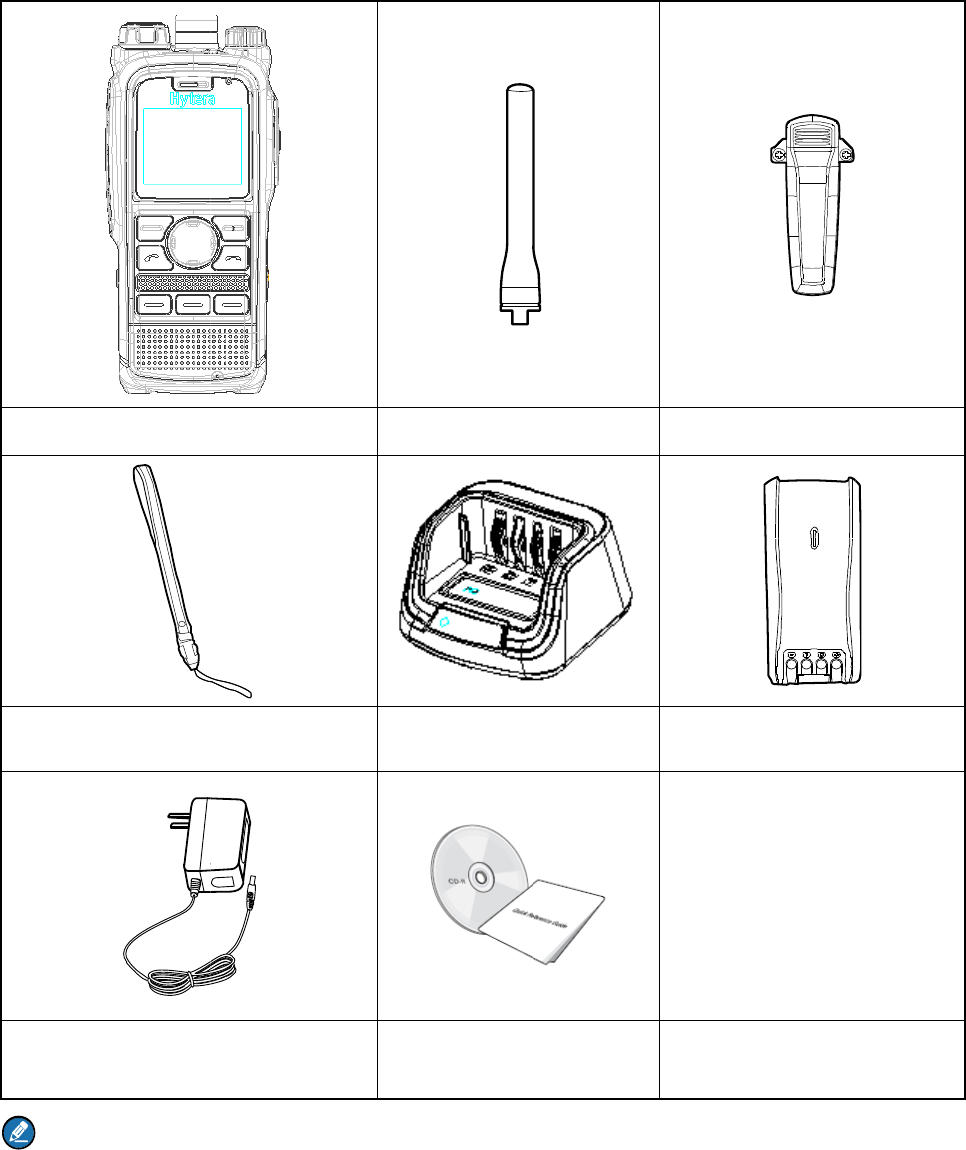
1. Ite
Please un
p
damaged,
p
Note
The fre
q
for freq
u
ms i
n
p
ack careful
l
p
lease cont
a
Termi
n
Stra
p
Power Ad
q
uency ban
d
u
ency band
n
the
P
l
y and chec
k
a
ct your de
a
n
al
p
apter
d
is marked
information
P
ack
a
k
if all items
a
ler.
on the labe
.
a
ge
listed belo
w
Anten
Char
g
Document
a
l of antenn
a
w
are receiv
e
na
g
e
r
a
tion Kit
a
; if not, ple
a
e
d. If any it
e
a
se refer to t
e
m is missin
Belt Clip
Battery
he label on
g or
the termina
l
l
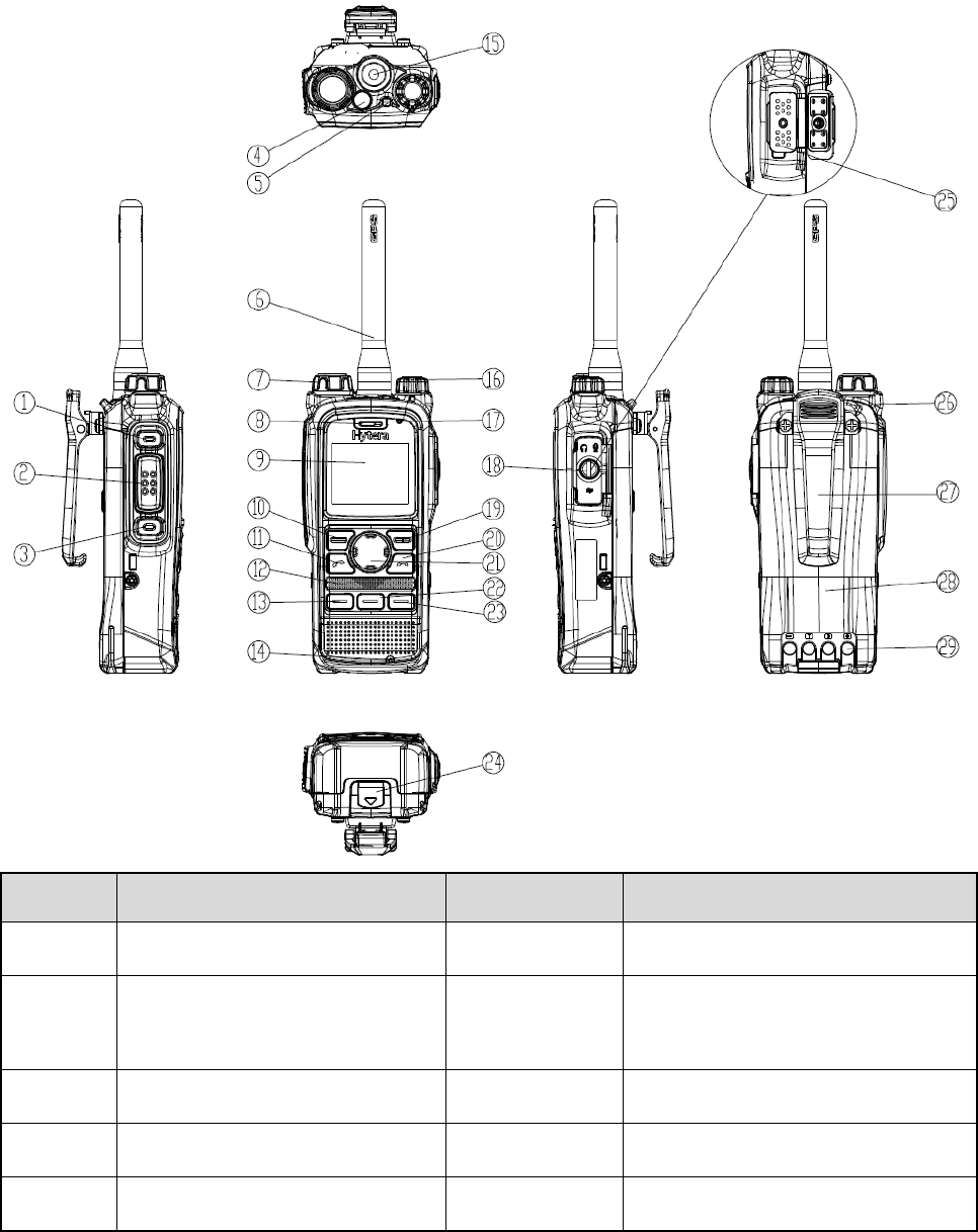
2. Product Overview
2.1 Product Controls
No. Part Name No. Part Name
○
1 SK1 (Side Key 1) ○
15 Antenna Connector
○
2 PTT (Push-to-Talk) Key ○
16
Power On-Off/Volume Control
Knob
○
3 SK2 (Side Key 2) ○
17 Half-duplex Microphone
○
4 Emergency Key ○
18 Accessory Connector Cover
○
5 LED Indicator ○
19 Options/Back Key
No.
○
6
○
7
○
8
○
9
○
10
○
11
○
12
○
13
○
14
Note
For en
h
F2Key
a
corresp
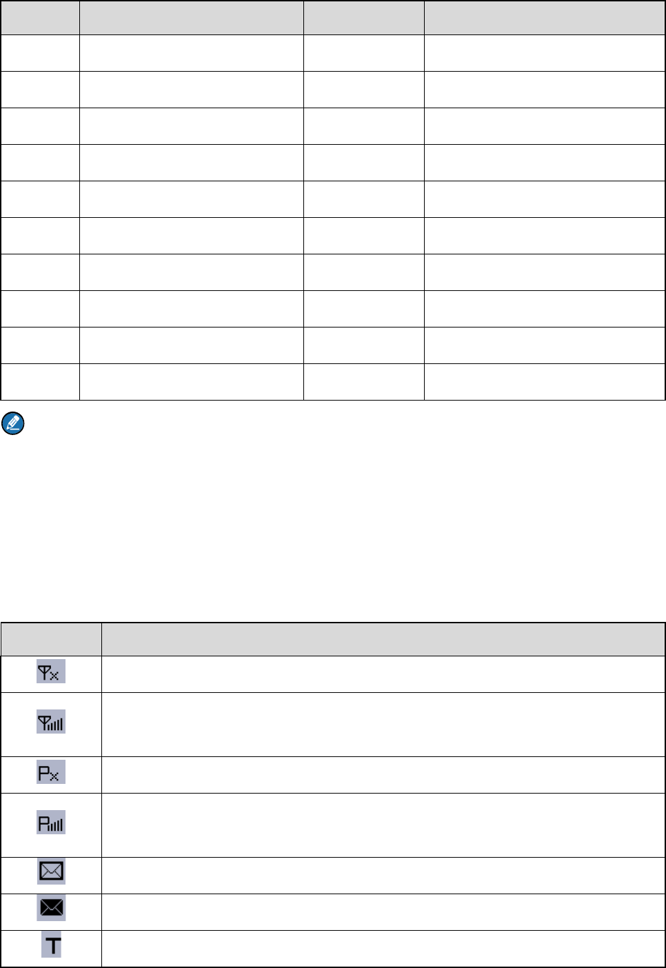
2.2
LC
Icon
Antenna
Group S
e
Full-dupl
e
LCD Dis
p
Func/OK
Answer/
C
Half-dupl
F1 Key
Full-dupl
e
h
anced con
v
a
ndF3Key
a
onding TE
T
D Icon
The t
e
The t
e
stren
g
The t
e
The t
e
more
Ther
e
The I
n
The t
e
Part Nam
e
lector Kno
b
e
x Receive
r
p
lay
Key
C
all Key
ex Speake
r
e
x Microph
o
v
enience, n
a
a
s shortcuts
T
RA Termin
a
e
rminal is n
o
e
rminal is
r
g
th.
e
rminal is n
o
e
rminal is
r
bars indica
t
e
is(are) unr
e
n
box is full.
e
rminal is o
p
e
b
o
ne
a
vigation ke
y
to certain f
e
a
l Series Fe
a
o
t registere
d
r
egistered
w
o
t registere
d
r
egistered
w
t
e stronger
s
e
ad messa
g
p
erating in
T
N
o
○
20
○
21
○
22
○
23
○
24
○
25
○
26
○
27
○
28
○
29
y
s, Call key,
e
atures. For
a
ture Book.
Term
i
d
with the s
y
w
ith the sys
t
d
with the s
y
w
ith the sys
t
s
ignal stren
g
g
e(s).
T
MO.
o
.
E
N
F
2
F
3
B
A
S
B
B
C
OK key, B
a
the detaile
d
i
nal Status
y
stem (appli
c
t
em, and
m
y
stem while
t
em while t
h
g
th.
P
nd Key
avigation K
e
2
Key
3
Key
attery Latc
h
ccessory C
o
trap Hole
elt Clip
attery
harging Pie
a
ck key, SK
1
d
introductio
c
able for T
M
m
ore bars in
the WAP br
h
e WAP br
o
P
art Name
e
y
h
o
nnecto
r
ce
1
and SK2
k
n, please r
e
M
O only).
dicate stro
n
owser is ru
n
o
wser is ru
n
k
ey ,F1Key
、
e
fer to the
n
ger signal
n
ning.
n
ning, and
、
Icon
The t
e
The t
e
The s
The s
The t
e
The t
e
The t
e
An a
u
An a
u
A pal
m
The
G
The
G
A wir
e
The
B
A wir
e
A call
The t
e
A gat
e
A gat
e
A rep
e
A rep
e
The
k
The
S
The
m
AIE (
A
E2E
E
e
rminal is o
p
e
rminal is o
p
can feature
can feature
e
rminal is o
p
e
rminal is o
p
e
rminal is o
p
u
dio access
o
u
dio access
o
m
micropho
n
G
PS feature
G
PS feature
e
less acces
s
B
T feature i
s
e
less acces
s
is in progr
e
e
rminal is s
e
e
way devic
e
e
way devic
e
e
ater is ava
e
ater is ava
k
eypad is lo
c
S
IM card E2
E
m
icrophone
i
A
ir Interface
E
(End-to-En
p
erating in
D
p
erating in f
a
is enabled
i
is enabled
i
p
erating in
s
p
erating in
n
p
erating in
v
o
ry is conne
o
ry is conne
n
e with key
p
is active, a
n
is active, b
u
s
ory is conn
s
enabled b
u
s
ory is conn
e
ss.
e
lecting a g
r
e
is availabl
e
e
is availabl
e
ilable and c
o
ilable but n
o
c
ked.
E
E is in us
e
i
s disabled.
Encryption
)
d Encryptio
Term
i
D
MO.
a
llback mo
d
i
n TMO.
i
n fallback
m
s
ilent mode.
n
ormal (ring
v
ibration mo
d
cted.
cted but no
t
p
ad is conn
e
n
d valid GP
S
u
t no valid
G
ected and
a
u
t no wirele
s
ected but n
o
r
oup.
e
and conn
e
e
but not co
n
o
nnected in
o
t connecte
d
e
.
)
is in use.
n) is in use.
i
nal Status
d
e.
m
ode.
and vibrati
o
d
e.
t
available f
o
e
cted.
S
or GLON
A
G
PS or GLO
a
vailable for
s
s accessor
y
o
t available
e
cted in DM
O
n
nected in
D
DMO.
d
in DMO.
o
n) mode.
o
r use.
A
SS data is
NASS data
use.
y
is connect
e
for use.
O
.
D
MO.
received.
is received.
e
d.
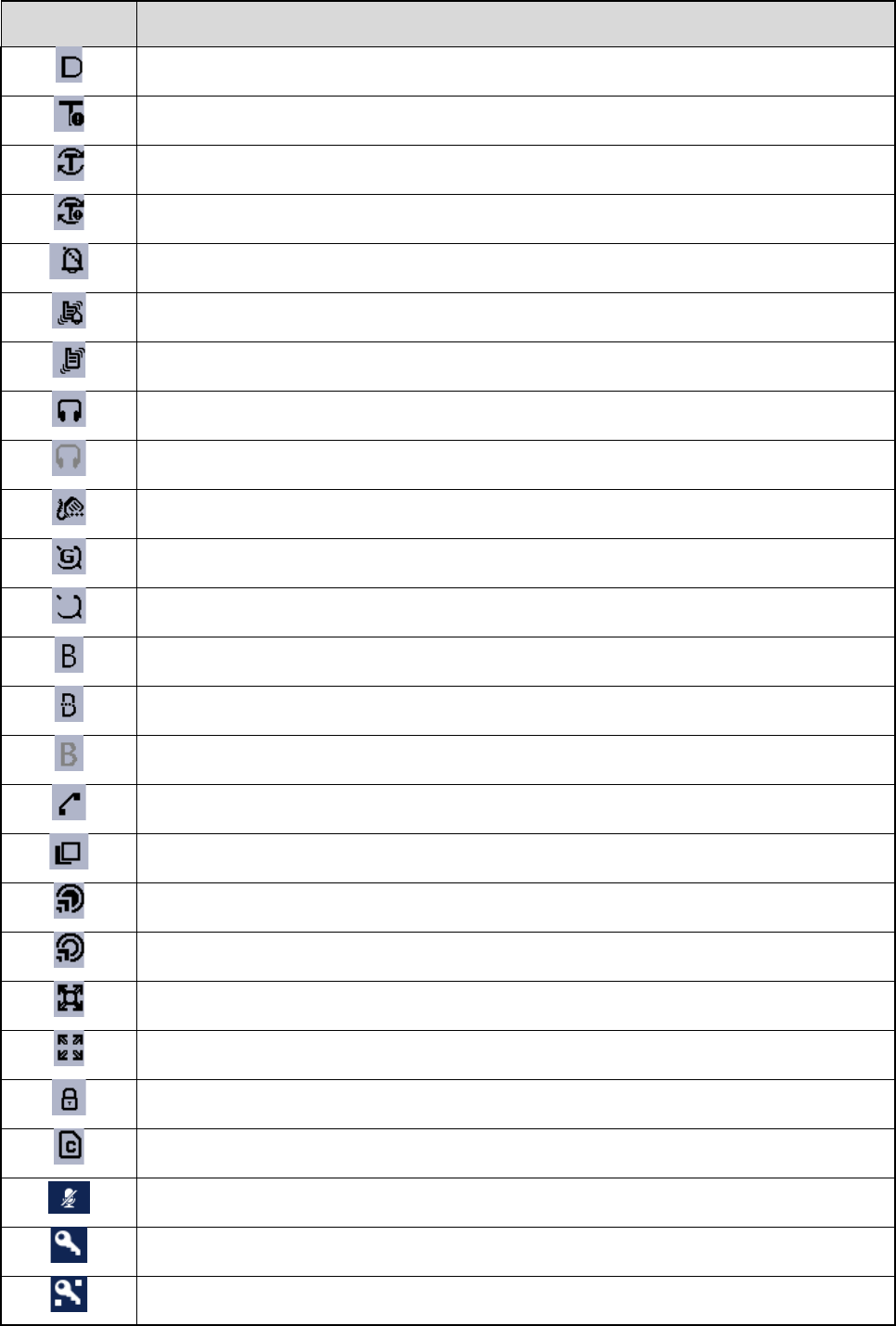
Icon Terminal Status
Both AIE and E2EE are in use.
The ongoing call enjoys a pre-emptive priority.
The ongoing call enjoys a higher priority.
The ongoing call enjoys a lower priority.
The terminal is prohibited from transmitting.
A call via gateway is in progress.
An E2EE call via gateway is in progress.
A call via repeater is in progress.
An E2EE call via repeater is in progress.
An AIE call via repeater is in progress.
The AIE and E2EE call via repeater is in progress.
An Emergency call is in progress.
A broadcast call is in progress.
2.3 LED Indicator
LED Indication Terminal Status
Glows red Transmitting
Flashes red slowly
Low battery voltage
Please replace or recharge the battery
Glows green Receiving
Flashes green slowly Channel idle in DMO
Glows orange
Channel busy in DMO
The terminal is prohibited from transmitting.
Flashes orange slowly The BS with which the terminal is registered is out of service in TMO.
3. Before Use
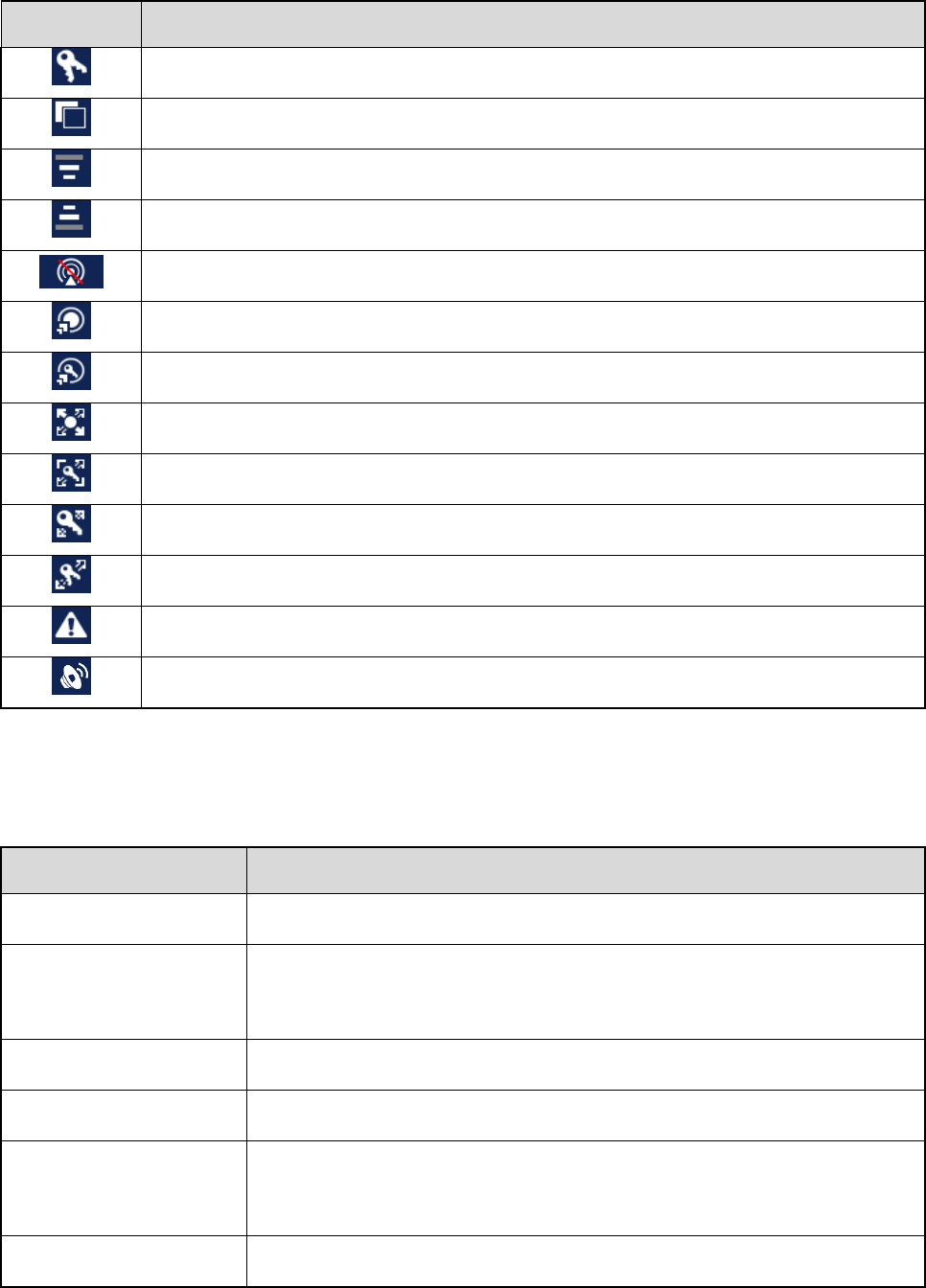
3.1 Attaching the Antenna
Caution
Do not hold the terminal by its antenna, otherwise the performance and lifespan of the antenna will be
reduced.
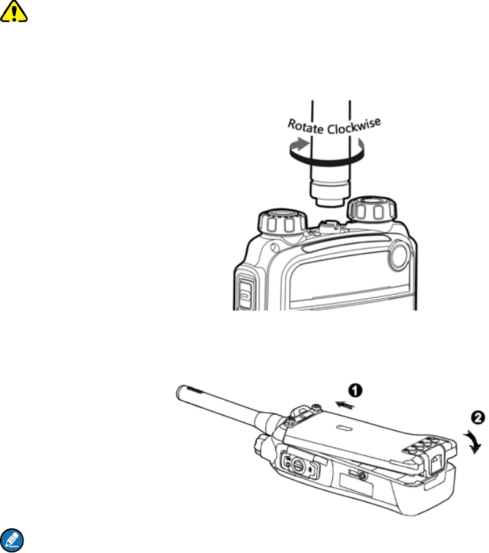
3.2 Attaching the Battery
Note
To remove the battery, turn off the terminal first. Then lift the battery latch and remove the battery.
3.3 Installing the SIM Card
If you have purchased the End-to-End Encryption (E2EE) feature which is realized via a SIM card,
please buy a SIM card and install it first.
Step 1 Remove the battery.
Step 2 Loosen the screw fixing the SIM card cover, open the cover, and then place the card into the
slot properly, as shown in the figure below.
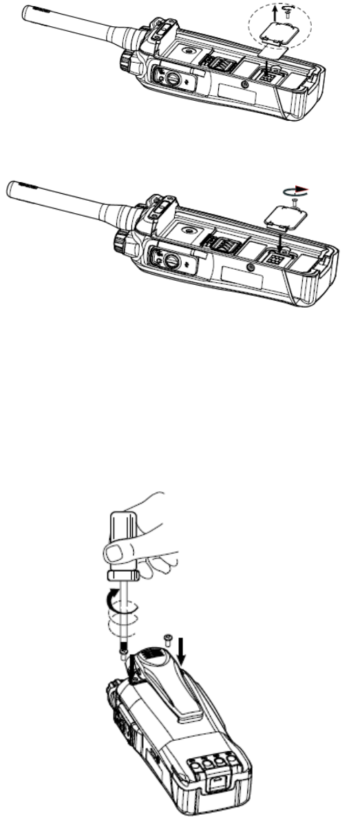
Step 3 Replace the cover and tighten the screw as shown in the figure below.
3.4 Attaching the Belt Clip
Step 1 Remove the two screws on the back of the terminal.
Step 2 Align the screw holes on the belt clip with those on the terminal, and then tighten the screws, as
shown in the figure below.
3.5 Attaching the Accessories
Step 1 Loosen the screw on the accessory connector cover, and open the cover as the arrow shows in
the figure below.
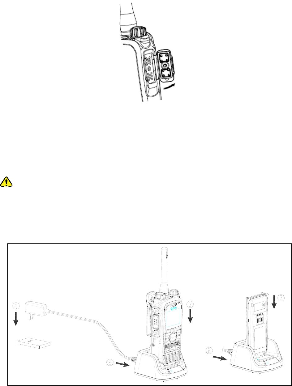
Step 2 Align the accessory (such as audio accessory and programming cable) plug with the accessory
connector.
Step 3 Secure the screw of the accessory.
3.6 Charging the Battery
Caution
Use the charger specified by the Company to charge the battery.
Make sure the terminal is powered off before charging. Read the Safety Information Booklet in
advance to get necessary safety information.
Charge a new battery for at least 5 hours before initial use for best performance.

Charging status indication on charger:
LED Indication Charging Status
Flashes red slowly Standby (no load)
Glows red Charging
Glows orange 90% charged
Glows green Fully charged
Flashes red rapidly Charging failed
4. Basic Operations
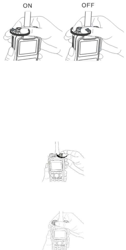
4.1 Turning On/Off the Terminal
4.2 Switching Operation Mode
This terminal can operate in either TMO or DMO.
Press the Func/OK key on the home screen to enter the “Mode” menu, and then select “TMO” or “DMO”
to switch the operation mode.
4.3 Adjusting the Call Volume
4.4 Selecting a Group
4.5 Managing the PhoneBook
PhoneBook is used to save the individual call number and PABX/PSTN number.
You can press the Func/OK key and go to “PhoneBook” menu to add, view, search, modify or delete
acontact.

5. TMO Service
The trunked mode operation (TMO) supports either half-duplex or full-duplex operation and allows the
terminals to communicate with each other via the TETRA network infrastructure. Thus features that
require network access are available. To operate in TMO mode, the terminal must be authorized by your
service provider, and must register with the network and stay within the network coverage.
5.1 Individual Call
An individual call is a half-duplex or full-duplex call initiated by an individual user to another individual
user. You can initiate and receive an individual call to/from an individual contact.
Initiating an Individual Call
Half-duplex Individual Call
Step 1 Press the Func/OK key and go to “PhoneBook” menu to select an individual contact.
Step 2 Hold down the PTT key to initiate a half-duplex individual call.
Step 3 Hold down the PTT key to talk after the call is established.
Full-duplex Individual Call
Step 1 Press the Func/OK key and go to “PhoneBook” menu to select an individual contact.
Step 2 Press to initiate a full-duplex individual call.
Step 3 Both parties can talk at any time without any operation after the call is established.
Answering an Individual Call
Half-duplex Individual Call
In case of an incoming call with Direct Signaling, the terminal will emit an alert tone to indicate that
the call is established successfully. At this time, no operation is required to answer the call.
In case of an incoming call with Hook Signaling, the terminal will ring and vibrate to indicate this
incoming call. At this time, press PTT to answer the call.
Hold down the PTT key to talk after the call is established.
Full-duplex Individual Call
In case of an incoming call with Direct Signaling, the terminal will emit an alert tone to indicate that
the call is established successfully. At this time, no operation is required to answer the call.
In case of an incoming call with Hook Signaling, the terminal will ring and vibrate to indicate this
incoming call. At this time, press PTT to answer the call.
Both parties can talk at any time without any operation after the call is established.

Ending an Individual Call
Press to end the call.
5.2 Group Call
A group call is a half-duplex call initiated by an individual user to other members in a predetermined
group. You can initiate a group call to the default group, and receive group calls from the members of the
group.
Initiating a Group Call
On the home screen, rotate the Group Selector knob to select a group and hold down the PTT key to
initiate a group call to this group, whose number is displayed on the home screen.
Answering a Group Call
You can answer a group call without any operation.
Ending/Exiting a Group Call
The calling party can press to end the group call.
The called party can press to exit the group call.
5.3 PABX/PSTN Call
A PABX/PSTN call is a full-duplex individual call with Hook Signaling established between an individual
user and a PABX or PSTN user outside the TETRA network.
The operations for initiating a PABX/PSTN call are as follows. For operations of answering or ending a
PABX/PSTN call, refer to 5.1Individual Call.
Initiating a PABX/PSTN Call
Step 1 On the home screen, press the Func/OK key to go to “Settings -> Network” and select “PSTN
GW” or “PABX GW”.
Step 2 Return to the home screen and input a PABX or PSTN number.
Step 3 Press the Func/OK key to select “PABX” or “PSTN” if appears on the screen.
Skip this step if does not appear on the screen.
Step 4 Press to initiate the call.
5.4 Emergency Call
An Emergency call is a call initiated by an individual user to the predefined contact for summoning help
in urgent situations. With the highest priority, it can interrupt any other ongoing calls with lower priority if
no resource is available.
Initiating an Emergency Call
Hold down the Emergency key for the preset time to initiate an emergency call to the predefined contact
which can be the individual, group, PABX or PSTN user.
Answering an Emergency Call
You can answer an emergency individual call or emergencygroup call without any operation.
As for an emergency PABX/PSTN call, you need to press the PTT key to answer the call.
Ending/Exiting an Emergency Call
For ending operation, refer to 5.1Individual Call, 5.2Group Callor PABX/PSTN Callaccording to the
predefined contact.
5.5 Message Service
Message Service allows you to send and receive a message, which includes Status Message and User
Message. Status Message is programmed by your dealer only while User Message allows you to create,
edit and send a text message.
Sending a Message
Step 1 Press the Func/OK key to go to “Message -> New Msg” and select “Status Msg”.
Step 2 For status message, select “View -> Options” and then select “Individual” or “Group”; for user
message, press Func/OK key to select “Individual” or “Group” after editing the message.
Step 3 Enter the individual number or select a group contact, and press the Func/OK key to send the
message.
Viewing a Message
Step 1 On the home screen, press the Func/OK key to go to “Message -> Inbox”, and select the
appropriate message.
Step 2 Press the Func/OK key to view the content.

6. DMO Service
The direct mode operation (DMO) supports half-duplex operation and allows the terminals to
communicate directly with each other, without using a TETRA network infrastructure. Thus features that
require network access will be unavailable.
6.1 Individual Call
An individual call is a half-duplex call initiated by an individual user to another individual user. You can
initiate and receive an individual call to/from an individual contact.
Initiating an Individual Call
Step 1 Press the Func/OK key and go to “PhoneBook” menu to select an individual contact.
Step 2 Hold down the PTT key to initiate the call.
Step 3 Hold down the PTT key to talk after the call is established.
Answering an Individual Call
You can answer the call without any operation.
Ending an Individual Call
Press to end the call.
6.2 Group Call
The group call operations in DMO are similar to those in TMO. Refer to 5.2Group Call for details.
6.3 Emergency Call
An Emergency call is a call initiated by an individual user to the default group for summoning help in
urgent situations. With the highest priority, it can interrupt any other ongoing calls with lower priority if no
resource is available.
Initiating an Emergency Call
Hold down the Emergency key for the preset time to initiate an emergency call to the default group.
Answering an Emergency Call
You can answer an emergency individual call or group call without any operation.
Ending/Exiting an Emergency Call
The calling party can press to end the Emergency call.
The called party can press to exit the Emergency call.
6.4 Message Service
The message operations in DMO are similar to those in TMO. Refer to 5.5Message Service for details.

7. Troubleshooting
Phenomenon Analysis Solution
Terminals cannot be
powered on.
The battery power may be too low to
power on the terminal.
Charge the battery.
Network registration
fails or network
cannot be found.
The terminal may be operating in
DMO.
Switch to TMO.
The terminal may be out of the
network coverage in TMO.
Check the signal strength. Make
sure the terminal is within the
network coverage.
The terminal may not be granted
network access.
Contact the network operator for the
terminal authorization.
Calls cannot be
established.
The terminal or the called party may
be out of the network coverage.
Check the signal strength. Make
sure the terminal is within the
network coverage.
The terminal may operate in an
improper mode.
Check the operation mode. Make
sure the terminal works in the right
mode.
A certain group call
cannot be initiated or
received.
The terminal may not be a member of
the target group.
Check whether the terminal is a
member of the group. If not, contact
your dealer to add the terminal to the
group.
The terminal may not be authorized to
access the target group.
Contact the network operator for the
terminal authorization.
Calls are always
interrupted.
The current channel may be assigned
to emergency calls or other calls with
higher priority.
Wait until the channel becomes
available and try again.
A half-duplex call
cannot be
established.
The predefined time period for
establishing a call may expire.
Make sure the call is established
within the predefined time period.
The channel may be occupied by Wait until the channel becomes

another terminal with higher call
priority.
available and try again.
The channel resources may be
allocated to other services due to
overloaded network.
Wait until the channel becomes
available and try again.
Abnormal
disconnection occurs
during a call.
The terminal may be out of the
network coverage in TMO.
Check the signal strength. Make
sure the terminal is within the
network coverage.
The terminal may operate at an
unfavorable position where
communication may be blocked by
high buildings or frustrated in the
underground areas in DMO.
Move to an open and flat area, and
restart the terminal.
As for the same
status message ID,
the content displayed
at the receiving party
is different from that
of the sending party.
The parties may have associated the
same status message ID with
different contents.
Make sure the status message ID is
associated with the same content.
If the above solutions cannot fix your problems, or you may have some other queries, please contact us
or your local dealer for more technical support.

8. Care and Cleaning
To guarantee optimal performance as well as a long service life of the product, please follow the tips
below.
Product Care
Do not pierce or scrape the product.
Keep the product far away from substances that can corrode the circuit.
Do not hold the product by its antenna or earpiece cable directly.
Attach the accessory connector cover when the product is not in use.
Product Cleaning
Caution
Power off the product and disconnect the power supply before cleaning.
Clean up the dust and fine particles on the product surface and charging piece with a clean and dry
lint-free cloth or a brush regularly.
Use neutral cleanser and a non-woven fabric to clean the keys, control knobs and front case after
long-time use. Do not use chemical preparations such as stain removers, alcohol, sprays or oil
preparations, so as to avoid surface case damage.
Make sure the product is completely dry before use.

9. Optional Accessories
Please contact your local dealer or us for more details on the main optional accessories of the product.
Caution
Use the accessories specified by the Company only. If not, the Company shall not be liable for any
losses or damages arising out of use of unauthorized accessories.
10. FCC STATEMENT
This device complies with Part 15 of the FCC Rules. Operation is subject to the following
two conditions:
(1) This device may not cause harmful interference, and
(2) this device must accept any interference received, including interference that may
cause undesired operation.
NOTE 1: This equipment has been tested and found to comply with the limits for a Class
B digital device, pursuant to part 15 of the FCC Rules. These limits are designed to
provide reasonable protection against harmful interference in a residential installation.
This equipment generates, uses and can radiate radio frequency energy and, if not
installed and used in accordance with the instructions, may cause harmful interference to
radio communications. However, there is no guarantee that interference will not occur in
a particular installation. If this equipment does cause harmful interference to radio or
television reception, which can be determined by turning the equipment off and on, the
user is encouraged to try to correct the interference by one or more of the following
measures:
- Reorient or relocate the receiving antenna.
- Increase the separation between the equipment and receiver.
-Connect the equipment into an outlet on a circuit different from that to which the
receiver is connected.
-Consult the dealer or an experienced radio/TV technician for help.
NOTE 2: Any changes or modifications to this unit not expressly approved by the party
responsible for compliance could void the user's authority to operate the equipment.
IC STATEMENT
This device complies with Industry Canada licence-exempt RSS standard(s): Operation is
subject to the following Two conditions:(1) this device may not cause interference, and
(2) this device must accept any interference, including interference that may cause
undesired operation of the device.
Le présentappareilestconforme aux CNR d'Industrie Canada applicables aux appareils
radio exempts de licence. L'exploitationestautorisée aux deux conditions suivantes : (1)
l'appareil ne doit pas produire de brouillage, et (2) l'utilisateur de l'appareildoit accepter
toutbrouillageradioélectriquesubi, mêmesi le brouillageest susceptible d'en
compromettre le fonctionnement.
The information listed above provides the user with information needed to make him or her aware of a
RFexposure, and what to do to assure that this radio operates within the FCC exposure limits of this
radio. SAR compliance for body-worn operating configurations is limited to the specific belt clip/ holster/
accessories tested for this product.
The device complies with RF specifications when the device used at 25mm from your front face and
0mm from your body, Third-party belt-clips, holsters, and similar accessories used by this device should
not contain any metallic components. Body-worn accessories that do not meet these requirements may
not comply with RF exposure requirements and should be avoided.Maximun SAR Value (1g): 2.34W/Kg.