Hytera Communications RD62XU1 Digital Wall-mounted Repeater User Manual YAMRD62XU1
Hytera Communications Corporation Ltd. Digital Wall-mounted Repeater YAMRD62XU1
YAMRD62XU1_User Manual
Preface
Thanks for your favor in our product. To derive optimum performance from the product, please read this
manual and the Safety Information Booklet carefully before use.
This manual is applicable to the following product:
RD620 Repeater

Instructional Icons
Caution: Indicates situations that could cause damage to your product or bodily injury.
Note: Indicates tips that can help you make better use of your product.
Term Explanation
Voltage Standing Wave Ratio (VSWR)
Voltage Standing Wave Ratio (VSWR) is a value that measures how well a load is impedance-matched
to a source.
Copyright Information
Hytera is the trademark or registered trademark of Hytera Communications Co., Ltd. (the Company) in
PRC and/or other countries or areas. The Company retains the ownership of its trademarks and product
names. All other trademarks and/or product names that may be used in this manual are properties of
their respective owners.
The product described in this manual may include the Company’s computer programs stored in memory
or other media. Laws in PRC and/or other countries or areas protect the exclusive rights of the Company
with respect to its computer programs. The purchase of this product shall not be deemed to grant, either
directly or by implication, any rights to the purchaser regarding the Company’s computer programs. Any
of the Company’s computer programs may not be copied, modified, distributed, decompiled, or
reverse-engineered in any manner without the prior written consent of the Company.
The AMBE+2TM voice coding technology embodied in this product is protected by intellectual property
rights including patent rights, copyrights and trade secrets of Digital Voice Systems, Inc. This voice
coding technology is licensed solely for use within this product. The user of this technology is explicitly
prohibited from attempting to decompile, reverse engineer, or disassemble the Object Code or in any
other way convert the Object Code into a human-readable format.
U.S. Patent No: #6,912,495 B2, #6,199,037 B1, #5,870,405, #5,826,222, #5,754,974, #5,701,390,
#5,715,365, #5,649,050, #5,630,011, #5,581,656, #5,517,511, #5,491,772, #5,247,579, #5,226,084 and
#5,195,166.
Disclaimer
The Company endeavors to achieve the accuracy and completeness of this manual, but no warranty of
accuracy or reliability is given. All the specifications and designs are subject to change without notice
due to continuous technology development. No part of this manual may be copied, modified, translated,
or distributed in any manner without the express written permission of us.
We do not guarantee, for any particular purpose, the accuracy, validity, timeliness, legitimacy or
completeness of the Third Party products and contents involved in this manual.
If you have any suggestions or would like to learn more details, please visit our website at:
http://www.hytera.com.
RF Radiation Information
This product must be restricted to operations in an Occupational/Controlled RF exposure Environments.
Users must be fully aware of the hazards of the exposure and able to exercise control over their RF exposure
to qualify for the higher exposure limits.
RF Radiation Profile
Radio Frequency (RF) is a frequency of electromagnetic radiation in the range at which radio signals are
transmitted. RF technology is widely used in communication, medicine, food processing and other fields.
It may generate radiation during use.
RF Radiation Safety
In order to ensure user health, experts from relevant industries including science, engineering, medicine
and health work with international organizations to develop standards for safe exposure to RF radiation.
These standards consist of:
z United States Federal Communications Commission, Code of Federal Regulations; 47CFR part 2
sub-part J;
z American National Standards Institute (ANSI)/Institute of Electrical and Electronic Engineers (IEEE)
C95. 1-1992;
z Institute of Electrical and Electronic Engineers (IEEE) C95.1-1999;
z International Commission on Non-Ionizing Radiation Protection (ICNIRP) 1998.

FCCRegulations
FederalCommunicationCommission(FCC)requiresthatallradiocommunicationproductsshould
meettherequirementssetforthintheabovestandardsbeforetheycanbemarketedintheU.S,
andthemanufacturershallpostaRFlabelontheproducttoinformusersofoperational
instructions,soastoenhancetheiroccupationalhealthagainstexposuretoRFenergy.
Thisdevicecomplieswithpart15oftheFCCRules.Operationissubjecttotheconditionthatthis
devicedoesnotcauseharmfulinterference.
ThemanufacturerisnotresponsibleforanyradioorTVinterferencecausedbyunauthorized
modificationstothisequipment.suchmodificationscouldvoidtheuser'sauthoritytooperate
thisequipment.
ThisequipmenthasbeentestedandfoundtocomplywiththelimitsforaClassBdigitaldevice,
pursuanttopart15oftheFCCRules.Theselimitsaredesignedtopro‐videreasonableprotection
againstharmfulinterferenceinaresidentialinstallation.Thisequipmentgenerates,usesandcan
radi‐ateradiofrequencyenergyand,ifnotin‐stalledandusedinaccordancewiththe
in‐structions,maycauseharmfulinterferencetoradiocommunications.However,thereisno
guaranteethatinterferencewillnotoccurinaparticularinstallation.Ifthisequip‐mentdoes
causeharmfulinterferencetoradioortelevisionreception,whichcanbedeterminedbyturning
theequipmentoffandon,theuserisencouragedtotrytocorrecttheinterferencebyoneor
moreofthefol‐lowingmeasures:
● Reorientorrelocatethereceivingantenna.
● Connecttheequipmentintoanoutletonacircuitdifferentfromthattowhichthereceiveris
connected.
● Consultthedealeroranexperiencedradio/TVtechnicianforhelp.
OperationalInstructionsandTrainingGuidelines
Toensuretheoptimalperformanceandthecompliancewithoccupational/controlled
environmentRFradiancelimitsintheabovestandards,pleaseadheretothefollowing
requirements:
● Whenyouareinstallingtheproductantennaoutside,setuptheantennaaccordingtothe
supplier’srequirementswithitsGainwithin3.50dBiandkeepitatleast1.08metersaway
fromhumanbody.
● Notuseddutycycleover100%.
CanadaRegulations
ThedevicecomplieswithSARand/orRFfieldstrengthlimitsofRSS‐102requirement。
EURegulatoryConformance
Theequipmentisincompliancewiththeessentialrequirementsandotherrelevantprovisionsof
theDirective1999/5/EC.
Contents
1. Checking Items in the Package ........................................................................................................... 1
2. Product Introduction ............................................................................................................................ 2
2.1 Parts ................................................................................................................................................. 2
2.2 Front Panel ....................................................................................................................................... 3
2.3 Rear Panel ........................................................................................................................................ 4
3. Status Indication .................................................................................................................................. 5
4. Before Use ............................................................................................................................................ 6
4.1 Instruction ......................................................................................................................................... 6
4.2 Wall-mount Bracket Installation (Optional) ........................................................................................ 6
5. Alarm Information ................................................................................................................................ 9
6. Troubleshooting ................................................................................................................................. 10
7. Care and Cleaning .............................................................................................................................. 11
8. Optional Accessories ......................................................................................................................... 12
1
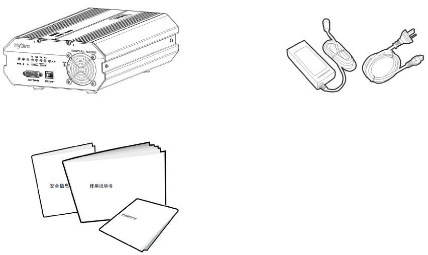
1. Checking Items in the Package
Please unpack carefully and check that all items listed below are received. If any item is missing or
damaged, please contact your dealer.
Repeater AC Power Cord
Documentation Kit
2
2. Product Introduction
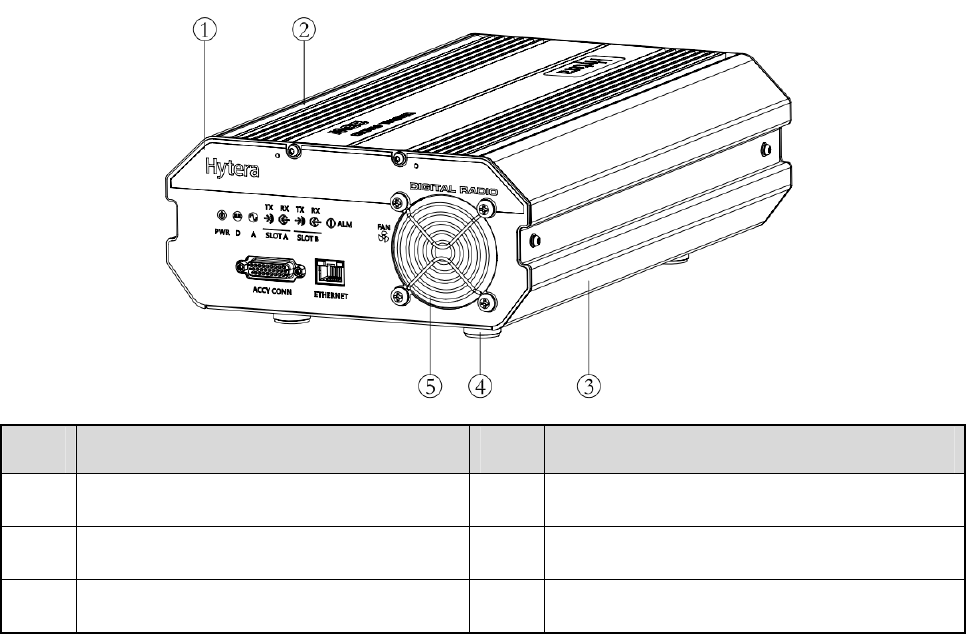
2.1 Parts
No. Part Name No. Part Name
1 Front Panel 4 Foot Pad
2 Upper Cover 5 Fan Mesh Enclosure
3 Chassis / /
3
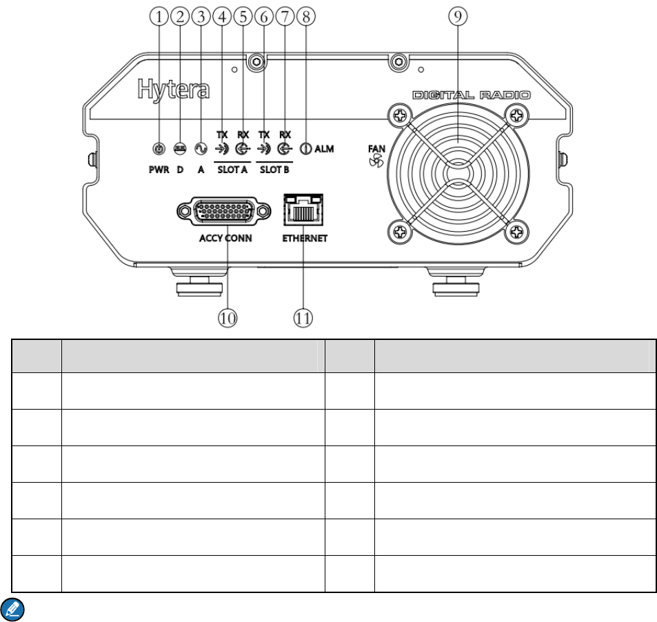
2.2 Front Panel
No. Part Name No. Part Name
1 Power Indicator 7 Slot B RX Indicator
2 Digital Mode Indicator 8 Alarm Indicator
3 Analog Mode Indicator 9 Fan Inlet
4 Slot A TX Indicator 10 D-SUB Data Interface
5 Slot A RX Indicator 11 RJ45 Data Interface
6 Slot B TX Indicator / /
Note:
If the repeater is manufactured without internal duplexer, then part 8 will be an external duplexer RX
port; if it is manufactured with internal duplexer, then there is no connection inside part 8.
4
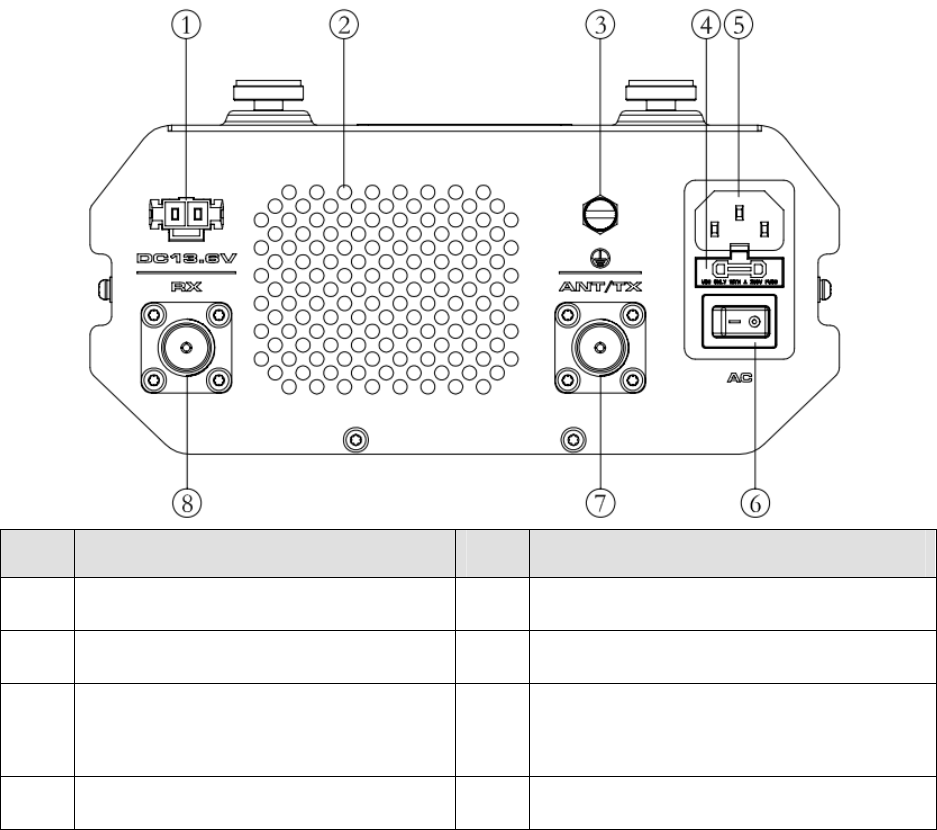
2.3 Rear Panel
No. Part Name No. Part Name
1 DC Power Inlet 5 AC Power Inlet
2 Fan Outlet 6 AC Power Switch
3 Ground Terminal 7 ANT/TX Antenna Connector (N-type
Female)
4 Fuse Box 8 RX Antenna Connector (N-type Female)

5
3. Status Indication
LED indicators on the front panel indicate the following repeater status:
LED Indicator Name LED Indicator
Status Repeater Status
Digital Mode Indicator Blue The repeater is operating in digital mode.
Analog Mode Indicator Yellow The repeater is operating in analog mode.
Slot A TX Indicator Red
z Analog Mode: The repeater is transmitting.
z Digital Mode: Slot A is transmitting.
Slot A RX Indicator Green
z Analog Mode: The repeater is receiving.
z Digital Mode: Slot A is receiving.
Slot B TX Indicator Red Digital Mode: Slot B is transmitting.
Slot B RX Indicator Green Digital Mode: Slot B is receiving.
Alarm Indicator Red Alarm alert indication will remain until all alarms
are eliminated.
6
4. Before Use
4.1 Instruction
To ensure optimum performance and reliability of the repeater, please read the following instructions
carefully.
Operation Environment
The repeater must be installed in a dry and well-ventilated place with ambient temperature of -30 ℃ to
+60℃ and relative humidity of not more than 95%.
Voltage Check
Check whether the input voltage is within the operating voltage of the repeater (DC power supply: 13.6V
±15%; AC power supply: 90V to 264V).
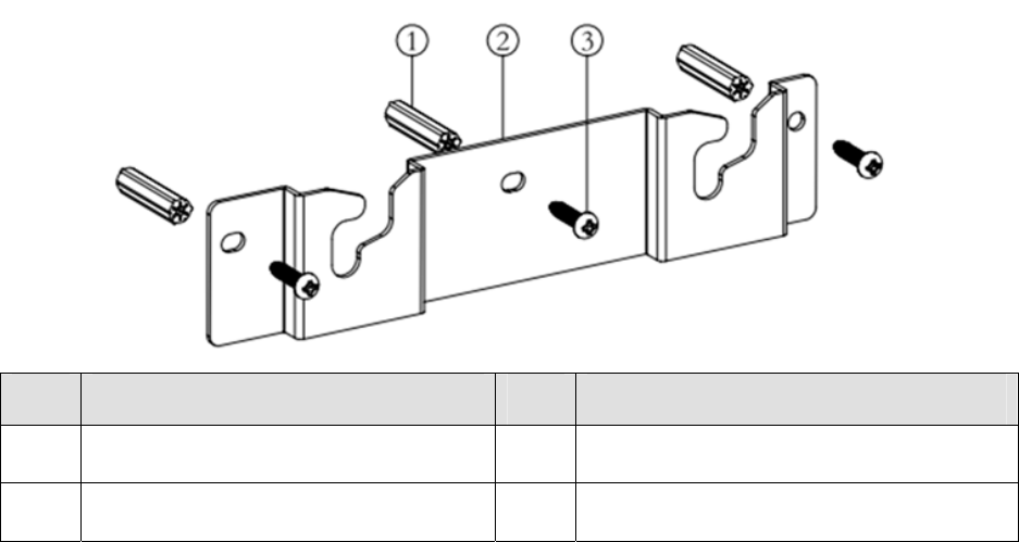
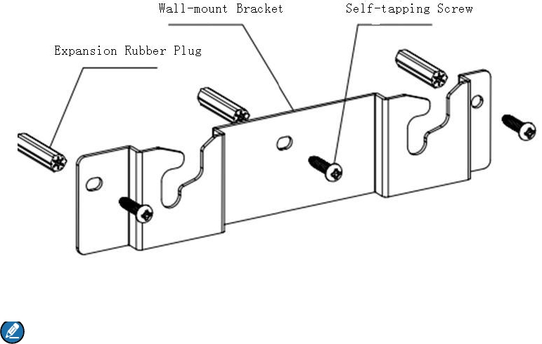
4.2 Wall-mount Bracket Installation (Optional)
Please contact your dealer to purchase a wall-mount bracket kit to install the repeater on the wall.
No. Part Name No. Part Name
1 Expansion Rubber Plug 3 Self-tapping Screw
2 Wall-mount Bracket / /
4.2.1 Installation Tools
Tools required for installing the repeater include an electric drill and a T10 torx screwdriver.
4.2.2 Installation Steps
Step 1 To install the wall-mount bracket, do as follows:
7
1. Use the electric drill to drill three holes on the wall which align with that on the wall-mount
bracket;
2. Put the expansion rubber plug into the drill holes; you can ignore this step if the wall is not a
concrete wall;
3. Use three ST4X16 self-tapping screws to fasten the bracket on the wall.
Note: Make sure the wall can support the repeater’s weight before drilling.
8
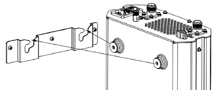
Step 2 To amount the repeater on the bracket, do as follows:
1. Align the hanging screws on the upper side of the repeater with the notch of the bracket and
hang the repeater on the bracket;
2. Move the repeater side to side slightly to ensure the hanging screws reach the bottom of the
notch.
4.2.3 Product Check
Please check whether the repeater works properly by observing the 7 LEDs located in the front panel
after the repeater is powered on via the AC Power Switch key.

9
5. Alarm Information
The repeater will have real-time detection of its status automatically. When the repeater is operating
abnormally, the alarm indicator on the front panel will remain glowing red until all alarms are eliminated.
When an alarm event occurs, you can diagnose and handle the problem via the RDAC application
provided by us or contact your local dealer for technical support.
Alarm types and causes are listed in the table below:
Alarm Type Alarm Cause
External Power
Abnormal
High Voltage: The input voltage is higher than 15.8V±0.2V.
Low Voltage: The input voltage is lower than 11V±0.2V.
High Temperature Temperature sensor detects a temperature above 85℃.
Abnormal VSWR VSWR > 3:1.
Over-high VSWR will damage the PA module or even disable it.
TX Unlock TX PLL is unlocked, and the repeater stops transmitting and repeating.
RX Unlock RX PLL is unlocked, and the repeater stops receiving and repeating.
Fan Failure PA temperature is higher than the fan off temperature configured via CPS.

10
6. Troubleshooting
Phenomena Analysis Solution
Power-on Failure.
The power cord may be
unconnected or not securely
connected to the outlet.
Properly connect the power cord and
ensure secure connection.
The power supply may output
improper voltage.
Check if the power supply outputs the
voltage within the required range (DC
power supply: 13.6V ±15%; AC power
supply: 90V to 264V). If not, replace the
power adapter.
Unable to
communicate with
other members.
TX/RX frequency of the repeater
is inconsistent with that of
portable/mobile radios.
Check if the frequencies are consistent.
Reset the frequencies when necessary.
Failed to repeat useful signal due
to strong interference signals.
If you cannot remove or bypass the
interference source, change to operate at
other frequencies.
The group member is out of the
coverage of the repeater.
Move towards the coverage of the
repeater.
If the above solutions cannot fix the problems, or there are other questions, please contact Hytera or the
dealer for more technical support.

11
7. Care and Cleaning
To guarantee optimal performance as well as a long service life of the repeater, please follow the tips
below.
Product Care
z Keep the repeater in good environmental conditions to ensure reliability.
z Do not place other equipment on top of the repeater to ensure optimal heat dissipation.
z Do not pierce or scrape the product.
z Keep the product far away from corrosive environments.
z Do not place the product in corrosive agents, solutions or water.
Product Cleaning
Caution: Be sure to turn off the repeater before cleaning.
z Remove the dust and fine particles on the repeater surface with a clean and dry lint-free cloth or a
brush regularly.
z Use a non-woven fabric with neutral cleanser to clean the keys, control knobs, LCD and connectors.
Do not use chemical preparations such as stain removers, alcohol, sprays or oil preparations. Make
sure the repeater is completely dry before use.
12
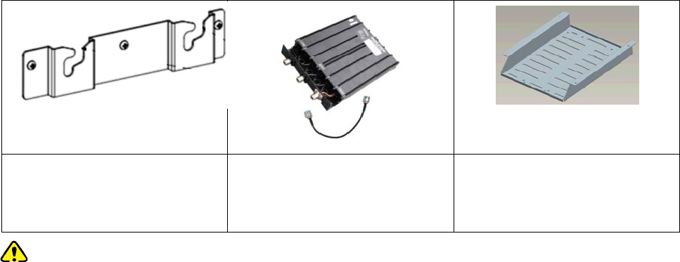
8. Optional Accessories
The following items are the main optional accessories for the repeater, and please consult your local
dealer for more other accessory information.
Wall-mount Bracket
BRK21
Duplexer Duplexer Mounting Bracket
Caution: Use the accessories specified by the Company only. If not, Hytera shall not be liable for
any losses or damages arising out of use of unauthorized accessories.