Hytera Communications RD96XU1 Digital Portable Repeater User Manual
Hytera Communications Corporation Ltd. Digital Portable Repeater Users Manual
YAMRD96XU1_User Manual
Preface
Thanks for your favor in our product. To derive optimum performance from the product, please read this
manual and the supplied Safety Information Booklet carefully before use.
This manual is applicable to the following model:
RD96X(X may represent 2, 5, 6 or 8)

Instructional Icons
The following icons are available through this manual:
The radio is not intended for use by general population in an uncontrolled environment. It is only for
occupational use and only applied to work-related conditions.The radio must be only used by users, who
are fully aware of the hazards of the exposure and who are able to exercise control over their RF
exposure to qualify for the higher exposure limits.
Alert Icons
Caution: indicates situations that could cause damage to your product or bodily injury.
Note: indicates tips that can help you make better use of your product.
*: indicates functions available in later version.
Term Explanation
Key Operation
z Short press: to press a key and release it quickly.
z Long press: to press a key and remain holding it down for a predefined period (2 seconds by default).
Hold down: to press a key and remain holding it down.
Duplexer
Duplexer is a device that allows bi-directional communication. Its role is to isolate the TX signal from the
RX signal to ensure that the transmitter and receiver can work normally. It consists of two groups of
band-stop filters with different frequencies, to prevent it from transmitting the signals to the receiver.
Feed Line
Feed Line is the cable or transmission line that connects the antenna with the radio transmitter or
receiver.
Voltage Standing Wave Ratio (VSWR)
Voltage Standing Wave Ratio (VSWR) is a value that measures how well a load is impedance-matched
to a source.
Squelch
Squelch is a circuit function that acts to suppress the audio output of a receiver in the absence of a
sufficiently strong desired input signal.
Copyright Information
Hytera is the trademark or registered trademark of Hytera Communications Co., Ltd. (the Company) in
PRC and/or other countries or areas. The Company retains the ownership of its trademarks and product
names. All other trademarks and/or product names that may be used in this manual are properties of
their respective owners.
The product describes in this manual may include the Company’s computer programs stored in memory
or other media. Laws in PRC and/or other countries or areas protect the exclusive rights of the Company
with respect to its computer programs. The purchase of this product shall not be deemed to grant, either
directly or by implication, any rights to the purchaser regarding the Company’s computer programs. Any
of the Company’s computer programs may not be copied, modified, distributed, decompiled, or
reverse-engineered in any manner without the prior written consent of the Company.
The AMBE+2TM voice coding technology embodied in this product is protected by intellectual property
rights including patent rights, copyrights and trade secrets of Digital Voice Systems, Inc.This voice
coding technology is licensed solely for use within this product. The user of this technology is explicitly
prohibited from attempting to decompile, reverse engineer, or disassemble the Object Code or in any
other way convert the Object Code into a human readable form.
U.S. Patent No: #6,912,495 B2, #6,199,037 B1, #5,870,405, #5,826,222, #5,754,974, #5,701,390,
#5,715,365, #5,649,050, #5,630,011, #5,581,656, #5,517,511, #5,491,772, #5,247,579, #5,226,084 and
#5,195,166.
Disclaimer
The Company endeavors to achieve the accuracy and completeness of this manual, but no warranty of
accuracy or reliability is given. All the specifications and designs are subject to change without notice
due to continuous technology development. No part of this manual may be copied, modified, translated,
or distributed in any manner without the express written permission of us.
We do not guarantee, for any particular purpose, the accuracy, validity, timeliness, legitimacy or
completeness of the Third Party products and contents involved in this manual.
If you have any suggestions or would like to learn more details, please visit our website at:
http://www.hytera.com.
RF Radiation Information
RF Radiation Profile
Radio Frequency (RF) is a frequency of electromagnetic radiation in the range at which radio signals are
transmitted. RF technology is widely used in communication, medicine, food processing and other fields.

It may generate radiation during use.
RF Radiation Safety
In order to ensure user health, experts from relevant industries including science, engineering, medicine
and health work with international organizations to develop standards for safe exposure to RF radiation.
These standards consist of:
z United States Federal Communications Commission, Code of Federal Regulations; 47CFR part 2
sub-part J;
z American National Standards Institute (ANSI)/Institute of Electrical and Electronic Engineers (IEEE)
C95. 1-1992;
z Institute of Electrical and Electronic Engineers (IEEE) C95.1-1999;
z International Commission on Non-Ionizing Radiation Protection (ICNIRP) 1998.
Operational Instructions and Training Guidelines
To ensure optimal performance and compliance with the occupational/controlled environment RF energy
exposure limits in the above standards and guidelines, users should transmit no more than 50% of the
time and always adhere to the following procedures when in PTT mode and transmit should no more
than 100% of time when in repeater mode.
FCC Regulations
Federal Communication Commission (FCC) requires that all radio communication products should meet
the requirements set forth in the above standards before they can be marketed in the U.S, and the
manufacturer shall post a RF label on the product to inform users of operational instructions, so as to
enhance their occupational health against exposure to RF energy.
Operational Instructions and Training Guidelines
To ensure the optimal performance and the compliance with occupational/controlled environment RF
radiance limits in the above standards, please adhere to the following requirements:
z When you are carrying this product on your back, ensure the Gain of the antenna is not more than
3.5dBi, and the output power is within 5W.
z When you are installing the repeater antenna outside, set up the antenna according to the supplier’s
requirements with its Gain within 6.5dBi and keep it at least 0.5 meters away from human body.

EU Regulatory Conformance
As certified by the qualified laboratory, the product is in compliance with the essential requirements and
other relevant provisions of the Directive 1999/5/EC. Please note that the above information is applicable
to EU countries only.
Mobile repeater station
When automatically retransmit-ting messages originated by or destined for hand-carried units, each
mobile sta-tion shall activate the mobile trans-mitter only with a continuous access signal, the absence of
which will de-ac-tivate the mobile transmitter. The con-tinuous access signal is not required when the
mobile unit is equipped with a switch that activates the automatic mode of the mobile unit and an
auto-matic time-delay device that de-acti-vates the transmitter after any unin-terrupted transmission
period in excess of 3 minutes. For the purposes of this rule section the continuous access sig-nal can be
achieved by use of digital or analog methods.
Contents
1. Checking Items in the Package ........................................................................................................... 1
2. Product Overview ................................................................................................................................. 2
2.1 Parts ................................................................................................................................................. 2
2.2 Front Panel ....................................................................................................................................... 3
2.3 Rear Panel ........................................................................................................................................ 4
2.4 Status Indication ............................................................................................................................... 4
3. Before Use ............................................................................................................................................ 6
3.1 Instruction ......................................................................................................................................... 6
3.2 Assembling Power Supply Management System (Optional) ............................................................. 6
3.3 Mounting the Products on the Backpack (Optional) .......................................................................... 8
4. Basic Operations ................................................................................................................................ 11
4.1 Powering On/Off ............................................................................................................................. 11
4.2 Adjusting the Power Level .............................................................................................................. 11
4.3 Changing the Channel .................................................................................................................... 11
4.4 PTT Transmitting ............................................................................................................................ 11
5. Alarm Information .............................................................................................................................. 12
5.1 Battery Mismatch ............................................................................................................................ 12
5.2 Low Battery ..................................................................................................................................... 12
5.3 External Power Abnormal ............................................................................................................... 13
5.4 TX/RX Unlock ................................................................................................................................. 13
Tx Unlock Alarm ..................................................................................................................................... 14
Rx Unlock Alarm ..................................................................................................................................... 14
5.5 Over Temperature .......................................................................................................................... 14
5.6 VSWR Alarm ................................................................................................................................... 15
6. Troubleshooting ................................................................................................................................. 16
7. Care and Cleaning .............................................................................................................................. 18
8. Optional Accessories ......................................................................................................................... 19
1
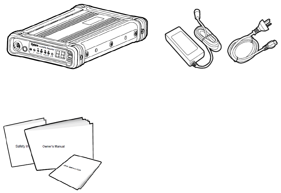
1. Checking Items in the Package
Please unpack carefully and check that all items listed below are received. If any item is missing or
damaged, please contact your local dealer.
Repeater Power Adapter
Documentation Kit
2
2. Product Overview
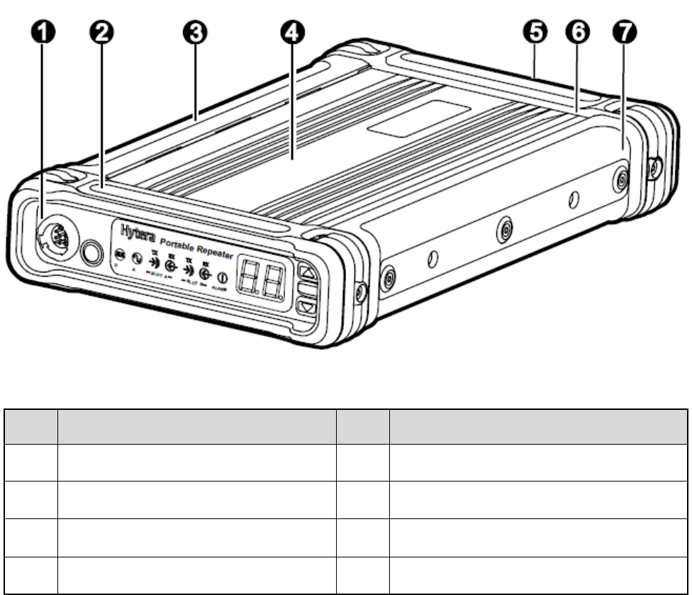
2.1 Parts
No. Part Name No. Part Name
1 Front Panel 2 Protective Cover of Front Panel
3 Left Protective Cover 4 Aluminum Chassis
5 Rear Panel 6 Protective Cover of Rear Panel
7 Right Protective Cover / /
3
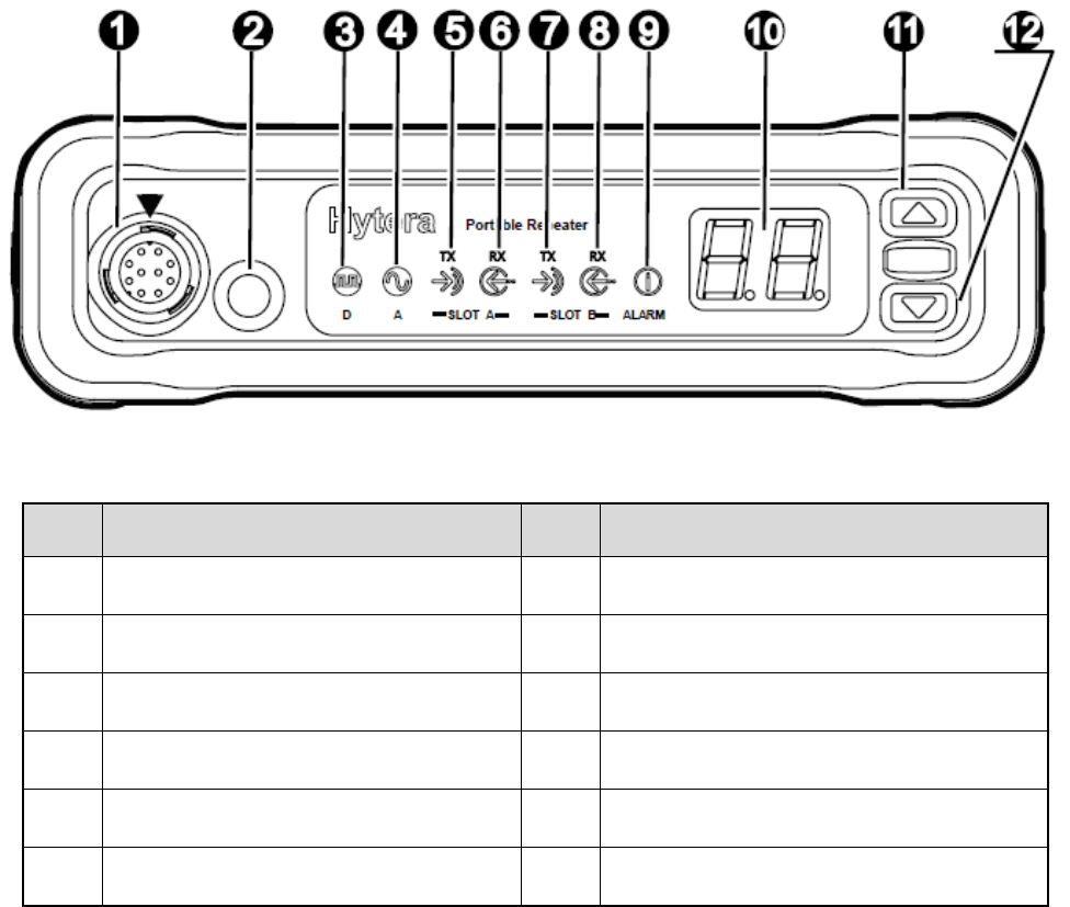
2.2 Front Panel
No. Part Name No. Part Name
1 Microphone Jack 7 Slot B Tx Indicator
2 Power On/Off Key 8 Slot B Rx Indicator
3 Digital Mode Indicator 9 Alarm Indicator
4 Analog Mode Indicator 10 LED Segment Display
5 Slot A Tx Indicator 11 Channel Up Key
6 Slot A Rx Indicator 12 Channel Down Key
4
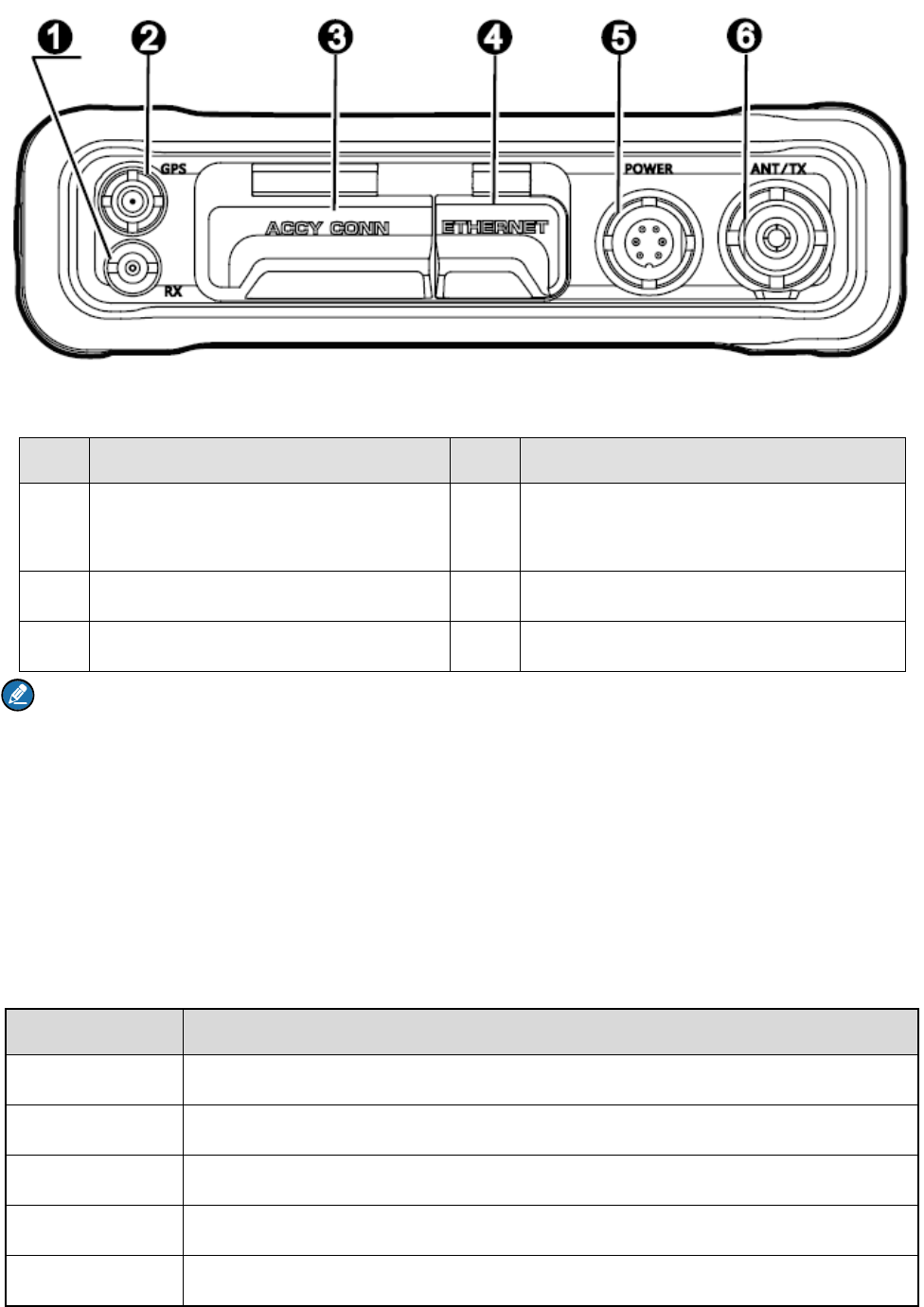
2.3 Rear Panel
No. Part Name No. Part Name
1 External Duplexer Jack/Rubber
Stopple 4 Ethernet Port
2 GPS Antenna Port 5 Power Inlet
3 Accessory Jack 6 Antenna Connector
Note: If the repeater is manufactured without internal duplexer, then part ① will be an external
duplexer port; if it is produced with internal duplexer, then part ① will be a rubber stopple.
2.4 Status Indication
2.4.1 LED Segment Display Indication
There will be different segments shown on the LED segment display. See their indications listed below:
LED Segment Repeater Status
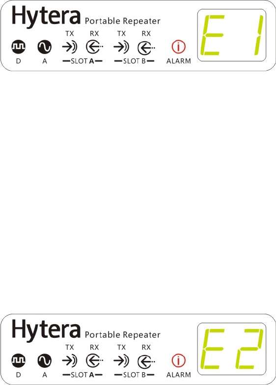
E1 Battery Mismatch
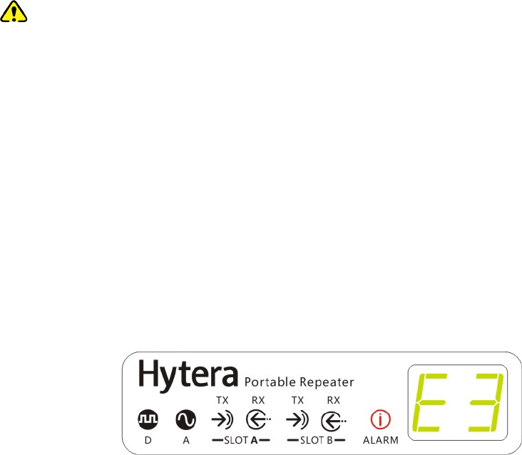
E2 Low Battery
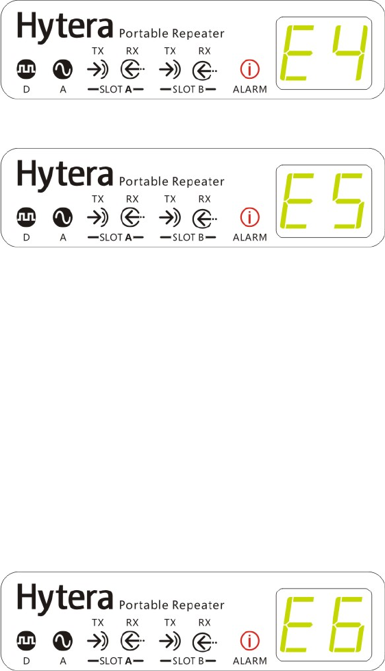
E3 External Power Abnormal
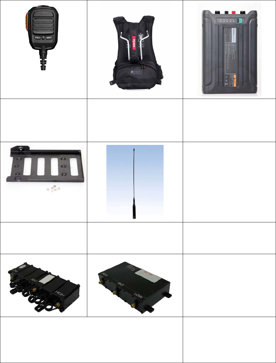
E4 Tx Unlock
E5 Rx Unlock

5
LED Segment Repeater Status
E6 Over Temperature
E7 VSWR Alarm
CHn Current Channel Number (e.g.: CH1, CH2, …CHn)
2.4.2 LED
Indicator LED Indication Repeater Status
Digital Mode Indicator Blue Working in Digital mode
Analog Mode Indicator Yellow Working in Analog mode
Slot A Tx Indicator Red
z Analog Mode: transmitting
z Digital Mode: Slot A transmitting
Slot A Rx Indicator Green
z Analog Mode: receiving
z Digital Mode: Slot A is receiving
Slot B Tx Indicator Red Digital Mode: Slot B transmitting
Slot B Rx Indicator Green Digital Mode: Slot B receiving
Alarm Indicator Red Abnormal operation and prompt pops up

6
3. Before Use
3.1 Instruction
Operation Environment
The repeater must be installed in a dry and well-ventilated place with ambient temperature of -30℃ –
+60℃ and relative humidity of not more than 95%.
Location
The repeater can be placed on the table or installed on the backpack with multi-functional brackets.
Voltage Check
Check whether the input voltage is within the operating voltage of the repeater (external power supply:
13.6V±15%; battery: 14.8V).
Note: To ensure the waterproof performance of the repeater, please do not disassemble it without
authorization. You can refer to Safety Information Booklet for more information.
3.2 Assembling Power Supply Management System (Optional)
If outdoor backpack power supply management system (model: PV3001, with internal battery) is needed,
ensure you’ve purchased it and the multi-functional bracket (model: BRK17). You can contact your
dealer for purchasing them.
3.2.1 Installation Tools
Tools required for installing the portable repeater include a cross head screwdriver and a T10 torx
screwdriver.
3.2.2 Assembling Steps
Step 1 Assemble the multi-functional bracket.
1. Place the repeater horizontally with its back (the side with the product information label)
upwards.
2. Put the multi-functional bracket horizontally on the back of the repeater as shown in the figure
below, and align the screw holes on the bracket to those of the repeater.
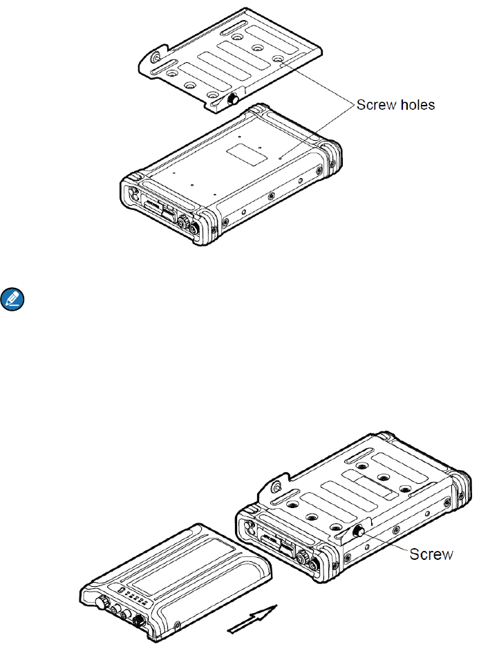
7
3. Secure the bracket with six M3*6 screws.
Note: Make sure the M3*6 screws are with spring washer to secure the screws before use.
Step 2 Assemble the power supply management system.
1. Push the power supply management system along the slots of the bracket slowly to the
bottom of the bracket, with the front of the system upwards. See the following figure.
2. Fasten the screws on the bracket to secure the system.
Step 3 Connect the system to the repeater with the power cord as shown in the following figure.
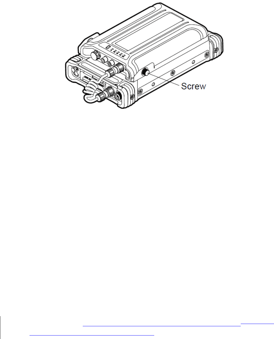
8
1. Plug the aviation plug (female) of the power cord into the power input of the repeater and
fasten the screws on the plug.
2. Plug the aviation plug (male) of the power cord into the power output of the system and fasten
the screws on the plug.
3.2.3 Product Check
Please check whether the repeater works properly by observing the seven LEDs and the LED segment
display located in the front panel.
3.3 Mounting the Products on the Backpack (Optional)
If you need to install the repeater and the power supply management system into the backpack
(NCN010), please make sure to purchase the backpack dedicated for this repeater. You can contact
your dealer for purchasing it.
The following steps show how to install the repeater and the power supply management system into the
backpack.
Step 1 Assemble the system on the repeater.
Please refer to “3.2 Assembling Power Supply Management System (Optional)Assembling
Power Supply Management System (Optional)” for detail operation.
Step 2 Connect the antenna (optional).
If you have purchased the antenna, please connect it to the antenna connector of the repeater.
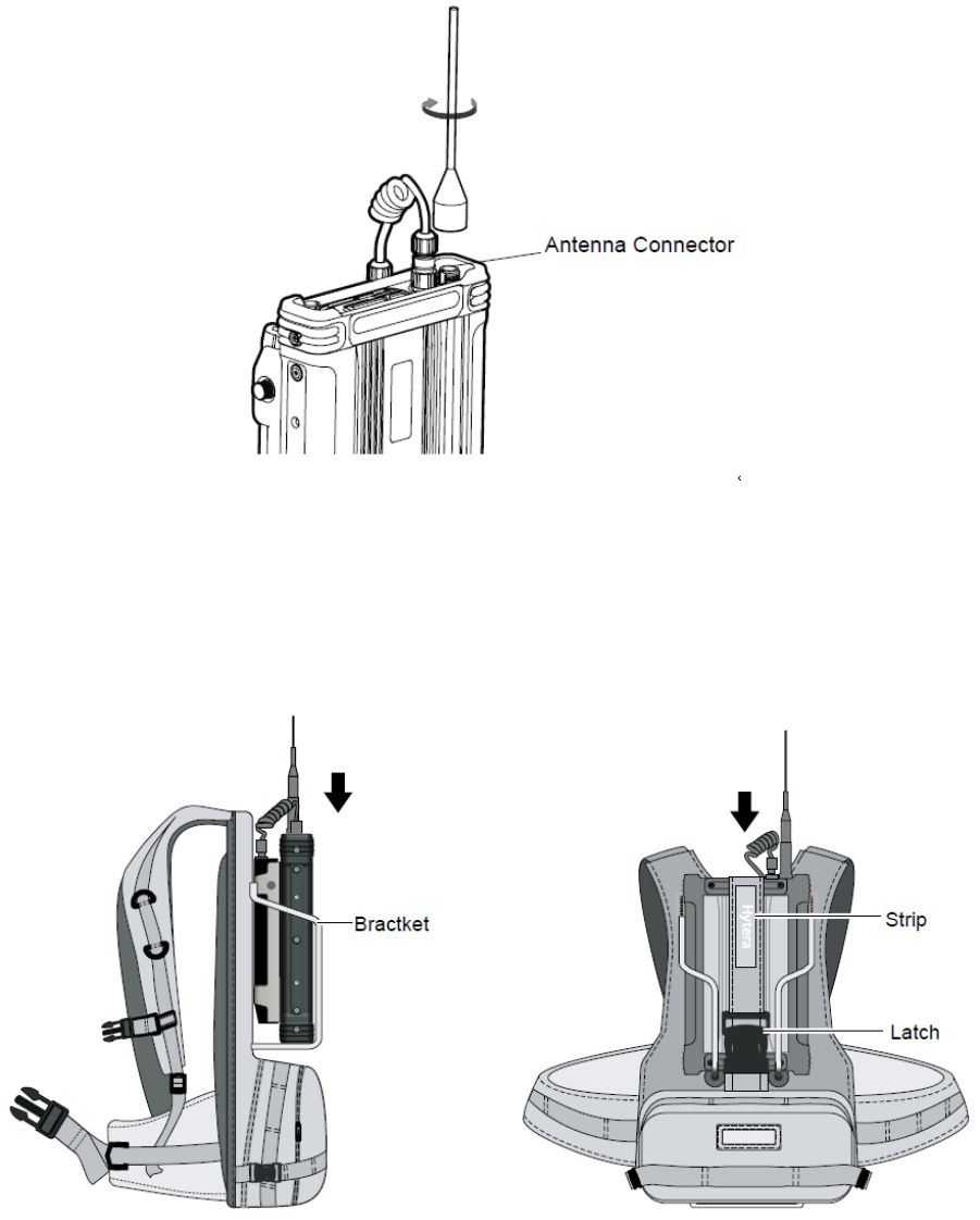
9
Step 3 Fix the repeater and the system into the backpack.
Insert the repeater and the power supply management system slowly into the bracket on the backpack
with the repeater outwards. Then adjust the strip of the backpack and latch it. See the following
figures:
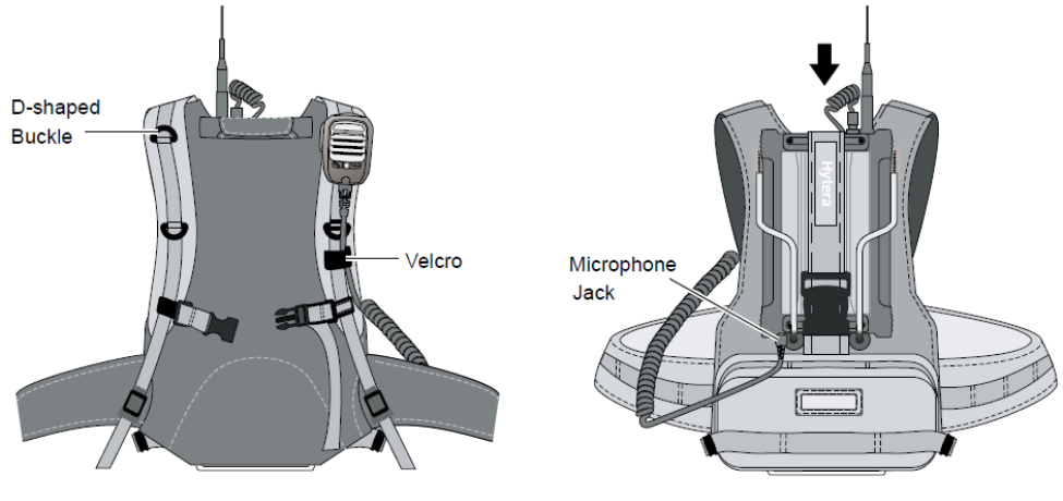
Step 4 Hang the remote speaker microphone (SM18A1) on the strap of the backpack (optional) as
shown in the following figure.
1. Hang the microphone on the D-shaped buckle on the strap.
2. Fasten the microphone wire by the Velcro.
3. Connect the microphone connector to the microphone jack of the repeater.
10

11
4. Basic Operations
4.1 Powering On/Off
Powering on/off manually
z To power on, long press the Power On/Off key for about 2s after connecting the power supply with the
power adapter.
z To power off, press the Power On/Off key.
Auto Power On
If the power of the adapter happens to be cut off or the power adapter runs out of the battery power when
in use, the repeater will be powered off forcibly. After that, when the power adapter restarts to supply
power, the repeater will power on automatically.
Note: The Auto Power on feature is set via the programming software by the dealer.
4.2 Adjusting the Power Level
You can request your dealer to set the Tx power to High or Low. High power can extend the repeater
coverage, enabling you to communicate with farther radios.
4.3 Changing the Channel
You can switch the channels by pressing the Channel Up/Down keys on the front panel. The Channel
Up key is for the former channel and the Channel Down key for the latter one. The alias of the current
channel is displayed on the LED segment display.
4.4 PTT Transmitting
If you have purchased the remote speaker microphone, you can press the PTT key on it to communicate
with other radios. Then the LED on the front panel will indicate the repeater status. Please refer to
“LEDLED”.
When the repeater is in a digital or mixed channel (“PTT Tx Channel Type” will be “Digital” then), if “Tx
Contact Name” is not defined, Slot A Tx Indicator will flash red rapidly when you press the PTT key.
Note: “PTT Tx Channel Type” and “Tx Contact Name” are set via the programming software by the
dealer.
带格
12
5. Alarm Information
The repeater will have real-time detection of its status automatically. If the relative alarms are enabled,
when the repeater is working improperly, the LED segment display will show the corresponding sign and
the alarm indicator on the front panel will glow red.
5.1 Battery Mismatch
When powered by a battery box, the repeater will examine whether the battery in the box matches its
requirements in a real-time way. When the battery does not match the requirement, the alarm indicator
will glow red and the LED segment display will show “E1”.
When this alarm is given, the repeater cannot work properly and will power off automatically in 3s. Then
please ask your local dealer to replace the power supply management system or for further help. If you
switch to an external power supply, this alarm will be eliminated with the segment disappearing and the
alarm indicator going out.
5.2 Low Battery
When powered by battery, the repeater will have real-time detection of the output voltage of the power
supply management system. When the output voltage falls below the under-voltage alarm threshold
(12% of the battery capacity by default), the alarm indicator will glow red and the LED segment display
will show “E2”.
When this alarm segment is displayed, the repeater will still work properly and will power off
automatically when running out of power.
In this case, you need to take the following measures:
1. Check the power indicator on the power supply management system to see if the power is low. If the
power is low, please charge the power supply management system or replace it.
13
Caution: After fully charging the system, please press the Power On/Off key to power on the
repeater, as it will not power on automatically.
2. If you cannot solve the problem, contact your local dealer for technical support.
When the battery voltage is higher than the under-voltage alarm threshold, the alarm will be eliminated
with the segment disappearing and the alarm indicator going out.
5.3 External Power Abnormal
When powered by a power adapter, the repeater will have real-time detection of the output voltage of the
power adapter. When the output voltage falls off the range of the operating voltage, the alarm indicator
will glow red and the LED segment display will show “E3”.
When this alarm is given, the repeater cannot work properly and will power off automatically in 3s. If the
repeater returns to normal operation within the 3s, the alarm will be eliminated so that the repeater will
not power off.
In this case, you need to take the following measures:
1. Check whether the power adapter is damaged. If it is damaged, please replace it.
2. Check through the voltmeter whether the voltage inputted by the external power supply is over low or
over high. If it is over low or over high, please replace it.
3. If you cannot solve the problem, contact your local dealer for technical support.
5.4 TX/RX Unlock
Normally, after being powered on, the repeater has its Tx and Rx work properly in locked status. Once
the repeater detects that the Tx/Rx PLL is unlocked, its alarm indicator will glow red and there will be a
sign (“E4” for Tx Unlock, “E5” for Rx Unlock) on the LED segment display.
14
Tx Unlock Alarm
Rx Unlock Alarm
When such alarm is given, the repeater will terminate part of its features automatically. Now you will
need to contact your local dealer for technical support.
When Tx/Rx returns to the locked status, the alarm will be eliminated with the segment disappearing and
the alarm indicator going out.
5.5 Over Temperature
When the temperature of the PA module exceeds the normal range, the alarm indicator will glow red and
the LED segment display will show “E6”.
When this alarm is given, the repeater can still work properly. During a rise in ambient temperature, the
repeater will keep track of the Tx power with adjustments in order to lower the temperature.
And you need to take the following measures:
1. Check whether the ambient temperature and ventilation conditions of the repeater satisfy the
foregoing installation requirements. If not, please make improvements as soon as possible.
2. Check if connection between the transmitter and RF cable or antenna/feed line is loose or damaged.
Poor connection between them could cause high Tx power, which would make the temperature of the
heat sink rise quickly. If yes, secure or replace the cable or antenna/feed line.
3. If the above measures fail to solve the problem, contact your local dealer for technical support.
When the temperature of the repeater returns to the normal range, the alarm will be eliminated with the

15
segment disappearing and the alarm indicator going out.
5.6 VSWR Alarm
When transmitting, the repeater will detect the voltage standing wave ratio (VSWR) of the Tx antenna of
the PA module. Over-high VSWR will damage the PA module or even disable it. When the VSWR
exceeds the normal range, the alarm indicator will glow red and the LED segment display will show “E7”:
When this alarm is given, the repeater can still work properly.
And you need to take the following measures:
1. Check if the Tx frequency is within the frequency range of the antenna, as improper antenna will result
in poor transmitting performance or even damage to the transmitter. If not, please contact your local
dealer to replace the antenna.
2. Check if the connection between the transmitter and RF adapter cable or antenna/feed line is loose or
damaged. If yes, please replace the cable.
3. If you cannot solve the problem, contact your local dealer for technical support.
When the VSWR returns to the operation range, the alarm will be eliminated with the segment
disappearing and the alarm indicator going out.

16
6. Troubleshooting
Phenomena Analysis Solution
Power-on failure
The power cord may be
unconnected or not securely
connected to the outlet.
Properly connect the power cord and
ensure secure connection.
The fuse in the power cord may
be damaged. Please replace the fuse.
The battery may have low power
when supplying.
Please charge the battery or contact the
dealer to replace the power supply
management system.
The power adapter may output
improper voltage.
Check if the power adapter outputs the
voltage within the required range (13.6V±
15%). If not, replace the power adapter.
Group members
cannot talk to each
other, or the
repeater cannot
communicate with
a radio.
Tx/Rx frequency of the repeater is
inconsistent with that of
portable/mobile radios.
Check if the Tx/Rx frequencies are
consistent with each other, and re-set the
frequencies if necessary.
Failed to repeat useful signal due
to strong interference signal.
If you cannot remove or bypass the
interference source, change to operate at
other frequencies.
The group member is out of the
coverage of the repeater. Go within the coverage of the repeater.
Group members
cannot talk to each
other, even though
Rx indication is
given.
The radio ID is inconsistent with
that of the other group members.
Set the subscriber ID to the same as that
of the other members.
Inconsistent CTCSS/CDCSS. Re-set CTCSS/CDCSS.
Short
communication
range or poor
audio.
The connection cable is damaged,
and the signal energy leaks.
Replace the cable with a new one if
necessary.
The antenna connector and the
cable may get loose connection or
even disconnected.
Secure the cable connector, or replace it if
necessary.

17
Phenomena Analysis Solution
Invisible damage may occur to the
cable. Replace the cable with a new one.
Duplexer is not properly set (if the
duplexer is mounted).
Contact the manufacturer or your dealer to
re-set the duplexer.
If the above solutions can not fix the problems for you, or you may have some other queries, please
contact us or your local dealer for more technical support.

18
7. Care and Cleaning
To guarantee optimal performance as well as a long service life of the product, please follow the tips
below.
Product Care
z Keep the product at a place of good ventilation and heat dissipation to facilitate normal work.
z Do not place irrelevant articles on top of the product to ensure optimal heat dissipation.
z Do not pierce or scrape the product.
z Keep the product far away from substances that can corrode the circuit.
z Do not place the product in corrosive agents, solutions or water.
Product Cleaning
Caution: Be sure to power off the product before cleaning.
z Remove the dust and fine particles on the repeater surface with a clean and dry lint-free cloth or a
brush regularly.
z Use a non-woven fabric with neutral cleanser to clean the keys, control knobs, LCD and jacks after
long-time use. Do not use chemical preparations such as stain removers, alcohol, sprays or oil
preparations. Make sure the product is completely dry before use.
19
8. Optional Accessories
The following items are the main optional accessories for the repeater, and please consult your local
dealer for more information of other accessories.
Remote Speaker Microphone
SM18A1
Backpack
NCN010
Outdoor Backpack Power Supply
Management System PV3001
(Internal Battery: BL9901)
Multi-functional Bracket
BRK17
Vehicle Antenna
/
Duplexer (Frequency: 136-174MHz; RX-TX spacing: 5MHz) DT11
Duplexer (Frequency: 350-400MHz; RX-TX spacing: 10MHz) DT12
Duplexer (Frequency: 400-470MHz; RX-TX spacing: 10MHz) DT13
/

20
Caution: Use the accessories specified by the Company only. If not, Hytera shall not be liable for
any loss or damage arising out of use of unauthorized accessories.