Hytera Communications RD98XSV3 DIGITAL REPEATER User Manual RD98XS Owner s Manual 100202
Hytera Communications Corporation Limited DIGITAL REPEATER RD98XS Owner s Manual 100202
User manual
Preface
Thank you for purchasing Hytera RD98XS series DMR digital repeater.
As a product built to the DMR standard, RD98XS is endowed with ergonomic design,
reliable performance and comprehensive digital functions to deliver an advanced
communication solution. With RD98XS, you can make use of digital advantages to top the
competition!
To ensure you get maximum benefit from the product, please read this manual carefully
before use.

1
Icon Information
The following icons are available through this manual:
Caution: indicates situations that could cause damage to your repeater or bodily
injury.
Note: indicates tips that can help you make better use of your repeater.
* Indicates functions or parts that are not supported by the current version of the repeater,
but will be available to future versions.
Copyright Information
Hytera and HYT are the trademark or registered trademark of Hytera Communications
Co., Ltd in PRC and other countries and/or areas. Hytera retains the ownership of its
trademarks and product names. All other trademarks and/or product names that may be
used in this manual are properties of their respective owners.
The Hytera product described in this manual may include Hytera computer programs
stored in memory or other media. Laws in the PRC and/or other countries or areas
preserve for Hytera exclusive rights for Hytera computer programs. The purchase of this
product shall not be deemed to grant, either directly or by implication, any rights to the
purchaser with respect to Hytera computer programs. Any Hytera computer programs
may not be copied, modified, distributed, decompiled, or reverse-engineered in any
manner without the prior written consent of Hytera.
Disclaimer
Hytera endeavors to achieve the accuracy and completeness of this manual, but no
warranty of accuracy or reliability is given. All the specifications and designs are subject to
change without prior notice due to continuous technology development. No part of this
manual may be copied, modified, translated, or distributed in any manner without the
express written permission of Hytera.
If you have any suggestions or would like to learn more details, please visit us at:
http://www.hytera.cn.
2
Contents
Checking Items in the Package......................................................................................... 3
Repeater Overview ........................................................................................................... 4
Front Panel ................................................................................................................ 4
Rear Panel................................................................................................................. 5
Internal Parts.............................................................................................................. 6
Installation......................................................................................................................... 6
Installation Overview.................................................................................................. 7
Before Installation ...................................................................................................... 7
Installation Requirements........................................................................................... 8
Installation Steps...................................................................................................... 10
Electrical Connections..................................................................................................... 13
Power Supply Connections...................................................................................... 13
RF Antenna Connections ......................................................................................... 14
Post-Installation Checklist ............................................................................................... 15
Status Indications ............................................................................................................ 16
LCD Icons ................................................................................................................ 16
LED Indicator ........................................................................................................... 16
Basic Operations............................................................................................................. 17
Turning the Repeater On/Off.................................................................................... 17
Adjusting the Volume ............................................................................................... 17
Adjusting Power Level ............................................................................................. 18
Backlight .................................................................................................................. 18
Locking/Unlocking the Front Panel .......................................................................... 18
Menu Navigation ............................................................................................................. 19
Radio Info ................................................................................................................ 19
Channel Info............................................................................................................. 20
Exit........................................................................................................................... 20
Alarm Information............................................................................................................ 20
Over Temperature Alarm .......................................................................................... 21
Fan Failure Alarm..................................................................................................... 21
VSWR Alarm............................................................................................................ 22
Low Forward Power Alarm....................................................................................... 23
Over/Low Voltage Alarm .......................................................................................... 23
Troubleshooting .............................................................................................................. 25
Care and Cleaning .......................................................................................................... 26
Optional Accessories....................................................................................................... 27
3
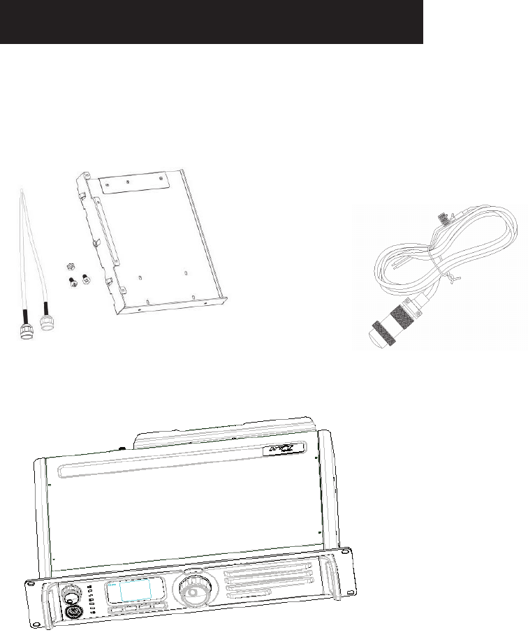
Checking Items in the Package
Please unpack carefully and check that all items listed below are received. If any item is
missing or damaged, please contact your dealer.
Duplexer Installation Kit Power Cord
Repeater
Owner’s Manual
4
Repeater Overview
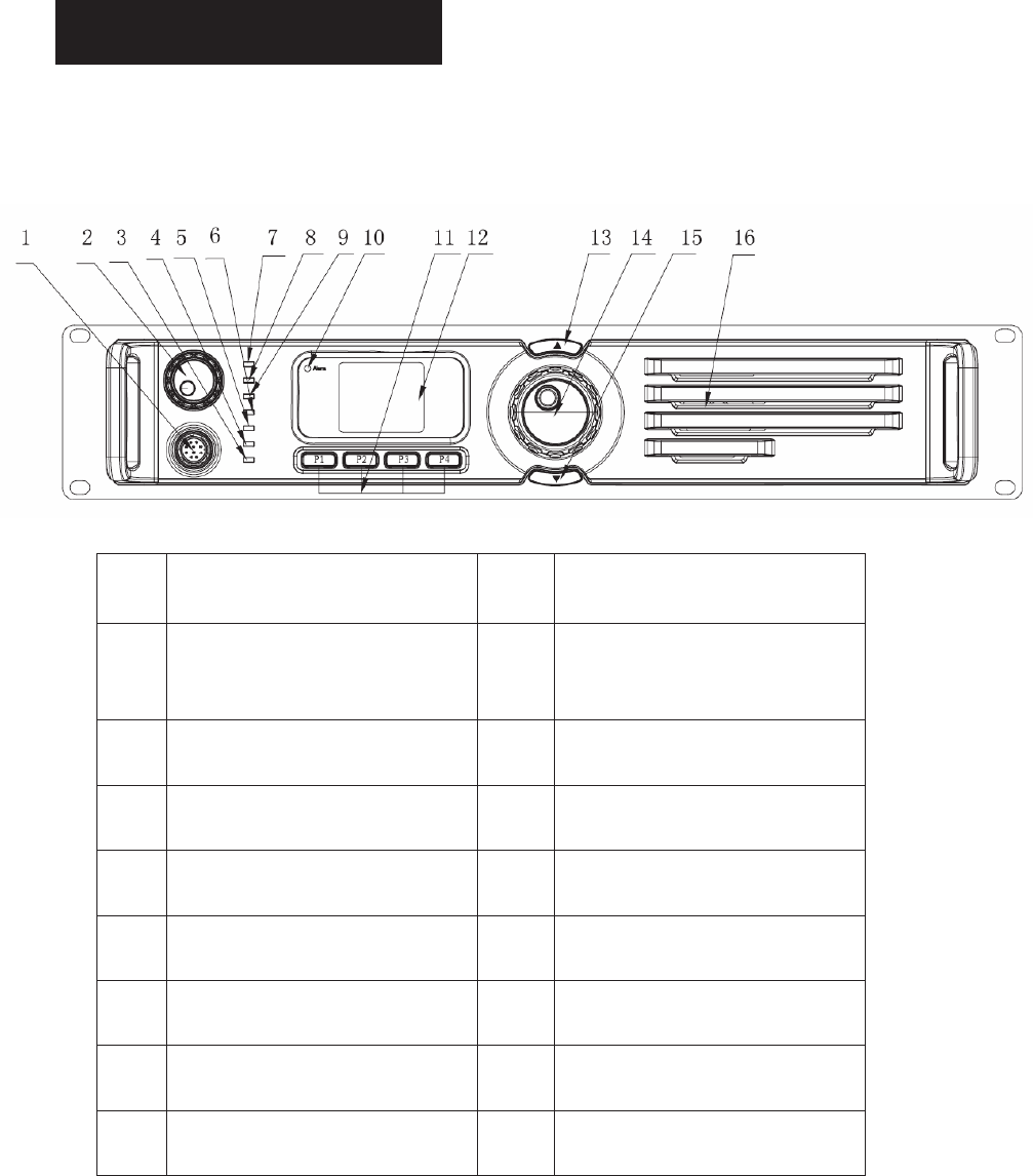
Front Panel
No. Part Name No. Part Name
ƻ
1Accessory Jack ƻ
2
Volume Control Knob / Power
Indicator
ƻ
3Repeater Mode Indicator ƻ
4Analog Mode Indicator
ƻ
5Slot 2 RX Indicator ƻ
6Slot 2 TX Indicator
ƻ
7 Digital Mode Indicator ƻ
8 Slot 1 TX Indicator
ƻ
9 Slot 1 RX Indicator ƻ
10 Alarm Indicator
ƻ
11 Programmable Keys ƻ
12 LCD Display
ƻ
13 Channel Up Key ƻ
14 Menu Navigation Knob
ƻ
Channel Down Key ƻ
16 Speaker
5
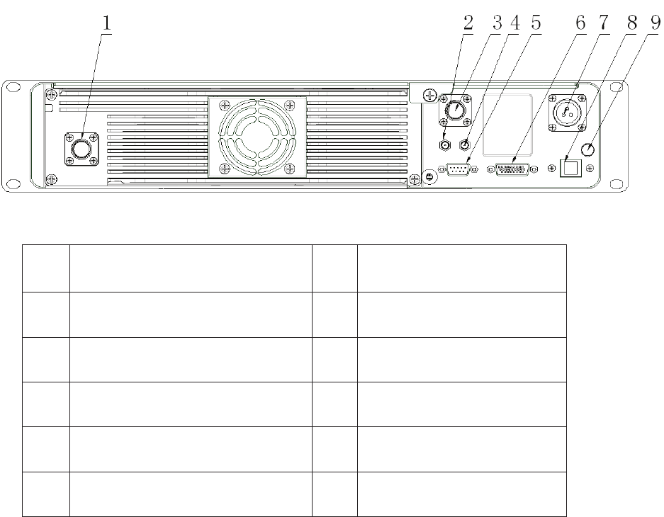
Rear Panel
No. Part Name No. Part Name
ƻ
1TX Antenna Connector ƻ
2Optional Connector 1
ƻ
3RX/Duplex Antenna Connector ƻ
4Optional Connector 2
ƻ
5 Monitor/Test Jack ƻ
6 Accessory Jack
ƻ
7 DC Power Inlet ƻ
8 Ethernet Port
ƻ
9 Ground Screw
6
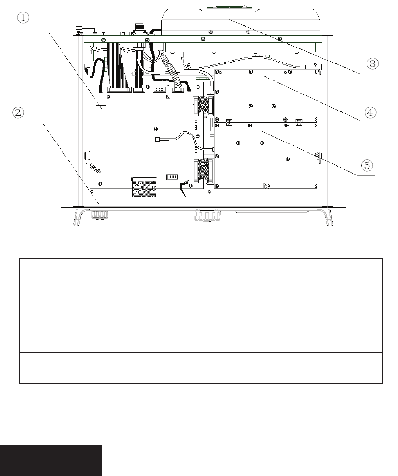
Internal Parts
No. Part Name No. Part Name
ƻ
1Baseband Module ƻ
2Front Panel
ƻ
3RF PA Module ƻ
4Excitor Module
ƻ
5 RX Module
Installation
Proper installation can ensure optimum performance and reliability of the repeater. Be
sure to read the following installation requirements and instructions carefully, before you
install the repeater.

7
Installation Overview
The information below is an overview for installing the repeater and auxiliary equipment.
Unpack and inspect the equipment.
Perform a pre-installation function check test of the equipment, and configure
parameters.
Pay particular attention to environmental conditions at the site, ventilation
requirements, and grounding and lightning protection.
Install the equipment at the site.
Make necessary electrical and cabling connections, including the following:
- DC power cord
- Coaxial cables to TX and RX antennas (if you use two antennas)
Perform a post-installation function check test of the equipment, to verify proper
installation.
Before Installation
Before you install the repeater at the site, you are suggested to power on the repeater and
check it for proper operation.
1. Applying Power
Before applying power to the repeater, make sure the voltage of DC power supply or
battery is compliant with the operating voltage range of the repeater. Then connect the DC
power supply or battery to supply power to the repeater.
2. Verifying Proper Operation
Operation of the repeater can be indicated by the 8 LEDs located on the front panel. After
proper operation is verified, you can configure parameters for the repeater.
Caution: Some repeater components can become extremely hot during operation.
Turn off all power and wait until the repeater is sufficiently cool before touching the
repeater.
3. Configuring Parameters

8
You may customize repeater parameters such as TX/RX frequency, TX power and
signalling, according to user needs. After configuration of parameters is complete, you
may perform site installation.
Installation Requirements
1. Environmental Conditions at Intended Installation Site
The repeater may be installed in any location suitable for electronic communication
equipment, provided that the environmental conditions do not exceed the equipment
specifications for temperature, humidity and air quality.
Operating Temperature
-30ć to +60ć
This is the temperature measured in close proximity to the repeater. For example, if the
repeater is mounted in a cabinet, the temperature within the cabinet is measured.
Humidity
Humidity conditions should not exceed 95% relative humidity @ 50°C.
Air Quality
For equipment operating in an area which is environmentally controlled and with the
repeater rack mounted, the airborne particle level must not exceed 25ȝg/m3.
And for equipment operating in an area which is not environmentally controlled and with
the repeater cabinet mounted, the airborne particle level must not exceed 90ȝg/m3.
Caution: If the repeater is to be installed in an area which is usually dusty, dirty, or
does not meet the air quality requirements, then the air used to cool the repeater modules
must be treated using appropriate filtering devices. Dust or dirt accumulated on the
internal circuit boards and modules is not easily removed, and can cause malfunctions
such as overheating and intermittent electrical connections.
2. Equipment Ventilation
The PA heatsink is equipped with a cooling fan used to provide forced convection cooling.
When planning the installation, observe the following ventilation guidelines:
Customer supplied cabinets must be equipped with ventilation slots or openings for

9
air to enter and exit. If several repeaters are installed in a single cabinet, ensure
ventilation openings surrounding each repeater allow for adequate cooling.
All cabinets must have at least 10cm of open space between the air vents and any
wall or other objects.
When multiple cabinets (each equipped with several repeaters) are installed in an
enclosed area, ensure appropriate ventilation and consider air conditioning or other
climate control equipment, to satisfy the temperature requirements stated above.
3. Equipment Installation Methods
The RD980 repeater may be mounted in a rack, bracket or cabinet, and may be placed on
your desk.
4. Site Grounding and Lightning Protection
Caution: Proper site grounding and lightning protection are vitally important
considerations. Failure to provide proper lightning protection may result in permanent
damage to the repeater.
The ground and lightning protection system is one of the most important considerations
when designing a communication site. Proper grounding techniques and lightning
protection are closely related, and the general category of site grounding may be divided
into the following two sections:
Electrical Ground
Ground wires carrying electrical current from circuitry or equipment at the site are included
in the category of electrical ground. Examples include the AC and DC power used to
source equipment located at the site, and wires or cables connected to alarms or sensors
located at the site.
Lightning Ground
Providing adequate lightning protection is critical to a safe reliable communication site.
The repeater is equipped with a ground screw located on the rear panel. This screw is
used to connect the repeater to the site grounding. All antenna cables, and AC and DC
power cords, should be properly grounded and lightning protected by following the rules
and guidelines provided in the above sections.
10
Installation Steps
You will need a Philips screwdriver (cross head screwdriver), a Torx (T10) screwdriver and
a spanner, to install the repeater.
Caution: Be sure to observe proper electrostatic discharge precautions if any part
must be removed from the repeater.
The installation steps are as follows:
1. Mount the repeater in a rack, bracket or cabinet.
2. Connect accessories such as antenna cables and power cords to the repeater.
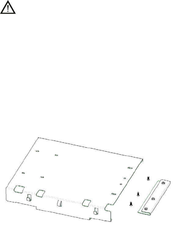
If a duplexer needs to be mounted
If the repeater needs to work with a duplexer, your will need to implement the following
installation steps prior to the above steps 1 and 2.
1. Loosen the three screws on the bracket with a Philips screwdriver.
2. Install the optional duplexer and the bracket. Be sure to observe the specifications of
the two antenna connectors on the duplexer, to determine which connector should be
connected to the transmitter. Ensure the antenna connector connected to the
transmitter is beside the rear panel of the repeater.
Take Hytera supplied duplexer as an example. If the transmitter is connected to the
low cavity connector, the duplexer should be mounted with the front side facing
upwards (see the following figure on the left); and if it is connected to the high cavity
connector, the duplexer should be mounted with the front side facing downwards (see
the following figure on the right).
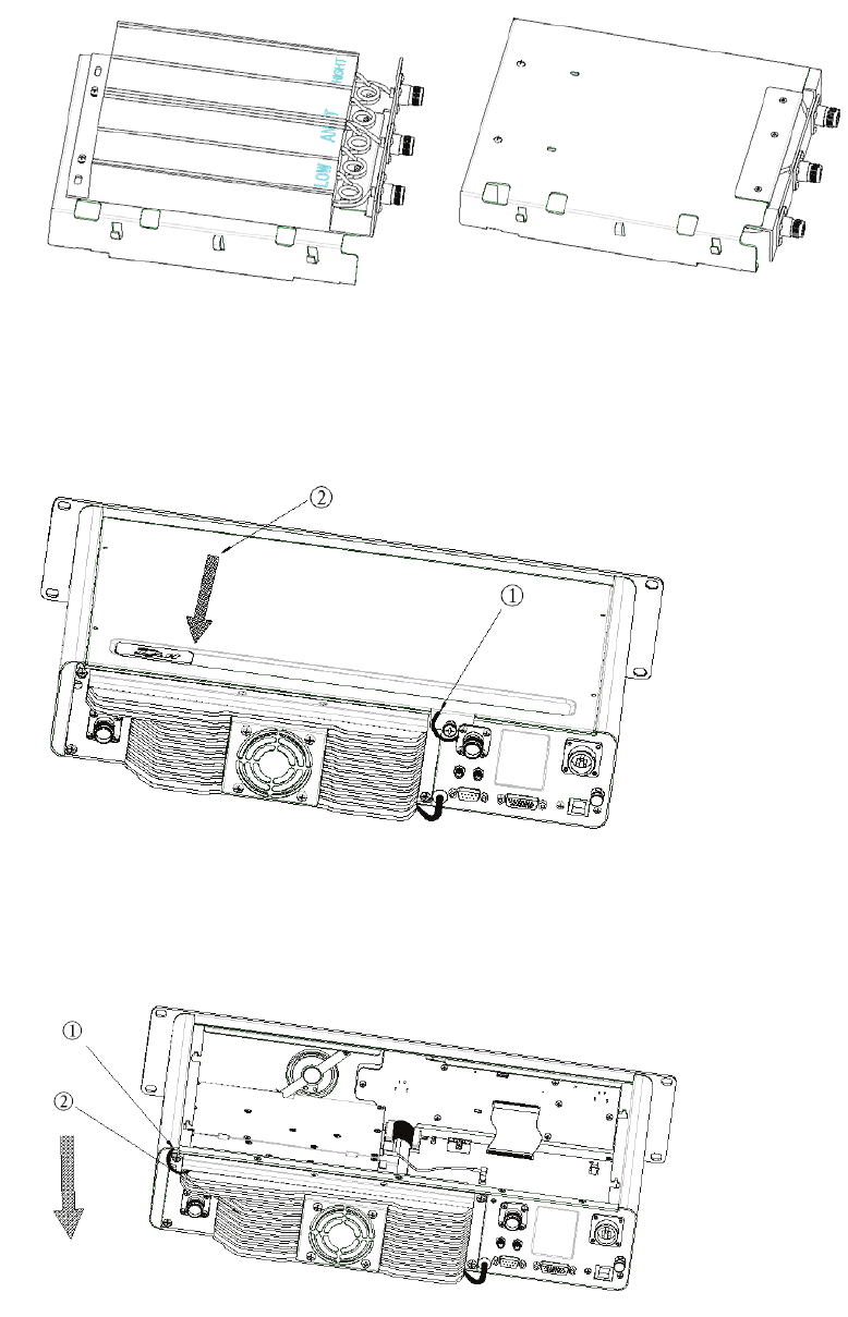
11
3. Loosen the screw at the back of the top cover, and then pull the top cover to remove
it.
4. Loosen the 6 screws locking the PA heatsink, remove all power, data and RF cables
from the PA, and finally remove the PA heatsink.
5. Mount the duplexer, and fasten the 2 screws inside the housing and on the side panel
respectively. Then mount the PA heatsink, and connect all the lines and cables.
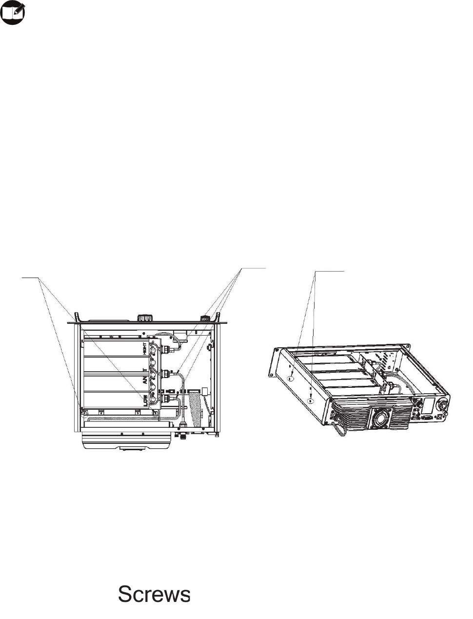
12
Ensure RF cables are properly connected between the duplexer and RF
connectors.
TX signal:
Excitor module -> PA module -> Duplexer TX connector -> Duplexer antenna connector ->
RX/duplex antenna connector (rear panel)
RX signal:
RX/duplex antenna connector (rear panel) -> Duplexer antenna connector -> Duplexer RX
connector -> RX module
Diagrams of Assembled Unit
Duplexer Mounted with Front Side Facing Upwards
13
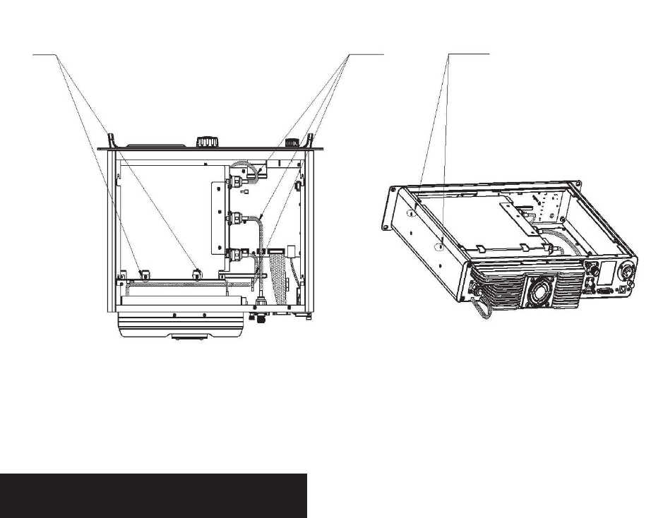
Screws RF cables Screws
Duplexer Mounted with Front Side Facing Downwards
Electrical Connections
After the repeater has been mechanically installed, electrical connections must be made.
This involves making the following connections:
z DC power cord
z Antenna cables
See the rear panel view for the positions of connectors.
Power Supply Connections
1. Ground Connection
The repeater is equipped with a ground screw located on the rear panel. Connect ground
wires to the screw.
2. DC Power Supply or Battery Backup Connection

14
The repeater may be connected to a regulated DC power supply or a backup battery.
The DC source or battery backup system is connected to the repeater through the DC
power inlet at the rear of the repeater (see rear panel view).
Caution: Before you make the connection, ensure the DC power supply or battery
backup system is capable of supplying a minimum of 200W, and check if the DC power
supply has current limit. Since high current consumption is required for transmitting,
improper setting of the current limit may cause transmission failure.
Caution: The repeater is to be connected to a battery that is in accordance with
applicable electrical regulations for the end use country. If battery power is exhausted, you
are recommended to charge the battery with an external charger. Remove the battery
from the repeater when charging.
RF Antenna Connections
TX and RX antennas are connected to two separate connectors (shown in the rear panel
view), and there must be adequate isolation of 75 dB UHF or 85 dB VHF between them. If
only one antenna through a duplexer is connected, at least 75 dB UHF or 85 dB VHF
isolation between the TX and RX antenna ports is required.
Caution: Please ensure that all power is switched off before disconnecting the TX
antenna.
1. Duplexer Selection
The selection of duplexer is critical to system performance. The use of a notch (band
reject) duplexer is possible in some systems that are not located at high RF density sites.
If the repeater is used in high RF density sites, the use of a pass-notch duplexer is
recommended.
The duplexer must be able to handle at least 50W continuously. For the best system
performance, the insertion loss should be less than 2dB.

15
2. Antenna Selection
The selection of antenna is also critical to system performance. The selected antenna
must be 50 Ohm impedance and capable of at least 50W. High gain antennas may be
used to increase system coverage. Please take note of licensing restrictions when
selecting high gain antennas. Some services or regions may have antenna gain or system
radiation limitations.
The antenna must be connected to the duplexer with a high grade 50 Ohm transmission
line (e.g. Andrew HELIAX cables). The line must have connectors to match the
connectors on the duplexer and antenna.
Caution: It is important that all antenna cables are grounded at the point they enter
the building. All aspects of the antenna design must comply with the relevant local
regulations.
Post-Installation Checklist
After the repeater has been mechanically installed and all electrical connections have
been made, power may now be applied and the repeater should be checked for proper
operation.
1. Applying Power
Before applying power to the repeater, make sure all boards are securely seated in the
appropriate connectors on the rear panel and all RF cables are securely connected.
Turn on the DC power source to supply power to the repeater.
2. Verifying Proper Operation
Operation of the repeater can be indicated by the 8 LEDs located on the front panel and
also by LCD prompts.
Caution: Some repeater components can become extremely hot during operation.
Turn off all power and wait until the repeater is sufficiently cool before touching the
repeater.
16
Status Indications
LCD Icons
The LCD of your repeater displays the repeater status and menu items. The following are
the icons that appear on the display.
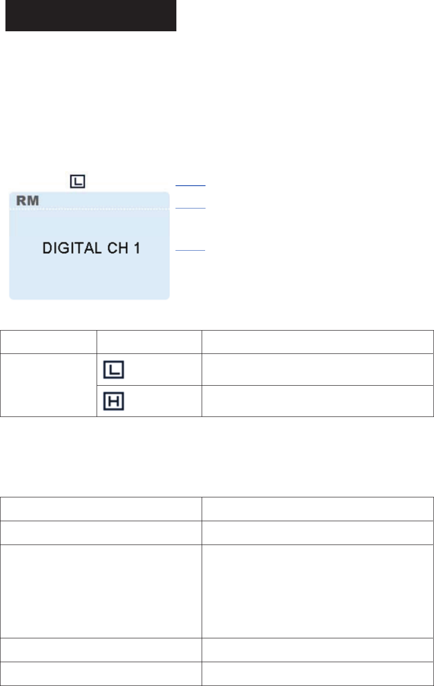
Standby Screen
Status Icon (Tx power)
Repeater Mode
Channel Alias (programmable
by dealer)
Status Icons
Icon Name Icon Repeater Status
Low TX power for the current channel
Transmit Power
Icons High TX power for the current channel
LED Indicator
LED Indicator Repeater Status
Power Indicator glows green Repeater being turned on
Alarm Indicator glows red
Repeater giving an alarm due to failure of some
component (please observe the LCD prompt,
and carry out troubleshooting as the “Alarm
Information” section instructed.)
Repeater Mode Indicator glows green Repeater operating in Repeater Mode (RM)
Repeater Mode Indicator is not lit Repeater operating in Repeater Base Mode

1
7
(RBM)
Slot 1 TX Indicator glows red
Repeater transmitting (analog) / repeater
transmitting on slot 1 (digital)
Slot 1 TX Indicator flashes red Busy channel lockout / transmission time-out
Slot 2 TX Indicator glows red Repeater transmitting on slot 2 (digital)
Slot 2 TX Indicator flashes red Busy channel lockout / transmission time-out
Slot 1 RX Indicator glows green Repeater receiving (analog) / repeater receiving
on slot 1 (digital)
Slot 1 RX Indicator flashes green Monitoring
Slot 2 RX Indicator glows green Repeater receiving on slot 2 (digital)
Analog Mode Indicator glows yellow Repeater operating in analog mode
Digital Mode Indicator glows blue Repeater operating in digital mode
Basic Operations
Turning the Repeater On/Off
Connect the repeater to a DC source to turn the repeater on. At this time, the Power
Indicator glows green and the repeater shows the power-up screen.
To turn the repeater off, disconnect it from the DC source.
Adjusting the Volume
When the repeater operates in analog mode, rotate the Volume Control knob clockwise
to increase the volume of speaker output audio, or counter-clockwise to decrease the
volume.
When the repeater operates in digital mode, the speaker cannot output audio, and no

18
volume adjustment through the knob is available.
Adjusting Power Level
You may request your dealer to set the TX power to high or low.
The LCD displays icon for high power, and icon for low power. High power
can optimize coverage of the repeater, to communicate with farther terminals.
Backlight
In insufficient light conditions, activating the backlight can illuminate the LCD and all the
front panel keys, facilitating user operation.
You dealer may set the backlight to operate in any of the following modes:
Timed: any key or knob operation or receiving/transmitting of signals can illuminate
the backlight. If none of the above operations is made within the specified time period,
the backlight will go out automatically.
Enable: Since the repeater is powered on, the backlight will remain illuminated all the
time.
Disable: The backlight will always remain disabled.
Note: When an alarm indication occurs, the backlight will remain illuminated until the
alarm disappears. Then it will recover the initial operation mode.
Locking/Unlocking the Front Panel
Your dealer may lock all the front panel keys and knobs, to prevent accidental operation.
Note: To unlock the front panel, the repeater must be re-programmed by your dealer.
19
Menu Navigation
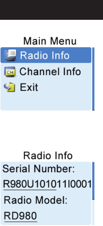
Radio Info
Under this menu, you can view the basic information of your repeater, including serial
number, radio model, frequency range, firmware version and etc.
To access this menu:
1. In the home screen, press the Menu Navigation knob to enter the main menu.
2. Rotate the knob to select the "Radio Info” option.
3. Press the knob again to view basic information of the repeater.
Then you may rotate the knob to scroll up/down. To exit, just press the knob.

20
Channel Info
Under this menu, you can view some information of the current channel, including channel
alias, TX/RX frequency, channel spacing (analog only), TX/RX CTCSS/CDCSS (analog
only), color code (digital only) and etc.
To access this menu:
1. In the home screen, press the Menu Navigation knob to enter the main menu.
2. Rotate the knob to select the "Channel Info” option.
3. Press the knob again to view information of the current channel.
Then you may rotate the knob to scroll up/down. To exit, just press the knob.
Exit
To exit from the main menu, rotate the Menu Navigation knob to select the "Exit” option,
and then press the knob.
Alarm Information
The repeater can automatically detect its operation status in real time, such as PA
over-temperature, low forward power, high VSWR, high/low voltage and fan failure. When
any of the above occurs, the LCD will give you a prompt, and the Alarm Indicator will glow
red.
21
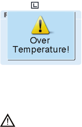
Over Temperature Alarm
When temperature of the PA module exceeds the normal range, the Alarm Indicator will
glow red and the LCD will display the prompt below:
Then the repeater will disallow transmission, and you will need to:
1. Check if the surface temperature of PA heatsink exceeds 80ć. If yes, implement the
following steps 2 and 3 to locate the failure.
Caution: The PA heatsink can become extremely hot at this moment, so DO NOT
touch the repeater. Use a digital thermometer with thermocouple to measure temperature.
2. Check if ambient temperature and equipment ventilation can satisfy the foregoing site
installation requirements. If not, please improve environmental conditions at the site
as soon as possible, by mounting air conditioning equipment or improving equipment
ventilation.
3. Check if connection between the transmitter and RF or antenna cables is loose or lost.
If yes, please secure the connection or replace the cables. Poor connection between
them could result in very high TX power and thus high temperature of PA heatsink.
4. If you are unable to verify the above conditions, please contact your local dealer for
technical support.
When temperature of the repeater drops into the normal operating range, the LCD prompt
will disappear, and the Alarm Indicator will go out.
Fan Failure Alarm
When the fan fails to work, the Alarm Indicator will glow red and the LCD will display the
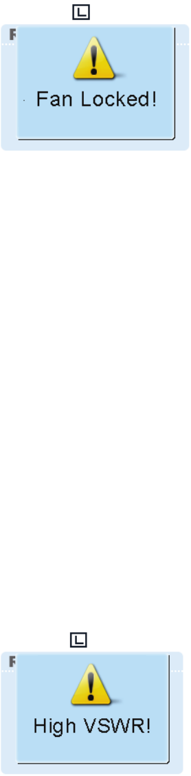
22
prompt below:
Then the repeater will automatically switch to low TX power, to protect the transmitter from
overheating.
You will need to:
1. Check if the fan is blocked by any solid object. If yes, please remove it.
2. If you cannot solve the issue, please contact your local dealer for technical support.
When the fan recovers normal operation, the LCD prompt will disappear, and the Alarm
Indicator will go out.
VSWR Alarm
High VSWR (voltage standing wave ratio) at the TX antenna connector will result in
damage to the PA, and even failure of the transmitter.
When the VSWR exceeds the normal range, the Alarm Indicator will glow red and the LCD
will display the prompt below:
Then the repeater will automatically switch to low TX power.
You will need to:
1. Check if the TX frequency is within the frequency range of the antenna. If not, please
contact your local dealer to replace the antenna. Improper antenna selection could

23
result in poor transmitting performance, and even damage to the transmitter.
2. Check if connection between the transmitter and RF or antenna cables is loose or lost.
If yes, please secure the connection or replace the cables.
3. If you cannot solve the issue, please contact your local dealer for technical support.
When the VSWR falls within the normal range, the LCD prompt will disappear, and the
Alarm Indicator will go out.
Low Forward Power Alarm
When the forward power is below the preset value, the Alarm Indicator will glow red and
the LCD will display the prompt below:
Then the repeater may continue transmission or may terminate it, subject to repeater
status currently detected.
You will need to:
1. Check if connection between the transmitter and RF or antenna cables is loose or lost.
If yes, please secure the connection or replace the cables.
2. If you cannot solve the issue, please contact your local dealer for technical support.
When the forward power is recovered to its normal value, the LCD prompt will disappear,
and the Alarm Indicator will go out.
Over/Low Voltage Alarm
When voltage is over or below the normal operating range (11V-15.6V) of the repeater, the
Alarm Indicator will glow red and the LCD will display the prompt below:
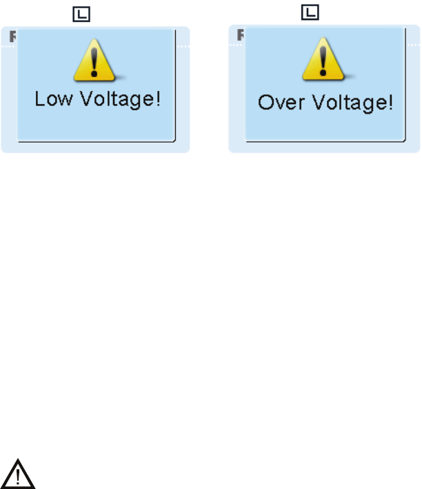
24
Low Voltage Alarm Over Voltage Alarm
Then the repeater will automatically shut off, but the LCD prompt will remain.
You will need to:
1. Use a voltmeter to check if the input voltage of DC power supply is normal, especially
if the voltage will run below the normal range while transmitting. If yes, please replace
the DC power supply or backup battery.
2. Check if connection between the repeater and the DC power cord is loose or lost. If
yes, please secure the connection or replace the cable.
3. If you cannot solve the issue, please contact your local dealer for technical support.
Caution: If low voltage is detected when the repeater is powered by backup battery,
you need to charge the battery with an external charger. Remove the battery from the
repeater when charging.
When voltage falls within the normal range, the LCD prompt will disappear, and the Alarm
Indicator will go out.

25
Troubleshooting
Phenomena Analysis Solution
The repeater cannot
be powered on.
a. Power cord is not connected or is
not securely connected to the
outlet.
b. Power cord fuse is damaged.
a. Properly connect the power cord
and ensure secure connection.
b. Check if the DC fuse has blown,
and if yes, replace it with a new
one.
Group members
cannot talk to each
other, or the repeater
cannot communicate
with a subscriber
radio.
a. TX/RX frequency of the repeater
is inconsistent with that of
portable/mobile terminals.
b. Failed to repeat useful signal due
to strong interference signal.
c. The group member is out of the
coverage of the repeater.
a. Re-set frequencies.
b. If you cannot remove or bypass
the interference source, change to
operate on other frequencies.
c. Go within the coverage of the
repeater.
Group members
cannot talk to each
other, even though
RX indication is
given.
a. Your ID is inconsistent with that of
other group members.
b. Inconsistent CTCSS/CDCSS.
a. Set your ID to the same as that of
other members.
b. Re-set CTCSS/CDCSS.
Short
communication
range or poor audio
a. Leakage of signal energy due to
damaged connection cable.
b. Loose connection between
antenna connector and the cable,
or loss of connection
c. Invisible damage of cable.
d. Duplexer is not properly set (if
duplexer is mounted).
a. Replace the cable with a new one
if necessary.
b. Secure the connection or replace
cable plug with a new one if
necessary.
c. Replace the cable with a new one.
d. Contact the manufacturer or your
dealer to re-set the duplexer.

26
If the above solutions can not fix your problems, or you may have some other queries,
please contact us or your local dealer for more technical support.
Care and Cleaning
To guarantee optimal performance as well as a long service life of your repeater, please
follow the tips below.
Repeater Care
Keep the repeater at a place of good ventilation and heat dissipation to facilitate
normal work.
Do not place irrelevant articles on top of the repeater to ensure optimal heat
dissipation.
Do not place the repeater in corrosive agents, solutions or water.
Repeater Cleaning
Clean up the dust and fine particles on the repeater parts with a clean and dry lint-free
cloth or a brush regularly.
Use a non-woven cloth with neutral cleanser to clean the keys, control knobs, LCD
and jacks after long-time use. Do not use chemical preparations such as stain
removers, alcohol, sprays or oil preparations. Make sure the repeater is completely
dry before use.
Caution: Power off the repeater before cleaning.
2
7
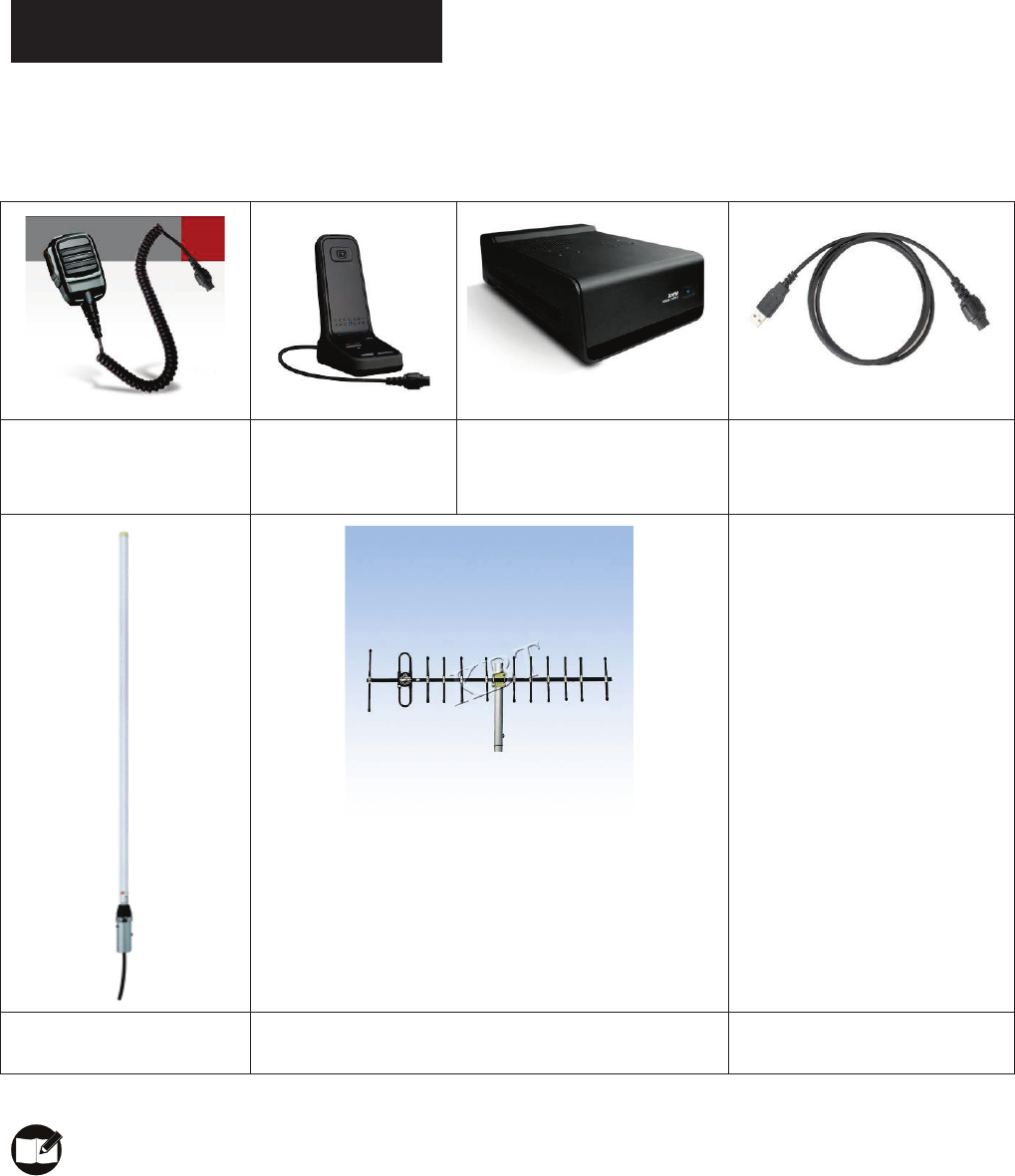
Optional Accessories
The following items are the main optional accessories for the repeater, and please consult
your local dealer for more other accessories.
Palm Microphone SM16A1 Desktop Microphone
SM10A1
External Power Supply (320W,
backup battery applicable)
PS22002
Programming Cable (USB Port)
PC37
Omni-directional Antenna Directional Antenna
Note: Use the accessories specified by Hytera only. If not, Hytera shall not be liable
for any losses or damages arising out of use of unauthorized accessories.
PMR
Frequency Range:210MHz to 270MHz˗
RF Output Power: High Power: 50WˈLow Power: 5W˗
Modulation Type:
Analog Voice: FM, Digital Data: 4FSK;
Channel Separation: Analog Voice: 12.5kHz, Digital Data: 12.5kHz;
Antenna gain: 6.5dBi
Operational Instructions and Training Guidelines
To ensure optimal performance and compliance with the general population/Uncontrolled
environment RF energy exposure limits in the above standards and guidelines, users
should transmit not more than 100% of the time and always adhere to the following
procedures:
● Antenna gain must not exceed 6.5dBi.
●The antenna must be installed complying with the requirements of manufacturer or
supplier, and it must be at least 3.4 meters away from human body.