Hytera Communications RD98XU1 Digital Mobile Radio - Repeater User Manual RD98X Owner s Manual 100202
Hytera Communications Corporation Ltd. Digital Mobile Radio - Repeater RD98X Owner s Manual 100202
UserManual.wiki
>
Hytera Communications
>
RD98XU1 User Manual
User Manual
Navigation menu
Upload a User Manual
Namespaces
Wiki Guide
HTML
PDF
Info
Views
User Manual
Discussion / Help
Navigation
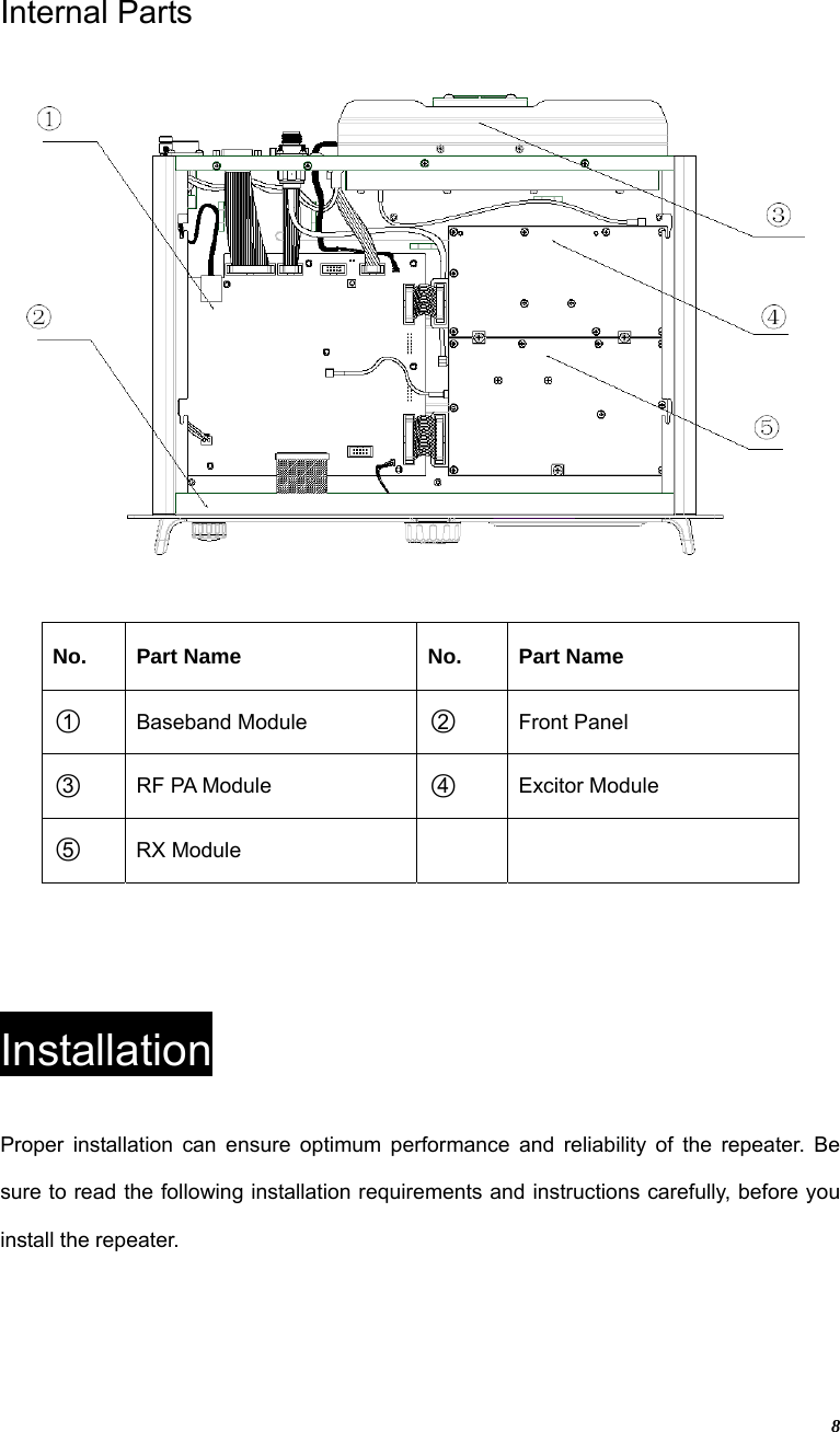
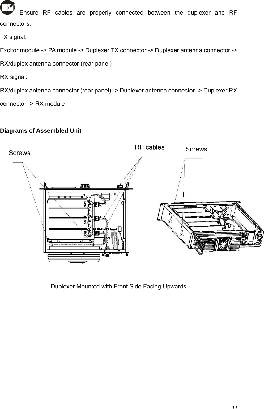
![13 3. Loosen the screw at the back of the top cover, and then pull the top cover to remove it. 4. Loosen the 6 screws locking the PA heatsink, remove all power, data and RF cables from the PA, and finally remove the PA heatsink. 5. Mount the duplexer, and fasten the 2 screws inside the housing and on the side panel respectively. Then mount the PA heatsink, and connect all the lines and cables. 批注 [Iris1]: 优化箭头方向](https://usermanual.wiki/Hytera-Communications/RD98XU1/User-Guide-1310409-Page-14.png)