Hytera Communications TM628HV Mobile Radio User Manual TM 628H Owner s Manual
Hytera Communications Corporation Ltd. Mobile Radio TM 628H Owner s Manual
Users Manual

RF Energy Exposure Compliance
Your radio is designed and tested to comply with a number of national and international standards
and guidelines (listed below) regarding human exposure to radio frequency electromagnetic
energy. This radio complies with the IEEE and ICNIRP exposure limits for
occupational/controlled RF exposure environment at operating duty factors of up to 50%
transmitting and is authorized by the FCC for occupational use only. In terms of measuring RF
energy for compliance with the FCC exposure guidelines, your radio radiates measurable RF
energy only while it is transmitting (during talking), not when it is receiving (listening) or in
standby mode.
Your radio complies with the following of RF energy exposure standards and guidelines
● United States Federal Communications Commission, Code of Federal Regulations; 47CFR
part 2 sub-part J
● American National Standards Institute (ANSI)/Institute of Electrical and Electronic
Engineers (IEEE) C95. 1-1992
● Institute of Electrical and Electronic Engineers (IEEE) C95. 1-1999 Edition
● International Commission on Non-Ionizing Radiation Protection (ICNIRP) 1998
Safety Information
The following safety precautions shall always be observed during operation, service and
repair of this equipment.
z This equipment shall be serviced by qualified technicians only.
z Do not modify the radio for any reason.
z Use only HYT supplied or approved antenna.
z Gain of antenna must not exceed 3.5dBi for VHF or 5.5dBi for UHF.
z Mobile antenna Installation: Install the mobile antenna at least 100cm (34 inches)
away from your body, in accordance with the requirements of the antenna
manufacturer/supplier.
z Transmit only when people inside and outside the vehicle are at least the minimum
distance away from a properly installed, externally mounted antenna.
z Mobile antenna substitution: Don’t substitute HYT supplied or approved antenna, or
excessive radio frequency radiation will result. Please contact your dealer or the
manufacturer for further instructions.
z Please make sure there’s no stress on the antenna joint during transportation or
installation.
z To avoid electromagnetic interference and/or compatibility conflicts, turn off your radio
in any area where posted notices instruct you to do so. Hospital or health facilities
may be using equipment that is sensitive to external RF energy.
z For vehicles with an air bag, do not place a radio in the area over an air bag or in the
air bag deployment area.
z Turn off your radio prior to entering any area with explosive and flammable materials.
z Do not expose the radio to direct sunlight over a long time, nor place it close to
heating source.
▇ Operation Guidelines
For vehicles equipped with electronic anti-skid braking systems, electronic ignition
systems or electronic fuel injection systems, interferences may occur during radio
transmission. If the foregoing electronic equipments are installed on your vehicle, please
contact your dealer for further assistance to make sure that radio transmission will not
interfere with these equipments.
For radio installation in vehicles fueled by LP gas with LP gas container within interior of
the vehicles, the following precautions are recommended for personal safety.
1. Any space containing radio equipment shall be isolated by a seal from the space in
which the LP gas container and its fittings are located.
2. Remote (outside) fitting connections shall be used.
3. Good ventilation is required for the container space.
▇ Installation Guidelines
z Vehicle installation: The antenna can be mounted at the center of a vehicle metal roof
or trunk lid if the minimum safe distance is observed.
z Do not mount the mobile radio overhead or on a sidewall unless you take special
precautions.
z If the mobile radio is not properly installed, road shock could bump the radio loose,
and the falling radio could, in some circumstances, cause serious injury to the driver
or a passenger. In case of vehicle accidents, even when properly installed, the radio
could break loose and become a dangerous projectile.
1
Preface
Thank you for purchasing HYT TM-628H Mobile Radio. This easy-to-use radio will deliver you secure,
instant and reliable communication at peak efficiency.
To derive optimum performance from your radio, please read this manual and the supplied Safety
Information Booklet carefully before use.

2
Icon Information
The following icons are available through this manual:
Caution: indicates situations that could cause damage to your radio.
Note: indicates tips that can help you make better use of your radio.
Copyright Information
HYT and Hytera are trademarks or registered trademarks of HYT in the PRC and other countries and/or
areas. HYT retains the ownership of its trademarks and product names. All other trademarks and/or
product names that may be used in this manual are properties of their respective owners.
The HYT product described in this manual may include HYT computer programs stored in memory or
other media. Laws in the PRC and/or other countries or areas preserve for HYT exclusive rights for HYT
computer programs. The purchase of this product shall not be deemed to grant, either directly or by
implication, any rights to the purchaser with respect to HYT computer programs. Any HYT computer
programs may not be copied, modified, distributed, decompiled, or reverse-engineered in any manner
without the prior written consent of HYT.
Disclaimer
HYT endeavors to achieve the accuracy and completeness of this manual, but no warranty of accuracy
or reliability is given. All the specifications and designs are subject to change without prior notice due to
continuous technology development. No part of this manual may be copied, modified, translated, or
distributed in any manner without the express written permission of HYT.
If you have any suggestions or would like to learn more details, please visit us at: http://www.hyt.cn.
3
Contents
Checking Items in the Package......................................................................................5
Radio Overview ...............................................................................................................6
Front Panel..................................................................................................................6
Rear Panel ..................................................................................................................7
Programmable Function Keys.....................................................................................7
Installation .......................................................................................................................9
Instructions..................................................................................................................9
Installation Tools .........................................................................................................9
Installation Steps.........................................................................................................9
Status Indicators ...........................................................................................................11
LCD Icons .................................................................................................................11
LED Indicator ............................................................................................................12
Basic Operations...........................................................................................................13
Turning the Radio On/Off ..........................................................................................13
Adjusting the Volume ................................................................................................13
Selecting a Channel ..................................................................................................13
Selecting a Zone .......................................................................................................13
Receiving a Call ........................................................................................................13
Transmitting a Call ....................................................................................................14
Selecting the Power Level.........................................................................................14
BOT ID and EOT ID ..................................................................................................14
Functions and Operations ............................................................................................ 15
Monitor ......................................................................................................................15
Scan..........................................................................................................................15
Busy Channel Lockout (BCL) ....................................................................................17
BCL Override ............................................................................................................17
DTMF Call.................................................................................................................17
Code Squelch............................................................................................................19
Off Hook Decode.......................................................................................................20
Time-out Timer (TOT) ...............................................................................................20
Emergency Call.........................................................................................................21
Frequency Reverse...................................................................................................21
Talk Around...............................................................................................................21
Selectable Squelch Level (SQL) ...............................................................................22
User Selectable CTCSS/CDCSS (UST)....................................................................22
Public Address (PA) ..................................................................................................22
Home Channel ............................................................................................................................... 23
Rental........................................................................................................................23
Lone Worker..............................................................................................................24
2-Tone Encode Select (TTS).....................................................................................24
Display Frequency.....................................................................................................24
Display Mode ............................................................................................................24
Voice Compandor......................................................................................................25
Scrambler..................................................................................................................25
4
HDC1200 ..................................................................................................................25
HDC2400TM ...............................................................................................................26
Short Message ..........................................................................................................26
Troubleshooting ............................................................................................................31
Care and Cleaning......................................................................................................... 31
Optional Accessories.................................................................................................... 32
5
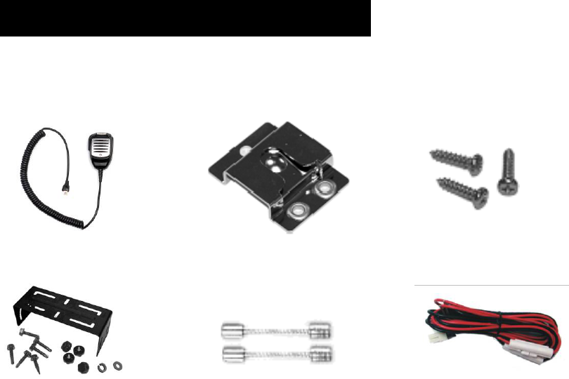
Checking Items in the Package
Please unpack carefully and check that all items listed below are received. If any item is missing or
damaged, please contact your dealer.
Palm Microphone Microphone Hanger Microphone Hanger Screws
Mounting Bracket Kit Fuse Vehicle Power Cord
Owner’s Manual Safety Information Booklet Radio Unit
6
Radio Overview
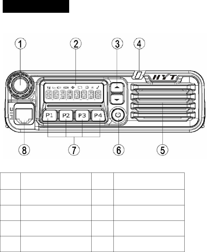
Front Panel
No. Part Name No. Part Name
○
1 Volume Control Knob ○
2 LCD Display
○
3 Programmable Keys ▲/▼ ○
4 LED Indicator
○
5 Speaker ○
6 Power On/Off Key
○
7 Programmable Keys P1-P4 ○
8 Microphone Jack
7
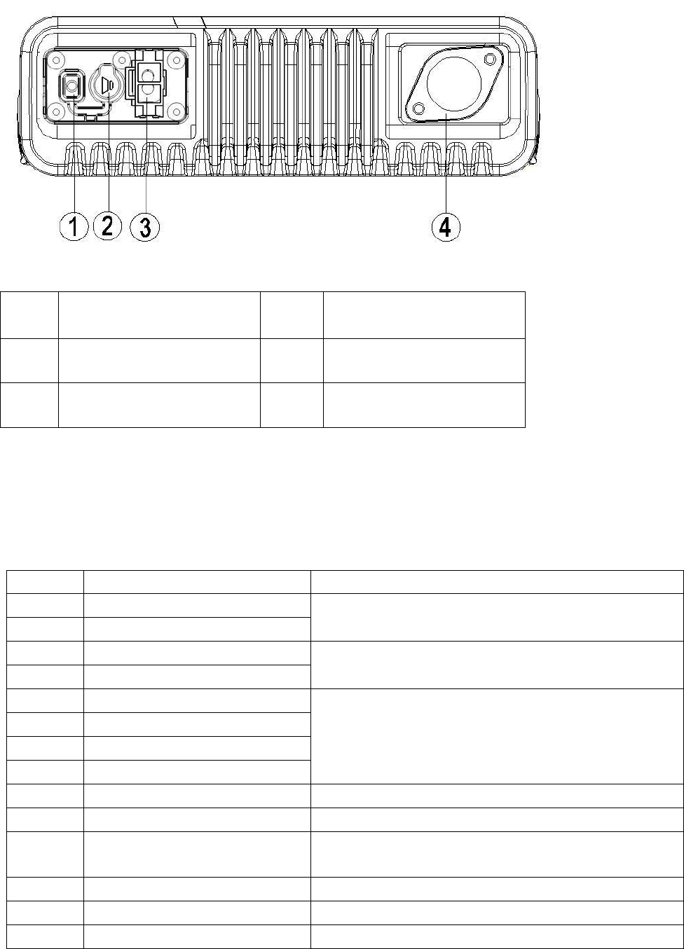
Rear Panel
No. Part Name No. Part Name
○
1 Audio Connector ○
2 External Speaker Jack
○
3 Power Inlet ○
4 Antenna Connector
Programmable Function Keys
For enhanced convenience, you may request your dealer to program the keys P1, P2, P3, P4, ▲ and ▼
as shortcuts to the functions listed below:
No. Shortcut Keys Description
1 CH Up (▲ by default)
2 CH Down (▼ by default) To select a channel quickly
3 Zone Up (P3 by default)
4 Zone Down (P4 by default) To select a zone quickly
5 MONI A
6 MONI B
7 MONI C (P1 by default)
8 MONI D
To adjust the condition for incoming signal match.
9 Display Frequency To display current frequency quickly
10 Display Mode To switch display mode quickly
11 User Selectable Tone (UST) To change the CTCSS frequency of current channel
temporarily
12 2-Tone Select To select 2-Tone code quickly
13 TX Power Select To adjust power level through one button press
14 Scan (P2 by default) To monitor the signals on the predefined channel

8
To add or delete the scan channel in non-scan status
15 Add/Delete To delete the nuisance channel temporarily in scan status
16 Frequency Reverse To reverse the TX and RX frequencies, and the
CTCSS/CDCSS encoding and decoding frequencies
17 Talk Around To transmit with the RX frequency and CTCSS/CDCSS
frequency
18 SEL SQL To select the squelch level quickly
19 Home Channel To switch to the home channel quickly
20 Public Address To output the amplified audio signals
21 Scrambler To safeguard the privacy of your talk through voice
encryption
22 Compandor To bring clearer voice under noisy environment
23 Emergency Call To summon help in emergent situations
24 HDC To select HDC call quickly
25 Lone Worker To ensure the safety of lone workers
26 Whisper To hear clearly even if the transmitting party speaks in
low voice
27 Short Message To quickly access the short message operation
28 Rental To time the rental service
29 Aux A To control the output from the port AUX A
30 Aux B To control the output from the port AUX B
31 Transparent Transmit Mode To enter the Transparent Transmit Mode quickly

9
Installation
Before you install the radio in a vehicle, be sure to read the following instructions carefully:
Instructions
z The radio operates with negative grounded power supply of 13.6 ± 15%V only. Please check polarity
and voltage of the power supply on vehicle before you install the radio.
z Please check how long the screws will extend from the bottom surface of radio, before you install the
radio. Be sure to drill mounting hole with caution, to avoid damage of the vehicle wiring and parts.
z Please connect the supplied antenna and power cord to the radio, before you install the radio in the
bracket.
z Install the radio with HYT supplied mounting bracket, to avoid radio loose in case of accidents. The
loose radio may cause bodily injury.
z Install the radio in a location where it’s easy to reach the front panel controls.
z Please determine the location of mounting hole before drilling.
z Please make sure there’s sufficient space at back of the radio for wiring.
z When the fuse for DC power cord needs replacement, it must be replaced by a fuse with the same
specification.
Installation Tools
z Electric drill: ¢6mm or above
z Cross head screwdriver
z Hex socket sleeve (used for mounting 4.8 × 20 mm self-tapping screw)
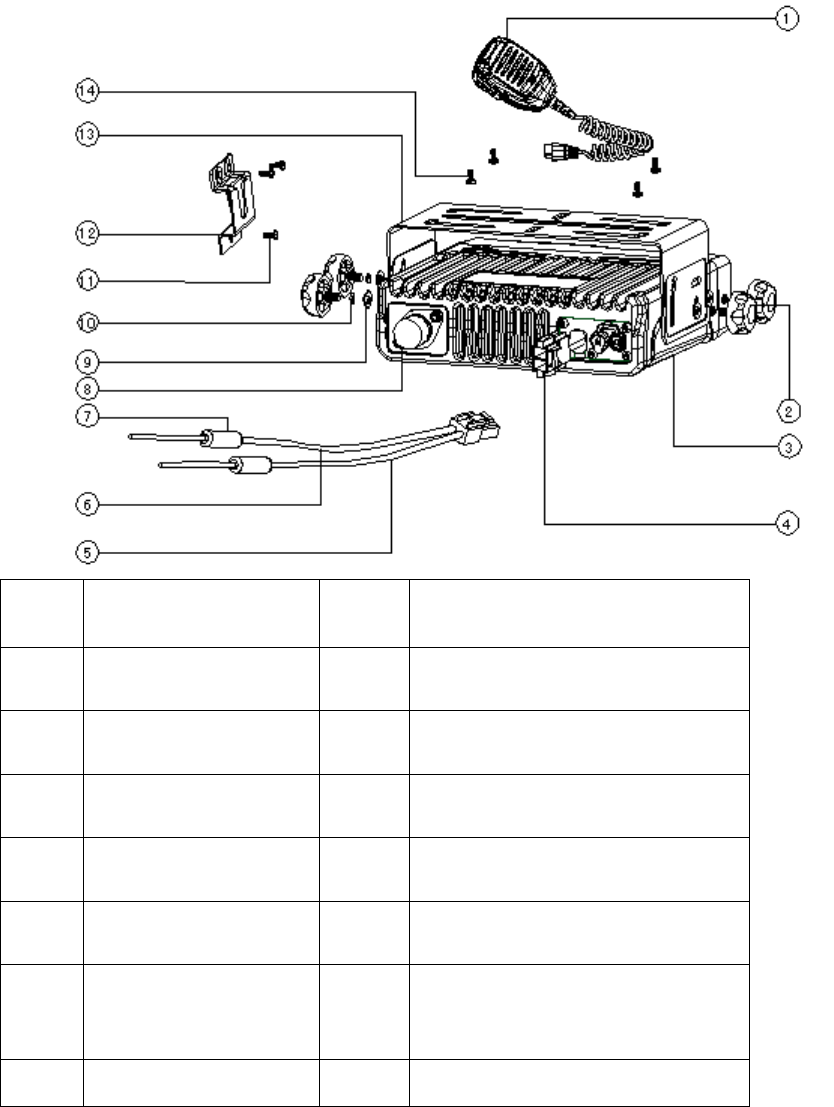
Installation Steps
1. Install the bracket in a location where it’s easy to operate the radio.
2. Connect accessories such as antenna and power cord to the radio.
3. Slide the radio into the mounting bracket and secure it using the locking knobs.
4. Install the microphone hanger in a location where it’s easy to reach the microphone.
5. Plug the palm microphone into the microphone jack on the front panel, and place it on the hanger
when you do not use it.
10
No. Part Name No. Part Name
○
1 Palm Microphone ○
2 Adjust Knobs
○
3 Radio unit ○
4 Power Inlet
○
5 Black Power Cord ○
6 Red Power Cord
○
7 Fuses ○
8 Antenna Connector
○
9 Flat Washers ○
10 Spring Washers
○
11 4 × 16 mm
Self-tapping Screws ○
12 Microphone Hanger
13 Mounting Bracket 14 4.8 × 20 mm Self-tapping Screws
11
Status Indicators
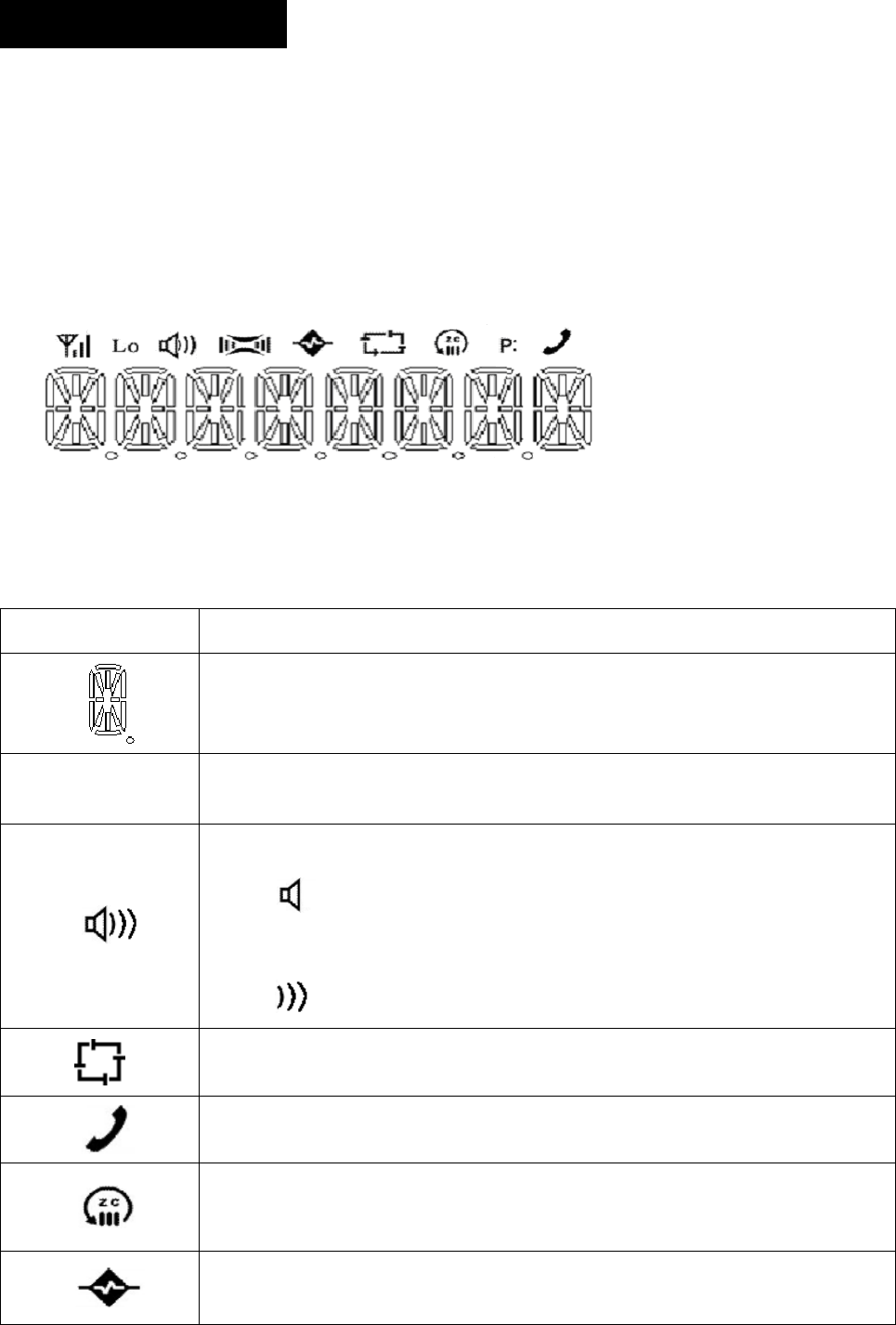
LCD Icons
The LCD of your radio displays the radio status. The following are the icons that appear on the radio’s
display.
LCD panel
Status Icons
Indicator Description
Displays CH number/name, zone number/name, DTMF number, frequency,
menu and options, etc.
Lo Indicates low power output.
Press the Monitor key:
1. The icon is displayed when CTCSS/CDCSS and 2-Tone decoding is
off.
2. The icon is displayed when the speaker is unmuted.
Appears when the radio begins to scan.
Appears when the radio is transmitting a selected call.
C indicates that the current channel is in the scan list.
Z indicates multi zone scan.
Appears when the Scrambler feature is enabled.
12
Appears when the Compandor feature is enabled.
Appears when the current channel is already in use.
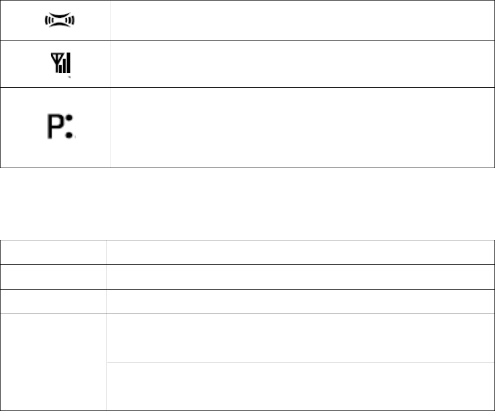
Indicates the current channel is the priority channel. P• indicates priority
channel 1, P. indicates priority channel 2, P: indicates priority channels 1 and
2.
LED Indicator
The LED indicator will help you easily identify current radio status.
LED Indicator Radio Status
LED glows red Transmitting
LED glows green Receiving
After the 2-Tone, HDC1200 or HDC2400TM or DTMF signaling is decoded, and
during the auto reset time.
LED flashes orange After the 2-Tone, HDC1200, HDC2400TM or DTMF signaling is transmitted, and
during the auto reset time.

13
Basic Operations
Turning the Radio On/Off
Press the Power On/Off key to turn on the radio.
Press and hold down the Power On/Off key for about 1 second to turn off the radio.
Adjusting the Volume
Turn the Volume Control knob clockwise to increase the volume, or counter-clockwise to decrease the
volume.
Note: During adjusting, if the radio is programmed with CTCSS/CDCSS or 2-Tone, HDC1200,
HDC2400TM Signaling squelch, noise will not be heard from local speaker even though you
turn the Volume Control knob fully clockwise.
Selecting a Channel
The ▲/▼ and P1-P4 function keys are programmable by your dealer to select a channel. The RX/TX
frequency on each channel is set by your dealer.
Press the programmed CH Up key to select a higher numbered channel; press the programmed CH
Down key to select a lower numbered channel.
Selecting a Zone
The ▲/▼ and P1-P4 function keys are programmable by your dealer to select a zone. The RX/TX
frequency on each channel is set by your dealer.
Press the programmed Zone Up key to select a higher numbered zone; press the programmed Zone
Down key to select a lower numbered zone.
Receiving a Call
If CTCSS/CDCSS, 2-Tone, HDC1200 or HDC2400TM is set on the current channel by your dealer, you
can receive calls with matched signaling only. If CTCSS/CDCSS, 2-Tone, HDC1200 or HDC2400TM is
not set, you can hear from all the users on the same channel.

14
Transmitting a Call
When transmitting a call, please follow steps below:
1. Hold down the PTT key on the microphone.
2. Speak into the microphone. The red LED lights during calling.
3. Release the PTT key to return to the RX mode.
4. When the transmission ends, put the microphone on hook.
Selecting the Power Level
If the current channel is programmed with high power by your dealer, the power output toggles between
high and low upon each press of the programmed Tx Power Select key. The LO icon is displayed on
LCD to indicate low power.
A lower power level saves battery and reduces the possibility of interference. Use the high power setting
only when necessary.
Note:
If the current channel is programmed with lower power, any Tx Power Select key press will prompt
an error tone, and the power level will not change.
If you switch to low power on a channel that was set with high power, this configuration will work on
all other channels that were set with high power.
BOT ID and EOT ID
Your dealer may configure whether to transmit Connect ID (BOT ID) and Disconnect ID (EOT ID), when
connecting or disconnecting a repeater or telephone system. The following modes are programmable:
1. Press the PTT key, and the BOT ID is transmitted.
Release the PTT key, and the EOT ID is transmitted. .
2. Press the * key while holding down the PTT, and the BOT ID is transmitted.
Press the # key while holding down the PTT, and the EOT ID is transmitted.

15
Functions and Operations
Monitor
If the Monitor function is set by your dealer, press the programmed Monitor key in Rx mode to get aware
of the activities on the current channel.
The Monitor key is programmable with one of the following four operating modes by your dealer:
1. Carrier Squelch-Momentary
Hold down the Monitor key to open CTCSS/CDCSS/2-Tone Signaling squelch, and release the key to
close the Signaling squelch.
2. Carrier Squelch-Toggle
Press the Monitor key to open CTCSS/CDCSS/2-Tone Signaling squelch. Press again to close the
Signaling squelch.
3. Squelch Off-Momentary
Hold down the Monitor key to open carrier squelch, and release the key to close the carrier squelch.
4. Squelch Off-Toggle
Press the Monitor key to open carrier squelch. Press again to close the carrier squelch.
Scan
▇Scan Type
1. Single Zone Scan
The radio scans all the channels added into the scan list on the current zone.
2. Multi Zone Scan
Multiple zones added into a multi scan list can be scanned. All channels within the zones added into the
scan list can be scanned.
▇Scan Start
1. Add one or more non-priority channels into the scan list.
2. Press the programmed Channel Scan key to initiate scan from the current channel (please scan the
channels one by one in accordance with the list). The LCD displays SCAN (-SCAN- for multi zone
scan) and the icon.
▇Scan Cease

16
The scanning pauses or ceases upon the following:
1. Press the programmed Channel Scan key and cease the scanning, so that the radio may exit the
scan mode.
2. Activate the Monitor function.
3. The radio receives the carriers which satisfy radio unmute condition
▇Scan Resume
If the scanning pauses on an active channel, it will resume according to the scan resume mode. The
scan resume mode can be programmed by your dealer with Carrier operated scan or Time operated
scan.
1. Time Operated Scan
Scanning remains on an active channel for a programmed time period (programmable by your dealer).
Once the timer expires, the radio will begin scanning other channels even if the active channel is still
busy.
2. Carrier operated scan
If carriers are detected during the scan sequence, scanning will remain on the active channel until there
is no activity.
▇Dual Priority Scan
If dual priority channels are programmed by your dealer, the radio will check the dual priority channels for
activity regularly on the non-priority channels. If carriers are detected on a priority channel, the radio will
immediately switch to this active priority channel.
LCD displays the “P" icon to indicate the Priority Channel 1, the “P. ” icon to indicate the Priority Channel
2, and the “P:” icon to indicate the channel is programmed with Priority Channel 1 and 2 simultaneously.
▇Scan Add/Delete
If the Scan Add/Delete feature is enabled by your dealer, the current channel can be added to/deleted
from the scan list in the following procedures:
1. Select the channel to be added/deleted in the non-scan mode.
2. The current channel toggles between Add/Delete status upon each press of the programmed Scan
Add/Delete key.
Note: Only channels added into the scan list can be scanned.
Nuisance Channel Delete▇

17
Channels in the scan list are allowed to be temporarily deleted
When the scan pauses on an unwanted channel, such as a nuisance channel, press the programmed
Add/Del Scan key to temporarily delete the channel from the scan list, and then the scan reinitiates
immediately.
Note: The temporarily deleted channel will recover its settings prior to the scan after the radio
exits the scan mode.
▇Revert Channel
If you press the PTT key, the scan will be turned off and the radio will switch to the Revert Channel to
transmit. This feature is programmable by your dealer.
▇Off-Hook Scan
If this feature is enabled by your dealer, the radio will be allowed to scan no matter whether the palm
microphone is in an off hook position or not. Otherwise, the scan will be disabled with an off-hook palm
microphone.
Busy Channel Lockout (BCL)
The feature helps prevent transmission on a channel that is already in use, and it can be
enabled/disabled by your dealer. If you press the PTT key on a busy channel, transmission will be
inhibited and an alert tone will sound. If the PTT key is released, the alert tone will cease and the radio
will return to Rx mode. When the channel is free, press the PTT key again to transmit.
BCL Override
If this feature is enabled, you can override the BCL feature to transmit on a busy channel. If you press
the PTT key, a BCL alarm will be heard; press the PTT key again within 0.5 seconds to override the BCL
feature and transmit on the busy channel.
DTMF Call
▇Manual Dial
Hold down the PTT key, and then press any key on the DTMF keypad of the microphone to transmit the
corresponding DTMF signal. Meanwhile, you may hear relevant tones.
Release the PTT key to remain transmission for 2 seconds (programmable by your dealer), and then
press another numeric key within 2 seconds to continue the transmission.

18
▇Keypad Auto PTT
If this feature is enabled by your dealer, press any numeric key to transmit DTMF signal without PTT key
press.
Stor▇e & Send
When this feature is enabled, enter a pre-stored DTMF number (up to 16 digits) in Rx mode, and then
press the PTT key on the microphone to initiate a call; simultaneously, the dialed DTMF number scrolls
across the LCD, and the corresponding DTMF tone can be heard.
Note:
If you have dialed a wrong number or you want to cancel the dialing, you just simply press any key
on the front panel other than the Power On/Off key to exit.
“D” can be programmed by your dealer as a blank tone, that is, if you enter “D”, the tone will not be
heard during transmission, but there will be a delay in time, which is programmable by your dealer.
▇DTMF Speed
The DTMF number is programmable by your dealer.
The feature is designed to reduce decoding errors by providing a fixed interval between digits. It is 10
DTMF numbers per second by default.
▇Store the DTMF Number
You are allowed to store a DTMF number (up to 16 digits) in 32 Speed Dial memories respectively as
follows:
1. Press the # key on the microphone keypad, and the LCD displays D ------.
2. Enter the desired number (range from 0~9, A~F) via the microphone keypad. If you want to enter A, B,
C, D, E and F, hold down the PTT key and then enter 2, 5, 8, 0, * and # respectively.
3. Press the # key, and “D” on the LCD is followed by a symbol “ --”, which indicates the location to enter
memory numbers.
4. Enter the desired memory number (01~32).
5. Press the # key again on the microphone, and then the entered number is stored into its
corresponding memory.
If you have dialed a wrong number or you want to cancel the dialing, please press any key on the front
panel other than the Power On/Off key to exit.
▇Confirm the Stored DTMF Numbers

19
1. Press the * key on the microphone keypad, and then the LCD displays A --.
2. Enter the memory number (01~32), and the LCD displays the stored number or its alias.
3. Press any key other than the PTT, and the LCD resumes its initial display.
▇Auto Dial
1. Press the * key on the microphone keypad, and then the LCD displays A --.
2. Enter the memory number (01~32), the LCD displays the stored number or its alias.
3. Press the PTT key, and then the number is transmitted.
▇Clear Stored DTMF Numbers
1. Press the # key on the microphone keypad, and then the LCD displays D ------.
2. Press the # key again on the microphone keypad, and then the LCD displays Clear --.
3. Enter the memory number to be cleared (01~32), and press any key other than 0~9 keys to cancel
this operation.
4. Press the # key on the microphone keypad, and then the stored numbers are cleared.
▇Redial
1. Press the * key on the microphone keypad, and the LCD displays A --.
2. Press 0 twice, and the last dialed number (up to 16 digits) is dialed and displayed on LCD.
3. Press the PTT key, and the number is transmitted.
Note: The redial memory can be cleared by powering off the radio.
Code Squelch
This feature can be enabled/disabled by your dealer. If it is enabled, the preset 2-Tone will control the
radio mute/unmute. The radio will not unmute until matched signaling is received.
▇Receive
1. Radio is unmuted when the matched 2-Tone signaling (programmed by your dealer) is received, and
the user can hear from the transmitter without any other operation.
2. The icon flashes on the LCD, and the LED flashes orange.
3. Radio is muted upon the programmed Monitor key press, or no signal is received within the preset
time period.
4. If the alert tone is enabled, radio will emit alert tone when match signaling is received. If the
Transpond feature is enabled, the radio will transpond a tone to the calling radio. However, radio will not

20
transpond if a zone call is received.
▇Transmit
1. Hold down the PTT key
2. During encoding, the LED lights red.
Please refer to the TTS key for 2-Tone encoding.
3. Upon release the PTT key, the signaling squelch is disabled; the icon flashes on the LCD,
and LED flashes orange. The LED lights green while signal is received, and flash orange if signal off.
4. If the programmed Monitor key is pressed, or no signal is received within the preset time period, the
signaling squelch is enabled.
Off Hook Decode
If this feature is enabled by your dealer, CTCSS/CDCSS signaling is active no matter whether the palm
microphone is in an off hook position or not. If the feature is disabled, CTCSS/CDCSS signaling is
disabled with an off-hook palm microphone is in the off hook condition.
Time-out Timer (TOT)
▇Time-out Timer (TOT)
This feature is able to prevent any single user from using a channel for an extended period, and to
protect the radio against damage caused by prolonged transmission.
If the preset time (off, 15~1200 seconds) expires, the radio will automatically terminate transmission and
keep beeping. Beeps will not stop unless the PTT key is released.
The TOT default is 180 seconds, which can fully satisfy common users. Any change should be permitted
by professional technicians.
▇TOT Pre-alert
With a TOT Pre-alert timer, the radio can generate pre-alert tone at the programmed time (1~10 seconds
before the TOT timer expires).
▇TOT Re-key Time
The radio features a TOT Re-key timer. If the transmission is terminated due to expiration of the TOT
timer, the TOT Re-key timer will be activated. The transmission will be inhibited if the PTT key is pressed
before the expiration of TOT Re-key timer (programmable by your dealer as Off, 1~60 seconds).
21
▇TOT Reset Time
The TOT Reset timer is activated upon release of the PTT key. And the TOT timer will not be reset until
the TOT Reset timer expires. Press the PTT key before the TOT Reset timer expires, and the TOT timer
continues to countdown.
The TOT Reset Time (Off, 1~15 seconds) is programmable by your dealer.
Emergency Call
Hold down the Emergency Call key (the exact time to hold down the key can be programmable), and
the radio will enter the Emergency Call mode and switch to the preset Emergency Zone/Channel. The
radio will transmit within a preset time period and then receive within a preset time period circularly.
Press and hold down the Emergency Call key (the exact time to hold down the key can be
programmable), and the radio will return to its original channel.
Frequency Reverse
If communications between radios are disrupted due to a long distance away from the repeater, the
Frequency Reverse function can be applied to re-establish communications with other radios. When this
function is activated, the Tx and Rx frequencies will be reversed. The preset CTCSS/CDCSS encoding
and decoding processes will also be reversed.
Press the Frequency Reverse key (programmable function key) to toggle the Frequency Reverse
function ON or OFF.
Enabled Disabled
Talk Around
If the Talk Around feature is enabled, the radio will transmit at its Rx frequency, and the CTCSS/CDCSS
signals will be encoded by decoding signals.
Press the Talk Around key (programmable function key) to toggle the Talk Around function ON or OFF.

22
Enabled Disabled
Selectable Squelch Level (SQL)
1. Press the SQL key (programmable function key), and the LCD displays the current squelch level as
shown below:
2. Select the desired squelch level via the programmable function key ▲/▼.
3. Press any key of P1-P4 to save the selected squelch level. The LCD resumes its initial display.
Note: High squelch level may cause the radio to ignore weak signals; while low squelch level may
cause noise or other unwanted interference.
User Selectable CTCSS/CDCSS (UST)
If the UST feature is enabled by your dealer, the user can temporarily change the CTCSS/CDCSS codes
preset on the current channel. Operations are as follows:
1. Select a desired channel.
2. Press the programmed UST key, and the radio enters the UST mode.
3. Use the ▲/▼ keys to make a selection from the preset UST codes (the newly selected
CTCSS/CDCSS code is valid in the UST mode only), then the CTCSS/CDCSS code on the current
channel is set as the selected UST code.
4. Press the UST key again to exit the UST mode, and then the LCD resumes its initial display.
Note: The UST code will be automatically memorized after channel switch or power-off if the UST
BackUp function is enabled. Otherwise, no codes will be memorized.
Public Address (PA)
The PA feature amplifies audio inputted from the microphone, and the audio can be heard from the
external speaker.
1. Press the programmed PA to activate the PA feature, and then the LCD displays PA.
Press PA again to disable the PA feature, and then the radio returns to normal user mode.
2. In PA mode, the radio is unable to transmit and receive.

23
3. Speak into the microphone after PTT is held down, the PA process initiates, and the LCD
displays PA ON. When the PA process initiates in PA mode, you can adjust the volume via the
volume control knob.
4. Release the PTT key to end the PA process, then the radio returns to the PA mode, and the LCD
displays PA.
Note: When the PA system is operating, the optional PA accessories and external speaker must
be installed by your dealer.
Home Channel
Press the programmed Home Channel key, and the radio will promptly go to the programmed home
channel.
When dual home channels are set, press the programmed Home Channel key to promptly go to Home
Channel 1, press again to promptly go to Home Channel 2, and press for the third time to return to the
original channel.
Rental
Display Format:
Press the Rental key (programmable function key), and the LCD will display the remaining rental time by
2 time units such as “13D 21H”. The LCD will display the hour and minute such as “14H 30M” if the
remaining time is less than one day, or the minutes only such as “30MIN “ if less than an hour.
Auto Reminder:
1. Remind you of the remaining rental time every time the radio is powered on (last for 5 seconds).
2. Remind you every 20 minutes if the remaining rental time is less than one hour. (with displayed
remaining rental time and beeps for 5 seconds)
3. Remain the Remind status during the last minute of the rental time (with displayed EXPIRING
and beeps).
4. An alert tone will be heard during the last minute of the rental time. Once the time expires, the
LCD displays EXPIRED, then the radio will be disabled to transmit or receive with an invalid
keypad.
24
Lone Worker
When this function is enabled, an alert tone will sound if the preset time elapses. Then the user must
press any key to indicate that he/she is safe, otherwise the emergency procedure will be activated. This
feature provides an added security and safety feature for individuals who work remotely from their team.
Operations are detailed as follows:
1. Upon press of the Lone Worker function key, the LCD will display LONE ON, and the Lone Worker
function will be activated.
2. If no key is pressed after the preset time, the radio will continuously sound the Lone Worker alert
tone during the preset time, and then enter the emergency mode.
3. If there is any key press before the radio enters the emergency mode, the Lone Worker timer will be
reset and the Lone Worker function will be re-activated.
4. If the Lone Worker key is pressed, the LCD will display LONE OFF, and the Lone Worker function
will be disabled.
2-Tone Encode Select (TTS)
1. Press the programmed TTS key, the LCD displays its preset 2-Tone number or alias. The LCD
scrolls the alias if it exceeds 8 digits.
2. Press ▲/ ▼ to select 2-Tone number (01~32) or alias.
3. Holding down PTT to transmit the selected code.
4. Upon release of PTT, the signaling squelch is disabled and the LED flashes orange. The LED lights
green when the signal is received, and flashes orange if the signal disappears.
5. If the programmed Monitor key is pressed, or no signal is received within the preset time period, the
signaling squelch will be enabled.
Display Frequency
Upon press of the programmed Display Frequency key, the LCD displays the frequency of the current
channel.
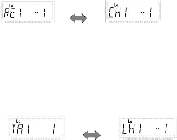
Display Mode
Upon press of the programmed Display Mode key, the radio toggles among the following 5 display
modes:

25
1. Channel alias.
2. Zone number followed by channel number, such as “1 –CH 1”.
3. Zone alias.
4. Channel frequency.
5. Channel number followed by zone number, such as “CH 1– 1”.
Voice Compandor
Press the programmed Voice Compandor key to toggle the voice Compandor feature ON or OFF. When
the feature is enabled, the LCD displays the icon.
Scrambler
Press the programmed Scrambler key to toggle the Scrambler feature ON or OFF. When the feature is
enabled, the LCD displays the icon.
Note: The emphasis/de-emphasis feature is disabled when the Scrambler is ON, and enabled
when the Scrambler is OFF.
HDC1200
HDC call list select (HDC List)
1. Press the HDC Call Select key (Programmable function key) and the preset number or alias in the
HDC list will be displayed on the LCD.
2. Press ▲/▼ to make an selection from the preset options in the HDC call menu, and then press P4
to access the options.
3. Press PTT or P4 to transmit the call.
The HDC signaling can achieve selective call (individual call, zone call, fleet call and broadcast), call
alert and system functions (Stun, Revive and Safety Check), etc.
System call features the following functions:
Stun----permits an authorized radio to disable another radio from a remote place, making it capable
of receive only.
Revive----permits an authorized radio to revive a stunned or killed radio from a remote place.
Safety Check----permits the dispatch center or an authorized radio to transmit the Safety Check
26
message. The receiver radio will reply with a message automatically upon receipt of the Safety
Check message.
HDC2400TM
HDC call list select (HDC List)
1. Press the HDC Call Select key (Programmable function key) and the preset number or alias in the
HDC list will be displayed on the LCD.
2. Press ▲/▼ to make an selection from the preset options in the HDC call menu, and then press P4
to access the options.
3. Press PTT or P4 to transmit the call.
The HDC signaling can achieve selective call (individual call, zone call, fleet call and broadcast), call
alert and system functions (Stun, Revive and Safety Check)), etc.
System call features the following functions:
Stun----permits an authorized radio to disable another radio from a remote place, making it capable
of receive only.
Revive----permits an authorized radio to revive a stunned or killed radio from a remote place.
Safety Check----permits the dispatch center or an authorized radio to transmit the safety Check
message. The receiver radio will reply with a message automatically upon receipt of the Safety
Check message.
Short Message
The short message function is based on HDC2400TM technology platform. Thus the optional signaling
must be set to HDC2400TM on the current channel for both the transmitting and receiving radios.
The short message function is operated through multi-level menu, which can realize the function of Edit,
Save, Read, Send, Protect and Delete of short message. Press the Message key (programmable
function key) in user mode to enter the short message menu.
The short message inbox can save up to 32 short messages, with each containing up to 48
alphanumeric characters.
The short message outbox can save up to 8 short messages, with each containing up to 48
alphanumeric characters.
The radio supports up to 32 fixed short messages, with each containing up to 31 alphanumeric
characters.
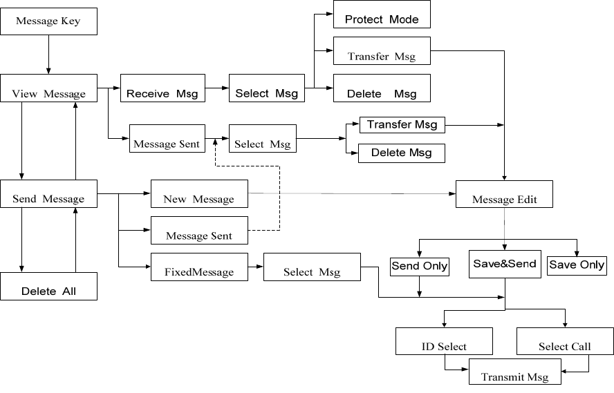
27
The general operations of short message are shown in the following flowchart:
Menu operations are as follows:
1) Press P4 to confirm;
2) Press P1 to back to the previous menu;
3) Press ▲/▼ to perform menu selections.
Read A Short Message
If the alert tone or short message icon is set, the radio will give the preset alert when a short message is
received. (At this time, press the Message key to read the received message.)
Send and Delete A Short Message
When SEND MSG is selected from the main menu, three options are available:
1) Create a message: the LCD will display NEW MSG.
2) Sent a message: the LCD will display MSG SEND.
3) Fixed message: the LCD will display FiXEDMSG.
1. Send A Newly Created Short Message
1) Select a zone and a channel.
2) Press the Message key (programmable function key) to access the short message menu, and
then select the SEND MSG option.
28
3) Select the NEW MSG option.
4) Input the message you want to send. (See Note 1.)
5) Select SENDONLY, SENDSAVE and SAVEONLY.
If SENDONLY or SENDSAVE is selected, go with the following steps:
6) Choose to send to individual / group etc.
7) Use ▲/▼ to input the receiver’s ID (Individual / Group, etc). (See Note 1.)
The user may also press P4 to access the ID menu without inputting the ID.
8) Press P4 or PTT to send the selected message.
2. Send and Delete A Sent Short Message
1) Select a zone and a channel.
2) Press the Message key (programmable function key) to access the short message menu, and
then select the SEND MSG option.
3) Select the MSG SEND option.
4) Use ▲/▼ to select the message you want to send. (See Note 2.)
5) Select TRANSFER or DELETE.
Select DELETE to delete the selected short message;
Select TRANSFER to go with the following steps:
6) Choose to send to individual/group, etc.
7) Use ▲/▼ to input the receiver’s ID (Individual / Group, etc). (See Note 1.)
The user may also press P4 to access the ID menu without inputting ID.
8) Press P4 or PTT to send the selected message.
3. Send A Fixed Short Message:
1) Select a zone and a channel.
2) Press the Message key (programmable function key) to access the short message menu, and
then select the SEND MSG option.
3) Select the FIXEDMSG option.
4) Choose the fixed message you want to send. (See Note 2.)
5) Choose to send to individual/group, etc.
6) Use ▲/▼ to input the receiver’s ID (Individual/Group, etc). (See Note 1.)
29
The user may also press P4 to access the ID menu without inputting ID.
7) Press P4 or PTT to send the message.
Read and Delete A Short Message
When VIEW MSG is selected from the menu, two options are available:
1) Read the received short message, the LCD will display RECEIVED.
2) Read the sent short message, the LCD will display MSG SEND.
1. Read and Delete A Short Message from the Inbox
1) Select a zone and a channel.
2) Press the Message key (programmable function key) to access the short message menu, and
then select the VIEW MSG option.
3) Select the RECEIVED option.
4) Use ▲/▼ to select the ID of the short message you want to read.
5) Use ▲/▼ to select the desired short message. (See Note 1.)
6) Select PROTECT, TRANSFER and DELETE. (See Note 3).
Select DELETE to delete the selected message.
Select TRANSFER to go with the following steps:
7) Choose to send to individual / group, etc.
8) Use ▲/▼ to input the receiver’s ID (Individual / Group, etc). (See Note 1.)
The user may also press P4 to access the ID menu without inputting ID.
9) Press P4 or PTT to send the message.
2. Read and Delete A Short Message from the Outbox:
1) Select a zone and a channel.
2) Press the Message key (programmable function key) to access the short message menu, and
then select the VIEW MSG option.
3) Select the MSG SEND message.
4) Use ▲/▼ to select the short message you want to read. (See Note 2.)
5) Select TRANSFER or DELETE option.
Select DELETE to delete the selected message.
Select TRANSFER to go with steps 7)~9) described in Read and Delete A Short Message from

30
the Inbox.
Delete All the Received Messages
When DEL ALL is selected from the menu, all the received messages except protected ones will be
deleted upon press of P4.
1) Press the Message key (programmable function key) to access the short message menu, and
then select the DEL ALL option.
2) Press P4 to delete all the received messages.
Note:
1. Input content and ID of the short message through the following keys: P1: to delete all, P2: to switch
between entry methods, P3: to move the cursor leftward, P4: to move the cursor rightward with the
first press, and confirm the entry with a second press.
2. If there is no saved message, the LCD will display EMPTY, and all further operations are inhibited.
3. If the selected message is set to Protected, the LCD will display the “P” icon. Press P4 to switch
between the Protected and Unprotected modes. Messages set to Protected can not be deleted.

31
Troubleshooting
Phenomena Analysis Solution
The equipment can not
be powered on.
The power cord may be
unconnected. Connect the power cord correctly.
You can not log on to
the system. The antenna is not connected. Connect the antenna properly.
The crystal connector is inserted
improperly or not inserted.
Insert the crystal connector
correctly.
You can not use the
keys. The keys may fail to function
temporarily. Restart the radio.
The radio can not lock
out.
This feature may malfunction
temporarily. Restart the radio.
There is no display. The LCD may fail to function
temporarily. Restart the radio.
Care and Cleaning
To guarantee optimal performance as well as a long service life of your mobile radio, please follow the
tips below.
Radio Care
Keep the mobile radio at a place with good ventilation and heat dissipation to facilitate normal work.
Do not place irrelevant articles on top of the mobile radio to ensure optimal heat dissipation.
Do not place the mobile radio in corrosive agents, solutions or water.
Radio Cleaning
Clean up the dust and fine particles on the radio parts with a clean and dry lint-free cloth or a brush
regularly.
Use a non-woven fabric with neutral cleanser to clean the keys, control knobs, LCD and jacks after
long-time use. Do not use chemical preparations such as stain removers, alcohol, sprays or oil
preparations. Make sure the mobile radio is completely dry before use.
Caution: Power off the mobile radio before cleaning.
32
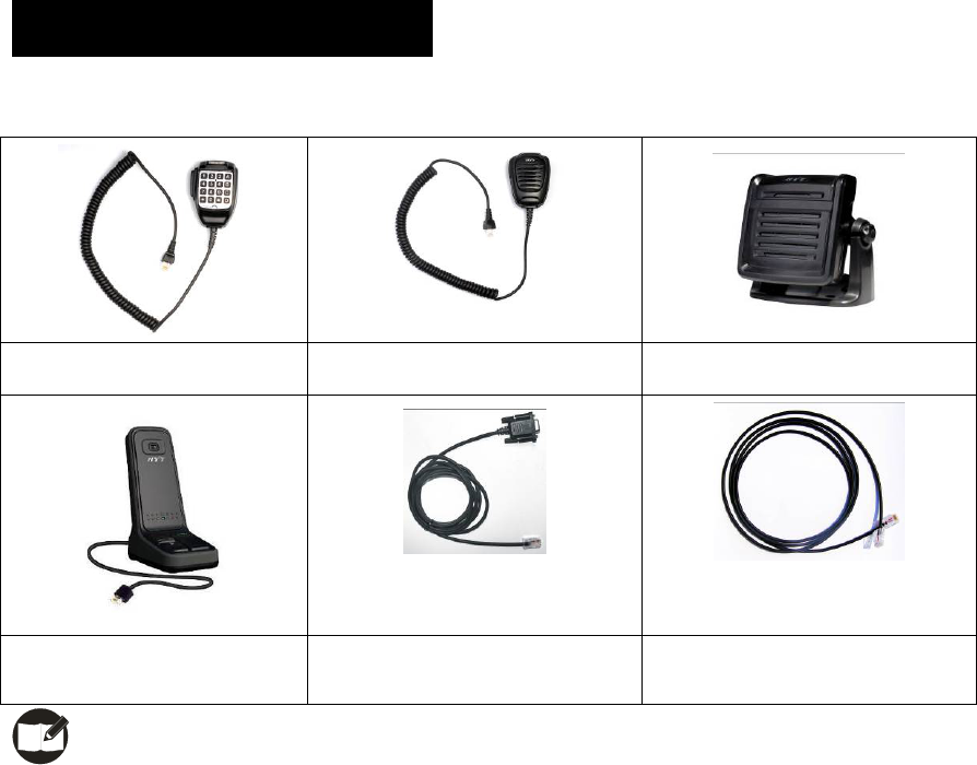
Optional Accessories
The following items are the main optional accessories for the radio, and please consult your local dealer
for more other accessories.
Keypad Microphone SM07R1 Palm Microphone SM07R2 External Speaker SM09S2
Desktop Microphone SM10R2 Programming Cable (COM Port)
PC21
Cloning Cable CP06
Note: Use the accessories specified by HYT only. If not, HYT shall not be liable for any losses or
damages arising out of use of unauthorized accessories.