Hytera Communications Z1PF5 TETRA Terminal User Manual
Hytera Communications Corporation Ltd. TETRA Terminal Users Manual
Contents
- 1. Users Manual
- 2. User Manual
Users Manual

12
Preface
Thanks for your favor in our product. To derive optimum performance from the product, please read
this manual, the corresponding TETRA Terminal Series Feature Book and the Safety Information
Booklet carefully before use.
This manual is applicable to the following model:
Z1p TETRA Portable Terminal

13
Term
Individual Call
A half-duplex or full-duplex call
initiated by an individual user
to another individual user.
Group Call A half-duplex call initiated by
an individual user to a group.
Half-duplex
Half-duplex communication is
also called “two-way alternate
communication”. It indicates
the communication is provided
in both directions, but only one
direction at a time, that is, only
one party is allowed to transmit
or receive at a time.
Full-duplex
Full-duplex communication
is also call ed “fu ll-du plex
synchronous communication”.
It indicates the communication
is allowed in both directions
simultaneously, that is, both
p a r t i e s c a n tr a n s m i t a n d
receive at the same time.
Direct Mode
Operation
(DMO)
DM O su pp or ts half-duplex
o p erati o n a n d a l l o w s t he
ter mi nal s to co mmu ni cat e
directly with each other, without
u s i n g a T E T R A n e t w o r k
infrastructure. Thus functions
that require network access,
such as telephone call, will be
unavailable.
Trunked
Mode
Operation
(TMO)
TMO s up ports e ither h alf-
duplex or full-duplex operation
a n d a l l o w s t h e t e r m i n a l s
to c om municate w it h ea ch
other via the TETRA network
infrastructure. Thus functions
that require network access are
available. To operate in TMO
mode, the terminal must be
granted authorization by your
service provider, and must stay
within the network coverage.
Disclaimer
Hytera Communications Co., Ltd. (the Company)
e n d e a v o r s t o a c h i e v e t h e a c c u r a c y a n d
completeness of this manual, but no warranty of
accuracy or reliability is given. All the specifications
and designs are subject to change without notice due
to continuous technology development. No part of
this manual may be copied, modified, translated, or
distributed in any manner without the express written
permission of us.
We do not guarantee, for any particular purpose,
the accuracy, validity, timeliness, legitimacy or
comple teness of t he Th ird Party p roducts and
contents involved in this manual.
If you have any suggestions or would like to learn
more details, please visit our website at: http://www.
hytera.com.
FCC Statement
This equipment has been tested and found to comply with the limits for a Class B digital
device, pursuant to part 15 of FCC Rules. These limits are designed to provide
reasonable protection against harmful interference in a residential installation. This
equipment generates and can radiate radio frequency energy and, if not installed and
used in accordance with the instructions, may cause harmful interference to radio
communications. However, there is no guarantee that interference will not occur in a
particular installation. If this equipment does cause harmful interference to radio or
television reception, which can be determined by turning the equipment off and on, the
user is encouraged to try to correct.
The interference by one or more of the following measures:
● Reorient or relocate the receiving antenna. Increase the separation between the
equipment and receiver.
● Connect the equipment into an outlet on a circuit different from that to which the
receiver is connected.
● Consult the dealer or an experienced radio/TV technician for help
Operation is subject to the following two conditions: 1. This device may not cause harmful
interference, and 2. This device must accept any interference received, including
interference that may cause undesired operation.
Note:” Changes or modifications to this unit not expressly approved by the party
responsible for compliance could void the user’s authority to operate the equipment.”
Compliance with RF Exposure Standards
Hytera’s 2-way radio complies with the following RF energy exposure standards and
guidelines:
• United States Federal Communications Commission, Code of Federal Regulations; 47
CFR §§ 1.1307, 1.1310 and 2.1093
• American National Standards Institute (ANSI) / Institute of Electrical and Electronic
Engineers (IEEE) C95. 1-1992
• Institute of Electrical and Electronic Engineers (IEEE) C95.1-1999 Edition
RF Exposure Compliance and Control Guidelines and
Operating Instructions
To control your exposure and ensure compliance with the occupational/controlled
environment exposure limits always adhere to the following procedures.
Guidelines:
• Do not remove the RF Exposure Label from the device.
• User awareness instructions should accompany device when transferred to other users.
• Do not use this device if the operational requirements described herein are not met.
Operating Instructions:
• Transmit no more than the rated duty factor of 50% of the time. To transmit (talk), push
the Push-To-Talk (PTT) button. To receive calls, release the PTT button. Transmitting
50 % of the time, or less, is important because this radio generates measurable RF
energy exposure only when transmitting (in terms of measuring for standards
compliance).
• Hold the radio in a vertical position in front of face with the microphone (and the other
parts of the radio, including the antenna) at least one inch (2.5 cm) away from the nose.
Keeping the radio at the proper distance is important because RF exposures decrease
with distance from the antenna. Antenna should be kept away from eyes.
• When worn on the body, always place the radio in a Hytera’s approved clip, holder,
holster, case, or body harness for this product. Using approved body-worn accessories is
important because the use of Hytera’s or other manufacturer’s non-approved accessories
may result in exposure levels, which exceed the FCC’s occupational/controlled
environment RF exposure limits.
• If you are not using a body-worn accessory and are not using the radio in the intended
use position in front of the face, then ensure the antenna and the radio are kept at least
2.5 cm (one inch) from the body when transmitting. Keeping the radio at the proper
distance is important because RF exposures decrease with increasing distance from the
antenna.
• Use only manufacturer’s name approved supplied or replacement antennas, batteries,
and accessories. Use of non-manufacturer-name approved antennas, batteries, and
accessories may exceed the FCC RF exposure guidelines.
•For a list of Hytera’s approved accessories (see the user manual), or (visit the following
website which lists approved accessories: http: add website address), or(The
manufacturer should include the appropriate bracketed item{s} in the manual.)
• For a list of Hytera’s approved accessories (see the user manual), or (visit the following
website which lists approved accessories: www.hytera.cn
IC statement
The device has been tested and compliance with SAR limits, users can obtain Canadian
information on RF exposure and compliance
Après examen de ce matériel aux conformité aux limites DAS et/ou aux limites d’intensité
de champ RF, les utilisateurs peuvent sur l’exposition aux radiofréquences et la
conformité and compliance d’acquérir les informations correspondantes
This device complies with Industry Canada licence-exempt RSS standard(s). Operation is subject to the
following two conditions:
(1) this device may not cause interference, and
(2) this device must accept any interference, including interference that may cause undesired operation
of the device.
Le présent appareil est conforme aux CNR d'Industrie Canada applicables aux
appareils radio exempts de licence. L'exploitation est autorisée aux deux conditions
suivantes : (1) l'appareil ne
doit pas produire de brouillage, et (2) l'utilisateur de l'appareil doit accepter tout
brouillage radioélectrique subi, même si le brouillage est susceptible d'en
compromettre le fonctionnement
1
Contents
Contents---------------------------------------------------------------------1
Items in the Package-----------------------------------------------------2
Product Overview ---------------------------------------------------------2
Product Controls-----------------------------------------------------2
Programmable Keys -----------------------------------------------2
Before Use -----------------------------------------------------------------2
Charging the Battery -----------------------------------------------2
Attaching the Accessories ----------------------------------------3
Status Indication ----------------------------------------------------------4
Status Icon ------------------------------------------------------------4
LED Indicator ---------------------------------------------------------4
Menu Navigation ---------------------------------------------------------5
TMO Menu ------------------------------------------------------------5
DMO Menu------------------------------------------------------------5
Basic Operations ---------------------------------------------------------6
Turning On/Off -------------------------------------------------------6
Switching Operation Mode ----------------------------------------6
Adjusting the Call Volume -----------------------------------------6
Inputting through Keypad -----------------------------------------6
Locking/Unlocking the Keypad ----------------------------------6
PIN Code Security and Changing ------------------------------6
Managing the Contacts -------------------------------------------6
Using BT Device ----------------------------------------------------7
Enabling/Disabling Covert Mode -------------------------------7
Call Services ---------------------------------------------------------------8
TMO -------------------------------------------------------------------8
DMO -------------------------------------------------------------------9
Status Message -----------------------------------------------------9
User Message -------------------------------------------------------10
Troubleshooting ----------------------------------------------------------11
Care and Cleaning -------------------------------------------------------13
Product Care ---------------------------------------------------------13
Product Cleaning ----------------------------------------------------13
Optional Accessories ----------------------------------------------------13
Power Supply --------------------------------------------------------13
Audio Accessory ----------------------------------------------------13
Others ------------------------------------------------------------------13
Appendix --------------------------------------------------------------------14
SSI&TSI Dialing Rules --------------------------------------------14
2
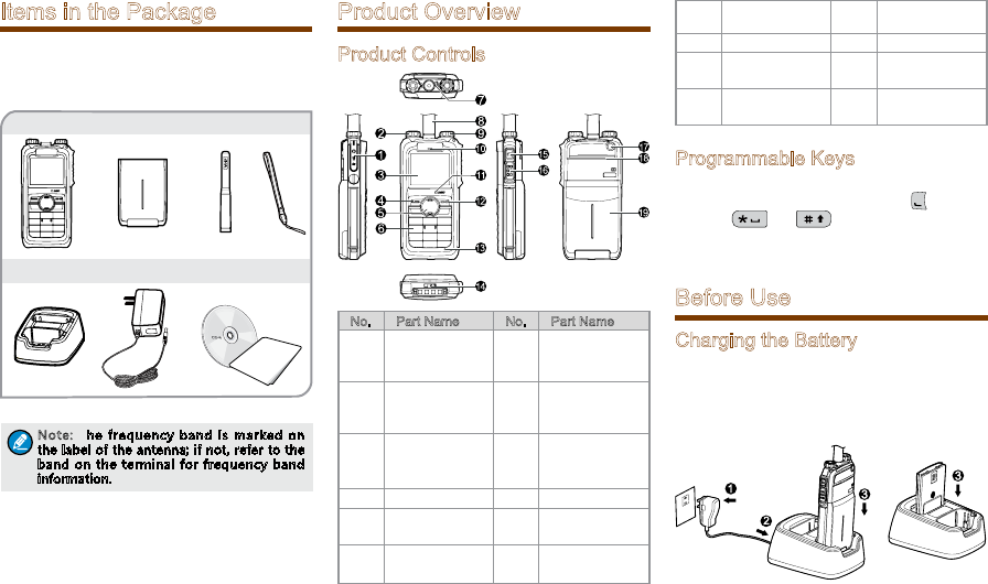
Items in the Package
Please unpack carefully and check that all items
listed below are received. If any item is missing or
damaged, please contact your dealer.
Note: The frequency band is marked on
the label of the antenna; if not, refer to the
band on the terminal for frequency band
information.
Portable Terminal Battery Antenna Strap
Charger Power Adapter Documentation Kit
Product Overview
Product Controls
No. Part Name No. Part Name
1Accessory
Connector 11
Half-
duplex Call
Microphone
2
Power On-
Off/Volume
Control Knob
12 Options/Back
Key
3 LCD Display 13
Full-
duplex call
Microphone
4 Func/OK Key 14 Battery Latch
5Navigation
Key 15 Mode Switch/
Hand-free Key
6Numeric
Keypad 16 PTT (Push-To-
Talk) Key
7 LED Indicator 17 Emergency
Key
8 Antenna 18 Speaker
9Group
Selector Knob 19 Battery
10 Full-duplex
Receiver / /
Programmable Keys
To derive enhanced convenience, you can request
your dealer to set the navigation key, , numeric
keys 1-9, and as the shortcuts to needed
functions and menus. For detailed introduction,
please refer to the corresponding TETRA Terminal
Series Feature Book.
Before Use
Charging the Battery
Only use the charger and battery specified by the
Company. The charger LED will indicate the charging
process. The figure below shows you how to charge
the battery.
OWNER'S MANUAL
3
The charger LED indicates you the charging process.
When the charger LED glows red, the charging
begins. When charging is complete, the charger LED
glows green.
The table below shows you the details.
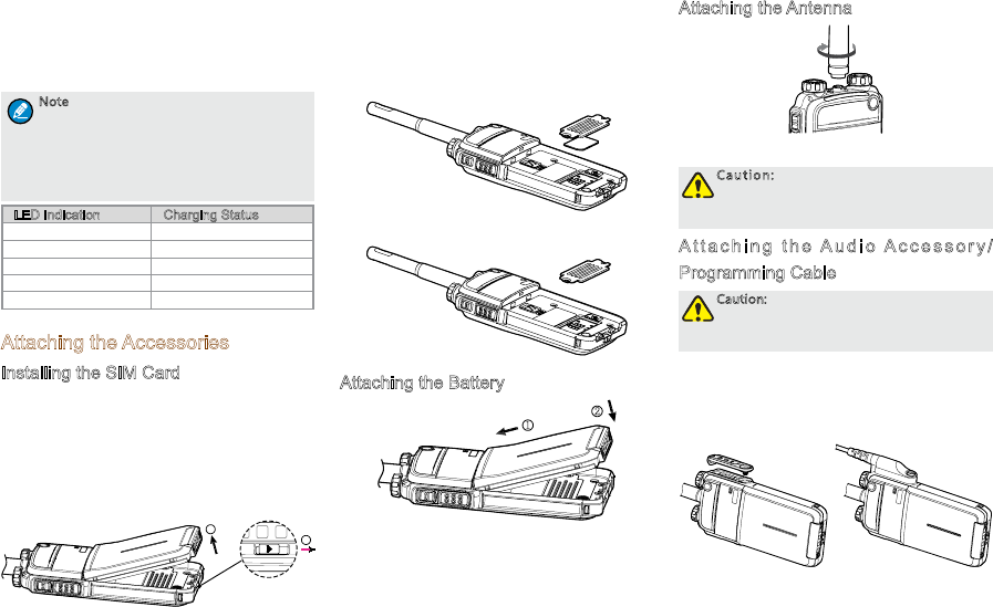
Note
●To achieve optimal battery performance,
please charge the battery for 5 hours
before initial use.
●Please refer to the Safety Information
Booklet for the detailed information on
battery use.
LED Indication Charging Status
Flashes red slowly Standby(no load)
Glows red Charging
Glows orange. 90% charged
Glows green Fully charged
Flashes red rapidly Charging failed
Attaching the Accessories
Installing the SIM Card
If a SIM card is required to realize the End-to-
End Encryption (E2EE) feature which should be
purchased separately, please install the SIM card
first.
Step 1 Slide the battery latch in the way as the
arrow shows (see 1), and then lift the battery
from its bottom (see 2).
1
2
Step 2 Loosen the screws fixing the SIM card cover,
open the cover, and then place the card
into the slot properly, as shown in the figure
below.
Step 3 Replace the cover and tighten the screw as
shown in the figure below.
Attaching the Battery
2
1
Attaching the Antenna
Caution: Do not shake the product by
holding the antenna; otherwise the work
performance and lifespan of the antenna
will be lowered.
A t t a c h i n g t h e A u d i o A c c e s s o r y /
Programming Cable
Caution: The audio accessory/programming
cable should be attached properly;
otherwise the waterproof performance of
the product will be affected.
Step 1 L o o s e n t h e s c r e w o n t h e a c c e s s o r y
connector cover, and uncover the connector.
Step 2 Align the accessory plug with the product
accessory connector.
Step 3 Secure the accessory plug with screw.
4
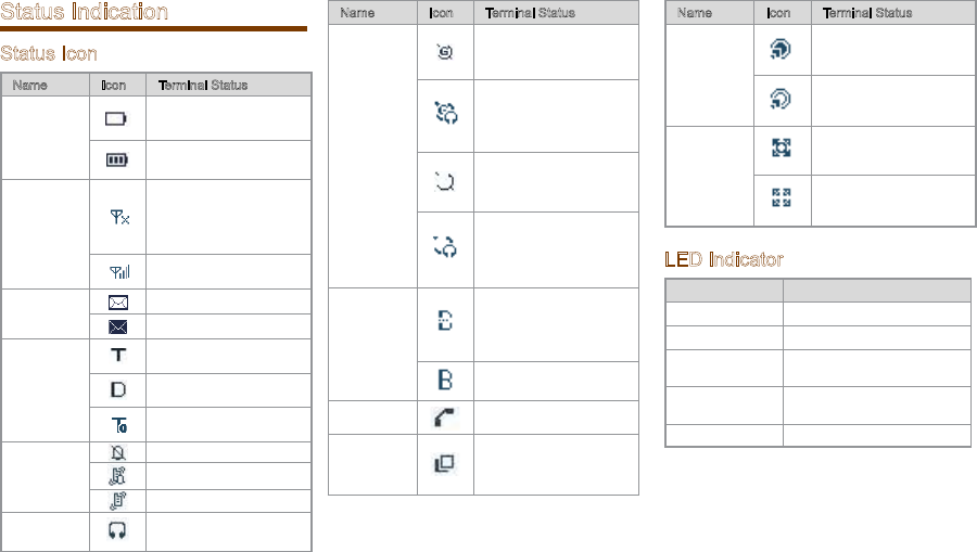
Status Indication
Status Icon
Name Icon Terminal Status
Battery
Strength
Icon
The battery strength is
low.
More bars indicate more
battery strength.
RSSI Icon
The terminal has not
registered with the
network (applicable for
TMO only).
More bars indicate a
stronger signal.
Message
Icon
Unread message(s).
The Inbox is full.
Operation
Mode Icon
The terminal is operating
in TMO.
The terminal is operating
in DMO.
The terminal is operating
in fallback mode.
Profile
Icons
Silent
Normal
Vibration
Accessory
Icon
The audio accessory is
connected.
Name Icon Terminal Status
GPS Icon
A GPS module is
connected and the valid
GPS data is received.
Valid GPS data can be
received, and the audio
accessory has been
connected.
A GPS module is
connected and no valid
GPS data is received.
No valid GPS data can
be received, and the
audio accessory has
been connected.
BT Icon
The BT feature is
enabled but the product
is not connected to BT
device.
The product is
connected to BT device.
Call Icon A call is in progress.
Group
Selection
Icon
Select a talkgroup.
Name Icon Terminal Status
Gateway
Icon
A gateway device is
available and connected
in DMO.
A gateway device
is available but
unconnected in DMO.
Repeater
Icon
A repeater is available
and connected in DMO.
A repeater is available
but unconnected in
DMO.
LED Indicator
LED Indication Terminal Status
Glows red Transmitting
Glows green Receiving
Flashes green
slowly Channel free in TMO
F l a s h e s b l u e
slowly Channel free in DMO
Glows orange. Channel busy in DMO
5
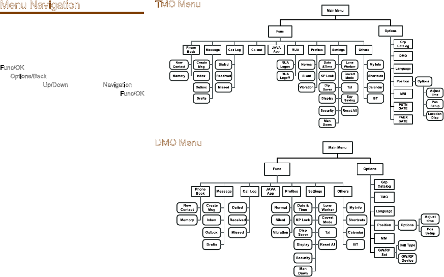
Menu Navigation
The following menu lists show the full menus of
the terminal in TMO and DMO. You can select your
needed menus to be displayed via your dealer. To
select and confirm the options in the menu, operate
as follows: in the home screen, you can press the
Func/OK key to enter the “Func” menu, or press
the Options/Back key to enter the “Options” menu;
then press the Up/Down key on the Navigation key
to select the needed menu, finally press the Func/OK
key. In sections introducing operations, a menu path
is provided for your convenience, e.g. Message ->
Create Msg.
TMO Menu
DMO Menu
6
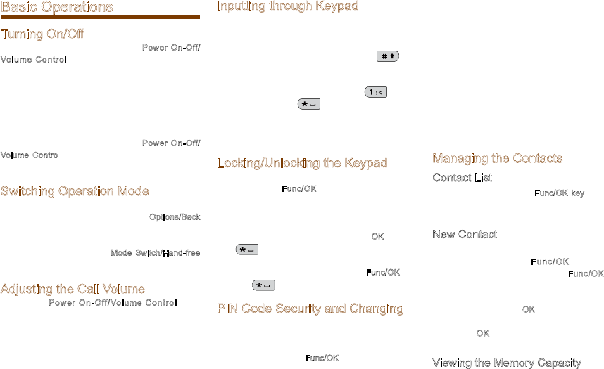
Basic Operations
Turning On/Off
To turn on the terminal, rotate the Power On-Off/
Volume Control knob clockwise. Then the LED
indicator flashes green, and the terminal shows the
power-up screen and sounds power-up alert. Upon
successful powering on, the terminal enters the home
screen. In TMO, after being turned on; the terminal
will register with the network. In DMO, the terminal
will be ready for use after being turned on.
To turn off the terminal, rotate the Power On-Off/
Volume Control knob counter-clockwise until a click
is heard.
Switching Operation Mode
This terminal can operate in either TMO or DMO. To
switch the operation mode, press the Options/Back
key in the home screen to enter the “Options”
menu, and then select “TMO” or “DMO”. Or, in
the home screen, press the Mode Switch/Hand-free
Key.
Adjusting the Call Volume
Rotate the Power On-Off/Volume Control knob
clockwise to increase the call volume, or counter-
clo ck wis e to dec re ase t he vo lum e. Aft er th e
adjustment, the terminal will save the settings and
return to the former screen automatically.
Inputting through Keypad
You can use the numeric keypad to enter user
alias and number, edit messages, etc. The terminal
supports these input methods: English and Number.
To switch the input method, press the key
on the numeric keypad. In English/Number input
method, you can enter special charac ters and
common punctuations by pressing , enter
“*” by pressing and enter a space by
long pressing this key. As for other language input
methods (depending on your customization), operate
accordingly.
Locking/Unlocking the Keypad
To enable the keypad lock, enter the Function menu
by pressing the Func/OK key in the home screen,
and then go to “Settings - > KP Lock -> On”.
After this feature is enabled, keypad will get locked
automatically when the preset time (preset by the
dealer) expires. Then you can press the OK key and
then to unlock the keypad.
Apart from locking the keypad via menu, you can lock
the keypad manually by pressing the Func/OK key
and then directly on the home screen.
PIN Code Security and Changing
PIN code can prevent unidentified user from using
your terminal. To enable or disable the PIN Code
feature, enter the Function menu from the home
screen by pressing the Func/OK key , and then go to
“Settings -> Security -> PIN Code”. Every time you
need to change the settings, it is required to input the
PIN code first (default PIN code: 1234, preset by the
dealer).
With this feature enabled, you will need to enter the
correct PIN code prior to operating the terminal after
turning it on. If you input the wrong code for 3 times
(predefined by the dealer) in a row, the terminal will
be locked. Then you will need to enter the correct
PUK code (default PUK code: 12345678) to reset the
PIN code.
To change the PIN code, go to “Settings -> Security
-> ChangePIN”, and input the correct current PIN
code prior to changing the code.
Managing the Contacts
Contact List
To view the list, press the Func/OK key to enter the
Function menu and then go to the “PhoneBook”
menu.
New Contact
To add a new contact, you can enter the Function
menu by pr essing the F unc/OK key a nd go to
“PhoneBook”. Then press the Func/OK key to
enter “Options -> New Contact” to add a new
contact: enter the contact’s alias in the editing
screen, and press the OK key to enter the “Input
No.” screen to input the contact number. At last,
press the OK key aga in to select the cal l type
(“Private No.”, “PABX” or “PSTN”).
Viewing the Memory Capacity
To view the memory capacity, you can enter the
7
Func menu by pressing the Func/OK key, and go to
“PhoneBook” menu; then press Func/OK to enter
“Memory”.
Using BT Device
As soon as the product gets successful connection
to the BT device, the audio signal will be transmitted
via the BT device instead of the microphone and
speaker of the product.
Caution:
●To derive the optimum audio quality,
you should use BT devices specified by
The Company: wireless headset, wireless
remote speaker microphone and wireless
finger PTT. For the details, please refer to
Chapter 12. Refer to the corresponding
manual for the detailed operations of the
BT devices.
●If used with other company’s BT
earpiece, the product must connect to
the wireless finger PTT specified by the
Company. Otherwise, the audio will not
be transmitted via the BT earpiece.
Do place the product in the way described below;
otherwise, the audio quality will be lowered.
●When wearing the product, be sure to wear it on
the same side with the BT devices and its LCD
display faces outwards.
●If the product is not with you, be sure that the
distance between it and the BT device is within
10 meters and its LCD display faces the BT
device.
You are recommended to connect the product to the
BT device in the ways below:
Initial Connection
Step 1 Enable the BT feature: press the shortcut
key; or go to “Func -> Others -> BT ->
Switch”. The icon will appear in the
status bar with the feature enabled.
Note: The BT PTT and the earpiece are to be
connected in the same way separately. Here
we take how to connect the BT PTT as an
example.
Step 2 Turn on the BT device and set it in connection
mode. Please refer to the corresponding
manual for detailed operations.
Step 3 Search for the PTT: go to “Func -> Others
-> BT -> Match -> PTT Search”, the product
will search for the BT PTT.
Step 4 Se le ct “S to p” w he n th e pr od uc t h as
searched the PTT.
Step 5 Connect to the BT PTT: go to “Options
-> Connect”. After getting connected, the
product LCD display goes from “Connecting
…” to connected interface with the in
the status bar.
Non-initial Connection
I f a B T d e v i ce is u p t o t h e t w o c o n d i t ions:
once connected to and reserved in the Device
L ist ( u nde r t he m e nu F unc - > O the r s - > B T
-> Ma tch ), it is re ady fo r connect ion. You ca n
select the BT d evice from the Device List an d
try connecting. If the connecting is failed, please
do the operati ons stated i n Initial Con nection.
Moreover, if the product powers off without the BT
feature disabled, the BT feature will be enabled
automatically upon the product power-on next time.
And if the once connected BT device is powered on,
it will automatically connect to the product.
Note: The Device List will be updated as
long as you perform “PTT Search” or “EP
Search”.
Enabling/Disabling Covert Mode
The covert mode is applied to conceal the product
from being discovered. When the product is in covert
mode, there will be no audible or visible indication,
such as no indicators or no LCD backlight, and the
terminal will enter silent mode or vibration mode
(which is preset by the dealer).
Note: If the product in covert mode has
been connected to an audio accessory, the
audio signal can only be transmitted via the
audio accessory.
●Enable the covert mode: press the
shortcut key, or go to “ Func -> Settings
-> CovertMode”.
●Disable the covert mode: first press Func/
OK key and then press .
8
Call Services
TMO
Individual Call
In TMO mode, an individual call can be initiated either
as a half-duplex call or full-duplex call, which can be
received without pressing any key (Direct Signaling)
or by pressing or PTT (Hook Signaling). Contact
your dealer for such programming as well as more
details.
Initiating an Individual Call
●Via Menu
In the home screen, press Func/OK key to enter
the “PhoneBook” or “Call Log” submenu,
and select a contact. Then press PTT to initiate
a half-duplex call, or press to initiate a full-
duplex call.
●Via Manual Dial
In the home screen, to initiate a half-duplex
individual call, input the number you want to
call through the keypad, and then press PTT.
To initiate a full-duplex individual call, input the
number you want to call through the keypad,
and press repeatedly to select the call type
“Private No.”. Then press to initiate a full-
duplex call.
Note:
●Entry of individual numbers must comply
with the SSI&TSI dialing rules. See
“SSI&TSI Dialing Rules” in “Appendix”
for more details.
●Calls will end automatically if the
predefined call timer expires.
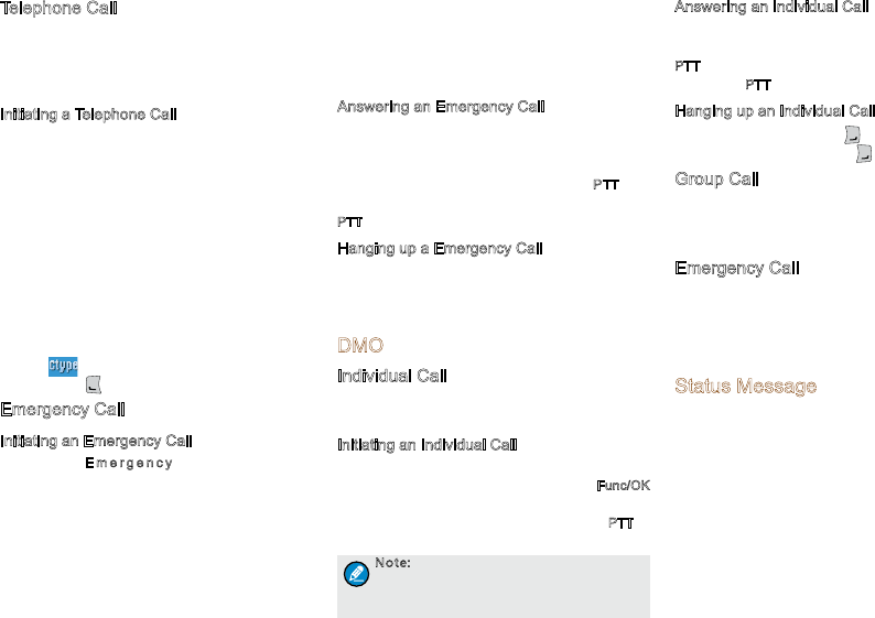
Answering an Individual Call
●Half-duplex Individual Call
»If it is an incoming call with Direct Signaling,
there will be an alert tone to inform the called
party that a call is received.
»If it is an incoming call with Hook Signaling,
the terminal sounds alert and vibrates to
in form the ca lled pa rt y t hat t here is a n
incoming call. And to receive the call, the PTT
or Func/OK key should be pressed.
To take the talk rights during the call, there
are two situations:
1) If you have no pre-emptive priority, hold
down PTT to talk after the talking party stops
talking and releases its PTT;
2) If you have already been programmed with
pre-emptive priority, hold down PTT to talk at
any time.
●Full-duplex Individual Call
»If it is an incoming call with Direct Signaling,
there will be an alert tone to inform the called
party that a call is received.
»If it is an incoming call with Hook Signaling,
the terminal sounds alert and vibrates to
in form the ca lled pa rt y t hat t here is a n
incoming call. And to receive the call, the PTT,
Func/OK key or should be pressed.
After the call is established, both parties can talk
at any time, with no need to use any key.
Hanging up/ Rejecting an Individual Call
W h e n i n i t i a t i n g t h e i n d i v i d u a l c a l l , p r e s s
t he O pti o n s/B a c k k e y o r t o t e r min a t e i t .
In the presence of an incoming individual call,
press the O ptions/B ack ke y o r to rejec t it.
In the process of an individual call, any party can
press to terminate it.
Group Call
Initiating a Group Call
In the home screen, you can initiate a group call
to the default group by pressing PTT. To call other
groups, please do as follows:
Step 1 In the home screen, rotate the Group Call
Selector knob to select a group. Please
perform this step as soon as the icon
appears; otherwise, you may fail to select.
Step 2 Press the Func/OK key to confirm your
selection.
Step 3 Press PTT to initiate a group call to this
group.
Answering a Group Call
You can receive a group call without any operation.
To take the talk rights during the call, there are two
situations:
1) if you have no pre-emptive priority, hold down
PTT to talk after the talking party stops talking and
releases its PTT;
2) if you have already been programmed with pre-
emptive priority, hold down PTT to talk at any time.
Hanging up a Group Call
The calling party can press to exit a group call.
And for the called parties in a group call, only those
enabled with “Hang Up” feature (programmable by
the dealer) can press to exit a group call. )
9
Telephone Call
The telephone call is a full-duplex individual call with
Hook signaling. To initiate the call, follow the steps
below. To answer or hang up/reject the call; see the
“Individual Call” in “TMO”.
Initiating a Telephone Call
Step 1 Select a gateway. On the home screen,
press Options/Back key to enter the “PSTN
GATE” o r “PAB X G ATE” su bme nu .
Select an appropriate gateway, and press
Func/OK key to confirm.
Step 2 Input a telephone number. Return to the
hom e s c ree n. I np u t a PA B X o r P S TN
number, which is composed of a pr efi x
(specified by the gateway, please contact
the system administrator) and the telephone
number of the target contact.
Step 3 Select a call type. Select “PABX” or “PSTN”
through the Func/OK key with a screen-label
.
Step 4 Press to initiate the call.
Emergency Call
Initiating an Emergency Call
P r e s s t h e E m e r g e n c y k e y a n d y o u c a n
ini ti ate an eme rg enc y c al l t o t he pre de f in ed
contact. Any individual contact, group contact,
d e f a u l t g r o u p , P S T N o r PABX co n t a c t c a n
b e pr e d e f i n e d a s t h e e m e r g e n c y c o n t a c t .
There are two levels for emergency call: emergency
priority and pre-emptive priority 3, which can be
programmed by your dealer. The emergency priority
is endowed with the higher privilege; thus a call
with such priority can break any other call with
pre-emptive priority 3, as well as calls with lower
priorities.
Answering an Emergency Call
The emergency call is always received automatically.
During an emergency call, the calling party can talk
with no need to use any key. If another member
needs to talk, he/she should hold down PTT only
after the calling party stops talking and releases its
PTT.
Hanging up a Emergency Call
See the corresponding part of “Individual call” or
“Group call” in accordance with the call type of the
predefined contact.
DMO
Individual Call
In DMO mode, an individual call can be initiated only
as a half-duplex call.
Initiating an Individual Call
In the home screen, directly input the number you
want to call through the keypad, or press Func/OK
key to enter the “PhoneBook” or “Call Log”
submenu, and select a contact. Then press PTT to
initiate the call.
Note: Entry of individual numbers must
comply with the SSI&TSI dialing rules. See
“SSI&TSI Dialing Rules” in “Appendix”
for more details.
Answering an Individual Call
Yo u ca n re c e i v e a n i n d i v i d ual ca l l i n D M O
automatically. During the call, you can hold down
PTT to talk after the initiating party stops talking and
releases its PTT.
Hanging up an Individual Call
The calling party can press to terminate the call.
And the called party can press to exit the call.
Group Call
Group calls in DMO mode is the same as that in TMO
mode. Please refer to operation method described in
“Group Call” in the above “TMO” section.
Emergency Call
In DMO mode, emergency calls are endowed with
emergency priority only. Please refer to operation
method described in”Emergency Call” in the
above “TMO” section.
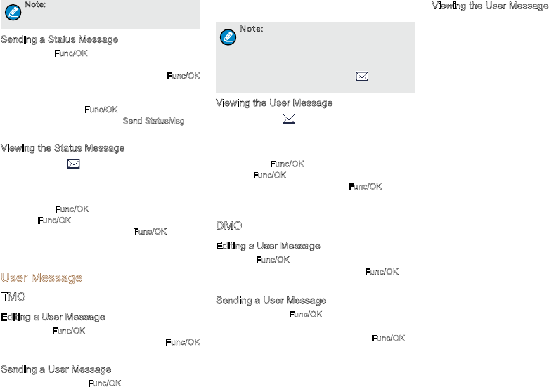
Status Message
Status message, which should be programmed by
your dealer only, can facilitate instant messaging of
the frequently-used messages. You can only send
or view rather than edit the status messages. When
the message is sent successfully, for the receiving
terminal, it will receive either the status ID of the
status message (if the terminal has not predefined
the message text) or the predefined text of the status
ID (if the terminal has predefined the message text).
10
Note: The Send StatusMsg function and the
status message are predefined by the dealer
via the CPS.
Sending a Status Message
●Press the Func/OK key and go to “Message ->
Create Msg -> StatusMsg -> Sel Msg”. Select a
desired status message, and press the Func/OK
key to proceed. Choose either an individual or a
group as the target contact, input the appropriate
number and press Func/OK to send the message.
●Long press the programmed Send StatusMsg key
to send the preset status message directly.
Viewing the Status Message
When the icon appears in the status bar, it
indicates there is/are unread message(s). Do as
follows to view it:
●In the prompt screen for an unread message,
press the Func/OK key to enter the Inbox, and
press Func/OK key again to read.
●In the home screen, press the Func/OK key and
navigate to “Message -> Inbox -> Inbox”. Then
you can view the unread message.
User Message
TMO
Editing a User Message
●Press the Func/OK key and navigate to “Message
-> Create Msg -> User Msg”. Press Func/OK
key again to edit a user message.
Sending a User Message
●After editing, press Func/OK key to confirm. Then
select the target contact and decide whether to
send it as a flash message.
Note: If the message is sent as a flash
message, the receiving party can preview
all the content in a predefined time period
without any operation. Once the time period
expires, the terminal will go back to the
former screen, with the icon displaying
on the status bar.
Viewing the User Message
When the icon appears in the status bar, it
indicates there is/are unread message(s). Do as
follows to view it:
●In the prompt screen for an unread message,
press the Func/OK key to enter the Inbox, and
press Func/OK key again to read.
●In the home screen, press the Func/OK key and
navigate to “Message -> Inbox -> Inbox”. Then
you can view the unread message.
DMO
Editing a User Message
Press the Func/OK key and navigate to “Message
-> Create Msg -> User Msg”. Press Func/OK key
again to edit a user message.
Sending a User Message
After editing, press Func/OK to confirm. Then choose
either an individual or a group as the target contact,
input the appropriate number and press Func/OK to
send the message.
Viewing the User Message
Ope r ate i n t h e s a me w ay a s t h at d esc r ibe d
in”Viewing the User Message” in the above “TMO”
section.
11
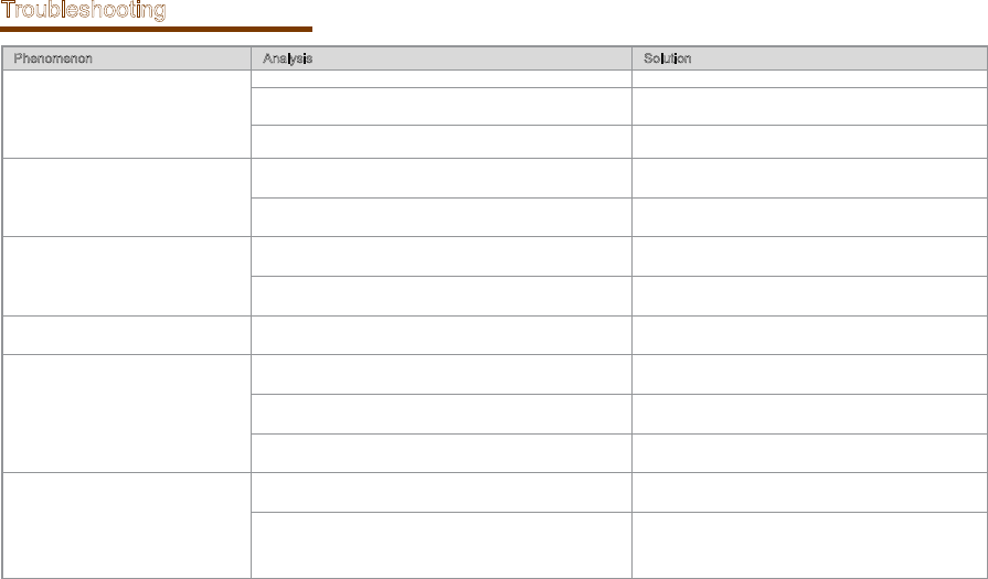
Troubleshooting
Phenomenon Analysis Solution
Network registration fails or network
can not be found.
The terminal may be operating in DMO. Switch to TMO mode.
The terminal may get out of the network coverage (in TMO
mode).
Check the signal strength. Make sure the terminal is
within the network coverage.
The terminal may not be granted network access. C ont a ct t h e n e twor k ope r a tor f o r t h e t e r min a l
authorization.
Calls cannot be initiated.
The terminal or the called party may not be within the
network coverage.
Check the signal strength. Make sure the terminal is
within the network coverage.
The terminal may operate in an improper mode. Check the operation mode. Make sure the terminal
works in the right mode.
A certain group call can not be initiated
or received.
The terminal may not be a member of the group. Check whether the terminal is a member of the group. If
not, contact your dealer to add the terminal to the group.
The terminal may not be authorized to access the target
group.
C ont a ct t h e n e twor k ope r a tor f o r t h e t e r min a l
authorization.
Calls are always interrupted. The current channel is assigned to emergency calls or other
calls with higher priority. Wait until the channel becomes available and try again.
A h a l f - d u p l e x c a l l c a n n o t b e
established.
The predefined time period for establishing a call may expire. Make sure the call is established within the predefined
time period.
The channel may be occupied by another terminal with
higher call priority. Wait until the channel becomes available and try again.
The channel resources may be allocated to other services
due to overloaded network. Wait until the channel becomes available and try again.
Abnormal disconnection occurs during
a call.
The terminal may get out of the network coverage (in TMO
mode).
Check the signal strength. Make sure the terminal is
within the network coverage.
The terminal might operate at an unfavorable position
where communication may be blocked by high buildings or
frustrated in the underground areas (in DMO mode).
Move to an open and flat area, and restart the terminal.

12
Phenomenon Analysis Solution
As for the same status message, the
content displayed at the receiving
party is different from that of the
sending party .
The parties have associated the same status message ID
with different contents.
Make sure the status message ID is associated with the
same content.
The BT device can not connect to the
product.
The BT device battery may be low. Charge the BT device.
The distance between the BT device and the product may be
out of 10 meters.
Be sure that the distance between the BT device and the
product is within 10 meters.
If the above solutions can not fix your problems, or you may have some other queries, please contact us or your local dealer for more technical support.
13
Care and Cleaning
To guarantee optimal performance as well as a long
service life of the product, please follow the tips
below.
Product Care
●Do not pierce or scrape the product.
●Keep the product far away from substances that
can corrode the circuit.
●Do no t ho ld t he pr od uc t by i ts a nt en na o r
earpiece cable directly.
●Attach the accessory connector cover when the
product is not in use.
Product Cleaning
Caution: Power off the product before
cleaning.
●Clean up the dust and fine particles on
the product surface and charging piece
with a clean and dry lint-free cloth or a
brush regularly.
●Use neutral cleanser and a non-woven
fabric to clean the keys, control knobs
and front case after long-time use. Do
not use chemical preparations such as
stain removers, alcohol, sprays or oil
preparations, so as to avoid surface case
damage.
●Make sure the product is completely dry
before use.
Optional Accessories
The following items are the main optional accessories
for the product, and please consult your local dealer
for more other accessories.
Caution: Use the accessories specified by
the Company only. If not, we shall not be
liable for any losses or damages arising out
of use of unauthorized accessories.
Power Supply
●BL Li-Ion Battery(1 00mAh)
●CH04L01 Portable Charger
●CHV09 Vehicle Adapter for Charger
●MCA05-X Battery Optimizing System
●MCA10 MCU
Multi-unit Rapid-rate Charger (for
Li-Ion Batteries)
Audio Accessory
●EWN08 Digital Wireless Covert Earpiece
(Flatpack Sensor)
●ESN14 Remote Earbud
●EHN20 Remote Swivel Earset
●EHN21 Remote C-Earset
●EAN22 Detachable Earset with
Transparent Acoustic Tube
●EAN21 3-Wire Surveillance Earpiece with
Transparent Acoustic Tube (Beige)
●EAN24 2-Wire Surveillance Earpiece with
Transparent Acoustic Tube (Black)
●SM26N1 Waterproof Remote Speaker
Microphone(IP67)
●SM26N2 Waterproof Remote Speaker
Microphone(IP54)
●POA47 Wireless Finger PTT
●EHW02 Wireless Earpiece With Dual-PTT
Others
●PC66 Programming Cable
●NCN009 Covert Shoulder Harness
●PCN005 Belt Clip
1401 4

14
Appendix
SSI&TSI Dialing Rules
In the TETRA system, subscribers are distinguished
by different identities. Each subscriber is assigned
with a unique short subscriber identity (SSI), which
serves a part of the TETRA subscriber identity (TSI).
And TSI is generally composed in this way: Mobile
Country Code (MCC) + Mobile Network Code (MNC)
+ SSI. To initiate an individual call, please dial the SSI
or TSI in compliance with the rules below.
●SSI Dialing
Make sure there are not more than 8 digits.
●TSI Dialing
»MNC+SSI:
1 ) I n p u t t h e M N C a s i t i s ;
2) SSI must be 8 digits long. Add 0 before the
first digit of SSI which is shorter than 8 digits.
For example, when MNC is 20 and SSI is 504,
you need to input 2000000504.
»M C C + M N C + S S I :
1) MCC must contain 3 digits. Add 0 before the
first digit of MCC which is shorter than 3 digits;
2) MNC must contain 4 or 5 digits. When the
MNC is shorter than 4 digits, add 0 before its
first digit; when it is 5 digits long, use it directly;
3) SSI must be 8 digits long. Add 0 before the
first digit of SSI which is shorter than 8 digits.
F or e xam p l e, w hen M C C i s 460, M N C
is 20 an d S SI i s 504, yo u n ee d to input
460002000000504.