Hytera Mobilfunk DIF5800 TETRA Digital Base Station User Manual DIB R5 flexibleTx Operation Manual
Hytera Mobilfunk GmbH TETRA Digital Base Station DIB R5 flexibleTx Operation Manual
Users Manual

DIB-R5 flexibleTx
Digital Integrated Base Station
Operation Manual
ACCESSNET®-T IP
90DIBR5flexibleTxOM02 - 1.2© 2016 Hytera Mobilfunk GmbH

Read the instructions thoroughly prior to performing any tasks!
Keep these instructions for reference.
Subject to change without notice. Data without tolerance limits is not binding.
ACCESSNET is a registered trademark of Hytera Mobilfunk GmbH. HYT and Hytera are registered trade-
marks of Hytera Communications Corporation Limited.
Hytera Mobilfunk GmbH
Fritz-Hahne-Straße 7
31848 Bad Münder
Germany
Telephone: +49 (0)5042 / 998-0
Fax: +49 (0)5042 / 998-105
E-mail: info@hytera.de
Internet: www.hytera-mobilfunk.com
DIB-R5 flexibleTx
2 Operation Manual 90DIBR5flexibleTxOM02 - 1.2

Table of contents
1 Notes on the document.................................................................................................. 7
1.1 Objectives of the document........................................................................................... 7
1.2 Intended audience of the document............................................................................. 7
1.3 Qualification of the personnel....................................................................................... 7
1.4 Reading and navigation aids in the document ........................................................... 8
1.5 Figures and special notations used.............................................................................. 8
1.5.1 Figures used..................................................................................................................... 8
1.5.2 Special notations.............................................................................................................. 8
1.5.2.1 Operating procedures....................................................................................................... 9
1.5.2.2 Safety instructions used.................................................................................................... 9
1.5.2.3 General instructions used............................................................................................... 10
1.5.2.4 Text formatting used....................................................................................................... 10
1.6 History of changes....................................................................................................... 11
1.7 Further applicable documents.................................................................................... 11
1.8 Support information..................................................................................................... 12
2 Safety regulations......................................................................................................... 15
2.1 Safety instructions and declaration of conformity.................................................... 15
2.1.1 Safety instructions and declaration of conformity for North America.............................. 15
2.2 Intended use.................................................................................................................. 18
2.3 Safety measures........................................................................................................... 19
2.3.1 Authorized personnel...................................................................................................... 19
2.3.2 Electromagnetic compatibility......................................................................................... 20
2.3.2.1 Electromagnetic compatibility for North America............................................................ 20
2.3.3 Notes on the electrical system........................................................................................ 20
2.3.4 Hazardous substances................................................................................................... 21
2.3.4.1 Hazardous substances outside Europe.......................................................................... 21
2.3.5 Product disposal............................................................................................................. 21
2.3.5.1 Product disposal outside Europe.................................................................................... 21
2.4 Safety and responsibility............................................................................................. 21
2.5 Safety markings............................................................................................................ 22
2.5.1 Safety markings on the product...................................................................................... 22
2.5.2 Safety markings on transport boxes............................................................................... 22
2.5.2.1 Safety marking "Fragile"................................................................................................. 22
2.5.2.2 Safety marking "Transport Upright"................................................................................ 23
Table of contents
DIB-R5 flexibleTx
3Operation Manual 90DIBR5flexibleTxOM02 - 1.2

2.5.2.3 Safety marking "Keep dry".............................................................................................. 23
3 Product description...................................................................................................... 25
3.1 Characteristics of the DIB-R5...................................................................................... 31
3.2 Components.................................................................................................................. 32
3.2.1 Connection and control panel......................................................................................... 33
3.2.1.1 On/off switch................................................................................................................... 36
3.2.1.2 Connection panel............................................................................................................ 36
3.2.1.3 GNSS splitter.................................................................................................................. 38
3.2.2 VAC power supply............................................................................................................ 38
3.2.2.1 AC Power Distribution Module (APDM).......................................................................... 38
3.2.2.2 Power Supply Unit (PSU) including Power Supply Module (PSM)................................. 40
3.2.3 VDC power supply............................................................................................................ 42
3.2.4 Divider Unit (DIU)............................................................................................................ 44
3.2.4.1 Active Divider Unit (ADU)............................................................................................... 45
3.2.5 TETRA Channel Unit (CHU)........................................................................................... 46
3.2.6 Base Station Controller Unit (BSCU).............................................................................. 49
3.2.7 Fan unit........................................................................................................................... 53
3.2.8 Backplane....................................................................................................................... 55
3.3 Interfaces....................................................................................................................... 57
3.4 Wiring diagrams............................................................................................................ 57
3.4.1 Internal wiring................................................................................................................. 58
3.4.1.1 Internal wiring with four CHUs and external antenna coupling system........................... 58
3.4.2 Antenna configurations................................................................................................... 59
3.4.2.1 Antenna configuration with four CHUs and external antenna coupling system.............. 59
3.5 Redundancy options.................................................................................................... 60
3.5.1 Redundant main control channel (MCCH)...................................................................... 61
3.5.2 Carrier redundancy......................................................................................................... 61
3.5.3 Controller redundancy.................................................................................................... 61
3.5.4 Fallback operation.......................................................................................................... 61
3.5.5 Stand-alone operation.................................................................................................... 62
3.5.6 Redundant VAC power supply......................................................................................... 62
3.5.6.1 Redundant rectifier modules (Power Supply Module, PSM)........................................... 62
3.5.6.2 Redundant power supply lines........................................................................................ 63
3.5.7 Redundant connection to the transport network............................................................. 63
3.5.8 Redundant synchronization (GNSS, PTP)...................................................................... 63
3.6 Scope of delivery.......................................................................................................... 64
4 Operation....................................................................................................................... 65
Table of contents
DIB-R5 flexibleTx
4 Operation Manual 90DIBR5flexibleTxOM02 - 1.2

4.1 Safety measures and prerequisites............................................................................ 65
4.2 Switching on the DIB-R5 flexibleTx............................................................................ 66
4.3 Function tests and operational monitoring................................................................ 67
4.3.1 Work equipment for function tests.................................................................................. 68
4.3.2 Connecting the service computer................................................................................... 69
4.3.3 Checking operating states.............................................................................................. 70
4.3.3.1 Checking operating states (via LEDs)............................................................................ 70
4.3.3.2 Checking operating states (audible check)..................................................................... 70
4.3.3.3 Checking operating states (via NMC-511 FaultManager)............................................... 71
4.3.4 Checking the availability................................................................................................. 72
4.3.5 Checking standby carriers ‒ optional.............................................................................. 73
4.3.6 Function tests and GNSS operational monitoring........................................................... 74
4.3.6.1 Checking the installation site of the GNSS antenna....................................................... 74
4.3.6.2 GNSS operational monitoring (via NMC-511 FaultManager)......................................... 75
4.3.7 Function tests and PTP operational monitoring (optional).............................................. 76
4.3.7.1 PTP operational monitoring (via NMC-511 FaultManager)............................................. 76
4.3.8 Checking external antenna coupling systems................................................................ 77
5 Service interruption...................................................................................................... 79
5.1 Shutting down hardware components....................................................................... 79
5.2 Switching off the DIB-R5 flexibleTx............................................................................ 80
6 Recommissioning......................................................................................................... 81
7 Maintenance.................................................................................................................. 83
7.1 Maintenance tasks........................................................................................................ 83
7.2 Periodical visual inspections...................................................................................... 84
8 Troubleshooting........................................................................................................... 85
9 Index.............................................................................................................................. 89
Table of contents
DIB-R5 flexibleTx
5Operation Manual 90DIBR5flexibleTxOM02 - 1.2

Table of contents
DIB-R5 flexibleTx
6 Operation Manual 90DIBR5flexibleTxOM02 - 1.2

1 Notes on the document
This chapter provides information on using the document. In addition, it specifies require-
ments that are absolutely necessary when working with the product.
1.1 Objectives of the document
The present document from Hytera Mobilfunk GmbH describes the procedures that are
required for the activities on and with the product:
nOperation
nService interruption
nRecommissioning
nMaintenance
In this context, it describes the relevant safety regulations as well as the components and
operation of the product that is used in the ACCESSNET-T IP mobile radio system.
1.2 Intended audience of the document
The present document reverts to all the persons, who:
noperate an ACCESSNET-T IP TETRA mobile radio system,
ncommission and decommission the product,
nmaintain the product.
Each person commissioned with performing the tasks mentioned above with or on the
system must have read and understood the present document and the associated
accompanying documentation.
1.3 Qualification of the personnel
Only experts are permitted to perform the tasks described in the present document. The
experts must be authorized to perform these tasks.
Experts are persons, who:
nare trained and experienced in the corresponding field.
nare familiar with the applicable standards, regulations and provisions associated with
the corresponding task.
Notes on the document
Qualification of the personnel
DIB-R5 flexibleTx
7Operation Manual 90DIBR5flexibleTxOM02 - 1.2

1.4 Reading and navigation aids in the document
As reading and navigation aids, overview tables have been provided at the beginning of
the respective chapters in the present document. These are to provide the reader with an
overview of the tasks to be performed. In addition, they indicate the order in which the
tasks are to be performed. When you have completed a work step, always navigate to the
next work step via the overview table to ensure that the tasks are performed in the correct
order. The overview tables are useful for readers of the printed document (indication of
the corresponding chapters) as well as for readers of a PDF document at the PC (via
active cross-references to the corresponding chapters).
1.5 Figures and special notations used
Figures and symbols are used in the present document. They are used to illustrate the
product and to emphasize particular pieces of information.
1.5.1 Figures used
The figures used in this document show the product, if necessary in a simplified form for
clarity (e.g. technical drawings). They refer to different product designs. If not described
otherwise, the respective figure relates to the standard product design.
1.5.2 Special notations
The special forms of notation described below are intended to make it easier to under-
stand the information. They emphasize specific pieces of information, help you to recog-
nize this information fast and take corresponding measures.
Notes on the document
Figures and special notations used > Special notations
DIB-R5 flexibleTx
8 Operation Manual 90DIBR5flexibleTxOM02 - 1.2
1.5.2.1 Operating procedures
The present document describes the tasks that have to be performed in the form of oper-
ating procedures. Standard operating procedures guide you step by step through a
sequence of actions until you have reached the desired goal.
Example of a sequence of actions:
Goal of the actions
Preparation:
nList of the prerequisite(s) for an action
n...
1. Description of the first of several work steps.
ðA possible result of the work step just performed.
2. Description of the second work step.
➔ Confirmation: Results of the entire sequence of actions.
1.5.2.2 Safety instructions used
Safety instructions in this document point to a hazard that may put persons or the
product/system at risk.
Within a safety instruction, the following items are brought to your attention:
nType of danger
nSource of danger
nMeasures to be taken to avert the specified danger
Shown below are four security advice symbols which indicate the severity of the danger
by means of different keywords (danger, warning, caution, attention). The symbols shown
may vary depending on the nature and source of the danger.
This symbol identifies security instructions
You are warned of an imminent danger for the life or health of persons.
➔ The arrow identifies a precautionary measure designed to avert this danger.
This symbol identifies security instructions
You are warned of a potential danger for the life or health of persons.
➔ The arrow identifies a precautionary measure designed to avert this danger.
Notes on the document
Figures and special notations used > Special notations
DIB-R5 flexibleTx
9Operation Manual 90DIBR5flexibleTxOM02 - 1.2
This symbol identifies security instructions
You are warned of a potentially dangerous situation for the life or health of persons.
➔ The arrow identifies a precautionary measure designed to avert this danger.
This symbol identifies security instructions.
You are warned of a danger for the product.
➔ The arrow identifies a precautionary measure designed to avert this danger.
1.5.2.3 General instructions used
General instructions provide supplementary and useful information.
Important Information
This symbol identifies information that may assist in handling and using the product.
This includes references to further information.
1.5.2.4 Text formatting used
The following table provides an overview of the text formats used and describes the sig-
nificance of these formats.
Text formatting used
Text formatting Description Example
Example Identifies components of the user
interface of software components
such as network management clients
(NMC).
Buttons, dialogs etc.
Example Identifies required inputs. Passwords, IP
addresses etc.
Example Identifies outputs. Panel outputs etc.
Notes on the document
Figures and special notations used > Special notations
DIB-R5 flexibleTx
10 Operation Manual 90DIBR5flexibleTxOM02 - 1.2

1.6 History of changes
The following table identifies the changes made to a document. The following reasons for
changes are distinguished:
nContent-related changes (e.g. functional expansions or new functions)
nEditorial changes (e.g. changes to the layout)
nFault corrections (document-specific corrections)
History of changes
Version Date Reason for
changes
Implemented changes refer to
1.1 2016-01-25 Content-
related
changes
Expansion of safety regulations
(FCC/IC)
Ä
Chapter 2 “Safety reg-
ulations” on page 15
Product description updated
Ä
Chapter 3 “Product
description” on page 25
1.2 2016-02-02 Content-
related
changes
"Model Name" updated
Ä
Table “Certified fre-
quency ranges (FCC/
IC)” on page 16
1.7 Further applicable documents
Apart from the present documentation, the scope of delivery of the product includes addi-
tional documents. In addition to the contents of the present documentation, all the other
documents associated with the product must always be taken into consideration. They
are mandatory for the use of the product. If required, revert to Hytera Mobilfunk GmbH to
request the other applicable documents.
These are:
nDIB-R5 flexibleTx Technical Data
describe the technical properties of the product.
nDIB-R5 flexibleTx Site Requirements
describe the requirements for the site where the product is used.
nDIB-R5 flexibleTx Installation Manual
describes the proper setup and electrical connection of the product at site.
nDIB-R5 flexibleTx Configuration Manual
describes the configuration of the product.
nDIB-R5 flexibleTx Service and Maintenance Manual
describes the maintenance and care of the product and the replacement of the com-
ponents installed in the product.
nRequirement Manual IP/VoIP
describes the requirements for securing the IP communication within
ACCESSNET-T IP mobile radio networks as well as outside, e.g. via VoIP telephone
systems (Voice-over-IP, VoIP).
nACCESSNET-T IP Service Computer Configuration Manual
describes the configuration of the service computer that is used for the installation
and commissioning of network constituents of the ACCESSNET-T IP as well as for
service and maintenance purposes.
Notes on the document
Further applicable documents
DIB-R5 flexibleTx
11Operation Manual 90DIBR5flexibleTxOM02 - 1.2

nUser manuals of network management clients
provides information required for proper operation of the NMCs and support trouble-
shooting.
The user manuals for the following NMCs must be observed:
–NMC-511 FaultManager
–NMC-515 ConfigurationManager
nOpen Source Acknowledgement
contains information on the respective open source software the product comprises,
including the information on the license(s) used and the related license agreements.
nACCESSNET-T IP Versions
contains information about all versions that are valid for the present PV, e.g. compo-
nent versions of software components or document versions.
nproject-specific documents e.g. the "Base Design" document, where applicable,
describe the implemented network and the associated properties and requirements.
Further applicable documents
Please also heed the documentation of the third-party devices connected to the product
to prevent negative effects or problems with product.
1.8 Support information
If you have any questions or proposals with regard to the products of Hytera Mobilfunk
GmbH, please revert to your local service partner or directly to Hytera Mobilfunk GmbH.
For a fast and cost-effective solution of any technical problems that come up during the
operation of your ACCESSNET-T IP mobile radio system, Hytera Mobilfunk GmbH offers
support contracts upon request. For information on this topic, please also revert to your
local service partner or directly to Hytera Mobilfunk GmbH.
Product training courses assist you in making use of the full scope of features and capa-
bilities of your ACCESSNET-T IP mobile radio system. For information on the training
program of Hytera Mobilfunk GmbH, please revert to our responsible service partner, to
your local Hytera branch office or directly to Hytera Mobilfunk GmbH.
Hytera Mobilfunk GmbH
Fritz-Hahne-Straße 7
31848 Bad Münder
Germany
Telephone: +49 (0)5042 / 998-0
Fax: +49 (0)5042 / 998-105
E-mail: info@hytera.de
Internet: www.hytera-mobilfunk.com
Notes on the document
Support information
DIB-R5 flexibleTx
12 Operation Manual 90DIBR5flexibleTxOM02 - 1.2

2 Safety regulations
This chapter describes the safety regulations relevant for using the product
DIB-R5 flexibleTx.
2.1 Safety instructions and declaration of conformity
The operation of the product is subject to the statutory provisions of the respective
country, in which the product is used. For the operation, the required operating licenses
must be requested from the responsible local authorities. Particularly the frequency range
used must be reserved for the respective purpose in the country, in which the product is
used. The product user is responsible for complying with the statutory provisions and the
intended use.
2.1.1 Safety instructions and declaration of conformity for North America
The product complies with the requirements of the Federal Communications Commission
(FCC).
This device complies with part 15 and 90 of the FCC Rules. Operation is subject to the
following two conditions:
nThis device may not cause harmful interference, and
nthis device must accept any interference received, including interference that may
cause undesired operation.
Changes or modifications not expressly approved by the party responsible for compliance
could void the user's authority to operate the equipment.
The product complies with the requirements of ICES-003 Issue 5 and RSS-119 of
Industry Canada (IC).
Le présent appareil est conforme aux CNR d'Industrie Canada applicables aux appareils
radio exempts de licence. L'exploitation est autorisée aux deux conditions suivantes :
nl'appareil ne doit pas produire de brouillage, et
nl'utilisateur de l'appareil doit accepter tout brouillage radioélectrique subi, même si le
brouillage est susceptible d'en compromettre le fonctionnement.
This device complies with Industry Canada license-exempt RSS standard(s). Operation is
subject to the following two conditions:
nThis device may not cause interference, and
nthis device must accept any interference, including interference that may cause unde-
sired operation of the device.
Safety regulations
Safety instructions and declaration of conformity > Safety instructions and declaration of conformity for North America
DIB-R5 flexibleTx
13Operation Manual 90DIBR5flexibleTxOM02 - 1.2

Operation of the product in North America
The product is certified for operation on the territory of the United Sates of America and
of Canada by the Federal Communications Commission (FCC) as well as by Industry
Canada (IC). It may only be operated in the certified frequency ranges and at the fre-
quencies approved at the sites concerned.
The FCC and IC has approved the DIB-R5 for the USA and/or Canada for the frequency
ranges listed in the table below.
Certified frequency ranges (FCC/IC)
Authority Model Name FCC Identifier/Cer-
tification Number
Frequency range
(MHz)
Federal Communi-
cations Commission
(FCC)
DIF-R5400 ZW4DIF5400 450,0 to 470,0
DIF-R5800 ZW4DIF5800 854,0 to 869,0
Industry Canada
(IC)
DIF-R5400 4431B-DIF5400 n406,1 to 430,0
n450,0 to 470,0
DIF-R5800 4431B-DIF5800 851,0 to 869,0
Further information on the certifications is available on the websites of the FCC and the
IC:
nFCC: http://www.fcc.gov/
nIC: http://www.ic.gc.ca/
The product meets the requirements of FCC and IC for the United States and Canada,
respectively, only if the external antenna coupling system meets all requirements at all
times, refer to
Ä
Table “Requirements for external antenna coupling systems” on
page 15.
Responsibility for the installation, commissioning and maintenance of the external
antenna coupling system
The network operator is responsible for the proper installation, commissioning and main-
tenance of external antenna coupling systems unless this is an integral part of the con-
tract with the Hytera Mobilfunk GmbH. An installer who may have been entrusted with
the installation/commissioning and/or maintenance of the antenna coupling system is
responsible for complying with all the applicable requirements and for the metrological
tests required afterwards.
The network operator is responsible for ensuring that:
–all of the requirements listed in the following are met at any time.
–equipment for overload protection and lightning protection has been provided at the
installation site.
Safety regulations
Safety instructions and declaration of conformity > Safety instructions and declaration of conformity for North America
DIB-R5 flexibleTx
14 Operation Manual 90DIBR5flexibleTxOM02 - 1.2

The following table describes the requirements for external antenna coupling systems.
Requirements for external antenna coupling systems
Component Property/demand Value/value range
Transmitter coupling
system
Return loss at all Tx inputs ≥ 19 dB
Isolation between Tx inputs ≥ 50 dB
between output and Tx
inputs
≥ 50 dB
Impedance at all Tx inputs 50 Ω
Input power per Tx input (mean value) according to the adjusted
transceiver power
Input power (total, mean value) according to the total of
the adjusted transceiver
power
Input power (total, peak value) (log2 (number of trans-
ceivers) +1) x 3 dB +
output per transceiver
[dB]
Intermodulation products
of 3rd order (IM 3)
between Tx inputs
2 x 49 dBm @ 250 kHz > 85 dB
Intermodulation products
of 3rd order (IM 3) per Tx
input
2 x 47 dBm @ 10 kHz > 65 dB
Duplex filter (with
common Tx/Rx antenna)
Isolation between Tx and
Rx input
common Tx/Rx antenna:
0 dB antenna decoupling
≥ 80 dB
Intermodulation products
of 3rd order (IM 3)
2 x 46 dBm @ 250 kHz ≤ -150 dBc
Input power (total, peak value) according to the total
output from the trans-
mitter coupling system
Suppression of 2nd harmonic of all transmitters > 30 dB
Transmitting filter Attenuation in Rx band Separate Tx/Rx
antennas, assumed
antenna decoupling
25 dB
≥ 55 dB
Intermodulation products
of 3rd order (IM 3)
2 x 46 dBm @ 250 kHz ≤ -150 dBc
Input power (total, peak value) according to the total
output from the trans-
mitter coupling system
Safety regulations
Safety instructions and declaration of conformity > Safety instructions and declaration of conformity for North America
DIB-R5 flexibleTx
15Operation Manual 90DIBR5flexibleTxOM02 - 1.2

Component Property/demand Value/value range
Receiving filter Attenuation in Tx band Separate Tx/Rx
antennas, assumed
antenna decoupling
25 dB
≥ 55 dB
Attenuation ≤ 1.2 dB to achieve the
sensitivity according to
the Technical Data
2.2 Intended use
The product is exclusively designed for being used as a professional TETRA base sta-
tion. In this application it is used for the wireless communication between subscribers
equipped with the corresponding terminals as well as for switching calls and transferring
data between subscribers within a TETRA (Terrestrial Trunked Radio) network.
Intended use also includes that:
nall the security instructions set forth in the product documents are always heeded,
nall the maintenance tasks described are performed in the interval specified,
nthe general, national and in-house safety regulations are heeded.
Any other use is impermissible.
The product is not used as intended, for example, if:
nthe requirements described in the product documents haven't been met and instruc-
tions are disregarded,
nthe product is modified structurally or technically without the approval of Hytera Mobil-
funk GmbH,
nreplacement parts are used that differ from the components installed by default.
The network operator of the product is responsible for damage to the product or damage
caused by the product if the product was used beyond the intended application range
and/or was not used as intended.
The network operator is responsible for ensuring that:
nthe product is used exclusively within the scope of the intended use,
nwork on the electrical installation is performed only by experts that have been trained
accordingly,
nspecial legal requirements that govern the operation of the product are complied with,
nproduct modifications or expansions:
–are performed only after having consulted Hytera Mobilfunk GmbH,
–are only performed in compliance with the state of the art and scientific knowl-
edge,
–are performed taking into consideration the applicable national and international
provisions,
–are performed exclusively by trained experts who have been authorized accord-
ingly.
ndamage to the product and product defects are immediately remedied by experts that
have been trained and authorized accordingly,
Safety regulations
Intended use
DIB-R5 flexibleTx
16 Operation Manual 90DIBR5flexibleTxOM02 - 1.2

nappropriate measures are taken against radio interference,
nany defects in the operation room that come up later on are eliminated immediately,
nfor subsequent modifications of the operation room, the requirements described in the
present document are always taken into consideration,
nappropriate fire precautions are taken as required (e.g. the use of appropriate fire
extinguishers),
nspecial legal requirements that control the operation and handling of batteries and
battery systems, if used, are complied with and that appropriate security devices and
measures are provided and taken as required.
Country-specific laws and provisions
All the stipulated laws and provisions of the respective country of use shall always
apply. The network operator is responsible for the adherence to these laws and provi-
sions.
2.3 Safety measures
All the regulations specified in the following must be adhered to without fail:
nIf extension cables or multiple socket outlets are used, make sure that they are
inspected for proper condition periodically.
nAfter any security-related parts have been replaced (e.g. power switch or circuit
breakers) a security check must be performed (visual inspection, protective conductor
load, leakage resistance, leakage current measurement, function test).
nObserve other task-related security measures and requirements in the standard oper-
ating procedures.
Heed the security labeling!
In addition to the safety notices described within the product documentation, all safety
labels attached in and on the product must be observed. They point out potential haz-
ardous areas and must neither be removed nor changed.
2.3.1 Authorized personnel
The product may only transported, set up/installed, connected, commissioned, operated
and maintained by experts who know and follow the respective valid safety and installa-
tion regulations.
The experts must be authorized to perform the required tasks by the person responsible
for the security in the enterprise of the network operator. This aspect includes ensuring
that access to the site is safeguarded and instruction has been provided on all precau-
tionary measures to be taken.
Safety regulations
Safety measures > Authorized personnel
DIB-R5 flexibleTx
17Operation Manual 90DIBR5flexibleTxOM02 - 1.2

Experts are persons, who
nare trained and experienced in the corresponding field,
nare familiar with the relevant standards, regulations, provisions and security codes,
nhave been instructed in the mode of operation and the operating conditions of the
equipment components,
ncan identify and avert dangers.
Depending on the tasks to be performed, the following user groups are distinguished:
nOperators: Persons who
–operate the product,
–monitor, interrupt, terminate and restore operation of the product.
nService personnel: Persons who
–set up the product,
–prepare and restore the operational state,
–adjust and/or parameterize the product,
–monitor, interrupt, terminate and restore operation of the product,
–maintain, care for, and repair the product.
2.3.2 Electromagnetic compatibility
For function-related reasons, increased electromagnetic radiation may occur with specific
products, e.g. RF radio systems. Taking into consideration that unborn life is increasingly
worthy of being protected, pregnant women should be protected through appropriate
measures. People with personal medical devices such as cardiac pacemakers and
hearing aids can also be endangered by electromagnetic radiation. The network operator
is obliged to assess workplaces with a considerable risk of exposure to radiation and to
avert any hazards.
2.3.2.1 Electromagnetic compatibility for North America
For compliance with the electromagnetic radiation and the limit values with regard to the
security of the general population in high-frequency fields, the document "RF Exposure"
must always be observed. For the proper operation of the product, the limit values speci-
fied in the document "RF Exposure" must always be complied with. For this purpose, site-
specific calculations by the network operator may be required.
The document "RF Exposure Info" is available at the following URL as a PDF file:
https://apps.fcc.gov/oetcf/eas/reports/GenericSearch.cfm.
For this purpose, the first three digits of the FCC Identifier must be entered on the form as
"Grantee Code" (ZW4) and the remaining digits as "Product Code", refer to
Ä
Table “Cer-
tified frequency ranges (FCC/IC)” on page 14.
2.3.3 Notes on the electrical system
The product may be operated only in the operational states specified by the manufacturer
without impairment of the ventilation.
Safety regulations
Safety measures > Notes on the electrical system
DIB-R5 flexibleTx
18 Operation Manual 90DIBR5flexibleTxOM02 - 1.2

Make sure that all the security measures on the equipment, on the connecting cables and
on the load have been taken. Electrical connections may be made/disconnected only
when neither voltage nor current is applied to the equipment. Voltage may still be present
on the outputs of the equipment after the device has been switched off.
Only perform those tasks described in the documents included in the scope of delivery of
the product.
2.3.4 Hazardous substances
The following chapters contain information on hazardous substances.
2.3.4.1 Hazardous substances outside Europe
All the stipulated laws and provisions of the respective country of use shall always apply.
The network operator is responsible for the adherence to these laws and provisions.
2.3.5 Product disposal
The following chapters contain information on product disposal.
2.3.5.1 Product disposal outside Europe
All the stipulated laws and provisions of the respective country of use shall always apply.
The operator is responsible for the adherence to these laws and provisions.
2.4 Safety and responsibility
The following chapter lists all relevant security notices for the safe handling of the
product. The listed security notices must be followed for all operations on the product.
Observing the product documentation
The product documentation is part of the product and an important component in the
security concept. Its non-observance can result in serious injuries or even death.
➔ Read the product documentation and always follow all described procedures and
warning notices.
➔ Always keep the product documentation next to the product.
➔ Pass on the product documentation to all subsequent users.
Safety regulations
Safety and responsibility
DIB-R5 flexibleTx
19Operation Manual 90DIBR5flexibleTxOM02 - 1.2

2.5 Safety markings
The following chapters describe security markings on the product and its packaging.
2.5.1 Safety markings on the product
The product is equipped with security markings. They serve as an indication to possible
hazards and may not be deleted or modified (if necessary, marking in accordance with
DIN 4844 BGV A8 [VBG 125]).
2.5.2 Safety markings on transport boxes
To protect against improper handling of the product during a transport, the transport
boxes and the product itself are fitted with corresponding security markings to call atten-
tion to proper handling.
Transport inspection using impact indicators
To check whether a product was properly transported, the transport boxes are fitted with
impact indicators. The impact indicator shows heavy impacts or vibrations that were
caused by an improper transport.
The following chapters describe the used security markings and indicate that the corre-
sponding instructions must be followed.
2.5.2.1 Safety marking "Fragile"
The security marking "Fragile" points to the necessary protection of the product against
shock. Transport boxes with this marking must absolutely be protected against shock.
Figure 1: Safety marking "Fragile"
Safety regulations
Safety markings > Safety markings on transport boxes
DIB-R5 flexibleTx
20 Operation Manual 90DIBR5flexibleTxOM02 - 1.2

2.5.2.2 Safety marking "Transport Upright"
The security marking "Transport Upright" points to the cover of the transport box. Trans-
port boxes with this marking must always be transported with the cover at the top.
Figure 2: Safety marking "Transport Upright"
2.5.2.3 Safety marking "Keep dry"
The security marking "Keep dry" points to the necessary protection of the product against
wetness (e.g. rain, high humidity during the transport in closed vehicles/containers and/or
formation of condensate when covered with a tarpaulin). Transport boxes with this
marking must absolutely be protected against any wet influences.
Figure 3: Safety marking "Keep dry"
Safety regulations
Safety markings > Safety markings on transport boxes
DIB-R5 flexibleTx
21Operation Manual 90DIBR5flexibleTxOM02 - 1.2

Safety regulations
Safety markings > Safety markings on transport boxes
DIB-R5 flexibleTx
22 Operation Manual 90DIBR5flexibleTxOM02 - 1.2
3 Product description
The DIB-R5 base station family is a constituent of the TETRA mobile radio system
ACCESSNET-T IP and ensures the powerful and reliable mobile radio coverage of a spe-
cific area. Pioneering TETRA Release 2 support, particularly the TEDS technology
(TETRA Enhanced Data Service), render the DIB-R5 extremely attractive for all scenarios
in which a high degree of availability as well as high-speed data are absolutely neces-
sary. The TEDS data transmission allows transferring up to 150 kbit/s (gross bit rate)
securely and reliably via the air interface.
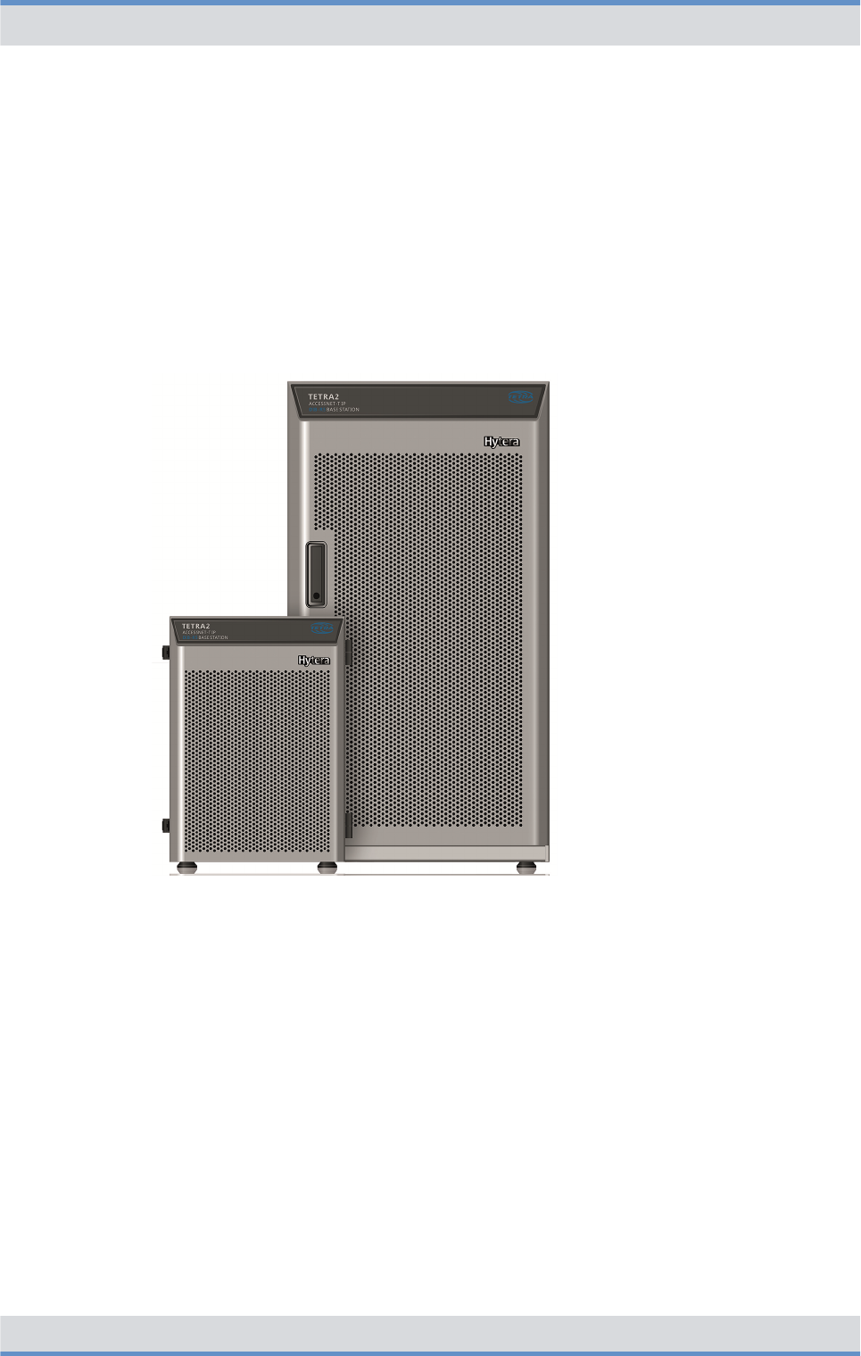
Figure 4: DIB-R5 family
The different variants of the base station family DIB-R5 meet customer and network
requirements in a perfect way. The following variants of the DIB-R5 are available:
nDIB-R5 advanced
The DIB-R5 advanced offers up to eight TETRA carriers with cavity combiner and
consists of one or two equipment racks depending on the number of carriers.
nDIB-R5 compact
The DIB-R5 compact offers up to four TETRA carriers with hybrid combiner and con-
sists of one or two compact racks depending on the number of carriers.
DIB-R5 compact is suitable for space-saving installation in existing 19" equipment
racks.
nDIB-R5 flexibleTx
The DIB-R5 flexibleTx provides up to four TETRA carriers in a compact rack and is
operated project-specific with external antenna coupling systems. DIB-R5 flexibleTx is
suitable for space-saving installation in existing 19" equipment racks.
Product description
DIB-R5 flexibleTx
23Operation Manual 90DIBR5flexibleTxOM02 - 1.2

The hardware design of DIB-R5 features a modular layout. This allows hardware compo-
nents to be replaced or added during ongoing operation.
Properties of the DIB-R5 flexibleTx
In each compact rack DIB-R5 flexibleTx offers space for four TETRA Channel Units
(CHU), which are each providing one TETRA carrier. Thus offers DIB-R5 flexibleTx a
maximum of 16 radio channels to the radio subscribers that can be used simultaneously.
To increase the availability, DIB-R5 flexibleTx can be equipped with different redundancy
options to avoid "Single Points of Failure". On the hardware side, the transceivers, control
unit and power supply can be designed redundantly. Furthermore, additional software-
based redundancy options are available that further increase the reliability of features.
DIB-R5 flexibleTx is used project-specific with external antenna coupling systems. In
addition, DIB-R5 flexibleTx supports optimal reception of triple diversity with highest sen-
sitivity. This optimizes the radio characteristic of the base stations and reduces the
number of base stations that are required for covering a certain area.
DIB-R5 flexibleTx can be configured depending on customer requests and network
requirements and expanded, e.g. through additional carriers. This allows the mobile radio
network to be adapted accordingly to meet new requirements and protect the current
investment.
Due to the compact dimensions and the low weight, the DIB-R5 flexibleTx can be opti-
mally integrated into existing communication systems, e.g. into standard 19" equipment
racks. The compact design also eases transport, which can be undertaken using the inte-
grated carrying handles if necessary.
For time synchronization, the DIB-R5 flexibleTx can be operated with satellite-based syn-
chronization, e.g. GPS, Galileo and Glonass (Global Navigation Satellite System, GNSS).
As an alternative, the synchronization via the IP transport network can be carried out with
the help of the Precision Time Protocol (PTP). For this purpose, the base stations DIB-R5
are supplied with the time synchronization from a central point.
The continuous operation is also supported without satellite-based synchronization
sources. This allows a reliable operation even in underground areas or within buildings
without the need of using an antenna for the reception of a satellite signal.
The following figure shows the front view of the DIB-R5 flexibleTx with four TETRA
Channel Units (CHU) and VAC power supply. The following table describes the compo-
nents in greater detail.
Product description
DIB-R5 flexibleTx
24 Operation Manual 90DIBR5flexibleTxOM02 - 1.2
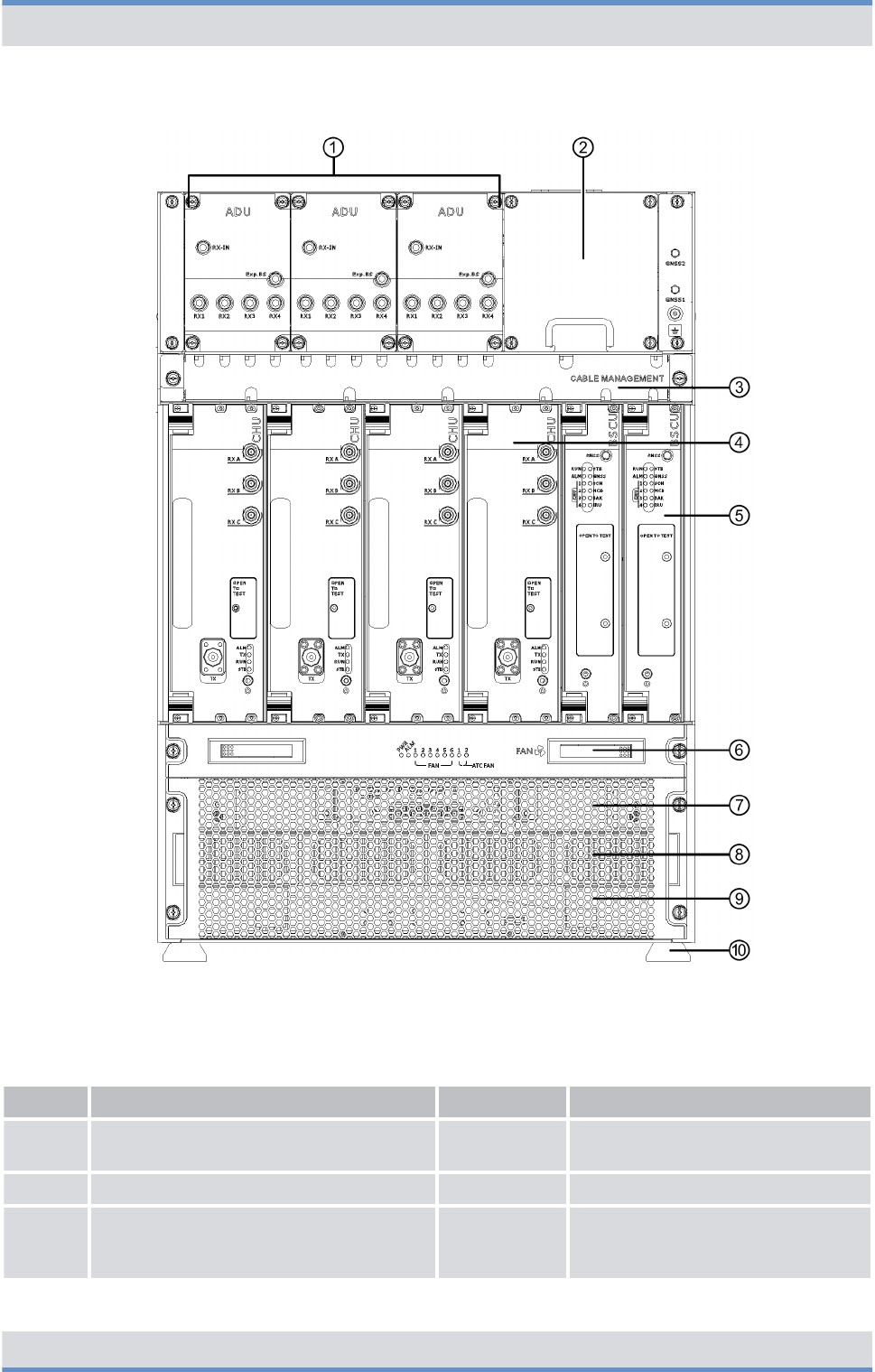
Figure 5: DIB-R5 flexibleTx (front view)
Legend: DIB-R5 flexibleTx (front view)
No. Component Number Described in
1 ADU 1 to 3
Ä
Chapter 3.2.4.1 “Active Divider
Unit (ADU)” on page 45
2 Cable routing for Tx cable 1 ---
3 Cable routing for Rx and GNSS cable
(Global Navigation Satellite System,
GNSS)
1 ---
Product description
DIB-R5 flexibleTx
25Operation Manual 90DIBR5flexibleTxOM02 - 1.2

No. Component Number Described in
4 TETRA Channel Unit (CHU) 1 to 4
Ä
Chapter 3.2.5 “TETRA Channel
Unit (CHU)” on page 46
5 Base Station Controller Unit (BSCU) 1 to 2
Ä
Chapter 3.2.6 “Base Station Con-
troller Unit (BSCU)” on page 49
6 Fan unit 1
Ä
Chapter 3.2.7 “Fan unit”
on page 53
7 Air entry for fan unit 1 ---
8nVAC power supply:
Power Supply Unit (PSU) including
Power Supply Module (PSM)
nVDC power supply:
Dummy plate
n1 to 2
n0
Ä
Chapter 3.2.2.2 “Power Supply
Unit (PSU) including Power Supply
Module (PSM)” on page 40
9 Dummy plate 1 ---
10 Support feet 4 ---
The following figure shows the top view of the DIB-R5 flexibleTx with VAC power supply.
The following table describes the components in greater detail.
Product description
DIB-R5 flexibleTx
26 Operation Manual 90DIBR5flexibleTxOM02 - 1.2
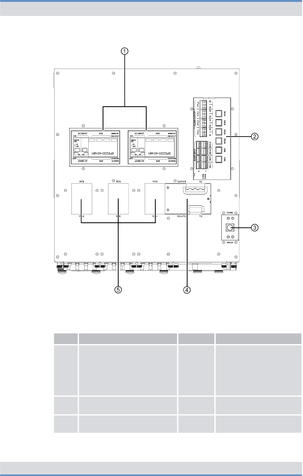
Figure 6: DIB-R5 flexibleTx (top view)
Legend: DIB-R5 flexibleTx (top view)
No. Component Number Described in
1nVAC power supply:
AC Power Distribution Module
(APDM)
nVDC power supply:
DC Power Distribution Module
(DPDM)
1 to 2 n
Ä
Chapter 3.2.2 “VAC
power supply”
on page 38
n
Ä
Chapter 3.2.3 “VDC
power supply”
on page 42
2 Connection panel 1
Ä
Chapter 3.2.1.2 “Connec-
tion panel” on page 36
3 GNSS splitter 1
Ä
Chapter 3.2.1.3 “GNSS
splitter” on page 38
Product description
DIB-R5 flexibleTx
27Operation Manual 90DIBR5flexibleTxOM02 - 1.2
No. Component Number Described in
4 Grommet 1 ---
5 Dummy plate 3 ---
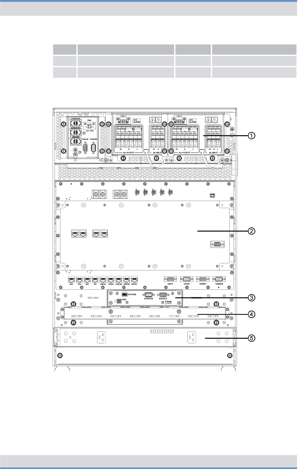
The following figure shows the rear view of the DIB-R5 flexibleTx with VAC power supply
and opened cover. The following table describes the components in greater detail.
Figure 7: DIB-R5 flexibleTx with opened cover (rear view)
Product description
DIB-R5 flexibleTx
28 Operation Manual 90DIBR5flexibleTxOM02 - 1.2

Legend: DIB-R5 flexibleTx with opened cover (rear view)
No. Component Number Described in
1nVAC power supply:
AC Power Distribution Module
(APDM)
nVDC power supply:
DC Power Distribution Module
(DPDM)
1 to 2 n
Ä
Chapter 3.2.2 “VAC
power supply”
on page 38
n
Ä
Chapter 3.2.3 “VDC
power supply”
on page 42
2 Backplane 1
Ä
Chapter 3.2.8 “Backplane”
on page 55
3 Fan unit 1
Ä
Chapter 3.2.7 “Fan unit”
on page 53
4 Cable routing 1 ---
5nVAC power supply:
Power Supply Unit (PSU)
including Power Supply
Module (PSM)
nVDC power supply:
Not available
n1 to 4
n---
Ä
Chapter 3.2.2.2 “Power
Supply Unit (PSU) including
Power Supply Module
(PSM)” on page 40
---
3.1 Characteristics of the DIB-R5
The DIB-R5 offers a high degree of flexibility and allows demand-oriented characteristics,
e.g. with respect to power supply, frequencies and redundancy options. Depending on
the characteristic, different components can be installed.
The following table provides an overview of the properties.
Properties of the DIB-R5
Property DIB-R5 advanced DIB-R5 compact DIB-R5 flexibleTx
Max. number of CHUs n4 per equipment
rack
n2 equipment racks
possible
n2 per compact
rack
n2 compact racks
possible
n4 per compact
rack
n1 compact rack
possible
Max. number of carriers/channels n8 carriers
n32 channels
n4 carrier
n16 channels
n4 carrier
n16 channels
Redundancy for CHUs ✓ ✓ ✓
Redundancy for control unit
(BSCU)
✓ ✓ ✓
Power supply VAC or VDC
Product description
Characteristics of the DIB-R5
DIB-R5 flexibleTx
29Operation Manual 90DIBR5flexibleTxOM02 - 1.2

Property DIB-R5 advanced DIB-R5 compact DIB-R5 flexibleTx
Redundancy with VAC power supply by means of following, optional
additions:
nRedundant rectifier modules (Power Supply Module, PSM)
nRedundant power supply lines
Triple diversity reception ✓ ✓ ✓
Antenna coupling system Cavity combiner
(motor tuned)
Hybrid combiner External antenna cou-
pling system at the
site
One of the following transmitting filters:
nDUPLEXER
for a common transmitting/receiving
antenna (Tx/Rx antenna). Can be com-
bined with up to two receiving antennas
(Rx antennas).
nTX FILTER
for separate transmitting and receiving
antennas (Tx and Rx antennas). Must be
combined with up to three receiving
antennas (Rx antennas).
3.2 Components
The following table lists the components of the DIB-R5 flexibleTx for each compact rack.
Components of the DIB-R5 flexibleTx
Component Described in
Ä
Connection and control
panel
Ä
On/off switch
Ä
Chapter 3.2.1.1 “On/off
switch” on page 36
Ä
Connection panel
Ä
Chapter 3.2.1.2 “Connec-
tion panel” on page 36
Ä
GNSS splitter
Ä
Chapter 3.2.1.3 “GNSS
splitter” on page 38
Ä
VAC power supply
Ä
Chapter 3.2.2 “VAC power
supply” on page 38
Ä
VDC power supply
Ä
Chapter 3.2.3 “VDC power
supply” on page 42
Ä
Divider Unit (DIU)
Ä
Active Divider Unit (ADU)
Ä
Chapter 3.2.4.1 “Active
Divider Unit (ADU)”
on page 45
Product description
Components
DIB-R5 flexibleTx
30 Operation Manual 90DIBR5flexibleTxOM02 - 1.2

Component Described in
Ä
TETRA Channel Unit (CHU)
Ä
Chapter 3.2.5 “TETRA
Channel Unit (CHU)”
on page 46
Ä
Base Station Controller Unit (BSCU)
Ä
Chapter 3.2.6 “Base Sta-
tion Controller Unit (BSCU)”
on page 49
Ä
Fan unit
Ä
Chapter 3.2.7 “Fan unit”
on page 53
Ä
Backplane
Ä
Chapter 3.2.8 “Backplane”
on page 55
3.2.1 Connection and control panel
DIB-R5 flexibleTx features a connection and control panel at the top to which the antenna
and power supply cables can conveniently be connected. In addition, the connection and
control panel provides access to all the elements that are required for additional connec-
tions and operation.
The following figures show the connection and control panel for VAC and VDC power
supply in the top view. The following table describes it in detail.
Product description
Components > Connection and control panel
DIB-R5 flexibleTx
31Operation Manual 90DIBR5flexibleTxOM02 - 1.2
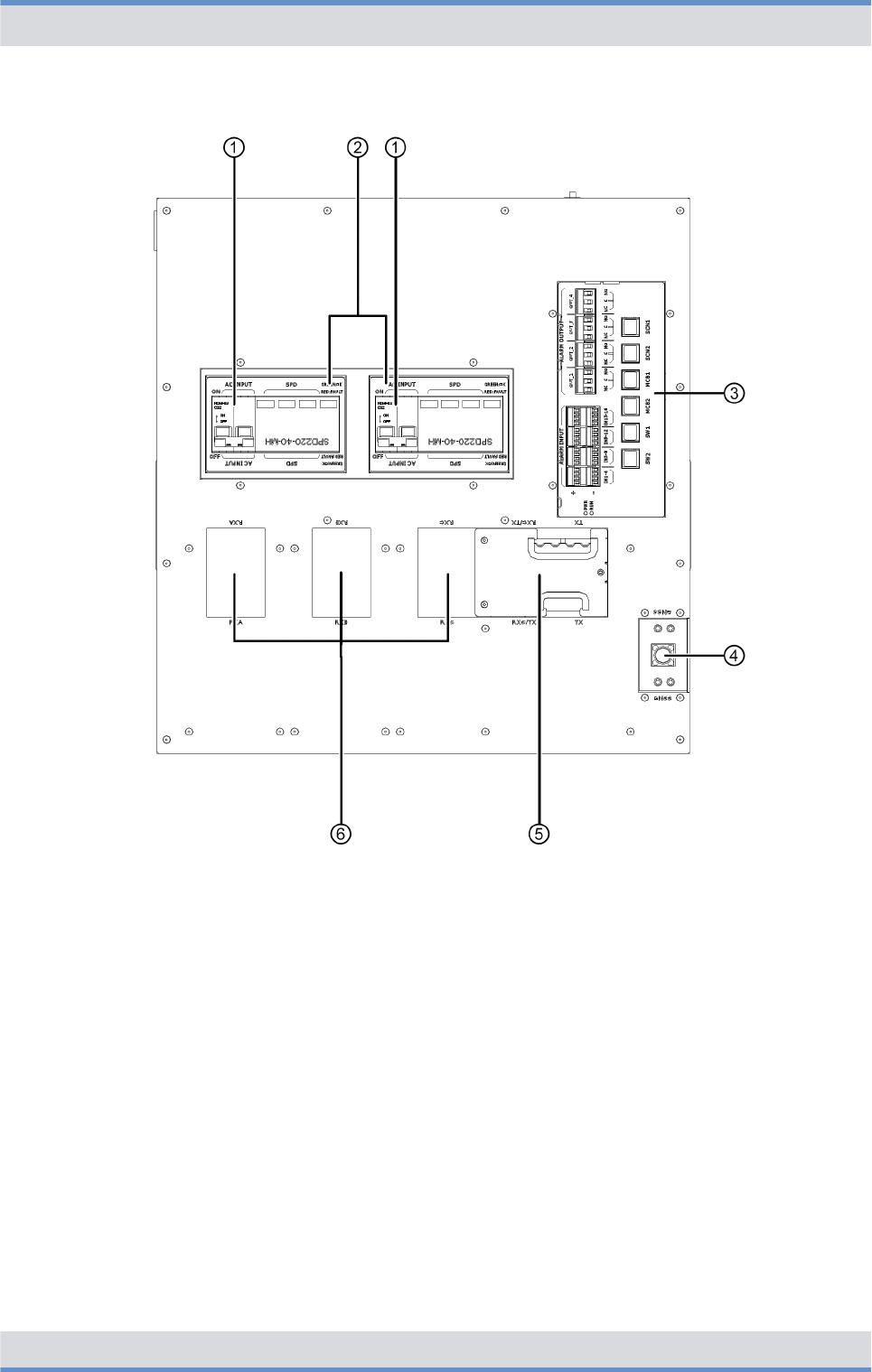
Figure 8: Connection and control panel for VAC power supply (top view)
Product description
Components > Connection and control panel
DIB-R5 flexibleTx
32 Operation Manual 90DIBR5flexibleTxOM02 - 1.2
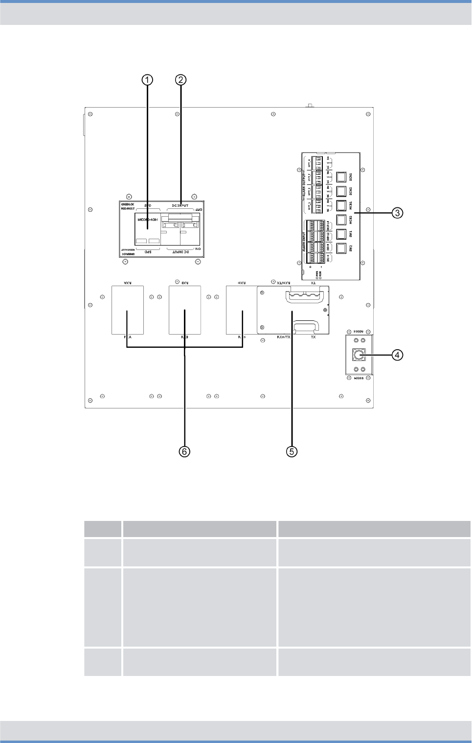
Figure 9: Connection and control panel for VDC power supply (top view)
Legend: Connection and control panel (top view)
No. Component Description
1 On/off switch refer to
Ä
Chapter 3.2.1.1 “On/off switch”
on page 36
2nVAC power supply:
AC Power Distribution Module
(APDM)
nVDC power supply:
DC Power Distribution Module
(DPDM)
nrefer to
Ä
Chapter 3.2.2 “VAC power
supply” on page 38
nrefer to
Ä
Chapter 3.2.3 “VDC power
supply” on page 42
3 Connection panel refer to
Ä
Chapter 3.2.1.2 “Connection
panel” on page 36
Product description
Components > Connection and control panel
DIB-R5 flexibleTx
33Operation Manual 90DIBR5flexibleTxOM02 - 1.2

No. Component Description
4 GNSS splitter refer to
Ä
Chapter 3.2.1.3 “GNSS splitter”
on page 38
5 Grommet ---
6 Dummy plate ---
3.2.1.1 On/off switch
The on/off switch is accessible via the Power Distribution Module (PDM) in the connection
and control panel. The PDM is the main component of the power supply and is used for
connecting the power supply and the power distribution to the hardware components of
the DIB-R5 flexibleTx.
nWith the VAC power supply, the on/off switch is available via the AC Power Distribu-
tion Module (APDM), refer to
Ä
Chapter 3.2.2 “VAC power supply” on page 38.
nWith the VDC power supply, the on/off switch is available via the DC Power Distribu-
tion Module (DPDM), refer to
Ä
Chapter 3.2.3 “VDC power supply” on page 42.
3.2.1.2 Connection panel
The connection panel combines all the essential connections, centrally and easily acces-
sible at the top side, e.g. for connection to the transport network. Isolated alarm contacts
provide digital alarm inputs and alarm outputs. The alarm inputs can be monitored via the
network management system (NMS). This allows, for example, to monitor the status of
the Surge Protection Device (SPD) of the DIB-R5 flexibleTx in the NMC-511 FaultMan-
ager. Alarms with the corresponding critical state can be signaled externally via the alarm
outputs, e.g. with a connected light or ringing.
The connection panel is implemented by the alarm/connection box.
The following figure shows the top view of the connection panel. The following table
describes it in detail.
Product description
Components > Connection and control panel
DIB-R5 flexibleTx
34 Operation Manual 90DIBR5flexibleTxOM02 - 1.2
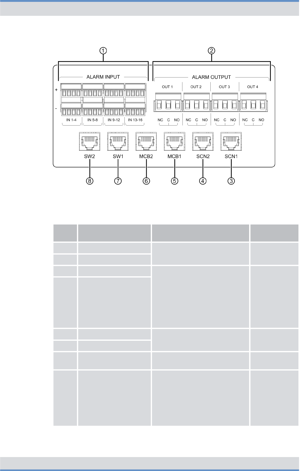
Figure 10: Connection panel (top view)
Legend: Connection panel (top view)
No. Component Description Connection
type
1 ALARM INPUT Alarm inputs/outputs for wiring
alarm contacts
Connector with
screw terminal
2 ALARM OUTPUT
3 SCN1 Connection to an IP transport net-
work or for connecting a switching
controller node (SCN).
With controller redundancy
(optional), both connections must
be connected to design the
ethernet connections of the
BSCUs redundantly.
RJ45
4 SCN2
5 MCB1 Connection for applications RJ45
6 MCB2
7 SW1 Connection of the service com-
puter (local)
RJ45
8 SW2 Connection of service computer
(local) ‒ optional for controller
redundancy
This connection is used only if
software downloads should be
performed purposefully only for
the redundant BSCU.
RJ45
Product description
Components > Connection and control panel
DIB-R5 flexibleTx
35Operation Manual 90DIBR5flexibleTxOM02 - 1.2

3.2.1.3 GNSS splitter
The GNSS splitter (Global Navigation Satellite System) is used for connecting the GNSS
antenna and the allocation and distribution of the received GNSS signal (e.g. GPS, Gal-
ileo or Glonass) to up to two BSCUs. The GNSS splitter is installed in the connection and
control panel.
3.2.2 VAC power supply
DIB-R5 flexibleTx can be operated with an input voltage of 90 VAC to 250 VAC.
The VAC power supply consists of the following components:
n
Ä
AC Power Distribution Module (APDM)
n
Ä
Power Supply Unit (PSU) including Power Supply Module (PSM)
3.2.2.1 AC Power Distribution Module (APDM)
The AC Power Distribution Module (APDM) is used for connecting the power supply and
the power distribution to the backplane and the installed hardware components. The
APDM is used for the VAC power supply. The VAC input voltage is fed via the Power
Supply Unit (PSU), converted to the required operating voltage, and subsequently distrib-
uted to the backplane and the installed hardware components.
With redundant power supply line, two APDMs are installed (optional). The redundancy
options of the power supply are described in
Ä
Chapter 3.5.6 “Redundant VAC power
supply” on page 62.
The following figure shows the top view of the APDM. The following table describes it in
detail.
Product description
Components > VAC power supply
DIB-R5 flexibleTx
36 Operation Manual 90DIBR5flexibleTxOM02 - 1.2
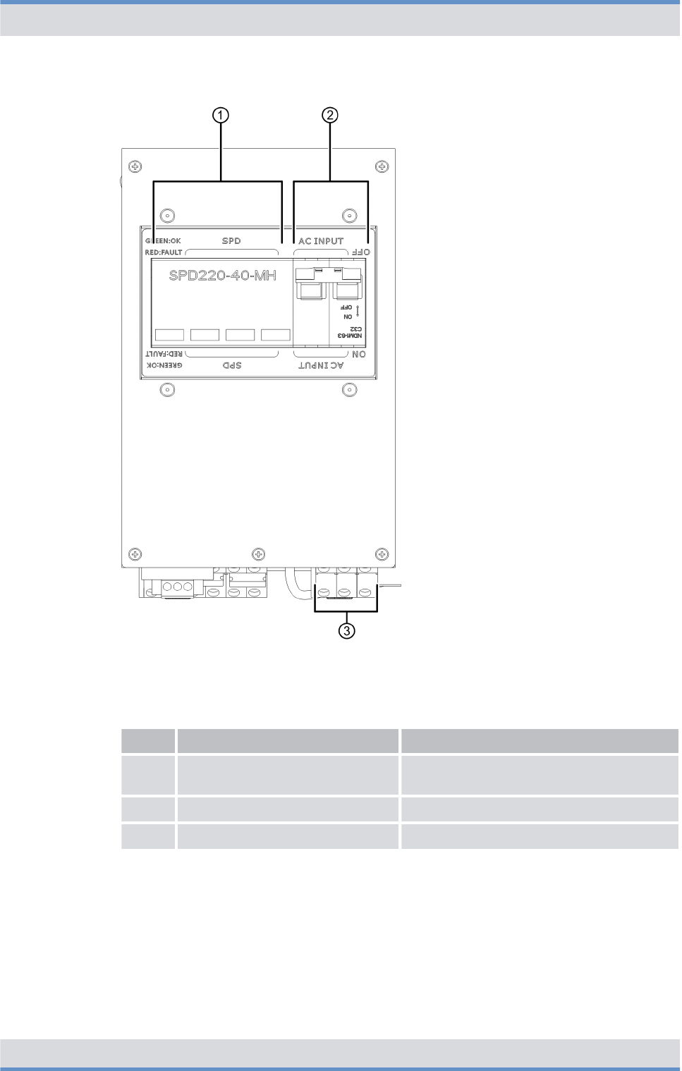
Figure 11: APDM (top view)
Legend: APDM (top view)
No. Component Description
1 Surge protection Surge Protection Device (SPD) of the
DIB-R5 flexibleTx
2 On/off switch On/off switch of the DIB-R5 flexibleTx
3 Terminals Terminals for VAC input voltage
The following figure shows the front view of the APDM. The following table describes it in
detail.
Product description
Components > VAC power supply
DIB-R5 flexibleTx
37Operation Manual 90DIBR5flexibleTxOM02 - 1.2

Figure 12: APDM (front view)
Legend: APDM (front view)
No. Component Description
1 SPD ALARM Connection for monitoring the surge protection device (SPD)
2 L Input Phase conductor connection for VAC input
voltage
3 N Neutral conductor connection for VAC input
voltage
4 PE Protective conductor connection for VAC input
voltage
5 L Output Phase conductor connection for the VAC output
voltage ‒ already connected with the PSU at
time of delivery
6 N Neutral conductor connection for the VAC output
voltage ‒ already connected with the PSU at
time of delivery
7 PE Protective conductor connection for the VAC
output voltage ‒ already connected with the
PSU at time of delivery
3.2.2.2 Power Supply Unit (PSU) including Power Supply Module (PSM)
The Power Supply Unit (PSU) is a component of the power supply and is used for the VAC
power supply.
Depending on the power supply, the number of installed CHUs and, if applicable, a
redundantly implemented power supply, up to four Power Supply Modules (PSM) are
installed.
Product description
Components > VAC power supply
DIB-R5 flexibleTx
38 Operation Manual 90DIBR5flexibleTxOM02 - 1.2
Depending on the power supply, the number of installed CHUs and, if applicable, a
redundantly implemented power supply, up to two Power Supply Modules (PSM) are
installed.
The Power Supply Module (PSM) is a rectifier module and is used with VAC power supply.
The PSM is used for converting AC voltage (VAC) into DC voltage (VDC).
The following table describes the recommended number of PSMs depending on the
power supply and the number of installed CHUs per equipment or compact rack. The
number is higher if redundant PSMs are used (maximum 4 per equipment or compact
rack).
Recommended number of PSMs (per equipment or compact rack)
Power supply Number of CHUs Number of PSMs
90 VAC - 185 VAC (nominal) 1 to 2 2
3 to 4 4
185 VAC - 250 VAC (nominal) 1 to 2 1
3 to 4 2
The following figure shows the front view of the PSU. The following table describes it in
detail.
Figure 13: PSU (front view)
Legend: PSU (front view)
No. Component Description
1 Mounting frame The mounting frame is used for accommodating the Power
Supply Modules (PSM)
2 Power Supply
Module (PSM)
Number depending on the VAC voltage at the site and the
number of installed CHUs, refer to
Ä
Table “Recommended
number of PSMs (per equipment or compact rack)” on
page 39
The following figure shows the front view of a PSM. The following table describes it in
detail.
Product description
Components > VAC power supply
DIB-R5 flexibleTx
39Operation Manual 90DIBR5flexibleTxOM02 - 1.2
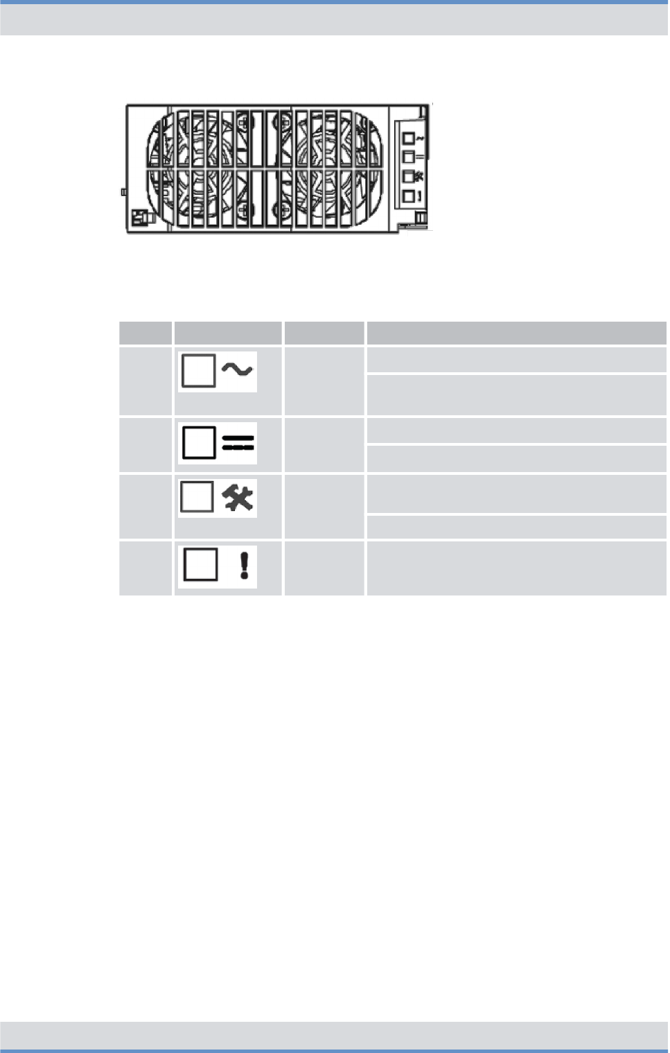
Figure 14: PSM (front view)
Legend: PSM (front view)
No. Component Color Description
1 green Lights if the VAC input voltage is OK
Flashes if the VAC input voltage is outside the
permissible voltage range
2 green Lights if the VDC output voltage is OK
Flashes if the VDC output voltage is overloaded
3 yellow Lights if the temperature warning threshold is
exceeded
Flashes in case of service
4 red Lights in case of an error
3.2.3 VDC power supply
The DIB-R5 flexibleTx can be operated with an input voltage of 48 VDC.
The DC Power Distribution Module (DPDM) is used for connecting the power supply and
the power distribution to the backplane and the installed hardware components. The
DPDM is used for the VDC power supply. The VDC input voltage is distributed directly to
the backplane and the installed hardware components.
The following figure shows the top view of the DPDM. The following table describes it in
detail.
Product description
Components > VDC power supply
DIB-R5 flexibleTx
40 Operation Manual 90DIBR5flexibleTxOM02 - 1.2
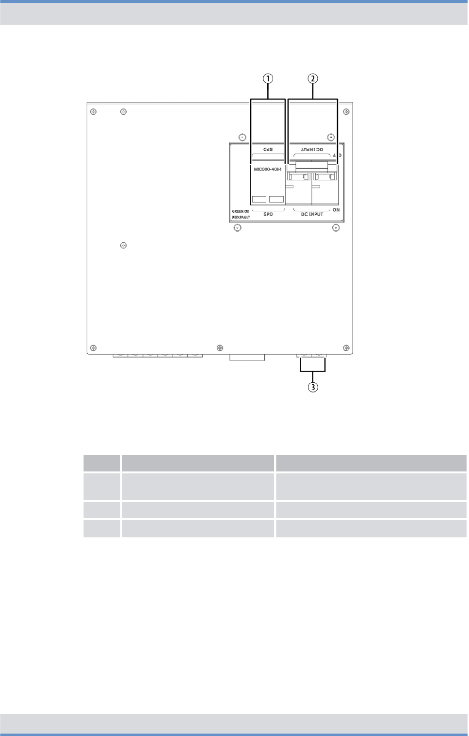
Figure 15: DPDM (top view)
Legend: DPDM (top view)
No. Component Description
1 Surge protection Surge Protection Device (SPD) of the
DIB-R5 flexibleTx
2 On/off switch On/off switch of the DIB-R5 flexibleTx
3 Terminals Terminals for VDC input voltage
The following figure shows the front view of the DPDM. The following table describes it in
detail.
Product description
Components > VDC power supply
DIB-R5 flexibleTx
41Operation Manual 90DIBR5flexibleTxOM02 - 1.2

Figure 16: DPDM (front view)
Legend: DPDM (front view)
No. Component Description
1 SPD ALARM Connection for monitoring the Surge Pro-
tection Device (SPD)
2 DC INPUT -48 V Connection for the negative voltage line
(input voltage)
3 RTN Connection for the positive voltage line
(input voltage)
4 DC OUTPUT -48 V Connection for the negative voltage line
(output voltage) ‒ already connected with
the backplane at the time of delivery
5 RTN Connection for the positive voltage line
(output voltage) ‒ already connected with
the backplane at the time of delivery
3.2.4 Divider Unit (DIU)
The Divider Unit (DIU) is a component of the antenna coupling system and used for dis-
tributing a reception signal received by the antennas to the installed CHUs.
Different DIUs are used in the DIB-R5 flexibleTx:
n
Ä
Active Divider Unit (ADU)
The type used and the number of DIUs depends on the number of antennas and carriers.
Product description
Components > Divider Unit (DIU)
DIB-R5 flexibleTx
42 Operation Manual 90DIBR5flexibleTxOM02 - 1.2
3.2.4.1 Active Divider Unit (ADU)
The Active Divider Unit (ADU) is used for amplifying the received Rx signals. The Rx sig-
nals are distributed by the ADU and forwarded to the respective Channel Units (CHU).
The number of ADUs depends on the number of receiving antennas (Rx antennas). One
ADU is required for every Rx antenna.
This component features an antenna connection at the front side with which an external
antenna coupling system can be connected, refer to
Ä
Chapter 3.2.1 “Connection and
control panel” on page 31.
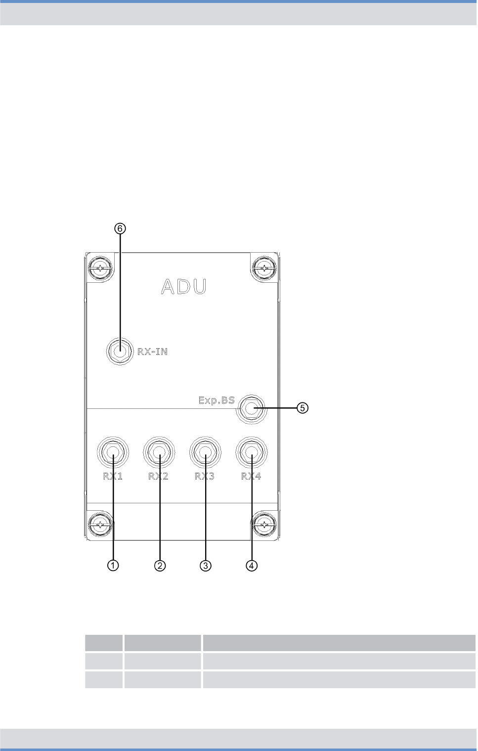
The following figure shows the front view of the ADU. The following table describes it in
detail.
Figure 17: ADU (front view)
Legend: ADU (front view)
No. Component Description
1 RX1 Connector for the connection with CHU 1
2 RX2 Connector for the connection with CHU 2
Product description
Components > Divider Unit (DIU)
DIB-R5 flexibleTx
43Operation Manual 90DIBR5flexibleTxOM02 - 1.2

No. Component Description
3 RX3 Connector for the connection with CHU 3
4 RX4 Connector for the connection with CHU 4
5 Exp. BS Not used for the time being
6 RX-IN Connector for the connection with an external antenna cou-
pling system
3.2.5 TETRA Channel Unit (CHU)
The TETRA Channel Unit (CHU) is the transceiver module of the DIB-R5 and provides
four radio channels for the voice and data transmission in transmitting and receiving
direction (downlink and uplink) via one carrier signal. A transceiver consists of transmitter,
receiver and transceiver software for the TETRA protocol and generates a modulated RF
signal (carrier) with which signaling data and payload between the base station and the
terminals are exchanged. In addition to providing the carrier signal, the CHU provides
monitoring and control functions, with which the fan speed can be controlled dynamically,
for example.
The following figure shows the front view of the CHU. The following table describes it in
detail.
Product description
Components > TETRA Channel Unit (CHU)
DIB-R5 flexibleTx
44 Operation Manual 90DIBR5flexibleTxOM02 - 1.2

Figure 18: CHU (front view)
Legend: CHU (front view)
No. Component Description
1 RX A Rx receiver input A
2 RX B Rx receiver input B
3 RX C Rx receiver input C
4 OPEN TO TEST Connectors for test and service purposes, refer to
Ä
Table “Legend: Connectors for test and service
purposes (OPEN TO TEST) of the CHU” on
page 48
5 Indicators (LEDs) Status display of the CHU, refer to
Ä
Table “Legend: Indicators (LEDs) of the CHU” on
page 48
Product description
Components > TETRA Channel Unit (CHU)
DIB-R5 flexibleTx
45Operation Manual 90DIBR5flexibleTxOM02 - 1.2
No. Component Description
6 Power button Power button for shutting down and restarting the
hardware component
For shutdown and restart, the power button must be
pressed for at least 5 seconds.
7 TX Tx transmitter output
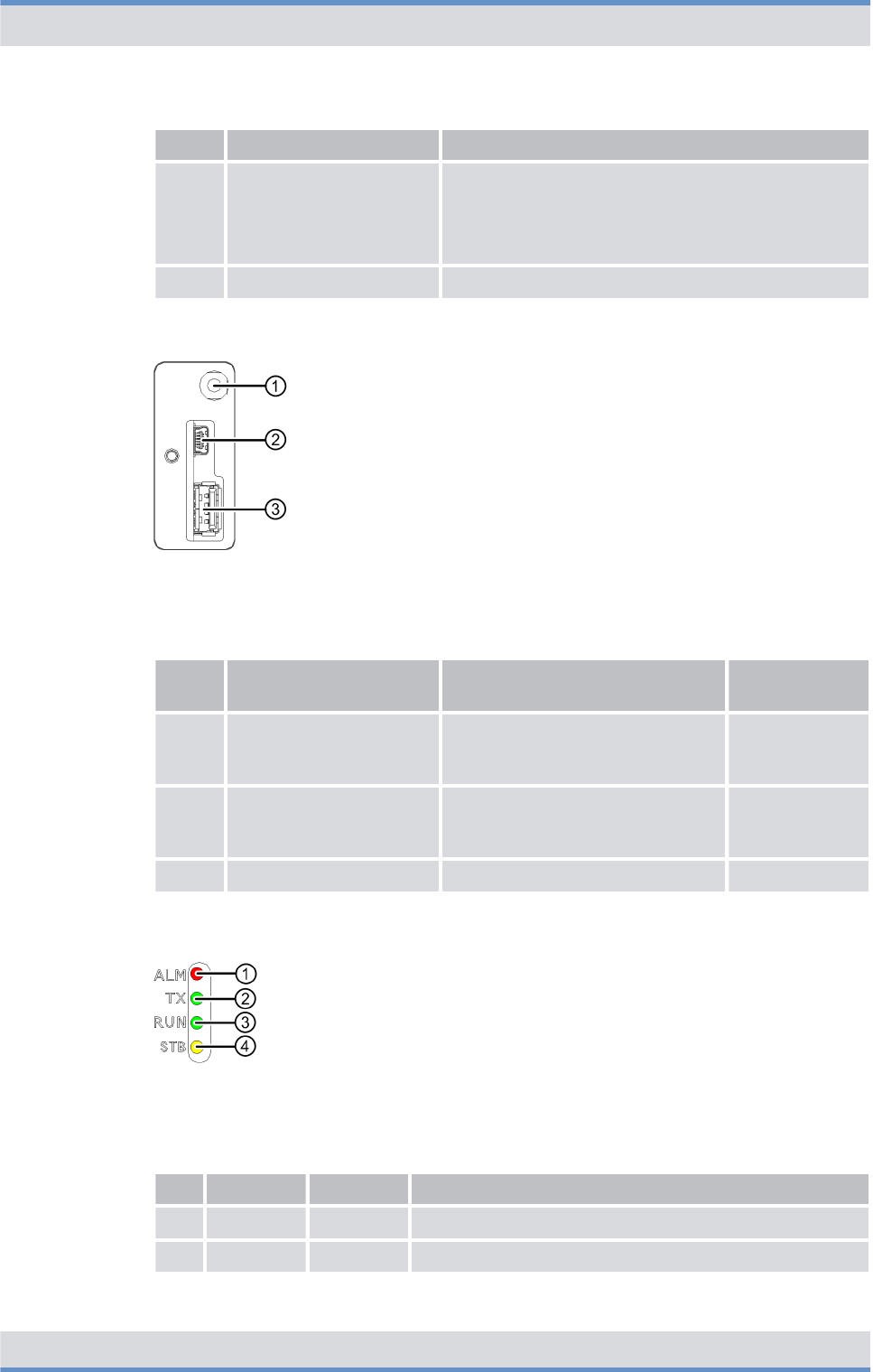
The following figure shows the connectors for test and service purposes (OPEN TO
TEST) of the CHU. The following table describes it in detail.
Figure 19: Connectors for test and service purposes (OPEN TO TEST) of the CHU
Legend: Connectors for test and service purposes (OPEN TO TEST) of the CHU
No. Component Description Connection
type
1 Multi-frame Connector for test and approval
measurements of the receiving
quality
SMB (male)
2 Mini-USB USB port for the serial connection
to the console of the operating
system
Mini-USB
3 USB-A USB port, e.g. for data exchange USB A
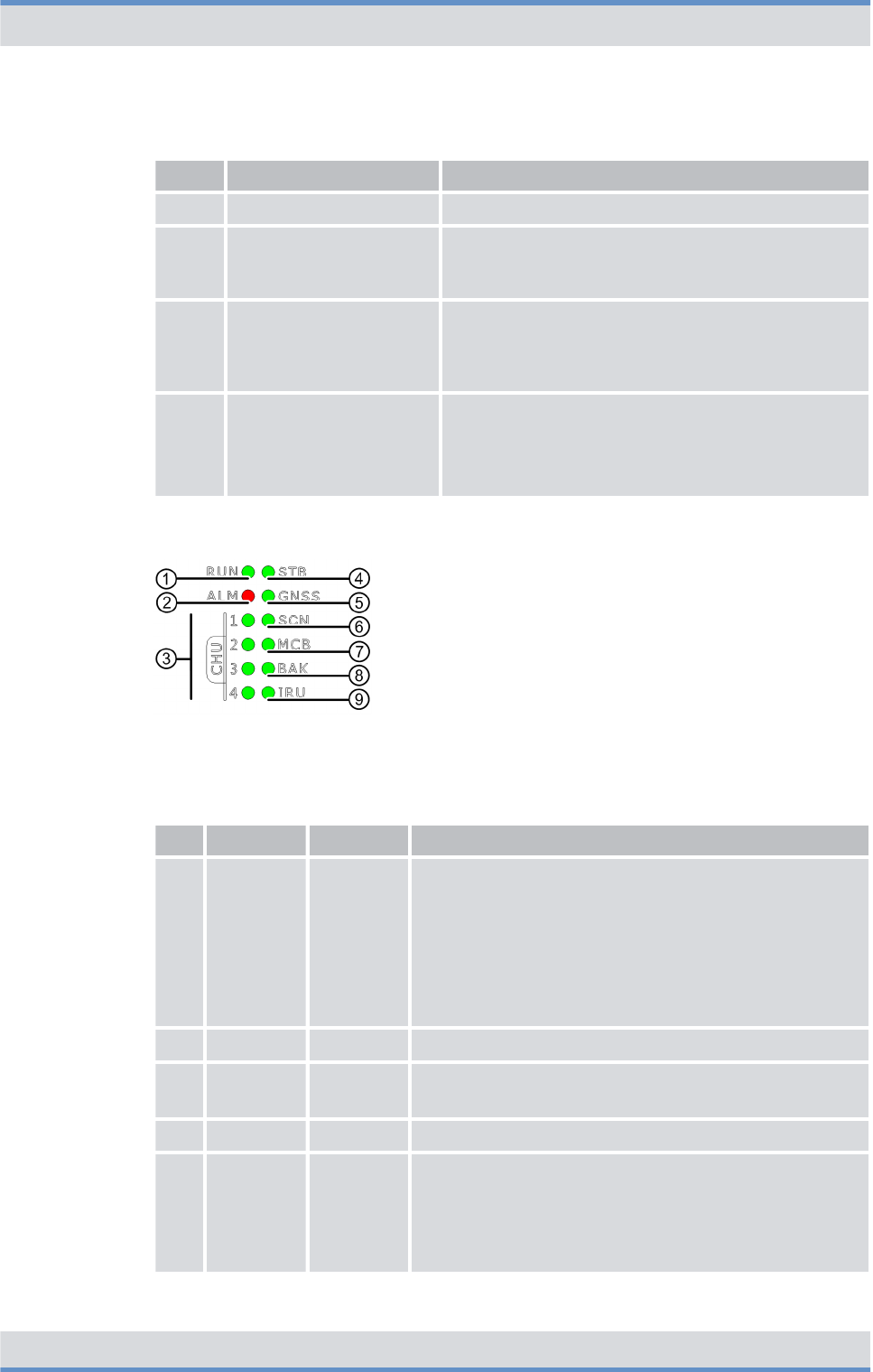
The following figure shows the indicators (LEDs) of the CHU. The following table
describes it in detail.
Figure 20: Indicators (LEDs) of the CHU
Legend: Indicators (LEDs) of the CHU
No. LED Color Description
1 ALM red Lights in case of an error
2 TX green Lights green if the transmitter of the CHU is switched on
Product description
Components > TETRA Channel Unit (CHU)
DIB-R5 flexibleTx
46 Operation Manual 90DIBR5flexibleTxOM02 - 1.2

No. LED Color Description
3 RUN green Lights if the CHU is in operation
4 STB yellow Lights if the CHU is in standby operation
3.2.6 Base Station Controller Unit (BSCU)
The Base Station Controller Unit (BSCU) is the control unit of the base station and
secures the connections inside of the DIB-R5 flexibleTx as well as to external network
constituents such as system controller nodes.
In addition, the BSCU receives and distributes the clock and time signals for the synchro-
nization of the base stations that are acquired via the integrated GNSS component
(Global Navigation Satellite System) with a connected antenna. GNSS includes all the
common systems, such as GPS, Galileo and Glonass. As an option, time is obtained via
the Precision Time Protocol (PTP) from a so-called reference time source (grandmaster
clock).
In addition, the BSCU is the interface to ACCESSNET-T IP and, as such, secures the
connection to other network constituents, such as system controller nodes, the network
management system (NMS) or applications.
The BSCU is a modular subrack for the DIB-R5 flexibleTx and is installed in the basic
rack. To increase availability, up to two BSCUs can be installed. If the first BSCU fails, the
redundant BSCU automatically assumes operation in order to quickly resume the radio
coverage. The failed BSCU can now be replaced during running operation.
The following figure shows the front view of the BSCU. The following table describes it in
detail.
Product description
Components > Base Station Controller Unit (BSCU)
DIB-R5 flexibleTx
47Operation Manual 90DIBR5flexibleTxOM02 - 1.2
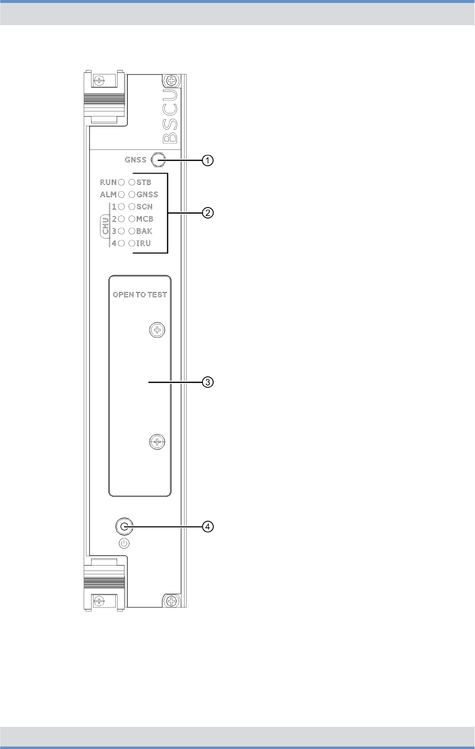
Figure 21: BSCU (front view)
Product description
Components > Base Station Controller Unit (BSCU)
DIB-R5 flexibleTx
48 Operation Manual 90DIBR5flexibleTxOM02 - 1.2
Legend: BSCU (front view)
No. Component Description
1 GNSS GNSS antenna connector (SMA)
2 Indicators (LEDs) Status display of the BSCU, refer to
Ä
Table “Legend: Indicators (LEDs) of the
BSCU” on page 51
3 OPEN TO TEST Connectors for test and service purposes, refer to
Ä
Table “Legend: Connectors for test and service
purposes (OPEN TO TEST) of the BSCU” on
page 52
4 Power button Power button for shutting down and restarting the
hardware component
For shutdown and restart, the power button must be
pressed for at least 5 seconds.
The following figure shows the indicators (LEDs) of the BSCU. The following table
describes it in detail.
Figure 22: Indicators (LEDs) of the BSCU
Legend: Indicators (LEDs) of the BSCU
No. LED Color Description
1 RUN green nFlashes slowly (1 s) if the BSCU is in operation
nFlashes quickly (250 ms) if the BSCU
–starts up
–has been shut down
nLights if the power button is pressed briefly
nOff (6 s) if the power button is pressed and held for
more than 5 seconds
2 ALM red Lights in case of an error
3 CHU 1 to
4
green nLights if connections to CHUs exist
nFlashes if data are being transferred
4 STB green Lights if the BSCU is in standby operation
5 GNSS green nLights if the internal clock system of the base sta-
tion is synchronous according to its configuration
nFlashes if the internal clock system attempts to
reach a synchronization
nOff if the internal clock system is faulty
Product description
Components > Base Station Controller Unit (BSCU)
DIB-R5 flexibleTx
49Operation Manual 90DIBR5flexibleTxOM02 - 1.2
No. LED Color Description
6 SCN green nLights if an ethernet connection exists for con-
necting a system controller node
nFlashes if data are being transferred
7 MCB green nLights if a connection exists between the integrated
components ethernet switch and BSCU mainboard
(MCB)
nFlashes if data are being transferred
8 BAK green nLights if a connection exists between redundant
BSCUs
nFlashes if data are being transferred
9 IRU green nLights if a connection to an Interconnection Relay
Unit (IRU) exists ‒ with expansion rack only
nFlashes if data are being transferred
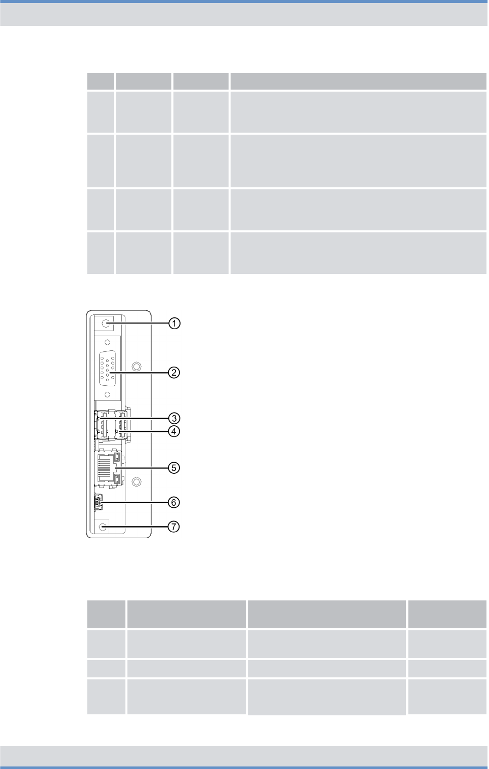
The following figure shows the connectors for test and service purposes (OPEN TO
TEST) of the BSCU. The following table describes it in detail.
Figure 23: Connectors for test and service purposes (OPEN TO TEST) of the BSCU
Legend: Connectors for test and service purposes (OPEN TO TEST) of the BSCU
No. Component Description Connection
type
1 10 MHz out Connector for measuring instru-
ments
SMB (male)
2 VGA Monitor port VGA
3 USB1 USB port, e.g. for connecting a
keyboard or a USB stick for soft-
ware updates
USB A
Product description
Components > Base Station Controller Unit (BSCU)
DIB-R5 flexibleTx
50 Operation Manual 90DIBR5flexibleTxOM02 - 1.2
No. Component Description Connection
type
4 USB2 USB A
5 LAN Ethernet port for the service com-
puter
RJ45
6 Mini-USB USB port for service purposes Mini-USB
7 Reset button Reset button for restarting the
Main Processing Unit (MPU) inte-
grated component on the BSCU
main board
---
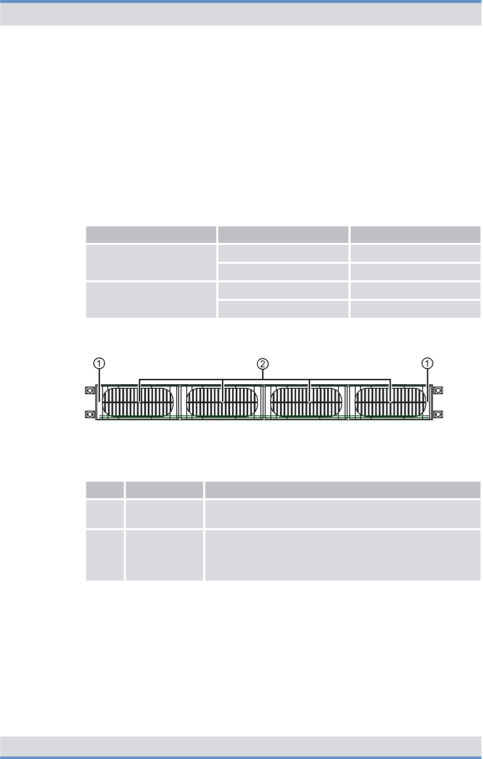
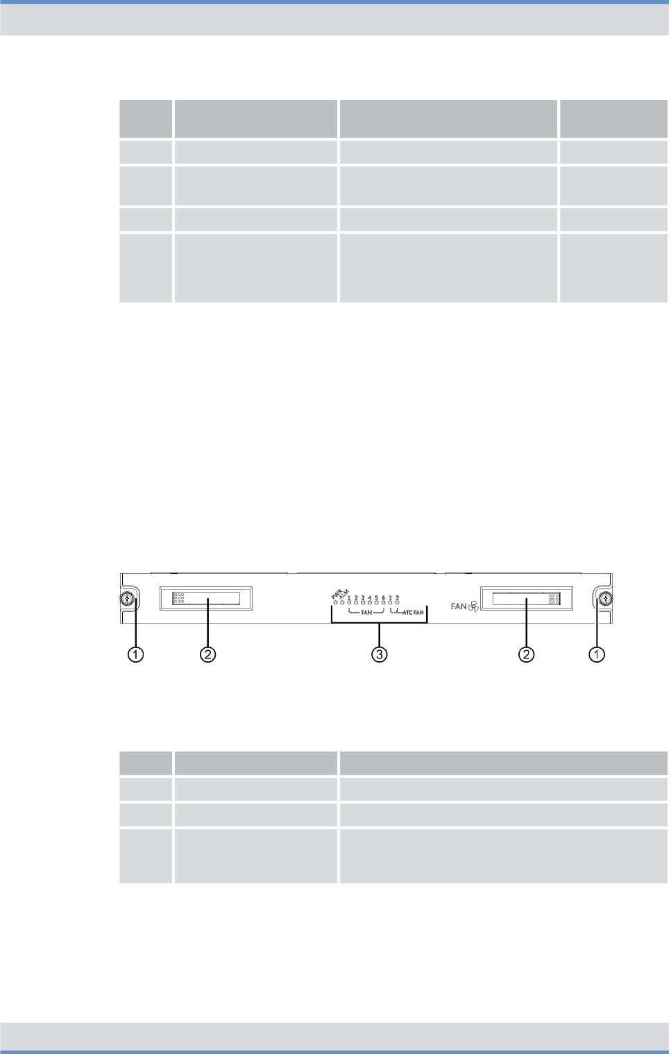
3.2.7 Fan unit
The fan unit is used for cooling the installed components within the DIB-R5 flexibleTx.
The air filter pad is affixed to the inside of the front door and filters the dirt and dust parti-
cles from the air.
The fan unit is implemented in the form of a fan subrack for the DIB-R5 flexibleTx and
contains six fans. For every fan, the state is signaled via an LED so that the status is
visible from the outside. The ambient temperature is continuously being monitored and
the fan speed is adjusted accordingly. In addition, the fans of the cavity combiner are
being monitored.
The following figure shows the front view of the fan unit. The following table describes it in
detail.
Figure 24: Fan unit (front view)
Legend: Fan unit (front view)
No. Component Description
1 Mounting screw Screw for fastening in the compact rack
2 Handle Recessed handle for pulling out the fan unit
3 Indicators (LEDs) Status display of the fan unit, refer to
Ä
Table “Legend: Indicators (LEDs) of the fan
unit” on page 54
The following figure shows the indicators (LEDs) of the fan unit. The following table
describes it in detail.
Product description
Components > Fan unit
DIB-R5 flexibleTx
51Operation Manual 90DIBR5flexibleTxOM02 - 1.2
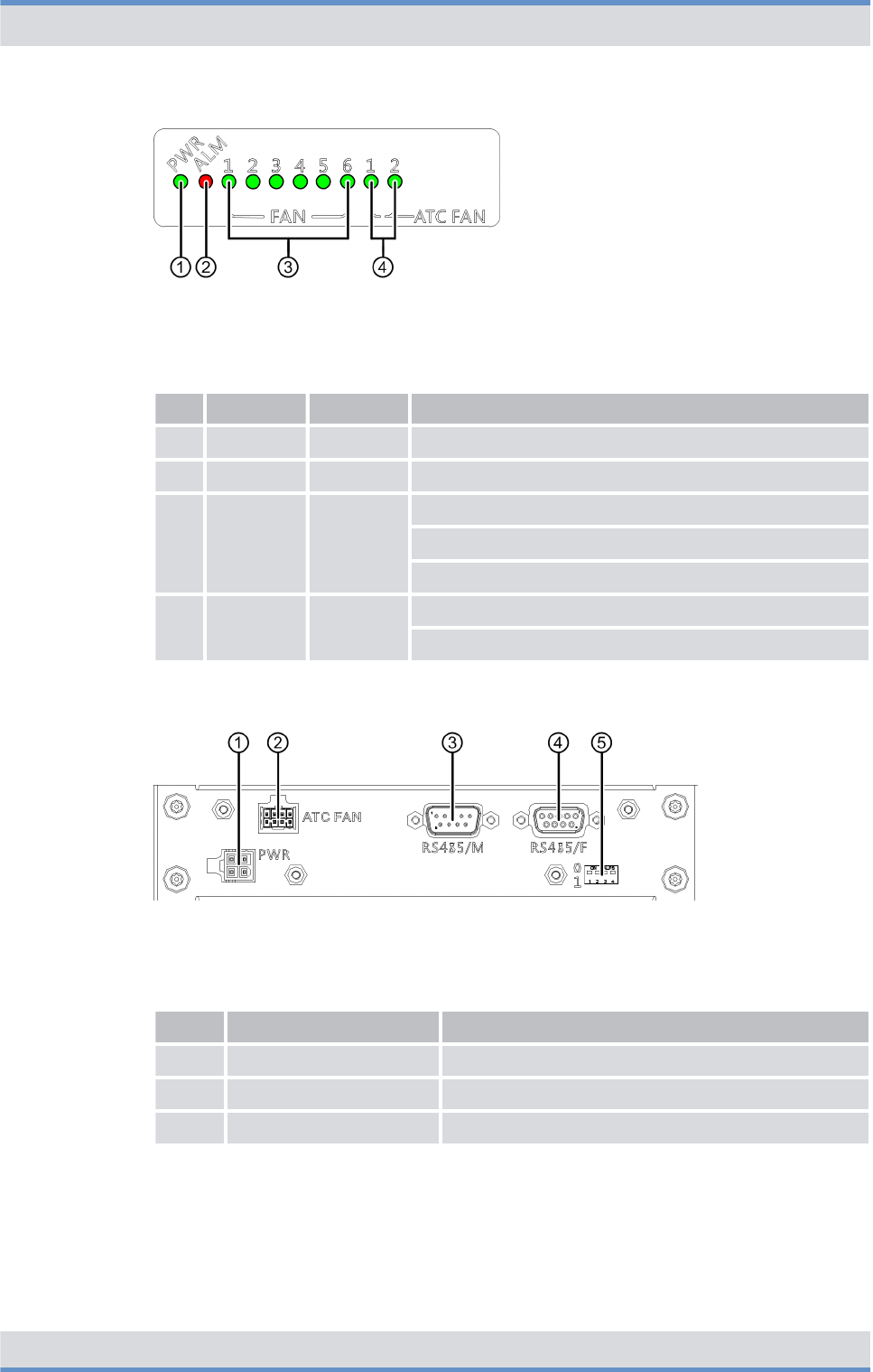
Figure 25: Indicators (LEDs) of the fan unit
Legend: Indicators (LEDs) of the fan unit
No. LED Color Description
1 PWR green Lights if the power supply of the fan unit is OK
2 ALM red Lights in case of an error
3 FAN 1 to 6 green Lights if the fan is OK
Flashes if the fan speed is not OK
Off if the fan is not OK
4 ATC FAN
1 to 2
green Lights if the fans of the cavity combiner are OK
Flashes if the fan speed is not OK
The following figure shows the rear view of the fan unit. The following table describes it in
detail.
Figure 26: Fan unit (rear view)
Legend: Fan unit (rear view)
No. Component Description
1 PWR Power supply
2 ATC FAN Connection for the fans of the cavity combiner
3 RS485/M Interface to the cavity combiner
Product description
Components > Fan unit
DIB-R5 flexibleTx
52 Operation Manual 90DIBR5flexibleTxOM02 - 1.2

No. Component Description
4 RS485/F Interface to the backplane
5 DIP switches Switches for monitoring the fans of the cavity
combiner
Switch positions:
nDIP switch (1)
–DIB-R5 advanced: top
–DIB-R5 compact: bottom
–DIB-R5 flexibleTx: bottom
nDIP switch (2 to 4): top
3.2.8 Backplane
Within the DIB-R5 flexibleTx, the backplane serves as central communication and supply
element. The backplane distributes the synchronization signals (clock and time) between
the BSCUs and CHUs, provides the ethernet connections and supplies all components
with operating voltage.
Then following figure shows the backplane from the rear view of the DIB-R5 flexibleTx.
The following table describes it in detail.
Figure 27: Backplane (rear view)
Product description
Components > Backplane
DIB-R5 flexibleTx
53Operation Manual 90DIBR5flexibleTxOM02 - 1.2

Legend: Backplane (rear view)
No. Component Description
1 RTN Connection for the positive voltage line (input voltage)
2 DC -48 V Connection for the negative voltage line (input voltage)
3 PWR_OUT Power supply connectors for the installed components
4 DIP switches Switches for the setting as basic rack or expansion rack
Switch positions:
nDIP switch (1)
–Basic rack: top
–Expansion rack: bottom
nDIP switch (2 to 4): top
5 SW2 Connectors of the connection panel, refer to
Ä
Chapter
3.2.1.2 “Connection panel” on page 34
SW1
MCB2
MCB1
6 I2C_M Connector of the PSU ‒ only for VAC power supply
7 SCN2 Connector of the connection panel, refer to
Ä
Chapter
3.2.1.2 “Connection panel” on page 34
8 SCN1 Connector of the connection panel, refer to
Ä
Chapter
3.2.1.2 “Connection panel” on page 34
9 IRU2 Connector for connecting an expansion rack
10 IRU1 Connector for connecting an expansion rack
11 SYNC2_IN Synchronization connector (input) of the expansion rack
12 SYNC1_IN Synchronization connector (input) of the expansion rack
13 SYNC2_OUT Synchronization connector (output) of the basic rack
14 SYNC1_OUT Synchronization connector (output) of the basic rack
15 1PPS_OUT Synchronization connector (output) via a 1PPS signal (pulse
per second) for base stations, such as DIB-500 R4.1
16 CAN_F Not used for the time being
17 CAN_M
18 RS485_F Connector for the alarm/connection box
19 RS485_M Connector for the fan unit
Product description
Components > Backplane
DIB-R5 flexibleTx
54 Operation Manual 90DIBR5flexibleTxOM02 - 1.2

3.3 Interfaces
The following table provides an overview of the interfaces of DIB-R5 flexibleTx. The use
of the interfaces is described in the corresponding chapters about the components of
DIB-R5 flexibleTx.
Interfaces (per equipment or compact rack)
External antenna coupling
system
Tx transmitter output Number 1 to 4
Connection N female
Rx receiver inputs Number 1 to 3
Connection SMA female
Ethernet interfaces Number n3 with one BSCU
n6 with two BSCUs
Specification Ethernet, 10/100BaseT
Connection RJ45
GNSS antenna connection Number 1
Connection N socket
Digital external alarm inputs Structure Optocoupler
State (configu-
rable)
n"active-open"
n"active-close"
Number 16
Connection Plug for cable cross sections (wire
or stranded wire) from 0.5 to
1.5 mm2 (28 to 14 AWG)
Digital external alarm outputs Structure Relay
State (configu-
rable)
n"active-open"
n"active-close"
Number 4
Connection Plug for cable cross sections (wire
or stranded wire) from 0.5 to
1.5 mm2 (28 to 12 AWG)
3.4 Wiring diagrams
The internal wiring is already in place in the condition as supplied to the customer and
prepared for commissioning. All connecting cables inside of the DIB-R5 flexibleTx feature
the corresponding part numbers and the respective connection designation of the corre-
sponding hardware component, e.g. for port 1 = P1.
Product description
Wiring diagrams
DIB-R5 flexibleTx
55Operation Manual 90DIBR5flexibleTxOM02 - 1.2

The cables that still need to be connected for commissioning the product, such as for the
power supply connector and the connector to the existing grounding system on site, must
be connected during the installation of the product.
The following table provides an overview of the wiring diagrams that are described in the
following chapters.
Wiring diagrams
Wiring diagram Described in
Ä
Internal wiring
Ä
Internal wiring with four CHUs
and external antenna coupling
system
Ä
Chapter 3.4.1.1
“Internal wiring with
four CHUs and external
antenna coupling
system” on page 58
Ä
Antenna configura-
tions
Ä
Antenna configuration with four
CHUs and external antenna cou-
pling system
Ä
Chapter 3.4.2.1
“Antenna configuration
with four CHUs and
external antenna cou-
pling system”
on page 59
3.4.1 Internal wiring
The following table provides an overview of the internal wiring diagrams that are
described in the following chapters.
Overview of internal wiring diagrams
Wiring diagram Described in
Ä
Internal wiring with four CHUs and
external antenna coupling system
Ä
Chapter 3.4.1.1 “Internal wiring with four
CHUs and external antenna coupling
system” on page 58
3.4.1.1 Internal wiring with four CHUs and external antenna coupling system
The following figure shows the internal wiring with four CHUs and external antenna cou-
pling system.
Product description
Wiring diagrams > Internal wiring
DIB-R5 flexibleTx
56 Operation Manual 90DIBR5flexibleTxOM02 - 1.2
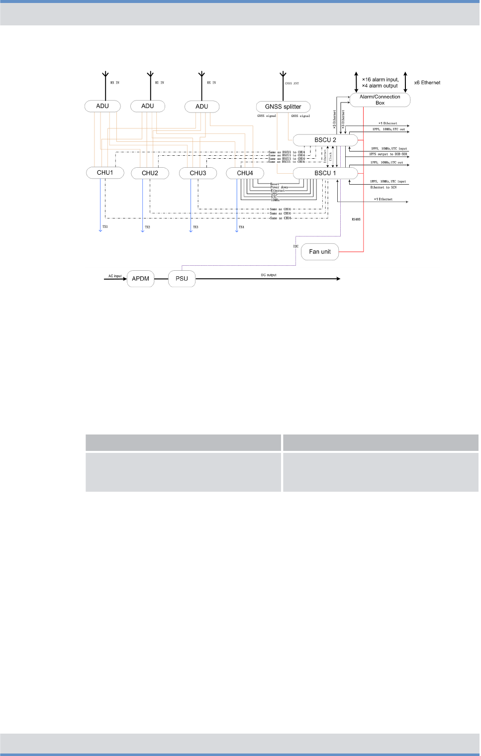
Figure 28: Internal wiring with four CHUs and external antenna coupling system
3.4.2 Antenna configurations
The following table provides an overview of the antenna configurations that are described
in the following chapters.
Overview of antenna configurations
Antenna configuration Described in
Ä
Antenna configuration with four CHUs
and external antenna coupling system
Ä
Chapter 3.4.2.1 “Antenna configuration
with four CHUs and external antenna cou-
pling system” on page 59
3.4.2.1 Antenna configuration with four CHUs and external antenna coupling system
The following figure shows the antenna configuration with four CHUs and external
antenna coupling system.
Product description
Wiring diagrams > Antenna configurations
DIB-R5 flexibleTx
57Operation Manual 90DIBR5flexibleTxOM02 - 1.2

Figure 29: Antenna configuration with four CHUs and external antenna coupling system
3.5 Redundancy options
The ACCESSNET-T IP provides numerous redundancy concepts to ensure the availa-
bility of services and features reliably even in exceptional situations. The concept of
designing system functions, function blocks, network elements and connection routes
redundantly, may be required to ensure site reliability and system reliability. Site and
system reliability refers to the capability of the network to perpetuate the operation of the
overall system, even if one site or route drops out completely or partially (due to technical
failure, natural phenomena, acts of terrorism etc.).
The system technology allows flexible network structures and scalable redundancy solu-
tions that account for the different requirements for availability and capacity within an
complete network.
If the DIB-R5 flexibleTx should be isolated from the rest of the network, it still provides
most of its features in local fallback operation. Especially security-related features like
authentication and air interface encryption are supported. Hence, DIB-R5 flexibleTx ena-
bles a fully functional fallback operation and full redundancy for the important compo-
nents transceiver (CHU), control unit (BSCU) and power supply.
The following chapters describe the available redundancy options in conjunction with
DIB-R5 flexibleTx:
n
Ä
Redundant main control channel (MCCH)
n
Ä
Carrier redundancy
n
Ä
Controller redundancy
n
Ä
Fallback operation
n
Ä
Stand-alone operation
n
Ä
Redundant VAC power supply
n
Ä
Redundant connection to the transport network
n
Ä
Redundant synchronization (GNSS, PTP)
The redundancy options can be combined with each other.
Product description
Redundancy options
DIB-R5 flexibleTx
58 Operation Manual 90DIBR5flexibleTxOM02 - 1.2

3.5.1 Redundant main control channel (MCCH)
By redundant main control channels (MCCH) the operation of a base station is guaran-
teed even if the carrier with the MCCH drops out or should be disturbed.
If the carrier that provided the main control channel last drops out, an alternative carrier
will take on this task. The MCCH is thus transferred. This transfer is made as often as the
number of carriers that are available on the base station. In this case, the replacement
carriers for the MCCH keep on sending on their original frequency, not on the frequency
of the failed carrier. This frequency change is useful especially when interfering carriers
affect the MCCH frequency that was being used up to that point such that the MCCH
does not suffer further interference after the frequency change.
Irrespective of the number of carriers, each radio cell has only one MCCH, via which the
terminals receive information, e.g. on adjacent radio cells. As a rule, the first channel of
the first carrier of a base station is used as the MCCH, the three remaining channels of
that carrier and all the channels of all the other carriers are used as voice channels or the
Packet Data service. Redundant MCCH are enabled by default and apply to all the base
stations with more than one carrier.
3.5.2 Carrier redundancy
To increase the reliability of carriers or to ensure the Base Station Function (BSF), redun-
dant carriers can be used within a base station. These spare carrier ensure the radio cov-
erage on the frequency of the failed carrier if a carrier drops out. Carrier redundancy is
mostly used in cases, in which only a few frequencies are available.
3.5.3 Controller redundancy
The controller required for operating a base station can be of redundant design. For this
purpose two BSCUs (Base Station Controller Units, BSCU) are used, where one BSCU is
in operation and the other is on standby. In the case of a failure of the active BSCU, the
standby BSCU is automatically activated and takes on its function. In this way, the opera-
tion of the base station is always ensured.
3.5.4 Fallback operation
The radio coverage of base stations is also ensured if the base station loses the connec-
tion to an IP Node (IPN) with Switching Controller Function (SCF). In this case, the base
station changes to fallback operation. In fallback operation, the base station in its radio
cell still maintains the Base Station Function (BSF). Even in fallback operation, authenti-
cation and authorization validation are ensured since the corresponding subscriber data
are stored in the base station.
The connection to other network constituents is not possible in fallback operation, the fol-
lowing services and features, however, are available locally:
nGroup calls
nIndividual calls (semi-duplex and duplex calls)
nTransmission of SDS and status messages
Product description
Redundancy options > Fallback operation
DIB-R5 flexibleTx
59Operation Manual 90DIBR5flexibleTxOM02 - 1.2

nClass 2 and class 3 air interface encryption (encrypted voice and data communica-
tion)
nAuthentication (with respect to the base station)
nPriority calls, emergency calls, pre-emptive priority calls
nQueue, depending on the priority level of the call
nRejection of a call from/to an unknown subscriber
nRejection with the reason "busy" if the subscriber is already making a call or the pri-
ority of the incoming call is minor
nConfigurable call time limit
nInactivity timer (ending semi-duplex calls after the configured inactivity time has
expired)
Fallback operation is the emergency operating mode of base stations in networks with
centralized switching architecture. The unavailability of network-wide services is signaled
to the terminals and taken into account by them during the cell selection.
3.5.5 Stand-alone operation
The radio coverage of base stations with Switching Controller Function (SCF) in networks
with distributed switching architecture continues to be ensured if they lose the connection
to all other network constituents with SCF. In this case the base station switches to stand-
alone operation.
In stand-alone operation, the base station in its radio cell will perpetuate the Base Station
Function (BSF) as well as all the other local services and gateways (Application Gateway
(AGW) and/or Packet Data Gateway (PGW)). As opposed to fallback operation, in stand-
alone operation Call Detail Records (CDR) will still be generated.
Stand-alone operation is the emergency operating mode of base stations in networks with
distributed switching architecture. The unavailability of network-wide services is signaled
to the terminals and taken into account by them during the cell selection. Depending on
the project requirements, the signaling can be switched off upon demand.
3.5.6 Redundant VAC power supply
For the reliable power supply, DIB-R5 provides two redundancy options for VAC power
supply to ensure operation of the base station at all times:
n
Ä
Redundant rectifier modules (Power Supply Module, PSM)
n
Ä
Redundant power supply lines
Both redundancy options can be combined for the highest possible reliability.
3.5.6.1 Redundant rectifier modules (Power Supply Module, PSM)
The power supply continues to be ensured through redundant rectifier modules (Power
Supply Module, PSM) and ensures the operation of DIB-R5 if one PSM should fail. The
active and the redundant PSMs are all in operation in this case and divide the load
among them. In case of a failure, the load on the remaining PSMs is increased accord-
ingly.
Product description
Redundancy options > Redundant VAC power supply
DIB-R5 flexibleTx
60 Operation Manual 90DIBR5flexibleTxOM02 - 1.2

In the combination with redundancy option "Redundant power supply lines", two PSMs
each are supplied by one power supply line.
3.5.6.2 Redundant power supply lines
The power supply continues to be ensured by a redundant power supply line on site and
secures the operation of the DIB-R5, even if a supply line should fail or the required
voltage range is underrun. This is particularly meaningful in difficult environments in
which, for example, the infrastructure on site is unreliable. With this redundancy option,
one power supply line supplies one AC Power Distribution Module (APDM) in each case.
If this redundancy option is selected, a second power supply line must be taken into
account in the site planning.
3.5.7 Redundant connection to the transport network
With the redundant connection to the transport network, the connection to all network
components continues to be ensured in case of a failure of the IT infrastructure (e.g.
router).
3.5.8 Redundant synchronization (GNSS, PTP)
The clock and time signals required for the synchronization of base stations are being
obtained in parallel via a connected GNSS antenna and as an alternative via the Preci-
sion Time Protocol (PTP). If the satellite signal should no longer be available due to
external influences, a switch is automatically made to the network time.
Product description
Redundancy options > Redundant synchronization (GNSS, PTP)
DIB-R5 flexibleTx
61Operation Manual 90DIBR5flexibleTxOM02 - 1.2

3.6 Scope of delivery
DIB-R5 flexibleTx is delivered in a compact rack. The scope of delivery varies depending
on the variant.
The variants and characteristics of the DIB-R5 flexibleTx are derived from the following
properties:
nPower supply
nCombiner
nNumber of transceivers
nFrequency range
nRedundancy options
Scope of delivery of DIB-R5 flexibleTx (per equipment or compact rack)
Designation Part number Number
DIB-R5 flexibleTx 5503.xxxx.xx 1
Connection and control
panel
Alarm/connection box (connection panel) 5502.0640.02 1
GNSS splitter 5502.0962.00 1
VAC power supply AC Power Distribution Module (APDM) 5502.0579.02 1 to 2
Power Supply Unit (PSU) 5502.1020.00 1
Power Supply Module (PSM) 5502.0910.00 1 to 4
VDC power supply DC Power Distribution Module (DPDM) 5502.0585.02 1
Divider Unit (DIU) ADU 5502.0880.xx 1 to 3
Transmitting filter (one of the
two)
DUPLEXER 5502.0862.xx 1
TX FILTER 5502.0879.xx 1
TETRA Channel Unit (CHU) 5502.0104.xx 1 to 4
Base Station Controller Unit (BSCU) 5502.0704.04 1 to 2
Fan unit 5502.0604.03 1
Backplane 5502.0656.02 1
Dummy modules/plates RX FILTER dummy module 5502.1000.00 0 to 2
CHU dummy module 5502.0985.00 0 to 3
BSCU dummy module 5502.0991.00 0 to 1
APDM dummy module 5502.0981.00 0 to 1
PSM dummy plate 5502.0991.00 0 to 3
nxx is variant-specific and, for example, dependent on the frequency range or power supply
n* with expansion rack only
Product description
Scope of delivery
DIB-R5 flexibleTx
62 Operation Manual 90DIBR5flexibleTxOM02 - 1.2

4 Operation
This chapter describes the procedure for the proper operation of the product at its site.
The work steps listed in the following table must be performed for the operation of the
product.
Overview of work steps to be performed (operation)
Work steps Described in
Ä
Switching on the DIB-R5 flexibleTx
Ä
Chapter 4.2 “Switching on
the DIB-R5 flexibleTx”
on page 66
Ä
Function tests and
operational monitoring
Ä
Checking operating states
Ä
Chapter 4.3.3 “Checking
operating states” on page 70
Ä
Checking the availability
Ä
Chapter 4.3.4 “Checking
the availability” on page 72
Ä
Function tests and GNSS
operational monitoring
Ä
Chapter 4.3.6 “Function
tests and GNSS operational
monitoring” on page 74
4.1 Safety measures and prerequisites
The following security measures and prerequisites must be observed for all activities:
nThe site must be prepared in compliance with the document "DIB-R5 flexibleTx Site
Requirements".
nThe product must have been set up/installed and connected according to the
"DIB-R5 flexibleTx Installation Manual" document.
nThe product must have been configured according to the document
"DIB-R5 flexibleTx Configuration Manual".
nThe DIB-R5 flexibleTx may be set up and commissioned only if the required environ-
mental conditions are met at all times, refer to
Ä
Table “Environmental conditions” on
page 66.
nThe safety regulations must be considered at all times, refer to
Ä
Chapter 2 “Safety
regulations” on page 13.
nObserve all other activity-based security measures and prerequisites in the work
steps in this chapter.
nThe front and rear side of the compact rack must be accessible, refer to the
"DIB-R5 flexibleTx Site Requirements" document.
Operation
Safety measures and prerequisites
DIB-R5 flexibleTx
63Operation Manual 90DIBR5flexibleTxOM02 - 1.2

Environmental conditions
Operation Temperature range
(normal)
+5 °C to +45 °C (+41 °F to
+113 °F)
Temperature range
(extreme, as per
EN 300 394-1)
-30 °C to +55 °C (-22 °F to
+131 °F)
Relative humidity 5 % to 85 % (non-con-
densing)
Degree of protection IP20
Altitude for operation (max.
altitude of site)
max. 3000 m (9842 ft)
Transport
(in original packaging)
Temperature range -40 °C to +70 °C (-40 °F to
+158 °F)
Storage
(in original packaging)
Temperature range -40 °C to +70 °C (-40 °F to
+158 °F)
4.2 Switching on the DIB-R5 flexibleTx
The product is switched on via an on/off switch on the connection and control panel. After
switching on the DIB-R5 flexibleTx, the integrated hardware components will automati-
cally start up. Connections will be enabled. All the components are started up after
approx. three to five minutes.
To switch on the product, the connections must have been made properly and the power
source at the installation site must have been switched on already. The procedure for
switching on the power source depends on the circumstances at the respective installa-
tion site.
Several on/off switches with redundant power supply lines
With redundant power supply lines (optional), the DIB-R5 flexibleTx features two on/off
switches and two separate power sources, if necessary. Each of them has to be
switched on for commissioning the product.
Switching on the DIB-R5 flexibleTx
Preparation:
nThe DIB-R5 flexibleTx must be connected with the grounding system of the power
source at the installation site.
nAll required connecting cables as well as antennas must be connected.
nThe alarm contacts must be wired.
1. Switch on the power source via the corresponding equipment at the installation site.
ðThe integrated hardware components start up.
Operation
Switching on the DIB-R5 flexibleTx
DIB-R5 flexibleTx
64 Operation Manual 90DIBR5flexibleTxOM02 - 1.2

➔ You have successfully switched on the DIB-R5 flexibleTx.
Performing function tests
Following the execution of the work steps, it is recommended to perform function tests in
order to ensure the proper mode of operation of the product.
The function tests are described in
Ä
Chapter 4.3 “Function tests and operational moni-
toring” on page 67.
4.3 Function tests and operational monitoring
After all the tasks have been performed on the product that have effects on the product
and/or its components, the proper operation of all the integrated network and hardware
components should be tested. We recommend logging the results of the test.
In addition, it is recommended to perform the tasks described in the following sections in
regular intervals during the operation.
The following table provides an overview of work steps for testing the function and for
operational monitoring.
Overview of work steps (function tests and operational monitoring)
Work steps Described in
Ä
Connecting the service computer
Ä
Chapter 4.3.2 “Con-
necting the service
computer” on page 69
Ä
Checking operating
states
Ä
Checking operating states (via
LEDs)
Ä
Chapter 4.3.3.1
“Checking operating
states (via LEDs)”
on page 70
Ä
Checking operating states
(audible check)
Ä
Chapter 4.3.3.2
“Checking operating
states (audible check)”
on page 70
Ä
Checking operating states (via
NMC-511 FaultManager)
Ä
Chapter 4.3.3.3
“Checking operating
states (via NMC-511
FaultManager)”
on page 71
Ä
Checking the availability
Ä
Chapter 4.3.4
“Checking the availa-
bility” on page 72
Operation
Function tests and operational monitoring
DIB-R5 flexibleTx
65Operation Manual 90DIBR5flexibleTxOM02 - 1.2

Work steps Described in
Ä
Checking standby carriers
‒
optional
Ä
Chapter 4.3.5
“Checking standby car-
riers
‒
optional”
on page 73
Ä
Function tests and GNSS operational monitoring
Ä
Chapter 4.3.6 “Func-
tion tests and GNSS
operational monitoring”
on page 74
Ä
Function tests and PTP operational monitoring (optional)
Ä
Chapter 4.3.7 “Func-
tion tests and PTP
operational monitoring
(optional)” on page 76
Ä
Checking external antenna coupling systems
Ä
Chapter 4.3.8
“Checking external
antenna coupling sys-
tems” on page 77
4.3.1 Work equipment for function tests
The following table provides an overview of the work equipment for function tests and
operational monitoring.
Overview of work equipment (function tests and operational monitoring)
Work step Work equipment
Checking operating states via the NMC-511
FaultManager
nconfigured NMC computer
nstraight through ethernet cable
nNMC-511 FaultManager
Checking the reachability of network ele-
ments
nconfigured NMC or service computer
nstraight through ethernet cable
Checking standby carriers NMC-511 FaultManager
Function tests and GNSS operational moni-
toring
nconfigured NMC computer
nNMC-511 FaultManager
nGNSS antenna(s)
nGNSS antenna cable
Function tests and PTP operational moni-
toring
nconfigured NMC or service computer
nNetwork tool (e.g. Wireshark)
4.3.2 Connecting the service computer
The service computer may be any computer that meets the system requirements.
Operation
Function tests and operational monitoring > Connecting the service computer
DIB-R5 flexibleTx
66 Operation Manual 90DIBR5flexibleTxOM02 - 1.2
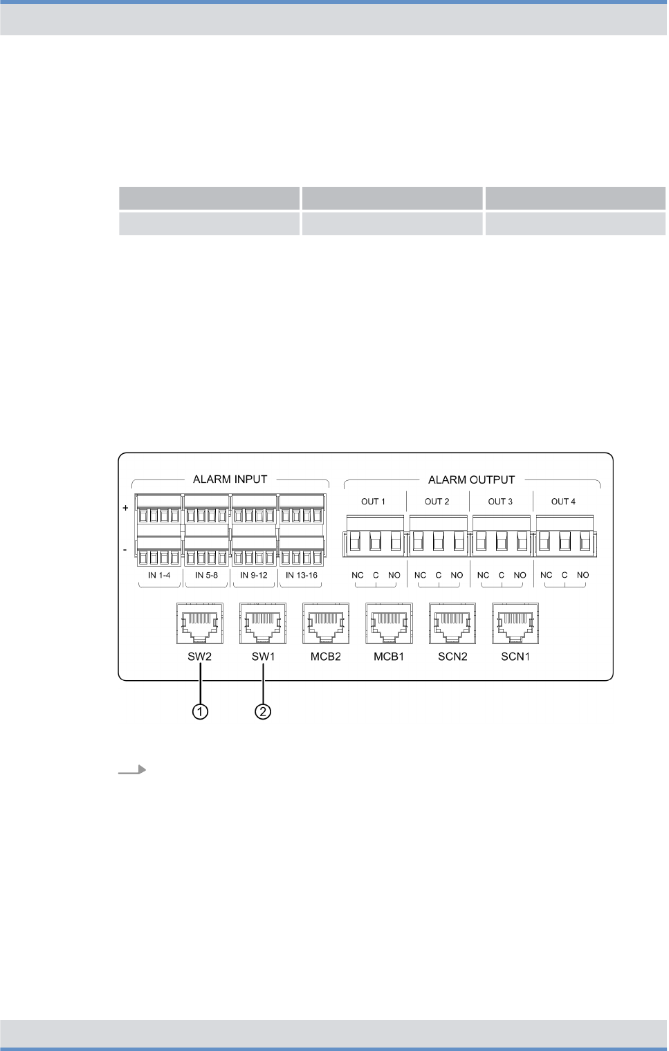
The system requirements for the service computer are described in the related product
documents, refer to the following table.
Required product documents
Product Document type Described in
Service computer Configuration Manual Chapter 2
The service computer is connected via the connection panel. The ethernet interface
"SW1" is used by default for this purpose; with controller redundancy, the ethernet inter-
face "SW2" is additionally used for the connection to the second BSCU. During the con-
nection, the service computer is automatically assigned a local service IP address for the
respective DIB-R5 flexibleTx.
Connecting the service computer
Preparation:
nThe work equipment must be available, refer to
Ä
Chapter 4.3.1 “Work equipment for
function tests” on page 66.
nThe service computer must have been started.
nThe DIB-R5 flexibleTx must be switched on.
Figure 30: Connections of the service computer (local)
Connect the ethernet cable to the connector on the DIB-R5 flexibleTx (refer to
Figure 30) and to the ethernet port of the service computer.
➔ You have successfully connected the service computer.
4.3.3 Checking operating states
You can check manually whether the product and the hardware components installed
operate properly on the respective hardware component, if indicators are available, or via
a connected NMC-511 FaultManager network management client.
Operation
Function tests and operational monitoring > Checking operating states
DIB-R5 flexibleTx
67Operation Manual 90DIBR5flexibleTxOM02 - 1.2

The following table provides an overview of the procedures for checking operating states
of the DIB-R5 flexibleTx.
Overview of the procedures for checking operating states
Work step Described in
Ä
Checking operating states (via LEDs)
Ä
Chapter 4.3.3.1 “Checking operating
states (via LEDs)” on page 70
Ä
Checking operating states (audible
check)
Ä
Chapter 4.3.3.2 “Checking operating
states (audible check)” on page 70
Ä
Checking operating states (via
NMC-511 FaultManager)
Ä
Chapter 4.3.3.3 “Checking operating
states (via NMC-511 FaultManager)”
on page 71
4.3.3.1 Checking operating states (via LEDs)
The following table provides an overview of hardware components whose LEDs can be
checked.
Checking operating states (via LEDs)
Hardware component Described in
TETRA Channel Unit (CHU)
Ä
Table “Legend: Indicators (LEDs) of the
CHU” on page 46
Base Station Controller Unit (BSCU)
Ä
Table “Legend: Indicators (LEDs) of the
BSCU” on page 49
Fan unit
Ä
Table “Legend: Indicators (LEDs) of the
fan unit” on page 52
Power Supply Module (PSM) ‒ with VAC
power supply
Ä
Table “Legend: PSM (front view)” on
page 40
4.3.3.2 Checking operating states (audible check)
Upon switching on the DIB-R5 flexibleTx, the fans briefly rotate at high speed and are
then adjusted according to the room temperature. No grinding or rattling noise should be
present at this time.
Operation
Function tests and operational monitoring > Checking operating states
DIB-R5 flexibleTx
68 Operation Manual 90DIBR5flexibleTxOM02 - 1.2

Checking operating states (audible check)
Preparation:
nThe DIB-R5 flexibleTx must be switched on.
nThe front door must be open.
Check whether grinding or rattling noise can be heard.
ðIf the corresponding noises can be heard, you must perform a fault analysis.
➔ You have successfully completed the function test.
4.3.3.3 Checking operating states (via NMC-511 FaultManager)
Using the NMC‑511 FaultManager network management client, faults occurring in an
ACCESSNET-T IP network can be detected and localized rapidly. This facilitates prompt
fault elimination.
All network constituents and connections of an ACCESSNET-T IP are monitored via the
NMC-511 FaultManager. Operating states and faults are detected by the network man-
agement system and visualized via the connected workstations, on which the NMC-511
FaultManager is installed and enabled.
The NMC-511 FaultManager displays the operating states and faults of the network con-
stituents in the respective network in an alarm status list. This makes permanent network
monitoring possible.
Checking operating statuses via the NMC-511 FaultManager requires an NMC computer
that is configured accordingly and connected with the ACCESSNET-T IP.
Besides checking the respective hardware and software components, the application
connections between the network elements should also be checked to ensure the correct
connection.
Checking the operating state (via NMC-511 FaultManager)
Preparation:
nThe NMC-511 FaultManager must have been started.
1. Use the Equipment view of the NMC-511 FaultManager to navigate to the corre-
sponding network constituent (hardware or software component).
2. Ensure that the corresponding network constituent is shown in green in the
Equipment view of the NMC-511 FaultManager.
ðIf the respective network constituent is shown in red, you must perform a fault
analysis, refer to NMC-511 FaultManager user manual.
3. Check whether a predecessor alarm status is displayed for the respective network
constituent which displays a fault that may already have existed.
ðIf the predecessor alarm status is shown in red, it is recommended to generate
a report via the Analysis perspective.
4. Navigate to the Service perspective and check whether corresponding services are
shown in green.
ðIf services are shown in red, you must perform a fault analysis, refer to
NMC-511 FaultManager user manual.
Operation
Function tests and operational monitoring > Checking operating states
DIB-R5 flexibleTx
69Operation Manual 90DIBR5flexibleTxOM02 - 1.2

5. In the Equipment view, check whether all application connections are displayed in
green.
ðIf application connections are shown in red, you must perform a fault analysis,
refer to NMC-511 FaultManager user manual.
➔ You have successfully checked the operating states.
4.3.4 Checking the availability
After network elements have been connected with an existing switch or router at the site,
it must be checked whether the respective network element can be reached via the IP
address of the BSCU. The NMC-511 FaultManager is used to check whether the IP
address can be reached. If this should not be possible, the ping command should be
used to check whether it can be reached.
IP addresses of installed components
The configured IP addresses can be displayed via the NMC-511 FaultManager in the
Properties view and are also documented in the project-specific documentation.
Checking the availability
Preparation:
nThe NMC or service computer must have been connected with the transport network.
nThe NMC-511 FaultManager must have been started.
1. Check the state of the connections in the Visualization view of the NMC-511 Fault-
Manager.
Optional work step
The work steps described below are required only if the NMC-511 FaultManager cannot
check whether the network element can be reached or if no connection exists.
2. Use the Equipment view of the NMC-511 FaultManager to navigate to the corre-
sponding network constituent (hardware or software component).
3. Change to the Properties view and record the required IP address.
4. Click on “Windows Start menu è Programs è Accessories è Command prompt”.
ðThe command prompt is displayed.
Operation
Function tests and operational monitoring > Checking the availability
DIB-R5 flexibleTx
70 Operation Manual 90DIBR5flexibleTxOM02 - 1.2

5. Enter the following command to check the reachability of the network element:
ping <xxx>
<xxx> corresponds to the IP address of the respective component within the
DIB-R5 flexibleTx.
ðThe following output is displayed (example):
C:\Users\User>ping <xxx>
Ping is executed for <xxx> with 32 bytes of data:
Response from <xxx>: Bytes=32 Time<1 ms TTL=63
Response from <xxx>: Bytes=32 Time<1 ms TTL=63
Response from <xxx>: Bytes=32 Time<1 ms TTL=63
Ping statistic for <xxx>:
Packets: Sent = 4, Received = 4, Lost = 0 (0% loss),
Approx. time information in milliseconds: Minimum = 0 ms,
maximum = 0 ms, average = 0 ms
➔ You have successfully checked the availability.
4.3.5 Checking standby carriers ‒ optional
DIB-R5 flexibleTx optionally provides the redundancy option "Carrier redundancy" with
which failed carriers can be replaced.
As a preventive maintenance task, it is recommended to check the function of the
standby carriers at regular intervals, refer to
Ä
Chapter 7.2 “Periodical visual inspections”
on page 84. This is done via the NMC-511 FaultManager.
Checking standby carriers
Preparation:
nThe respective DIB-R5 flexibleTx must be in operation.
nThe NMC-511 FaultManager must have been started.
1. Select the corresponding operational carrier in the Equipment or Visualization view
of the NMC-511 FaultManager.
2. Right-click on the selected carriers to display the context menu.
ðThe context menu will be displayed.
Availability of maintenance functions
Not all the maintenance functions can be used for all the network constituents.
Maintenance functions that cannot be performed for the time being will be dis-
played in grey and cannot be selected.
Operation
Function tests and operational monitoring > Checking standby carriers ‒ optional
DIB-R5 flexibleTx
71Operation Manual 90DIBR5flexibleTxOM02 - 1.2

3. In the context menu, click on the System lock maintenance function.
ðThe corresponding carriers are excluded from functional operation and identi-
fied in the Equipment view with the "Person" icon (operationally locked by the
user).
Existing standby carriers are enabled.
4. In the NMC-511 FaultManager, check in the Equipment view of the Equipment
perspective whether the standby carriers become active and do not report alarm.
5. Wait at least 5 minutes before releasing locked operational carriers via the System
unlock maintenance function.
ðThe system locking of operational carriers has been revoked.
Standby carriers are switched back to their original status.
➔ You have successfully checked the standby carriers.
4.3.6 Function tests and GNSS operational monitoring
The following chapters describe procedures for function tests and the operational moni-
toring concerning the GNSS functionality of the DIB-R5 flexibleTx.
4.3.6.1 Checking the installation site of the GNSS antenna
To prevent damage, e.g. caused by insufficient guarding and/or fastening, the installation
site of the GNSS antenna should be checked following the installation of the GNSS
antenna.
Checking the installation site of the GNSS antenna
Preparation:
nThe installation and connection of the GNSS antenna must have been completed.
1. Check the installation site of the GNSS antenna for proper condition, such as the
nfastening of the antenna mast,
nfastening of the GNSS antenna,
ncable routing.
Operation
Function tests and operational monitoring > Function tests and GNSS operational monitoring
DIB-R5 flexibleTx
72 Operation Manual 90DIBR5flexibleTxOM02 - 1.2

Circumferential range of vision (angle of unobstructed visibility of the sky) of the
GNSS antenna.
A good circumferential range of vision (angle of unobstructed visibility of the sky
according to the recommendations of the manufacturer) must be maintained to ensure
proper reception of the GNSS antenna. The angle of the GNSS antenna supplied is 90°.
When using a third-party GNSS antenna, heed the corresponding documentation sup-
plied with the GPS antenna.
2. Check the circumferential range of vision of the GNSS antenna.
➔ The visual inspection has thus been completed.
4.3.6.2 GNSS operational monitoring (via NMC-511 FaultManager)
The function of the GNSS receiver and the detectable GNSS satellites are monitored by
the DIB-R5 flexibleTx based on the GNSS data received.
Using the NMC‑511 FaultManager network management client, faults occurring in an
ACCESSNET-T IP network can be detected and localized rapidly. This facilitates prompt
fault elimination.
All network constituents and connections of an ACCESSNET-T IP are monitored via the
NMC-511 FaultManager. Operating states and faults are detected by the network man-
agement system and visualized via the connected workstations, on which the NMC-511
FaultManager is installed and enabled.
The NMC-511 FaultManager displays the operating states and faults of the network con-
stituents in the respective network in an alarm status list. This makes permanent network
monitoring possible.
The procedures for this purpose are described in corresponding documents, refer to the
following table.
Required product documents
Product Document type
NMC-511 FaultManager User manual
In the NMC-511 FaultManager the operating conditions and errors on network constitu-
ents are represented by so-called alarm objects.
Alarm objects provide alarms/statuses for properties of hardware and software compo-
nents. In addition, alarm objects contain information that aids in the context of fault man-
agement in the evaluation, localization and removal of errors.
Alarm objects always have an alarm status, alarm status changes are notified via events
and visualized in the NMC-511 FaultManager.
Operation
Function tests and operational monitoring > Function tests and GNSS operational monitoring
DIB-R5 flexibleTx
73Operation Manual 90DIBR5flexibleTxOM02 - 1.2

GNSS module – Possible messages
No. Alarm object (NMC-511 FaultManager) Meaning
1GNSS antenna status Status of the GNSS antenna con-
nection
2Communication (GNSS) Status of communication with the
GNSS module
4.3.7 Function tests and PTP operational monitoring (optional)
The following chapters describe procedures for function tests and the operational moni-
toring concerning the PTP functionality of the DIB-R5 flexibleTx.
4.3.7.1 PTP operational monitoring (via NMC-511 FaultManager)
The function of the PTP receiver is monitored between the DIB-R5 flexibleTx and the
grandmaster clock based on the status of the Precision Time Protocol (PTP).
The procedures for this purpose are described in corresponding documents, refer to the
following table.
Required product documents
Product Document type
NMC-511 FaultManager User manual
In the NMC-511 FaultManager the operating conditions and errors on network constitu-
ents are represented by so-called alarm objects.
Alarm objects provide alarms/statuses for properties of hardware and software compo-
nents. In addition, alarm objects contain information that aids in the context of fault man-
agement in the evaluation, localization and removal of errors.
Alarm objects always have an alarm status, alarm status changes are notified via events
and visualized in the NMC-511 FaultManager.
PTP module – Possible messages
No. Alarm object (NMC-511 FaultManager) Meaning
1PTP connection Connection status to grandmaster
clock
2PTP synchronization Status of PTP synchronization with
grandmaster clock
Operation
Function tests and operational monitoring > Function tests and PTP operational monitoring (optional)
DIB-R5 flexibleTx
74 Operation Manual 90DIBR5flexibleTxOM02 - 1.2

4.3.8 Checking external antenna coupling systems
The operator alone is responsible for checking external antenna coupling systems,
insofar as this is not a contractual component of the Hytera Mobilfunk GmbH. An
appointed installer of the antenna coupling system is responsible for conducting all the
necessary measures and for compliance with the corresponding specifications.
Operation
Function tests and operational monitoring > Checking external antenna coupling systems
DIB-R5 flexibleTx
75Operation Manual 90DIBR5flexibleTxOM02 - 1.2

Operation
Function tests and operational monitoring > Checking external antenna coupling systems
DIB-R5 flexibleTx
76 Operation Manual 90DIBR5flexibleTxOM02 - 1.2

5 Service interruption
This chapter describes the procedure for the service interruption of the product.
A service interruption may be required in the following cases:
nWork on an open compact rack
nEnd of operation
nMalfunction
nIntegration of further components
Possible restrictions for the operation
If a product is taken out of service, the operation of other parts in the radio network may
be impaired as well. Discuss this problem with your service partner to obtain detailed
information on risks and on recommended procedures.
5.1 Shutting down hardware components
The installed hardware components CHU and BSCU operate with different software com-
ponents that should be shut down properly. For this reason, these hardware components
must be shut down before switching off the DIB-R5 flexibleTx.
The following table provides an overview of the order in which the hardware components
should be shut down.
Shutting down hardware components (order)
Order Hardware component
1 BSCU (standby) ‒ optional
With redundant BSCUs (controller redundancy), the BSCU in standby
mode must be shut down first to prevent a switchover of the BSCUs.
The operating status of the BSCU is indicated via LEDs, refer to
Ä
Table “Legend: Indicators (LEDs) of the BSCU” on page 49.
2 BSCU (operational)
Shutting down the CHU
All installed CHUs are automatically shut down at the same time when shutting down
the BSCUs without standby BSCU (controller redundancy). The CHUs do not have to be
shut down individually except for service and maintenance purposes.
Service interruption
Shutting down hardware components
DIB-R5 flexibleTx
77Operation Manual 90DIBR5flexibleTxOM02 - 1.2

Shutting down hardware components
Press and hold down the power button at the hardware component for more than 5
seconds to shut it down.
ðThe software components are being shut down. This may take approx. 5 to 20
seconds.
BSCU: The hardware component is properly shut down if the "RUN" LED
flashes quickly.
CHU: The hardware component is properly shut down if the "RUN" LED is off.
➔ You have successfully shut down the hardware components.
5.2 Switching off the DIB-R5 flexibleTx
The procedure for switching off the DIB-R5 flexibleTx is described below.
Several on/off switches with redundant power supply lines
With redundant power supply lines (optional), the DIB-R5 flexibleTx features two on/off
switches and two separate power sources, if necessary. Each of them has to be
switched off for the service interruption of the product.
Switching off the DIB-R5 flexibleTx
Preparation:
nThe installed hardware components must have been shut down, refer to
Ä
Chapter
5.1 “Shutting down hardware components” on page 77.
1. Set the on/off switch to the switch position "OFF", refer to Figure 8.
ðThe integrated hardware components are switched off.
2. Switch off the power source at the site. Alternatively you can switch off the fuse of
the sub-distribution.
Risk of electric shock
Ensure by means of switch interlock that a source of electrical power cannot be
switched on unintentionally by an unauthorized third person.
3. Check whether all LED displays are inactive.
➔ You have successfully switched off the DIB-R5 flexibleTx.
Service interruption
Switching off the DIB-R5 flexibleTx
DIB-R5 flexibleTx
78 Operation Manual 90DIBR5flexibleTxOM02 - 1.2

6 Recommissioning
To recommission the product, you either have to connect the compact rack to the power
source or switch it on, depending on the connection variant.
Recommissioning
For the recommissioning of the DIB-R5 flexibleTx, proceed as described in
Ä
Chapter
4.2 “Switching on the DIB-R5 flexibleTx” on page 64 .
Recommissioning
DIB-R5 flexibleTx
79Operation Manual 90DIBR5flexibleTxOM02 - 1.2

Recommissioning
DIB-R5 flexibleTx
80 Operation Manual 90DIBR5flexibleTxOM02 - 1.2

7 Maintenance
To ensure the proper operation of products, maintenance tasks and periodical visual
inspections are required.
The products have been designed for permanent and unsupervised operation. Neverthe-
less you have to perform checks every now and then. When doing so, you can detect and
remove dirt in the vicinity of or within equipment racks, so the air supply and heat dissipa-
tion of the products is always ensured.
Possible restrictions
Depending on the maintenance tasks and redundancy options, not all functions and fea-
tures may be available for the duration of the maintenance tasks.
The current state of the hardware components can be monitored via an NMC-511 Fault-
Manager. For additional information about the NMC-511 FaultManager, refer to the corre-
sponding product documentation.
7.1 Maintenance tasks
The required activities for maintaining the product are listed below. The maintenance
tasks must be performed in the intervals specified to ensure the proper operation of the
product. Contaminations can, for example, impede the air supply and heat dissipation
and negatively impact operation.
Maintenance tasks
Task/s Interval/s
Replacing the fan after 30 000 operating hours
Replacing the air filter mat depends on the environmental conditions
Replacing the BSCU battery every 10 years
Early fan replacement
Dependent on the environmental conditions at the installation site, the fan may have to
be replaced earlier. For this reason, please comply with the following recommended
visual inspections and intervals.
Maintenance
Maintenance tasks
DIB-R5 flexibleTx
81Operation Manual 90DIBR5flexibleTxOM02 - 1.2

7.2 Periodical visual inspections
The table below lists the recommended tasks for maintaining the products. The visual
inspections should be performed in the intervals specified to be able to respond in due
time, e.g. in the case of changes at the site that may result in improper operation.
The specified intervals refer to the operation within the defined environmental conditions,
refer to
Ä
Table “Environmental conditions” on page 64.
Shorter intervals may be required
Depending on the respective environmental conditions at the site of the product, shorter
intervals may be required.
We recommend logging the results of the test.
Tasks and intervals for visual inspections
Task/s Interval/s
Site inspection based on the document "Site Requirements
DIB-R5 flexibleTx", e.g. the inspection of the:
nGrounding equipment
nPower supply connector
nTETRA antennas
nInstallation location of the GNSS antenna
nCondition and fit of all supply lines, renew if necessary
nConnections between two DIB-R5 flexibleTx ‒ with
expansion rack only
nUpon site changes
nOnce every year
Check the condition of the product with respect to:
nOperational readiness (checking operating states)
nDirt and dust accumulations on and in the compact rack,
remove if necessary
nDegree of contamination of contact pins, remove dirt if
necessary
nCheck the fan unit for proper operation; replace the air
filter mat as required
Once every year
Checking function of external alarms – if wired Once every year
Checking standby carriers – if available Once every year
Checking external antenna coupling systems The use of external
antenna coupling sys-
tems is project specific.
The network operator
alone is responsible for
properly checking
external antenna cou-
pling systems.
Maintenance
Periodical visual inspections
DIB-R5 flexibleTx
82 Operation Manual 90DIBR5flexibleTxOM02 - 1.2

8 Troubleshooting
Troubleshooting via the network management system (NMS)
The NMC-511 FaultManager can be used to detect faults within the ACCESSNET-T IP.
This is done via a NMC computer that has been configured accordingly.
The troubleshooting via the NMC-511 FaultManager should be performed prior to the
troubleshooting on site (e.g. at sites of network elements). It can provide information
whether a site must actually be visited.
The following table lists possible problems, causes and troubleshooting measures.
Troubleshooting
Problem Possible cause Troubleshooting
Base station cannot be
reached/switched on
On/off switch in switch position
"OFF"
Set on/off switch to switch position "ON"
Power supply at site not
operational
Check fuse
Check distribution box or mains socket
Check power supply cable
Cable connection defective Check internal wiring
Check cables
APDM/DPDM defective Check fuse
Check wiring
Carry out the visual inspection
Check operating state via
NMC-511 FaultManager
PSU/PSM defective ‒ with VAC
power supply
Check operating states via LEDs
Check operating state via
NMC-511 FaultManager
Ethernet connection defective Check operating state via
NMC-511 FaultManager
Check reachability with ping
Connection to transport net-
work defective (stand-alone or
fallback operation)
Cable connection defective Check operating state via LEDs on
switch/router
Check internal wiring
Check ethernet cable
Troubleshooting
DIB-R5 flexibleTx
83Operation Manual 90DIBR5flexibleTxOM02 - 1.2

Problem Possible cause Troubleshooting
Switch/router defective Check operating state via LEDs on
switch/router
Call setup/registration not pos-
sible
Transmitting/receiving antenna
defective
Check antenna
Cable connection defective Check wiring of antenna(s) incl. antenna
cable
Check internal wiring
Carrier disabled Check status of carrier in the NMC-511
FaultManager
Carrier incorrectly configured Check configuration in the NMC-515
ConfigurationManager
Carrier defective Check status of carrier in the NMC-511
FaultManager and replace as required
No subscriber data available
on the base station
Check status in the NMC-511 FaultMan-
ager and, if necessary, in the NMC-515
ConfigurationManager
License for use not available Check status in the NMC-511 FaultMan-
ager
Subscriber unknown Check subscriber configuration in the
NMC-512 SubscriberManager
No authorization for call serv-
ices
Terminal incorrectly configured Check configuration of terminal
Terminal defective Check terminal
No GNSS signal GNSS antenna defective Check antenna
No unobstructed visibility of
the sky
Checking the installation site of the
GNSS antenna
Cable connection defective Check antenna cable and plug connec-
tions
BSCU/CHU not ready for
operation
Module not correctly inserted Check seating of the module (completely
inserted and flush with the other mod-
ules)
Check locking mechanism of clips and
engage correctly as necessary
Check mounting screws and tighten as
necessary
Electrical connection to back-
plane defective
Insert module correctly
PSU/PSM defective ‒ with VAC
power supply
Check PSU/PSM
Troubleshooting
DIB-R5 flexibleTx
84 Operation Manual 90DIBR5flexibleTxOM02 - 1.2

Problem Possible cause Troubleshooting
"ALM" LED is on Checking operating state in the NMC-511
FaultManager
Restarting the base station (duration
approx. three to five minutes)
BSCU, CHU defective Electrical connection to back-
plane defective
Check connection to backplane
Power supply missing Check power supply
Fan unit not (completely)
operational
Electrical connection to back-
plane defective
Check connection to backplane
PSU/PSM defective ‒ with VAC
power supply
Check PSU/PSM
"ALM" LED is on Checking operating state in the NMC-511
FaultManager
Check DIP switches at the rear side of
the fan unit
"FAN 1-6" LED flashes Checking operating state in the NMC-511
FaultManager
Check fan
Troubleshooting
DIB-R5 flexibleTx
85Operation Manual 90DIBR5flexibleTxOM02 - 1.2

Troubleshooting
DIB-R5 flexibleTx
86 Operation Manual 90DIBR5flexibleTxOM02 - 1.2

9 Index
A
Antenna coupling system
DIB-R5............................................................ 29
Authentication...................................................... 59
Availability................................................ 58, 59, 60
B
Base station
DIB-R5............................................................ 23
C
Carrier redundancy........................................ 59, 71
CDR (Call Detail Records)................................... 60
Centralized switching architecture....................... 59
Checking
Availability....................................................... 70
External antenna coupling systems................ 75
GNSS.............................................................. 73
GNSS antenna installation site....................... 72
LEDs............................................................... 68
Operating states (audible check).................... 68
Operating states (via NMC-511 FaultMan-
ager)................................................................ 69
PTP................................................................. 74
Standby carriers.............................................. 71
Connecting
Service computer............................................ 67
Connecting the service computer......................... 67
Controller redundancy.................................... 59, 66
D
Databases
NDB-511................................................... 69, 73
DIB-R5................................................................. 23
Switching off.................................................... 78
Switching on.................................................... 64
Distributed switching architecture........................ 60
E
Emergency operating mode
Fallback operation........................................... 59
Stand-alone operation..................................... 60
External antenna coupling systems..................... 15
F
Fallback, refer to Fallback operation.................... 59
Fallback operation.......................................... 58, 59
Fault management......................................... 69, 73
FCAPS
Fault management.................................... 69, 73
Function tests....................................................... 65
Checking external antenna coupling systems. 75
Checking GNSS.............................................. 73
Checking LEDs............................................... 68
Checking operating states (audible check)..... 68
Checking PTP................................................. 74
Checking standby carriers.............................. 71
Checking the availability................................. 70
Checking the installation site of the GNSS
antenna........................................................... 72
Checking the operating state (via
NMC-511 FaultManager)................................ 69
Work equipment.............................................. 66
G
GNSS antenna..................................................... 72
GNSS signal......................................................... 49
M
Maintenance......................................................... 81
Maintenance tasks.......................................... 81
Visual inspections........................................... 82
MCCH (Main Control Channel)............................ 59
N
Network management clients
NMC-511 FaultManager..................... 69, 73, 83
NMC computer..................................................... 83
R
Redundancy
Carrier....................................................... 59, 71
Controller.................................................. 59, 66
MCCH (Main Control Channel)....................... 59
Redundancy concept........................................... 58
Index
DIB-R5 flexibleTx
87Operation Manual 90DIBR5flexibleTxOM02 - 1.2

S
Service computer................................................. 66
Service interruption.............................................. 77
Service IP address............................................... 66
Shutdown
BSCU.............................................................. 77
CHU................................................................ 77
Shutting down hardware components.................. 77
Stand-alone operation.......................................... 60
Standby................................................................ 59
Standby carriers................................................... 71
Subscriber data.................................................... 59
Support information.............................................. 12
Switching architecture
centralized....................................................... 59
distributed....................................................... 60
Switching off
DIB-R5............................................................ 78
Switching on
DIB-R5............................................................ 64
Switch interlock.................................................... 78
T
Troubleshooting................................................... 83
Index
DIB-R5 flexibleTx
88 Operation Manual 90DIBR5flexibleTxOM02 - 1.2