Hytera Mobilfunk TIB500400 TETRA Indoor Base Transceiver User Manual DIB 500 R4 1 Site Requirements PV 08 01 xx

Hytera Mobilfunk GmbH TETRA Indoor Base Transceiver DIB 500 R4 1 Site Requirements PV 08 01 xx

Contents

User Manual II

90DIB500R41SR_FCC02 – 99.1Secure CommunicationsSite RequirementsDIB-500 R4.1Digital Indoor Base StationSite RequirementsPV 08.01.xx
DIB-500 R4.1II Site Requirements 90DIB500R41SR_FCC02 – 99.1© 2011 Rohde & Schwarz Professional Mobile Radio GmbH31848 Bad Münder, GermanyPrinted in Germany - Subject to change - Data without tolerance limits is not binding.Encryption components are subject to German export regulations.
Site Requirements 90DIB500R41SR_FCC02 – 99.1  IIIDIB-500 R4.1 Digital Indoor Base StationTable of contents1 Notes on the document  . . . . . . . . . . . . . . . . . . . . . . . . . . . . . . . . . . . .71.1 Objectives of the document   . . . . . . . . . . . . . . . . . . . . . . . . . . . . . . . . . . . . . 71.2 Intended audience of the document . . . . . . . . . . . . . . . . . . . . . . . . . . . . . . . 71.3 Validity of the document  . . . . . . . . . . . . . . . . . . . . . . . . . . . . . . . . . . . . . . . . 81.4 Further applicable documents  . . . . . . . . . . . . . . . . . . . . . . . . . . . . . . . . . . . 91.5 Support information . . . . . . . . . . . . . . . . . . . . . . . . . . . . . . . . . . . . . . . . . . . 102 Safety regulations   . . . . . . . . . . . . . . . . . . . . . . . . . . . . . . . . . . . . . . .112.1 Safety instructions and declaration of conformity  . . . . . . . . . . . . . . . . . . 112.1.1 Safety instructions and declaration of conformity for Europe . . . . . . . . . . . . . 112.1.2 Safety instructions and declaration of conformity for North America  . . . . . . . 132.2 Intended use  . . . . . . . . . . . . . . . . . . . . . . . . . . . . . . . . . . . . . . . . . . . . . . . . . 132.3 Safety measures . . . . . . . . . . . . . . . . . . . . . . . . . . . . . . . . . . . . . . . . . . . . . . 142.3.1 Authorised personnel  . . . . . . . . . . . . . . . . . . . . . . . . . . . . . . . . . . . . . . . . . . . 142.3.2 Electromagnetic compatibility . . . . . . . . . . . . . . . . . . . . . . . . . . . . . . . . . . . . . 152.3.2.1 Electromagnetic compatibility for Europe . . . . . . . . . . . . . . . . . . . . . . . . . . . . 152.3.2.2 Electromagnetic compatibility for North America  . . . . . . . . . . . . . . . . . . . . . . 153 Product description  . . . . . . . . . . . . . . . . . . . . . . . . . . . . . . . . . . . . . .173.1 Antenna coupling variants   . . . . . . . . . . . . . . . . . . . . . . . . . . . . . . . . . . . . . 184 Requirements concerning the operation room  . . . . . . . . . . . . . . . . 194.1 Infrastructure  . . . . . . . . . . . . . . . . . . . . . . . . . . . . . . . . . . . . . . . . . . . . . . . . 194.1.1 General requirements   . . . . . . . . . . . . . . . . . . . . . . . . . . . . . . . . . . . . . . . . . . 194.1.2 Requirements concerning the base  . . . . . . . . . . . . . . . . . . . . . . . . . . . . . . . . 204.1.3 Required space   . . . . . . . . . . . . . . . . . . . . . . . . . . . . . . . . . . . . . . . . . . . . . . . 204.1.3.1 Required space for the equipment rack/s of the product  . . . . . . . . . . . . . . . . 20
DIB-500 R4.1IV Site Requirements 90DIB500R41SR_FCC02 – 99.14.1.3.2 Required space for the uninterruptible power supply/supplies (UPS)  . . . . . . 224.1.4 Requirements for external antenna coupling system – only FlexibleTx variant  . 224.1.5 Preparing the antenna system  . . . . . . . . . . . . . . . . . . . . . . . . . . . . . . . . . . . . 244.1.6 Adjustment of the GPS antenna . . . . . . . . . . . . . . . . . . . . . . . . . . . . . . . . . . . 254.2 Environment  . . . . . . . . . . . . . . . . . . . . . . . . . . . . . . . . . . . . . . . . . . . . . . . . . 264.2.1 Operating temperature  . . . . . . . . . . . . . . . . . . . . . . . . . . . . . . . . . . . . . . . . . . 264.2.2 Humidity  . . . . . . . . . . . . . . . . . . . . . . . . . . . . . . . . . . . . . . . . . . . . . . . . . . . . . 274.2.3 Dust concentration  . . . . . . . . . . . . . . . . . . . . . . . . . . . . . . . . . . . . . . . . . . . . . 274.3 Grounding and overvoltage protection  . . . . . . . . . . . . . . . . . . . . . . . . . . . 284.3.1 Overvoltage protection of the equipment rack (VAC/VDC)   . . . . . . . . . . . . . . 284.3.2 Overvoltage protection of the voltage supply (VAC)   . . . . . . . . . . . . . . . . . . . 294.3.3 Overvoltage protection of the supply lines  . . . . . . . . . . . . . . . . . . . . . . . . . . . 305 Requirements concerning the electrical system . . . . . . . . . . . . . . . 315.1 Cable requirements and cable specifications  . . . . . . . . . . . . . . . . . . . . . . 315.1.1 General cable requirements . . . . . . . . . . . . . . . . . . . . . . . . . . . . . . . . . . . . . . 315.1.2 Cable specifications for the data and RF cables  . . . . . . . . . . . . . . . . . . . . . . 325.2 Voltage supply  . . . . . . . . . . . . . . . . . . . . . . . . . . . . . . . . . . . . . . . . . . . . . . . 325.2.1 Voltage supply (VDC) . . . . . . . . . . . . . . . . . . . . . . . . . . . . . . . . . . . . . . . . . . . 335.2.1.1 Voltage supply connector (VDC)  . . . . . . . . . . . . . . . . . . . . . . . . . . . . . . . . . . 335.2.1.2 Cable specifications of voltage supply cables (VDC) . . . . . . . . . . . . . . . . . . . 345.2.1.3 Fuse protection (VDC)  . . . . . . . . . . . . . . . . . . . . . . . . . . . . . . . . . . . . . . . . . . 355.2.2 Voltage supply (VAC) . . . . . . . . . . . . . . . . . . . . . . . . . . . . . . . . . . . . . . . . . . . 365.2.2.1 Voltage supply connector (VAC)   . . . . . . . . . . . . . . . . . . . . . . . . . . . . . . . . . . 365.2.2.2 Cable specifications of voltage supply cables (VAC)  . . . . . . . . . . . . . . . . . . . 375.2.2.3 Fuse protection (VAC)  . . . . . . . . . . . . . . . . . . . . . . . . . . . . . . . . . . . . . . . . . . 376 Requirements concerning the transport network . . . . . . . . . . . . . . 39
Site Requirements 90DIB500R41SR_FCC02 – 99.1  7DIB-500 R4.1 Notes on the documentObjectives of the document1 Notes on the documentThis chapter provides information on using the document. It also provides information on the requirements for using the product.1.1 Objectives of the documentThe present document describes the site requirements of all the available variants of the product. All the requirements described in the present document must be met to ensure intended use of the product at your site / in your service room.The service room must have been equipped as required before the product is installed in this room.The present document describes the following site requirements:|Requirements for the Service Room|Electrical System RequirementsUnintended UseIf the location / service room of the product does not meet the requirements detailed below, the product is not used as intended. The plant operator is responsible for the resulting impairment of the operation or damage to the product. For this reason, comply with all the requirements specified below.1.2 Intended audience of the documentThe present document reverts to all the persons, who|determine, equip and prepare the installation site of the product.|operate the product.Use within the scope of site inspection/acceptanceThe present document can be used as a basis for the site inspection and acceptance.Each person commissioned with performing the tasks mentioned above with or on the system must have read and understood the present document and the associated accompanying documentation.
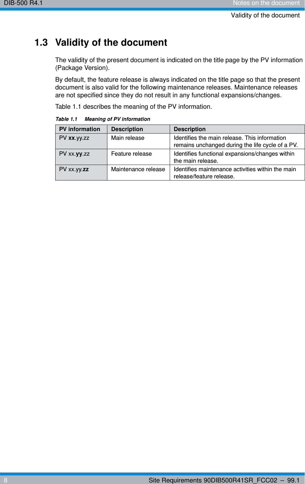
DIB-500 R4.1 Notes on the documentValidity of the document8Site Requirements 90DIB500R41SR_FCC02 – 99.11.3 Validity of the documentThe validity of the present document is indicated on the title page by the PV information (Package Version). By default, the feature release is always indicated on the title page so that the present document is also valid for the following maintenance releases. Maintenance releases are not specified since they do not result in any functional expansions/changes.Table 1.1 describes the meaning of the PV information.Table 1.1  Meaning of PV informationPV information Description DescriptionPV xx.yy.zz Main release Identifies the main release. This information remains unchanged during the life cycle of a PV.PV xx.yy.zz Feature release Identifies functional expansions/changes within the main release.PV xx.yy.zz Maintenance release Identifies maintenance activities within the main release/feature release.
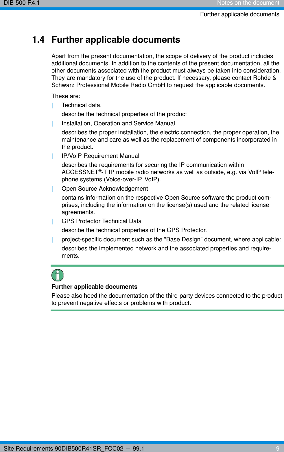
Site Requirements 90DIB500R41SR_FCC02 – 99.1  9DIB-500 R4.1 Notes on the documentFurther applicable documents1.4 Further applicable documentsApart from the present documentation, the scope of delivery of the product includes additional documents. In addition to the contents of the present documentation, all the other documents associated with the product must always be taken into consideration. They are mandatory for the use of the product. If necessary, please contact Rohde & Schwarz Professional Mobile Radio GmbH to request the applicable documents.These are:|Technical data,describe the technical properties of the product|Installation, Operation and Service Manualdescribes the proper installation, the electric connection, the proper operation, the maintenance and care as well as the replacement of components incorporated in the product.|IP/VoIP Requirement Manualdescribes the requirements for securing the IP communication within ACCESSNET®-T IP mobile radio networks as well as outside, e.g. via VoIP tele-phone systems (Voice-over-IP, VoIP).|Open Source Acknowledgementcontains information on the respective Open Source software the product com-prises, including the information on the license(s) used and the related license agreements.|GPS Protector Technical Datadescribe the technical properties of the GPS Protector.|project-specific document such as the "Base Design" document, where applicable:describes the implemented network and the associated properties and require-ments.Further applicable documentsPlease also heed the documentation of the third-party devices connected to the product to prevent negative effects or problems with product.
DIB-500 R4.1 Notes on the documentSupport information10 Site Requirements 90DIB500R41SR_FCC02 – 99.11.5 Support informationIf you have any questions or suggestions regarding Rohde & Schwarz Professional Mobile Radio GmbH products, please contact your local service partner responsible or the Rohde & Schwarz Professional Mobile Radio GmbH Support Team directly.For a fast and cost-efficient solution of technical problems during the operation of your ACCESSNET®-T IP network, Rohde & Schwarz Professional Mobile Radio GmbH offers support contracts upon request. For information on this topic, please also revert to our responsible service partner or directly to Rohde & Schwarz Professional Mobile Radio GmbH.Product training courses assist you in making use of the full scope of features and capa-bilities of your ACCESSNET®-T IP network. For information on the training program of Rohde & Schwarz Professional Mobile Radio GmbH, please revert to our responsible service partner, to Rohde & Schwarz Professional Mobile Radio GmbH or directly to Rohde & Schwarz.Rohde & Schwarz Professional Mobile Radio GmbHFritz-Hahne-Straße 7D-31848 Bad MünderGermanyTelephone:+49 (0)5042/9 98-0Fax: +49 (0)5042/9 98-105www.pmr.rohde-schwarz.com
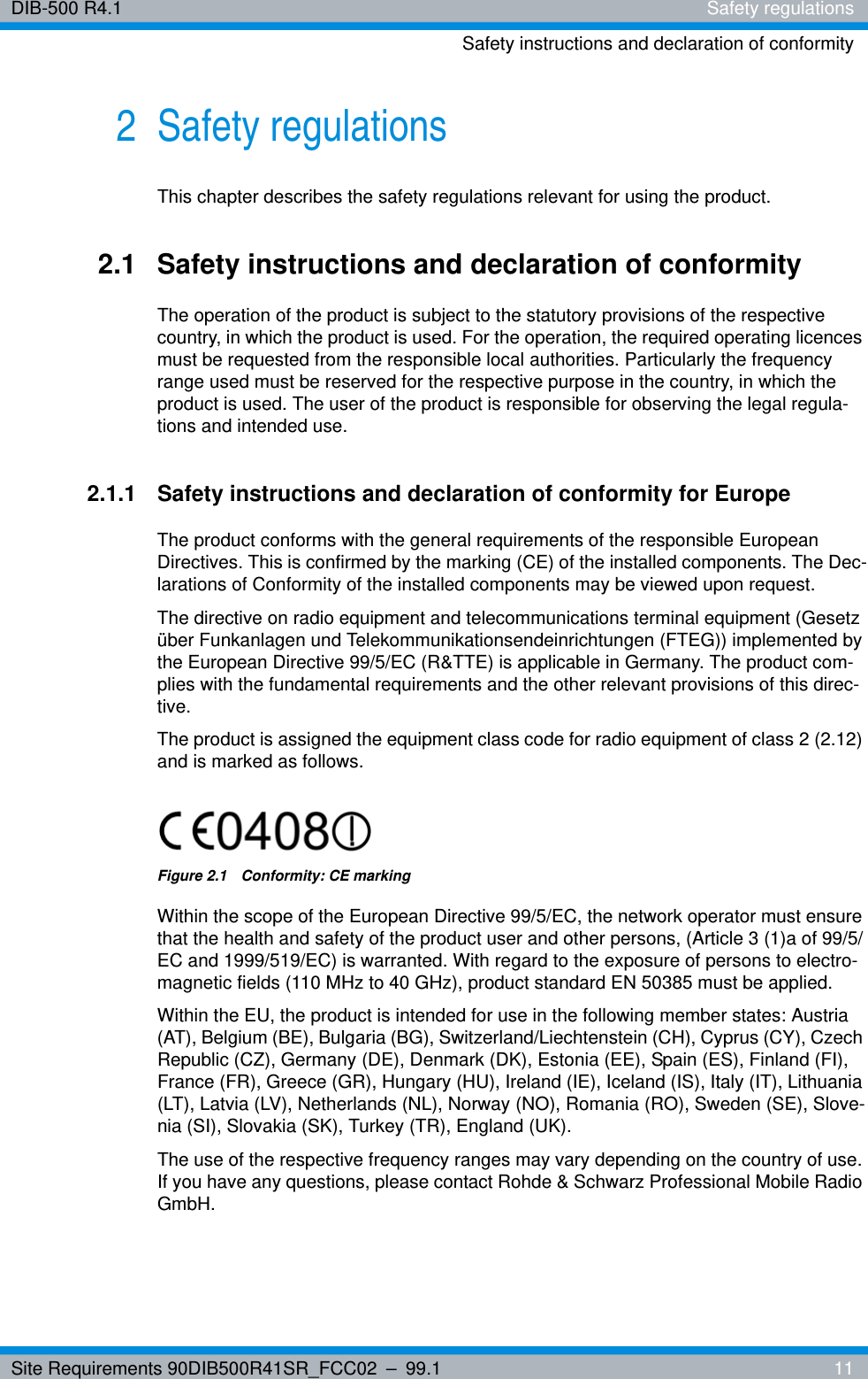
Site Requirements 90DIB500R41SR_FCC02 – 99.1  11DIB-500 R4.1 Safety regulationsSafety instructions and declaration of conformity2 Safety regulationsThis chapter describes the safety regulations relevant for using the product.2.1 Safety instructions and declaration of conformityThe operation of the product is subject to the statutory provisions of the respective country, in which the product is used. For the operation, the required operating licences must be requested from the responsible local authorities. Particularly the frequency range used must be reserved for the respective purpose in the country, in which the product is used. The user of the product is responsible for observing the legal regula-tions and intended use.2.1.1 Safety instructions and declaration of conformity for EuropeThe product conforms with the general requirements of the responsible European Directives. This is confirmed by the marking (CE) of the installed components. The Dec-larations of Conformity of the installed components may be viewed upon request.The directive on radio equipment and telecommunications terminal equipment (Gesetz über Funkanlagen und Telekommunikationsendeinrichtungen (FTEG)) implemented by the European Directive 99/5/EC (R&TTE) is applicable in Germany. The product com-plies with the fundamental requirements and the other relevant provisions of this direc-tive.The product is assigned the equipment class code for radio equipment of class 2 (2.12) and is marked as follows.Figure 2.1  Conformity: CE markingWithin the scope of the European Directive 99/5/EC, the network operator must ensure that the health and safety of the product user and other persons, (Article 3 (1)a of 99/5/EC and 1999/519/EC) is warranted. With regard to the exposure of persons to electro-magnetic fields (110 MHz to 40 GHz), product standard EN 50385 must be applied.Within the EU, the product is intended for use in the following member states: Austria (AT), Belgium (BE), Bulgaria (BG), Switzerland/Liechtenstein (CH), Cyprus (CY), Czech Republic (CZ), Germany (DE), Denmark (DK), Estonia (EE), Spain (ES), Finland (FI), France (FR), Greece (GR), Hungary (HU), Ireland (IE), Iceland (IS), Italy (IT), Lithuania (LT), Latvia (LV), Netherlands (NL), Norway (NO), Romania (RO), Sweden (SE), Slove-nia (SI), Slovakia (SK), Turkey (TR), England (UK).The use of the respective frequency ranges may vary depending on the country of use. If you have any questions, please contact Rohde & Schwarz Professional Mobile Radio GmbH.
DIB-500 R4.1 Safety regulationsSafety instructions and declaration of conformity12 Site Requirements 90DIB500R41SR_FCC02 – 99.1The general instructions on safety and accident prevention are documented in the Acci-dent Prevention Guideline "General Regulations" (BGV A1)1) . For work performed on electrical installations, the Accident Prevention Regulations (BGV A3) "Electrical Instal-lations" must be heeded.The product complies with the safety requirements of the European Low Voltage Direc-tive (2006/95/EC [73/23/EEC]) due to the application of the standard EN 60950-1. The requirements of this standard must not be violated when using the product.The operator is responsible for ensuring that:|the product is used exclusively within the scope of the intended use.|work on the electrical installation is performed only by experts that have been trained accordingly|special legal requirements that govern the operation of the product are complied with|product modifications or expansions:– are performed only after having consulted Rohde & Schwarz Professional Mobile Radio GmbH.– comply with the state of the art– take into consideration the applicable national and international provisions– are performed exclusively by trained specialists, who have been authorized accordingly.|damage to the product and product defects are immediately remedied by specialists that have been trained and authorized accordingly.|appropriate measures are taken against radio interference.|any defects in the service room that come up later on are eliminated immediately.|for subsequent modifications of the service room, the requirements described in the present document are always taken into consideration.|appropriate fire precautions are taken as required (e.g. the use of appropriate fire extinguishers).|special legal requirements that control the operation and handling of batteries and battery systems, if used, are complied with and that appropriate safety devices and measures are provided and taken as required.Country-specific laws and provisionsAll the stipulated laws and provisions of the respective country of use shall always apply. The operator is responsible for the adherence to these laws and provisions.1)  HVBG: Federation of German Industrial Trade Associations, Sankt Augustin, publisher of the Accident Prevention Guidelines. For sources of supply, please revert to the respon-sible Accident Prevention and Insurance Association office.
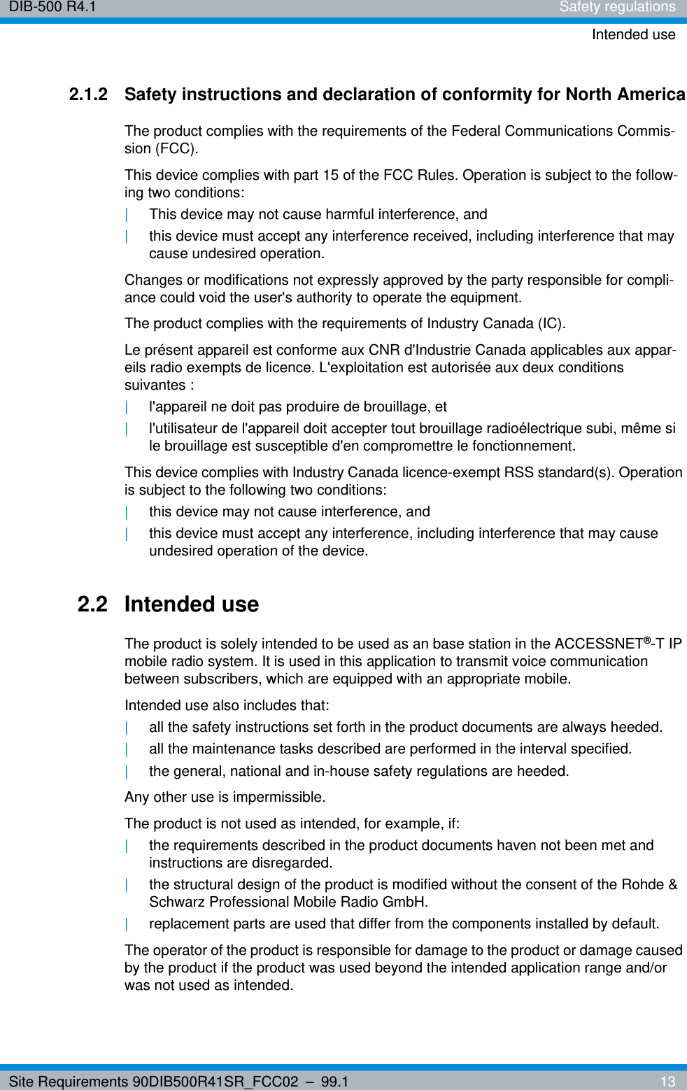
Site Requirements 90DIB500R41SR_FCC02 – 99.1  13DIB-500 R4.1 Safety regulationsIntended use2.1.2 Safety instructions and declaration of conformity for North AmericaThe product complies with the requirements of the Federal Communications Commis-sion (FCC). This device complies with part 15 of the FCC Rules. Operation is subject to the follow-ing two conditions:|This device may not cause harmful interference, and|this device must accept any interference received, including interference that may cause undesired operation.Changes or modifications not expressly approved by the party responsible for compli-ance could void the user's authority to operate the equipment. The product complies with the requirements of Industry Canada (IC).Le présent appareil est conforme aux CNR d'Industrie Canada applicables aux appar-eils radio exempts de licence. L'exploitation est autorisée aux deux conditions suivantes :|l'appareil ne doit pas produire de brouillage, et |l'utilisateur de l'appareil doit accepter tout brouillage radioélectrique subi, même si le brouillage est susceptible d'en compromettre le fonctionnement.This device complies with Industry Canada licence-exempt RSS standard(s). Operation is subject to the following two conditions:|this device may not cause interference, and |this device must accept any interference, including interference that may cause undesired operation of the device.2.2 Intended useThe product is solely intended to be used as an base station in the ACCESSNET®-T IP mobile radio system. It is used in this application to transmit voice communication between subscribers, which are equipped with an appropriate mobile.Intended use also includes that:|all the safety instructions set forth in the product documents are always heeded.|all the maintenance tasks described are performed in the interval specified.|the general, national and in-house safety regulations are heeded.Any other use is impermissible.The product is not used as intended, for example, if:|the requirements described in the product documents haven not been met and instructions are disregarded.|the structural design of the product is modified without the consent of the Rohde & Schwarz Professional Mobile Radio GmbH. |replacement parts are used that differ from the components installed by default.The operator of the product is responsible for damage to the product or damage caused by the product if the product was used beyond the intended application range and/or was not used as intended.
DIB-500 R4.1 Safety regulationsSafety measures14 Site Requirements 90DIB500R41SR_FCC02 – 99.12.3 Safety measuresAll the regulations listed in the following must be adhered to without fail:|If extension cables or multiple socket outlets are used, make sure that they are inspected for proper condition periodically.|After any safety-related parts have been replaced (e.g. power switch or circuit breakers) a safety check must be performed (visual inspection, protective earthing conductor load, leakage resistance, leakage current measurement, function test).|Heed all the other job-specific safety measures and requirements listed in the sequences of actions.Heed the security labelling!In addition to the safety instructions set forth in the product documentation for the , all the safety markings in the equipment rack must be observed. They point out potential hazardous areas and must neither be removed nor changed.2.3.1 Authorised personnelThe product may be transported, set up, connected, commissioned, operated and serv-iced only by specialists who are familiar with and comply with the applicable safety reg-ulations and setup instructions.The specialists must be authorized to perform the required tasks by the person respon-sible for the safety in the enterprise of the operator.Specialists are persons, who:|are trained and experienced in the corresponding field|are familiar with the relevant standards, regulations, provisions and safety codes, and|have been instructed in the mode of operation and the operating conditions of the equipment components|can identify and avert hazardsDepending on the tasks to be performed, the following user groups are distinguished:|operators, who– operate the product.– monitor, interrupt, terminate and restore the operation of the product.|Service personnel: persons, who perform the following additional tasks as com-pared to operators– Set up the product.– Prepare and restore the operational state.– Adjust and/or parameterize the product.– Maintain, look after and repair the product.
Site Requirements 90DIB500R41SR_FCC02 – 99.1  15DIB-500 R4.1 Safety regulationsSafety measures2.3.2 Electromagnetic compatibilityWith specific products, e.g. HF radio equipment, increased electromagnetic radiation may occur as a consequence of operation. Taking into consideration that unborn life is increasingly worthy of being protected, pregnant women should be protected through appropriate measures. People with personal medical devices such as cardiac pacemak-ers and hearing aids can also be endangered by electromagnetic radiation. The opera-tor is obliged to assess workplaces with a considerable risk of exposure to radiation and to avert any hazards.2.3.2.1 Electromagnetic compatibility for EuropeIn proper state and when operated properly, the product complies with all the require-ments in respect of interference radiation according to ETSI EN 301 489-18. The con-nections conducting HF signals must neither be manipulated nor damaged.When using the product with active typical transmitters, the requirements of EN 50385 in respect of the health and safety of a user or any other person in high-frequency fields are met. Compliance with EN 50385 is achieved as of a minimum distance of 1.5 m to the transmitting antenna. A typical transmitter is made up of an omni-directional trans-mitting antenna with an antenna gain of 7.5 dBi installed on a mast with a height of 30 m and connected to the base station through a 40-m cable.2.3.2.2 Electromagnetic compatibility for North AmericaThis equipment has been tested and found to comply with the limits for a Class A digital device, pursuant to part 15 of the FCC Rules. These limits are designed to provide rea-sonable protection against harmful interference when the equipment is operated in a commercial environment. This equipment generates, uses, and can radiate radio fre-quency energy and, if not installed and used in accordance with the instruction manual, may cause harmful interference to radio communications. Operation of this equipment in a residential area is likely to cause harmful interference in which case the user will be required to correct the interference at his own expense.Cet appareil numérique de la classe A est conforme à la norme NMB-003 du Canada.This Class A digital apparatus complies with Canadian ICES-003.For compliance with the electromagnetic radiation and the limit values with regard to the safety of the general population in high-frequency fields, the document "RF Exposure" must always be observed. For the proper operation of the product, the limit values spec-ified in the document "RF Exposure" must always be complied with. For this purpose, site-specific calculations by the network operator may be required.
DIB-500 R4.1 Safety regulationsSafety measures16 Site Requirements 90DIB500R41SR_FCC02 – 99.1
Site Requirements 90DIB500R41SR_FCC02 – 99.1  17DIB-500 R4.1 Product description3 Product descriptionThe Digital Indoor Base Station (DIB-500 R4.1) is used as a base station in ACCESSNET®-T IP networks. The base station is responsible for radio coverage in a defined radio coverage area. For this purpose, up to eight carriers are available depending on the antenna coupling variant. It can thus provide as many as 32 radio channels (four radio channels per carrier) for the communication of the mobile terminal equipment, via which voice and data is/are transmitted in accordance with the TETRA standard (Terrestrial Trunked Radio).In addition, in networks with a distributed switching architecture, the DIB-500 R4.1 can take on the routing function and thus act as a full system controller node. Moreover, fur-ther functions are available; applications, for example, can be connected directly to the ACCESSNET®-T IP by means of an IP connection.The carriers are provided via the transceiver module TETRA Indoor Base Transceiver (TIB) that can accommodate up to two carriers. Two TIB transceiver modules may be incorporated in the equipment rack of the DIB-500 R4.1, thus providing four carriers. From five carriers, a second equipment rack is used, which can also provide up to four carriers.Two TETRA antenna connections and one GPS antenna connection (Global Position-ing System, GPS) are available for connecting antennas. Internally, the antennas are coupled via the antenna coupling system. In the FlexibleTx variant, project-specific external antenna coupling systems can be used for this purpose. For optimum reception properties, antenna diversity is available.Depending on the requirement, the ACS can provide the following antenna connection variants: |Hybrid|Cavity|High Power or |FlexibleTxFor communicating with other base stations and with the IP Node (IPN) network ele-ment, the DIB-500 R4.1 features Ethernet interfaces for linking to the IP transport net-work.If all the connections to the other network constituents break down during operation, the DIB-500 R4.1 ensures radio operation within its own radio cell. If the DIB-500 R4.1 is operated with a separate routing function in networks with a distributed switching archi-tecture, the base station additionally collects call detail records (CDR).
DIB-500 R4.1 Product descriptionAntenna coupling variants18 Site Requirements 90DIB500R41SR_FCC02 – 99.13.1 Antenna coupling variantsThe DIB-500 R4.1 is available with different antenna coupling systems. The selection of the corresponding antenna coupling system depends on the network requirements.The following antenna interfaces are available for different network requirements:|Hybrid variant– Compact design– As many as eight carriers per network element (two equipment racks with four carriers each)– Highly flexible in the frequency selection– flexible frequency change|Cavity variant– As many as eight carriers per network element (two equipment racks with four carriers each)– higher transmitting power than hybrid variant|High-power variant– up to two carriers per network element,– Higher transmitting power than hybrid and cavity variants|FlexibleTx variant– only equipped with Rx path– up to four carriers per network element,– high flexibility due to the use of project-specific antenna coupling systems– site-specific provision by the network operatorAntenna diversity is available for optimal reception properties.Additional InformationFor more information on the technical characteristics and performance features of the different versions, please refer to the Technical data.
Site Requirements 90DIB500R41SR_FCC02 – 99.1  19DIB-500 R4.1 Requirements concerning the operation roomInfrastructure4 Requirements concerning the operation roomThis chapter describes the requirements for the service room that must always be met to ensure proper operation of the product element as intended at all times.4.1 InfrastructureThe following section describes the infrastructure requirements for the site/service room.4.1.1 General requirementsThe following requirements must be met for being able to operate the product as intended:|The operation room must be self-contained to ensure that the system technology is protected at all times (protection against animals, for example).|Unimpeded access to all the service and supply rooms must be possible.– The required access width to the operation room depends on the dimensions and the weight of the equipment rack, refer to section 4.1.3.1 on page 20, and on the condition of the operation room.However, a minimum access width of 800 mm is required. An access width of at least 1,200 mm is recommended for transports involving an angle.– Access doors must feature an inside width of at least 800 mm.– Opening heights (door, window and elevator openings, etc.) are dependent on the free area in front of the access opening and, if necessary, the depth of the respective elevator.– To position the equipment rack using lifting or transport equipment (e.g. lift trucks), appropriate openings may have to be provided in the operation room.|Service and access rooms must be suitable for the expert installation of any required feed lines.Scope of the site requirementsWhen the building or the operation room is/are modified, the equipment rack site must still meet the site requirements.
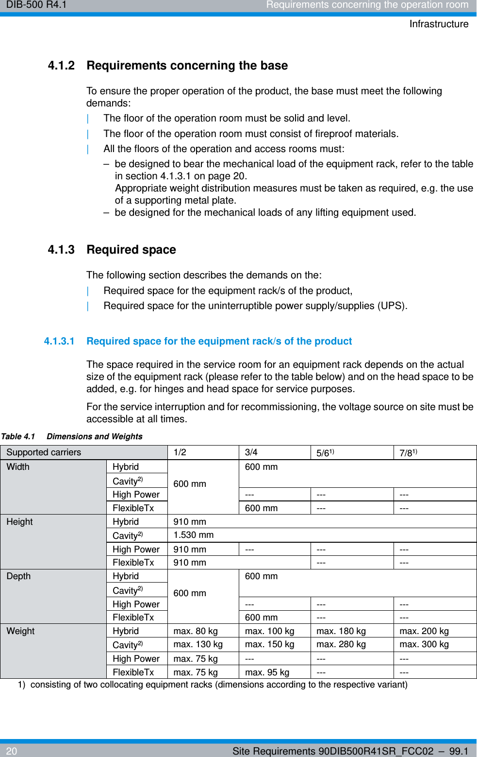
DIB-500 R4.1 Requirements concerning the operation roomInfrastructure20 Site Requirements 90DIB500R41SR_FCC02 – 99.14.1.2 Requirements concerning the baseTo ensure the proper operation of the product, the base must meet the following demands:|The floor of the operation room must be solid and level.|The floor of the operation room must consist of fireproof materials.|All the floors of the operation and access rooms must: – be designed to bear the mechanical load of the equipment rack, refer to the table in section 4.1.3.1 on page 20. Appropriate weight distribution measures must be taken as required, e.g. the use of a supporting metal plate. – be designed for the mechanical loads of any lifting equipment used.4.1.3 Required spaceThe following section describes the demands on the:|Required space for the equipment rack/s of the product,|Required space for the uninterruptible power supply/supplies (UPS).4.1.3.1 Required space for the equipment rack/s of the productThe space required in the service room for an equipment rack depends on the actual size of the equipment rack (please refer to the table below) and on the head space to be added, e.g. for hinges and head space for service purposes.For the service interruption and for recommissioning, the voltage source on site must be accessible at all times.Table 4.1  Dimensions and WeightsSupported carriers 1/2 3/4 5/61)  7/81)Width Hybrid600 mm600 mmCavity2) High Power --- --- ---FlexibleTx 600 mm --- ---Height Hybrid 910 mmCavity2) 1.530 mmHigh Power 910 mm --- --- ---FlexibleTx 910 mm --- ---Depth Hybrid600 mm600 mmCavity2)High Power --- --- ---FlexibleTx 600 mm --- ---Weight Hybrid max. 80 kg max. 100 kg max. 180 kg max. 200 kgCavity2) max. 130 kg max. 150 kg max. 280 kg  max. 300 kgHigh Power max. 75 kg --- --- ---FlexibleTx max. 75 kg max. 95 kg --- ---1)  consisting of two collocating equipment racks (dimensions according to the respective variant)
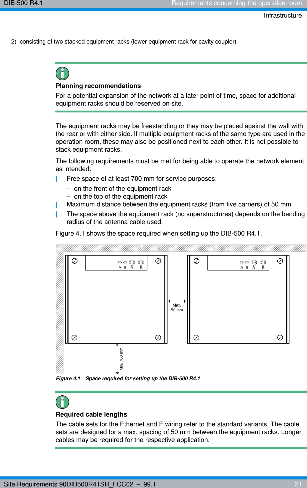
Site Requirements 90DIB500R41SR_FCC02 – 99.1  21DIB-500 R4.1 Requirements concerning the operation roomInfrastructurePlanning recommendationsFor a potential expansion of the network at a later point of time, space for additional equipment racks should be reserved on site.The equipment racks may be freestanding or they may be placed against the wall with the rear or with either side. If multiple equipment racks of the same type are used in the operation room, these may also be positioned next to each other. It is not possible to stack equipment racks.The following requirements must be met for being able to operate the network element as intended:|Free space of at least 700 mm for service purposes:– on the front of the equipment rack– on the top of the equipment rack|Maximum distance between the equipment racks (from five carriers) of 50 mm.|The space above the equipment rack (no superstructures) depends on the bending radius of the antenna cable used.Figure 4.1 shows the space required when setting up the DIB-500 R4.1.Figure 4.1  Space required for setting up the DIB-500 R4.1Required cable lengthsThe cable sets for the Ethernet and E wiring refer to the standard variants. The cable sets are designed for a max. spacing of 50 mm between the equipment racks. Longer cables may be required for the respective application. 2)  consisting of two stacked equipment racks (lower equipment rack for cavity coupler)
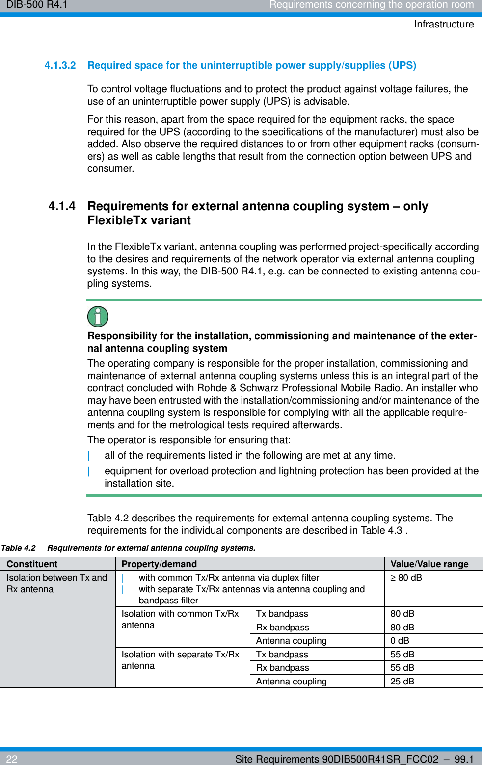
DIB-500 R4.1 Requirements concerning the operation roomInfrastructure22 Site Requirements 90DIB500R41SR_FCC02 – 99.14.1.3.2 Required space for the uninterruptible power supply/supplies (UPS)To control voltage fluctuations and to protect the product against voltage failures, the use of an uninterruptible power supply (UPS) is advisable.For this reason, apart from the space required for the equipment racks, the space required for the UPS (according to the specifications of the manufacturer) must also be added. Also observe the required distances to or from other equipment racks (consum-ers) as well as cable lengths that result from the connection option between UPS and consumer.4.1.4 Requirements for external antenna coupling system – only FlexibleTx variantIn the FlexibleTx variant, antenna coupling was performed project-specifically according to the desires and requirements of the network operator via external antenna coupling systems. In this way, the DIB-500 R4.1, e.g. can be connected to existing antenna cou-pling systems.Responsibility for the installation, commissioning and maintenance of the exter-nal antenna coupling systemThe operating company is responsible for the proper installation, commissioning and maintenance of external antenna coupling systems unless this is an integral part of the contract concluded with Rohde & Schwarz Professional Mobile Radio. An installer who may have been entrusted with the installation/commissioning and/or maintenance of the antenna coupling system is responsible for complying with all the applicable require-ments and for the metrological tests required afterwards.The operator is responsible for ensuring that: |all of the requirements listed in the following are met at any time.|equipment for overload protection and lightning protection has been provided at the installation site.Table 4.2 describes the requirements for external antenna coupling systems. The requirements for the individual components are described in Table 4.3 .Table 4.2  Requirements for external antenna coupling systems.Constituent Property/demand Value/Value rangeIsolation between Tx and Rx antenna|with common Tx/Rx antenna via duplex filter|with separate Tx/Rx antennas via antenna coupling and bandpass filter≥ 80 dBIsolation with common Tx/Rx antennaTx bandpass 80 dBRx bandpass 80 dBAntenna coupling 0 dBIsolation with separate Tx/Rx antennaTx bandpass 55 dBRx bandpass 55 dBAntenna coupling 25 dB
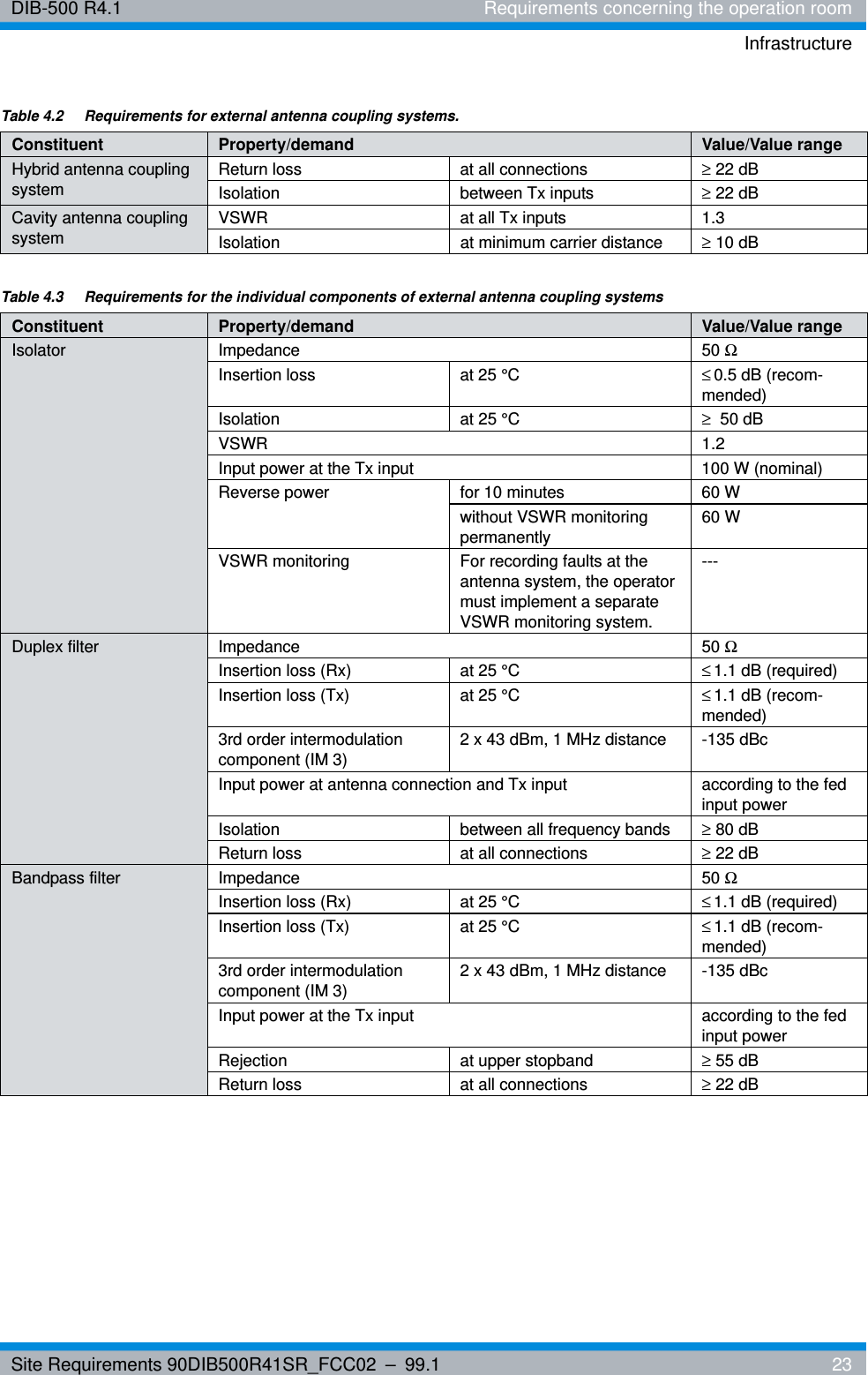
Site Requirements 90DIB500R41SR_FCC02 – 99.1  23DIB-500 R4.1 Requirements concerning the operation roomInfrastructureHybrid antenna coupling systemReturn loss at all connections ≥ 22 dBIsolation between Tx inputs ≥ 22 dBCavity antenna coupling systemVSWR at all Tx inputs 1.3Isolation at minimum carrier distance ≥ 10 dBTable 4.2  Requirements for external antenna coupling systems.Constituent Property/demand Value/Value rangeTable 4.3  Requirements for the individual components of external antenna coupling systemsConstituent Property/demand Value/Value rangeIsolator Impedance 50 ΩInsertion loss at 25 °C ≤0.5 dB (recom-mended)Isolation at 25 °C ≥50 dBVSWR 1.2Input power at the Tx input 100 W (nominal)Reverse power for 10 minutes 60 Wwithout VSWR monitoring permanently60 WVSWR monitoring For recording faults at the antenna system, the operator must implement a separate VSWR monitoring system.---Duplex filter Impedance 50 ΩInsertion loss (Rx) at 25 °C ≤1.1 dB (required)Insertion loss (Tx) at 25 °C ≤1.1 dB (recom-mended)3rd order intermodulation component (IM 3) 2 x 43 dBm, 1 MHz distance -135 dBcInput power at antenna connection and Tx input according to the fed input power Isolation between all frequency bands ≥ 80 dBReturn loss at all connections ≥ 22 dBBandpass filter Impedance 50 ΩInsertion loss (Rx) at 25 °C ≤1.1 dB (required)Insertion loss (Tx) at 25 °C ≤1.1 dB (recom-mended)3rd order intermodulation component (IM 3) 2 x 43 dBm, 1 MHz distance -135 dBcInput power at the Tx input according to the fed input power Rejection at upper stopband ≥ 55 dBReturn loss at all connections ≥ 22 dB
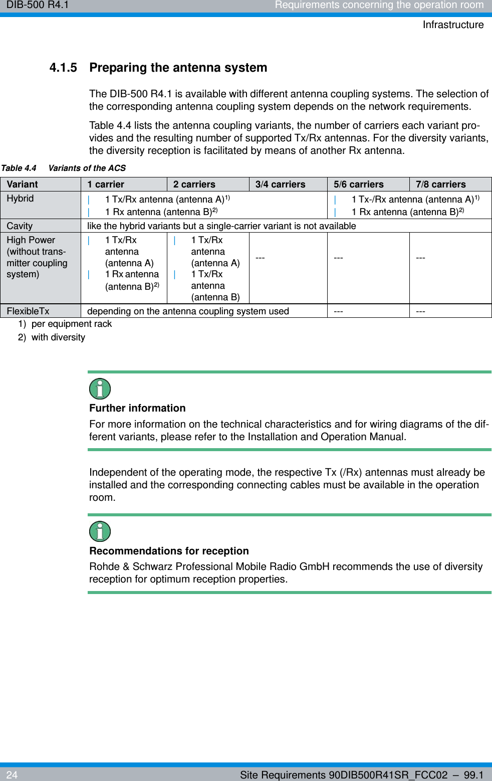
DIB-500 R4.1 Requirements concerning the operation roomInfrastructure24 Site Requirements 90DIB500R41SR_FCC02 – 99.14.1.5 Preparing the antenna systemThe DIB-500 R4.1 is available with different antenna coupling systems. The selection of the corresponding antenna coupling system depends on the network requirements.Table 4.4 lists the antenna coupling variants, the number of carriers each variant pro-vides and the resulting number of supported Tx/Rx antennas. For the diversity variants, the diversity reception is facilitated by means of another Rx antenna.Further informationFor more information on the technical characteristics and for wiring diagrams of the dif-ferent variants, please refer to the Installation and Operation Manual.Independent of the operating mode, the respective Tx (/Rx) antennas must already be installed and the corresponding connecting cables must be available in the operation room. Recommendations for receptionRohde & Schwarz Professional Mobile Radio GmbH recommends the use of diversity reception for optimum reception properties.Table 4.4  Variants of the ACSVariant 1 carrier 2 carriers 3/4 carriers 5/6 carriers 7/8 carriersHybrid |1 Tx/Rx antenna (antenna A)1) |1 Rx antenna (antenna B)2) |1 Tx-/Rx antenna (antenna A)1)|1 Rx antenna (antenna B)2)Cavity like the hybrid variants but a single-carrier variant is not availableHigh Power (without trans-mitter coupling system)|1 Tx/Rx antenna (antenna A)|1 Rx antenna (antenna B)2)|1Tx/Rx antenna (antenna A)|1Tx/Rx antenna (antenna B)--- --- ---FlexibleTx depending on the antenna coupling system used --- ---1)  per equipment rack2)  with diversity
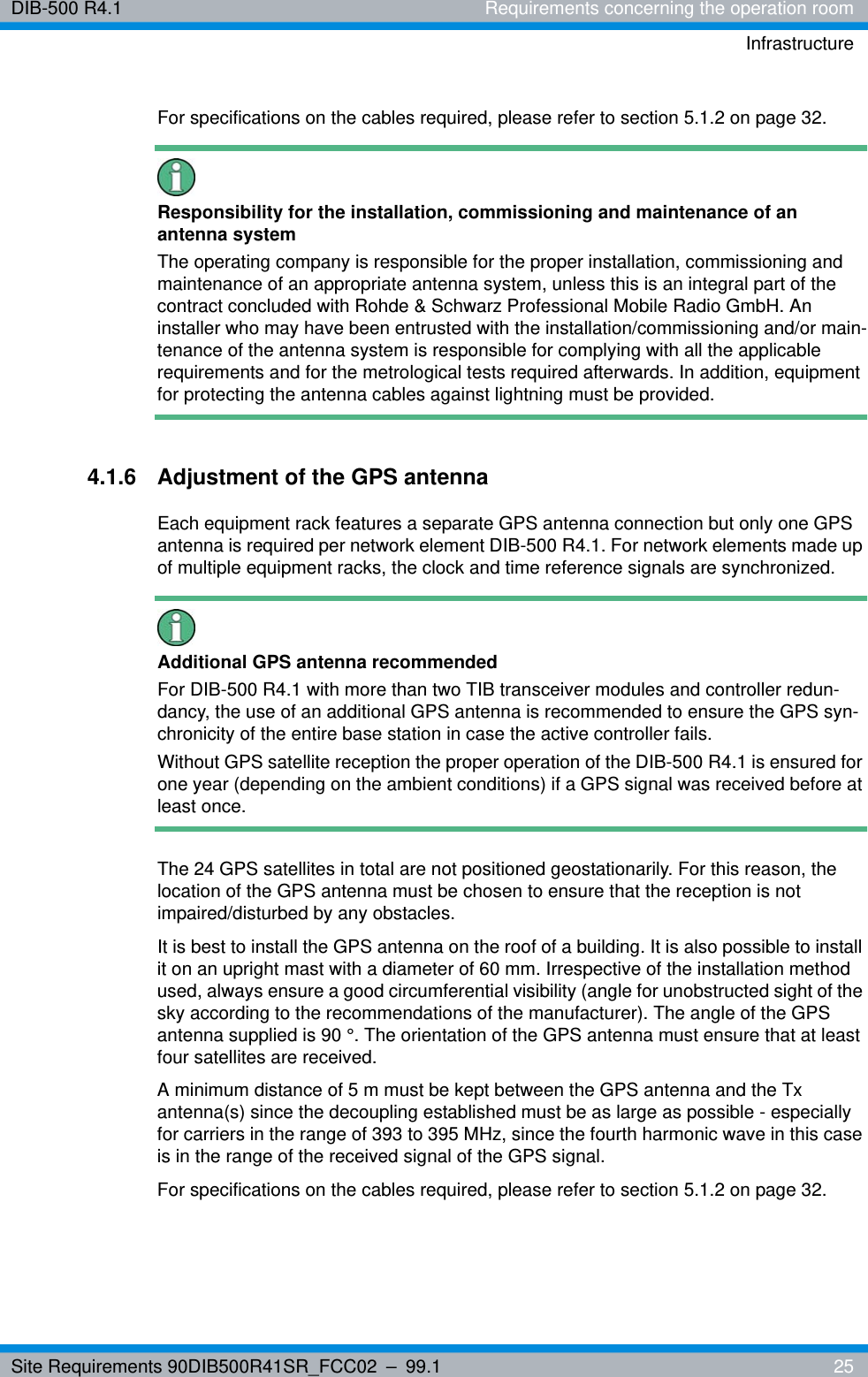
Site Requirements 90DIB500R41SR_FCC02 – 99.1  25DIB-500 R4.1 Requirements concerning the operation roomInfrastructureFor specifications on the cables required, please refer to section 5.1.2 on page 32. Responsibility for the installation, commissioning and maintenance of an antenna systemThe operating company is responsible for the proper installation, commissioning and maintenance of an appropriate antenna system, unless this is an integral part of the contract concluded with Rohde & Schwarz Professional Mobile Radio GmbH. An installer who may have been entrusted with the installation/commissioning and/or main-tenance of the antenna system is responsible for complying with all the applicable requirements and for the metrological tests required afterwards. In addition, equipment for protecting the antenna cables against lightning must be provided.4.1.6 Adjustment of the GPS antennaEach equipment rack features a separate GPS antenna connection but only one GPS antenna is required per network element DIB-500 R4.1. For network elements made up of multiple equipment racks, the clock and time reference signals are synchronized.Additional GPS antenna recommendedFor DIB-500 R4.1 with more than two TIB transceiver modules and controller redun-dancy, the use of an additional GPS antenna is recommended to ensure the GPS syn-chronicity of the entire base station in case the active controller fails.Without GPS satellite reception the proper operation of the DIB-500 R4.1 is ensured for one year (depending on the ambient conditions) if a GPS signal was received before at least once.The 24 GPS satellites in total are not positioned geostationarily. For this reason, the location of the GPS antenna must be chosen to ensure that the reception is not impaired/disturbed by any obstacles. It is best to install the GPS antenna on the roof of a building. It is also possible to install it on an upright mast with a diameter of 60 mm. Irrespective of the installation method used, always ensure a good circumferential visibility (angle for unobstructed sight of the sky according to the recommendations of the manufacturer). The angle of the GPS antenna supplied is 90 °. The orientation of the GPS antenna must ensure that at least four satellites are received.A minimum distance of 5 m must be kept between the GPS antenna and the Tx antenna(s) since the decoupling established must be as large as possible - especially for carriers in the range of 393 to 395 MHz, since the fourth harmonic wave in this case is in the range of the received signal of the GPS signal. For specifications on the cables required, please refer to section 5.1.2 on page 32.
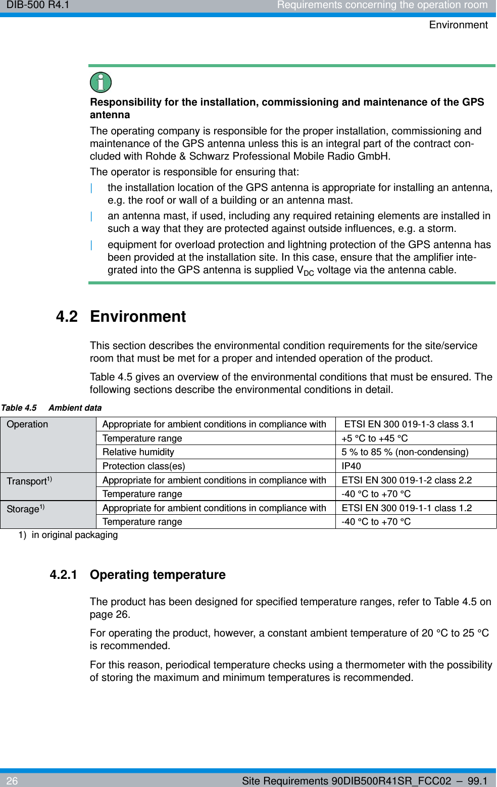
DIB-500 R4.1 Requirements concerning the operation roomEnvironment26 Site Requirements 90DIB500R41SR_FCC02 – 99.1Responsibility for the installation, commissioning and maintenance of the GPS antennaThe operating company is responsible for the proper installation, commissioning and maintenance of the GPS antenna unless this is an integral part of the contract con-cluded with Rohde & Schwarz Professional Mobile Radio GmbH.The operator is responsible for ensuring that: |the installation location of the GPS antenna is appropriate for installing an antenna, e.g. the roof or wall of a building or an antenna mast.|an antenna mast, if used, including any required retaining elements are installed in such a way that they are protected against outside influences, e.g. a storm.|equipment for overload protection and lightning protection of the GPS antenna has been provided at the installation site. In this case, ensure that the amplifier inte-grated into the GPS antenna is supplied VDC voltage via the antenna cable.4.2 EnvironmentThis section describes the environmental condition requirements for the site/service room that must be met for a proper and intended operation of the product.Table 4.5 gives an overview of the environmental conditions that must be ensured. The following sections describe the environmental conditions in detail.4.2.1 Operating temperatureThe product has been designed for specified temperature ranges, refer to Table 4.5 on page 26.For operating the product, however, a constant ambient temperature of 20 °C to 25 °C is recommended.For this reason, periodical temperature checks using a thermometer with the possibility of storing the maximum and minimum temperatures is recommended.Table 4.5  Ambient dataOperation Appropriate for ambient conditions in compliance with  ETSI EN 300 019-1-3 class 3.1Temperature range +5 °C to +45 °CRelative humidity 5 % to 85 % (non-condensing)Protection class(es) IP40Transport1)  Appropriate for ambient conditions in compliance with ETSI EN 300 019-1-2 class 2.2Temperature range -40 °C to +70 °CStorage1) Appropriate for ambient conditions in compliance with ETSI EN 300 019-1-1 class 1.2Temperature range -40 °C to +70 °C1)  in original packaging
Site Requirements 90DIB500R41SR_FCC02 – 99.1  27DIB-500 R4.1 Requirements concerning the operation roomEnvironmentAn air-conditioning system can be used to control the temperature in the operation room. The thermal dissipation loss of the product as well as of other technical equip-ment operated in the operation room must be taken into consideration when controlling the operating temperature. The maximum thermal dissipation loss corresponds to the power consumption, refer to Tabelle 5.5 on page 30.Responsibility of the operatorThe use of an air conditioning system is advisable. The operating company is responsi-ble for the proper installation and the operation of an appropriate air conditioning sys-tem.For information on alternatives to an air conditioning system, please revert to the serv-ice partner responsible for your company.4.2.2 HumidityThe following requirements must be met for being able to operate the product as intended:|The service room must be dry and closed to maintain a constant relative humidity of 50 %, if possible (recommended for slowing down the aging process of integrated components).|Unimpaired air supply to the equipment rack must be ensured.The ventilation concept of the DIB-500 R4.1 provides for the optimum vertical ventila-tion of the incorporated components inside the equipment rack. In this case, the air is drawn in through the perforated equipment rack door and all the dirt and dust particles are filtered out via the ventilator unit. Subsequently, the air is discharged through the top of the perforated equipment rack door.4.2.3 Dust concentrationThe product was developed for use in a municipal industrial area. The average dust concentration per year in a municipal industrial area amounts to a value of up to 200 µg/m³. The dust concentration in the operation room of the product must not exceed this value.Operation rooms that are not completely closed require an appropriate housing.To ensure a minor dust concentration, the use of an overpressure system for the opera-tion room is advisable.Responsibility of the operating companyThe use of an overpressure system is advisable. The operating company is responsible for the proper installation and the operation of an appropriate overpressure system.
DIB-500 R4.1 Requirements concerning the operation roomGrounding and overvoltage protection28 Site Requirements 90DIB500R41SR_FCC02 – 99.1The applicable standards and guidelines for the ambient conditions of the product are set forth in Table 4.5 on page 26.4.3 Grounding and overvoltage protectionThe following chapter describes the requirements for the grounding and overvoltage protection of the site/operation room to ensure that the product can always be used as intended.The applicable national regulations / the applicable regulations of the respective country of use shall apply for the grounding and the overvoltage protection.The cross-section of the earthing conductor must be at least 6 mm2. These earthing conductors must comply with the requirements of DIN VDE 0100 Part 540 (IEC 60364-5-54). According to DIN EN 62305-1 (VDE 0185-305-1), potential equalisation must be installed between the lightning protection system and the electrical system.Standards and GuidelinesPossible as the case may be required measures for the installation of earthing and bonding appliances of telecommunications equipment can be found in ETSI EN 300 253 V2.1.1.4.3.1 Overvoltage protection of the equipment rack (VAC/VDC) Each equipment rack (apart from the equipment rack(s) of the cavity variant) of the DIB-500 R4.1 features a connection panel, via which the integrated components are supplied with voltage and grounded.The protective ground connection of the voltage supply connector of the equipment rack is not a sufficient protection of the system against pulse voltages, such as those that occur during a thunderstorm.For this reason, the equipment rack must be protected against overvoltages at the installation site through appropriate grounding equipment to prevent damage to the sys-tem technology.Responsibility for the installation, commissioning and maintenance of a ground-ing and overvoltage systemThe operating company is responsible for the proper installation, commissioning and maintenance of an appropriate grounding and overvoltage system, unless this is an integral part of the contract concluded with Rohde & Schwarz Professional Mobile Radio GmbH. It is advisable to obtain the opinion of an expert and to implement the safety measures accordingly.
Site Requirements 90DIB500R41SR_FCC02 – 99.1  29DIB-500 R4.1 Requirements concerning the operation roomGrounding and overvoltage protectionTo protect the GPS antenna input against overvoltage (caused by lightning, for exam-ple), a GPS protector is optionally available that should be used in combination with a lightning surge protector to provide for optimum overvoltage protection. The GPS pro-tector can be ordered separately.GPS overvoltage conceptWhen using the GPS protector, the GPS supply lines at the entry into the building should be safeguarded against high overvoltages by a grounded lightning surge protec-tor.Table 4.6 lists the requirements for the lightning surge protector.It must also be ensured that all interfaces of the product are secured against transient overvoltages. These short-term inductive, capacitive or static overvoltages of a few mil-liseconds occur, e.g. because of adjacent interference sources, and can interfere with voltage supply and signal feed lines.Standards and GuidelinesFor information on potential or required measures for installing safety equipment against transient overvoltages for the VDC voltage supply, please refer to the standard ETSI TR 100 283.The required measures for installing safety equipment against transient overvoltages for the VAC voltage supply are described in section 4.3.2 on page 29.4.3.2 Overvoltage protection of the voltage supply (VAC)For VAC voltage supply systems, ensure that the voltage source on site meets the fol-lowing demands:|The voltage supply circuit of the voltage source must not exceed 275 VAC. |The voltage source must be connected to a grounding system. The voltage between the grounding connector and earth must not exceed 275 VAC.|Appropriate safety measures must be taken to protect the voltage supply circuit of the voltage source against overvoltages.|A sub-distribution system including a fuse must be available for each equipment rack in the voltage supply circuit of the voltage source.Table 4.6  Requirements for the lightning surge protectorProperty Requirement/ValueOvervoltage discharger Gas discharge tube1) 1)  Depending on the manufacturer, the gas discharge tubes may have to be ordered se-parately and integrated into the overvoltage discharger.Trigger voltage 90 V
DIB-500 R4.1 Requirements concerning the operation roomGrounding and overvoltage protection30 Site Requirements 90DIB500R41SR_FCC02 – 99.1Standards and DirectivesPossible and required measures for installing safety means as a protection against overvoltages can be found in the standard DIN VDE 0100 Part 540 (IEC 60364-5-54).Responsibility for the installation, commissioning and maintenance of a ground-ing and overvoltage systemThe operating company is responsible for the proper installation, commissioning and maintenance of an appropriate grounding and overvoltage system, unless this is an integral part of the contract concluded with Rohde & Schwarz Professional Mobile Radio GmbH. It is advisable to obtain the opinion of an expert and to implement the safety measures accordingly.4.3.3 Overvoltage protection of the supply linesAll the supply cables (HF/AF and data supply cables) must be grounded and fused.The following requirements must be met for being able to operate the product as intended:|All the RF feed lines must be grounded appropriately.|The GPS supply line(s) must be protected by means of appropriate overvoltage pro-tection elements, refer to section 4.3.1 on page 28.|All the AF and data supply cables must be protected through appropriate overvolt-age protection elements.Responsibility for implementing overvoltage protection measuresThe responsibility for the proper execution of the overvoltage protection measures is determined project-specifically as required.
Site Requirements 90DIB500R41SR_FCC02 – 99.1  31DIB-500 R4.1 Requirements concerning the electrical systemCable requirements and cable specifications5 Requirements concerning the electrical sys-temThis chapter describes the requirements for the electric system that must be met to ensure proper operation of the product as intended at all times.5.1 Cable requirements and cable specificationsThe following sections describe general cable requirements and cable specifications for data and HF cables that must be met for the proper operation of the product at the installation location.5.1.1 General cable requirementsAll the feed lines must be identified or labelled according to their functions, e. g. the grounding cable with "grounding + the name of the network element".All the feed lines must be routed or suspended so that:|Operation of the device is not impaired|Tripping hazards for operators are safely prevented|The required minimum distances are maintained, see section 4.1 on page 19,|The manufacturer's specification/information for the cables and connectors used are followed. If necessary, contact the respective manufacturer to obtain this infor-mation.Excess cable lengths requiredThe excess cable lengths required are derived from the corresponding termination points inside the equipment rack and from the position of the equipment cabinet in the operation room. The cables must not be subject to any tensile stress whenever the equipment cabinet has to be moved for service work (refer to section 4.1.3 as of page 20). An excess cable length of at least 1.5 m is recommended.
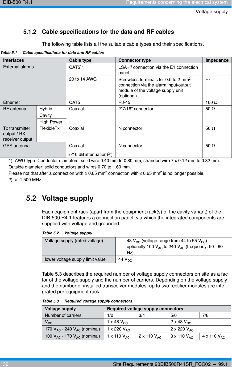
DIB-500 R4.1 Requirements concerning the electrical systemVoltage supply32 Site Requirements 90DIB500R41SR_FCC02 – 99.15.1.2 Cable specifications for the data and RF cablesThe following table lists all the suitable cable types and their specifications.5.2 Voltage supplyEach equipment rack (apart from the equipment rack(s) of the cavity variant) of the DIB-500 R4.1 features a connection panel, via which the integrated components are supplied with voltage and grounded.Table 5.3 describes the required number of voltage supply connectors on site as a fac-tor of the voltage supply and the number of carriers. Depending on the voltage supply and the number of installed transceiver modules, up to two rectifier modules are inte-grated per equipment rack.Table 5.1  Cable specifications for data and RF cablesInterfaces Cable type Connector type ImpedanceExternal alarms CAT51)  LSA+1) connection via the E1 connection panel---20 to 14 AWG Screwless terminals for 0.5 to 2-mm2 – connection via the alarm input/output module of the voltage supply unit (optional)---Ethernet CAT5 RJ-45 100 ΩRF antenna Hybrid Coaxial 2*7/16" connector 50 ΩCavityHigh PowerTx transmitter output / RX receiver outputFlexibleTx Coaxial N connector 50 ΩGPS antenna Coaxial(≤10 dB attenuation)2) )N connector 50 Ω1)  AWG type: Conductor diameters: solid wire 0.40 mm to 0.80 mm, stranded wire 7 x 0.12 mm to 0.32 mm.Outside diameter: solid conductors and wires 0.70 to 1.60 mm.Please not that after a connection with ≥ 0.65 mm2 connection with ≤0.65 mm2 is no longer possible.2)  at 1,500 MHzTable 5.2  Voltage supplyVoltage supply (rated voltage) |48 VDC (voltage range from 44 to 55 VDC)|optionally 100 VAC to 240 VAC (frequency: 50 - 60 Hz)lower voltage supply limit value 44 VDCTable 5.3  Required voltage supply connectorsVoltage supply Required voltage supply connectorsNumber of carriers 1/2 3/4  5/6 7/8VDC 1 x 48 VDC 2 x 48 VDC170 VAC - 240 VAC (nominal) 1 x 220 VAC 2 x 220 VAC100 VAC - 170 VAC (nominal) 1 x 110 VAC 2 x 110 VAC 3 x 110 VAC 4 x 110 VAC
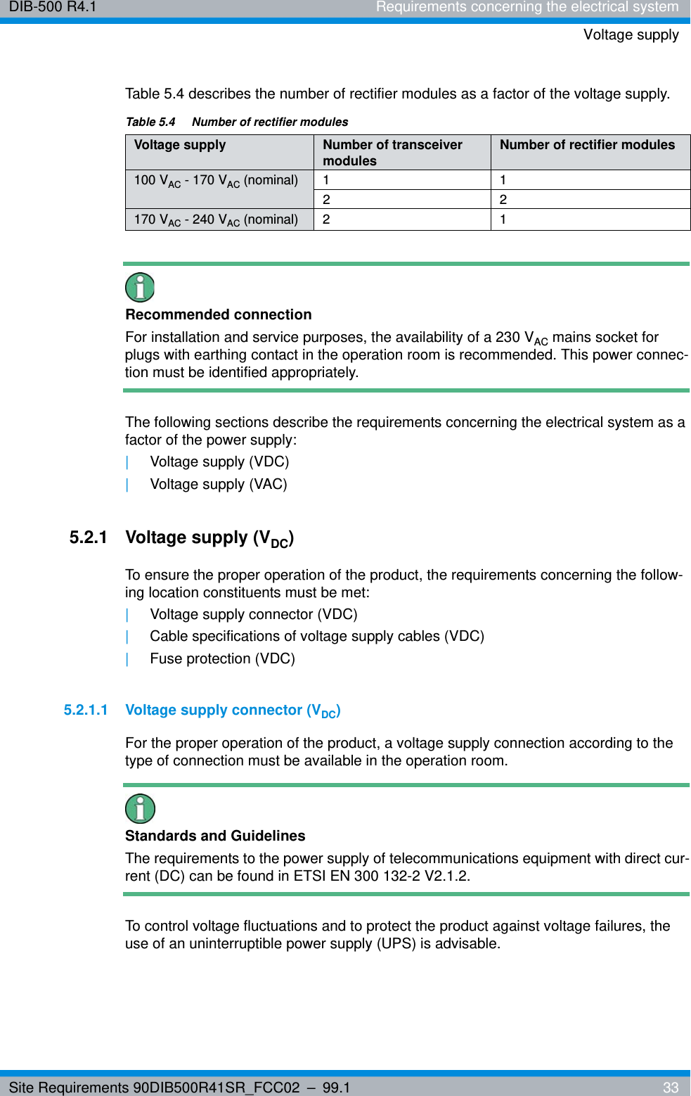
Site Requirements 90DIB500R41SR_FCC02 – 99.1  33DIB-500 R4.1 Requirements concerning the electrical systemVoltage supplyTable 5.4 describes the number of rectifier modules as a factor of the voltage supply.Recommended connectionFor installation and service purposes, the availability of a 230 VAC mains socket for plugs with earthing contact in the operation room is recommended. This power connec-tion must be identified appropriately.The following sections describe the requirements concerning the electrical system as a factor of the power supply:|Voltage supply (VDC)|Voltage supply (VAC)5.2.1 Voltage supply (VDC)To ensure the proper operation of the product, the requirements concerning the follow-ing location constituents must be met:|Voltage supply connector (VDC)|Cable specifications of voltage supply cables (VDC)|Fuse protection (VDC)5.2.1.1 Voltage supply connector (VDC)For the proper operation of the product, a voltage supply connection according to the type of connection must be available in the operation room.Standards and GuidelinesThe requirements to the power supply of telecommunications equipment with direct cur-rent (DC) can be found in ETSI EN 300 132-2 V2.1.2.To control voltage fluctuations and to protect the product against voltage failures, the use of an uninterruptible power supply (UPS) is advisable.Table 5.4  Number of rectifier modulesVoltage supply Number of transceiver modulesNumber of rectifier modules100 VAC - 170 VAC (nominal) 1 122170 VAC - 240 VAC (nominal) 2 1
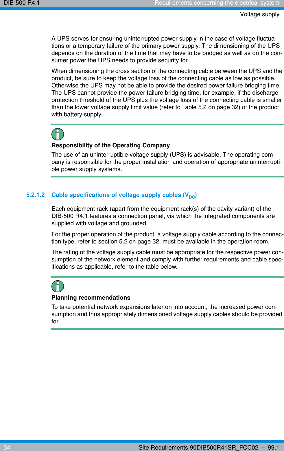
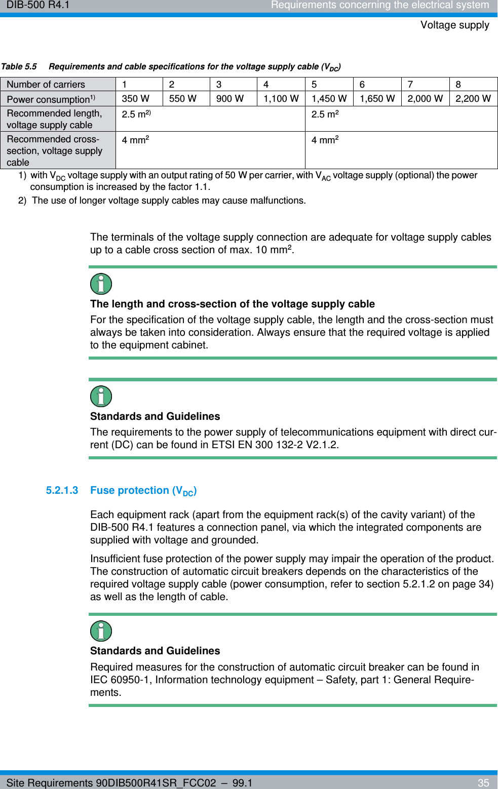
DIB-500 R4.1 Requirements concerning the electrical systemVoltage supply34 Site Requirements 90DIB500R41SR_FCC02 – 99.1A UPS serves for ensuring uninterrupted power supply in the case of voltage fluctua-tions or a temporary failure of the primary power supply. The dimensioning of the UPS depends on the duration of the time that may have to be bridged as well as on the con-sumer power the UPS needs to provide security for.When dimensioning the cross section of the connecting cable between the UPS and the product, be sure to keep the voltage loss of the connecting cable as low as possible. Otherwise the UPS may not be able to provide the desired power failure bridging time. The UPS cannot provide the power failure bridging time, for example, if the discharge protection threshold of the UPS plus the voltage loss of the connecting cable is smaller than the lower voltage supply limit value (refer to Table 5.2 on page 32) of the product with battery supply.Responsibility of the Operating CompanyThe use of an uninterruptible voltage supply (UPS) is advisable. The operating com-pany is responsible for the proper installation and operation of appropriate uninterrupti-ble power supply systems.5.2.1.2 Cable specifications of voltage supply cables (VDC)Each equipment rack (apart from the equipment rack(s) of the cavity variant) of the DIB-500 R4.1 features a connection panel, via which the integrated components are supplied with voltage and grounded.For the proper operation of the product, a voltage supply cable according to the connec-tion type, refer to section 5.2 on page 32, must be available in the operation room.The rating of the voltage supply cable must be appropriate for the respective power con-sumption of the network element and comply with further requirements and cable spec-ifications as applicable, refer to the table below.Planning recommendationsTo take potential network expansions later on into account, the increased power con-sumption and thus appropriately dimensioned voltage supply cables should be provided for.
Site Requirements 90DIB500R41SR_FCC02 – 99.1  35DIB-500 R4.1 Requirements concerning the electrical systemVoltage supplyThe terminals of the voltage supply connection are adequate for voltage supply cables up to a cable cross section of max. 10 mm2.The length and cross-section of the voltage supply cableFor the specification of the voltage supply cable, the length and the cross-section must always be taken into consideration. Always ensure that the required voltage is applied to the equipment cabinet.Standards and GuidelinesThe requirements to the power supply of telecommunications equipment with direct cur-rent (DC) can be found in ETSI EN 300 132-2 V2.1.2.5.2.1.3 Fuse protection (VDC)Each equipment rack (apart from the equipment rack(s) of the cavity variant) of the DIB-500 R4.1 features a connection panel, via which the integrated components are supplied with voltage and grounded.Insufficient fuse protection of the power supply may impair the operation of the product. The construction of automatic circuit breakers depends on the characteristics of the required voltage supply cable (power consumption, refer to section 5.2.1.2 on page 34) as well as the length of cable.Standards and GuidelinesRequired measures for the construction of automatic circuit breaker can be found in IEC 60950-1, Information technology equipment – Safety, part 1: General Require-ments.Table 5.5  Requirements and cable specifications for the voltage supply cable (VDC)Number of carriers12345678Power consumption1)  350 W 550 W 900 W 1,100 W 1,450 W 1,650 W 2,000 W 2,200 WRecommended length, voltage supply cable2.5 m2)  2.5 m2Recommended cross-section, voltage supply cable4mm24mm21)  with VDC voltage supply with an output rating of 50 W per carrier, with VAC voltage supply (optional) the power consumption is increased by the factor 1.1.2)  The use of longer voltage supply cables may cause malfunctions.
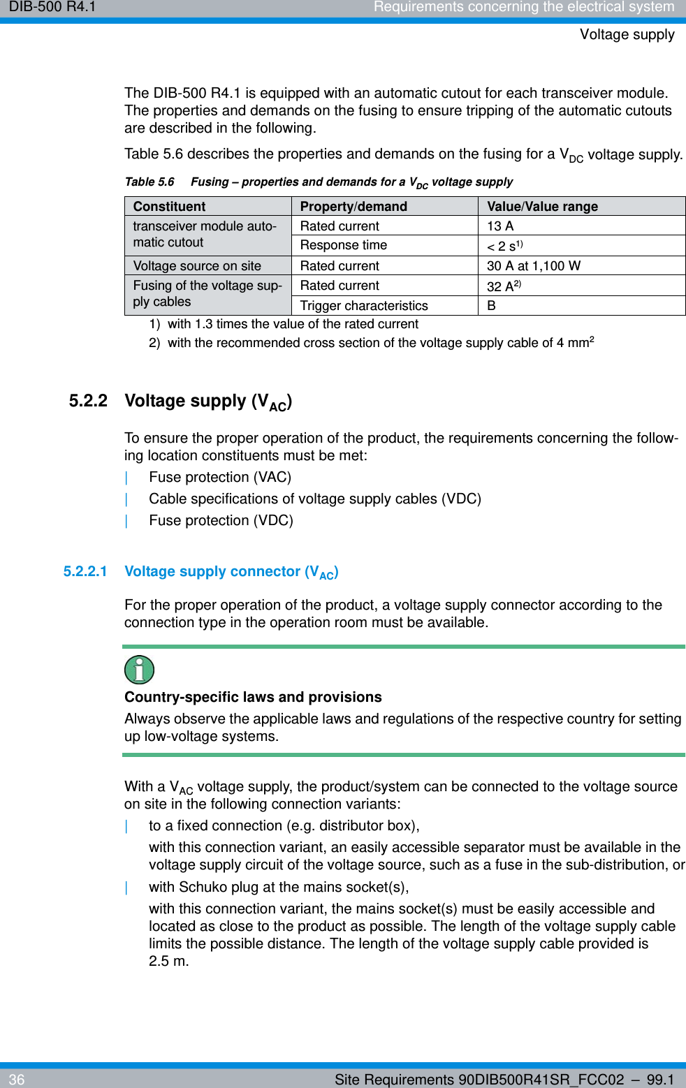
DIB-500 R4.1 Requirements concerning the electrical systemVoltage supply36 Site Requirements 90DIB500R41SR_FCC02 – 99.1The DIB-500 R4.1 is equipped with an automatic cutout for each transceiver module. The properties and demands on the fusing to ensure tripping of the automatic cutouts are described in the following. Table 5.6 describes the properties and demands on the fusing for a VDC voltage supply.5.2.2 Voltage supply (VAC)To ensure the proper operation of the product, the requirements concerning the follow-ing location constituents must be met:|Fuse protection (VAC)|Cable specifications of voltage supply cables (VDC)|Fuse protection (VDC)5.2.2.1 Voltage supply connector (VAC)For the proper operation of the product, a voltage supply connector according to the connection type in the operation room must be available.Country-specific laws and provisionsAlways observe the applicable laws and regulations of the respective country for setting up low-voltage systems. With a VAC voltage supply, the product/system can be connected to the voltage source on site in the following connection variants: |to a fixed connection (e.g. distributor box),with this connection variant, an easily accessible separator must be available in the voltage supply circuit of the voltage source, such as a fuse in the sub-distribution, or|with Schuko plug at the mains socket(s),with this connection variant, the mains socket(s) must be easily accessible and located as close to the product as possible. The length of the voltage supply cable limits the possible distance. The length of the voltage supply cable provided is 2.5 m.Table 5.6  Fusing – properties and demands for a VDC voltage supplyConstituent Property/demand Value/Value rangetransceiver module auto-matic cutoutRated current 13 AResponse time < 2 s1) 1)  with 1.3 times the value of the rated currentVoltage source on site Rated current 30 A at 1,100 WFusing of the voltage sup-ply cablesRated current 32 A2) 2)  with the recommended cross section of the voltage supply cable of 4 mm2Trigger characteristics B
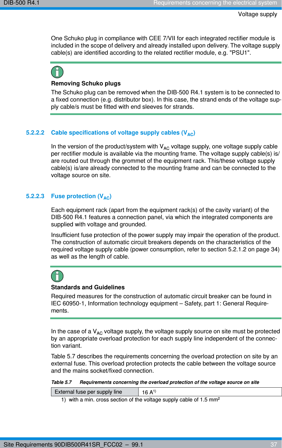
Site Requirements 90DIB500R41SR_FCC02 – 99.1  37DIB-500 R4.1 Requirements concerning the electrical systemVoltage supplyOne Schuko plug in compliance with CEE 7/VII for each integrated rectifier module is included in the scope of delivery and already installed upon delivery. The voltage supply cable(s) are identified according to the related rectifier module, e.g. "PSU1".Removing Schuko plugsThe Schuko plug can be removed when the DIB-500 R4.1 system is to be connected to a fixed connection (e.g. distributor box). In this case, the strand ends of the voltage sup-ply cable/s must be fitted with end sleeves for strands.5.2.2.2 Cable specifications of voltage supply cables (VAC)In the version of the product/system with VAC voltage supply, one voltage supply cable per rectifier module is available via the mounting frame. The voltage supply cable(s) is/are routed out through the grommet of the equipment rack. This/these voltage supply cable(s) is/are already connected to the mounting frame and can be connected to the voltage source on site.5.2.2.3 Fuse protection (VAC)Each equipment rack (apart from the equipment rack(s) of the cavity variant) of the DIB-500 R4.1 features a connection panel, via which the integrated components are supplied with voltage and grounded.Insufficient fuse protection of the power supply may impair the operation of the product. The construction of automatic circuit breakers depends on the characteristics of the required voltage supply cable (power consumption, refer to section 5.2.1.2 on page 34) as well as the length of cable.Standards and GuidelinesRequired measures for the construction of automatic circuit breaker can be found in IEC 60950-1, Information technology equipment – Safety, part 1: General Require-ments.In the case of a VAC voltage supply, the voltage supply source on site must be protected by an appropriate overload protection for each supply line independent of the connec-tion variant.Table 5.7 describes the requirements concerning the overload protection on site by an external fuse. This overload protection protects the cable between the voltage source and the mains socket/fixed connection.Table 5.7   Requirements concerning the overload protection of the voltage source on siteExternal fuse per supply line 16 A1) 1)  with a min. cross section of the voltage supply cable of 1.5 mm2
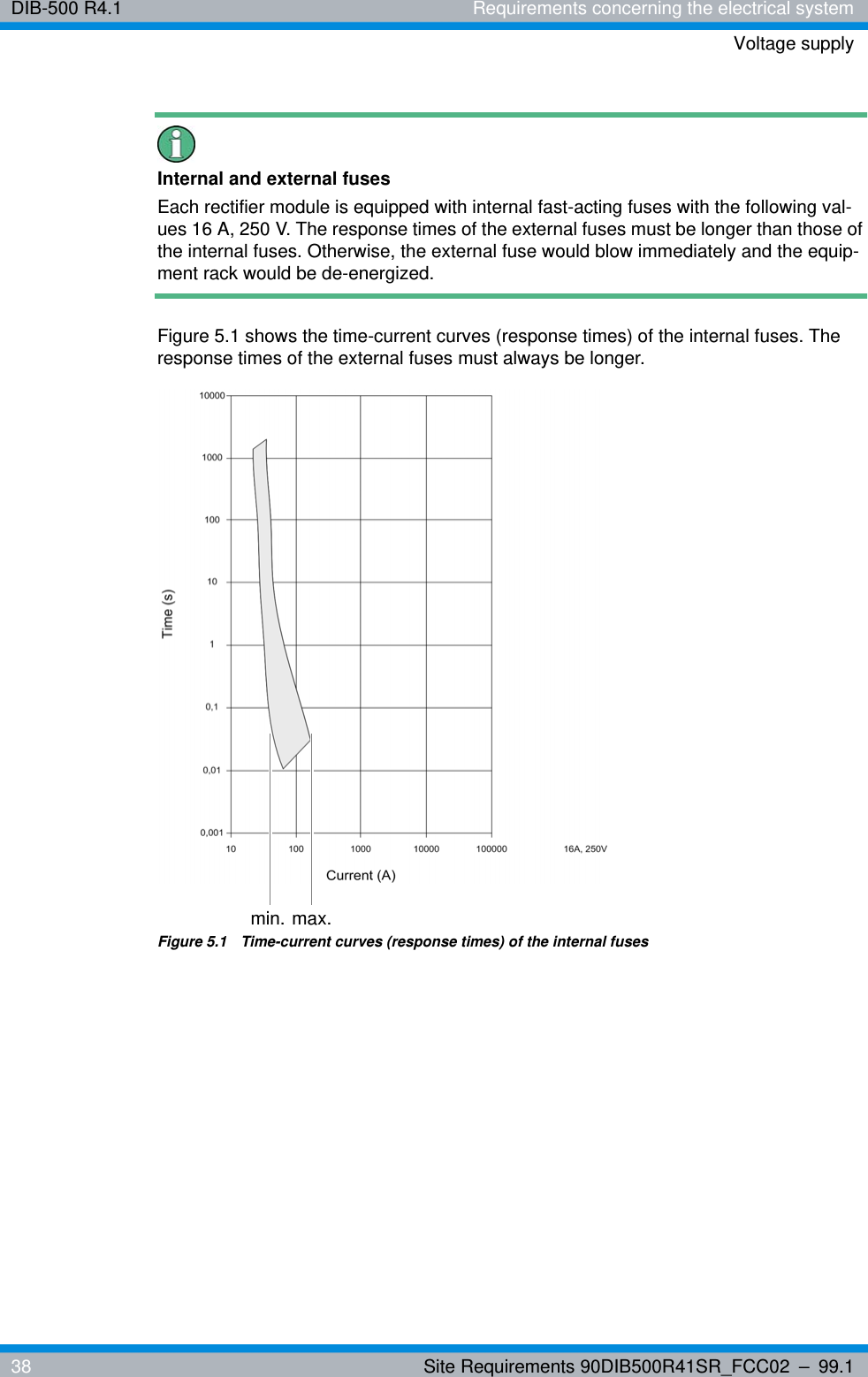
DIB-500 R4.1 Requirements concerning the electrical systemVoltage supply38 Site Requirements 90DIB500R41SR_FCC02 – 99.1Internal and external fusesEach rectifier module is equipped with internal fast-acting fuses with the following val-ues 16 A, 250 V. The response times of the external fuses must be longer than those of the internal fuses. Otherwise, the external fuse would blow immediately and the equip-ment rack would be de-energized.Figure 5.1 shows the time-current curves (response times) of the internal fuses. The response times of the external fuses must always be longer.Figure 5.1  Time-current curves (response times) of the internal fusesmax.min.
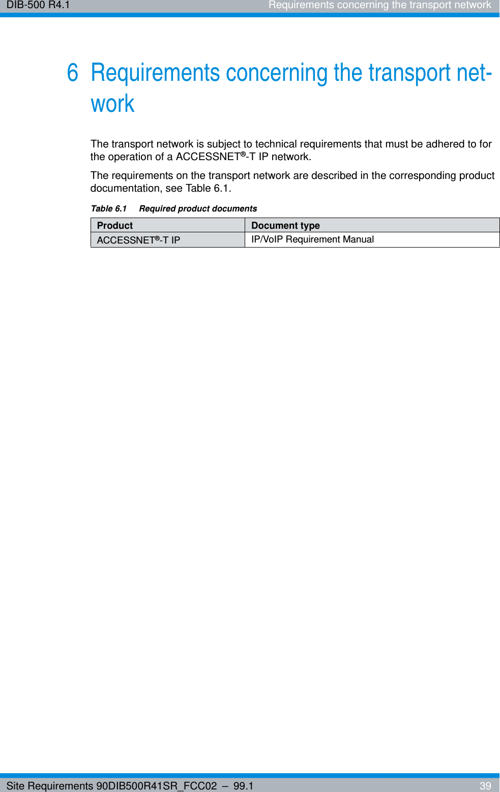
Site Requirements 90DIB500R41SR_FCC02 – 99.1  39DIB-500 R4.1 Requirements concerning the transport network6 Requirements concerning the transport net-workThe transport network is subject to technical requirements that must be adhered to for the operation of a ACCESSNET®-T IP network.The requirements on the transport network are described in the corresponding product documentation, see Table 6.1.Table 6.1  Required product documentsProduct Document typeACCESSNET®-T IP IP/VoIP Requirement Manual
DIB-500 R4.1 Requirements concerning the transport network40 Site Requirements 90DIB500R41SR_FCC02 – 99.1

Navigation menu