Hytrol Conveyor Prosort 100 Users Manual MixMex
2015-02-09
: Hytrol-Conveyor Hytrol-Conveyor-Prosort-100-Users-Manual-566354 hytrol-conveyor-prosort-100-users-manual-566354 hytrol-conveyor pdf
Open the PDF directly: View PDF ![]() .
.
Page Count: 43
Installation
and
Maintenance
Manual
with Safety Information
and Parts List
RECOMMENDED SPARE PARTS HIGHLIGHTED IN GRAY
IMPORTANT!
DO NOT DESTROY
Model ProSort 100
HYTROL CONVEYOR CO., INC.
© COPYRIGHT 2000–HYTROL CONVEYOR CO., INC.
Jonesboro, Arkansas
Manteca, California
Effective August, 2000
Bulletin # 471
IMPORTANTE!
NO DESTRUIR
Manual
de Instalación
y
Mantenimiento
con Información sobre Seguridad
y Lista de Partes
LAS PARTES DE REPUESTO RECOMENDADAS SE RESALTAN EN GRIS

2
●Table of Contents ●
Tabla de Contenido
Warning Signs . . . . . . . . . . . . . . . . . . . .3
INTRODUCTION
Receiving and Uncrating . . . . . . . . . . . .4
INSTALLATION
Installation Safety Precautions . . . . . . . .5
Location . . . . . . . . . . . . . . . . . . . . . . . .6
Conveyor Set-Up . . . . . . . . . . . . . . . . . .7
Electrical Equipment . . . . . . . . . . . . . .10
OPERATION
Operation Safety Precautions . . . . . . .12
Conveyor Start-Up . . . . . . . . . . . . . . . .12
MAINTENANCE
Maintenance Safety Precautions . . . . .13
Lubrication . . . . . . . . . . . . . . . . . . . . .13
Controllling the ProSort . . . . . . . . . . . .14
Drive Switch Checklist . . . . . . . . . . . . .20
Carrying Chain Installation . . . . . . . . .22
Locating the Spur . . . . . . . . . . . . . . . .24
Divert Switch Removal Procedure . . . .25
Trouble Shooting . . . . . . . . . . . . . . . . .26
Preventive Maintenance Checklist . . . .28
Preventive Maintenance Details . . . . . .30
How To Order Replacement Parts . . . .31
ProSort 131 Parts Drawing . . . . . . . . .32
ProSort 131 Parts List . . . . . . . . . . . . .36
Divert Switch Parts Drawing . . . . . . . .38
Divert Switch Parts List . . . . . . . . . . . .39
Safety Switch Assembly . . . . . . . . . . . .40
Señales de Advertencia . . . . . . . . . . . . .3
INTRODUCCION
Recepción y Desembalaje . . . . . . . . . . .4
INSTALACION
Seguridad en la Instalación . . . . . . . . . .5
Localización . . . . . . . . . . . . . . . . . . . . .6
Montaje . . . . . . . . . . . . . . . . . . . . . . . . .7
Equipo Eléctrico . . . . . . . . . . . . . . . . .10
OPERACION
Seguridad en la Operación . . . . . . . . .12
Arranque del Transportador . . . . . . . . .12
MANTENIMIENTO
Seguridad en el Mantenimiento . . . . . .13
Lubricación . . . . . . . . . . . . . . . . . . . . .13
Controlando el ProSort . . . . . . . . . . . .14
Revisión del Interruptor . . . . . . . . . . . .20
Instalación de Cadenas . . . . . . . . . . .22
Colocando las Espuelas . . . . . . . . . . .24
Remoción del Interruptor Desviador . . .25
Resolviendo Problemas . . . . . . . . . . . .27
Lista de Mantenimiento Preventivo . . .29
Detalles de Mantemiento . . . . . . . . . . .30
Como Ordenar Partes de Repuesto . . .31
Dibujo de Partes del ProSort 131 . . . . .32
Lista de Partes del ProSort 131 . . . . . .36
Dibujo del Interruptor Desviador . . . . . .38
Partes del Interruptor Desviador . . . . .39
Interruptor de Seguridad . . . . . . . . . . .40
3
In an effort to reduce the possibility of injury to personnel
working around HYTROL conveying equipment, warning
signs are placed at various points on the equipment to alert
them of potential dangers. Please check equipment and
note all warning signs. Make certain your personnel are
alerted to and obey these warnings. Shown below are typ-
ical signs that are attached to this equipment.
En un esfuerzo por reducir la posibilidad de accidentes del
personal trabajando junto al equipo de transportación
HYTROL, se colocan señales de advertencia en diferentes
puntos del equipo para alertarlos de riesgos potenciales.
Por favor verifique el equipo y asegúrese de ver todas las
señales de advertencia. Asegúrese de que su personal esté
alerta y obedezca las señales. Abajo se muestran las
señales que se encuentran en este equipo.
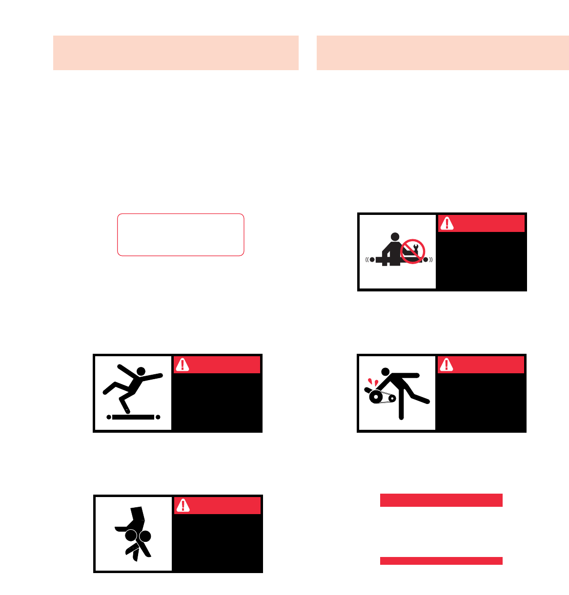
● Warning Signs ●
Señales de Advertencia
PLACED ON ALL POWERED
CONVEYORS NEAR DRIVE
AND/OR CONTROLS.
PLACED NEXT TO DRIVE, BOTH
SIDES.
PLACED ON 20 FT.
INTERVALS,BOTH SIDES.
PLACED AT DRIVE OF ALL
POWERED CONVEYORS.
PLACED ON TERMINATING ENDS.
COLOCADAS EN TODOS LOS
TRANSPORTADORES
MOTORIZADOS CERCA AL
MOTOR Y/O LOS CONTROLES
COLOCADAS EN LA UNIDAD
MOTRIZ DE TODOS LOS TRANS-
PORTADORES MOTORIZADOS.
COLOCADAS EN INTERVALOS DE
20 PIES, A AMBOS LADOS.
COLOCADAS EN LOS EXTREMOS.
COLOCADAS JUNTO A LA UNIDAD
MOTRIZ, EN AMBOS LADOS.
DANGER
KEEP OFF
Climbing, sitting,
walking or riding on
conveyor at any time
will cause severe
injury or death
WARNING
LOCK OUT POWER
before removing
guard
Exposed moving
parts can cause
severe injury
WARNING
LOCK OUT POWER
before removing guard
Servicing moving or
energized equipment
can cause severe injury
WARNING
KEEP AWAY
Moving equipment
can cause severe
injury
WARNING!
DO NOT START CONVEYOR
UNTIL PERSONNEL ARE CLEAR
WARNING
DO NOT REMOVE THIS SIGN FROM THIS MACHINE
NEVER... START CONVEYOR UNTIL PERSONNEL ARE CLEAR
NEVER... LUBRICATE OR REPAIR WHILE CONVEYOR IS RUNNING
NEVER... RUN THE CONVEYOR WITH GUARDS REMOVED
NEVER...
NEVER... ALLOW ANY PART OF YOUR BODY TO COME IN CONTACT
WITH THE CONVEYOR PULLEYS WHILE IT IS RUNNING.
IT IS THE EMPLOYERS RESPONSIBILITY TO IMPLEMENT THE ABOVE AND
ALSO TO PROVIDE ADEQUATE PROTECTION FOR ANY PARTICULAR USE,
OPERATION OR SERVICE.
PUT YOUR HANDS ON THE CONVEYOR OR IN THE
CONVEYOR WHEN IT IS RUNNING.
PLACED ON ALL CHAIN GUARDS.
COLOCADAS EN TODAS LAS
GUARDA CADENAS.

4
INTRODUCTION
This manual provides guidelines and procedures for
installing, operating, and maintaining your conveyor. A
complete parts list is provided with recommended spare
parts highlighted in gray. Important safety information is
also provided throughout the manual. For safety to person-
nel and for proper operation of your conveyor, it is recom-
mended that you read and follow the instructions provided
in this manual.
Check the number of items received against the bill of
lading.
Examine condition of equipment to determine if any
damage occurred during shipment.
Move all crates to area of installation.
Remove crating and check for optional equipment that
may be fastened to the conveyor. Make sure these
parts (or any foreign pieces) are removed.
NOTE: If damage has occurred or freight is missing, see
the “Important Notice” attached to the crate.
1. . .
2. . .
3. . .
4. . .
INTRODUCCION
Este manual provee las pautas y los procedimientos para
instalar, operar, y mantener su transportador. Se propor-
ciona una lista completa de repuestos, de los cuales, los
recomendados, estarán resaltados en gris. También se pro-
porciona información importante de seguridad a lo largo de
este manual. Para seguridad del personal y para un fun-
cionamiento apropiado del transportador, se recomienda
que se lean y se sigan las instrucciones proporcionadas en
este manual.
NOTA: Si algún daño ha ocurrido o falta cargamento,
vea las “Notas Importantes” adheridas al embalaje.
● Receiving and Uncrating ●
Recepción y Desembalaje
Verifique el número de partes recibidas con el
conocimiento del embarque.
Examine las condiciones del equipo para determinar si
algún daño ha ocurrido durante la transportación.
Mueva todo el equipo hacia el área de instalación.
Remueva todos los empaques y verifique si hay partes
opcionales que deben estar atadas al equipo.
Asegúrese de que estas partes (o cualquier otras
partes externas) sean removidas.
1. . .
2. . .
3. . .
4. . .

5
GUARDS AND GUARDING
Interfacing of Equipment. When two or more pieces of
equipment are interfaced, special attention shall be given to
the interfaced area to insure the presence of adequate
guarding and safety devices.
Guarding Exceptions. Wherever conditions prevail that
would require guarding under these standards, but such
guarding would render the conveyor unusable, prominent
warning means shall be provided in the area or on the
equipment in lieu of guarding.
Guarded by Location or Position. Where necessary for
the protection of employees from hazards, all exposed mov-
ing machinery parts that present a hazard to employees at
their work station shall be mechanically or electrically guard-
ed, or guarded by location or position.
When a conveyor passes over a walkway, roadway, or work
station, it is considered guarded solely by location or posi-
tion if all moving parts are at least 8 ft. (2.44 m) above the
floor or walking surface or are otherwise located so that the
employee cannot inadvertently come in contact with haz-
ardous moving parts.
Although overhead conveyors may be guarded by location,
spill guard, pan guards, or equivalent shall be provided if the
product may fall off the conveyor for any reason and if per-
sonnel would be endangered.
HEADROOM
When conveyors are installed above exit passageways,
aisles, or corridors, there shall be provided a minimum
clearance of 6 ft. 8 in. (2.032 m) measured vertically from
the floor or walking surface to the lowest part of the con-
veyor or guards.
Where system function will be impaired by providing the
minimum clearance of 6 ft. 8 in. (2.032 m) through an emer-
gency exit, alternate passageways shall be provided.
It is permissible to allow passage under conveyors with less
than 6 ft. 8 in. (2.032 m) clearance from the floor for other
than emergency exits if a suitable warning indicates low
headroom.
● Installation Safety
Precautions for Conveyors
and Related Equipment
GUARDAS Y PROTECCIONES
Unión del Equipo. Cuando dos o más piezas del equipo
van unidas, debe ponerse especial atención al área de
unión para asegurar que las guardas adecuadas y los dis-
positivos de seguridad estén presentes.
Excepciones de Protección. Dondequiera que las
guardas sean necesarias, pero que la colocación de las
mismas inhabilite el uso del transportador, se propor-
cionarán señales de advertencia visibles en el área o en el
equipo en vez de las guardas.
Protección dada por Posición o Ubicación. Cuando sea
necesaria la protección de los empleados contra posibles
riesgos, todas las partes del equipo que estén expuestas y
en movimiento, y que puedan presentar un peligro para
ellos en sus puestos de trabajo, serán protegidas mecánica
o eléctricamente, o protegidas por su posición o ubicación.
Cuando el transportador está instalado sobre pasillos,
corredores o puestos de trabajo, se considera protegido
únicamente por localización o posición si todas las partes
en movimiento están mínimo a 8 pies (2.44m) de altura del
piso, o si está localizado de tal manera que el empleado no
pueda entrar en contacto inadvertidamente con dichas
partes.
A pesar de que los transportadores áereos pueden estar
protegidos por su localización, guardas laterales e
inferiores deben ser proporcionadas para evitar que el pro-
ducto se caiga del transportador y así mantener al
personal fuera de peligro.
UBICACION SUPERIOR
Cuando los transportadores son instalados sobre pasillos o
corredores de salida, debe dejarse un espacio libre de
mínimo 6 pies 8 pulgadas (2,032m) de extensión, medido
verticalmente desde el piso o área de tránsito hasta la parte
más baja del transportador o de las guardas.
Si se proporcionan señales de advertencia adequadas indi-
cando baja altura, es posible dejar espacio libre con menos
de 6 pies 8 pulgadas (2.032m) de extensión entre el piso y
el transportador en aquellos pasillos que no sean salidas de
emergencia.
●
Medidas de Seguridad
al Instalar Transportadores
y Equipos Relacionados
INSTALLATION
INSTALACION
6
Refer to building layout for obstructions such as
machines, columns, walls, openings, etc. Check to see
that conveyor layout drawings correspond with building
layout.
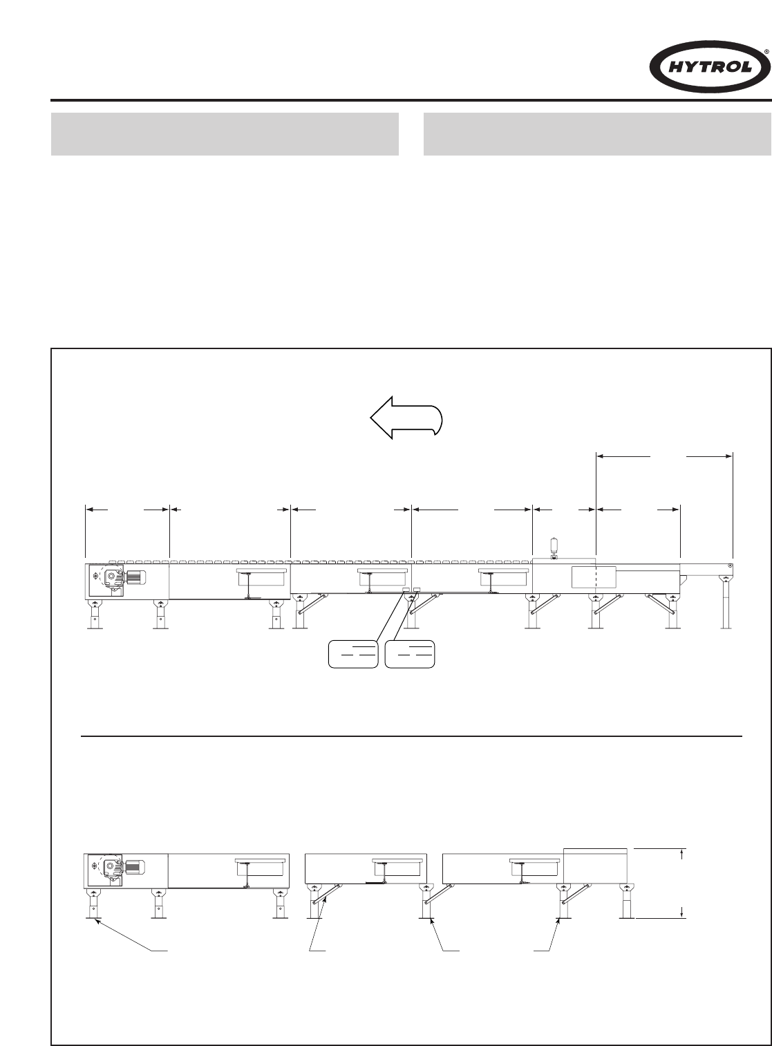
Determine direction of product flow. Figure 6A indi-
cates the flow as related to the drive.
Refer to “Match-Mark” numbers on ends of conveyor
sections. (Figure 6A). Position them in this sequence
near area of installation.
Refiérase a la estructura del edificio para evitar que
cualquier maquinaria, columna o pared obstruya la ubi-
cación del transportador. Revise que el plano sea el
correspondiente.
Determine el flujo del producto. La figura 6A indica el
flujo con relación al motor.
Use las etiquetas de secuencia ubicadas en el extremo
de cada sección de transportador para que sean colo-
cadas en la posición correcta, cerca al área de insta-
lación (Figura 6A).
● Location
1. . .
2. . .
3. . .
1. . .
2. . .
3. . .
CONVEYOR
ITEM TO
HYTROL CONVEYOR CO. INC.
JONESBORO, AR • MANTECA, CA
A
12
CONVEYOR
ITEM TO
HYTROL CONVEYOR CO. INC.
JONESBORO, AR • MANTECA, CA
A
21
DRIVE
(MOTOR)
CANTENARY DIVERT
(DESVIACION CATENARIA)
RETURN DIVERT
FLOW
(DESVIACION DE
RETORNO)
TAIL
(RETORNO)
INTERMEDIATE
DIVERT
(DESVIACION
INTERMEDIA)
INFEED BELT
DRIVE
(BANDA
ALIMENTADORA
MOTRIZ)
INFEED INDUCTION
BELT
(BANDA ALIMENTADORA
DE INDUCCION)
"MATCH-MARK NUMBERS"
(ETIQUETAS DE SECUENCIA DE ARMADO)
DRIVE SUPPORT
(SOPORTE MOTRIZ)
KNEE BRACE
(SOPORTE ANGULAR)
ADJUST TO DESIRED
ELEVATION
(AJUSTE A LA ALTURA
DESEADA)
INTERMEDIATE
SUPPORTS
(SOPORTES INTERMEDIOS)
FIGURE 6A
●
Localización
FIGURE 6B

7
Mark a chalk line on floor to locate center of the conveyor.
Attach supports and vibration pads to all conveyor sections
shown in Figures 6B and 8A. Adjust elevation to required
height. Hand tighten bolts only at this time.
During installation, check to make sure each bed section
is square. Measure the diagonals from corner to corner of
the frame. If they are not equal the frame must be squared.
Attach a come-along or some other suitable pulling device
across longest corners and pull until the section is square.
Place the infeed (tail) section in position.
Install remaining sections, placing end without support on
extended pivot plate of previous section (Figure 6B).
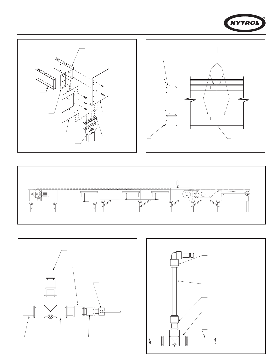
Fasten sections together with splice plates and pivot
plates. (Figure 8A). Hand tighten bolts only at this time.
Check to see that conveyor is level across the width and
length of unit. Adjust supports as necessary.
After all sections have been squared and levelled, tighten
all splice channels and support mounting bolts and lag
support to the floor.
Check alignment of wearstrip at all section joints. Sand
wearstrip as necessary to provide a smooth wear surface
(Figure 8B).
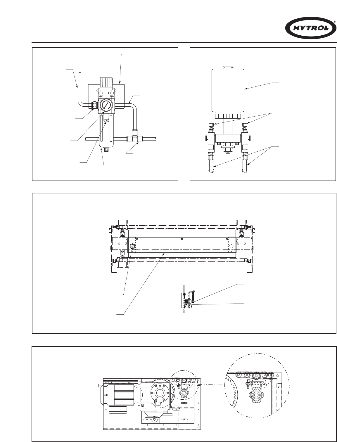
Fasten 1/2” main air line to bottom of conveyor channel
with cable ties (Figure 8C). Connect 3/8”air lines at divert
switches as shown in Figures 8D & 8E.
Connect main air line to the Filter/Regulator, Figure 9A. Set
regulator to working pressure of 60 P.S.I. Install low pres-
sure switch, farthest point from regulator (Figure 8D).
Install electrical controls and wire motor. Verify correct
motor rotation at this time. See Page 10 for electrical con-
trol information.
Check each divert switch to see that it is operating proper-
ly. This must be done before carrying chains are installed.
See instructions on Page 20.
Check proximity switch clearance at each internal safety
switch (Figure 9C). Adjust if necessary.
Install carrying chains per instructions on Page 22.
Adjust pop-up roller assembly at discharge end to optimize
transition of packages from the ProSort to the take away
conveyor. Set pop-up roller proximity switch per Figure 9D.
Install chain oiler at infeed and connect to oil lines as
shown in Figure 9B. Refer to the Lubrication section, page
13 for type of oil required. After mounting, the oiler will need
to be adjusted for proper oiling of mounting chains.
Adjustment may be made using a combination of solenoid
activation time and flow adjustment screws. (Agood rule of
thumb for solenoid adjustment is to turn the oiler on for one
complete chain revolution for every 2 hours of sorter oper-
ation.) The chain on the divert side will typically need slight-
ly more oil which may be accomplished using the flow
adjustment screws. CAUTION: Do not allow oil to drip on
floor.
Locate spurs per instructions on Page 24.
1. . .
2. . .
3. . .
4. . .
5. . .
6. . .
7. . .
8. . .
9. . .
10. . .
11. . .
12. . .
13. . .
14. . .
15. . .
16. . .
17. . .
18. . .
Marque con tiza una línea en el suelo para ubicar el centro
del transportador.
Una los soportes y los protectores de vibración a las sec-
ciones (Figuras 6B y 8A). Ajústelos a la altura requerida.
Apriete los tornillos manualmente.
Durante la instalación revise que cada sección de cama
esté encuadrada. Mida diagonalmente de esquina a
esquina del marco y encuadre si es necesario. Utilize un
tirante de encuadre o algo similar para el ajuste.
Ponga la sección del extremo alimentador.
Instale las secciones restantes poniendo el extremo sin
soporte en la placa pivote de la sección anterior (Fig. 6B).
Sujete las secciones con placas de unión y pivote (Fig 8A).
Apriete los tornillos manualmente.
Revise que el transportador esté nivelado a lo ancho y
largo. Ajuste los soportes como sea necesario.
Después de que todas las secciones hayan sido
encuadradas y niveladas apriete los empalmes de extremo
y los tornillos de montaje. Ancle el soporte al suelo.
Revise la alineación de la guía de cadena en todas las
uniones. Lije las tiras para obtener una superficie suave
(Fig. 8B).
Sujete 1/2” de la línea principal de aire a la parte inferior del
canal del transportador (Fig. 8C). Conecte 3/8” de la línea
de aire en el interruptor desviador (Fig. 8D & 8E).
Conecte la línea principal de aire al Filtro/Regulador (Fig.
9A ). Ajuste el regulador a una presión de 60 PSI. Instale el
interruptor de baja presión lo más alejado posible del regu-
lador (Fig. 8D).
Instale controles eléctricos y conecte el motor. Verifique la
correcta rotación del motor. Ver información eléctrica en la
página 10.
Revise cada interruptor desviador asegurándose de que
funcione correctamente. Esto debe hacerse antes de insta-
lar las cadenas. Ver instrucciones en la página 20.
Revise el espacio libre del interruptor de proximidad en
cada terminal de seguridad (Fig 9C). Ajuste si es necesario.
Instale las cadenas; instrucciones en la Pag. 22.
Ajuste el ensamble de los rodillos de salida facil en la zona
de descarga para optimizar la transición de paquetes del
ProSort a una línea positiva. Ajuste el interruptor (Fig. 9D).
Instale el lubricador de cadena en el extremo alimentador y
conecte las líneas de aceite (Fig. 9B). Refiérase a la sec-
ción de lubricación (Pág. 13) para el tipo de aceite requeri-
do. Después de instalado, el lubricador necesita ser ajusta-
do para la lubricación de cadenas. El ajuste tendrá que ser
hecho usando una combinación de activador del ciclo de
solenoide y tornillos ajustadores del flujo (para el ajuste del
solenoide, el lubricador debe prenderse por una revolución
completa de cadena cada 2 hrs). La cadena del lado
desviador usualmente necesita más aceite que puede
suministrarse por medio de los tornillos ajustadores del
flujo. PRECAUCION: No permita que el aceite gotee al
piso.
Coloque las espuelas. Instrucciones en la página 24.
● Conveyor Set-Up ●
Montaje
1. . .
2. . .
3. . .
4. . .
5. . .
6. . .
7. . .
8. . .
9. . .
10. . .
11. . .
12. . .
13. . .
14. . .
15. . .
16. . .
17. . .
18. . .
8
SECTION JOINT
(SECCION DE UNION)
CONVEYOR CHANNEL
(CANAL DEL
TRANSPORTADOR)
WEARSTRIP CHAIN GUIDE
(GUIA DE CADENA)
CHAIN GUIDES MUST BE
EVEN AT JOINT
(LAS GUIAS DE CADENA
DEBEN SER UNIFORMES
EN LA UNION)
SIDE CHANNEL
(CANAL LATERAL)
VIBRATION PAD
(PROTECTORES
DE VIBRACION)
SPLICE
(EMPALME)
SIDE CHANNEL
(CANAL LATERAL)
PIVOT PLATE
(PLACA PIVOTE)
BED SPACER
(ESPACIADOR
DE CAMA)
BED SPACER
(ESPACIADOR DE CAMA)
1/2" TEE
(TE DE 1/2")
MAIN AIR
(LINEA PRINCIPAL
DE AIRE)
3/8" TO 1/4" REDUCER
(REDUCTOR DE 3/8" A 1/4")
LINE TO VALVE
(LINEA A LA VALVULA)
1/2" TO 3/8" REDUCER
(REDUCTOR DE 1/2" A 3/8")
PRESSURE SWITCH
PRE SET AT 48 PSI
(INTERRUPTOR DE
PRESION AJUSTADO
A 48 PSI)
3/8" LINE
(LINEA DE 3/8")
1/2" to 3/8" REDUCER
(REDUCTOR DE 1/2" A 3/8")
1/2" TEE
(TE DE 1/2")
1/2" MAIN LINE
(LINEA PRINCIPAL DE 1/2")
3/8" FEMALE TO 3/8" MALE
QUICK CONNECT FITTING
PLUG INTO VALVE
(3/8" HEMBRA AL 3/8" MACHO
CONECTE EL ENCHUFE APROPIADO
EN LA VALVULA)
FIGURE 8A FIGURE 8B
FIGURE 8D FIGURE 8E
FIGURE 8C
END SWITCH INTERMEDIATE SWITCHES
9
AIR SUPPLY TO
AIR VALVUES
(SUMINISTRO DE
AIRE A LAS
VALVULAS)
1/2" UNION TEE
(UNION TE DE 1/2")
BOWL GUARD
(TAZON PROTECTOR)
FILTER/REGULATOR
(REGULADOR/FILTRO)
GAUGE
(MEDIDOR)
1/2" NPFT INLET
(ENTRADA DE
1/2" NPFT)
MAIN AIR
SUPPLY
LINE
(SUMINISTRO
PRINCIPAL
DE AIRE)
MOUNTING BRACKET
(FASTEN TO
CONVEYOR CHANNEL)
(PLACA DE MONTAJE
[SUJETAR AL CANAL
DEL TRANSPORTADOR])
OIL CUP
(RECIPIENTE
DE ACEITE)
ADJUSTMENT SCREWS
(TORNILLOS DE AJUSTE)
OIL LINES TO BRUSHES
(LINEAS DE ACEITE
PARA LAS BROCHAS)
PROXIMITY SWITCH
(INTERRUPTOR DE PROXIMIDAD)
SWITCH SENSOR
(INTERRUPTOR DEL SENSOR)
PROXIMITY SWITCH
(INTERRUPTOR DE PROXIMIDAD)
SWITCH SENSOR
(INTERRUPTOR DEL SENSOR)
FIGURE 9A FIGURE 9B
FIGURE 9C
FIGURE 9D

WARNING!
Electrical controls shall be installed and wired by a
qualified electrician. Wiring information for the motor
and controls are furnished by the equipment manufac-
turer.
CONTROLS
Electrical Code: All motor controls and wiring shall conform
to the National Electrical Code (Article 670 or other applica-
ble articles) as published by the National Fire Protection
Association and as approved by the American Standards
Institute, Inc.
CONTROL STATIONS
A) Control stations should be so arranged and located that
the operation of the equipment is visible from them, and
shall be clearly marked or labeled to indicate the function
controlled.
B) A conveyor which would cause injury when started shall
not be started until employees in the area are alerted by a
signal or by a designated person that the conveyor is about
to start.
When a conveyor would cause injury when started and
is automatically controlled or must be controlled from a
remote location, an audible device shall be provided which
can be clearly heard at all points along the conveyor where
personnel may be present. The warning device shall be
actuated by the controller device starting the conveyor and
shall continue for a required period of time before the con-
veyor starts. A flashing light or similar visual warning may be
used in conjunction with or in place of the audible device if
more effective in particular circumstances.
Where system function would be seriously hindered or
adversely affected by the required time delay or where the
intent of the warning may be misinterpreted (i.e., a work
area with many different conveyors and allied devices),
clear, concise, and legible warning shall be provided. The
warning shall indicate that conveyors and allied equipment
may be started at any time, that danger exists, and that per-
sonnel must keep clear. The warnings shall be provided
along the conveyor at areas not guarded by position or loca-
tion.
C) Remotely and automatically controlled conveyors, and
conveyors where operator stations are not manned or are
beyond voice and visual contact from drive areas, loading
areas, transfer points, and other potentially hazardous loca-
tions on the conveyor path not guarded by location, position,
or guards, shall be furnished with emergency stop buttons,
pull cords, limit switches, or similar emergency stop
devices.
ADVERTENCIA!
Los controles eléctricos deben ser conectados e insta-
lados por un electricista calificado. La información sobre
el cableado del motor y los controles será proporcionada
por el fabricante del equipo.
CONTROLES
Código Eléctrico: Todos los controles del motor y las
conexiones deben concordar con el National Electrical Code
(Artículo 670 u otros artículos aplicables) como fue publicado
por la “National Fire Protection Association” y aprobado por el
“American Standards Institute, Inc.”
ESTACIONES DE CONTROL
A) Las estaciones de control deberán estar arregladas y ubi-
cadas de tal forma que el funcionamiento del equipo sea vi-
sible y deberán estar claramente marcadas o señaladas para
indicar la función controlada.
B) Un transportador que pueda causar lesiones cuando es
puesto en marcha, no deberá ponerse en funcionamiento
hasta que los trabajadores en el área sean alertados por una
señal o por una persona designada que indique que el trans-
portador está a punto de arrancar.
Cuando un transportador pueda causar lesiones al arran-
car y sea controlado automáticamente, o tiene que ser contro-
lado desde una ubicación lejana, se deberá proporcionar un
dispositivo sonoro el cual pueda ser escuchado claramente en
todos los puntos a lo largo del transportador donde el per-
sonal pueda estar presente. El dispositivo de advertencia
deberá ser activado por el dispositivo de arranque del trans-
portador y deberá continuar sonando por un determinado
periodo de tiempo antes de que el transportador empiece a
funcionar. Una luz intermitente o una advertencia visual simi-
lar puede ser utilizada con o en lugar del dispositivo sonoro si
es más efectivo en circunstancias particulares.
Donde el funcionamiento del sistema pudiera ser
seriamente obstruído o adversamente afectado por el tiempo
de retardo requerido, o donde el intento de advertencia pueda
ser mal interpretado (ej., un área de trabajo con diversas
líneas de transportadores y los dispositivos de advertencia
relacionados), advertencias claras, concisas y legibles
deberán ser proporcionadas. Las advertencias deberán indicar
que los transportadores y los equipos relacionados pueden ser
puestos en marcha en cualquier momento, que existe un peli-
gro y que el personal debe mantenerse alejado. Estas adver-
tencias deben ser proporcionadas a lo largo del transportador
en áreas que no sean protegidas por la posición o la ubicación.
C) Los transportadores controlados automáticamente y desde
estaciones lejanas, y los transportadores donde las estaciones
de funcionamiento no estén controladas por una persona o
10
● Electrical Equipment ●
Equipo Eléctrico

11
All such emergency stop devices shall be easily identifi-
able in the immediate vicinity of such locations unless
guarded by location, position, or guards. Where the design,
function, and operation of such conveyor clearly is not haz-
ardous to personnel, an emergency stop device is not
required.
The emergency stop device shall act directly on the con-
trol of the conveyor concerned and shall not depend on the
stopping of any other equipment. The emergency stop
devices shall be installed so that they cannot be overridden
from other locations.
D) Inactive and unused actuators, controllers, and wiring
should be removed from control stations and panel boards,
together with obsolete diagrams, indicators, control labels,
and other material which serve to confuse the operator.
SAFETY DEVICES
A) All safety devices, including wiring of electrical safety
devices, shall be arranged to operate in a “Fail-Safe” man-
ner, that is, if power failure or failure of the device itself
would occur, a hazardous condition must not result.
B)
Emergency Stops and Restarts.
Conveyor controls shall
be so arranged that, in case of emergency stop, manual
reset or start at the location where the emergency stop was
initiated, shall be required of the conveyor(s) and associat-
ed equipment to resume operation.
C) Before restarting a conveyor which has been stopped
because of an emergency, an inspection of the conveyor
shall be made and the cause of the stoppage determined.
The starting device shall be locked out before any attempt
is made to remove the cause of stoppage, unless operation
is necessary to determine the cause or to safely remove the
stoppage.
Refer to ANSI Z244.1-1982, American National Standard for
Personnel Protection – Lockout/Tagout of Energy Sources
– Minimum Safety Requirements and OSHA Standard
Number 29 CFR 1910.147 “The Control of Hazardous
Energy (Lockout/Tagout).”
estén más allá del alcance de la voz y del contacto visual de
las áreas de conducción, áreas de carga, puntos de transfe-
rencia y otros sitios potencialmente peligrosos localizados
en la trayectoria del transportador que no tenga protección,
ya sea dada por posición, ubicación, o guardas, deberán ser
equipados con interruptores de parada de emergencia, cor-
dones de parada de emergencia, interruptores de límite o
dispositivos similares.
Todos estos dispositivos de parada de emergencia
deberán ser fácilmente identificables en las cercanías
inmediatas a estos puntos potencialmente peligrosos, a no
ser que estén protegidos dada su ubicación, posición o pro-
tegidos con guardas. Donde el diseño, el funcionamiento, y
la operación de tales transportadores no represente un claro
peligro para el personal, no se requieren los dispositivos de
parada de emergencia.
El dispositivo de parada de emergencia deberá actuar
directamente en el control del transportador concerniente y
no deberá depender de la parada de cualquier otro equipo.
Los dispositivos de parada de emergencia deberán ser insta-
lados de tal forma que no puedan ser anulados desde otras
localidades.
D) Los controles, los actuadores inactivos o no usados y los
cables, deberán ser removidos de las estaciones de control
y de los tableros de mando, junto con los diagramas, indi-
cadores, etiquetas de control y otros materiales obsoletos,
los cuales se prestan para confundir al operador.
DISPOSITIVOS DE SEGURIDAD
A) Todos los dispositivos de seguridad, incluyendo la
conexión de dispositivos eléctricos, deben ser dispuestos
para operar en una manera de “autoprotección”; es decir, si
se presenta una pérdida de corriente o un fallo en el mismo
dispositivo, no debe presentarse una situación peligrosa.
B) Paradas de Emergencia y Reactivadores. Los controles
del transportador deberán estar dispuestos de tal manera
que en caso de una parada de emergencia, se requiera un
activador o arrancador manual en la ubicación donde la
parada de emergencia se presenta para reanudar la
operación del transportador o transportadores y el equipo
asociado.
C) Antes de volver a poner en marcha un transportador que
haya sido detenido por una emergencia, debe revisarse y
determinar la causa de la parada. El dispositivo de arranque
deberá ser bloqueado antes de intentar corregir o remover la
causa que originó la parada, a no ser que la operación del
transportador sea necesaria para determinar la causa o para
solucionar el problema de la parada sin ningún peligro.
Refiérase a ANSI Z244.1-1982, “American National
Standard for Personnel Protection” - Lockout/Tagout of
Energy Sources - Minimum Safety Requirements and OSHA
Standard Number 29 CFR 1910.147 “The Control of
Hazardous Energy (Lockout/Tagout).”

12
OPERATION
A) Only trained employees shall be permitted to operate conveyors.
Training shall include instruction in operation under normal conditions and
emergency situations.
B) Where employee safety is dependent upon stopping and/or starting
devices, they shall be kept free of obstructions to permit ready access.
C) The area around loading and unloading points shall be kept clear of
obstructions which could endanger personnel.
D) No person shall ride the load-carrying element of a conveyor under any
circumstances unless that person is specifically authorized by the owner
or employer to do so. Under those circumstances, such employee shall
only ride a conveyor which incorporates within its supporting structure,
platforms or control stations specifically designed for carrying personnel.
Under no circumstances shall any person ride on any element of a verti-
cal conveyor. Owners of conveyors should affix warning devices to the
conveyor reading Do Not Ride Conveyor.
E) Personnel working on or near a conveyor shall be instructed as to the
location and operation of pertinent stopping devices.
F) A conveyor shall be used to transport only material it is capable of han-
dling safely.
G) Under no circumstances shall the safety characteristics of the convey-
or be altered if such alterations would endanger personnel.
H) Routine inspections and preventive and corrective maintenance pro-
grams shall be conducted to insure that all safety features and devices are
retained and function properly.
I) Personnel should be alerted to the potential hazard of entanglement in
conveyors caused by items such as long hair, loose clothing, and jewelry.
J) As a general rule, conveyors should not be cleaned while in operation.
Where proper cleaning requires the conveyor to be in motion and a haz-
ard exists, personnel should be made aware of the associated hazard.
OPERACION
A) Solo se debe permitir operar los transportadores a empleados entrenados.
El entrenamiento debe incluir instrucciones de operación bajo condiciones
normales y en situaciones de emergencia.
B) Donde la seguridad de los trabajadores dependa de dispositivos de para-
da y/o arranque, éstos deberán mantenerse libres de obstrucciones para per-
mitir un acceso rápido.
C) El área alrededor de los puntos de carga y descarga debe mantenerse
libre de obstrucciones, las cuales podrían poner en peligro al personal.
D) Ninguna persona debe montarse en la parte de conducción de carga de
un transportador bajo ninguna circunstancia al menos que esta persona esté
específicamente autorizada por el dueño o por el supervisor. Bajo estas cir-
cunstancias, el empleado deberá montarse solamente en un transportador
que tenga incorporado dentro de su estructura, plataformas o estaciones de
control especialmente diseñadas para el traslado de personal. Bajo ninguna
circunstancia, persona alguna debe subirse en cualquier parte de un trans-
portador vertical. Los dueños de los transportadores deben añadir señales de
advertencia al transportador con el texto: “No Montarse en el Transportador”.
E) El personal que esté trabajando en o cerca al transportador, deberá ser
instruído en cuanto a la ubicación y operación de los dispositivos pertinentes
de parada.
F) Un transportador deberá ser usado para transportar solo los productos que
sea capaz de manejar seguramente.
G) Bajo ninguna circunstancia deberán ser alteradas las características de
seguridad de un transportador, si tales alteraciones pudieran poner en peligro
al personal.
H) Inspecciones rutinarias deberán llevarse a cabo al igual que programas
preventivos y correctivos de mantenimiento, para asegurar que todos los dis-
positivos y medidas de seguridad sean conservados en buen estado y fun-
cionen correctamente.
I) El personal deberá ser avisado de peligros potenciales como enredos en
transportadores causados por materiales como cabello largo, ropa suelta o
joyas.
J) Como regla general, los transportadores no deberán limpiarse mientras
estén en funcionamiento. Cuando se requiera limpiar el transportador
estando en movimiento y exista posibilidad de peligro, el personal deberá ser
avisado de este riesgo.
● Conveyor Start-Up
Before conveyor is turned on, check for foreign objects that may
have been left inside conveyor during installation. These objects
could cause serious damage during start-up.
After conveyor has been turned on and is operating, check motors,
reducers, and moving parts to make sure they are working freely.
●
Arranque del Transportador
PRECAUCION!
Debido a la cantidad de partes en movimiento del trans-
portador, todo el personal en el área del transportador
necesita ser advertido de que este está a punto de
ponerse en marcha.
Antes de poner en marcha el transportador, revise si hay objetos
ajenos que puedan haber sido dejados dentro del transportador
durante la instalación. Estos objetos pueden causar serios daños
en el arranque.
Después de que el transportador arranque y esté operando, veri-
fique los motores, reductores y partes en movimiento para estar
seguro de que están trabajando libremente.
CAUTION!
Because of the many moving parts on the conveyor, all
personnel in the area of the conveyor need to be
warned that the conveyor is about to be started.
● Operation Safety Precautions ●
Medidas de Seguridad

13
MAINTENANCE
A) Maintenance, such as lubrication and adjustments, shall
be performed only by qualified and trained personnel.
B) It is Important that a maintenance program be established
to insure that all conveyor components are maintained in a
condition which does not constitute a hazard to personnel.
C) When a conveyor is stopped for maintenance purposes,
starting devices or powered accessories shall be locked or
tagged out in accordance with a formalized procedure
designed to protect all person or groups involved with the con-
veyor against an unexpected start.
D) Replace all safety devices and guards before starting
equipment for normal operation.
E) Whenever practical, DO NOT lubricate conveyors while
they are in motion. Only trained personnel who are aware of
the hazard of the conveyor in motion shall be allowed to lubri-
cate.
SAFETY GUARDS
Maintain all guards and safety devices IN POSITION and IN
SAFE REPAIR.
WARNING SIGNS
Maintain all warning signs in a legible condition and obey all
warnings. See Page 3 of this manual for examples of warning
signs.
BEARINGS
A) NO GREASE FITTING—Prelubricated—No lubrication
required.
B) WITH GREASE FITTING—Relubricate approximately
every 10 to 12 weeks with lithium base grease suitable for ball
bearing service.
RECOMMENDED CHAIN LUBRICANT
40° F to 100° F SAE-20W- Non-detergent
20° F to 39° F SAE-10W- Non-detergent
Other aproved alternative lubricant include:
- LPS magnum Teflon Lubricant.
- Engage hightech Lubricant with Teflon.
REDUCERS
See recommendations by manufacturer.
MANTENIMIENTO
A) El mantenimiento, tal como lubricación y ajustes, debe ser
realizado solamente por personal calificado y entrenado.
B) Es importante que se establezca un programa de mante-
nimiento, para asegurar que todos los componentes del trans-
portador sean mantenidos en condiciones que no constituyan
un peligro para el personal.
C) Cuando un transportador esté parado por razones de mante-
nimiento, los dispositivos de arranque o accesorios motorizados
deberán ser asegurados o desconectados conforme a un
procedimiento formalizado, diseñado para proteger de cualquier
arranque inesperado a toda persona o grupos de personas
involucrados con el transportador.
D) Antes de poner en marcha el equipo, vuelva a colocar todos
los dispositivos de seguridad y las guardas.
E) Siempre que sea práctico, NO lubrique los transportadores
mientras se encuentren en movimiento. Solo el personal entre-
nado, que tenga conocimiento de los peligros del transportador
en movimiento, se le permitirá lubricarlos de esta manera.
PROTECCIONES DE SEGURIDAD
Mantenga todas las guardas y dispositivos de seguridad EN SU
POSICION y EN BUENAS CONDICIONES.
SEÑALES DE ADVERTENCIA
Mantenga todas las señales de advertencia en condiciones
legibles y obedézcalas. Remítase a la página 3 de este manual
para ver ejemplos de señales de advertencia.
RODAMIENTOS
A) SIN NECESIDAD DE LUBRICACION—Prelubricados
B) DE LUBRICACION—Lubricar cada 10 a 12 semanas con
aceite a base de litio apropiado para los balines de los rodamien-
tos
LUBRICANTES DE CADENA RECOMENDADOS
40° F a 100° F SAE-20W- No-detergente
20° F a 39° F SAE-10W- No-detergente
Otros lubricantes alternativos aprovados son:
-Lubricante “LPS Magnum Teflon Lubricant.”
-Lubricante “Engage Hightech Lubricant with Teflon.”
REDUCTORES
Refiérase a las recomendaciones de su fabricante.
● Lubrication ●
Lubricación
● Maintenance Safety
Precautions
●
Medidas de Seguridad
en el Mantenimiento

14
A good software package is essential for proper operation
of the ProSort sorter. With proper controls, the sorter will
provide accurate, efficient, reliable sorting for many years.
Inadequate controls, however, may result in poor sorter per-
formance and are the leading cause of “crashes” and other
mechanical failures of the sorter itself.
Every sortation system is different, which means that the
controls for the system are custom and unique to that sys-
tem. These custom controls are usually provided by the
Hytrol distributor, the end user, or a third party.
Hytrol has built into the sorter some of the controls neces-
sary to operate the divert switches, eliminating the need to
control this function externally. Other electrical control com-
ponents are provided with the sorter to allow the external
controls to monitor critical items and to provide an interface
between the electrical controls and the mechanical sorter.
Still other control components must be provided by the sup-
plier of the custom controls package to insure proper sorter
operation.
This section of the manual includes the following informa-
tion for the custom controls provider:
● Controlling the ProSort ●
Controlando el ProSort
Un buen software es esencial para la operación correcta del
ProSort. Con los controles correctos, el clasificador
proveerá precisión, eficiencia y confianza por muchos años.
Controles inadecuados de lo contrario, serán la causa de
una mala clasificación y fallas mecánicas del clasificador.
Cada sistema de clasificación es diferente, por lo tanto cada
sistema tiene controles únicos. Estos controles pueden ser
proporcionados por los distribuidores de Hytrol, los usuarios
o por un terciario.
Hytrol ha incorporado en el clasificador algunos controles
necesarios para operar los interruptores de desviación,
eliminando la necesidad de controlarlos externamente.
Otros componentes de los controles eléctricos también son
proporcionados con el clasificador para permitir que los
controles exteriores detecten detalles críticos y para crear
una relación entre los controles eléctricos y el desviador
mecánico. Aún asi, otros componentes de control deben ser
proporcionados por el proveedor para asegurar una
operación de clasificación adecuada.
Esta sección del manual incluye la siguiente información
para el proveedor de los controles:
A description of the divert switch control components
supplied, their function, and how to interface with
them.
A description of the other control components provid-
ed with the sorter and their intended function.
A description of control components that are not
included with the sorter that must be provided by the
controls supplier.
Some control do’s and dont’s to assist in the design
and installation of the controls package.
1. . .
2. . .
3. . .
4. . .
Una descripción de los componentes del control
desviador provistos, su función y como intercalarlos.
Una descripción de los otros componentes de control
provistos con el desviador y su función primaria.
Una descripción de los componentes de control que
no son incluídos con el desviador y deben ser propor-
cionados por el proveedor de los controles.
Algunas recomendaciones de control para el diseño y
la instalación del paquete de control.
1. . .
2. . .
3. . .
4. . .
Please read this section thoroughly and share this informa-
tion with the controls provider.
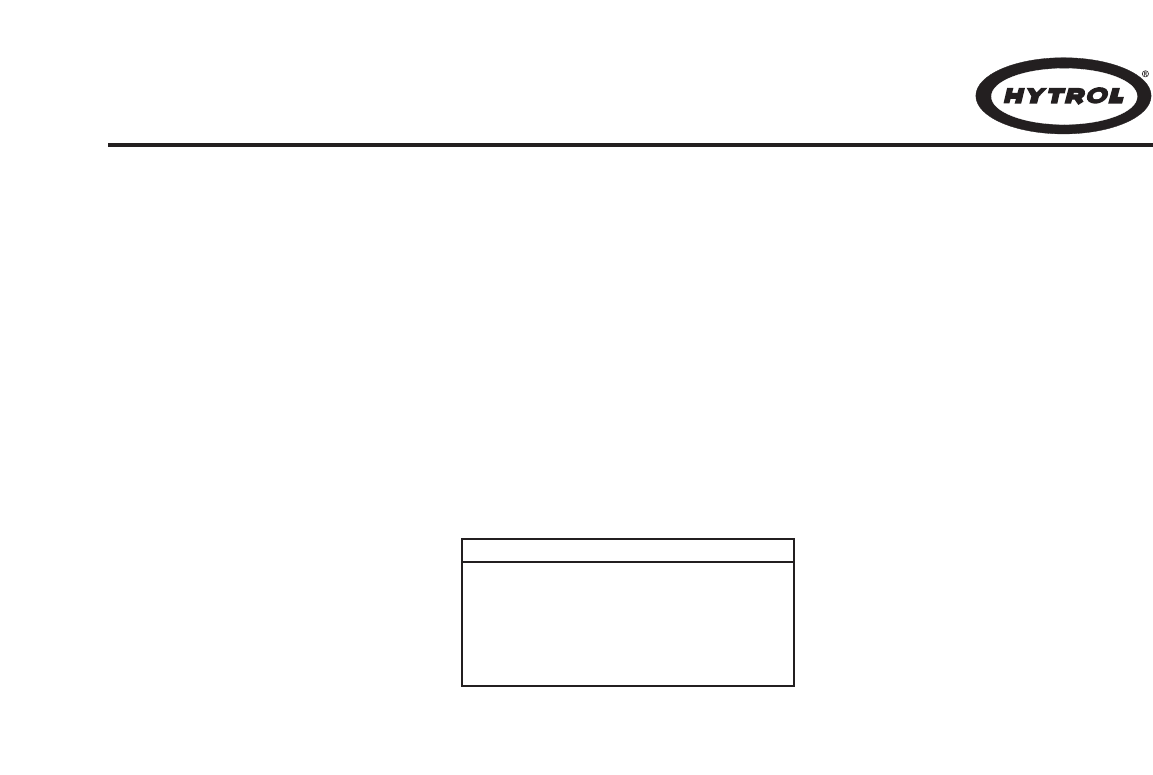
DIVERT SWITCH CONTROL
Proper control of the divert switch is critical to the safe and
reliable operation of the sorter. Failure to properly control
the divert switch is one of the most common causes of
switch damage and can cause “crashes.”
The divert switch functions similar to a switch on a train
track to cause the divert shoes to travel either in a straight-
through, “non-divert” track or diagonally across the sorter
along a “divert track” to push product off of the sorter. When
the switch is in the “home” position, the divert shoes travel
through the switch along the straight-through track. When
the switch is in the “divert” position, the shoes are caused to
move along the divert track.
The transition of the switch between the “home” and “divert”
positions must be accurately timed to prevent sorter crash-
es. Just as a train track switch cannot be safely operated
while a train is passing through the switch, the divert switch
cannot be safely operated while a divert shoe is passing
through the switch. If the movement of the switch mecha-
nism is not timed to occur only when no shoe is present
Por favor lea esta sección completamente y compártala con
el proveedor de los controles.
El CONTROL DESVIADOR
Un control apropiado del desviador es fundamental para
lograr una operación segura y confiable. No controlar
correctamente el desviador es una de las causas más
comunes de daños en el mismo y de “choques” durante la
operación.
La función del desviador es similar a la de un control de
cambio en la vía del tren, permitiendo que los bloques
desviadores viajen tanto en dirección rectilínea por la vía
“sin-desviación”, o diagonalmente por la “vía de desviación”
empujando el producto fuera del clasificador. Cuando el
desviador está en la posición “base”, los bloques
desviadores viajan en dirección rectilínea. Cuando el
interruptor está en la posición “desviar”, los bloques se
moverán por la vía de desviación.
La transición del desviador entre las posiciones “base” y
“desviar” debe ser perfectamente cronometrada para evitar
choques durante la clasificación. De la misma forma que un
control de cambio de vía de tren no puede ser operado con
seguridad mientras el tren está pasando, el desviador no
puede ser operado seguramente cuando un bloque

15
in the switch, the guide pin of the shoe may collide with the
point of the lower switch block, resulting in damage to the
switch and potentially costly downtime.
The ProSort has two control components at each divert
switch that work together to accurately time the divert
switch movement or operation, eliminating the need for the
controls provider to do so. These components are the
smart prox and the high-speed solenoid air valve.
SMART PROX
The “smart prox” is a special inductive proximity sensor
developed exclusively for Hytrol that has the “intelligence”
needed to control the switch timing built-in. The prox has
five wire leads as shown in figure 15A. These leads have
the following functions:
Brown—+24VDC power input to the prox.
Blue—Ground (-) lead for the prox.
Gray—Divert enable input lead for the prox. When a
24VDC (high) signal is given to this lead by the system con-
trols, the prox waits for the next time it detects a divert shoe,
at which time it provides a 24VDC output through the white
lead to the high speed solenoid air valve. The solenoid air
valve then causes the switch to move to “divert” position. All
shoes traveling through the switch will then follow the divert
track as long as the enable signal is active (held high).
When the divert signal is removed (taken low) the prox
waits for the next time it detects a divert shoe, at which time
turn off the output to the solenoid air valve. The switch then
returns to the “home” position, and subsequent shoes will
follow the “non-divert” track. The enable signal to this lead
is the only signal that the system controls must provide
to control divert switching.
White—Solenoid output lead from the prox. This lead is
wired directly to the solenoid air valve. When the enable sig-
nal is present and the prox has sensed the presence of the
next divert shoe, the prox sends a 24VDC (high) output to
this lead to energize the solenoid valve. This output is main-
tained until the enable signal is removed and the prox sens-
es the next divert shoe, then the output is turned off (taken
low).
Black—Standard prox output lead. This lead provides a
24VDC (high) signal each time the prox detects a divert
shoe. This is an optional output and is to be used at the dis-
cretion of the controls provider.
desviador pasa a través del mismo. Si el mecanismo del
desviador no está programado para actuar unicamente
cuando ningún bloque esté presente en el interruptor,
el muñón guia del bloque puede chocar con la punta del
bloque desviador inferior resultando en daños al desviador
y tiempos de paradas potencialmente costosos.
El ProSort tiene dos componentes de control en cada
desviador que trabajan en conjunto para cronometrar con
precisión el movimiento u operación, eliminando la necesi-
dad de que el proveedor lo haga. Estos componentes son
el “smart prox” y la válvula solenoide de aire de alta
velocidad.
“SMART PROX”
El “smart prox” es un sensor inductivo de proximidad
diseñado exclusivamente para Hytrol, que tiene la
“inteligencia” para controlar el tiempo del desviador. El prox
tiene cinco cables direccionales (Fig. 15A). Estos cables
tienen las siguientes funciones:
Café—Corriente de entrada al prox de +24VCD.
Azul—Conductor tierra (-) para el prox.
Gris—Conductor que habilita el desviador para el prox.
Cuando una señal de 24VCD (alta) es dada al conductor
por el sistema de controles, el prox espera a que se detecte
el siguiente bloque desviador y provee una salida de
24VCD a la válvula solenoide a través del conductor blan-
co. La válvula de solenoide es la encargada de hacer que
el desviador cambie a la posición “desviar”. Todos los blo-
ques viajando a través del desviador seguirán la vía
desviadora mientras la señal habilitadora esté activada (en
alto). Cuando la señal desviadora es removida (abajo) el
prox espera detectar el próximo bloque desviador, cerrando
la salida que va a la válvula solenoide. El desviador regre-
sará a la posición “base” y los bloques siguientes seguirán
la vía “sin-desviación”. La señal habilitadora para este
conductor es la única señal que el sistema de controles
debe proporcionar al control desviador.
Blanco—Conductor de salida al solenoide. Este conductor
está conectado a la válvula solenoide. Cuando la señal
habilitadora está presente y el prox ha detectado la
presencia del siguiente bloque desviador, el prox envia una
salida de 24VCD (alta) a este conductor que da energía a
la válvula solenoide. Esta salida continua hasta que la
señal habilitadora sea removida y el prox detecte el
siguiente bloque; luego la salida se cerrará (baja).
BLACK
(NEGRO)
STANDARD PROX OUTPUT (OPTION)
(SALIDA ESTANDAR DEL PROX [OPCIONAL])
WHITE
(BLANCO)
(SOLENOID)
(SOLENOIDE)
DIVERT ENABLE (GRAY)
(HABILITADOR DEL
DESVIADOR [GRIS])
+ BROWN
+ (CAFE)
- BLUE
- (AZUL)
FIGURE 15A

16
HIGH-SPEED SOLENOID AIR VALVE
The solenoid air valve is used to receive the smart prox out-
put signal and provide air to the proper end of the divert
switch cylinder to move and hold the switch in either the
“home” or “divert” positions. The valve used is specially
designed for the high speed operation necessary for proper
divert switch timing.
The two inputs of the solenoid are non-polarized, allowing
either lead to be used as input or ground for the valve. The
solenoid requires 24VDC, 4W to operate.
The solenoid air valve is controlled directly by the smart
prox. Direct control of this valve by the controls package is
not required or advised.
Other Control Components Supplied with the
Conveyor
VARIABLE FREQUENCY DRIVE CONTROLLER
The variable frequency drive (VFD) is a motor controller that
has two functions:
Negro—Conductor de salida estándar del prox. Este con-
ductor provee una señal de 24VDC (alto) cada vez que el
prox detecte un bloque. Esta es una salida opcional y debe
ser usada a discreción del proveedor de controles.
VALVULA SOLENOIDE DE AIRE DE ALTA VELOCIDAD
La válvula solenoide de aire se usa para recibir la señal de
salida del smart prox y proporciona aire al extremo adecua-
do del cilindro del desviador para mover y mantener el
desviador ya sea en “base” o en “desviar”. La válvula está
especialmente diseñada para una operación de alta veloci-
dad necesaria para un tiempo exacto de desviación.
Las dos entradas del solenoide no son polarizadas, permi-
tiendo que cualquier conductor sea usado como entrada o
tierra para la válvula. El solenoide requiere 24VDC, 4W
para operar.
La válvula es controlada por el prox. El control directo de
esta válvula por el paquete de control no es aconsejado.
Otros Componentes de Control Suministrados
con el Transportador
CONTROLADOR MOTRIZ DE FRECUENCIA VARIABLE
La unidad motriz de frecuencia variable (VFD) es un con-
trolador de motor que tiene dos funciones:
It provides a smooth acceleration of the drive motor,
allowing the sorter to slowly “ramp up” to full speed.
This protects the sorter components from the stress of
a full-speed start-up.
It allows the speed of the sorter to be adjusted to
match speed requirements of the system. Also, it
allows the sorter to be operated at a very slow speed
during installation “debugging” and when certain
mechanical components are checked after servicing.
It allows the sorter to be operated at a slower speed
during “off-peak” seasons, reducing energy consump-
tion, noise, and wear.
1. . .
2. . .
3. . .
Proporciona una aceleración suave del motor, permi-
tiendo que el clasificador acelere suavemente hasta
máxima velocidad. Protege los componentes de un
esfuerzo en caso de un arranque repentino.
Permite que la velocidad del clasificador se ajuste
hasta igualar los requerimientos del sistema. También
permite que opere lentamente durante el ajuste y
cuando ciertos componentes mecánicos son revisa-
dos después del mantenimiento.
Permite que el clasificador opere a baja velocidad
durante la baja temporada, reduciendo energia, ruido
y desgaste.
1. . .
2. . .
3. . .
Refiérase al manual de instalación del VFD, proporcionado
con este clasificador para conexiones e instrucciones de
ajustes.
INTERRUPTOR DE PRESION DE AIRE
El interruptor es usado para detectar baja presión de aire.
Si se opera el clasificador con presión de aire menor que
48 PSI se pueden crear daños potenciales al interruptor. Si
la presión del aire se encuentra por debajo de este nivel, el
clasificador debe apagarse hasta que la causa de la dis-
minución de presión sea encontrada y remediada (Fig. 8D).
El interruptor provee un tipo de contacto de salida, el cual
se cierra con presiones de o mayores que 48 PSI y se abre
con presiones menores. El proveedor de los controles
deberá usar ese interruptor para monitorear la presión del
aire y deberá apagar el clasificador si una salida abierta es
detectada en el interruptor de presión.
Refiérase al manual de instalación del interruptor de pre-
sión para instrucciones de como debe ser conectado.
Refer to the VFD manufacturer’s installation manual, pro-
vided with the sorter, for wiring and adjustment instructions.
AIR PRESSURE SWITCH
The air pressure switch is used to detect low operating air
pressure. Operation of the sorter at air pressures under 50
PSI can cause erratic switching and potential switch dam-
age. If air pressure falls below this level, the sorter must be
shut down until the cause of the pressure drop has been
found and remedied (Fig. 8D).
The pressure switch provides a contact-type output which
closes at pressures at or above about 48 PSI and opens
below that air pressure. The system controls provider
should use this switch to monitor air pressure at the sorter
and should shut down the sorter if an open (low) output is
detected from the pressure switch.
Refer to the pressure switch manufacturer’s installation
manual, provided with the sorter, for wiring instructions.
SAFETY PROXIMITY SWITCHES
There are safety switch devices located at various locations
in the sorter to indicate when a divert shoe is out of place,
an obstruction has entered the sorter, or when some other
event has occurred that could cause damage to the sorter
or danger to personnel. These safety switches use normal

17
The normal state of the output of the safety proximity
switches is”on” (high). If a switch detects a problem the sig-
nal is changed to “off” (low). The system controls must be
configured to go to an “emergency stop” condition and shut
down the sorter and related equipment when a problem is
detected. Restart must not be possible until the problem is
corrected and the safety switch that detected the problem is
again “on” (high).
Refer to the proximity switch manufacturer’s installation
manual, provided with the sorter, for wiring instructions.
CATENARY TAKE-UP PHOTO-EYE (OPTIONAL)
The catenary take-up photo-eye monitors the amount of
chain sag occurring in the drive’s catenary area. The photo-
eye is a retro-reflective, light-operate type, positioned in the
catenary so that if the carrying chains allow the slats to sag
below a certain level, the beam of the eye is blocked.
The system controls must be configured to stop the sorter
when the photo-eye beam is blocked (photo-eye output is
“off” or “low”) and provide an indication to the sorter opera-
tor that the chains must be taken up or shortened before
operating the sorter further.
Refer to the photo-eye manufacturer’s installation manual,
provided with the sorter, for wiring instructions.
ENCODER
An encoder is included with the sorter to provide a pulse sig-
nal to be use for product tracking. The encoder provides a
square-wave pulse signal of ten low-to-high and ten high-to-
low transitions per revolution of the sorter infeed shaft, for a
resolution of twenty usable pulses per revolution. This
equates to one pulse (10 “high’s” & 10 “low’s”) for every two
inches of sorter travel.
The encoder requires 24VDC power, and provides a 24VDC
El estado normal de los interruptores de seguridad es “on”
(prendido). Si un interruptor detecta un problema la señal
se cambia a “off” (apagado). El sistema de control debe
estar configurado para “detenerse de emergencia” y apagar
el equipo involucrado cuando se detecte un problema. No
se debe poner en marcha hasta que el problema sea detec-
tado y el interruptor se encuentre de nuevo en “on.”
Refiérase al manual de instalación del interruptor de
proximidad para instrucciones de como conectarse.
FOTO-CELDA CONTROLADORA DE TENSION (OPCIONAL)
La foto-celda monitorea el cedimiento de la cadena en la
zona catenaria motriz. La foto-celda es un retro-reflector
operando con señal de luz, colocado en la catenaria; si las
cadena baja más que el nivel marcado, la señal de la foto-
celda queda bloqueada.
Los controles del sistema deben ser configurados de tal
manera que detengan el clasificador cuando la señal queda
bloqueada (la salida de la foto-celda en posición “off”) e
indique al operador que la cadena debe ser tensionada o
ajustada antes de que el clasificador continue operando.
Refiérase al manual de instalación de la foto-celda, adjunto
con el clasificador, para instrucciones de como conectarlo.
CODIFICADOR
El codificador viene incluído con el clasificador para dar una
señal que sirve para alinear el producto. El codificador da
una señal de pulsación de onda-cuadrada de diez transi-
Interruptores de seguridad de bloque son mecanis-
mos dentro del clasificador que detectan si un bloque
está desalineado. También sirven para detectar obje-
tos ajenos que hayan caido en las tablillas y dentro
del clasificador. Están hechos para detectar proble-
mas en ambas secciones del clasificador (ya sea la
superior o de retorno).
Hay un interruptor localizado en la zona de carga y de
descarga del clasificador. Hay interruptores adi-
cionales a cada 50 pies del clasificador. Por ejemplo,
un clasificador de 70 pies de largo tendrá 3 interrup-
tores; uno de 120 pies tendrá 4 interruptores y asi en
adelante. Estos interruptores adicionales están espa-
ciados igualmente a través de toda la longitud del
clasificador.
El interruptor de seguridad del rodillo de elevación es
usado para detectar cuando un rodillo de transición en
la zona de descarga está “levantado”. Estos rodillos
están diseñados para levantarse cuando un objeto
extraño o un bloque desalineado hace contacto con
ellos.
1. . .
2. . .
Shoe positions safety switches are switch mecha-
nisms inside the sorter that trip if a divert shoe passes
them that is not in its proper track. They are also used
to detect foreign objects that might fall between the
slats and enter the interior of the sorter. They are
made to detect problems on both the upper and return
portions of the sorter.
There is one shoe position safety switch located at the
infeed end and one at the discharge end of the sorter.
There are additional switches included for every 50
feet of sorter length after the first 50 feet. For exam-
ple, a sorter 70 feet long will have a total of 3 switch-
es, a sorter 120 feet long will have a total of 4 switch-
es and so on. These additional switches are spaced
evenly along the sorter’s length.
The pop-up transition roller safety switch is used to
detect when the transition rollers on the discharge end
of the sorter are in the “up” position. These rollers are
designed to pop up if a stray divert shoe or a foreign
object makes contact with them.
1. . .
2. . .
inductive proximity switches as the electrical interface to the
system controls.
There are two types of safety switches in the sorter:
INTERRUPTORES DE PROXIMIDAD DE SEGURIDAD
Hay dispositivos de seguridad colocados en varios lugares
del clasificador para indicar cuando un bloque desviador
está fuera de lugar, hay una obstrucción en el clasificador,
o algo ha ocurrido que puede causar daño. Estos interrup-
tores de seguridad usan interruptores de proximidad tal
como de interface eléctrico para controlar el sistema.
Hay dos tipos de interruptores de seguridad:

18
pulse output.
Refer to the encoder manufacturer’s installation manual.
provided with the sorter, for wiring instructions.
CHAIN OILER SOLENOID
The chain oiler is used to provide automatic lubrication of
the carrying chains during sorter operation. When the oiler
solenoid valve is energized, oil is allowed to gravity feed
from the oiler reservoir, through metering valves, to brush-
es located above the return chains in the sorter.
The system controls should be configured to activate the
chain oiler solenoid for a duration equal to one complete
revolution of the carrying chains about every two hours of
operation. The actual amount of oil applied to the chains is
controlled by the metering screws (see “Conveyor Set-up”
section of this manual).
The chain oiler solenoid requires 24VDC power to operate.
Control Components Not Supplied
with the Conveyor
In addition to the control components supplied with the
ProSort sorter, there are several components that must be
supplied by the system control provider. Hytrol recommends
the following control components be used to protect the
sorter from damage due to product jams or other problems.
ADJUSTABLE INSTANTANEOUS MOTOR OVERLOADS
Instantaneous overloads provide protection against sorter
“hang-ups” by turning off the drive if a sudden increase in
motor current is detected. By adjusting the overload limit to
slightly above the power required to operate the sorter, any
extra load on the motor, such as would be caused by a
product jam or switch malfunction, would cause the sorter to
stop, possibly before significant damage is done to the
equipment.
The instantaneous overloads should be installed in the con-
trol panel for the sorter and sized for the proper power
requirements.
PHOTO-EYES
Photo-eyes are common components in systems controls.
Hytrol recommends that photo-eyes be installed at the fol-
lowing locations to perform listed functions. These are, of
course, in addition to other photo-eyes needed in the sys-
tem.
Induction Photo-eye—A photo-eye mounted at the infeed
point of the sorter. This eye is used to perform the following
functions:
ciones de baja-a-alta y de alta-a-baja por revolución del eje
alimentador, para una resolución de veinte pulsaciones por
revolución. Esto equivale a una pulsación (sea 10 “altas” y
10 “bajas”) por cada dos pulgadas de trayecto del clasifi-
cador.
El codificador requiere 24VCD y provee una salida de pul-
sación de 24VCD.
Para instrucciones en como conectar, vea el manual de
instalación proporcionado con el clasificador.
SOLENOIDE PARA LUBRICACION DE CADENA
El lubricador es utilizado para proporcionar una lubricación
automática de la cadena durante la operación de clasifi-
cación. Cuando la válvula solenoide es energizada, el
aceite de la reserva fluye por gravedad a las válvulas de
medición y luego a las brochas localizadas sobre la cadena
de retorno del clasificador.
El sistema de control debe ser configurado de tal manera
que active el solenoide de lubricación durante una revolu-
ción completa de las cadenas cada dos horas de operación.
La cantidad de aceite aplicada es controlada por los torni-
llos de medición (Vea la sección “Montaje” en este manual).
El lubricador de la cadena requiere de 24VCD.
Componentes de Control no Suministrados
con el Transportador
En adición con los componentes de control suministrados
con el ProSort, hay varios componentes que deben ser
suministrados por el proveedor del sistema de controles.
Hytrol recomienda el uso de los siguientes componentes
para prevenir daños.
AJUSTE DE SOBRECARGAS DEL MOTOR
El sobrecargas provee protección contra daños apagando
el motor cuando se detecta un aumento repentino de
corriente. Al ajustar ligeramente el límite de sobrecarga por
encima de la corriente requerida para operar el clasificador,
cualquier extra carga como una obstrucción o una mala fun-
ción, hará que el clasificador se detenga, posiblemente
antes de causar cualquier daño.
El sobrecargas debe ser instalado en el panel de control
para clasificar y medir la corriente del motor.
FOTO-CELDA
Las foto-celdas son componentes comunes en el sistema
de controles. Hytrol recomienda que las foto-celdas sean
instaladas en las siguientes localidades para que ejecuten
sus funciones. Estas son las foto-celdas, entre otras, que
se necesitan en el sistema.
Foto-celda de Inducción—Una foto-celda colocada en el
punto alimentador del clasificador. Esta es usada para eje-
cutar las siguientes funciones:
Signal the system controls that a particular package has
entered the sorter. From this point forward, the package
must be tracked using the encoder pulses to determine
when it reaches the proper divert location.
Measure the length of the package so that the system
controls may assign the proper number of divert shoes to
the package for diverting. Note: Shoes are to be assigned
for the entire length of the package plus one extra shoe is
to be assigned to the trailing end of the package.
1. . .
2. . .
Avisar al sistema de control que un paquete ha entra-
do en el desviador. Desde este punto en adelante, el
paquete debe ser rastreado usando las pulsaciones
del codificador para determinar cuando alcanze su
punto de transferencia.
1. . .
19
Full Line Photo-eye—Photo-eyes mounted on each divert
lane from the sorter, near the infeed end of that lane. These
eyes are used to signal the system controls that a particular
divert lane is full. The controls should then send any further
packages assigned to that lane to the recirculation line until
the full line photo-eye on that lane no longer indicates the
full condition.
Foto-celda Indicadora de Línea Llena—Las foto-celdas
montadas en la línea de desviación del clasificador lo más
cerca posible al extremo alimentador de las mismas, son
encargadas de dar una señal al sistema de controles cuan-
do una línea de desviación está completamente llena. Los
controles harán que los paquetes designados a esta línea
recirculen hasta que la foto-celda indique que la línea se
encuentra disponible.
Jam/Confirmation Photo-eye—Photo-eyes mounted on
each take-away spur of the sorter, as close to the sorter as
possible. These eyes perform two functions:
Foto-celda de Confirmación o Indicadora de
Obstrucción—Las foto-celdas son colocadas en las
espuelas que van acopladas al clasificador lo más cerca
posible al clasificador. Esta foto-celda tiene dos funciones:
Detect a product jam at the sorter “exit point.” If a
package blocks this photo-eye for a longer time than it
would take for the package to travel past the photo-
eye normally, this indicates that the package is
jammed. The sorter should be stopped and the jam
cleared before restarting the sorter.
Divert confirmation. If a divert signal is given to a par-
ticular divert point, and no package is detected by the
associated jam/confirmation photo-eye, an error has
occurred. The sorter should be stopped and the error
found and corrected before restarting the sorter.
1. . .
2. . .
Detectar un producto atorado en el punto de salida. Si
el paquete bloquea esta foto-celda por más tiempo de
lo debido, esto indica que se encuentra atorado. El
clasificador debe ser detenido y quitar cualquier estor-
bo antes de volver a poner en marcha el clasificador.
Confirmación de desviación. Si la señal de desviación
es dada y ningún paquete ha sido asociado con la
foto-celda, un error ha ocurrido. El clasificador debe
ser detenido y el error encontrado y corregido antes
de ponerlo en marcha.
1. . .
2. . .
Check for the proper gap between packages for safe sort-
ing. It is important to check for the proper gap here, even
if it has been set prior to this point, to insure that the pack-
ages are truly spaced properly. Attempting to sort pack-
ages with too little gap between them can cause jams.
Note: The minimum gap necessary for sorting a package
is a function of the width of the package. The following
charts should be used in checking for proper gap.
Medir la longitud del paquete para que el control de
sistema asigne el número correcto de bloques
desviadores. Nota: El número de bloques estará de
acuerdo a la longitud total del paquete más uno extra
para el extremo del paquete.
Revisar el espacio entre los paquetes para una clasi-
ficación segura. Es importante revisar el espacio
correcto aunque ya haya sido revisado antes de llegar
a ese punto, para asegurar que los paquetes estén
espaciados correctamente. Intentar clasificar los
paquetes con poco espacio entre ellos causará
obstrucciones. Nota: El intervalo mínimo necesario
para la clasificación del paquete es función del ancho
del paquete. La siguientes tablas muestra el intervalo.
3. . .
* W = Ancho del Paquete
Minimum gap = Intervalo mínimo
Nota: Cuando se clasifica hacia ambos lados, el intervalo
mínimo de la tabla debe ser 3 pulgadas mayor.
* W = Package Width
Note: When sorting to both sides, the minimum gap from the
above chart must be increased by 3 in.
ProSort 131 (30° Diverts)
0” < W ≤6” Minimum gap = 6”
6” < W ≤12” Minimum gap = 9”
12” < W ≤18” Minimum gap = 12”
18” < W ≤24” Minimum gap = 15”
2. . .
3. . .

20
After all ProSort sections are installed and aligned, each
divert switch should be checked for proper operations as
follows:
Before air pressure is supplied to the divert switch
solenoid air valve, manually pivot the switch back and
forth between the non-divert and divert position check-
ing for a free and smooth pivoting movement.
Determine and remedy the cause of any switch bind-
ing. For proper switch alignment see figures 21A &
21B. If switch adjustment is necessary, loosen the jam
nut on the cylinder rod. Screw cylinder rod into or out
of rod end to adjust the switch and retighten jam nut.
Turn air pressure on and verify that each divert switch
is in, or moves to, the home (non-divert) position
(Figure 21A).
Check to insure that the smart prox is set properly. The
face of the prox should be set just out of the shoe pin
guide path in the switch guide (Figure 21C).
1. . .
2. . .
3. . .
Después que todas las secciones del ProSort han sido
alineadas e instaladas, revise las siguientes operaciones
de los interruptores desviadores:
● Divert Switch Checklist
Antes de que la presión del aire sea suministrada al
interruptor desviador de la válvula solenoide, manual-
mente mueva el interruptor de la posición no-desviar
a la desviar, revisando que el movimiento sea suave y
ligero. Determine y arregle el problema del interruptor.
Para la correcta alineación vea las figuras 21A & 21B.
Si se necesita ajustar el interruptor, afloje la contra
tuerca del actuador. Atornille la rosca de la varilla del
actuador al extremo apretando la tuerca y ajustando el
interruptor.
Accione la presión de aire y verifique que cada
interruptor se mueva a la posición base (no-
desviar)(Fig. 20A).
Revise que el smart prox funcione correctamente. El
frente del prox no debe obstruir el camino del muñón
guia del bloque desviador (Fig. 21C).
1. . .
2. . .
3. . .
●
Revisión del Interruptor
Do not place 24VDC control wires in the same wire-
way with AC power wires, especially if the AC power
exceeds 240 volts. “Noise” produced in the control
wires by the power wires may produce undesirable
effects.
Do not use optional “standard prox output” of the
smart prox as a substitute for an encoder. The five
inch spacing between divert shoes does not provide
enough tracking resolution to accurately sort pack-
ages.
Do not use manual override operator of the solenoid
air valve to operate a divert switch while the sorter is
running. Doing so bypasses the switch timing controls
and may cause switch damage or a sorter crash.
Do treat the tripping of any safety switch, motor over-
load, or low air pressure signal as an emergency stop.
Inspect the safety switch and other parts of the sorter
to be sure everything is in good working order before
starting or restarting the sorter.
•
•
•
•
No ponga los cables de control de 24VCD en el
mismo lugar que los cables eléctricos CA (especial-
mente si exceden 240 volts) ya que se pueden pro-
ducir efectos indeseables.
No use la “salida prox estándar” para sustituir el
codificador. Esto no proporciona suficiente rastreo ya
que el espacio de cinco pulgadas entre los bloques no
da una resolución para clasificar adecuadamente.
No use el operador manual de la válvula solenoide de
aire para operar el interruptor desviador cuando el
clasificador está corriendo. Hacíendolo pueden igno-
rar el interruptor medidor de tierra causando daños.
Revise la señal de cualquier interruptor de seguridad,
sobrecarga del motor o señal de baja presión como
una parada de emergencia. Inspeccione todas las
partes para asegurar que todo trabaja perfectamente
antes de poner en marcha el clasificador.
•
•
•
•
Some Control Do’s and Dont’s
The following are recommendations to assist in the design
and installation of system controls that are interfacing with
ProSort sorters.
Recomendaciones del Control
Lo siguiente son las recomendaciones para auxiliar en
el diseño e instalación de los sistemas de controles
correspondientes al ProSort.
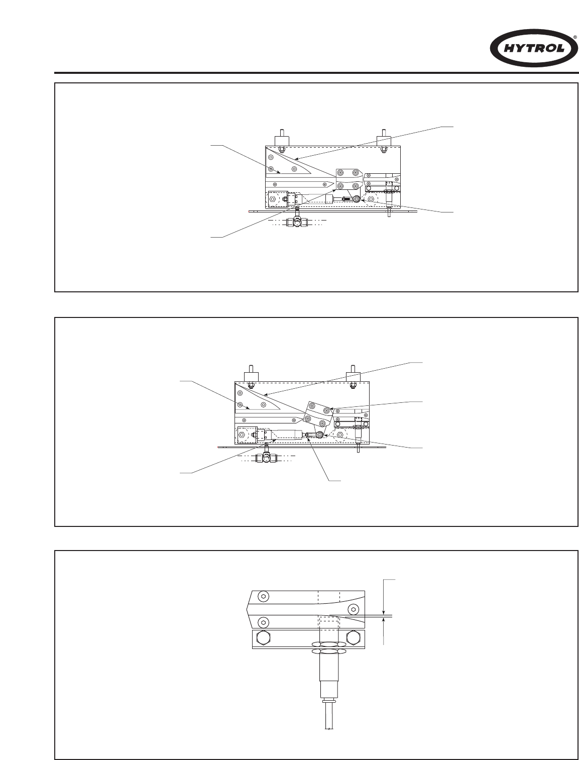
21
LOWER SWITCH BLOCK
(INTERRUPTOR INFERIOR
DE BLOQUEO)
ROD END
(EXTREMO DEL EJE)
UPPER SWITCH BLOCK
(INTERRUPTOR SUPERIOR
DE BLOQUEO)
DIVERT SWITCH (NON DIVERT POSITION)
(INTERRUPTOR DESVIADOR
[POSICION DESVIADORA])
1/32"
LOWER SWITCH BLOCK
(INTERRUPTOR INFERIOR
DE BLOQUEO)
DIVERT SWITCH (DIVERT POSITION)
(INTERRUPTOR DESVIADOR
[POSICION])
ROD END
(EXTREMO DEL EJE)
JAM NUT
(CONTRA TUERCA)
UPPER SWITCH BLOCK
(INTERRUPTOR SUPERIOR
DE BLOQUEO)
CYLINDER ROD
(ACTUADOR)
FIGURE 21A
FIGURE 21B
FIGURE 21C

22
● Carrying Chain Installation ●
Instalación de Cadenas
The carrying chains are shipped on marked spools, cut to
proper length for each ProSort conveyor. Steps for installing
are as follows:
Disconnect electrical power to drive motor to prevent
accidental start up.
Remove the plug from the motor fan guard, exposing
the hex on the motor shaft. Use this shaft to rotate
the motor manually.
Check alignment of chain guides by using two short
pieces of chain with slats assembled to pins.
Chain/tube assembly should slide freely through
chain guides in direction of travel for entire length of
conveyor.
Install carrying chains to both sides of conveyor with
pins pointed inward. Make sure the pins of each
chain are directly opposite each other (Figure 23C).
It will be helpful while installing chains to install one
slat approximately every 4’ to hold chain in guides.
Fasten ends of both chains with connector links as
shown in Figure 23B.
Install two slats onto the extended chain pins on one
side of conveyor. Slide divert shoe onto slats (Figure
23C). Lift opposite chain out of chain guide, so chains
may be spread apart, and insert extended chain pins
into opposite end of slats.
After all slats and divert shoes are installed, tighten
carrying chains with take-up bolts at drive shaft. Be
sure drive and tail shafts are square. Retighten all
drive take-up plate mounting bolts. See Figure 23A
for proper slack in chains.
Manually crank entire carrying chain assembly
through the conveyor to see that it operates freely
and nothing has been dropped into the conveyor dur-
ing installation. Also inspect divert shoes to make
sure all of them have been installed on the correct
centers. If chains are ever shortened it must be in
increments of five inches.
Replace motor fan guard plug.
Reconnect electrical power to drive motor.
Las cadenas son enviadas en carretes marcados, cortadas
a la longitud de cada ProSort. Los pasos al instalar son los
siguientes:
Desconecte la fuente de poder del motor para pre-
venir accidentes.
Remueva el enchufe de la guarda del ventilador del
motor exponiendo el eje hexagonal. Use este eje
para girar el motor manualmente.
Revise la alineación de las cadenas guias utilizando
dos piezas cortas de cadena con tablillas ensam-
bladas a los muñones. El ensamble de la
cadena/tubo debe deslizarse libremente por las
guías de cadena a través de toda la longitud del
transportador.
Instale las cadenas en ambos lados del transporta-
dor con los muñones dirigidos hacia el interior.
Asegúrese de que los muñones de cada cadena
estén directamente opuestos unos a los otros (Fig.
23C). Para facilitar la instalación de la cadena, se
puede instalar una tablilla aproximadamente cada
cuatro pies que sostendrá la cadena sobre las guias.
Junte los extremos de las cadenas con los conec-
tores (Fig. 23B).
Instale dos tablillas dentro de los muñones extendi-
dos a un lado del transportador. Deslize el bloque
desviador en la tablilla (Fig. 23C). Levante la cadena
del lado opuesto de la guia para que las cadenas se
puedan separar e introduzca los pasadores extendi-
dos en el extremo opuesto de las tablillas.
Después de que todos las tablillas y bloques
desviadores son instalados, apriete las cadenas con
tuercas de ajuste en el eje motriz. Asegúrese de que
el eje motriz y el de retorno estén encuadrados.
Apriete las tuercas de montaje. Observe la figura
23A para obtener la tensión correcta de la cadena.
Mueva manualmente la cadena a través de todo el
transportador para asegurarse de que ésta corra
libremente y que no haya caido nada dentro del
transportador durante la instalación. También ase-
gurese de que todos los bloques hayan sido instala-
dos en el lugar correcto. Si hay necesidad de recor-
tar la cadena, debe hacerse en incrementos de cinco
pulgadas.
Ponga el enchufe de la guarda del ventilador.
Conecte la fuente de poder del motor.
1. . .
2. . .
3. . .
4. . .
5. . .
6. . .
7. . .
8. . .
9. . .
10. . .
1. . .
2. . .
3. . .
4. . .
5. . .
6. . .
7. . .
8. . .
9. . .
10. . .
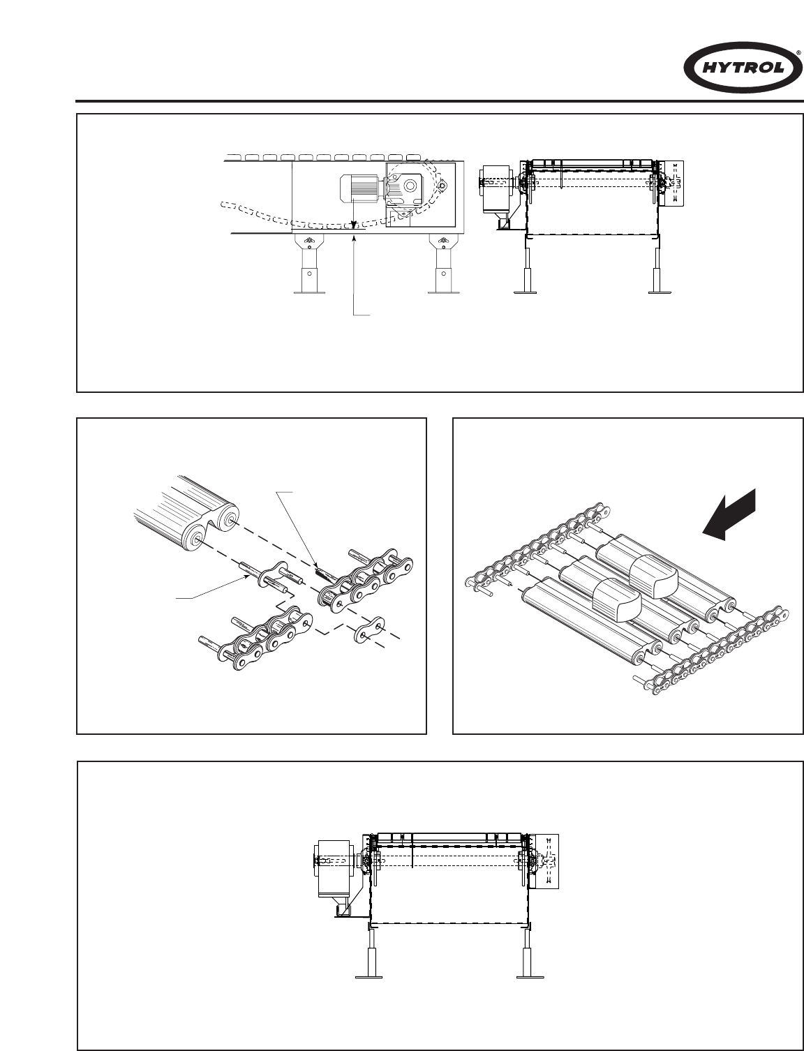
23
CONECTOR LINK
(ENLACE)
CARRYING CHAIN
(CADENA)
FLOW
ALLOW FROM 5" TO 6"
AT INSTALLATION
(PERMITA DE 5 A 6 PULGADAS
DE ESPACIO DURANTE LA
INSTALACION)
FIGURE 23D
FIGURE 23A
FIGURE 23B FIGURE 23C
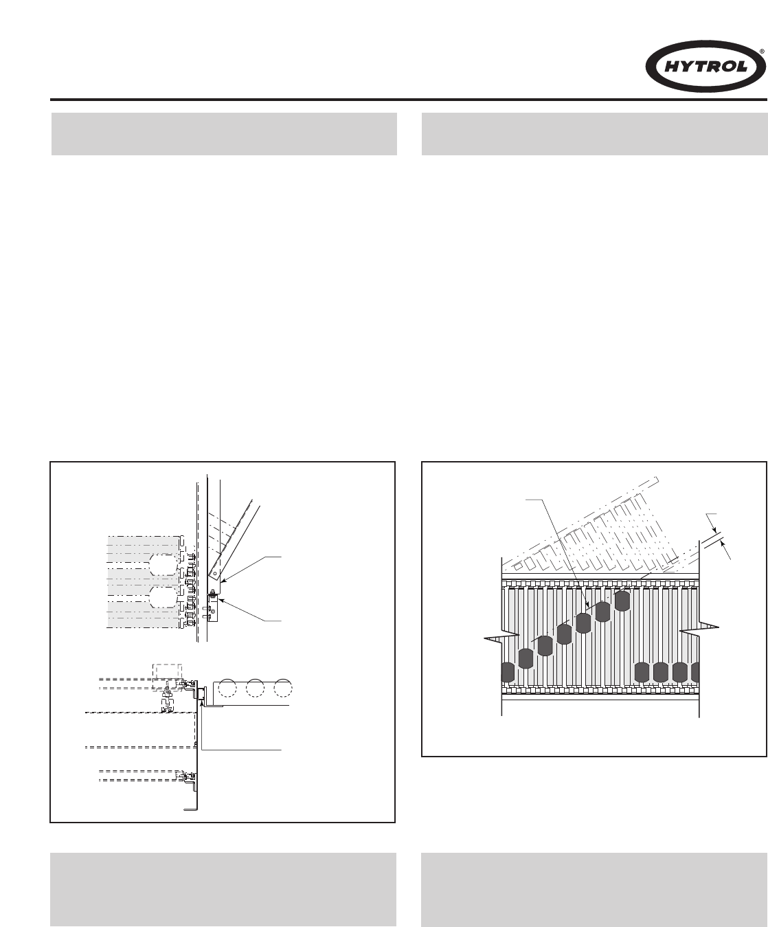
24
● Locating the Spurs ●
Colocando las Espuelas
The take-away spurs must be mounted properly on the
divert sections of the ProSort to insure proper diverting of
product. The following installation guidelines apply to both
powered and gravity spurs.
Attach spurs to the sorter by bolting the spur attach-
ment bracket to the spur mounting nuts in the unistrut
channel on the sorter side channel (Figure 24A).
Support the spurs as required. Hand-tighten bolts only
at this time.
Manually place 3 or more shoes along the divert angle
as shown. Place a straight-edge against the shoes to
determine the location of the “divert line”. Verify that
the distance between the “divert line” and the “BR” of
the spur is at least 1-1/4” inch as shown (Figure 24B).
Position spur vertically so that the spur rollers/skate-
wheels are level with the flight tubes on the sorter.
Tighten mounting bolts.
1. . .
2. . .
3. . .
If guard rails are to be installed on the spurs and/or the spur
side of the sorter, care should be taken to insure that the
guard rails do not interfere in any way with the boxes being
diverted. Particularly, guards should not be installed in a
way that produces a sharp edge or point in the divert area.
● Install Guard Rails at
Divert Locations
●
Instalando las Guardas
Laterales
SPUR PLATE
(PLACA DE LA
ESPUELA)
SPUR ATTACHMENT
BRACKET
(BRAZO SOPORTE
DE LA ESPUELA)
UNISTRUT
(CANAL)
DIVERT LINE
(LINEA DESVIADORA)
2"
Las espuelas de salida deben ser montadas correctamente
en las secciones de desviación del ProSort. La siguiente
información de instalación da unas pautas que se pueden
aplicar en espuelas motorizadas y de gravedad.
Acople la espuela al clasificador atornillando el
soporte de la espuela con las tuercas del canal lateral
del clasificador (Fig.24A). Sopórtelas como se
requiera. Apriete los tornillos manualmente.
Coloque manualmente 3 o más bloques en ángulo
desviador como se muestra. Ponga un nivel al lado de
los bloques para determinar la “línea desviadora”.
Verifique que la distancia entre la “línea” y el “BR” de
la espuela sea mínimo de 1-1/4” pulgadas (Fig. 24B).
Posicione la espuela verticalmente para que los
rodillos/ruedapatín estén nivelados con los tubos en el
clasificador. Apriete los tornillos de montaje.
1. . .
2. . .
3. . .
Si las guardas laterales son instaladas en las espuelas y/o
en el lado clasificador, debe tenerse cuidado de que las
guardas no interfieran de ninguna manera con los produc-
tos desviados. Guardas no deben ser instaladas en el área
de desviación cuando poseen orillas filosas o puntiagudas.
FIGURE 24A FIGURE 24B
DETAIL “A”
(DETALLE “A”)
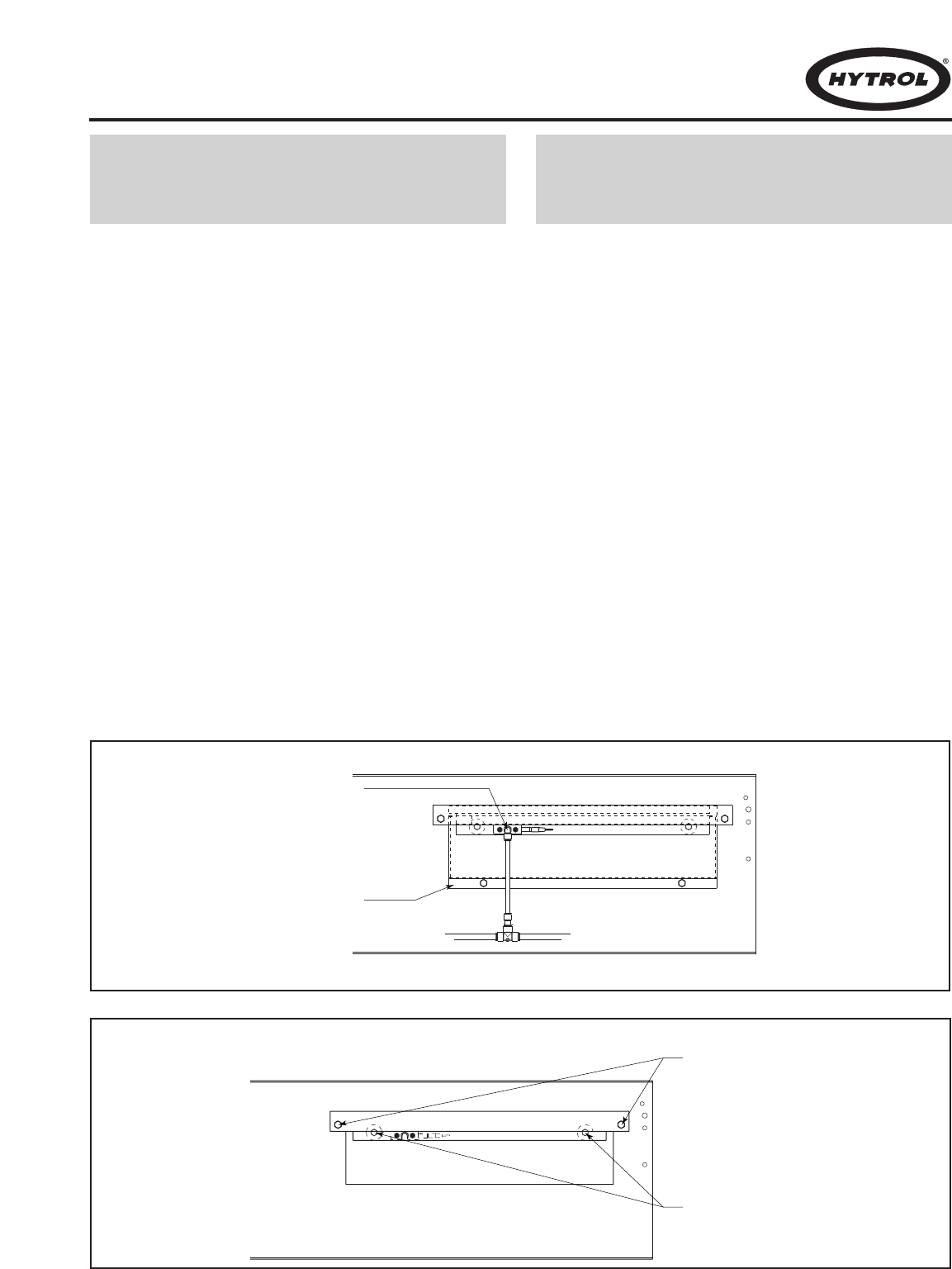
25
The ProSort is designed for easy removal of the divert
switch assembly for maintenance or replacement. In order
to remove the switch assembly follow the following steps.
Remove the cover located on the side of the sorter
channel at the divert switch (Figure 25A).
Unplug the elbow from the fitting on the solenoid air
valve by pushing in on the red flange of the fitting and
then pulling on the elbow.
Disconnect proximity switch connector.
By reaching through the uncovered hole in the side
channel remove the two nuts at the back side of the
switch assembly channel. Then remove the two bolts
on the outside of the sorter channel which hold the
front side of the switch assembly channel up (Figure
25B).
The side of the switch assembly channel may then be
lowered and the entire assembly may be removed
through the opening in the sorter channel.
Check the new switch assembly according to the
“Divert Switch Checklist” on page 20.
Install the new divert switch assembly by reversing the
procedure by which the old assembly was removed.
1. . .
2. . .
3. . .
4. . .
5. . .
6. . .
7. . .
El ProSort está diseñado de tal manera que el interruptor de
desviación pueda ser removido fácilmente. Para remover el
ensamble del interruptor siga los siguientes pasos:
Remueva la cubierta del interruptor localizada en el
lado del canal del clasificador (Fig. 25A).
Desenchufe el codo del encaje de la válvula solenoide
de aire empujando en la franja roja del encaje y jalan-
do el codo.
Desconecte el interruptor de proximidad.
Remueva las dos tuercas localizadas en la parte de
atrás del canal en el ensamble del interruptor, a través
del agujero situado en el canal lateral. Luego remue-
va los dos tornillos de la parte exterior del canal clasi-
ficador que sostienen la parte frontal del ensamble del
interruptor (Fig. 25B).
El lado del canal del ensamble puede ser bajado para
remover el ensamble del interruptor a través de la
abertura del canal del clasificador.
Revise el nuevo ensamble del interruptor de acuerdo
a la “Revisión del Interruptor” de la página 20.
Instale el nuevo ensamble del interruptor revisando el
proceso que se siguió para remover el antiguo.
● Divert Switch Removal
Procedure
●
Remoción del
Interruptor Desviador
REMOVE BOLTS
(REMOVER LOS TORNILLOS)
REMOVE LOCK NUTS
(REMUEVA LAS TUERCAS )
ELBOW FITTING
(ENCAJE DE CODO)
COVER
(CUBIERTA)
FIGURE 25A
FIGURE 25B
1. . .
2. . .
3. . .
4. . .
5. . .
6. . .
7. . .

● Trouble Shooting
26
The following charts list possible problems that may occur in the operation of the ProSort.
TROUBLE SHOOTING DRIVES
TROUBLE CAUSE SOLUTION
Conveyor will not start or shuts off automati-
cally during operation.
Conveyor takes long time to reach speed or
conveyor jerks when starting.
Divert shoes “jump” during diverting.
Inoperative divert switch.
All divert switches inoperative.
1) Jam eye blocked.
2) Tripped internal safety switch.
3) Pop-up rollers “UP”.
4) Proximity switch for internal safety switch
or pop-up rollers mis-adjusted or defec-
tive.
5) Low air pressure.
a) Regulator set low.
b) Air line restricted or broken.
c) Air filter clogged.
d) Compressor problem.
6) Electrical circuits.
7) Variable speed drive mis-adjusted/ defec-
tive.
8) Drive motor defective.
1) Variable speed drive mis-adjusted or
defective.
1) Divert shoe tight on slats.
2) Flight tubes dirty.
3) Flight tubes bent.
4) Switch mis-adjusted.
1) No air pressure to cylinder.
2) Air solenoid valve defective.
3) Proximity switch mis-adjusted or defective.
1) Loss of power to air solenoid valves.
2) Controls failure.
1) Unblock jam eye.
2) Determine cause of tripping: foreign debris, mislocated divert
shoes, etc., and correct problem.
3) Determine reason for rollers popping up and correct problem.
4) Adjust or replace proximity switch.
5) Determine reason for low air pressure and correct problem.
6) Check power and wiring.
7) Refer to variable speed drive manufacturer’s manual for trouble
shooting.
8) Replace motor.
1) Refer to variable speed drive manufacturer’s manual for trouble
shooting.
1) Replace divert shoe or bent slats.
2) Clean surface. (Refer to Preventive Maintenance Details, Page
30.)
3) Replace bend slats.
4) Refer to Divert Switch Checklist, Page 20.
1) Restricted or broken air line.
2) Replace.
3) See page 20 for proper adjusting or replace.
1) Correct problem.
2) Trouble shoot control system.

27
●
Resolviendo Problemas
La siguiente gráfica muestra una lista de posibles problemas que pueden ocurrir durante la operación del ProSort
RESOLVIENDO PROBLEMAS DE TRANSMISION
PROBLEMA CAUSA SOLUCION
El transportador no arranca o se detiene
automáticamente durante la operación.
El transportador se demora en alcanzar la
velocidad deseada o da tirones al arrancar.
Los bloques “brincan” cuando desvian.
El interruptor desviador no está operando.
Todos los interruptores desviadores no están
operando.
1) Sensor de obstrucción bloqueado.
2) El interruptor interno de seguridad está
apagado.
3) Rodillos de elevación están levantados.
4) Interruptores de proximidad para seguri-
dad o para los rodillos de elevación están
desajustados o descompuestos.
5) Baja presión de aire.
a) El regulador está ajustado muy bajo.
b) Línea de aire está obstruida o cortada.
c) Filtro de aire tapado.
d) Problema en el compresor.
6) Circuitos eléctricos.
7) La velocidad variable de la unidad motriz
está desajustada o defectuosa.
8) La unidad motriz está defectuosa.
1) Unidad motriz de velocidad variable está
desajustada o defectuosa.
1) Bloque desviador apretado en las tablillas.
2) Tubos sucios o enpolvados.
3) Tubos doblados.
4) Interruptor desajustado.
1) El cilindro no recibe presión de aire.
2) Válvula solenoide de aire defectuosa.
3) Interruptor de proximidad defectuoso/desalineado.
1) Válvulas solenoides sin energía para operar.
2) Falla en los controles.
1) Despeje la obstrucción del sensor.
2) Determine las causas de la detención: aparatos extraños, bloques
desacomodados, etc., y corrija el problema.
3) Determine la causa de la salida de los rodillos y corríjala.
4) Ajuste o reemplaze el interruptor de proximidad.
5) Determine la razón de la baja presión y corríja el problema.
6) Revise la fuente de poder y su conexión.
7) Para ajustar la velocidad variable del motor diríjase al manual de
su fabricante.
8) Reemplace el motor.
1) En caso de problemas, diríjase al manual del motor de velocidad
variable.
1) Reemplaze el bloque desviador o las tablillas dobladas.
2) Limpie la superficie. (Refiérase a la página 30)
3) Reemplaze la tablilla doblada.
4) Diríjase a la revisión del interruptor de desviación (Pag. 20).
1) Linea del aire está obstruida o cortada.
2) Reemplazar.
3) Diríjase a la página 20 para ajustar o reemplazar correctamente.
1) Corrija el problema.
2) Resuelva los problemas del control de sistema.
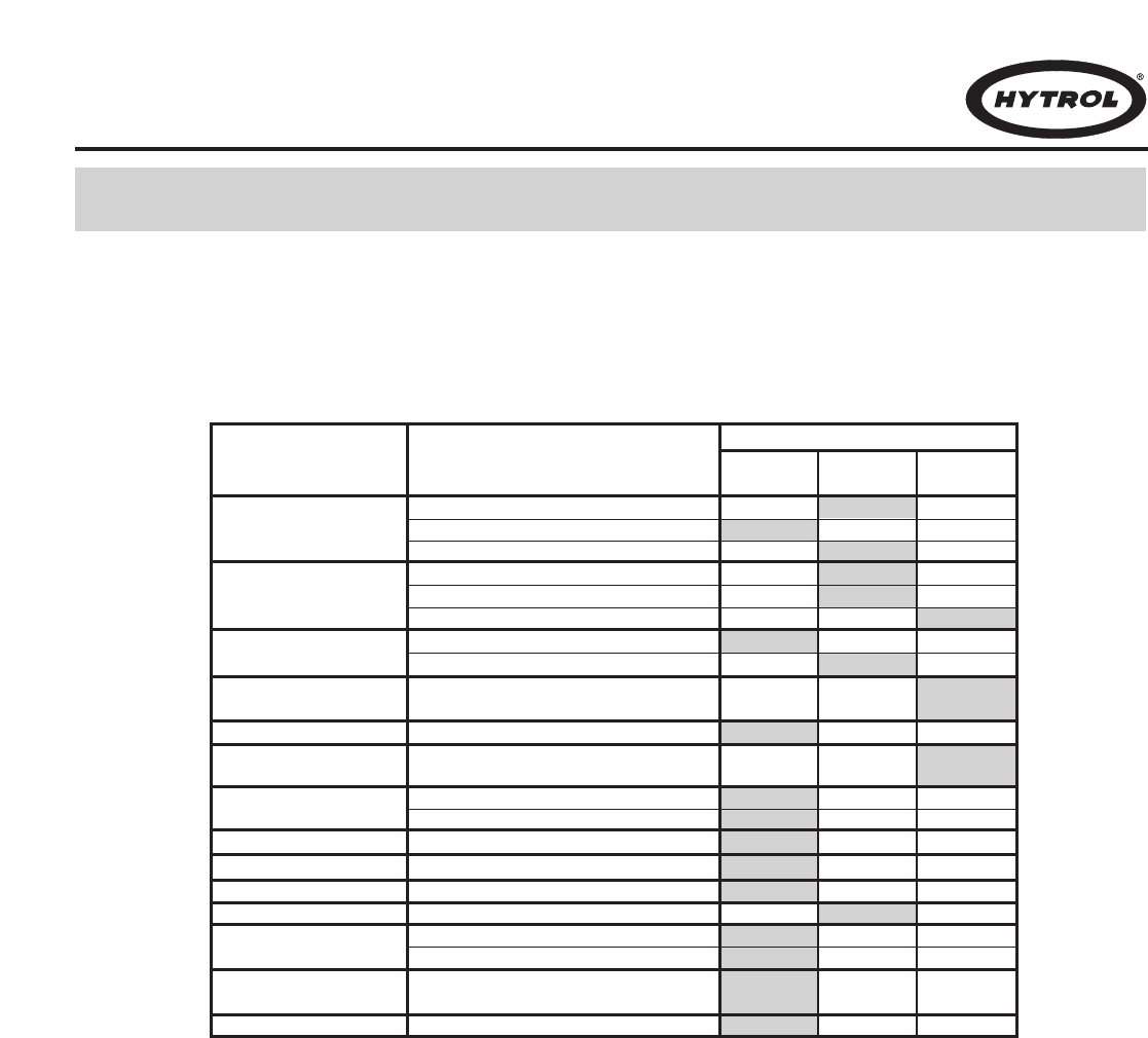
28
The following is a general maintenance checklist which covers the major components of your conveyor.
This will be helpful in establishing a standard maintenance schedule.
● Preventive Maintenance Checklist
Check Noise
Check Temperature
Check Mounting Bolts
Check Noise
Check Temperature
Check Oil Level
Check Lubrication
Check Tension (See Page 22)
Check Alignment with Chain Guards
Check for Wear
Check Physical Condition
Check Physical Condition
Check Operation
Check Oil Level
Check Pressure (60 P.S.I. Normal)
Check Physical Condition
Check All Loose Bolts, etc. tightened
Check Physical Condition
Check Operation
Check Physical Condition
Check Physical Condition
SCHEDULE
SUGGESTED ACTIONCOMPONENT
MOTOR
REDUCER
FLIGHT TUBES
CHAIN OILER
AIR REGULATOR
AIR FILTER
STRUCTURAL
DIVERT SHOES
DIVERT ANGLES
UPPER & LOWER
SWITCH BLOCKS
DIVERT
SWITCHES
CARRYING CHAINS
CARRYING CHAIN
SPROCKETS
CARRYING CHAIN
GUIDES
Weekly Monthly Quarterly
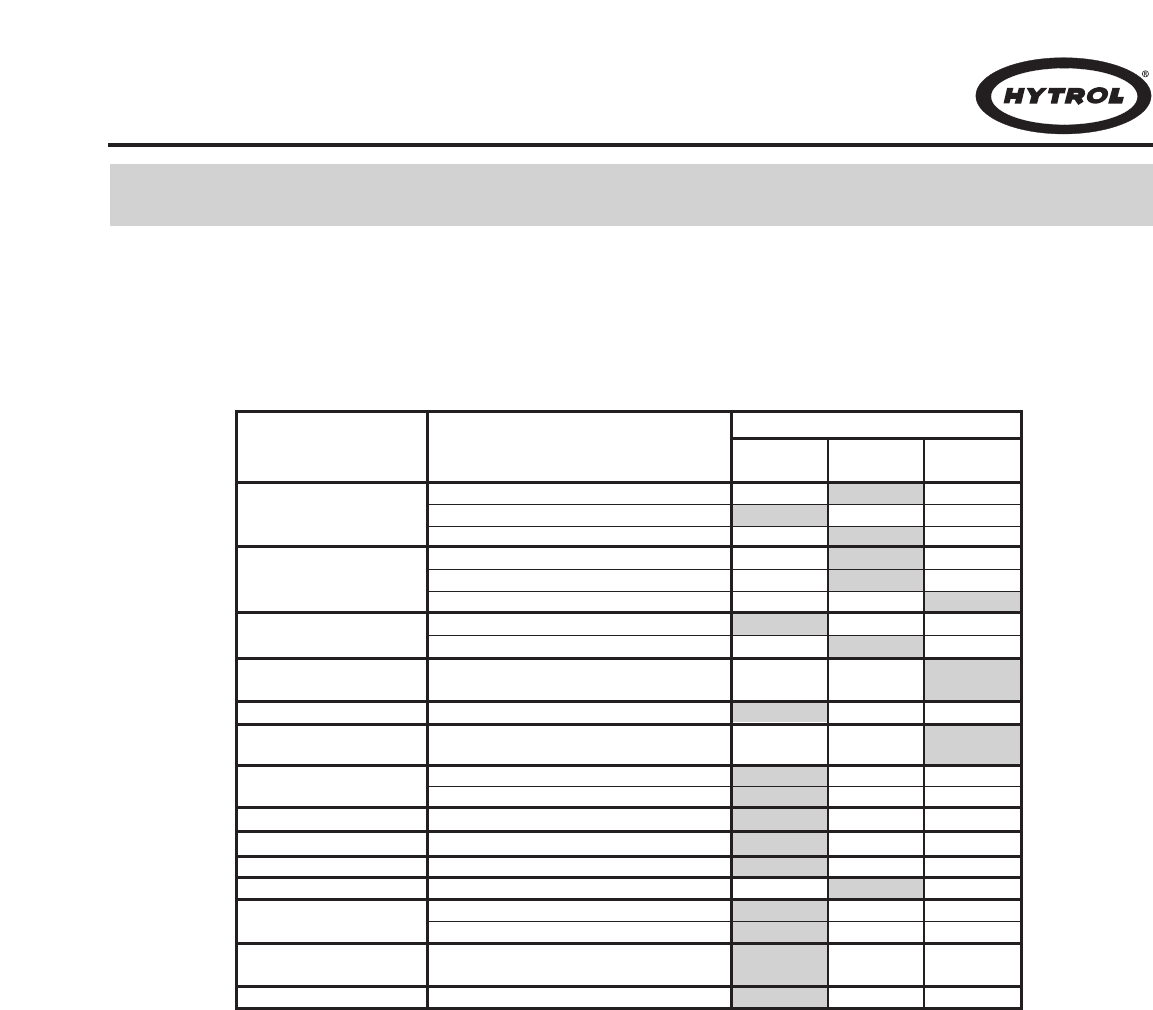
29
La siguiente es una lista de verificación del mantenimiento preventivo, la cual cubre los principales componentes de su
transportador. Esta será útil para establecer un programa estándar de mantenimiento.
●
Lista de Mantenimiento Preventivo
Revisar el Ruido
Revisar la Temperatura
Revisar los Tornillos de Montaje
Revisar el Ruido
Revisar la Temperatura
Revisar el Nivel de Aceite
Revisar la Lubricación
Revisar la Tensión (Ver Pag. 22)
Revise su alineación con la guarda cadena
Revise el Desgaste
Revise la Condición Física
Revise la Condición Física
Revise la Operación
Revise el Nivel de Aceite
Revise la Presión (Normalmente 60 PSI)
Revise la Condición Física
Revise si hay Tornillos Sueltos, etc.
Revise la Condición Física
Revise la Operación
Revise la Condición Física
Revise la Condición Física
HORARIO
ACCION SUGERIDACOMPONENTE
MOTOR
REDUCTOR
TUBOS
LUBRICADOR
REGULADOR DE AIRE
FILTRO DE AIRE
ESTRUCTURA
BLOQUES
DESVIADORES
ANGULO DESVIADOR
INTERRUPTOR DESV.
INFERIOR Y SUPERIOR
INTERRUPTORES
DESVIADORES
CADENAS
CATARINAS DE LAS
CADENAS
GUIAS DE CADENA
Semanal Mensual Trimestral

30
Carrying Chains—Check lubrication. Chains will appear
moist properly lubricated.
Slats—Check physical condition. Check slats for cleanli-
ness and straightness. Slats may be cleaned by wiping with
degreaser type solvent such as a denatured alcohol.
Replace any bent slats.
Divert Switches—Check physical condition. Switches must
be kept in good physical condition and free and clear of all
foreign matter.
Check operation. Check for any loose switches or improp-
erly adjusted switches. Check physical condition of upper
and lower switch blocks. Pay particular attention to the point
of the lower switch block nearest the switch.
Divert Shoes—Check physical condition. Look for any
damaged divert shoes and replace. Check operation. Divert
shoes should slide freely on slats. Remedy cause of any
binding. Replace any damaged shoes.
Divert Angles—Check for any bent areas. Check for loose
or missing wearstrip.
● Preventive Maintenance
Details
Cadenas—Revisar lubricación. Las cadenas deben verse
húmedas, propiamente lubricadas.
Tablillas—Revise su condición física. Revise la limpieza y
rectitud de las tablillas. Las tablillas se pueden limpiar con
solvente desengrasador tal como alcohol desnaturalizado.
Reemplace cualquier tablilla doblada.
Interruptores de Desviación—Revise su condición física.
Los interruptores tienen que estar en buenas condiciones y
libres de cualquier material ajeno.
Revise su operación. Revise que los interruptores no estén
flojos o mal ajustados. Revise la condición física de los
interruptores superiores e inferiores. Ponga especial aten-
ción al punto inferior del bloque cerca al interruptor.
Bloques Desviadores–Revise su condición física. Busque
si hay bloques dañados y reemplácelos. Revise la
operación. Los bloques deben deslizarse suavemente por
las tablillas. Reemplace los dañados.
Angulos Desviadores—Revise si hay áreas dobladas.
Revise si la tira de protección esta floja o extraviada.
● Detalles de
Mantenimiento
31
Included in this manual are parts drawings with complete
replacement parts lists. Minor fasteners, such as nuts and
bolts, are not included.
When ordering replacement parts:
Contact Dealer from whom conveyor was purchased
or nearest HYTROL Distributor.
Give Conveyor Model Number and Serial Number or
HYTROL Factory Order Number.
Give Part Number and complete description from Parts
List.
Give type of drive. Example—8” End Drive, 8” Center
Drive, etc.
If you are in a breakdown situation, tell us.
1. . .
2. . .
3. . .
4. . .
5. . .
Dibujos de las partes con listas completas de las refac-
ciones están incluidos en este manual. Aseguradores
menores, como tornillos y tuercas no están incluídos.
Para ordenar partes de repuesto:
Contacte la persona que le vendió el transportador o
el distribuidor de Hytrol más cercano.
Proporcione el Modelo del Transportador y el Número
de Serie o Número de la Orden de Fabricación.
Proporcione el Número de las partes y descripción
completa de la Lista de Partes.
Proporcione el tipo de motor. Ejemplo—Unidad Motriz
de 8” en el Extremo, Unidad Motriz Central 8” , etc.
Si está en una situación crítica, comuníquese con
nosotros inmediatamente.
1. . .
2. . .
3. . .
4. . .
5. . .
Hytrol Conveyor
Company, Inc.
JONESBORO, ARKANSAS MANTECA, CALIFORNIA
Model
ProSort 100
SERIAL # 978747
● How to Order
Replacement parts
●
Como Ordenar Partes
de Repuesto
HYTROL Serial Number
(Located near Drive on
Powered Models).
Número de Serie HYTROL
(Localizado cerca a la
Unidad Motriz en los
modelos motorizados).
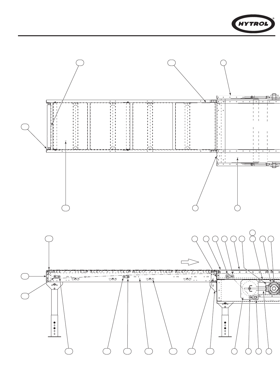
32
72
79
86
109 118
105
111
114
107
108 108 106 103 104 112 113
110
94
73 90 92 96
8389918193 88 859887
●
Model ProSort 131 Parts Drawing
Dibujo de Partes del Modelo ProSort 131
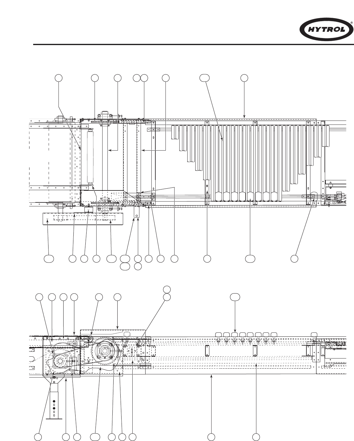
33
39468297 6380 6568 38
66 60 64 555862 63
69
67
116
119
119
102
117101100
123
75 95 56 53 54
5984777899 76 70
57 6174
●
Model ProSort 131 Parts Drawing
Dibujo de Partes del Modelo ProSort 131
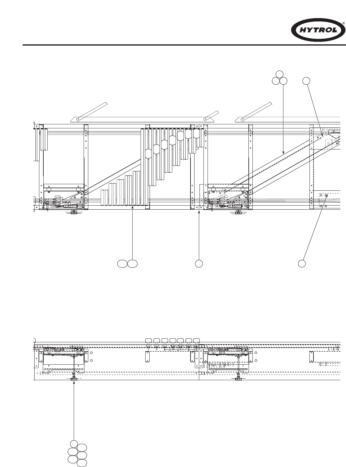
34
45 52
49 5148
35
124
126125
122
127
121120
71
●
Model ProSort 131 Parts Drawing
Dibujo de Partes del Modelo ProSort 131
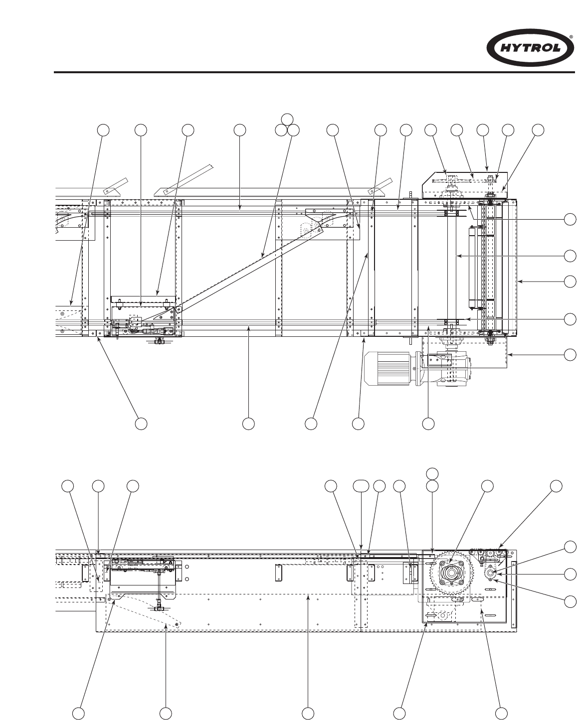
35
414027 2
34 41 30 18 5 23 25 17 24 7
26
12
15
3
8
50 32 3329
28
115
31 49 42 9 6
22
16
14
132111
10
37 347 36 21 22
●
Model ProSort 131 Parts Drawing
Dibujo de Partes del Modelo ProSort 131

36
●
Model ProSort 131 Parts List
Lista de Partes del Modelo ProSort 131
Ref. No. Part No. Description
1 B-23749 Side Angle LH or RH.
2 B-23703 Bed Spacer
3 B-23750 End Plate (Specify OAW)
4 B-23751 Pin Guide
5 B-23752 Pin Guide
6 B-23753 Side Wearstrip
7 — Bearing Mounting Channel
— B-23754 Left Hand
— B-23755 Right Hand
8 — Drive Bearing Mounting Channel
— B-23756 Left Hand
— B-23757 Right Hand
9 — Torque Arm Channel
— B-23758 KA47 Eurodrive Reducer
— B-23759 KA77 Eurodrive Reducer
10 B-23760 Tail Wearstrip Angle
11 B-23761 Chain Wearstrip
12 — Drive Shaft
— B-23762 KA47 Eurodrive Reducer
— B-23768 KA77 Eurodrive Reducer
13 B-23763 Transition Roller Assembly (Specify OAW)
14 B-23764 Transition Drive Shaft (Specify OAW)
15 B-23734 Shoe Retainer
16 B-18783 Transition Roller Driver
17 B-23767 O-Ring Guard
18 B-23739 Spacer
19 B-23766 Unistrut
20 B-23765 Take-Up Lug
21 010.2052 1-15/16 Bore 4 Bolt Bearing
22 010.0022 1” Bore 2 Bolt Bearing
23 020.150 Sheave 8.7” PD
24 020.130 Sheave 2.5” PD
25 090.25465 O-Ring Driver
26 028.560 Sprocket
27 B-23840 Side Angle LH or RH
28 B-23795 Divert Angle (Specify OAW)
29 B-23796 Wearsrip Tie Strap (Specify OAW)
30 B-23797 Y-Block Plate
31 B-23798 Cover Plate
32 B-23799 Switch Support Channel
33 B-23833 Divert Angle Wearstrip (Specify OAW)
34 — Switch Assembly
— B-23593 Left Hand
— B-23594 Right Hand
35 B-23844 Return Divert Angle (Specify OAW)
36 B-23842 Splice Plate
37 B-23834 Spur Mounting Channel (Unistrut)
38 B-23707 Pin Guide Splice Plate
39 B-23708 Pin Guide Spacer
Ref. No. Part No. Description
40 B-23835 Pin Guide (Specify OAW)
41 B-23836 Pin Guide (Specify OAW)
42 B-23841 Side Wearstrip (Specify OAW)
43 — Y-Block
— 092.1785 Left Hand
— 092.1795 Right Hand
44 092.1837 Catenary Block
45 B-23794 Side Angle Rh or LH
46 B-18450 Oiler Mounting Bracket
47 B-16949 Splice Plate
48 B-23845 Return Wearstrip Tie Strap (Specify OAW)
49 B-23846 Return Divert Angle Wearstrip (Specify OAW)
50 B-23847 Pin Guide Block Plate
51 092.1805 Return Block
52 092.181 Pin Guide Block
53 B-23702 Side Channel (Specify OAL)
54 B-23705 Chain Wearstrip Mtg. Angle (Specify OAL)
55 B-23706 Spur Mounting Channel (Specify OAL)
56 B-23732 Infeed Tail Side Angle Weldment
57 B-23733 Infeed Tail Take-Up Plate Weldment
58 B-23703 Bed Spacer Weldment (Specify OAW)
59 B-16934 End Cover Weldment RH or LH
60 B-23735 Idler Sprocket
61 B-23743 Pin Guide Bottom
62 B-23736 Infeed Tail Shaft (Specify OAW)
63 B-23737 Tail Wearstrip Angle
64 B-23738 Chain Wearstrip for Infeed/Discharge Tail Assy. LH or RH
65 B-23739 Pin Guide Spacer
66 — End Plate
— B-23740 Left Hand
— B-23741 Right Hand
67 B-18469 Oiler Brush Mounting Bracket
68 092.1815 Infeed Guide
69 095.150 Oiler
70 095.155 Oiler Brush
71 094.1464 Plug Reducer 3/8” to 1/4”
72 B-23712 Drive Side Plate RH or LH
73 B-23713 Cover Assembly RH or LH
74 B-23723 Pulley Plate Assembly
75 B-23714 8” Drive Pulley (Specify OAW)
76 — 2-1/4” Dia. Pulley
— B-23168-033 26 in. OAW
— B-23168-039 32 in. OAW
— B-23168-045 38 in. OAW
— B-23168-051 44 in. OAW
77 — Slave Guard
— B-23715 Left Hand
— B-23716 Right Hand
See Page 31 for Information on How To Order Replacement Parts
Recommended Spare Parts Highlighted in Gray
Vea la Página 31 para información sobre como ordenar partes de repuesto
Las Partes de Repuesto Recomendadas se Resaltan en Gris

37
●
Model ProSort 131 Parts List
Lista de Partes del Modelo ProSort 131
Ref. No. Part No. Description
78 B-23717 Slave Guard Cover
79 B-23718 Drive End Channel (Specify OAW)
80 B-23175 Pulley Mounting Bracket
81 B-23176 induction Drive Channel
82 B-23719 Slave Guard Mounting Bracket
83 — Bolt in Slider Pan
— B-23294-033 26 in. OAW
— B-23294-039 32 in. OAW
— B-23294-045 38 in. OAW
— B-23294-051 44 in. OAW
84 — Nip Point Guard
— B-23295-033 26 in. OAW
— B-23295-039 32 in. OAW
— B-23295-045 38 in. OAW
— B-23295-051 44 in. OAW
85 B-23720 6” Take-Up Pulley (Specify OAW)
86 B-04161 Bearing Spacer
87 B-09148 Bearing Guide Spacer
88 B-20935 Take-Up Plate Assembly
89 B-00944 7/16” Hex idler Bracket
90 B-04842 11/16” Hex Idler Bracket
91 — 2-1/8” Roller
— B-23118-015 26 in. OAW
— B-23118-021 32 in. OAW
— B-23118-027 38 in. OAW
— B-23118-033 44 in. OAW
92 B-15299 2-1/2” Roller (Specify BR)
93 B-23299 Butt Coupling LH or RH
94 B-23721 Top Drive Guard (Slave Side)
95 B-23722 Lower Drive Guard
96 B-23302 Take-Up Bolt
97 B-23304 Idler Plate
98 010.203 1-7/16” 4-Bolt Bearing
99 010.2045 1-11/16” 4-Bolt Bearing
100 028.85120 48PTH8-35SD 1-11/16” Bore
101 028.85320 56PTH8-35SK 1-1/2” Bore
102 028.8865 1280PTH8M Belt 35mm Wide
103 — Side Channel
— B-21500 2 ft. Long
— B-21501 2 ft. 3 in. Long
— B-21502 2 ft. 6 in. Long
— B-21170 2 ft. 9 in. Long
— B-21503 3 ft. Long
— B-21504 3 ft. 3 in. Long
— B-21505 3 ft. 6 in. Long
— B-21506 3 ft. 9 in. Long
— B-04923 4 ft. Long
— B-21507 4 ft. 3 in. Long
— B-21508 4 ft. 6 in. Long
— B-21509 4 ft. 9 in. Long
— B-02636 5 ft. Long
— B-23308 5 ft. 3 in. Long
— B-23309 5 ft. 6 in. Long
— B-23310 5 ft. 9 in. Long
— B-05494 6 ft. Long
— B-23311 6 ft. 3 in. Long
— B-23312 6 ft. 6 in. Long
— B-23313 6 ft. 9 in. Long
Ref. No. Part No. Description
— B-21606 7 ft. Long
— B-23314 7 ft. 3 in. Long
— B-12082 7 ft. 6 in. Long
— B-23315 7 ft. 9 in. Long
— B-09908 8 ft. Long
— B-23568 8 ft. 3 in. Long
— B-23569 8 ft. 6 in. Long
— B-23570 8 ft. 9 in. Long
— B-21607 9 ft. Long
— B-23571 9 ft. 3 in. Long
— B-23572 9 ft. 6 in. Long
— B-21607 9 ft. Long
— B-23571 9 ft. 3 in. Long
— B-23572 9 ft. 6 in. Long
— B-23573 9 ft. 9 in. Long
— B-02633 10 ft. Long
104 B-03916 Bed Spacer (Specify BR)
105 — Bolt in Pan
— B-22241 16-1/2 in. Long
— B-22242 19-1/2 in. Long
— B-22243 22-1/2 in. Long
— B-22244 25-1/2 in. Long
— B-22224 28-1/2 in. Long
— B-22245 31-1/2 in. Long
— B-22241 16-1/2 in. Long
106 — 1.9 O.D. Galv. Roller Assembly
— B-01982-120 15 in. BR
— B-01982-168 21 in. BR
— B-01982-216 27 in. BR
— B-01982-264 33 in. BR
— B-01982-312 39 in. BR
107 — 2-1/8” Roller
— B-01982-120 15 in. BR
— B-01982-168 21 in. BR
— B-01982-216 27 in. BR
— B-01982-264 33 in. BR
— B-01982-312 39 in. BR
108 B-00944 7/16 in. Hex Idler Bracket
109 B-23575 2-1/4 in. Dia. Pulley (Specify BR)
110 B-23578 Pulley Mount
111 B-23579 Nip Point Guard (Specify BR)
112 B-23580 Extendable Butt Coupling RH or LH
113 B-23581 Gussett Angle RH or LH
114 B-03191 Butt Coupling RH or LH
115 B-23791 Safety Switch Assembly
116 B-23789 Slat Assembly (Specify OAW)
117 B-11302 Filter Regulator Bracket
118 B-23585 Belt Kit
119 092.1857 Shoe Assembly
120 029.2645 Chain #60 w/Pin Extension
121 029.2646 Conector Link
122 094.1912 Pressure Switch
123 094.190 Filter Regulator
124 094.11496 1/2” Tubing
125 094.1486 Plastic Plug
126 094.14045 1/2” NPT to 1/2” Tube
127 094.1465 Plug Reducer 1/2” to 3/8”
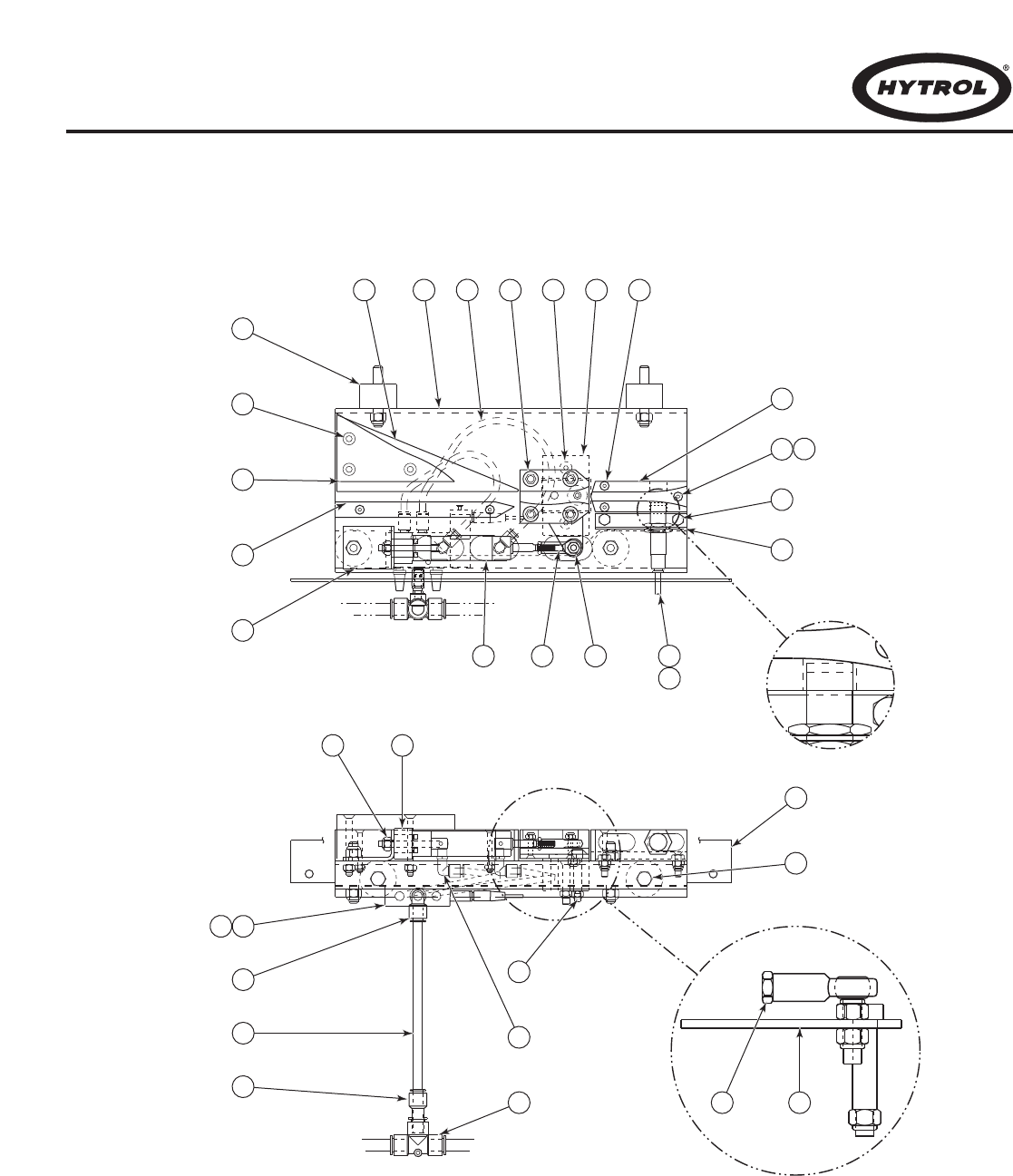
38
●
Divert Switch Assembly Parts Drawing
Dibujo del Ensamble Interruptor Desviador
35 10 2
33
13
11
3
29
28
34
31
36
12 23
7
8
16
14632
25
15
9
5
1 3027 21 18 26 17
22
19
20
24
4
39
●
Divert Switch Assembly Parts List
Lista de Partes del Interruptor Desviador
Ref. No. Part No. Description
1 — Switch Channel
— B-17048 Right Hand
— B-17047 Left Hand
2 — Switch Plate Weldment
— B-17050 Right Hand
— B-17049 Left Hand
3 — Switch Mounting Angle
— B-23596 Right Hand
— B-23595 Left Hand
4 B-23597 Cylinder Mounting Angle
5 B-23592 Proximity Switch Mounting Angle
6 019.2215 Female Rod End 1/4” Bore
7 032.21121 Cordset for Prox. Switch
8 032.2113 18mm Smart prox. Switch - DC
9 040.1005 1/4-20 x 1/2 Lg. Hex HD Bolt
10 041.198 1/4-28 NC2B Hex Jam Nut
11 041.798 3/8-16 Nylon Insert Locknut
12 041.799 5/16-18 Nylon Insert Locknut
13 041.800 1/4-20 Nylon Insert Locknut
14 041.8001 1/4-28 Nylon Insert Locknut
15 041.802 #10-24 Nylon Insert Locknut
16 042.651 #10-24x1 Lg. Hex Socket Flat HD Bolt
Ref. No. Part No. Description
17 042.6515 #10-24x1-3/4 Lg. Socket Flat HD Bolt
18 042.6535 1/4-20x3/4 Lg. Hex Socket Flat HD Bolt
19 042.6545 1/4-20x2-1/2 Lg. hex Socket Flat HD Bolt
20 090.2655 Upper Switch Block
21 — Switch
— 090.2665 Right Hand
— 090.2675 Left Hand
22 092.163 Rubber Vibration Mount 1-1/2” O.D.
23 092.1635 Rubber Vibration Mount 1-1/4” O.D.
24 092.1775 Straight Guide
25 092.1825 Switch Guide
26 092.1835 Switch Bearing
27 092.1845 Lower Switch Block
28 094.10795 Valve, 4-Way Single Solenoid, 24 VDC
29 094.10796 Pico Connector Cable for 4-Way Valve
30 094.11481 1/4” O.D. Polyurethane Tubing
31 094.1149 3/8” O.D. Polythurethane Tubing
32 094.12021 Air Cylinder
33 094.1406 90° Swivel Elbow 1/8 NPT to PLST
34 094.14083 Elbow 3/8” Male to Female
35 094.14089 Tee 1/2” PLST to 1/2” PLST
36 094.1465 Reducer 3/8” to Push-In
See Page 31 for Information on How To Order Replacement Parts
Recommended Spare Parts Highlighted in Gray
Vea la Página 31 para información sobre como ordenar partes de repuesto
Las Partes de Repuesto Recomendadas se Resaltan en Gris
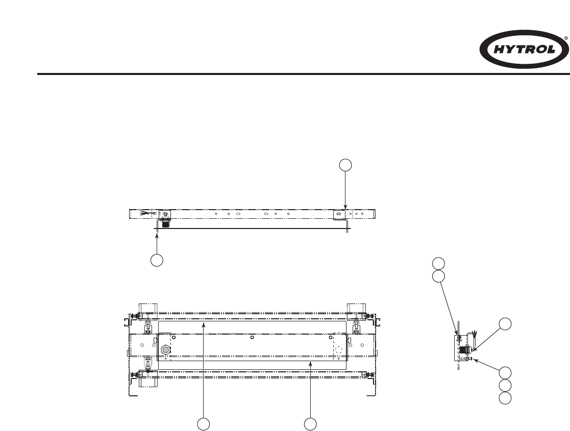
40
3
2 1
4
10
5
6
7
8
9
●
Safety Switch Assembly Parts Drawing
Dibujo del Ensamble de Interruptor de Seguridad
41
Ref. No. Part No. Description
1 B-23792 Switch Sensor Plate (Specify OAW)
2 — Switch Sensor Belt
— 069.715 26 in. OAW
— 069.7151 30 in. OAW
— 069.7152 32 in. OAW
— 069.7153 36 in. OAW
— 069.7154 38 in. OAW
— 069.7155 42 in. OAW
— 069.7156 44 in. OAW
Ref. No. Part No. Description
— 069.7157 48 in. OAW
3 B-23793-L Mounting Bracket LH
4 B-23793-R Mounting Bracket RH
5 032.211 Proximity Switch
6 041.100 1/4-20 Hex Nut
7 042.3027 1/4-20 x 1-3/4 in. Lg. Truss Head Bolt
8 090.220 Plastisol Cap
9 042.300 1/4-20 x 1/2 in. Lg. Truss Head Bolt
10 049.527 1/4-20 Lock Nut
See Page 31 for Information on How To Order Replacement Parts
Recommended Spare Parts Highlighted in Gray
Vea la Página 31 para información sobre como ordenar partes de repuesto
Las Partes de Repuesto Recomendadas se Resaltan en Gris
●
Safety Switch Assembly Parts List
Lista de Partes del Interruptor de Seguridad

42
●
Notes

HYTROL CONVEYOR COMPANY, INC.
2020 Hytrol Drive
Jonesboro, Arkansas 72401
Phone: (870) 935-3700
EFFECTIVE AUGUST, 2000
Printed in the USA 2/00
www.hytrol.com
