Hyundai Electronics Co HD-MIC1900 User Manual cover
Hyundai Electronics Industries Co Ltd cover
UserManual.wiki
>
Hyundai Electronics Co
>
HD MIC1900 User Manual
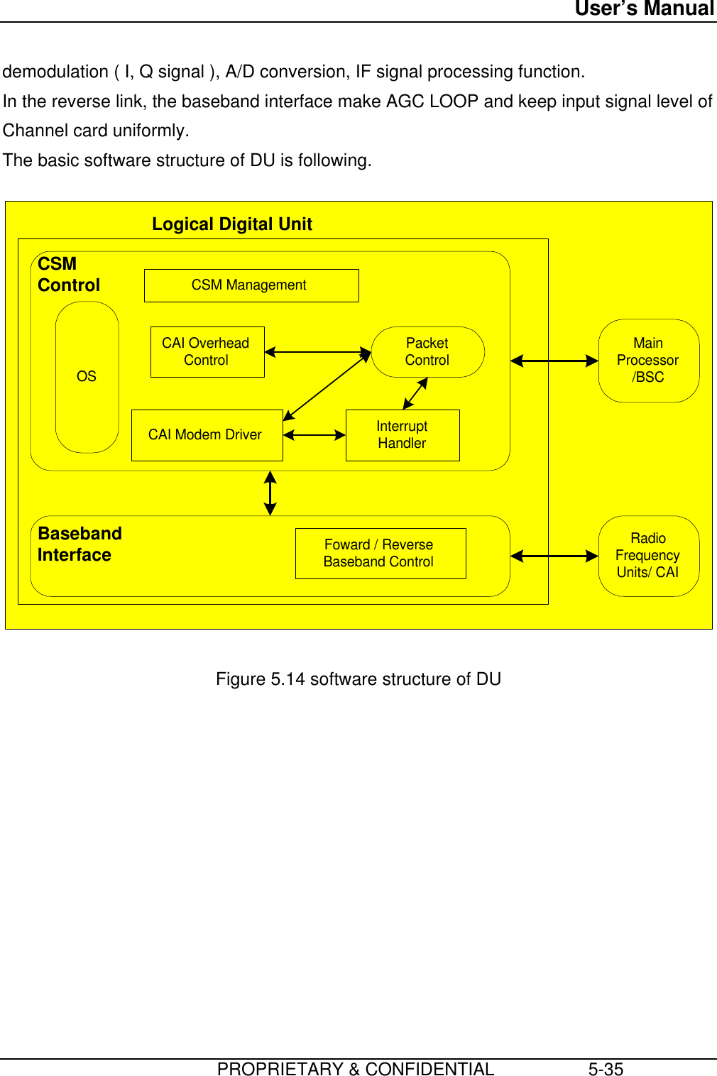
Users Manual
Navigation menu
Upload a User Manual
Namespaces
Wiki Guide
HTML
PDF
Info
Views
User Manual
Discussion / Help
Navigation
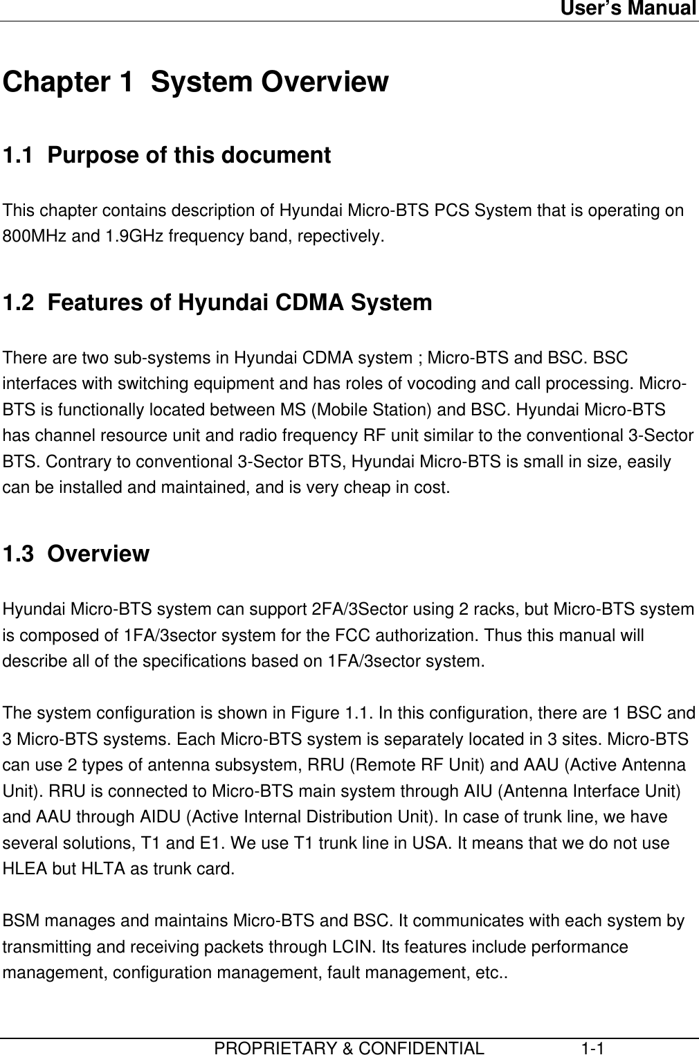
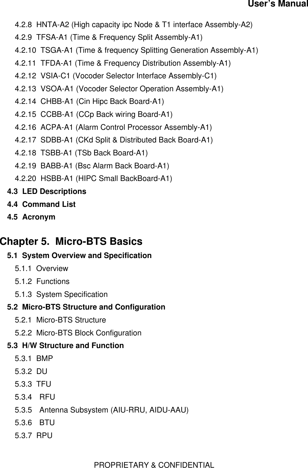
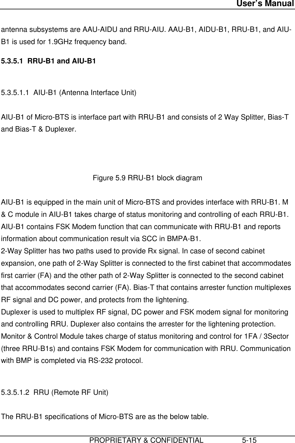
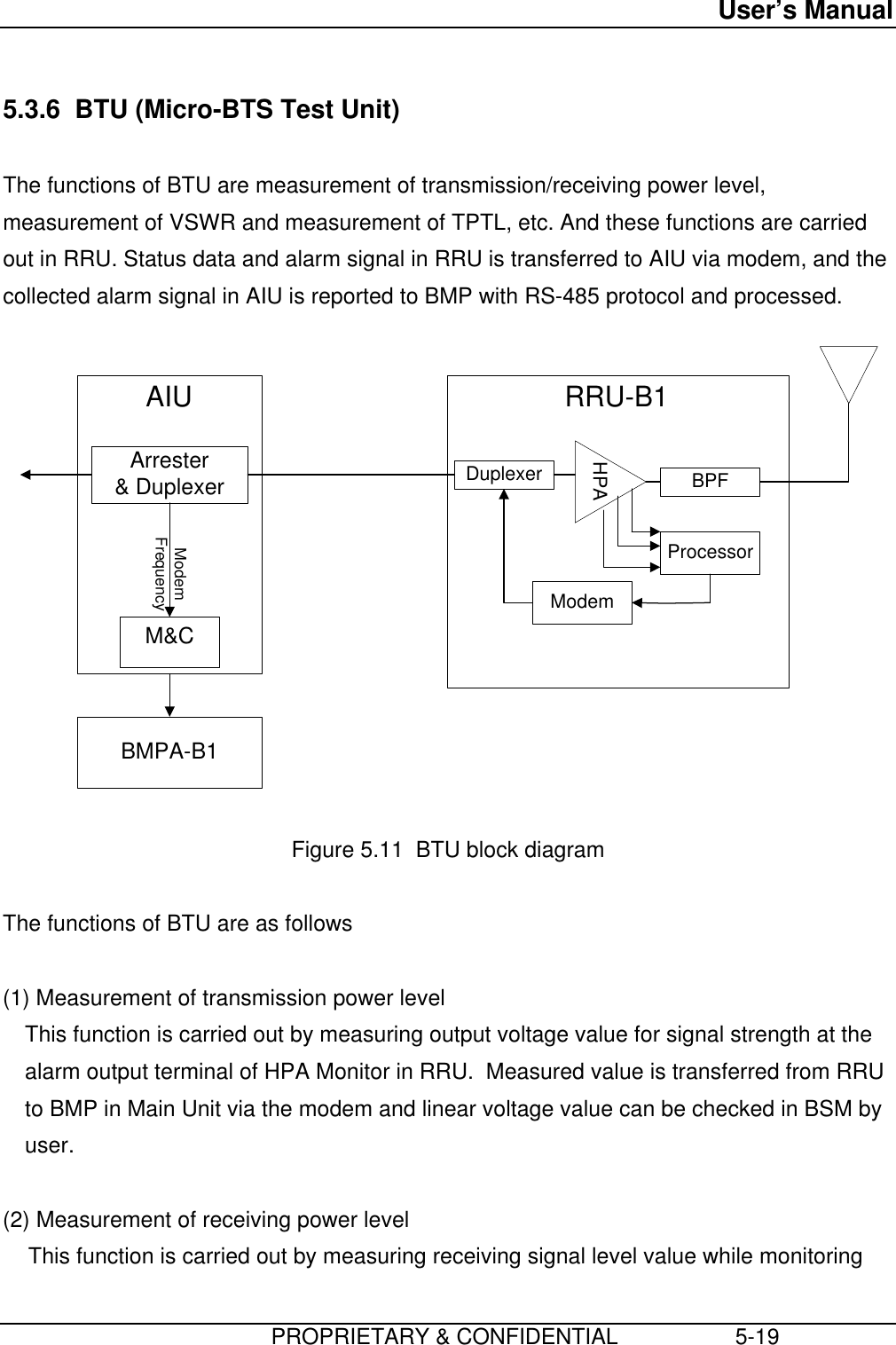
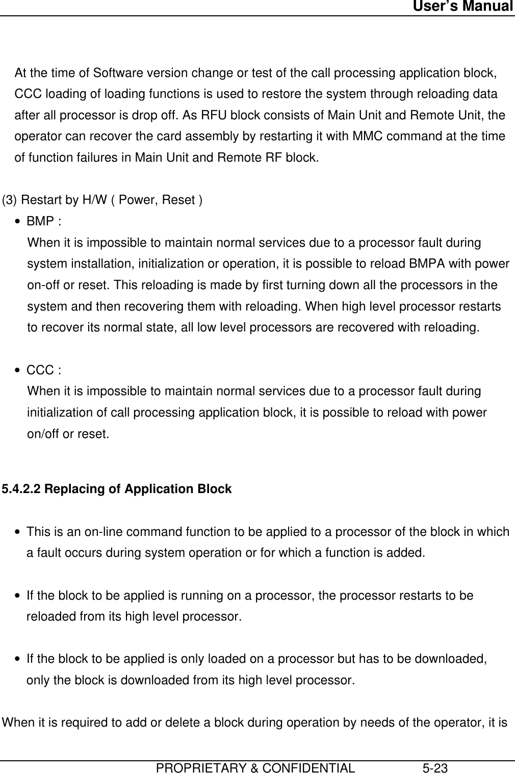
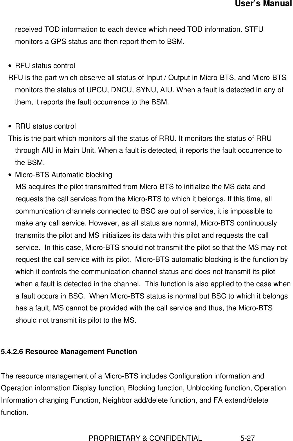
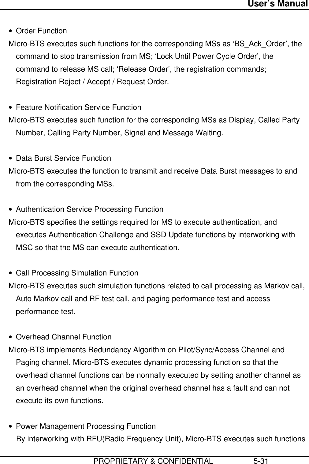
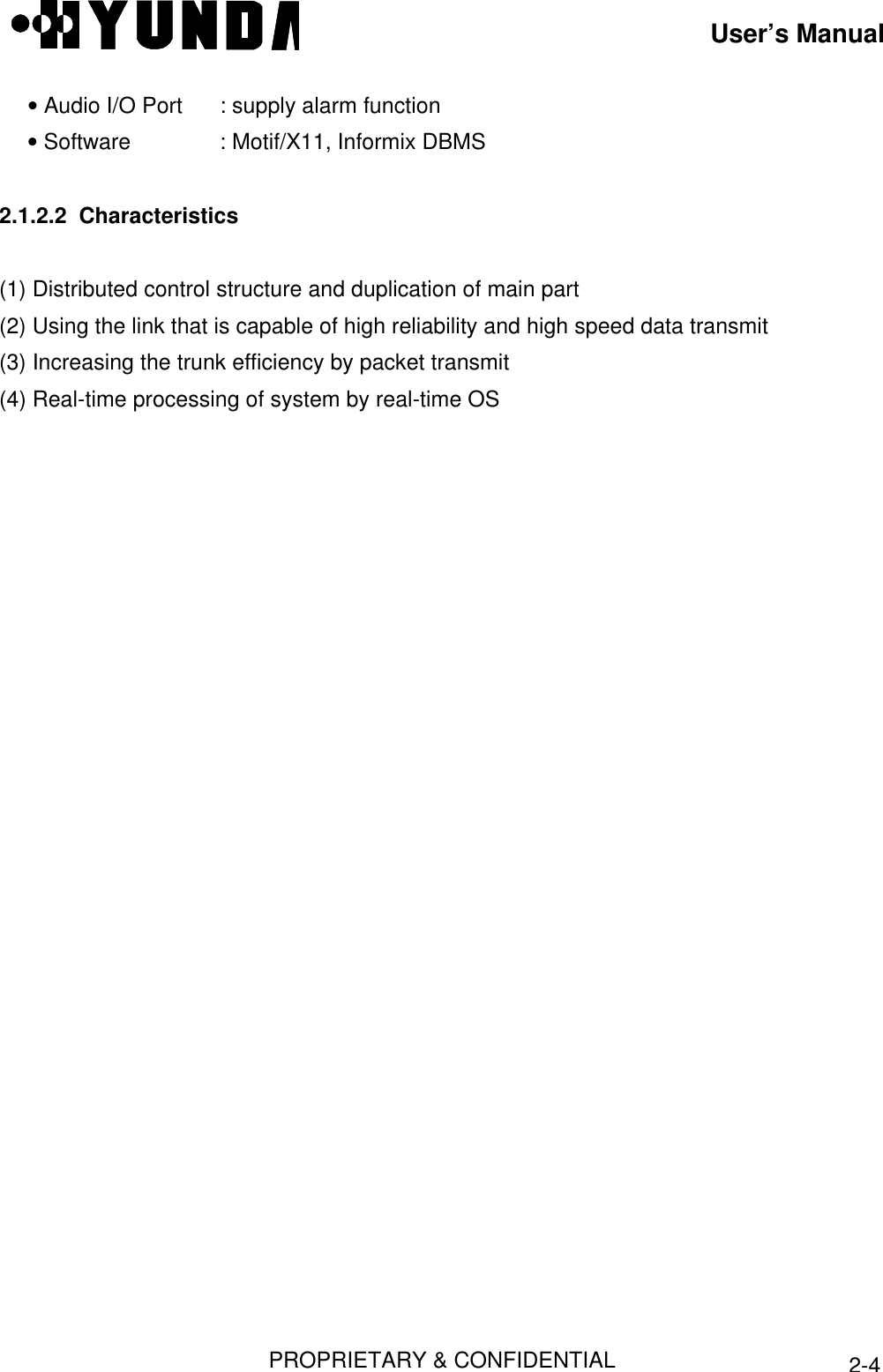
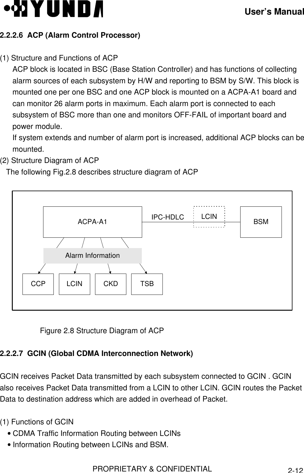
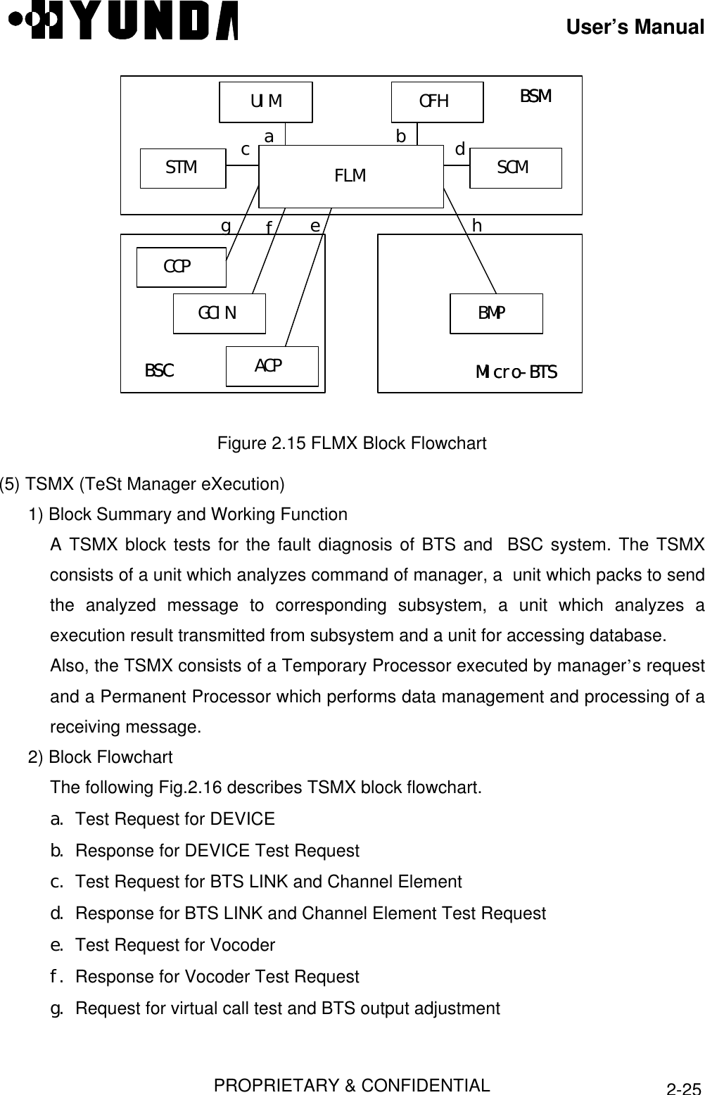
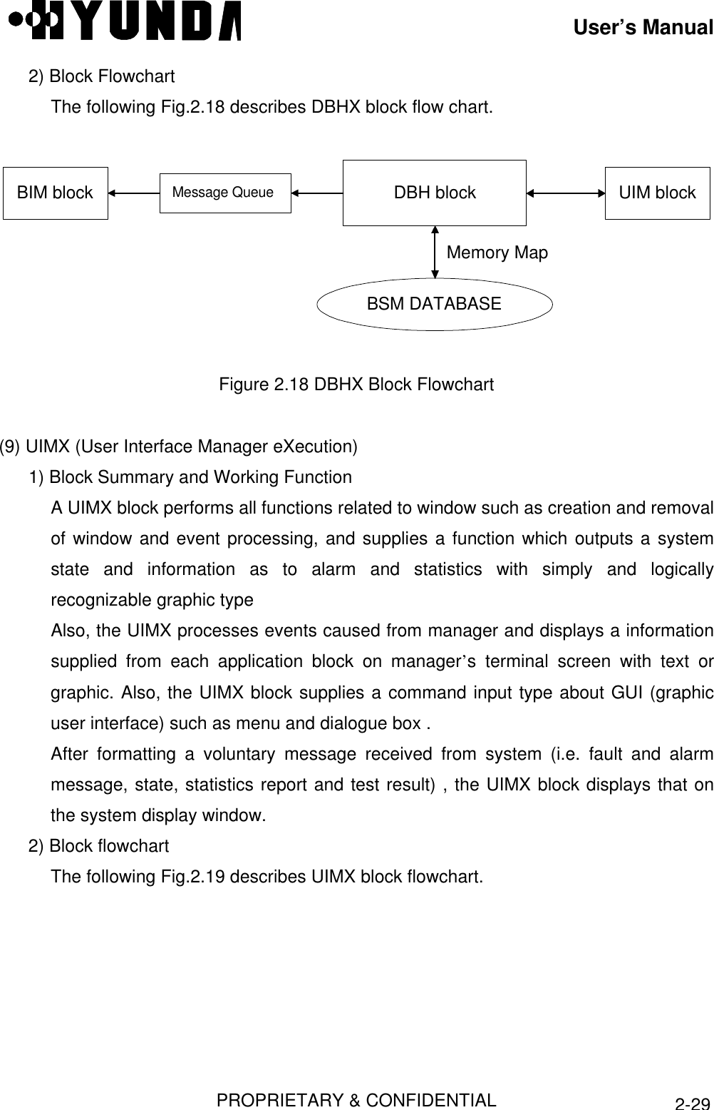
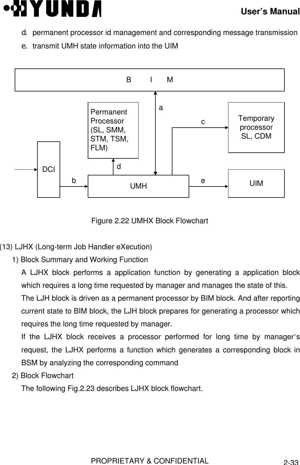
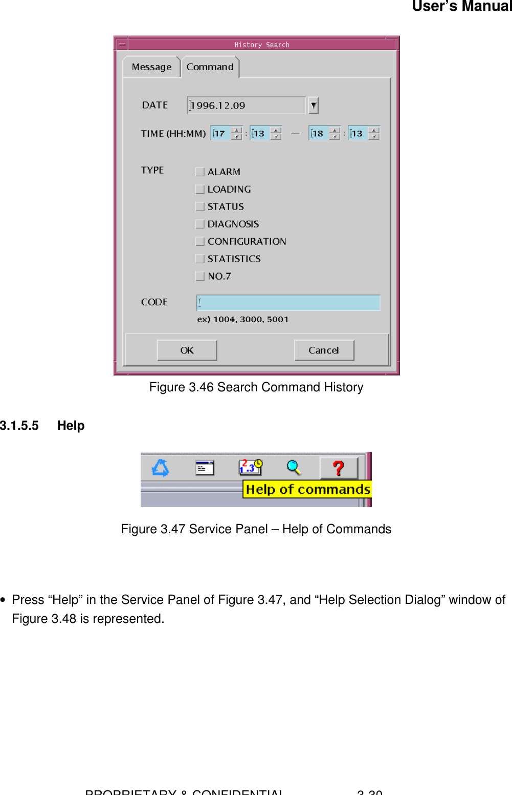
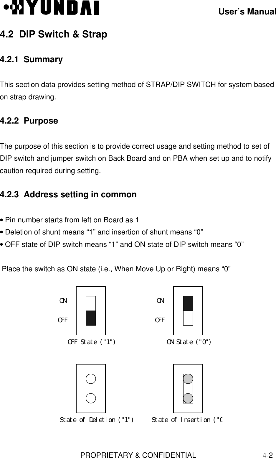
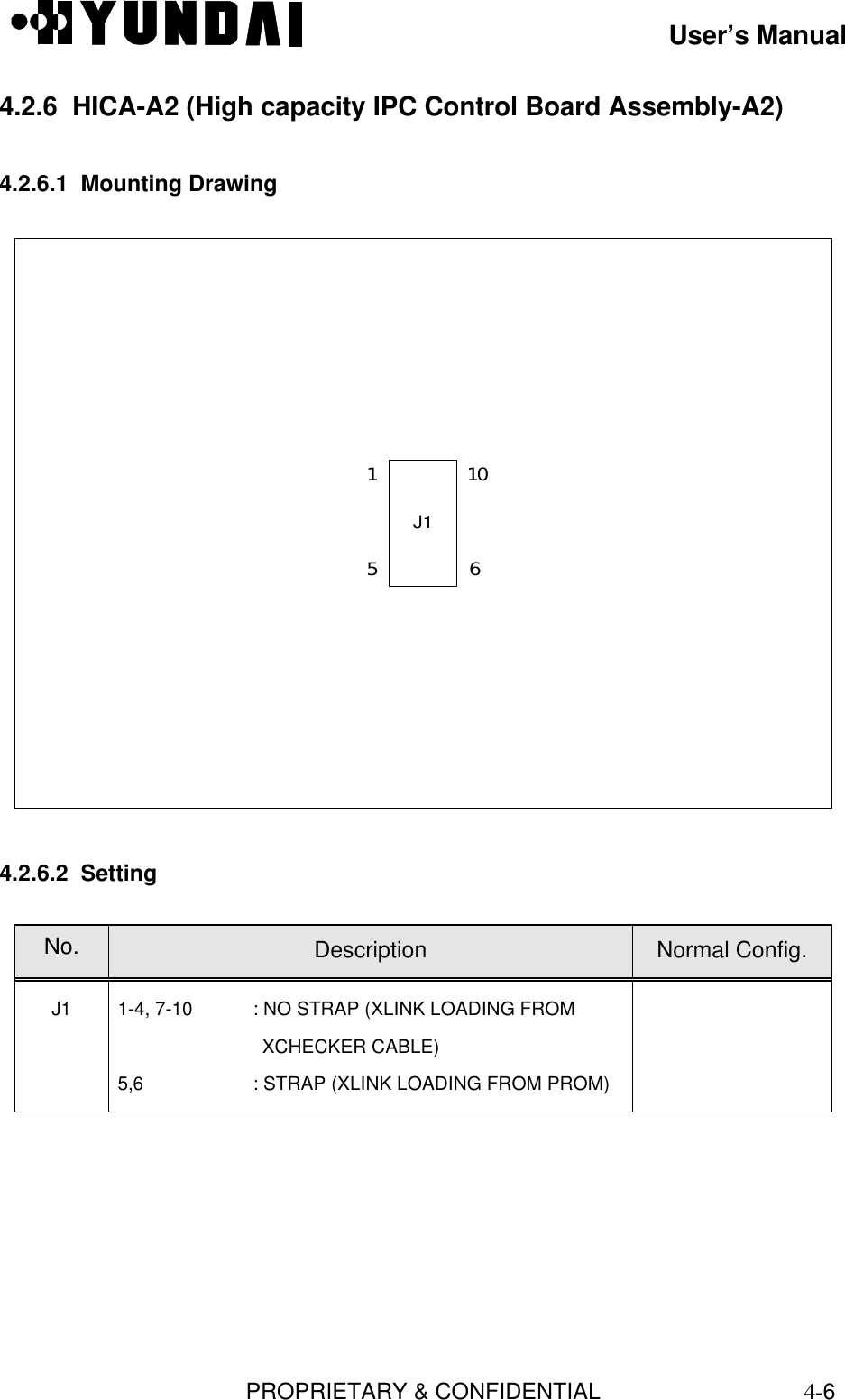
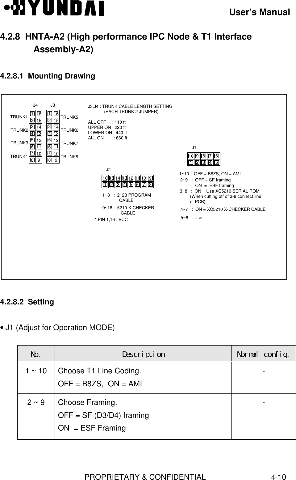
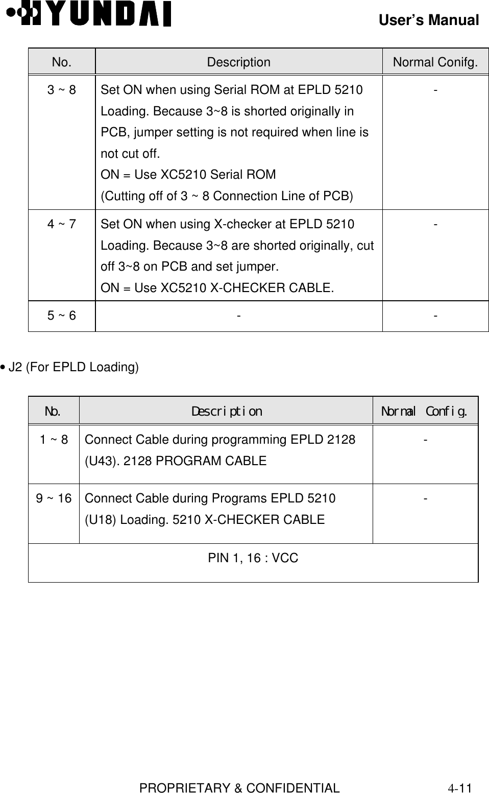
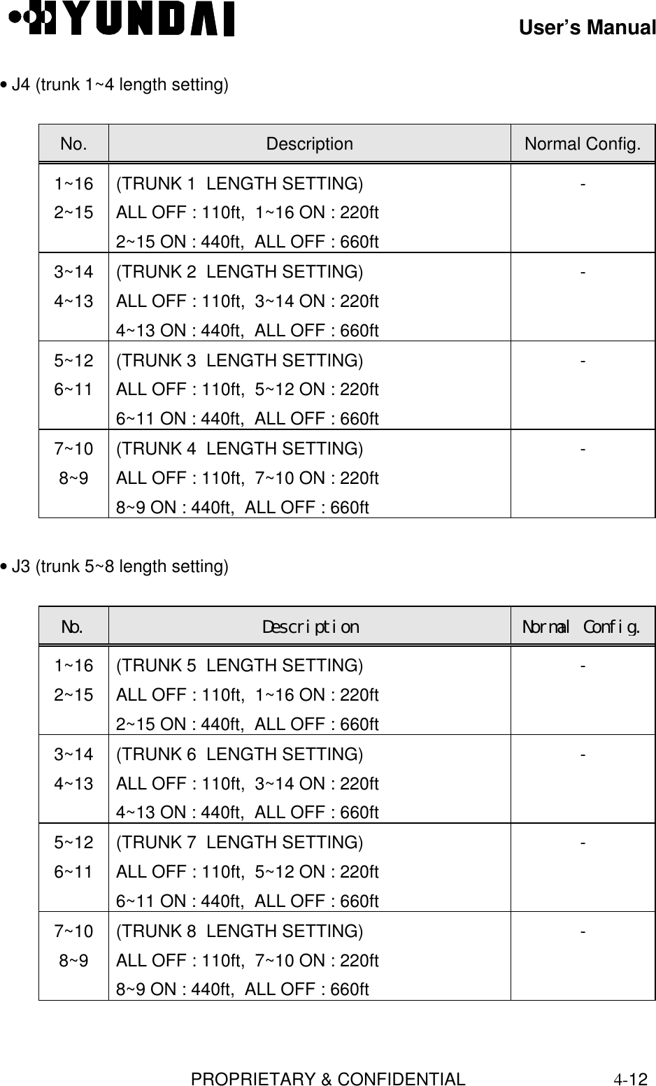
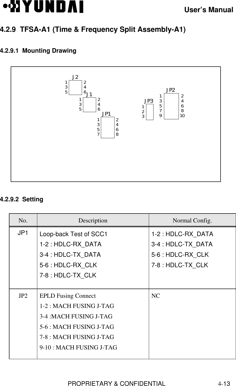
![User’s ManualPROPRIETARY & CONFIDENTIAL2-1Chapter 2 BSC Basics2.1 System Overview and Specification2.1.1 OverviewBSC is located between MSC and BTS. It carries out a wire/wireless link control function,handoff function and transcoding function. And it is made up of a LCIN, GCIN, TSB, CCP,CSB, CKD, BSC-GPS, and BSM block. [Refer to Fig.2.1].BTS0BTS1BTS59LCINCCP CSBTSBACP CKDBTS BSC MSCBSM Others BSCT1T1T1T1T1IPC IPC IPC IPCIPCIPCIPCGCINIPCBSC-GPSFigure 2.1 Configuration of BSCEach block does following functions.• BSM is a system used to operate the entire BSC and BTS, to manage their resources,status and configuration, and to execute the user interface, and maintenance. It consistsof a SUN Sparc Workstation and the various types of input/output devices for enhancinguser's convenience.• LCIN is a network that provides the communication paths of packet-type data betweensubsystems. LCIN routes and transmits packet data within BSC and it has trunk interfacefunction between BSC and BTS.](https://usermanual.wiki/Hyundai-Electronics-Co/HD-MIC1900/User-Guide-48794-Page-8.png)
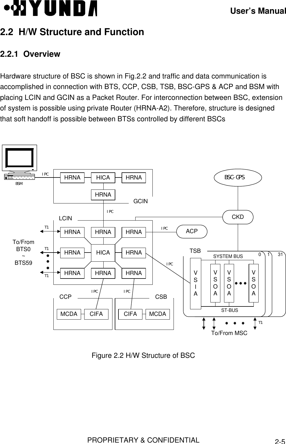
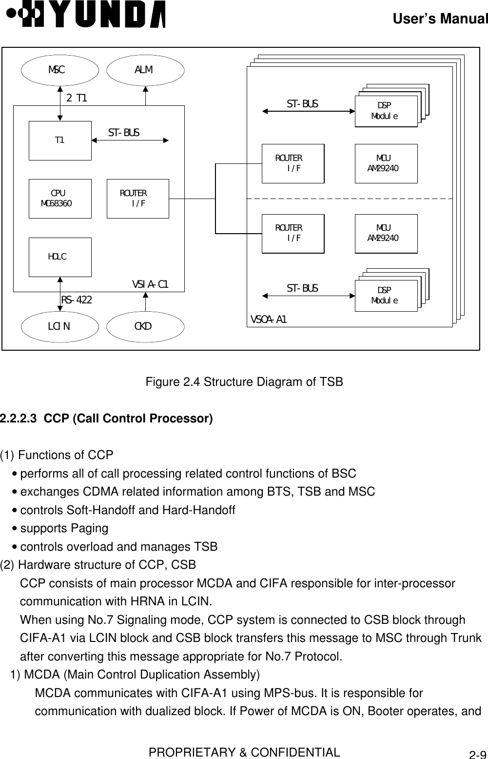
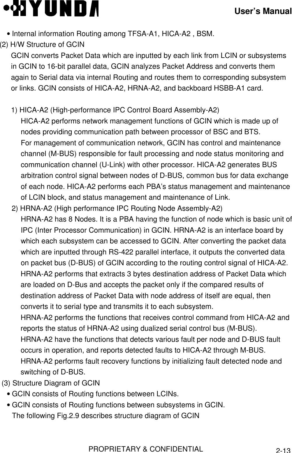
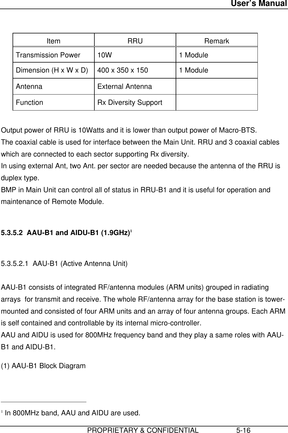
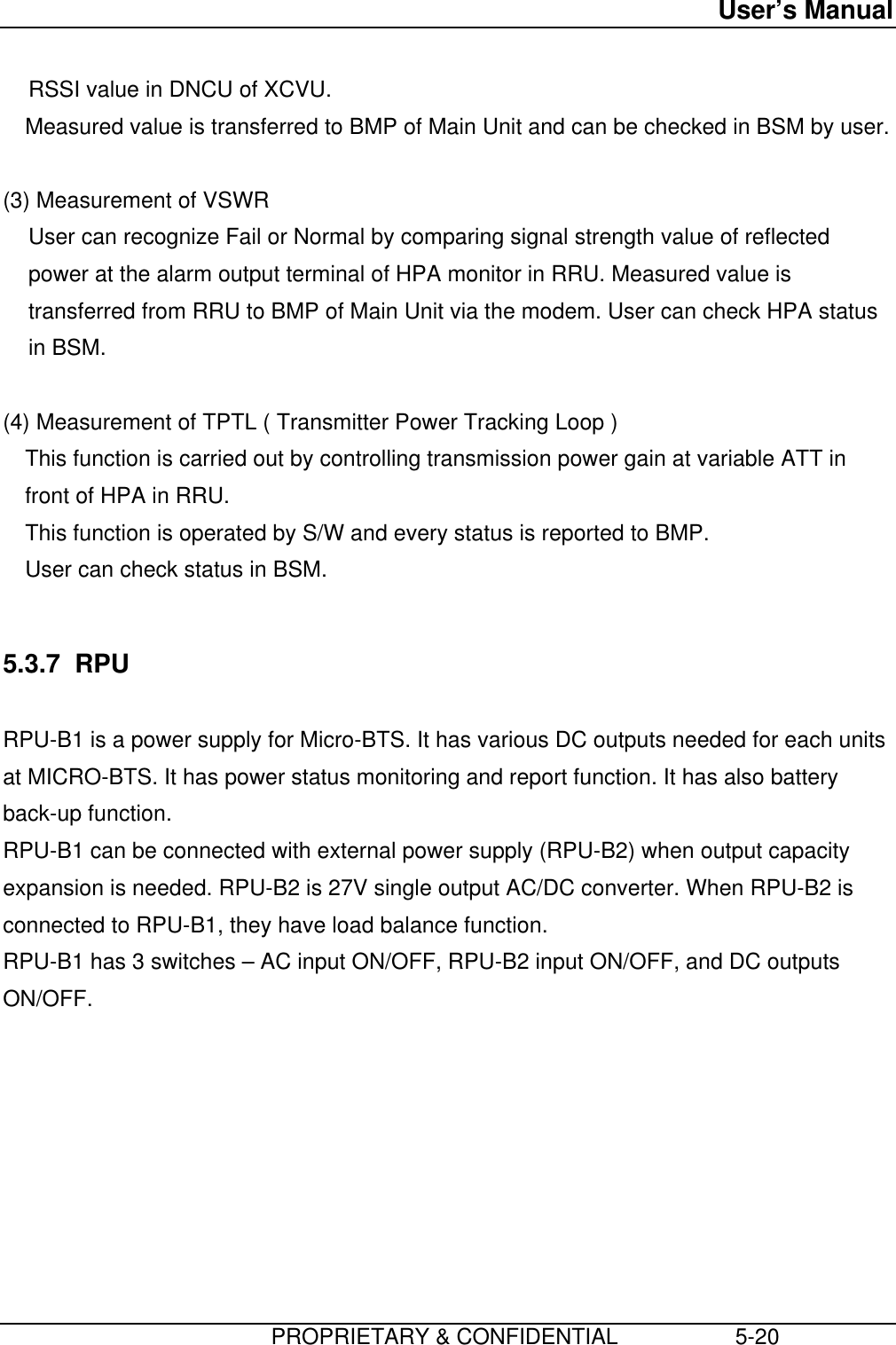
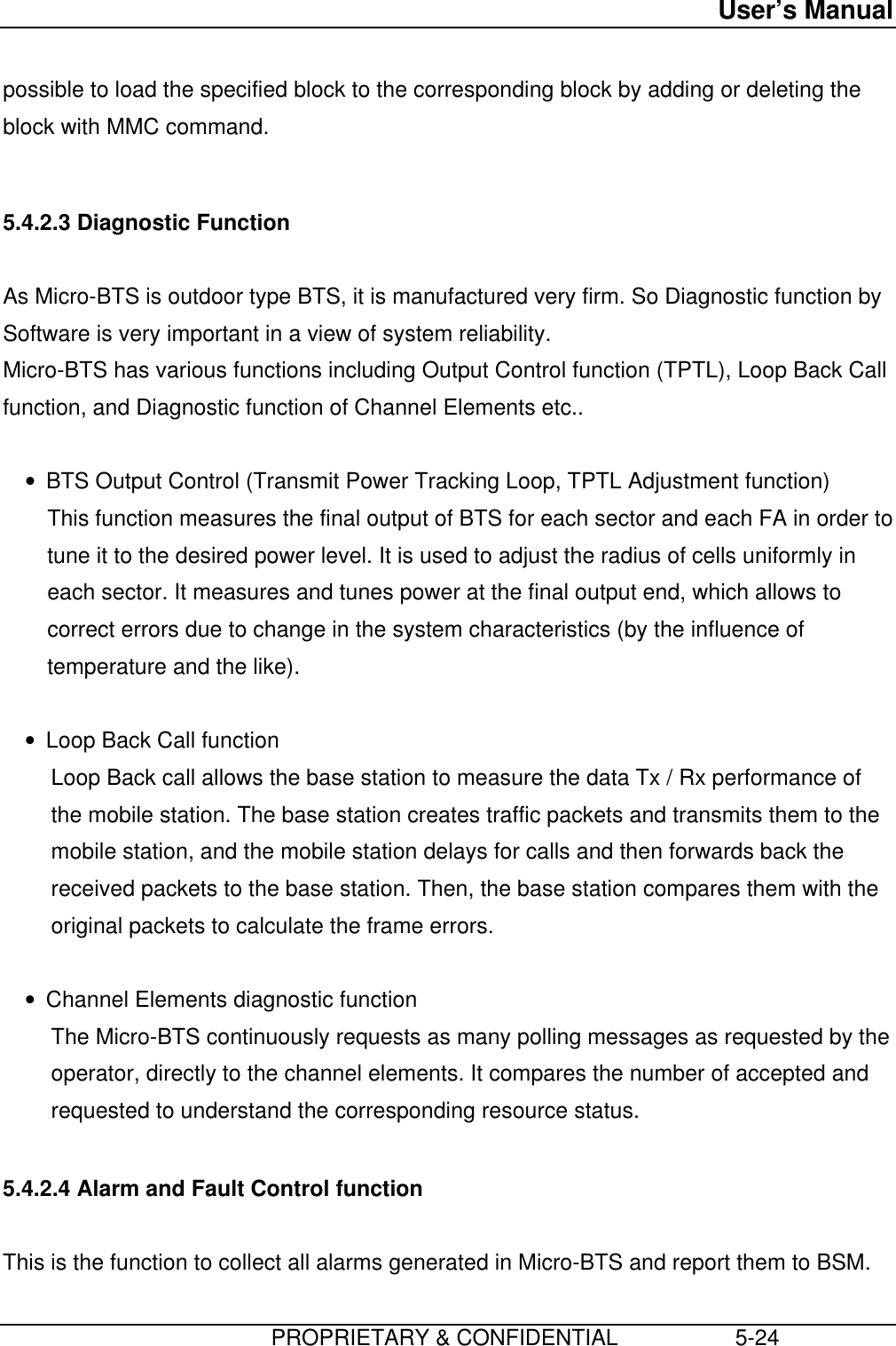
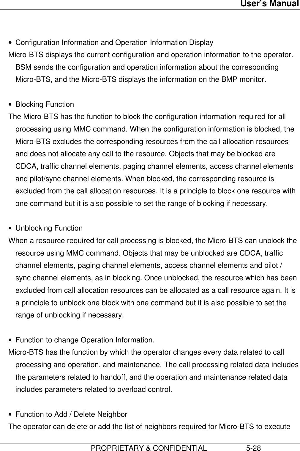
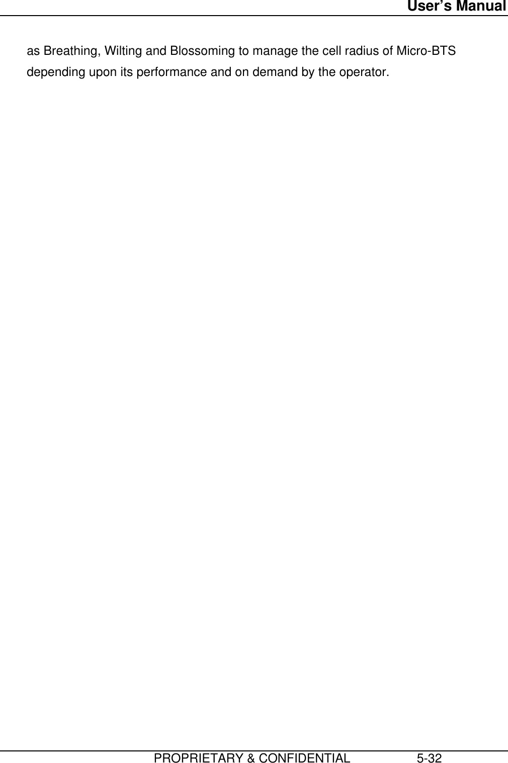
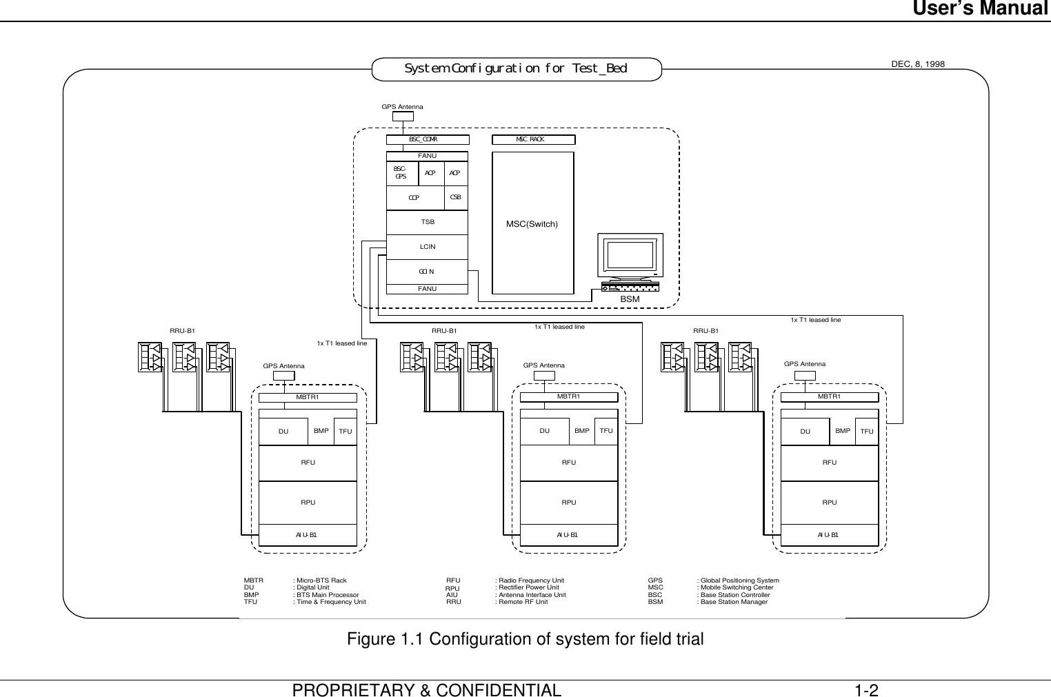
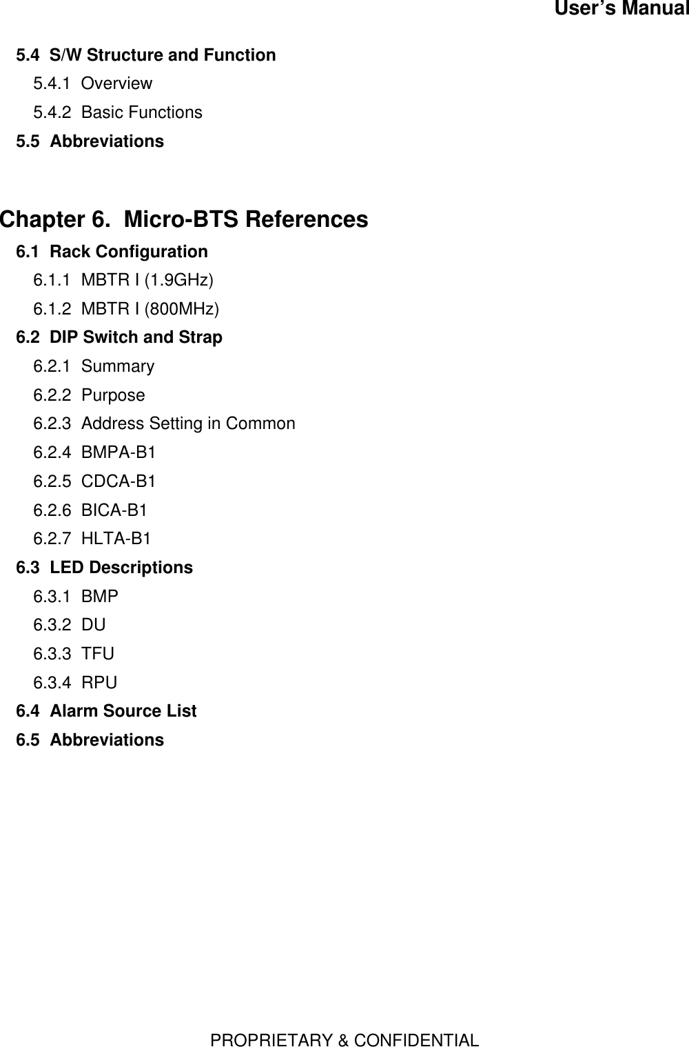
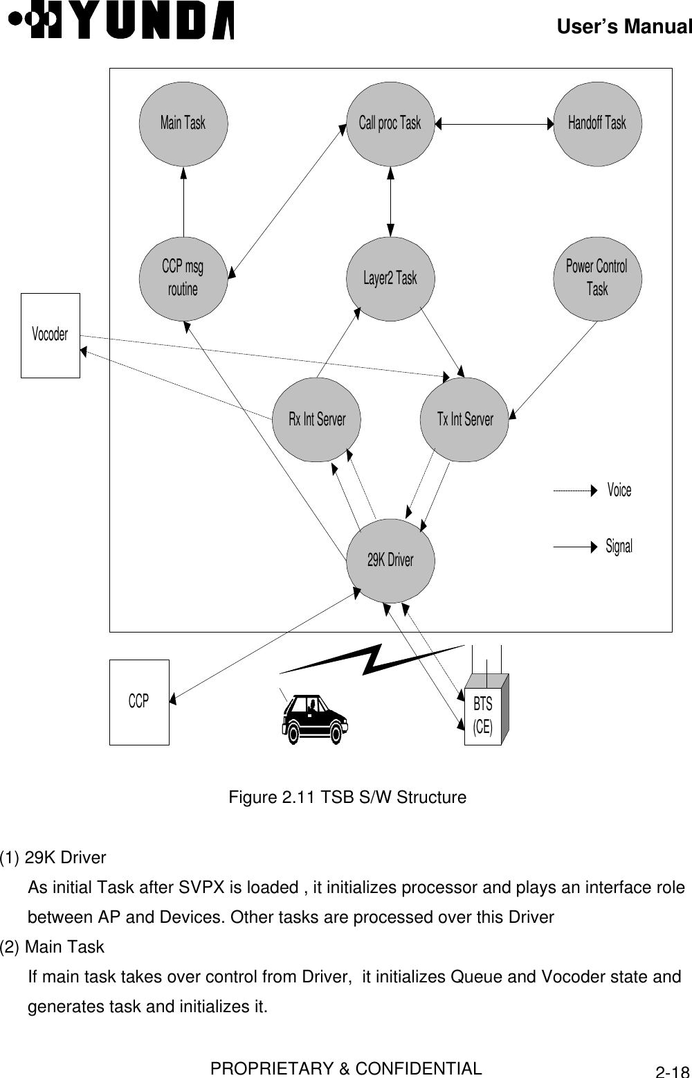
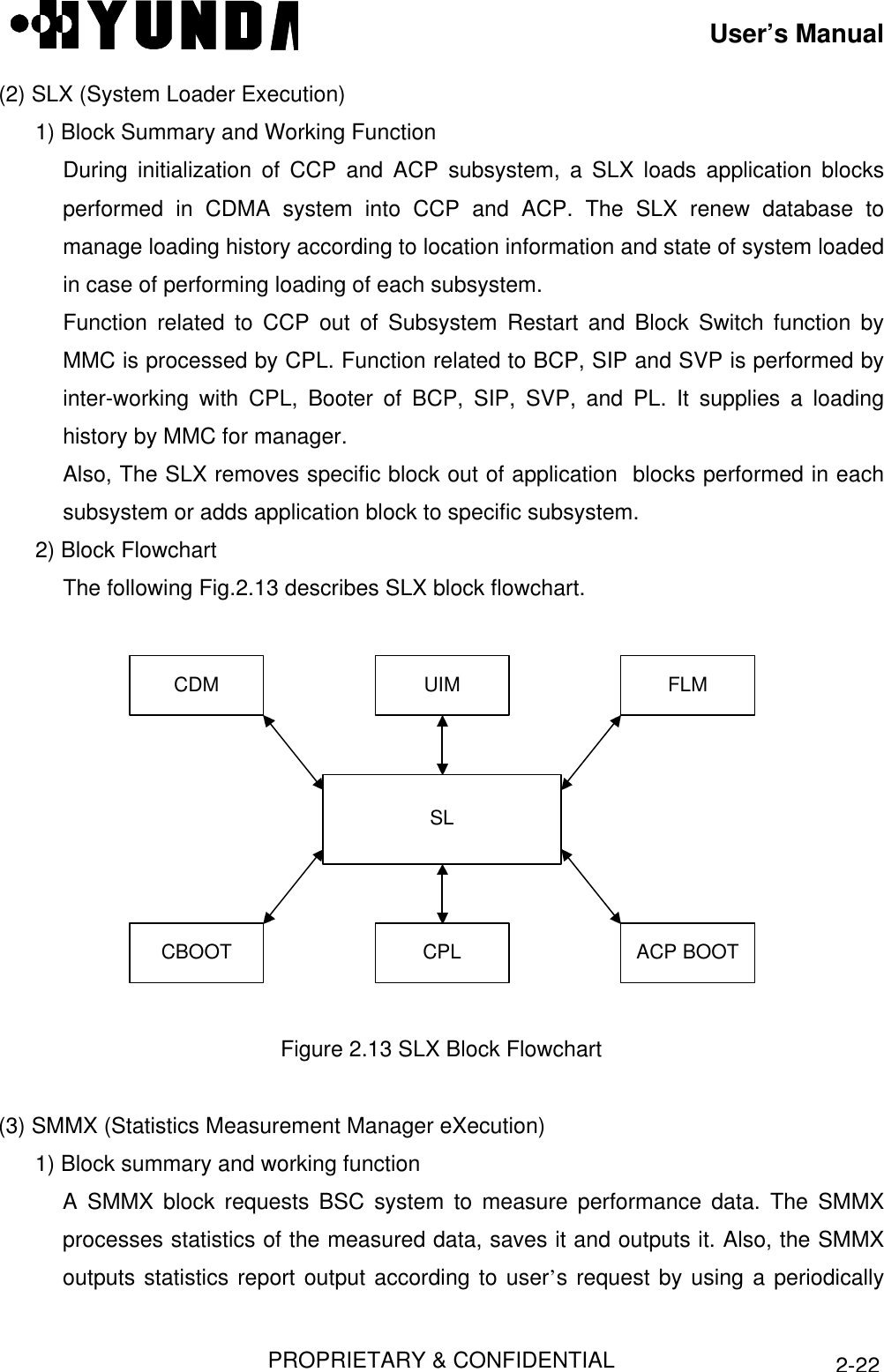
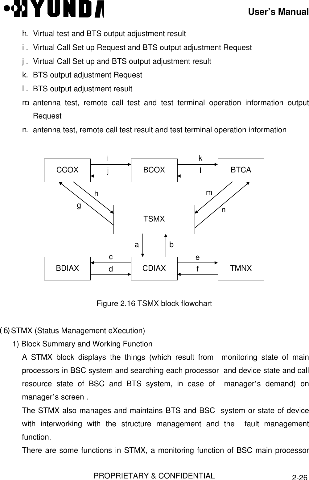
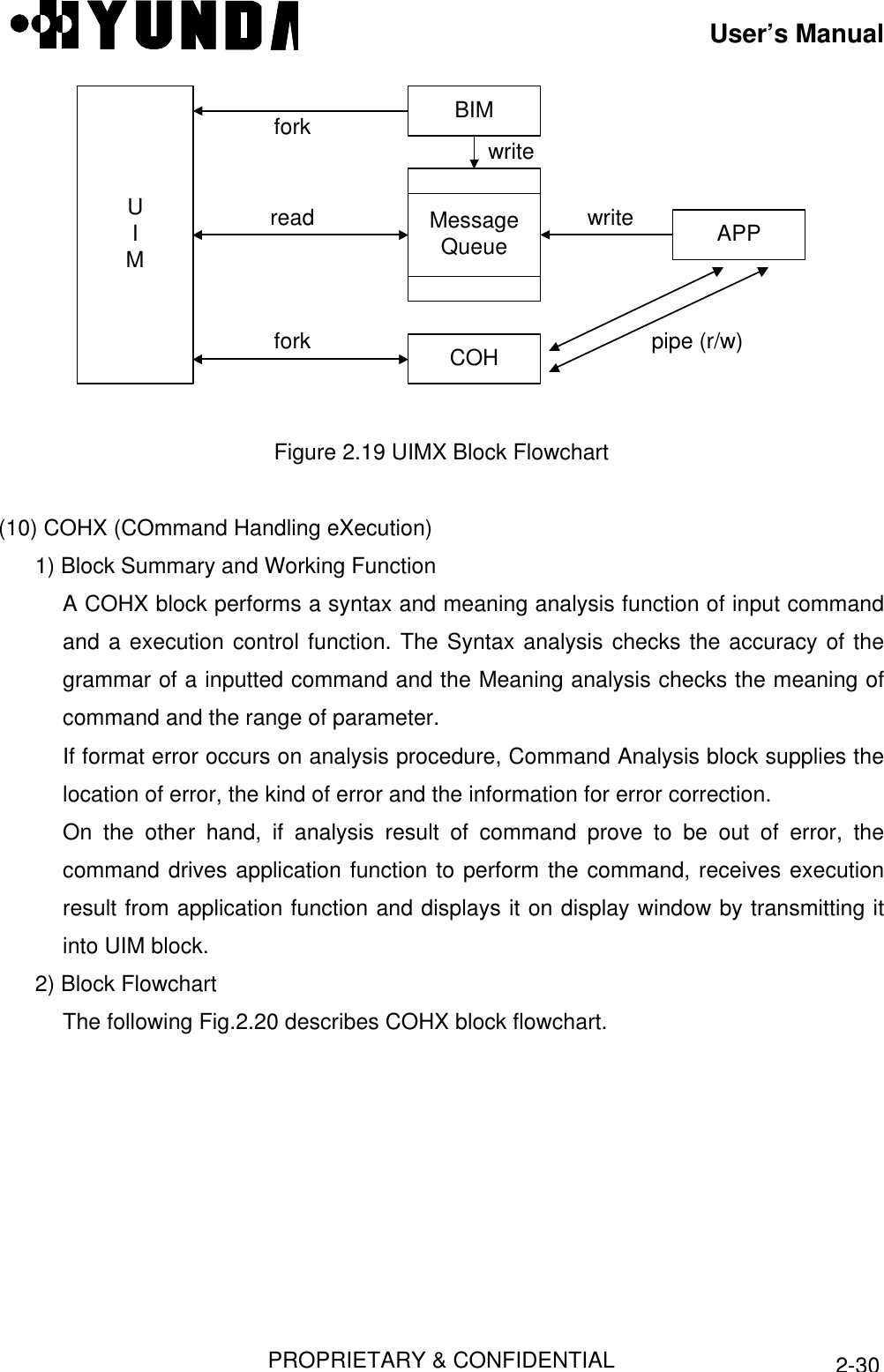
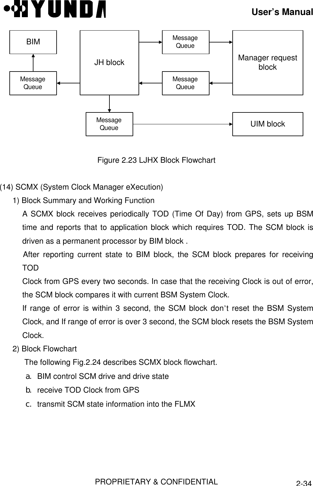
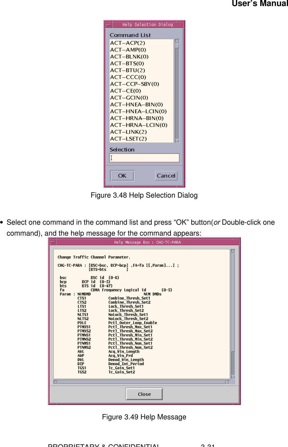
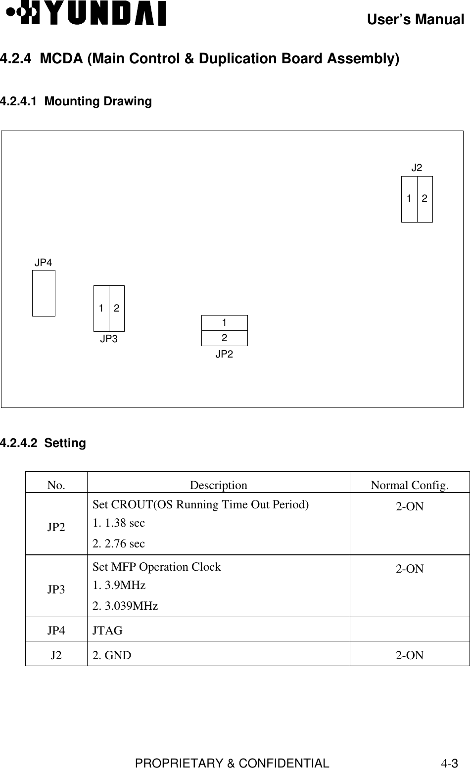
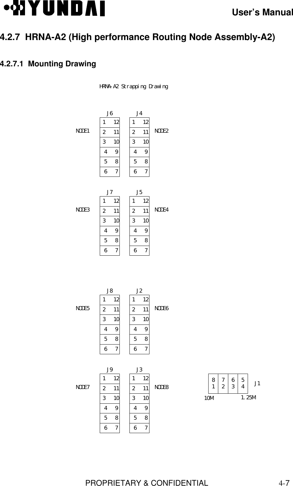
![User’s ManualPROPRIETARY & CONFIDENTIAL2-17• Start and Restart of process• Stand-by Loading• initialization (data initialization, process initialization and state identification)2.3.2.2 Software Structure of CCPThe following Fig.2.10 describes S/W structure of CCPCCOX CRMXCDAXCSHXCDIAXCMMXCPLXCRAXPLDFigure 2.10 S/W Structure of CCP2.3.2.3 TSB S/W StructureTSB S/W (from now on, SVPX) is the S/W block driven over VSOA board, since twoProcessors exist in one board, each Processor process six channels. SVPX processestraffics and signals coming from Mobile, CE and CCP. SVPX consists of following Tasks.[Refer to Fig.2.11]](https://usermanual.wiki/Hyundai-Electronics-Co/HD-MIC1900/User-Guide-48794-Page-24.png)
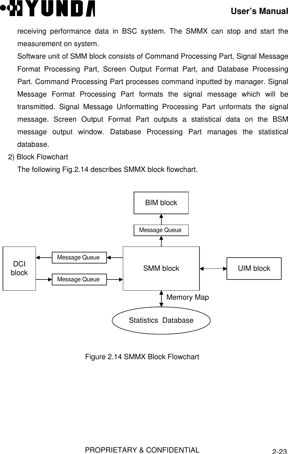
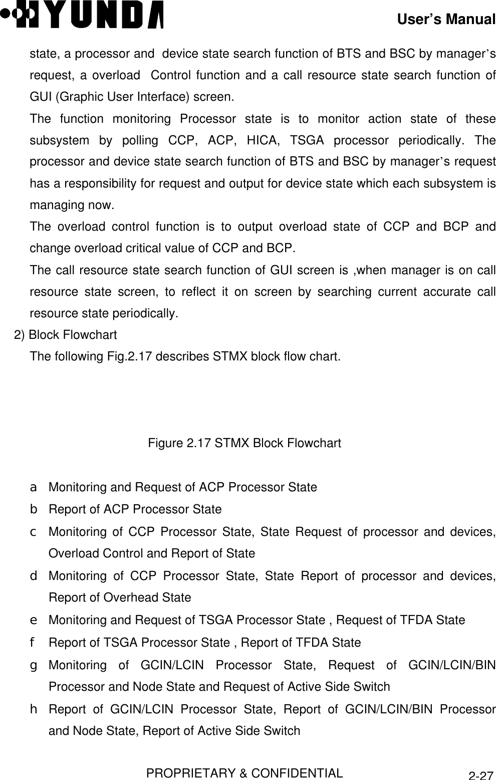
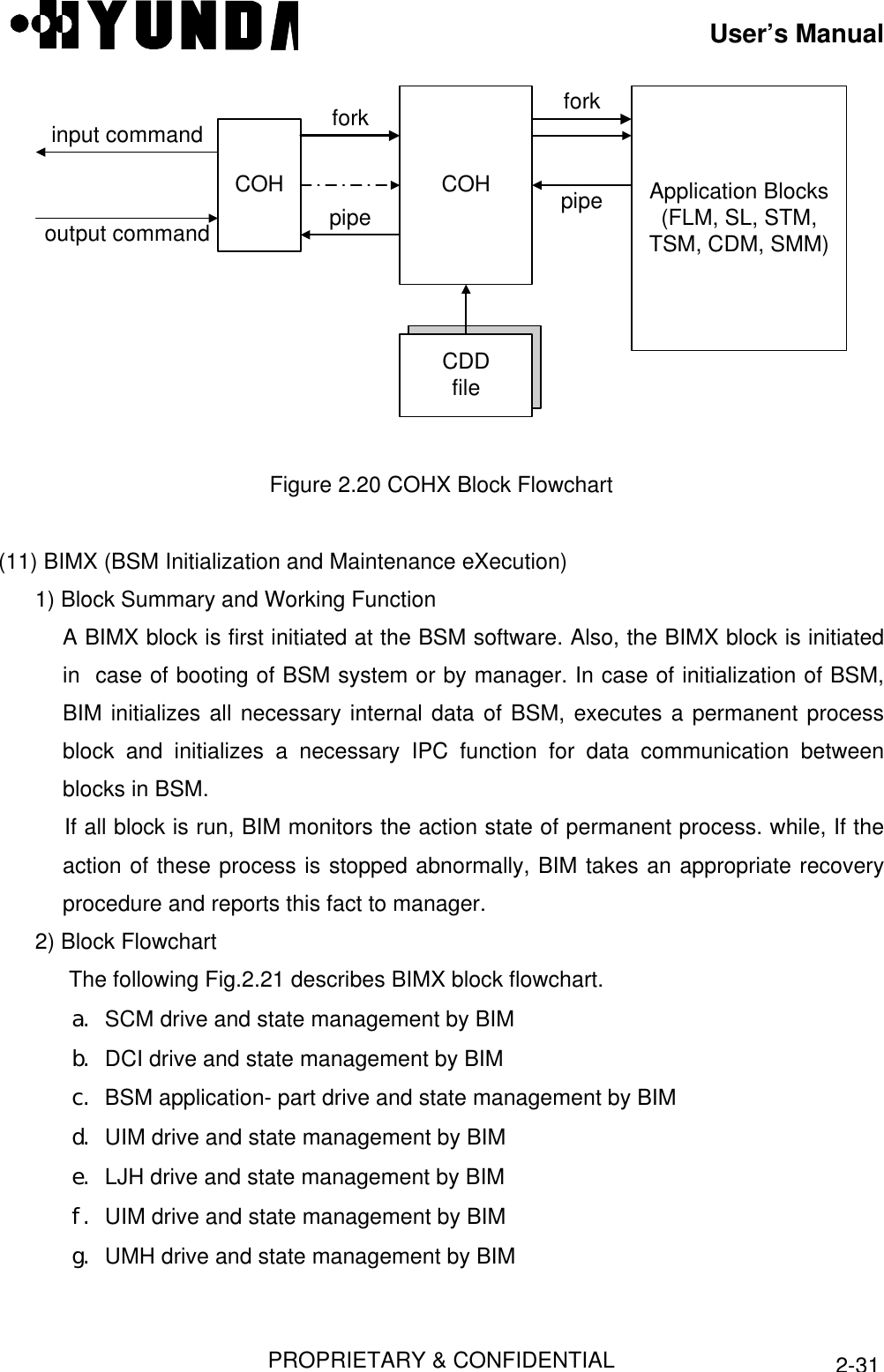
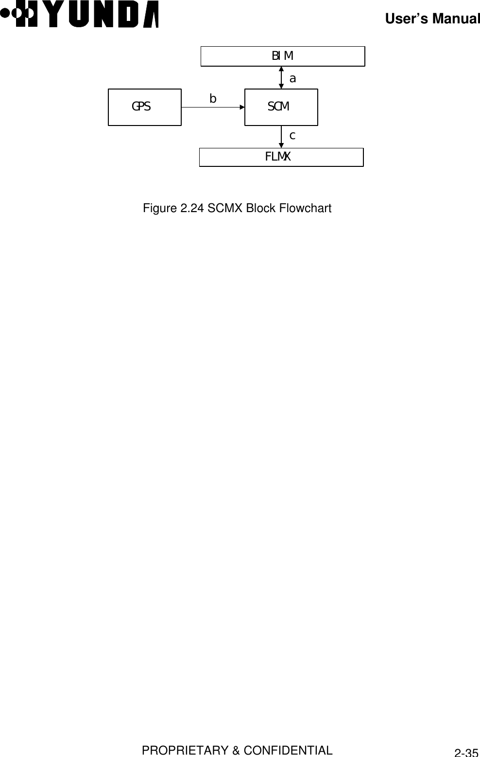

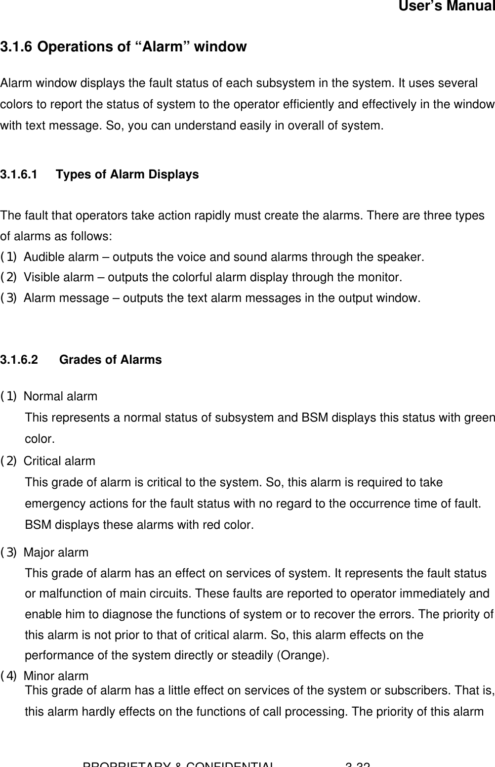
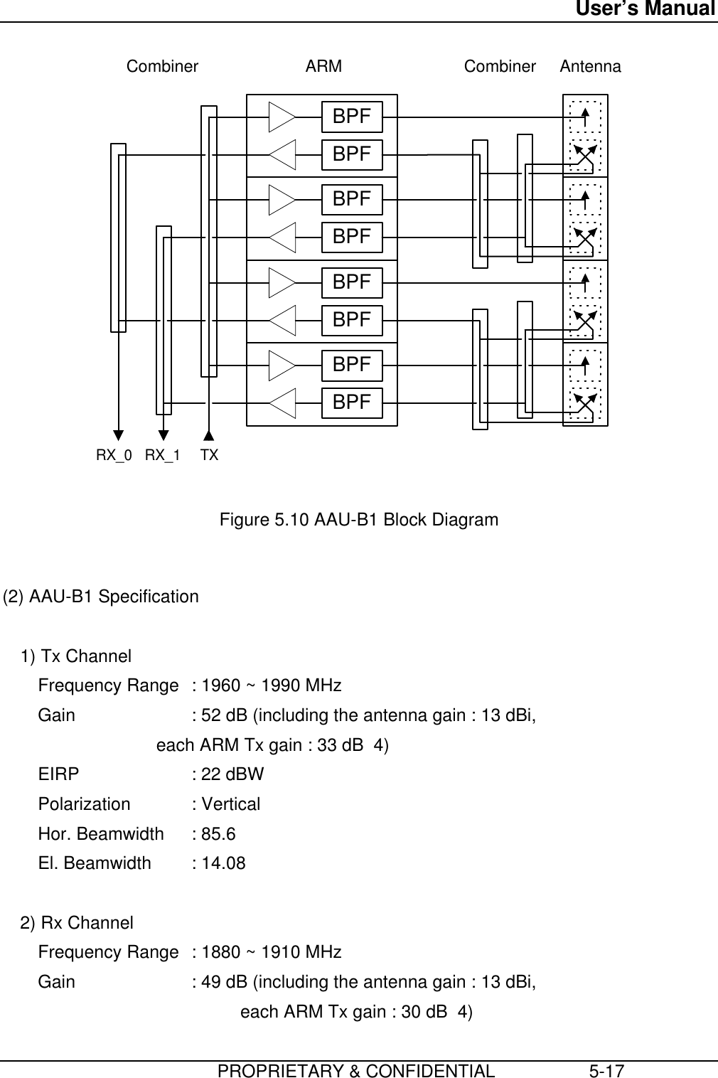
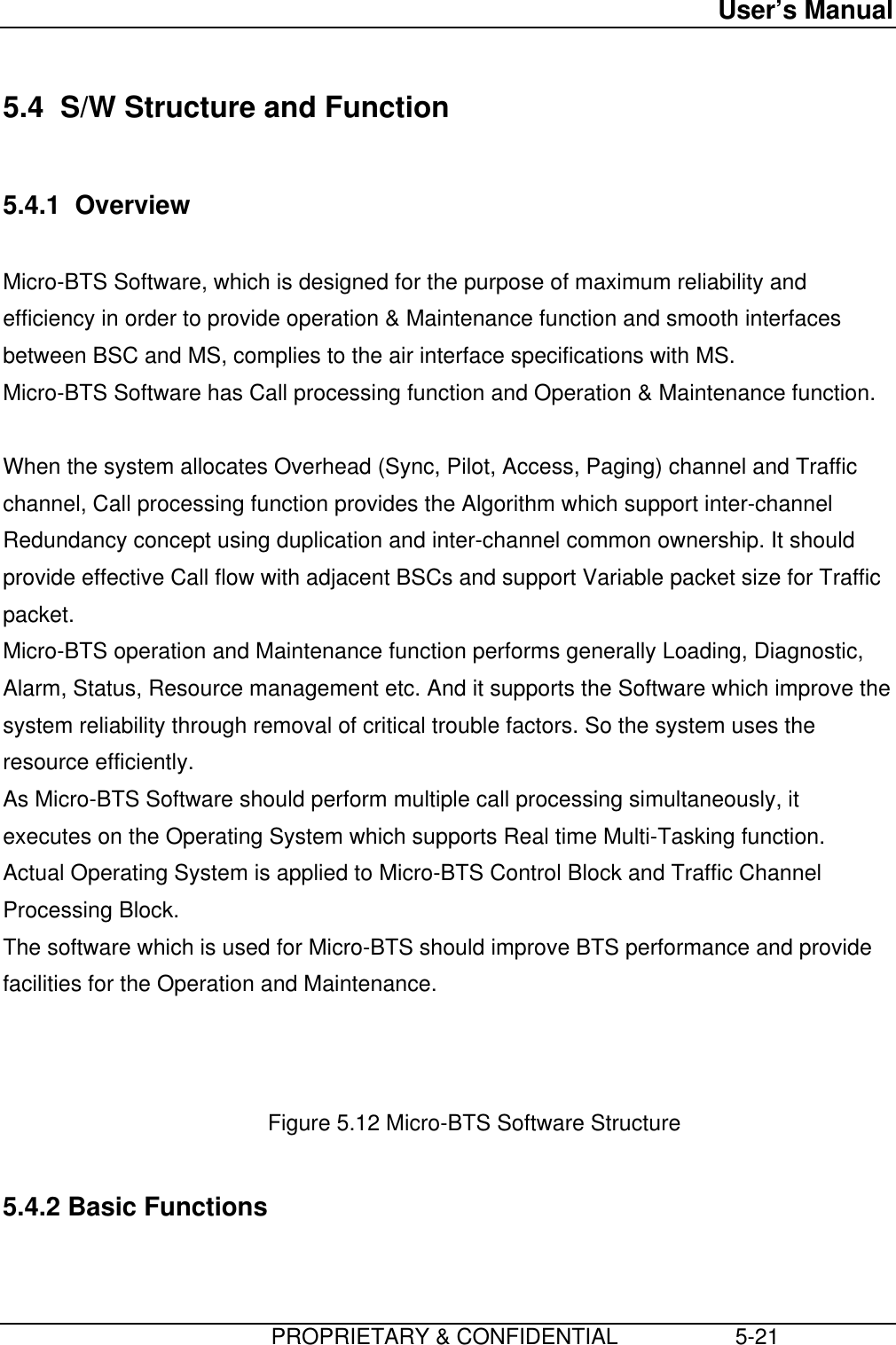
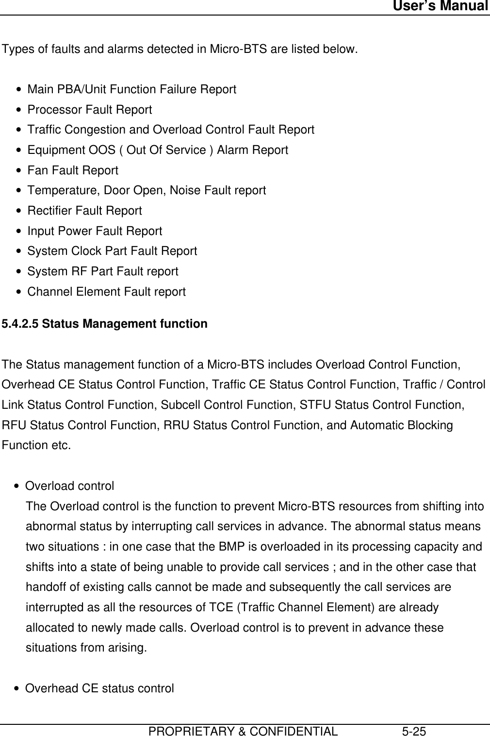
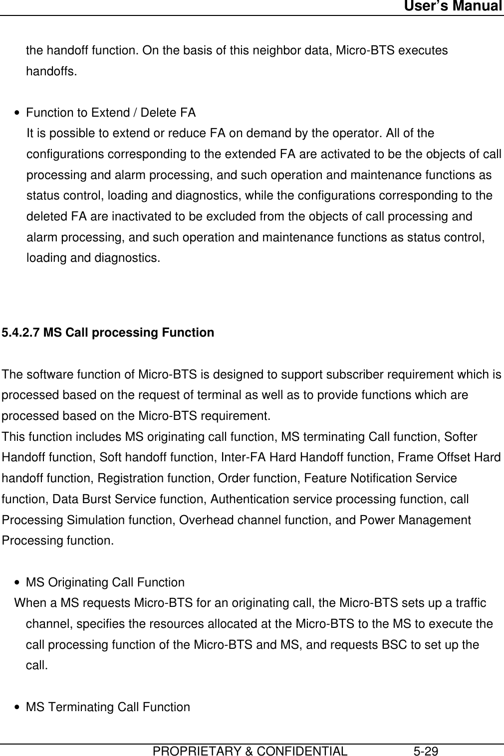
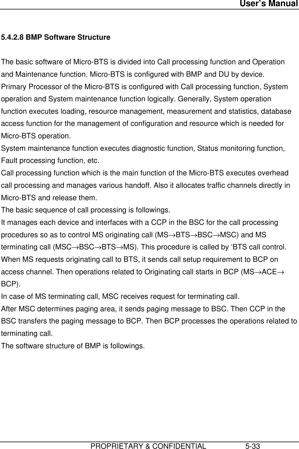
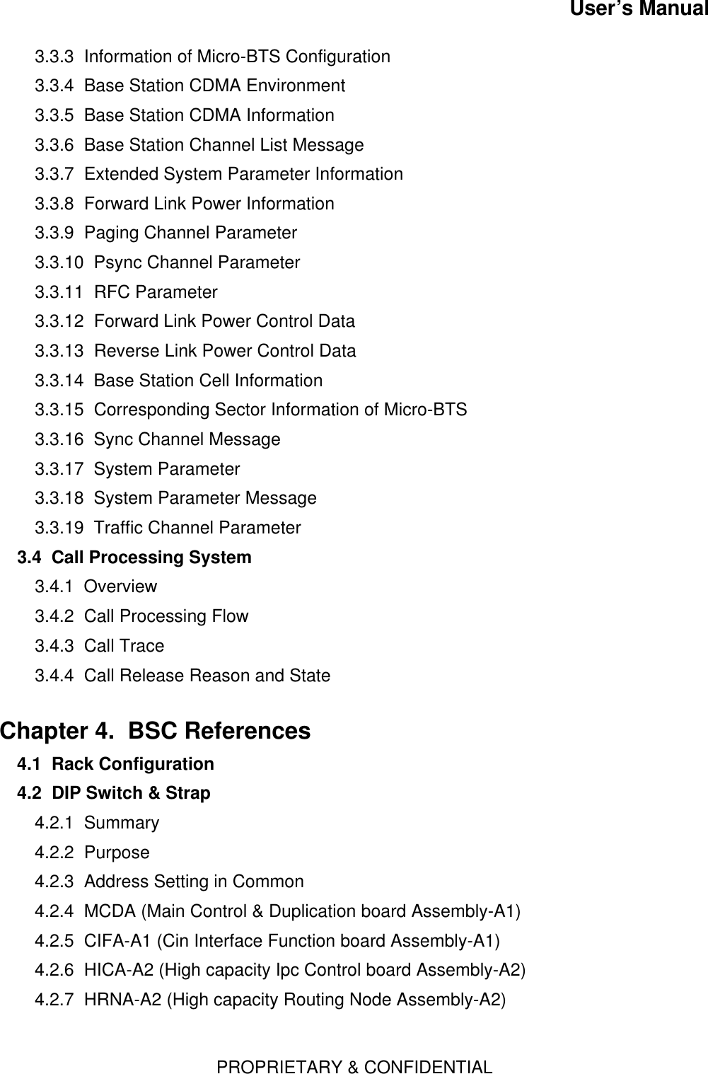
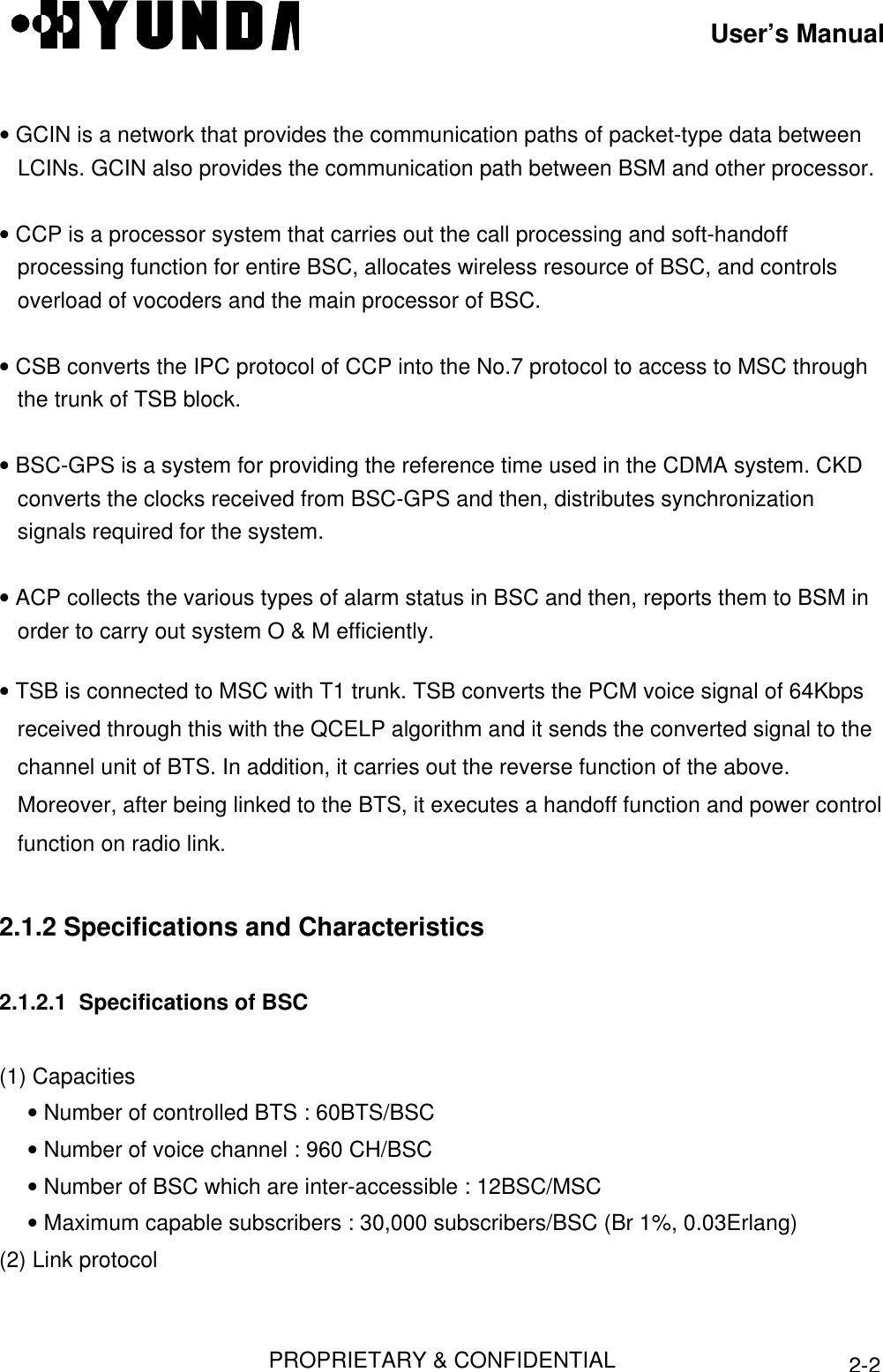
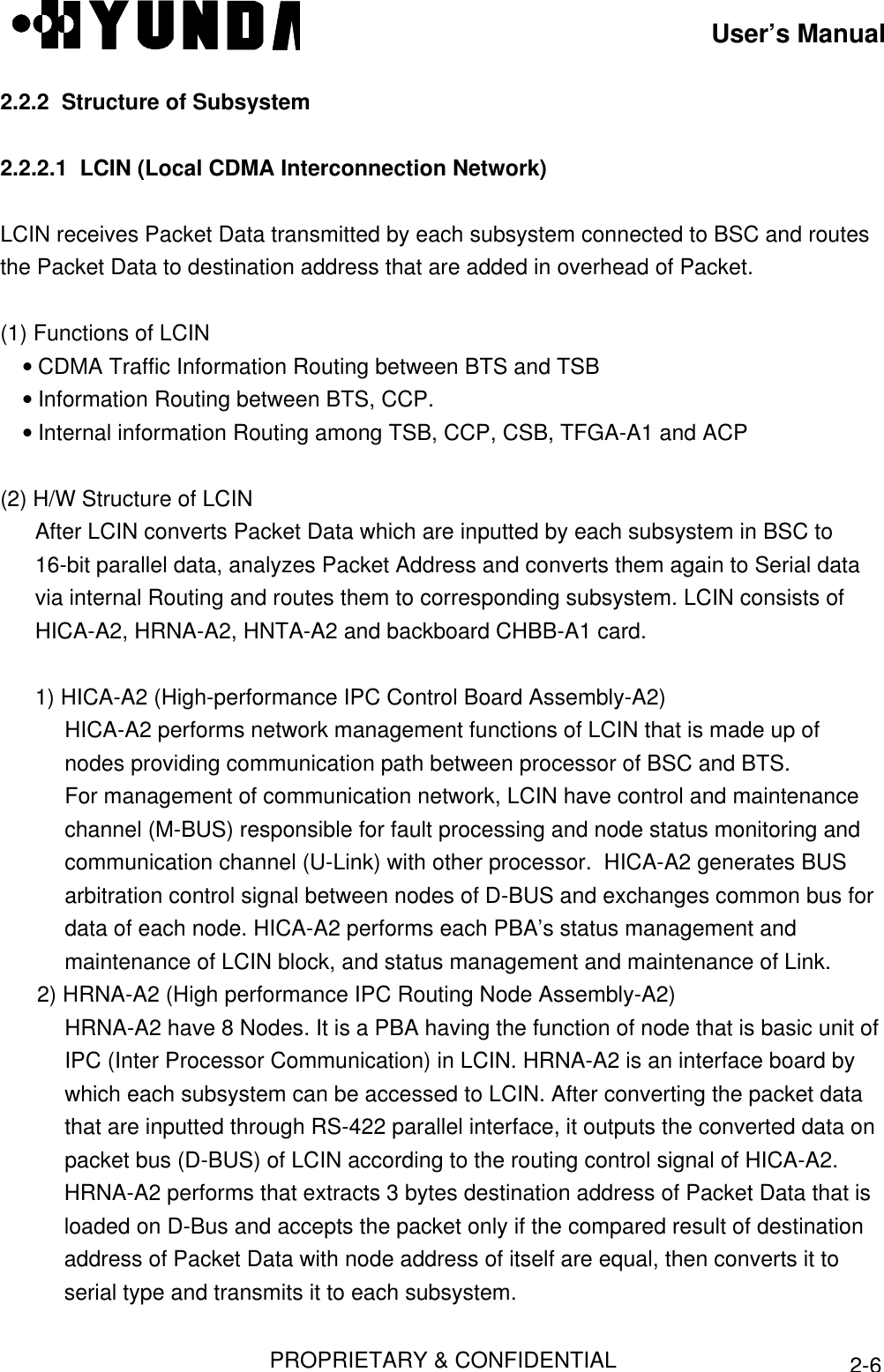
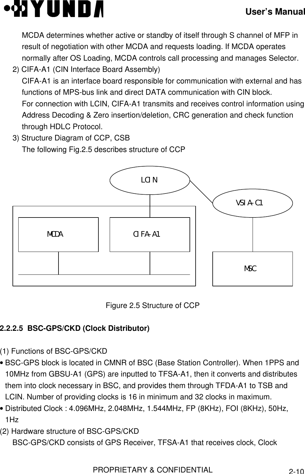
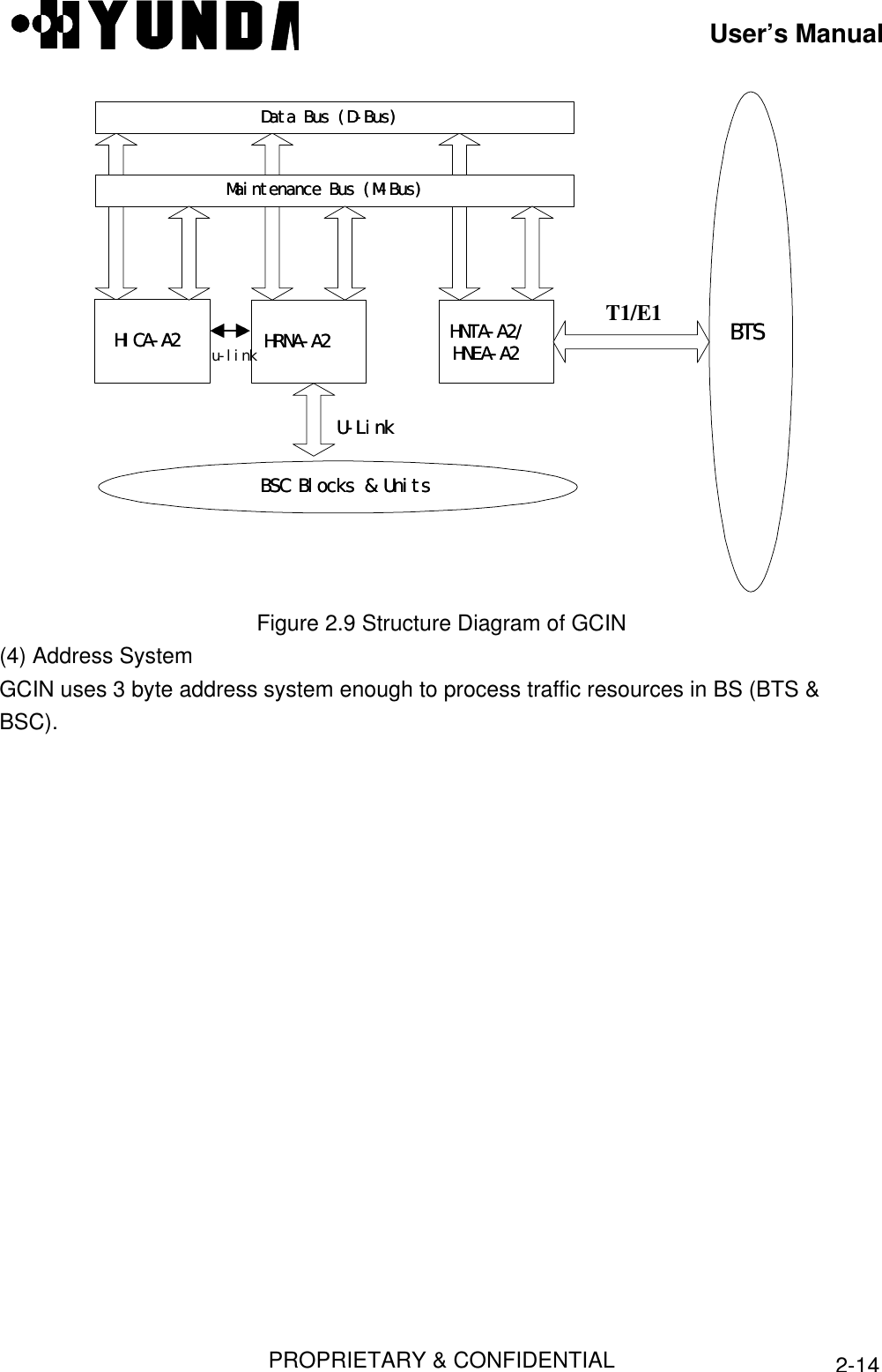
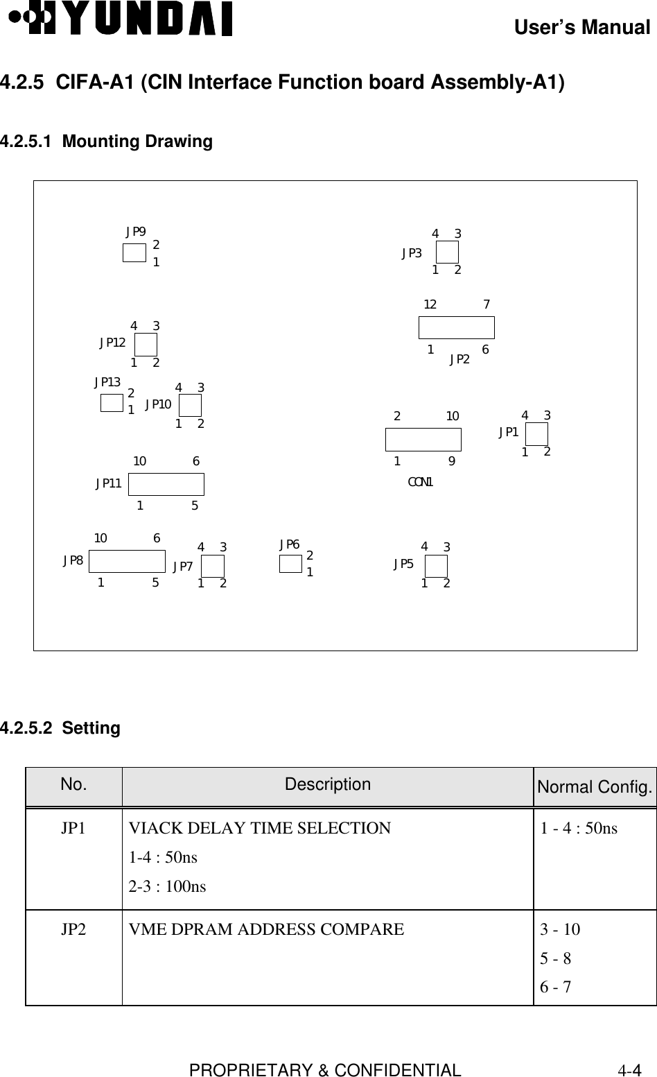
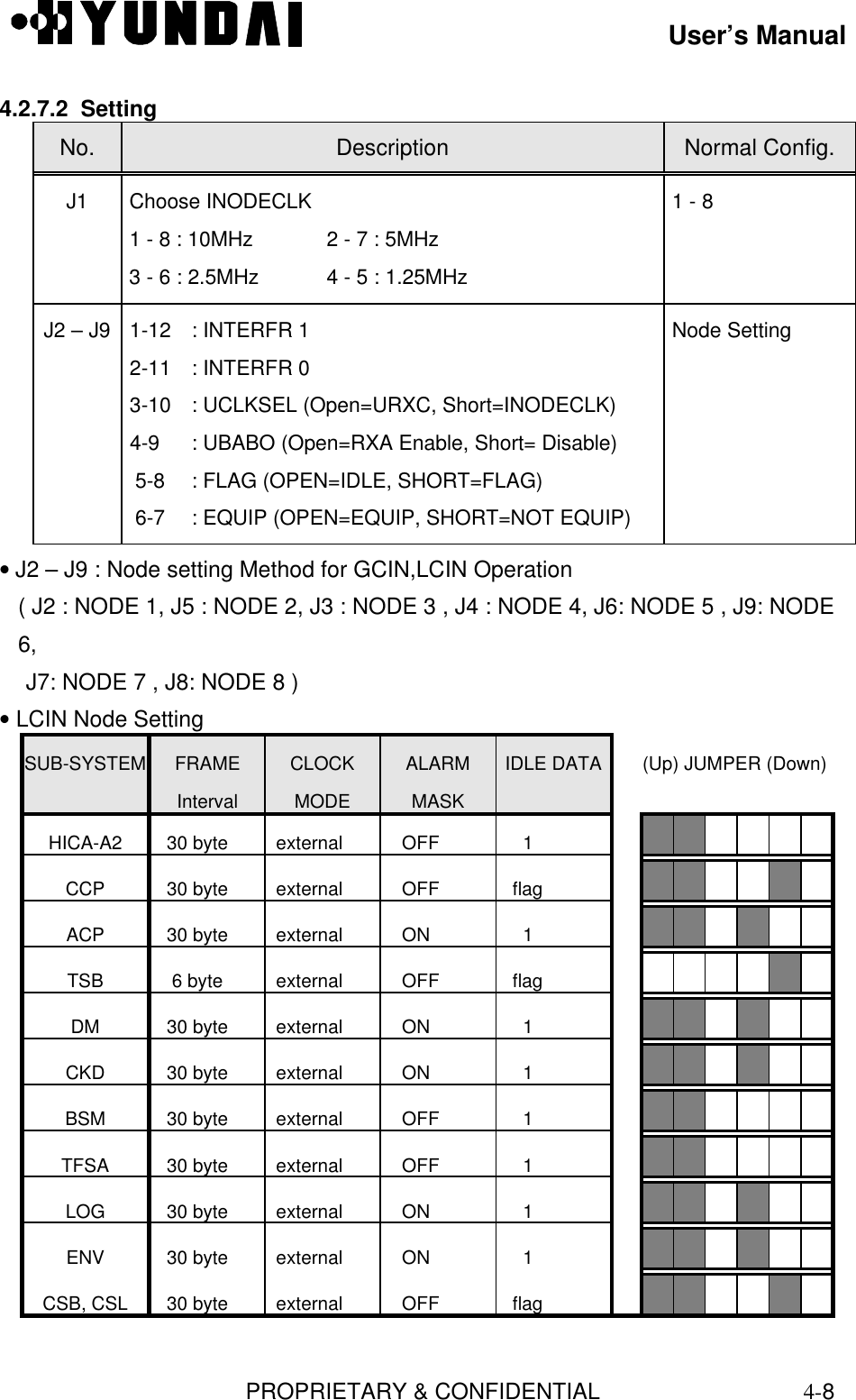
![User’s Manual PROPRIETARY & CONFIDENTIAL 3-38Figure 3.59 BSM Main Screen3.1.6.5.1 Command Re-execution MethodThis provides the simple method of executing the previously executed command. Re-execution of the recently entered 20 commands is available.(1) h CommandEntering h (or H) in the Command window and pressing Enter key displays the list ofrecently entered 20 commands.[ BSMcmd : 40 ] h](https://usermanual.wiki/Hyundai-Electronics-Co/HD-MIC1900/User-Guide-48794-Page-81.png)
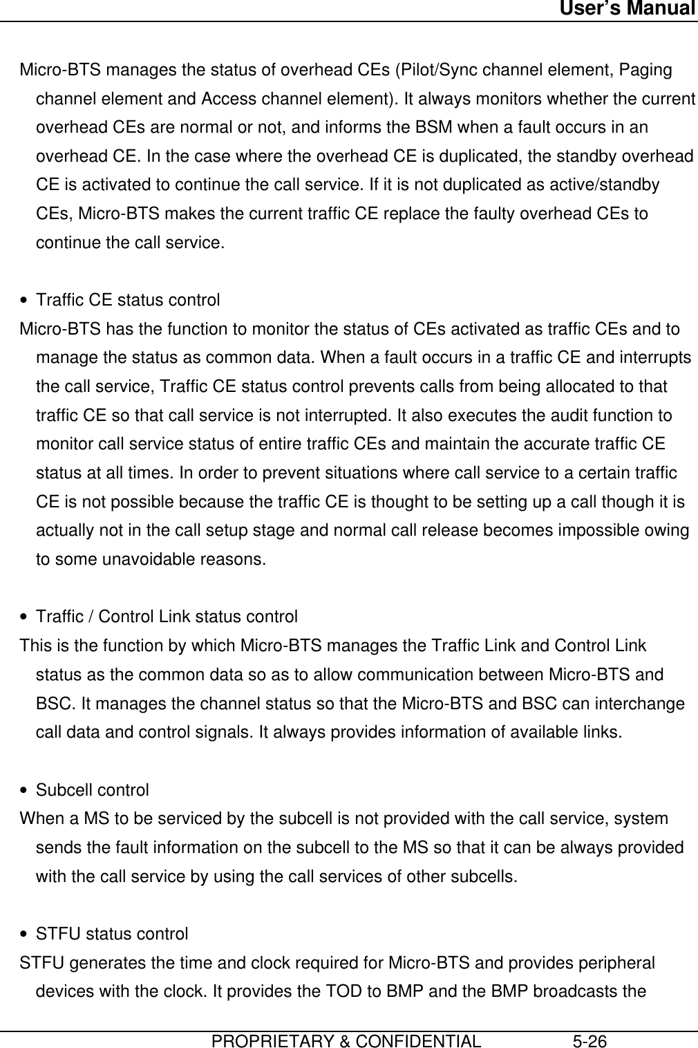
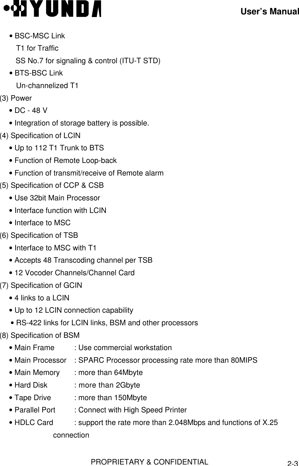
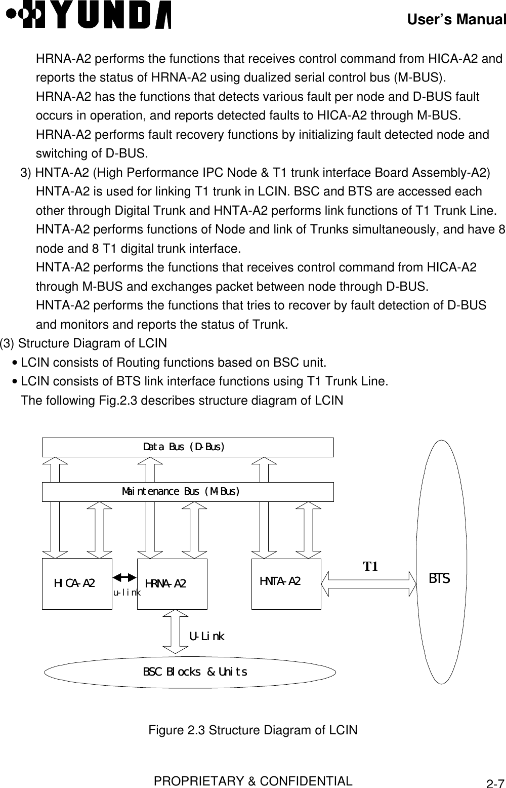
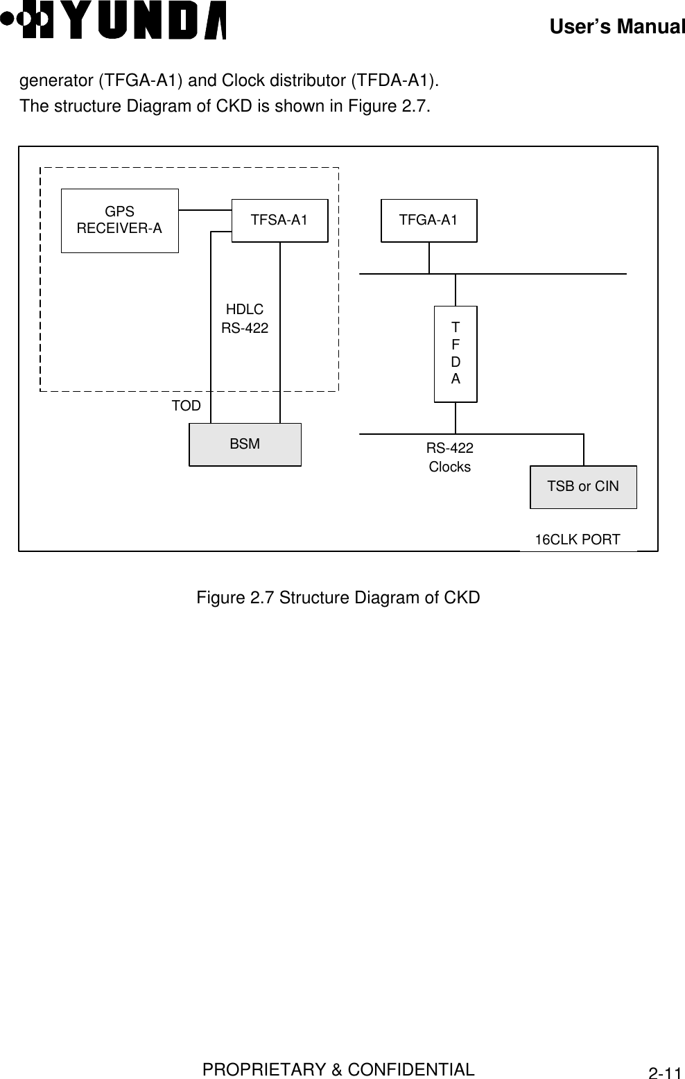
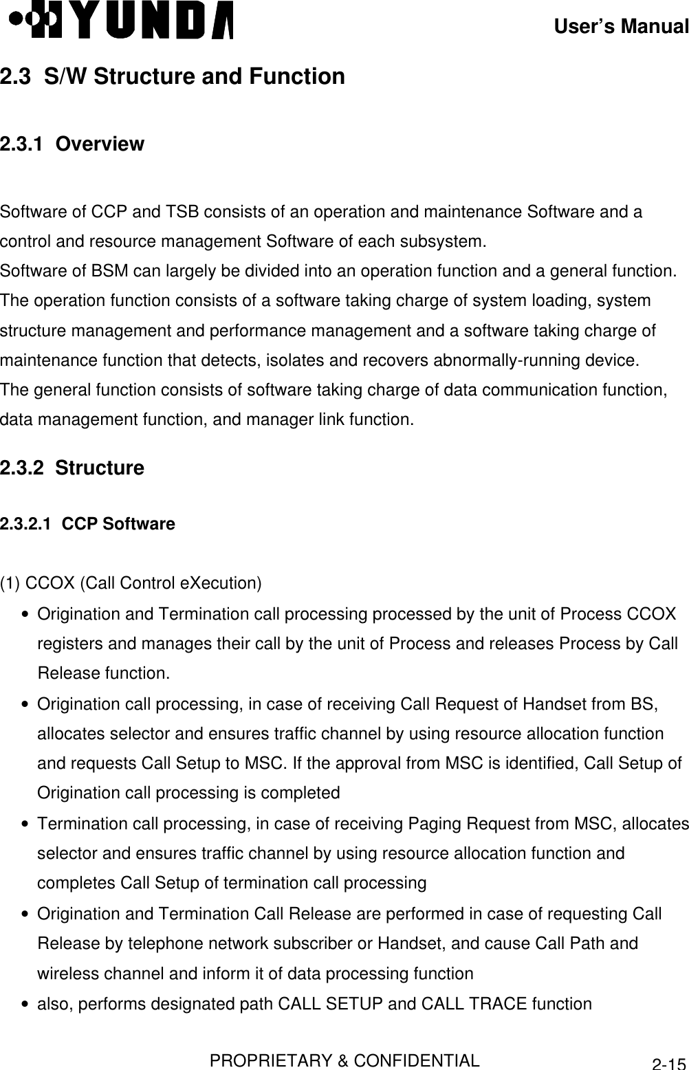
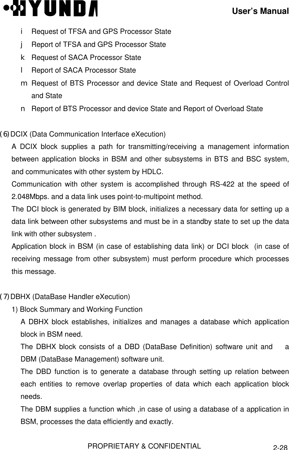
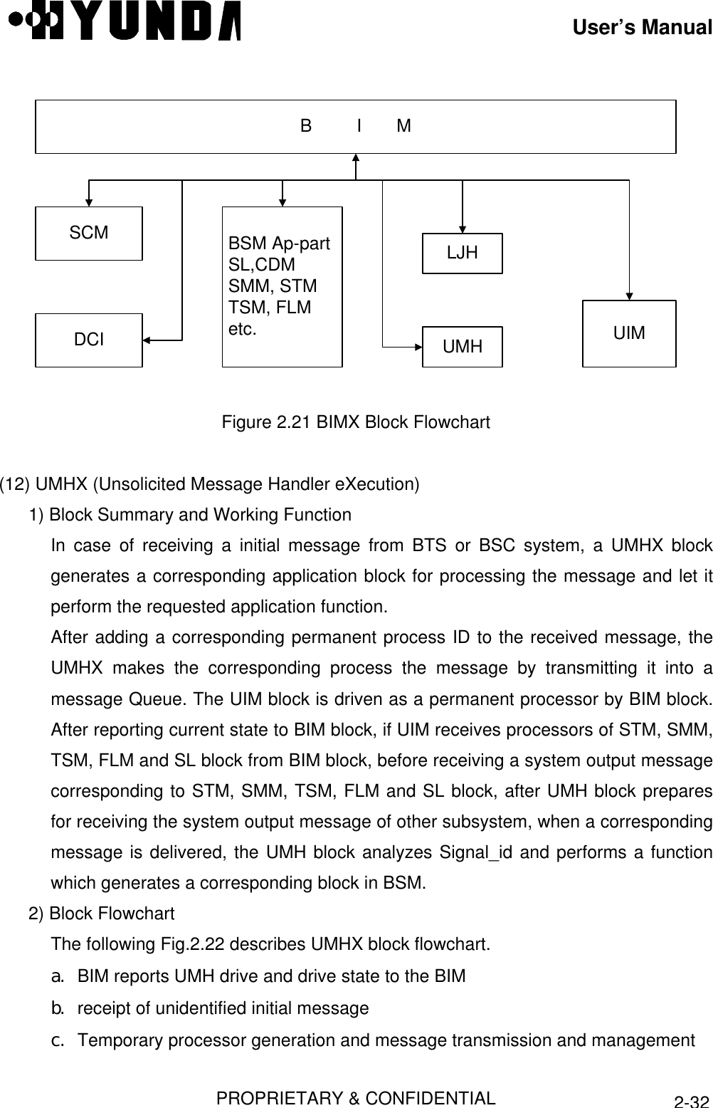
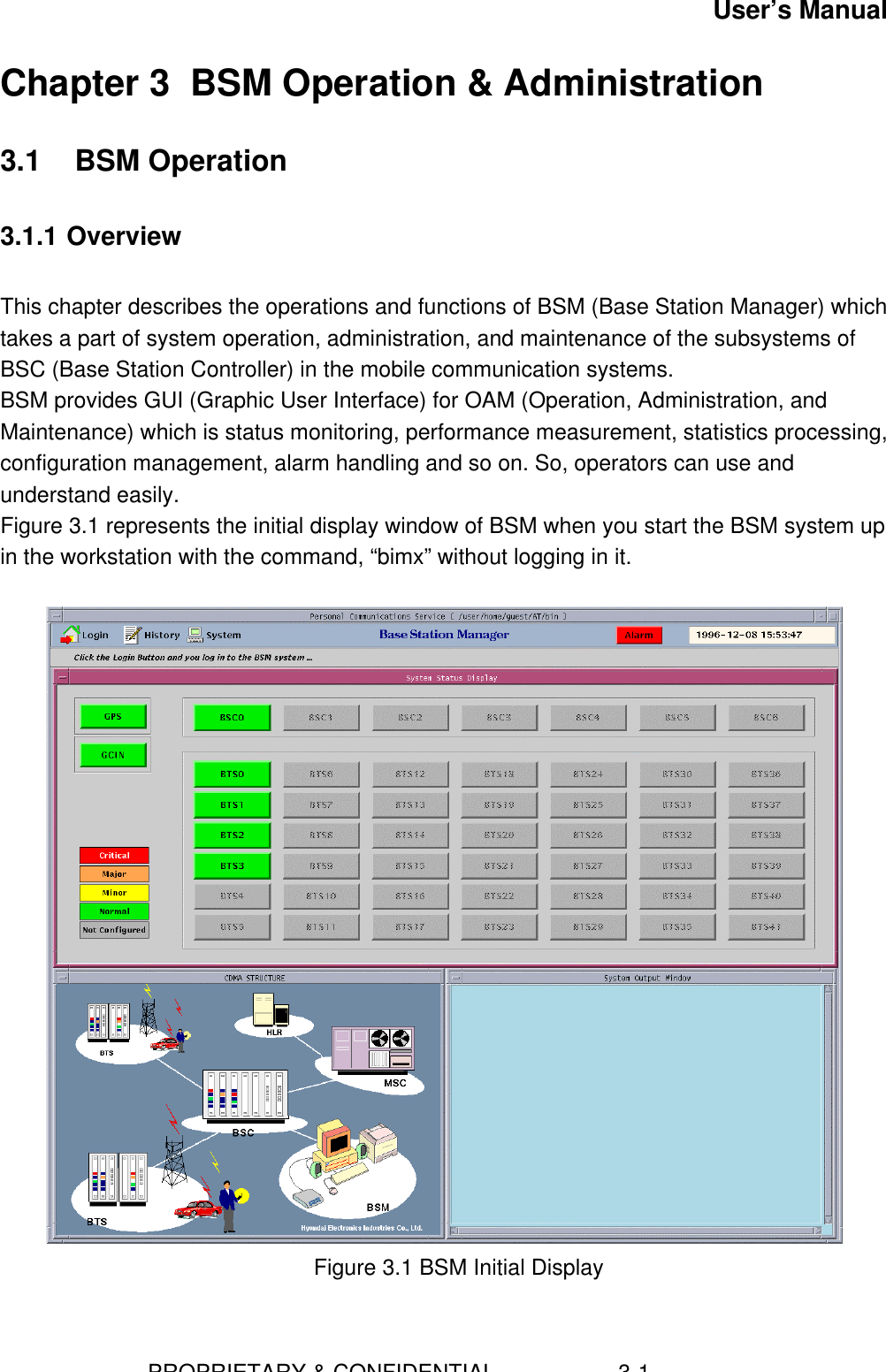
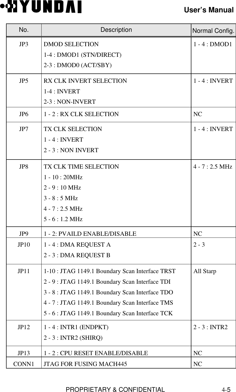
![User’s Manual PROPRIETARY & CONFIDENTIAL 3-3921 DIS-ALM-STS:BSC=0;22 DIS-ALM-STS:BSC=1;23 DIS-ALM-STS:BSC=2;24 DIS-ALM-STS:BSC=3;25 DIS-ALM-STS:BSC=4;26 DIS-ALM-STS:BSC=5;27 DIS-ALM-STS:BSC=6;28 DIS-ALM-STS:BSC=7;29 DIS-ALM-STS:BSC=8;30 DIS-ALM-STS:BSC=9;31 DIS-ALM-STS:BSC=10;32 DIS-ALM-STS:BSC=11;33 DIS-ALM-STS:BTS=0;34 DIS-ALM-STS:BTS=1;35 DIS-ALM-STS:BTS=2;36 DIS-ALM-STS:BTS=3;37 DIS-ALM-STS:BTS=4;38 DIS-ALM-STS:BTS=5;39 DIS-ALM-STS:BTS=6;40 h [ BSMcmd : 41 ]Table Error! No sequence specified.. Example of h Command Result (2) Command Re-execution 1) ! + (Command Number)2) ! + (Command Initial String)3) !! You can re-execute the previously entered command by the above 3 methods. The next table follows the Example of h Command Result of Table 1. 35 DIS-ALM-STS:BTS=2;36 DIS-ALM-STS:BTS=3;37 DIS-ALM-STS:BTS=4;38 DIS-ALM-STS:BTS=5;39 DIS-ALM-STS:BTS=6;40 H](https://usermanual.wiki/Hyundai-Electronics-Co/HD-MIC1900/User-Guide-48794-Page-82.png)
![User’s Manual PROPRIETARY & CONFIDENTIAL 3-40 [ BSMcmd : 41 ] !35Table Error! No sequence specified.. ! + Command Number](https://usermanual.wiki/Hyundai-Electronics-Co/HD-MIC1900/User-Guide-48794-Page-83.png)
![User’s Manual PROPRIETARY & CONFIDENTIAL 3-41 35 DIS-ALM-STS:BTS=2;36 DIS-ALM-STS:BTS=3;37 DIS-ALM-STS:BTS=4;38 DIS-ALM-STS:BTS=5;39 DIS-ALM-STS:BTS=6;40 H [ BSMcmd : 41 ] DIS-ALM-STS:BTS=2;Table Error! No sequence specified.. Result• Input (in italic) as shown in the Table 2 is replaced by the command corresponding tothe number as in the Table 3. Pressing Enter key at this state executes the commandimmediately. If you want to modify the command, edit with the mouse, Delete orBackspace key and press Enter key. 35 DIS-ALM-STS:BTS=2;36 DIS-ALM-STS:BTS=3;37 DIS-ALM-STS:BTS=4;38 DIS-ALM-STS:BTS=5;39 DIS-ALM-STS:BTS=6;40 h [ BSMcmd : 41 ] !DITable Error! No sequence specified.. ! + String 35 DIS-ALM-STS:BTS=2;36 DIS-ALM-STS:BTS=3;37 DIS-ALM-STS:BTS=4;38 DIS-ALM-STS:BTS=5;39 DIS-ALM-STS:BTS=6;40 H [ BSMcmd : 41 ] DIS-ALM-STS:BTS=6;Table Error! No sequence specified.. Result• Input (in italic) as shown in the Table 4 is replaced by the latest command that begins](https://usermanual.wiki/Hyundai-Electronics-Co/HD-MIC1900/User-Guide-48794-Page-84.png)
![User’s Manual PROPRIETARY & CONFIDENTIAL 3-42with the string as in the Table 5. Pressing Enter key at this state executes the commandimmediately. If you want to modify the command, edit with the mouse, Delete orBackspace key and press Enter key. 35 DIS-ALM-STS:BTS=2;36 DIS-ALM-STS:BTS=3;37 DIS-ALM-STS:BTS=4;38 DIS-ALM-STS:BTS=5;39 DIS-ALM-STS:BTS=6;40 h [ BSMcmd : 41 ] DIS-ALM-STS:BSC=0; 1998-04-18 11:40:34 Fri M1004 DISPLAY ALARM STATUS CCP 0 NO ALARM STATUS DISPLAY BCP ALARM COUNT BCP_ID CRI MAJ MIN [ BSMcmd : 42 ] !!Table Error! No sequence specified.. !! Command 38 DIS-ALM-STS:BTS=5;39 DIS-ALM-STS:BTS=6;40 H [ BSMcmd : 41 ] DIS-ALM-STS:BSC=0; 1998-04-18 11:40:34 Fri M1004 DISPLAY ALARM STATUS CCP 0 NO ALARM STATUS DISPLAY BCP ALARM COUNT BCP_ID CRI MAJ MIN [ BSMcmd : 42 ] DIS-ALM-STS:BSC=0;Table Error! No sequence specified.. Result • Input (in italic) as shown in the Table 6 is replaced by the previously executed command](https://usermanual.wiki/Hyundai-Electronics-Co/HD-MIC1900/User-Guide-48794-Page-85.png)
![User’s Manual PROPRIETARY & CONFIDENTIAL 3-43as in the Table 7. Pressing Enter key at this state executes the command immediately. Ifyou want to modify the command, edit with the mouse, Delete or Backspace key andpress Enter key.3.1.6.5.2 Help Command in the Command Handling Window(1) (Command + ‘?’)• In command window, if you want to print the command help, you must input “command+ ‘?’” or “command + ‘?’+’;’”.[ BSMcmd : 1 ] CHG-SECT-INFO? or CHG-SECT-INFO?;1998-07-02 09:37:34 Thu• CHG-SECT-INFO HELP MESSAGE• Change Sector Information.CHG-SECT-INFO : {BSC=bsc, BCP=bcp}, SECT = sect {[Param]} ; {BTS=bts }bsc BSC id (0-11)bcp BCP id (0-31)bts BTS id (0-383)sect Sector id (ALPHA, BETA, GAMMA)Param :PILOT Pilot OffsetTXFA Tx Fine AdjustTXCA Tx Coarse AdjustRXFA Rx Fine AdjustRXCA Rx Coarse AdjustRTDTHR Common Round Trip Delay ThreshCYCIDX Max Slot Cycle IndexPREV CAI RevisionPMREV CAI Minimum Revision(2) ?XXX (‘?’ + string)](https://usermanual.wiki/Hyundai-Electronics-Co/HD-MIC1900/User-Guide-48794-Page-86.png)
![User’s Manual PROPRIETARY & CONFIDENTIAL 3-44• If you attatched ‘?’ at any string, you can see all commands involving the string. [ BSMcmd : 1 ] ?SECT1 CHG-SECT-INFO2 DIS-SECT-INFO [ BSMcmd : 2 ] ?CE3 CHG-CE-CONF4 CHG-CE-TYPE5 CHG-SCEL-INFO6 DIS-CE-STS7 DIS-PN-CELL8 DIS-SCEL-INFO9 DIS-TCE-STS10 STRT-STAT-CE11 TST-CE [ BSMcmd : 3 ] ?-CE-12 CHG-CE-CONF13 CHG-CE-TYPE14 DIS-CE-STS [ BSMcmd : 3 ] ?1 ACT-LINK2 ACT-LSET3 ACT-OVLD-THR4 ADD-LDNG-BLK5 ADD-NEBR6 ALW-ALM-MSG . . . 248 TST-SVE 249 UINH-LINK All commands are displayed.](https://usermanual.wiki/Hyundai-Electronics-Co/HD-MIC1900/User-Guide-48794-Page-87.png)
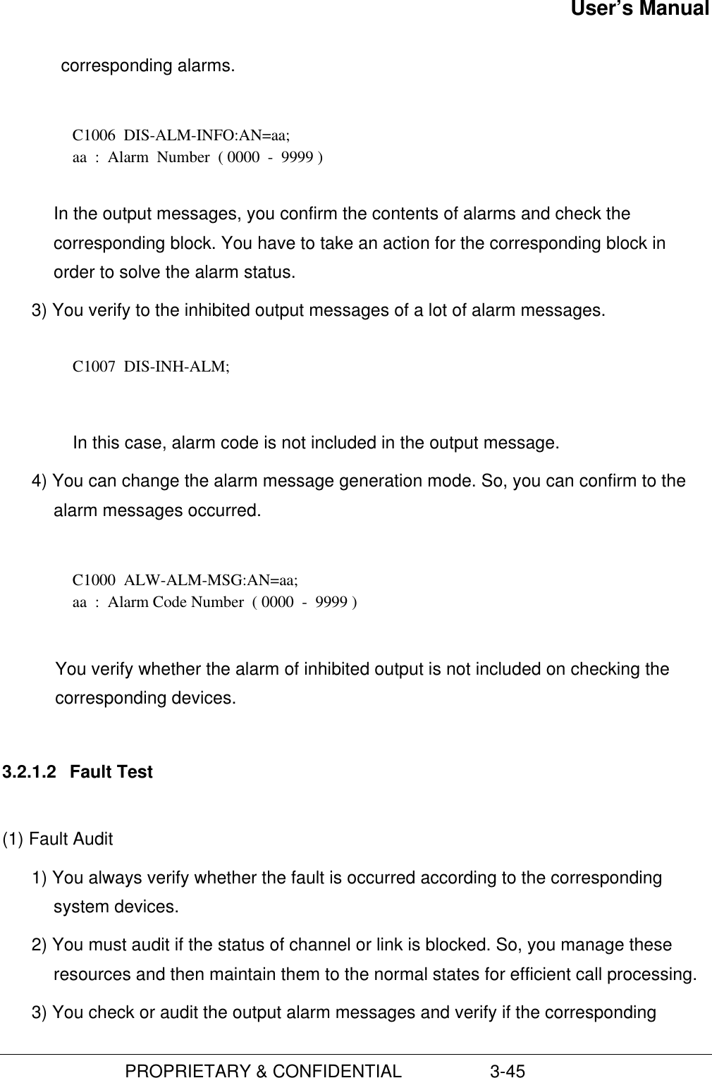
![User’s Manual PROPRIETARY & CONFIDENTIAL 3-443.2 System Status Management3.2.1 System Status TestBSC system may always audit and monitor processor status, alarm status, channel andlink status whether the call is normal. If the status is abnormal or system has a certainfault, BSC system may take an action and then maintain the active status of system.3.2.1.1 Alarm Test(1) Alarm Monitoring1) If the BSC system is an abnormal status or makes a certain fault, system may bealerting the alarms. So, it must maintain the audible or visible alarm status in order tooutput and create an alarm.2) If you inhibited the audible or visible alarm, you must be always aware of notoutputting those alarms when the system is an abnormal status or a fault.3) In reporting alarms to the system, it outputs the content of alarm and it checks thecorresponding block automatically. So, it solves the problems to the reported alarm.4) You input a command of outputting alarm status and verify whether the alarm isoccurred.(2) Alarm Test1) You enable the system to output the alarm messages created until now. C1004 DIS-ALM-STS:[BSC=aa[,BCP=bb],BTS=cc]; aa : BSC ID bb : BCP ID cc : BTS ID You make sure of the number of alarm messages in the corresponding block.2) You are able to output the alarm message information and then confirm the](https://usermanual.wiki/Hyundai-Electronics-Co/HD-MIC1900/User-Guide-48794-Page-88.png)
![User’s Manual PROPRIETARY & CONFIDENTIAL 3-46devices are faults or abnormal.(2) Fault Test for the listed items1) You make sure whether the channel or link is blocked. C3306 DIS-OOS-STS:BSC=aa,[BCP=bb,]DEV=cc,TYPE=dd; aa : BSC ID bb : BCP ID cc : DEVICE TYPE ( SVE/MLNK/BLNK/TCE ) dd : Type ( MBLK/FBLK/TBLK ) 2) You verify which fault message is inhibited. C1008 DIS-INH-FLT; The code of inhibiting message dose not report to the system. 3) When you want to print the inhibited fault message, you must release the messagesthat cannot print or report to the system. Therefore, you have to allow the messagesto print.C1002 ALW-FLT-MSG:FN=aa;aa : Fault CodeNumber ( 0000 - 9999 )3.2.1.3 Test for control of processor status(1) The status audit of processor1) You always verify whether the status of processors is normal.2) You change the status of stand-by processor to active processor and verify if thestatus of this processor is normal or abnormal.3) If the status of processor is abnormal, you have to repair it rapidly.4) For the processor is the main part of system, you have to maintain that one or more](https://usermanual.wiki/Hyundai-Electronics-Co/HD-MIC1900/User-Guide-48794-Page-90.png)
![User’s Manual PROPRIETARY & CONFIDENTIAL 3-47than processor is normal at least.(2) Status test of processor1) You verify if the status of CCP in the system is normal. C3001 DIS-CCP-STS:[BSC=aa]; aa : BSC ID If you don’t input the corresponding BSC ID, you can verify the statues of allCCPs.2) After you check and verify the status of processors, you switch over the status ofprocessor. C2012 SWT-PRC:BSC=aa,PROC=CCP; aa : BSC ID You check the output message and verify if CCP is switched over in that message.After the processor is switched over, you verify if its status is normal. If the systemdoes not have a standby processor, that is, it has only one processor, this commandis unable to be executed. 3) You verify the status of SIP in the system. C3002 DIS-SIP-STS:BSC=aa; aa : BSC ID 4) You check the status of SVP in the system. C3003 DIS-SVP-STS:BSC=aa,[SIP=bb]; aa : BSC ID bb : SIP ID 5) You verify the status of ACP in the system.](https://usermanual.wiki/Hyundai-Electronics-Co/HD-MIC1900/User-Guide-48794-Page-91.png)
![User’s Manual PROPRIETARY & CONFIDENTIAL 3-48 C3401 DIS-BSC-ACP:[BSC=aa]; aa : BSC ID 6) You verify whether the processors of BTS are normal or abnormal. C3101 DIS-BTS-PRC:BSC=aa,BCP=bb[,BTS=cc]; aa : BSC ID bb : BCP ID cc : BTS ID 7) You check whether the status of cards or boards in BTS is normal.C3102 DIS-BTS-CARD:BSC=aa,BCP=bb[,BTS=cc],CARD=dd,MIC_CARD=ee;aa : BSC IDbb : BCP IDcc : BTS IDdd : SRC,TCC,TCU,TFC,BIC,GPS,AMPee : UP,DOWN,SYNU,BIC,STFU,RFRU3.2.1.4 Status test for links and channels(1) Status audit of links and channels1) You verify if the statuses of links and channels are normal.2) When the links of BTS is blocked, you note that the call is cut off.3) When the links and channels are blocked, you use TST command to check thestates of them.(2) Status test of links1) You check whether the status of MSC-links is normal. C3005 DIS-MLNK-STS:BSC=aa; aa : BSC ID 2) You verify the status of BTS-links.](https://usermanual.wiki/Hyundai-Electronics-Co/HD-MIC1900/User-Guide-48794-Page-92.png)
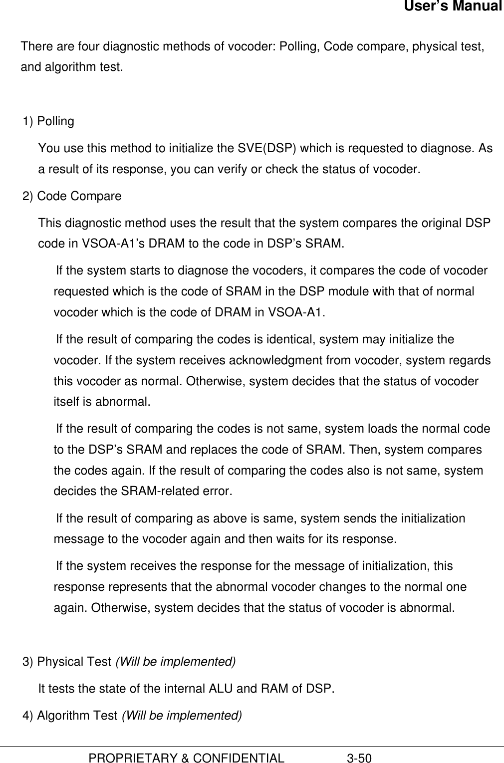
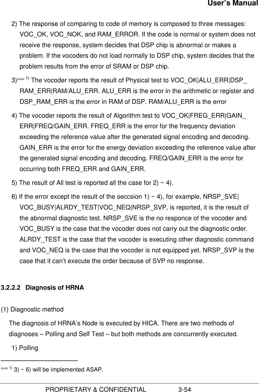
![User’s Manual PROPRIETARY & CONFIDENTIAL 3-49C3007 DIS-BLNK-STS:[BSC=aa,BCP=bb];[BTS=c]aa : BSC IDbb : BCP IDcc : BTS ID(3) Status test of channel1) You check the status of vocoder. C3004 DIS-SVE-STS:BSC=aa,SIP=bb[,SVP=cc]; aa : BSC ID bb : SIP ID cc : SVP ID 2) You verify the status of CE.C3106 DIS-CE-STS:BSC=aa,BCP=bb[,BTS=cc],DU=dd;aa : BSC IDbb : BCP IDcc : BTS IDdd : DU ID3.2.2 System DiagnosisDiagnosis is the testing of resources that are closely related to call processing in operatingthe system and its results is reported to the operators. If its results are abnormal, youexclude this resource for the service of call process. If the resource of call process isrecoverable, you enable this resource to use the call services or to add the resource poolof system immediately.3.2.2.1 Diagnosis of vocoder(1) Diagnostic method](https://usermanual.wiki/Hyundai-Electronics-Co/HD-MIC1900/User-Guide-48794-Page-93.png)
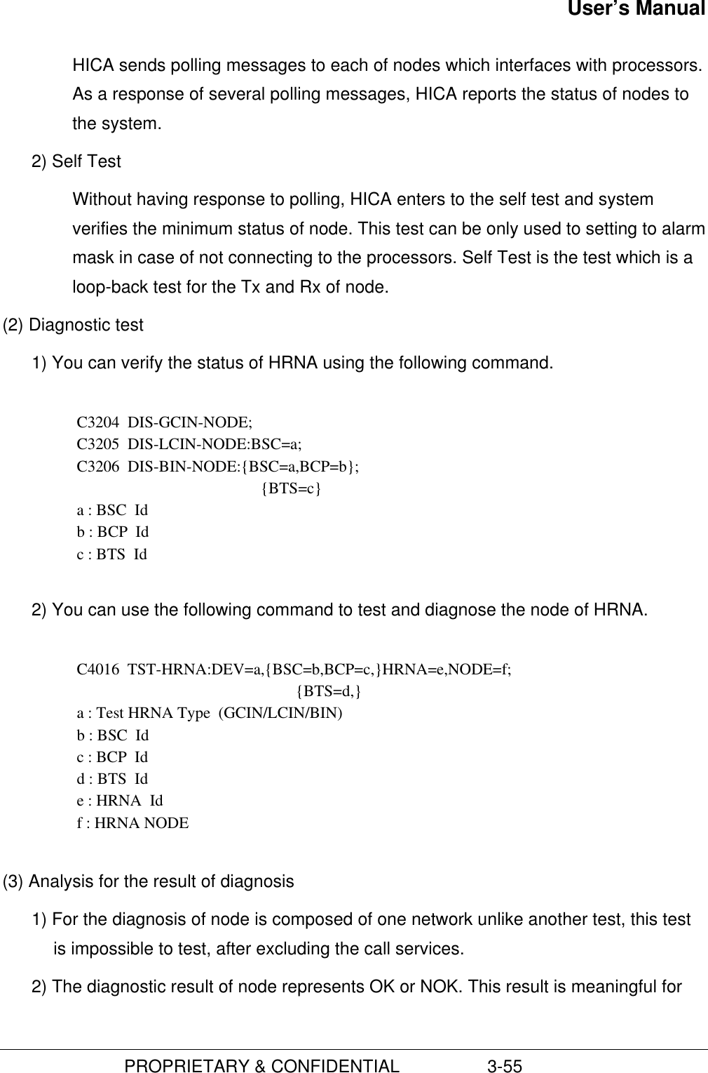
![User’s Manual PROPRIETARY & CONFIDENTIAL 3-53(2) Diagnostic Test1) You can use the following command to verify the status of vocoder. C3004 DIS-SVE-STS:BSC=a,SIP=b[,SVP=c]; a : BSC Id b : SIP Id c : SVP Id 2) Next, you test the vocoder using the following command.C4017 TST-SVE:BSC=a,SIP=b[,SVP=c,SVE=d],LEVEL=e,ALGORITHM=f;a : BSC Idb : SIP Idc : SVP Idd : SVE Ide : Test Level (POLL_TST/CODE_CMP/PHYSICAL_TST/ALGORITHM_TST/ALL)f : Vocoder algorithm (QCELP_8K/QCELP_13K/EVRC)(3) Inter-working with call processing1) For vocoder is related with call processing directly, you can confirm enough todiagnose the status of it.2) In case of maintaining call, system decides on the normal state of vocoder. Systemneed not to diagnose, and reports the “BUSY” state to the operators.3) If the vocoder is idle, system changes its state to test block (T_BLK) in order not touse this resource not to set a call on diagnosing. And then, system enters todiagnose.4) After the diagnosis end up, system changes the state to idle and is able to use orset a call service.(4) Analysis for result of diagnosis1) As a result of polling, vocoder sends VOC_OK/VOC_NOK to the system. If thesystem is not able to receive the response normally, it decides on the abnormalstate of vocoder.](https://usermanual.wiki/Hyundai-Electronics-Co/HD-MIC1900/User-Guide-48794-Page-97.png)
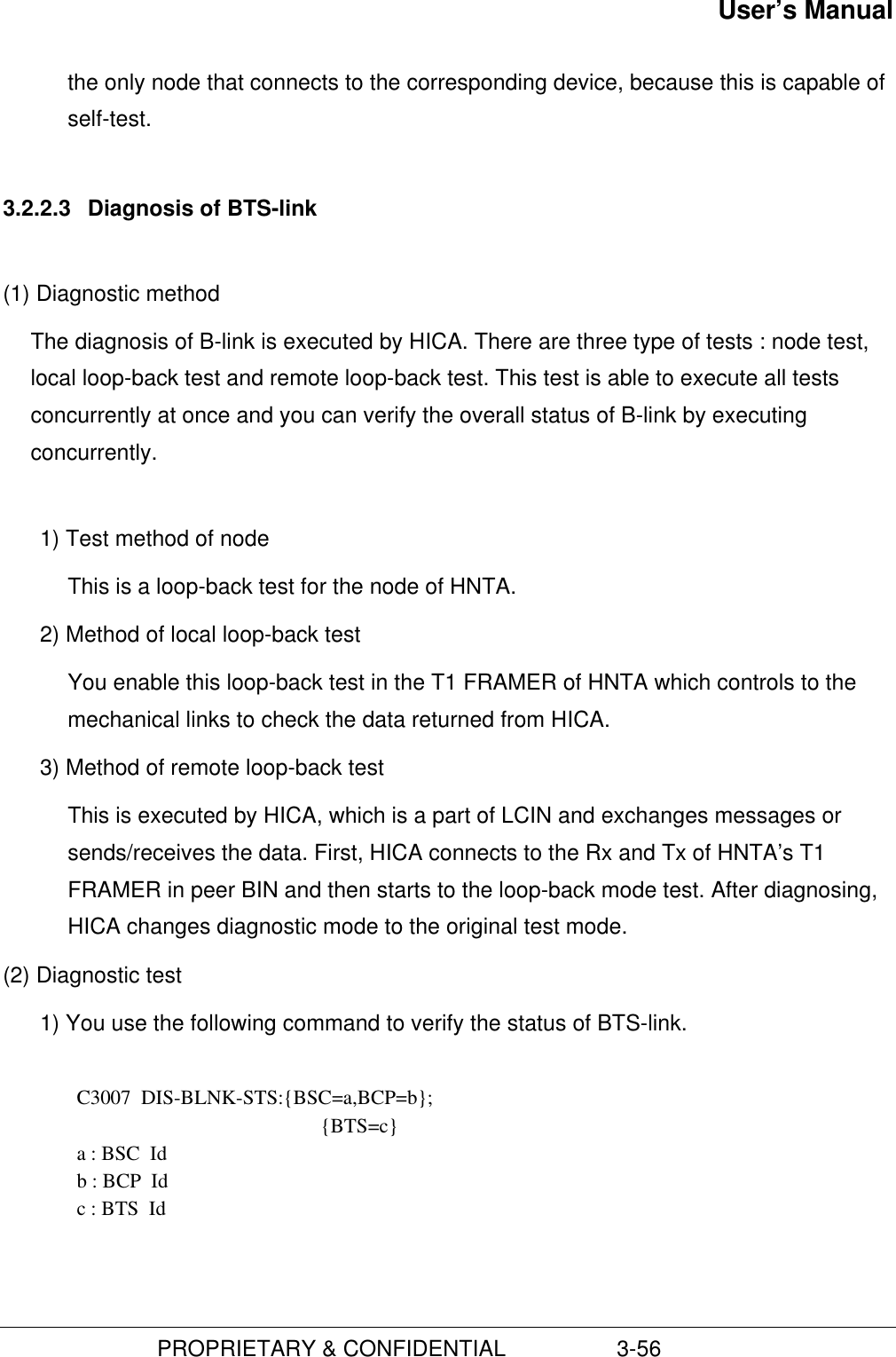
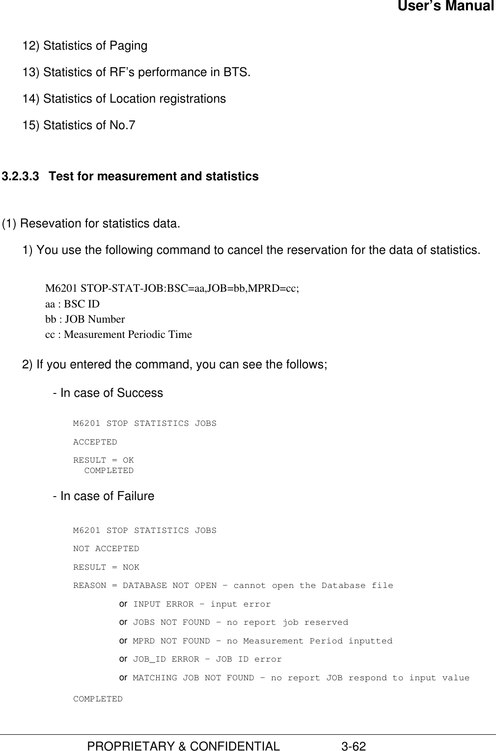
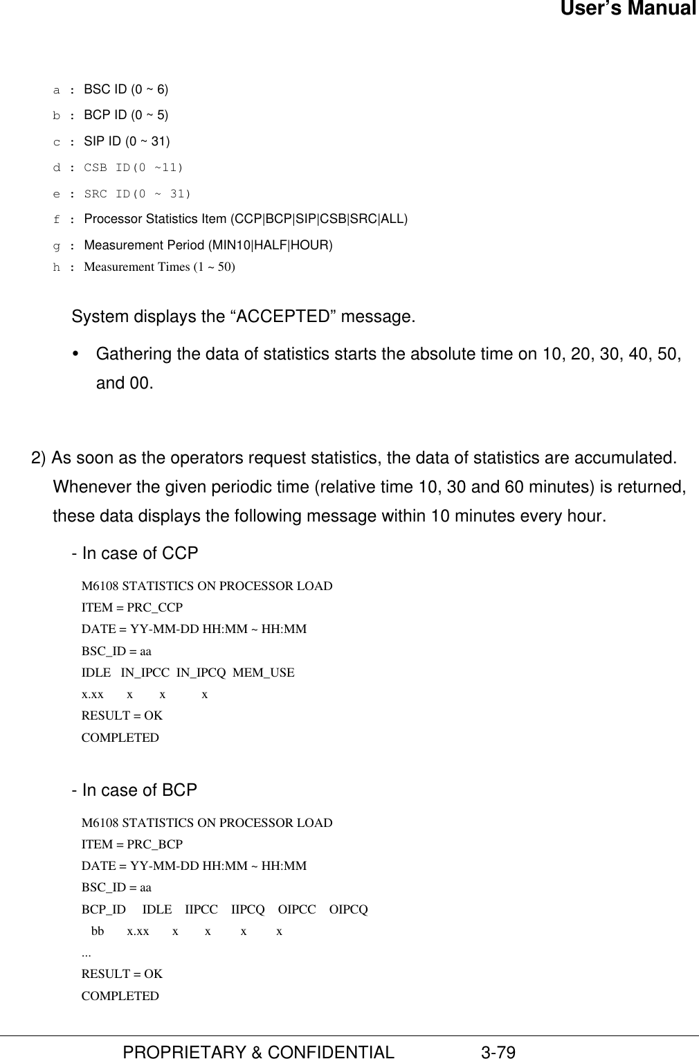
![User’s Manual PROPRIETARY & CONFIDENTIAL 3-633) You use the following command to cancel the reservation for the data of statisticsM6001 DIS-STAT-JOB:bsc=bsc;bsc : BSC ID4) If you entered the command, you can see the follows;- In case of SuccessM6001 DISPLAY STATISTICS JOBSBSC = bsc_idSUB_ID JOB_NO STAT_ITEM START_TIME MPRD MTIM ITER aa bb cc dd ee ff gg...RESULT = OKCOMPLETEDaa : SUB IDbb : JOB Registration Numbercc : JOB Statistics Itemdd : Measurement Start Timeee : Measurement Periodff : Measurement Timesgg : Execution Times- In case of FailureM6001 DISPLAY STATISTICS JOBSNOT ACCEPTEDRESULT = NOKREASON = Fail Reasons*COMPLETEDREASON = BSC NOT EQUIPPED – The entered BSC is not equipped.or NO JOBS PLANNED – There is not reserved ststistics JOB.or BSC_ID NOT ENTERED – Input Error for not entered BSC.(2) Statistics of trafficThere are three types of the measurement and statistics of traffic according toorigination call, termination call, and both of all.1) You use the following command to start up the traffic command.C6102 STRT-STAT-TRAF:[BSC=a,[BCP=b,]]ITEM=c,MPRD=d,MTIM=e; a : BSC ID (0 ~ 6) b : BCP ID (0 ~ 5) c : Statistics of Traffic ITEM (ORG|TER|ALL) d : Measurement Periodical Time (MIN10|HALF|HOUR)](https://usermanual.wiki/Hyundai-Electronics-Co/HD-MIC1900/User-Guide-48794-Page-107.png)
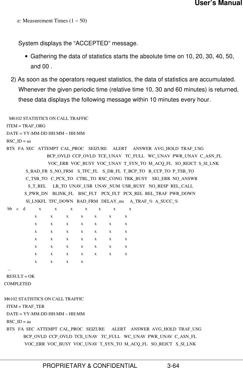
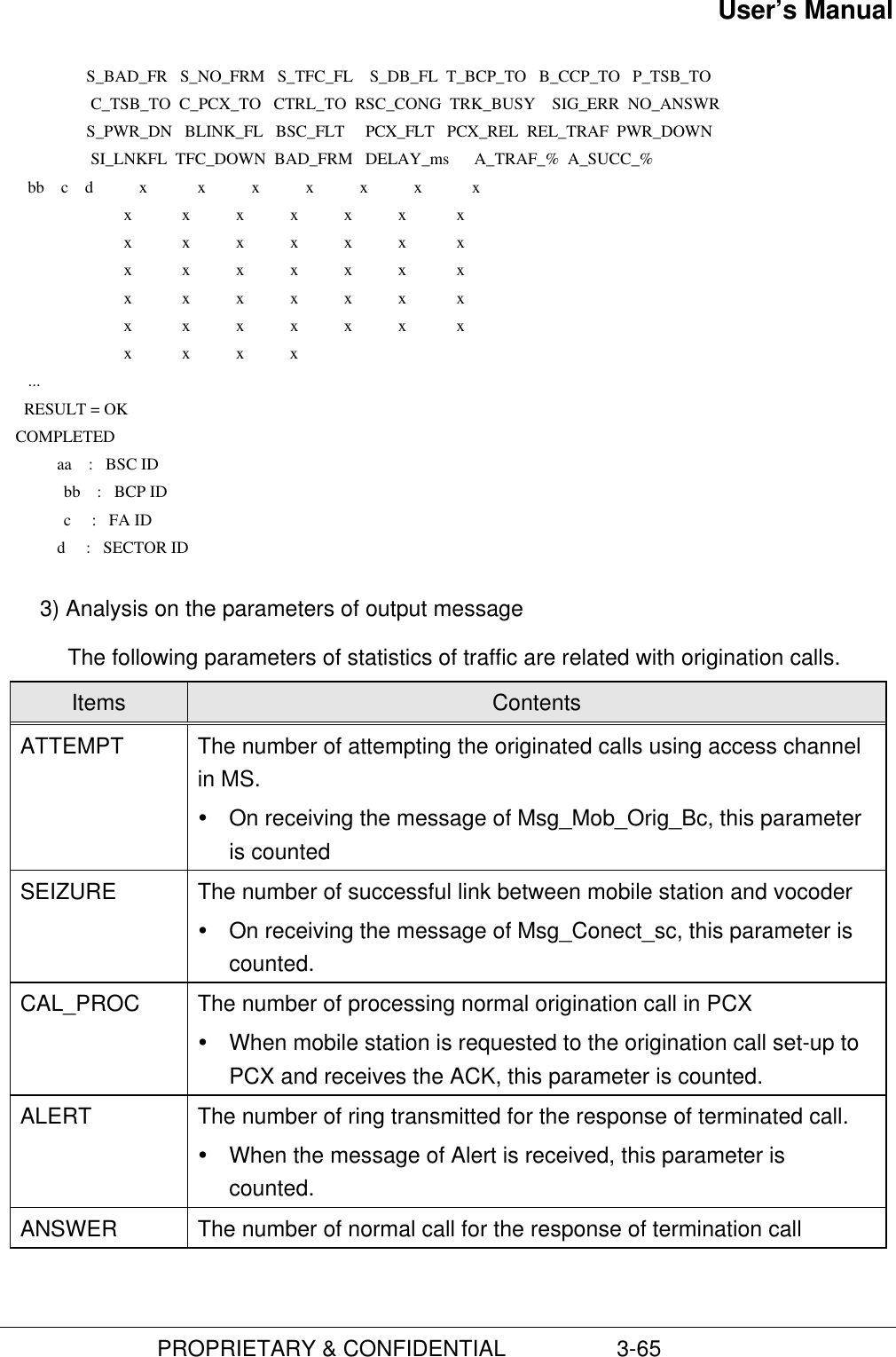
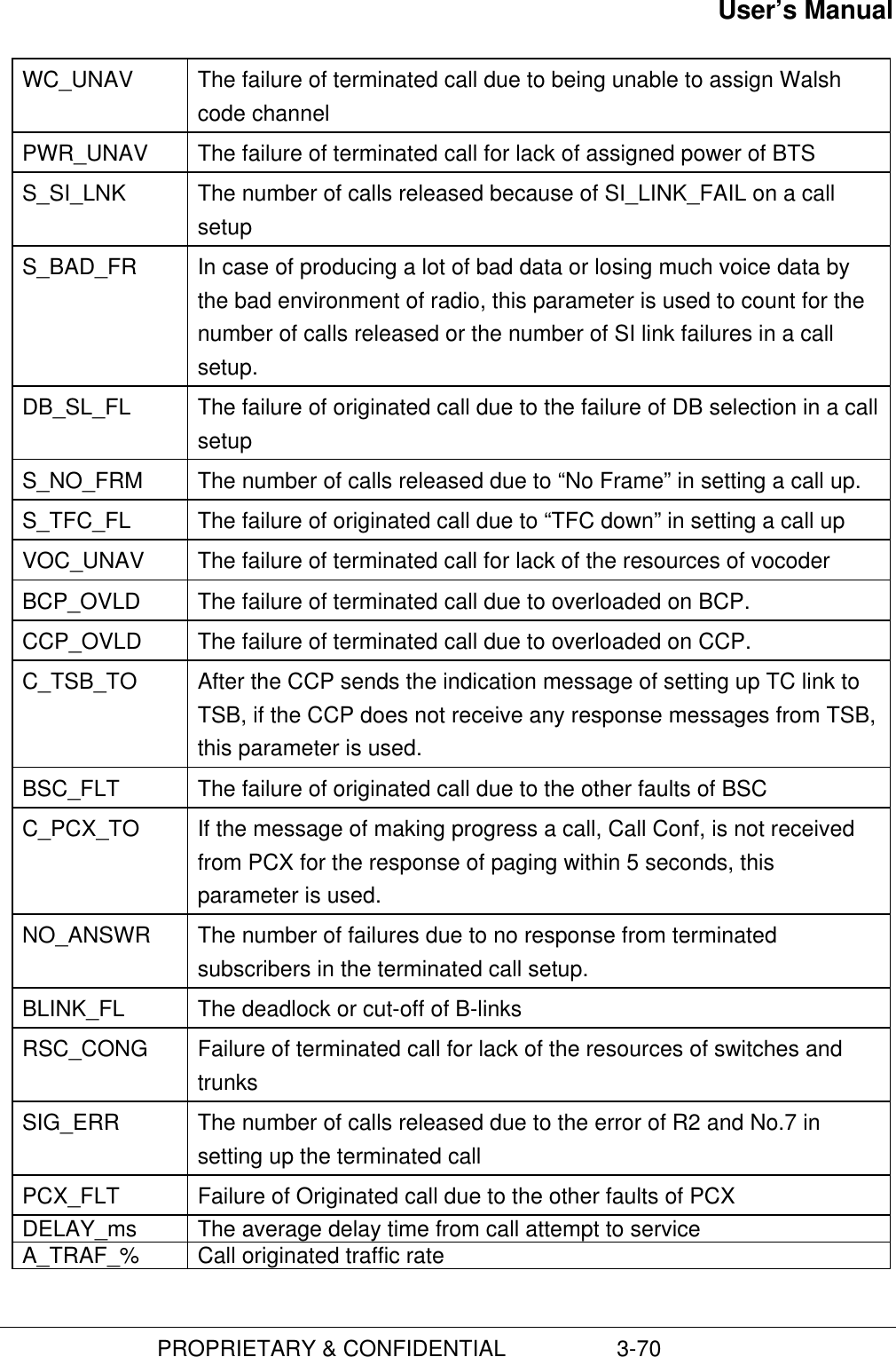
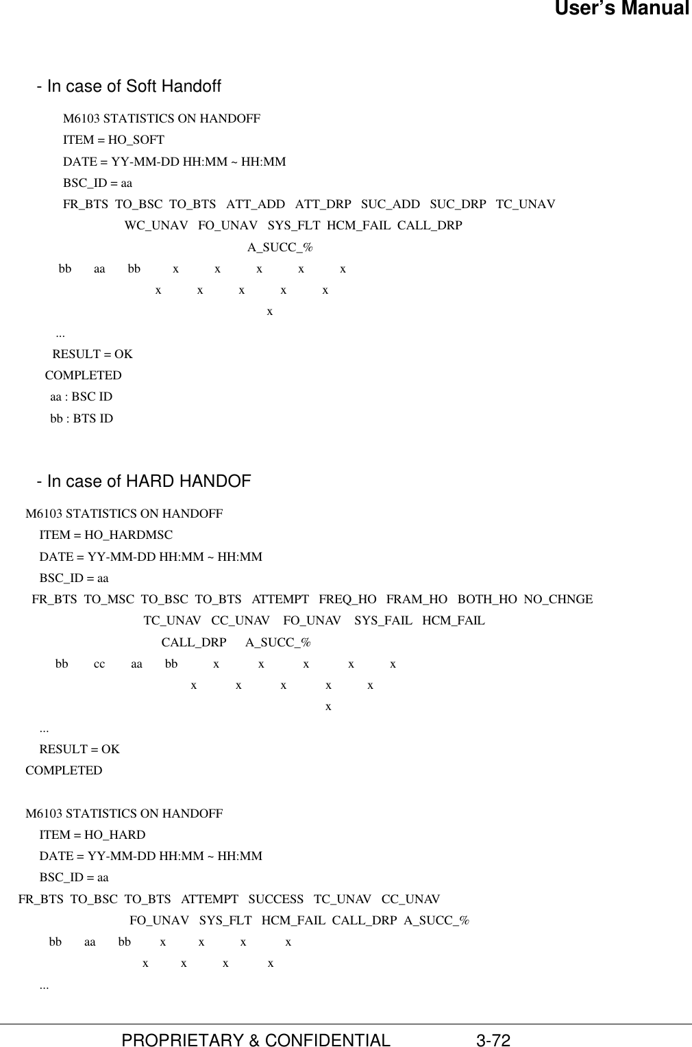
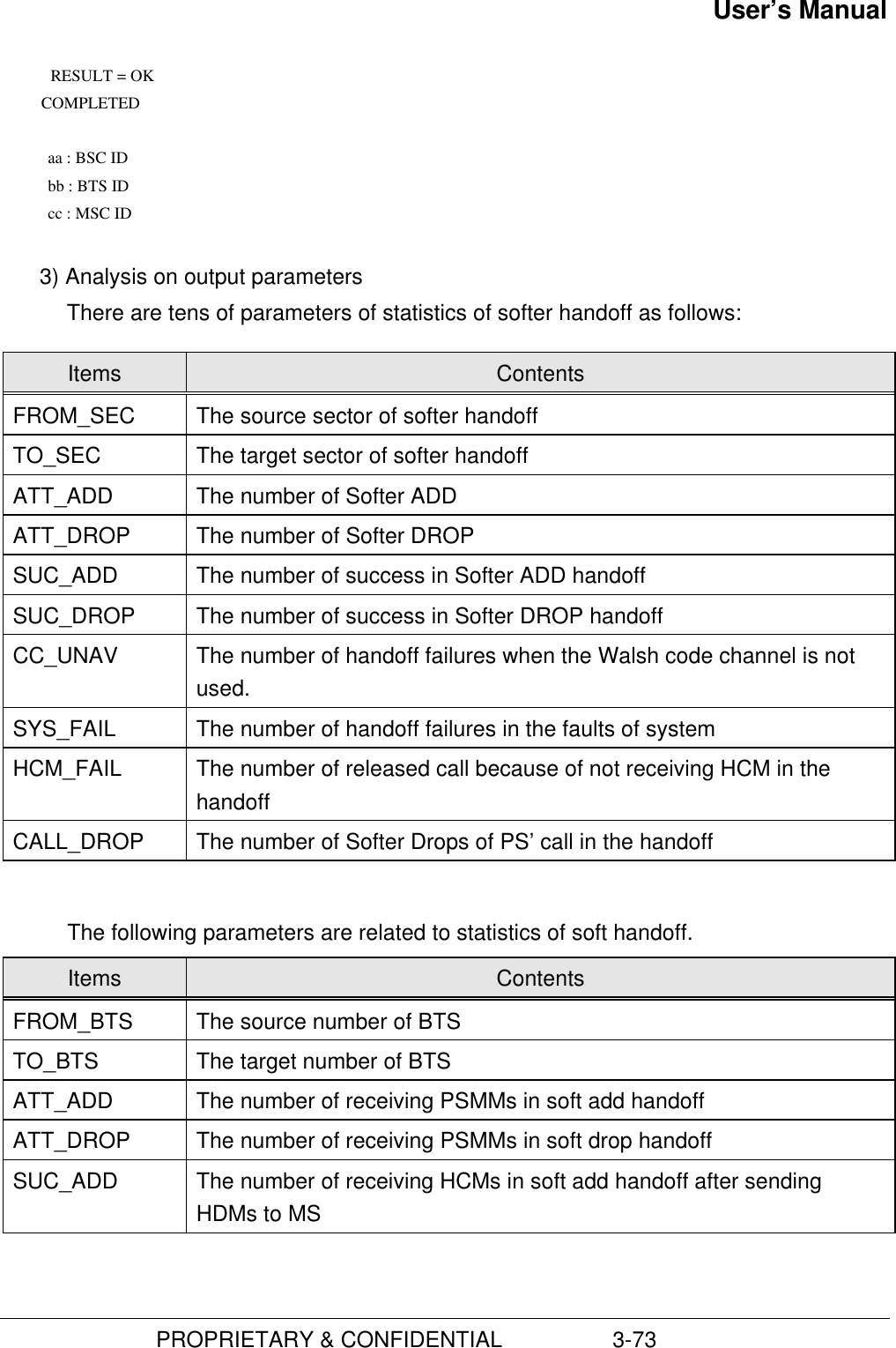
![User’s Manual PROPRIETARY & CONFIDENTIAL 3-71A_SUCC_% Call originated success rate(3) Statistics of Hand-offThere are three types of measurement and statistics : softer, soft, and Hard hand-off.Hard hand-off has three types : Intra-HHO, Inter-HHO, and Intra-Cell.1) You use the following command to start the statistics of hand-off.C6103 STRT-STAT-HDOF:[BSC=a,[BCP=b,]]ITEM=c,MPRD=d,MTIM=e;a : BSC Id (0 ~ 6)b : BCP Id (0 ~ 5)c : Statistic item of Handoff (HHO|SHO|RHO|ALL)d : Measurement Period (MIN10|HALF|HOUR)e : Measurement Times (1 ~ 50)System displays the “ACCEPTED” message.Ÿ Gathering the data of statistics starts the absolute time on 10, 20, 30, 40, 50,and 00 .2) As soon as the operators request statistics, the data of statistics are accumulated.Whenever the given periodic time (relative time 10, 30 and 60 minutes) is returned,these data displays the following message within 10 minutes every hour. - In case of Softer Handoff M6103 STATISTICS ON HANDOFF ITEM = HO_SOFTER DATE = YY-MM-DD HH:MM ~ HH:MM BSC_ID = aa BTS_ID FR_SEC TO_SEC ATT_ADD ATT_DRP SUC_ADD SUC_DRP CC_UNAV SYS_FLT HCM_FAIL CALL_DRP A_SUCC_% bb c c x x x x x x x x x ... RESULT = OK COMPLETED aa : BSC ID bb : BTS ID c : SECTOR ID](https://usermanual.wiki/Hyundai-Electronics-Co/HD-MIC1900/User-Guide-48794-Page-115.png)
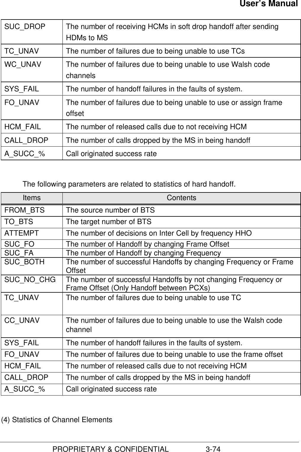
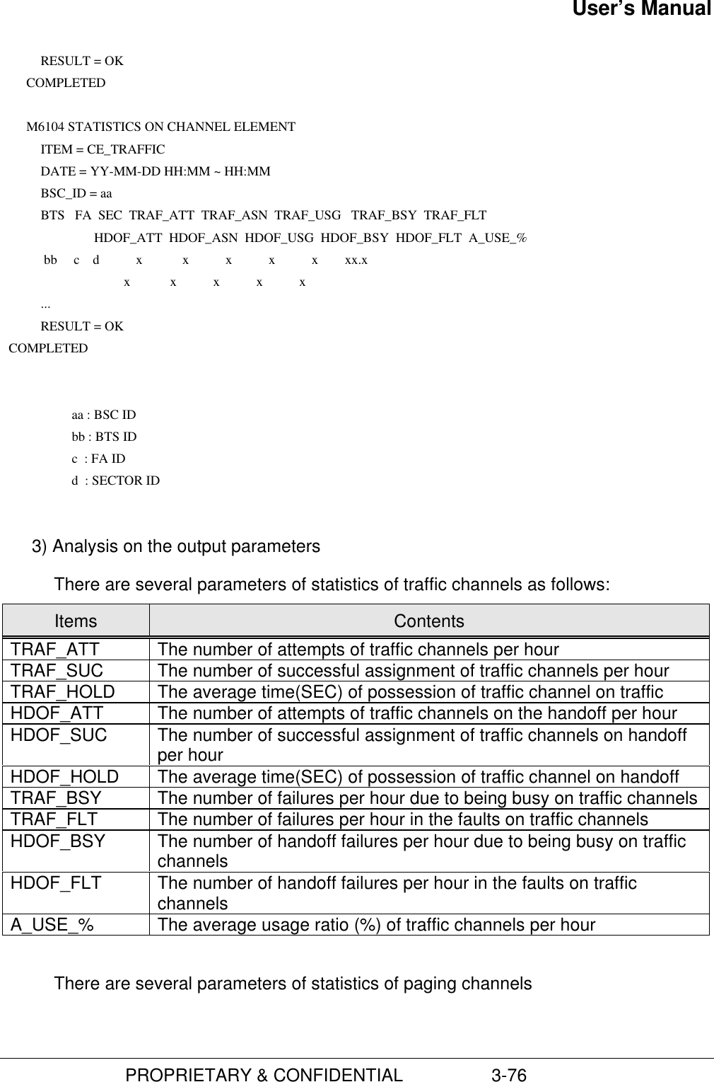
![User’s Manual PROPRIETARY & CONFIDENTIAL 3-75This statistics are measured by sector of BTS.1) Using the following command, you can start to the statistics of the channelelements.C6104 STRT-STAT-CE:[BSC=a,[BCP=b,]]MPRD=c,MTIM=d;a : BSC ID ( 0 - 6 )b : BCP ID ( 0 - 5 )c : Channel Element Statistic ITEM ( ACE/PCE/TCE/ALL)d : Measurement Periodical Time ( MIN10/HALF/HOUR )e : Measurement Times ( 1 - 50 )System displays the “ACCEPTED” message.• Gathering the data of statistics starts the absolute time on 10, 20, 30, 40, 50,and 00.2) As soon as the operators request statistics, the data of statistics are accumulated.Whenever the given periodic time (relative time 10, 30 and 60 minutes) is returned,these data displays the following message within 10 minutes every hour. M6104 STATISTICS ON CHANNEL ELEMENT ITEM = CE_ACCESS DATE = YY-MM-DD HH:MM ~ HH:MM BSC_ID = aa BTS FA AC_EQUIP AC_MX_LD AC_M_CNT AC_LD_RT bb c x x x x ... RESULT = OK COMPLETED M6104 STATISTICS ON CHANNEL ELEMENT ITEM = CE_PAGE DATE = YY-MM-DD HH:MM ~ HH:MM BSC_ID = aa BTS FA PC_EQUIP PC_MX_LD PC_M_CNT PC_LD_RT bb c x x x x ...](https://usermanual.wiki/Hyundai-Electronics-Co/HD-MIC1900/User-Guide-48794-Page-119.png)
![User’s Manual PROPRIETARY & CONFIDENTIAL 3-77Items ContentsAC_EQUIP The number of access channels equippedAC_MX_LD The maximum number of messages to be processed in the accesschannelsAC_M_CNT The number of messages actually processedAC_LD_RT The number of messages per unit time (second)There are four output parameters of statistics of paging channels as follows:Items ContentsPC_EQUIP The number of paging channels equippedPC_MX_LD The maximum number of messages to be processed in the pagingchannelsPC_M_CNT The number of messages actually processedPC_LD_RT The number of messages per unit time (second)(5) Statistics of vocoders1) Using the following command, you can start to the statistics of vocodersC6105 STRT-BTS-VOC:[BSC=a,[SIP=b,]]MPRD=c,MTIM=d;a : BSC ID (0 ~ 6)b : SIP ID (0 ~ 31)c : Measurement Period (MIN10|HALF|HOUR) d : Measurement Times (1 ~ 50)System displays the “ACCEPTED” message.Ÿ Gathering the data of statistics starts the absolute time on 10, 20, 30, 40, 50,and 00.2) As soon as the operators request statistics, the data of statistics are accumulated.Whenever the given periodic time (relative time 10, 30 and 60 minutes) is returned,these data displays the following message within 10 minutes every hour.](https://usermanual.wiki/Hyundai-Electronics-Co/HD-MIC1900/User-Guide-48794-Page-121.png)
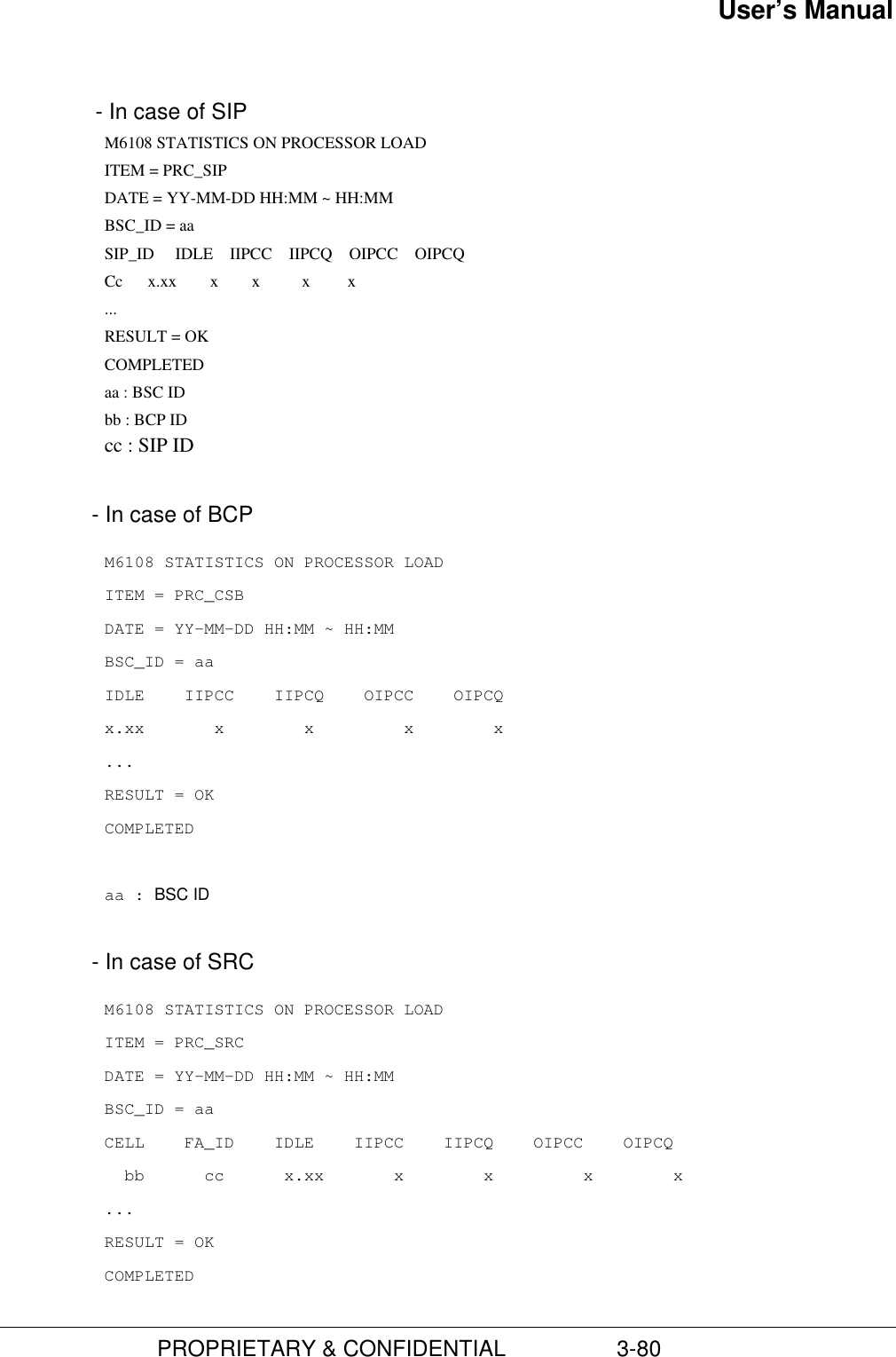
![User’s Manual PROPRIETARY & CONFIDENTIAL 3-78 M6105 STATISTICS ON VOCODER ITEM = VOC DATE = YY-MM-DD HH:MM ~ HH:MM BSC_ID = aa SIP_ID SVP_ID TX_A_B_R RX_A_B_R DURATION LOAD_DSP TOTAL_FRM FRM_B_ERR FRM_DELAY FRM_ERR_% BIT_ERR_% FRM_DLY_% bb cc x x x x x x x x x x ... RESULT = OK COMPLETED aa : BSC ID bb : SIP ID cc : SVP ID 3) Analysis on the output parametersThere are some parameters of statistic of vocoder (Tx/Rx) as follow:Items ContentsTX_BIT_RATE The average bit rate for sended frame (12.5 - 100%)RX_BIT_RATE The average bit rate for received frame (12.5 - 100%)AVG_LOAD_DSP The average load per a DSP (0 - 100%) : (AVG_DUR_TIME*100)/600AVG_DUR_TIME The average call state time (sec) : TOT_FRAME/(MAX_SVE_PER_SVP*50)FRAME_DELAY The number of frame that don’t receive from TCE each 20msFRM_B_BER The number of frame received from TCE having CRC or other errorsTOT_FRAME Total frame countAVG_FRM_ERR The average error frame to received frame (0 - 100%) :(FRM_B_ERR+FRM_DELAY)*100/TOT_FRAMEAVG_BIT_ERR The average error bit to received error frame (0 - 100%) :(FRM_B_ERR*100/(FRM_B_ERR+FRM_DELAY)FRM_DLY_RATE The average delay to received error frame (0 - 100%) :(FRM_B_ERR*100/(FRM_B_ERR+FRM_DELAY)(6) Statistics of Processors1) Using the following command, you can start to the statistics of processors.C6108 STRT-STAT-PRC : [BSC=a,][BCP=b,|SIP=c,|CSB=d,|SRC=e]ITEM=f,MPRD=g,MTIM=h;](https://usermanual.wiki/Hyundai-Electronics-Co/HD-MIC1900/User-Guide-48794-Page-122.png)
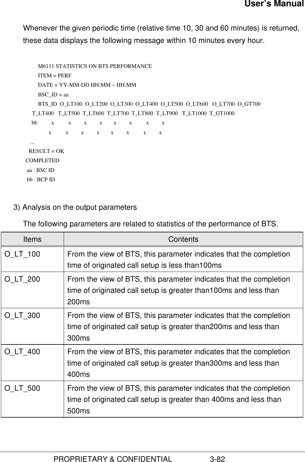
![User’s Manual PROPRIETARY & CONFIDENTIAL 3-81aa : BSC IDbb : CELL IDcc : FA ID3) Analysis on the output parametersThere are several output parameters of statistics of processors as follow:Items ContentsIDLE The average load of processorsIIPCC Input IPC Count (the number of Rx IPCc)OIPCC Output IPC Count (the number of Tx IPCs)IIPCQ Input IPC Quantity (the quantity of Rx IPC)OIPCQ Output IPC Quantity ( the quantity of Tx IPC)IN_IPCC The number of incoming IPCs in the CCP (only CCP)IN_IPCQ The quantity of incoming IPCs in the CCP (only CCP)MEM_USG CCP Processor Memory Usage Rate (only CCP)(6) Statistics of the performance of BTS1) Using the following command, you can start to the statistics of the performance ofBTS.C6111 STRT-STAT-PERF : [BSC=a,[BCP=b,]]MPRD=c,MTIM=d; a : BSC ID (0 ~ 6) b : BCP ID (0 ~ 5) c : Measurement Period (MIN10|HALF|HOUR) d : Measurement Times (1 ~ 50)System displays the “ACCEPTED” message.Ÿ Gathering the data of statistics starts the absolute time on 10, 20, 30, 40, 50,and 00.2) As soon as the operators request statistics, the data of statistics are accumulated.](https://usermanual.wiki/Hyundai-Electronics-Co/HD-MIC1900/User-Guide-48794-Page-125.png)
![User’s Manual PROPRIETARY & CONFIDENTIAL 3-84C6118 STRT-STAT-CAI : [BSC=a,[BCP=b,]]MPRD=c,MTIM=d; a : BSC ID (0 ~ 11)b : BCP ID (0 ~ 31)c : Report Item (BCP|TSB|ALL)d : Measurement Period (MIN10|HALF|HOUR)e : Measurement Times (1 ~ 50)System displays the “ACCEPTED” message.Ÿ Gathering the data of statistics starts the absolute time on 10, 20, 30, 40, 50,and 002) As soon as the operators request statistics, the data of statistics are accumulated.Whenever the given periodic time (relative time 10, 30 and 60 minutes) is returned,these data displays the following message within 10 minutes every hour. M6118 STATISTICS ON CAI SIGNALLING ITEM = CAI DATE = YY-MM-DD HH:MM ~ HH:MM BSC_ID = aa BTS_ID SEC_ID PC_EQUIP PC_PAGING P C_ORDER PC_CH_ASGN PC_DAT_BST PC_SER_RDR AC_EQUIP AC_MOB_ORG AC_REGIST AC_MOB_ORD AC_PAG_RSP AC_DAT_BST bb cc x x x x x x x x x x x x ... RESULT = OK COMPLETEDM6118 STATISTICS ON CAI SIGNALLINGITEM = TSB_CAIDATE = YY-MM-DD HH:MM ~ HH:MMBSC_ID = aaCELL SEC_ID FA_ID RCV_ORDER RCV_PSMM RCV_PMRM RCV_DTMF RCV_SVC_CON RCV_HDOF SND_ORDER SND_ALRT SND_NBOR SND_HDOF SND_SVC_CON bb cc dd x x x x xx x x x x x...](https://usermanual.wiki/Hyundai-Electronics-Co/HD-MIC1900/User-Guide-48794-Page-128.png)
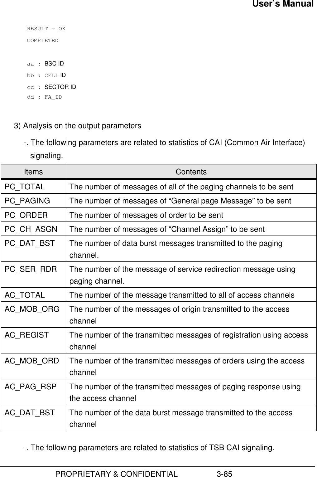
![User’s Manual PROPRIETARY & CONFIDENTIAL 3-86Items ContentsRCV_ORDER MS ACK Order, Release Order, Continous DTMF Order, etc.RCV_PSMM MS sends the messages measured Pilot to BS (ex., Pilot strength)RCV_PMRM MS sends the messages taken a statistics of forward link frame errorto BSRCV_DTMF MS sends the messages taken information when touchs the keypad toBSRCV_SVC_CON The response of “Service Connect Message”. Start its service.RCV_HDOF The complete report message updated for “Handoff Direction”SND_ORDER BS Ack Order, Release Order, Pilot Mesurement Request Order, etc.SND_ALRT Tone Off, Long Tone, RingBackTone On, etc.SND_NBOR Update the information of MS neighbor Pilot when MS does “Handoff”SND_HDOF Handoff Update Pilot Information messageSND_SVC_CON Allow the requested service (option)(8) Statistics of RFs1) You can start to the statistics of RF using the following command.C6107 STRT-STAT-RF:[BSC=a,[BCPS=b,]]MPRD=c,MTIM=d; a : BSC ID (0 ~ 6) b : BCP ID (0 ~ 5) c : Measurement Period (MIN10|HALF|HOUR) d : Measurement Times (1 ~ 50)System displays the “ACCEPTED” message.• Gathering the data of statistics starts the absolute time on 10, 20, 30, 40, 50, and002) As soon as the operators request statistics, the data of statistics are accumulated.Whenever the given periodic time (relative time 10, 30 and 60 minutes) is returned,these data displays the following message within 10 minutes every hour. M6107 STATISTICS ON BTS CHANNEL QUALITY ITEM = RF](https://usermanual.wiki/Hyundai-Electronics-Co/HD-MIC1900/User-Guide-48794-Page-130.png)
![User’s Manual PROPRIETARY & CONFIDENTIAL 3-87 DATE = YY-MM-DD HH:MM ~ HH:MM BSC_ID = aa BTS_ID SEC_ID AFWD_GAIN ARVS_GAIN OVF_FG_CNT bb c x x x ... RESULT = OK COMPLETED aa : BSC ID bb : BCP ID c : SECTOR ID 3) Analysis on the output parametersThe following parameters are related to statistics of radio frequency quality.Items ContentsAFWD_GAIN The average value of Tx gain of the forward channel for the forwardpower controlARVS_GAIN The average value of threshold of reverse channel for the reversepower controlOVF_FG_CNT The number of the arrived message of PMRM in spite of exceedingthe threshold of Max Tx Gain already for the forward power control.(9) Statistics of B-link1) Using the following command, you can start to the statistics of B linkC6106 STRT-STAT-LINK:[BSC=a,[BCP=b,]]MPRD=c,MTIM=d; a : BSC ID (0 ~ 6) b : BCP ID (0 ~ 5) c : Measurement Period (MIN10|HALF|HOUR) d : Measurement Times (1 ~ 50)System displays the “ACCEPTED” message.Ÿ Gathering the data of statistics starts the absolute time on 10, 20, 30, 40, 50, and002) As soon as the operators request statistics, the data of statistics are accumulated.](https://usermanual.wiki/Hyundai-Electronics-Co/HD-MIC1900/User-Guide-48794-Page-131.png)
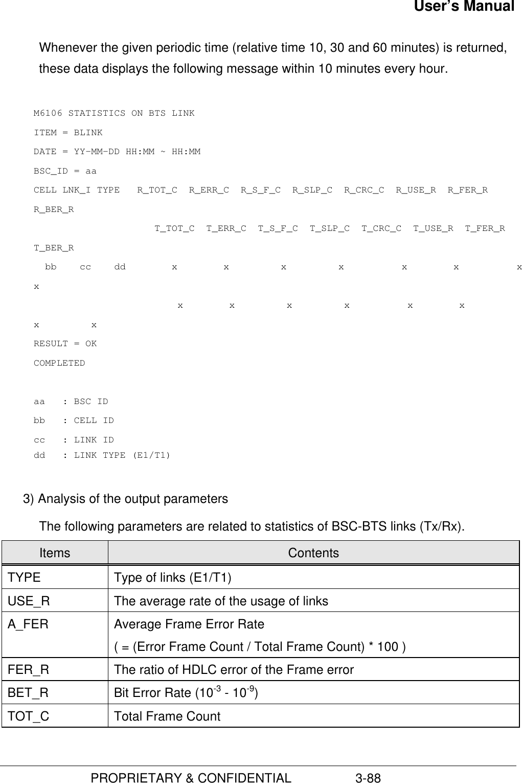
![User’s Manual PROPRIETARY & CONFIDENTIAL 3-89ERR_C Error Frame CountSLP_C Slip CountCRC_C CRC Count(10) Statistics of Faults1) Using the following command, you can start to the statistics of faults. C6109 STRT-STAT-FLT : [BSC=a,[BCP=b,] ITEM=c,MPRD=d,MTIM=e ; a : BSC ID (0 ~ 6) b : BCP ID (0 ~ 5) c : Fault Statistics Item d : Measurement Period (MIN10|HALF|HOUR) e : Measurement Times (1 ~ 50)System displays the “ACCEPTED” message.Ÿ Gathering the data of statistics starts the absolute time on 10, 20, 30, 40, 50, and002) As soon as the operators request statistics, the data of statistics are accumulated.Whenever the given periodic time (relative time 10, 30 and 60 minutes) is returned,these data displays the following message within 10 minutes every hour. - In case of BSC M6109 STATISTICS ON FAULT ITEM = FLT (BSC) DATE = YY-MM-DD HH:MM ~ HH:MM BSC_ID = aa CODE PWR PBA PRO CE OS LNK PLL CLK CBL OOS ENV Fxxxx x x x x x x x x x x x ... TOTAL = x RESULT = OK COMPLETED](https://usermanual.wiki/Hyundai-Electronics-Co/HD-MIC1900/User-Guide-48794-Page-133.png)
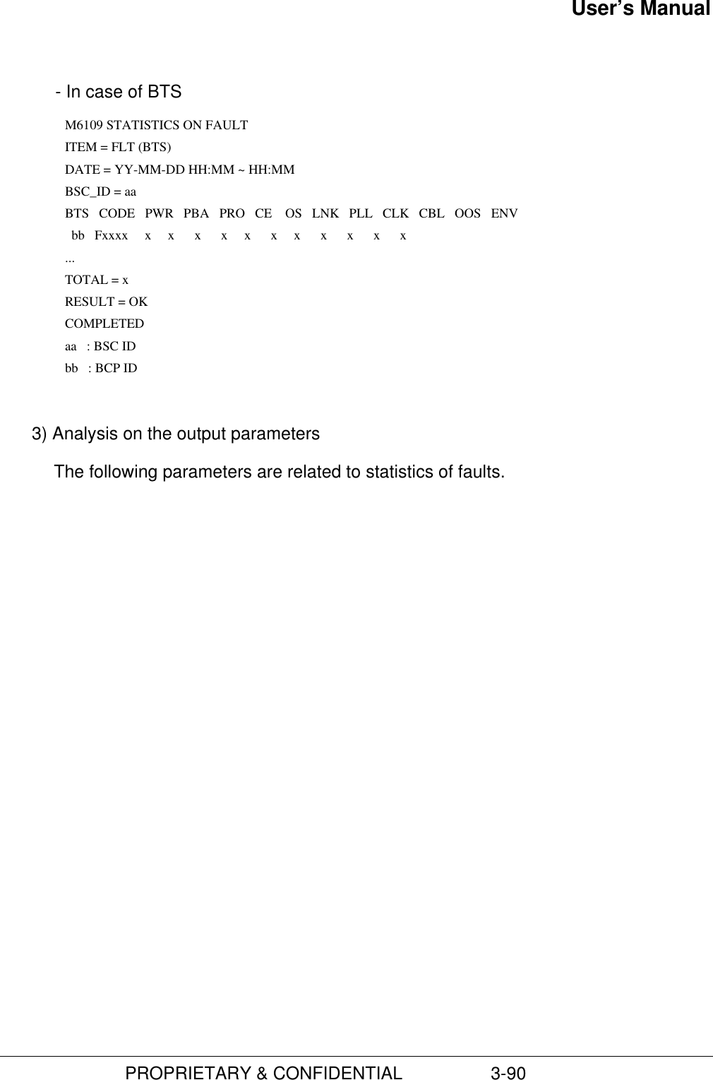
![User’s Manual PROPRIETARY & CONFIDENTIAL 3-91Items ContentsPWR The number of the occurrences of faults related to the powerPBA The number of the occurrences of faults related to the PBA boardsPRO The number of the occurrences of faults related to processorsCE The number of the occurrences of faults related to channel elementsOS The number of the occurrences of faults related to OSLNK The number of the occurrences of faults related to the linksPLL The number of the occurrences of faults related to PLLsCLK The number of the occurrences of faults related to clocksCBL The number of the occurrences of faults related to cablesOOS The number of the occurrences of faults related to out-of-servicesENV The number of the occurrences of faults related to the environment(11) Statistics of Alarms1) Using the following command, you can start to the statistics of alarms.C6110 STRT-STAT-ALM : [BSC=a,[BCP=b,]]ITEM=c,MPRD=d,MTIM=e ; a : BSC ID (0 ~ 6) b : BCP ID (0 ~ 5) c : Alarm Statistics Item d : Measurement Period (MIN10|HALF|HOUR) e : Measurement Times (1 ~ 50)System displays the “ACCEPTED” message.Ÿ Gathering the data of statistics starts the absolute time on 10, 20, 30, 40, 50,and 00.2) As soon as the operators request statistics, the data of statistics are accumulated.Whenever the given periodic time (relative time 10, 30 and 60 minutes) is returned,these data displays the following message within 10 minutes every hour.](https://usermanual.wiki/Hyundai-Electronics-Co/HD-MIC1900/User-Guide-48794-Page-135.png)
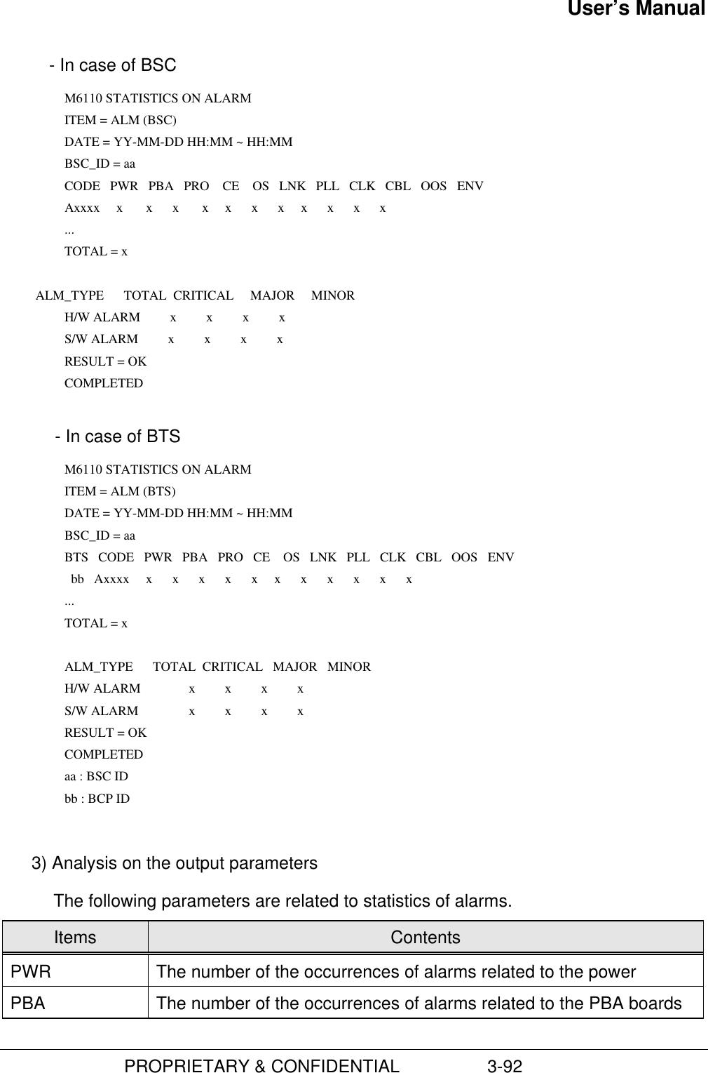
![User’s Manual PROPRIETARY & CONFIDENTIAL 3-93PRO The number of the occurrences of alarms related to the processorCE The number of the occurrences of alarms related to the channelelementsOS The number of the occurrences of alarms related to OSLNK The number of the occurrences of alarms related to the linksPLL The number of the occurrences of alarms related to PLLCLK The number of the occurrences of alarms related to the clocksCBL The number of the occurrences of alarms related to the cablesOOS The number of the occurrences of alarms related to the out-of-serviceENV The number of the occurrences of alarms related to the environment(12) Statistics of Paging1) Using the following command, you can start to the statistics of paging.C6112 STRT-STAT-PAG : [BSC=a,[BCP=b,]]MPRD=c,MTIM=d; a : BSC ID (0 ~ 6) b : BCP ID (0 ~ 5) d : Measurement Period (MIN10|HALF|HOUR) e : Measurement Times (1 ~ 50)System displays the “ACCEPTED” message.• Gathering the data of statistics starts the absolute time on 10, 20, 30, 40, 50, and002) As soon as the operators request statistics, the data of statistics are accumulated.Whenever the given periodic time (relative time 10, 30 and 60 minutes) is returned,these data displays the following message within 10 minutes every hour. M6112 STATISTICS ON PAGING ITEM = PAG DATE = YY-MM-DD HH:MM ~ HH:MM BSC_ID = aa BTS_ID ATT_1ST ATT_2ND RESPONSE NO_RESP bb x x x x](https://usermanual.wiki/Hyundai-Electronics-Co/HD-MIC1900/User-Guide-48794-Page-137.png)
![User’s Manual PROPRIETARY & CONFIDENTIAL 3-94 ... RESULT = OK COMPLETED aa : BSC ID bb : BCP ID 3) Analysis on the output parametersThe following parameters are related to statistics of paging.Items ContentsATT_1st The number of attempts of the first pagingATT_2nd The number of attempts of the second pagingRESPONSE The number of PS’s response for pagingNO_RESP The number of no responses for paging(13) Statistics of the Fault of RF in BTS1) Using the following command, you can start to the statistics of the Fault of RF inBTS.C6120 STRT-STAT-RFF : [BSC=a,[BCP=b,]]MPRD=c,MTIM=d; a : BSC ID (0 ~ 6)b : BCP ID (0 ~ 5)c : Measurement Period (MIN10|HALF|HOUR) e : Measurement Times (1 ~ 50)System displays the “ACCEPTED” message.Ÿ Gathering the data of statistics starts the absolute time on 10, 20, 30, 40, 50,and 00.2) As soon as the operators request statistics, the data of statistics are accumulated.Whenever the given periodic time (relative time 10, 30 and 60 minutes) is returned,these data displays the following message within 10 minutes every hour. M6120 STATISTICS ON RF PERFORMANCE ITEM = RF_FAULT](https://usermanual.wiki/Hyundai-Electronics-Co/HD-MIC1900/User-Guide-48794-Page-138.png)
![User’s Manual PROPRIETARY & CONFIDENTIAL 3-95 DATE = yy:mm:dd HH:MM ~ HH:MM BSC_ID = aa BTS FA SEC HPA LNA UP_BRD UP_PLL DN_BRD DN_PLL AGC bb d c x x x x x x x ... RESULT = OK COMPLETED aa : BSC ID bb : BCP ID c : SECTOR ID d : FA ID 3) Analysis on the output parametersThe following parameters are related to Statistics of the performance of RF in BTS.Items ContentsHPA The abnormal state of HPALNA The abnormal state of LNA(Low Noise Amplifier)UP_BRD The abnormal state of board of Up ConverterUP_PLL The abnormal state of PLL of Up ConverterDN_BRD The abnormal state of board of Down ConverterDN_PLL The abnormal state of PLL of Down converterAGC When the value of AGC(Automatic Gain Control) does not satisfy therange values, from –45 to –100 dBm, BSM gets the range valuesfrom RFC and then sends the measurement to BCP.(14) Statistics of Location Registration1) You can use the following command to start to the statistics of location registration.C6113 STRT-STAT-LR : [BSC=a,]MPRD=b,MTIM=c; a : BSC ID (0 ~ 6)b : Measurement Period (MIN10|HALF|HOUR)c : Measurement Times (1 ~ 50)System displays the “ACCEPTED” message.](https://usermanual.wiki/Hyundai-Electronics-Co/HD-MIC1900/User-Guide-48794-Page-139.png)
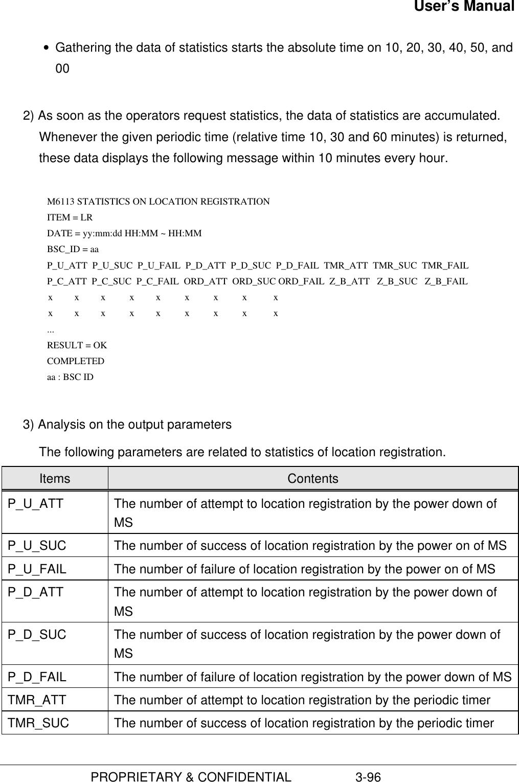
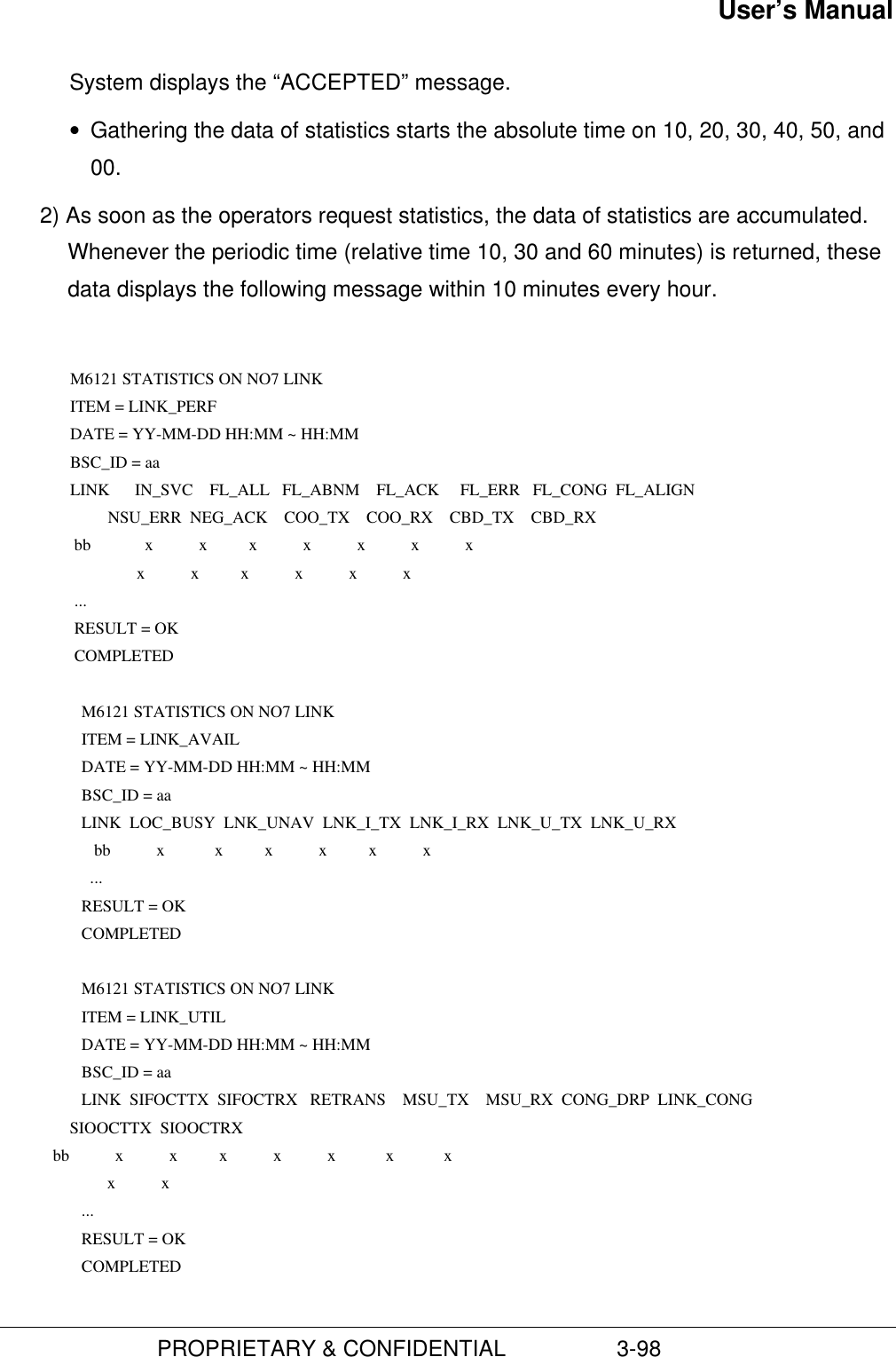
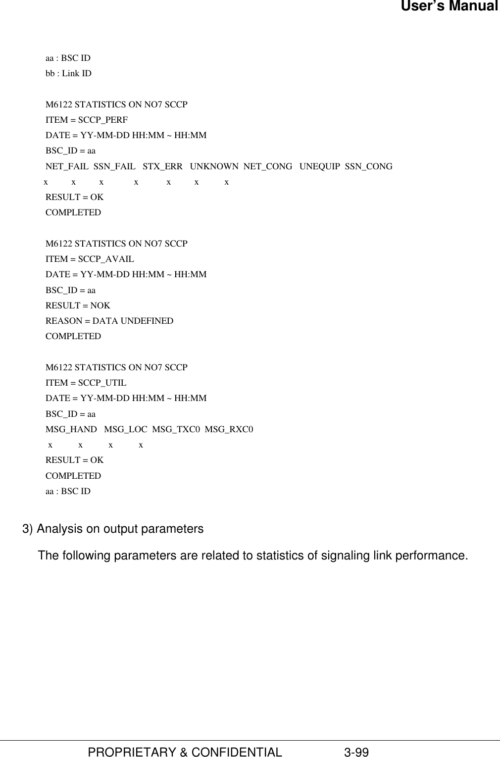
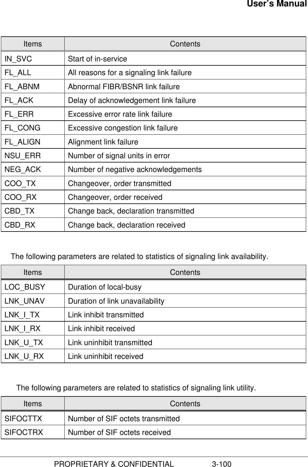
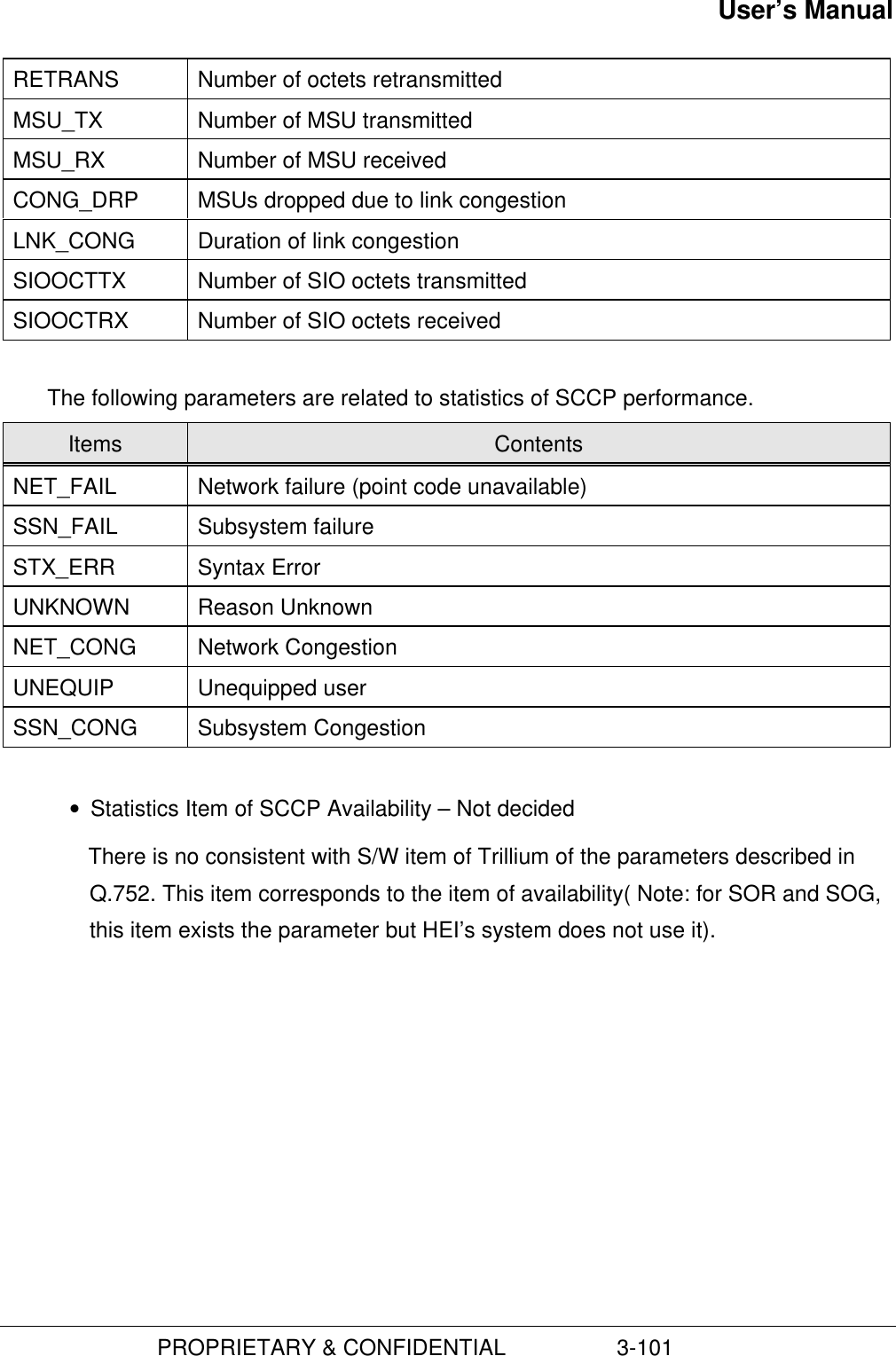
![User’s Manual PROPRIETARY & CONFIDENTIAL 3-97TMR_FAIL The number of failure of location registration by the periodic timerP_C_ATT The number of attempt to the location registration by the change ofparameters (SLOT_CYCLE_INDEX, SCM, and MOB_TERM)P_C_SUC The number of success of the location registration by the change ofparameters (SLOT_CYCLE_INDEX, SCM, and MOB_TERM)P_C_FAIL The number of failure of the location registration by the change ofparameters (SLOT_CYCLE_INDEX, SCM, and MOB_TERM)ORD_ATT The number of attempt to location registration by the command ofrequesting for it.ORD_SUC The number of success of location registration by the command ofrequesting for it.ORD_FAIL The number of failure of location registration by the command ofrequesting for it.Z_B_ATT The number of attempt to the location registration by the change ofzoneZ_B_SUC The number of success of location registration due to the change ofzone.Z_B_FAIL The number of failure of location registration due to the change ofzone(15) Statistics of No.71) You use the following command to start to the statistics of No.7.C6121 STRT-STAT-MTP:[BSC=a,]ITEM=b,MPRD=c,MTIM=d; a : BSC ID (0 ~ 6) b : Item (PERF|AVL|UTL|ALL) c : Measurement Period (MIN10|HALF|HOUR) d : Measurement Times (1 ~ 50) C6122 STRT-STAT-SCCP:[BSC=a,]ITEM=b,MPRD=c,MTIM=d; a : BSC ID (0 ~ 6) b : Item (PERF|AVL|UTL|ALL) c : Measurement Period (MIN10|HALF|HOUR) d : Measurement Times (1 ~ 50)](https://usermanual.wiki/Hyundai-Electronics-Co/HD-MIC1900/User-Guide-48794-Page-141.png)
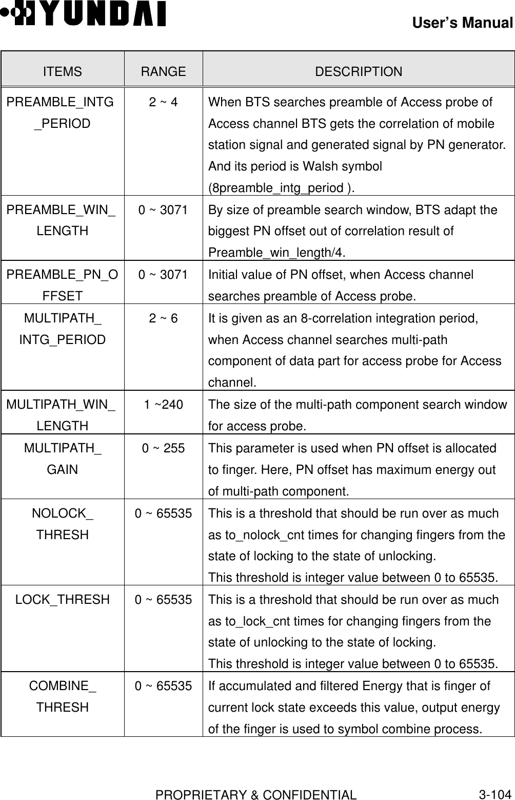
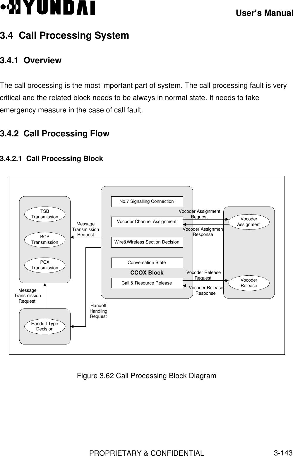
![User’s ManualPROPRIETARY & CONFIDENTIAL3-1033.3 Data ManagementThe Data is changed according to configuration or environment of BTS and BSC.Therefore, it is necessary to adjust as an appropriate value.3.3.1 Access Channel Parameter[ BSMcmd : xx ] DIS-AC-PARA:BTS=0,SECT=ALPHA,FA=0,PC=0;M5016 DISPLAY ACCESS CHANNEL PARAMETER BSC : 0 BCP : 0 BTS : 0 NAME : Grand SECTOR_ID : ALPHA CDMA_CH_INDEX : 0 PC_ID : 0 NUM_DEMODS : 4 PREAMBLE_INTG_PERIOD : 3 PREAMBLE_WIN_LENGTH : 1280 PREAMBLE_PN_OFFSET : 160 MULTIPATH_INTG_PERIOD : 6 MULTIPATH_WIN_LENGTH: 128 MULTIPATH_GAIN : 1 NOLOCK_THRESH : 63 LOCK_THRESH : 65 COMBINE_THRESH : 70ITEMS RANGE DESCRIPTIONSECTOR_ID 0 ~ 2 It is the Sector id number per BTS, and it sets on thebasis of 3 sectors.In case of the omni sector, SECTOR_ID is 0.CDMA_CH_INDEX Refer to 3.3.4 It is the CDMA series channel number per BTS, andconsists of CDMA frequency at BTS.Now, it accommodates the eight frequencies.PC_ID 0 ~ 6 It is a paging channel discrimination number, and itaccommodates 7 paging numbers per one sub-cell.NUM_DEMODS 1 ~ 4 The number of demodulator ASIC per channel.](https://usermanual.wiki/Hyundai-Electronics-Co/HD-MIC1900/User-Guide-48794-Page-147.png)
![User’s ManualPROPRIETARY & CONFIDENTIAL3-1053.3.2 Access Parameter[ BSMcmd : xx ] DIS-ACC-MSG:BTS=0,SECT=BETA,FA=0,PC=0;M5019 DISPLAY ACCESS PARAMETER MESSAGE BSC : 0 BCP : 0 BTS : 0 NAME : Grand SECTOR_ID : BETA CDMA_CH_INDEX : 0 PC_ID : 0 NORMINAL_PWR : 0 INITIAL_PWR : 0 PWR_STEP : 6 NUM_STEP : 6 MAX_CAP_SIZE : 0 PREAMBLE_SIZE : 3 PSIST_0_9 : 0 PSIST_10 : 0 PSIST_11 : 0 PSIST_12 : 0 PSIST_13 : 0 PSIST_14 : 0 PSIST_15 : 0 MSG_PSIST : 0 REG_PSIST : 0 PROBE_PN_RANDOM : 0 ACC_TIMEOUT : 5 PROBE_BACKOFF : 1 BACKOFF : 1 MAX_REQ_SEQ : 2 MAX_RSP_SEQ : 2 AUTH : NO RAND : 0 NOR_PWR_EXT : 0ITEMS RANGE DESCRIPTIONSECTOR_ID 0 ~ 2 Sector IDCDMA_CH_INDEX Refer to 3.3.4 CDMA channel index of BTSPC_ID 0 ~ 6 Paging channel IDNORMINAL_PWR -128 ~ 127 Nominal transmission power offset valueINITIAL_PWR -128 ~ 127 The initial power offset valuePWR_STEP 0 ~ 7 Power increment valueNUM_STEP 0 ~ 15 It has num_step+1 probes within an access probesequence.](https://usermanual.wiki/Hyundai-Electronics-Co/HD-MIC1900/User-Guide-48794-Page-149.png)
![User’s ManualPROPRIETARY & CONFIDENTIAL3-106ITEMS RANGE DESCRIPTIONMAX_CAP_SIZE 0 ~ 7 This parameter value is equal to[ Maximum frames of access channel messagecapsule in access channel slot - 1 ].PREAMBLE_SIZE 0 ~15 This parameter value is equal to[ Maximum frames of access channel preamble inaccess channel slot - 1 ].PSIST_0_9 0 ~ 63 This value is between 0 and 63 as persistence foroverload classes 0 ~ 9 ( commercial mobile system).PSIST_10 0 ~ 7 This value is between 0 and 7 as persistence foroverload classes 10 ( Emergency Use ).PSIST_11 0 ~ 7 This value is between 0 and 7 as persistence foroverload classes 11 ( Reserved ).PSIST_12 0 ~ 7 This value is between 0 and 7 as persistence foroverload classes 12 ( Reserved ).PSIST_13 0 ~ 7 This value is between 0 and 7 as persistence foroverload classes 13 ( Reserved ).PSIST_14 0 ~ 7 This value is between 0 and 7 as persistence foroverload classes 14 ( Reserved ).PSIST_15 0 ~ 7 This value is between 0 and 7 as persistence foroverload classes 15 ( Reserved ).MSG_PSIST 0 ~ 7 This value is between 0 and 7 as persistence formessage transmission.REG_PSIST 0 ~ 7 This value is between 0 and 7 as persistence forregistration.PROBE_PN_RANDOM0 ~ 9 When mobile station sends access probe to basestation, this is a random parameter for sending toaccess probe with random delay at access slot.ACC_TIMEOUT 2 ~ 63 After sending access probe, mobile station awaitsacknowledgment from base station duringacc_timeout.](https://usermanual.wiki/Hyundai-Electronics-Co/HD-MIC1900/User-Guide-48794-Page-150.png)
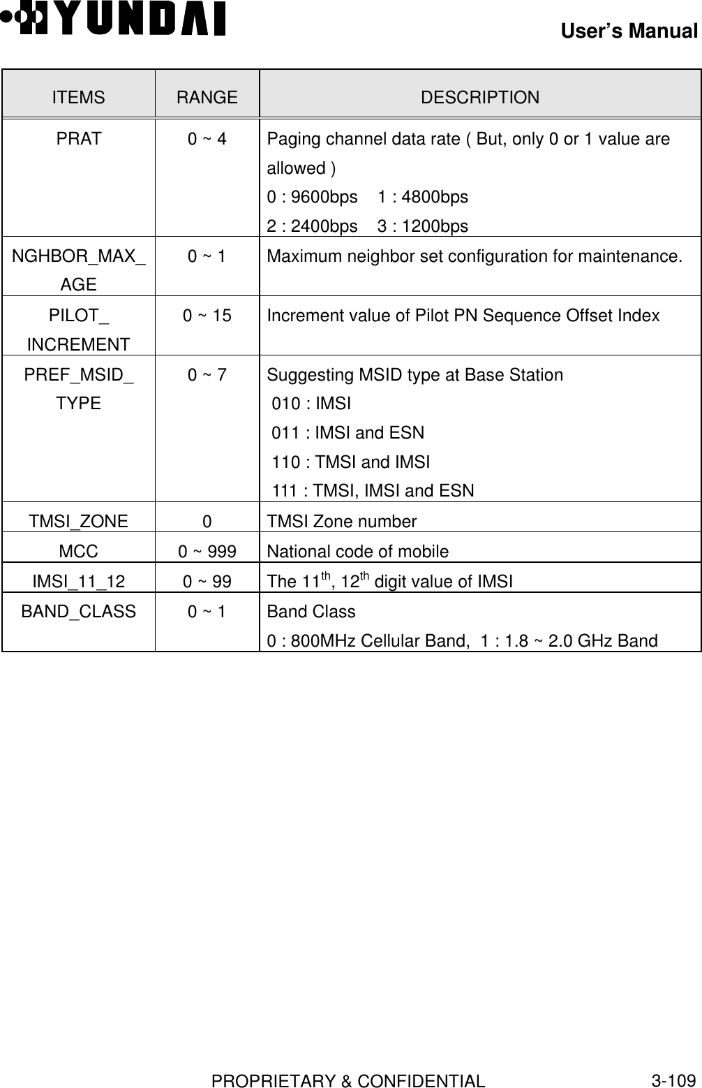
![User’s ManualPROPRIETARY & CONFIDENTIAL3-107ITEMS RANGE DESCRIPTIONPROBE_BACKOFF0 ~ 15 This is a backoff range between access probetransmission. ( After awaiting this period, mobilestation sends access probe sequence again. )BACKOFF 0 ~ 15 This is a backoff range between access probesequence.MAX_REQ_SEQ 1 ~ 15 Maximum value of access probe sequence aboutaccess channel request.MAX_RSP_SEQ 1 ~ 15 Maximum value of access probe sequence aboutaccess channel response.AUTH 0 ~ 1 Authentication mode00 : does not authentication process01 : does authentication process with randRAND 0 ~ 1 Random challenge numberIf AUTH is ‘00’, this parameter is omitted. If AUTH is“01”, this parameter have random number of 32 bit.NOR_PWR_EXT 0 ~ 1 Extended normal transmission power3.3.3 Information of BTS Configuration[ BSMcmd : xx ] DIS-BTS-CONF:BTS=0;M5000 DISPLAY BTS CONFIGURATION BSC : 0 BCP : 0 BTS : 0 NAME : Grand BTS_ID : 0 BTS_NAME : Grand EQP_STS : EQP BLK_STS : UBLK BTS_TYPE : SECTOR BASE_CLASS : PCS SID : 2222 NID : 4 NUM_CDMA_CH : 2 NUM_SECTOR : 3 REG_ZONE : 3 LTM_OFF : 18 DAY_LT : SAVING PRAT : 0(9600BPS) NGHBOR_MAX_AGE : 0 PILOT_INCREMENT : 2](https://usermanual.wiki/Hyundai-Electronics-Co/HD-MIC1900/User-Guide-48794-Page-151.png)

![User’s ManualPROPRIETARY & CONFIDENTIAL3-1113.3.4 Base Station CDMA Environment[ BSMcmd : xx ] DIS-FA-PARA:BTS=0;M5012 DISPLAY CDMA CHANNEL INDEX LIST BSC : 0 BCP : 0 BTS : 0 NAME : GrandCDMA_CH_INDEX CDMA_CH_ID CDMA_CH_KIND HANDOFF_TCE_RESERVE(%) 0 0 COMMON 0 1 1 COMMON 0ITEMS RANGE DESCRIPTIONCDMA_CH_INDEX 0 ~ (MAX_CDMA_CH_IDX -1) Maximum allowablefrequency IndexCDMA_CH_ID 0 ~ (MAX_CDMA_CH_IDX -1) Maximum allowablefrequency IDCDMA_CH_KIND 0 ~ 2 0:NO_SVC 1:COMMON2:UNIQUEHANDOFF_TCE_RESERVE 0 ~ 100 Reserve allowable rate( Percent )3.3.5 Base Station CDMA Information[ BSMcmd : xx ] DIS-CDMA-INFO;M5002 DISPLAY CDMA CHANNEL ID LIST CDMA_CH_ID CDMA_CH_NUM 0 350 1 250 2 65535 3 65535 4 65535 5 65535 6 65535](https://usermanual.wiki/Hyundai-Electronics-Co/HD-MIC1900/User-Guide-48794-Page-155.png)
![User’s ManualPROPRIETARY & CONFIDENTIAL3-112ITEMS RANGE DESCRIPTIONCDMA_CH_ID Refer to 3.3.4 The maximum allowable frequency IDCDMA_CH_NUM 1 ~ 1023 CDMA Channel Number corresponding to transmitfrequency.3.3.6 Base Station Channel List Message[ BSMcmd : xx ] DIS-CHLIST-MSG:BTS=0,SECT=BETA;M5090 DISPLAY CDMA CHANNEL LIST MESSAGE BTS : 0(Grand) SECTOR : BETA PILOT_PN : 120 CDMA_FREQ : 350 CDMA_FREQ : 250ITEMS RANGE DESCRIPTIONPILOT_PN 0 ~ 511 MS classified various signals from base station or sectorby offsets with basic PN code.CDMA_FREQ 1 ~ 1023 CDMA Channel Number corresponding to transmitfrequency.3.3.7 Extended System Parameter Information[ BSMcmd : xx ] DIS-EXTSYS-MSG:BTS=0,SECT=ALPHA,FA=0;M5089 DISPLAY EXTENDED SYSTEM PARAMETER MESSAGE BTS : 0(Grand) SECTOR : ALPHACDMA_CH_INDEX : 0 PILOT_PN : 100 PREF_MSID_TYPE : 3 MCC : 971 IMSI_11_12 : 0 TMSI_ZONE : 0 BCAST_INDEX : 0](https://usermanual.wiki/Hyundai-Electronics-Co/HD-MIC1900/User-Guide-48794-Page-156.png)
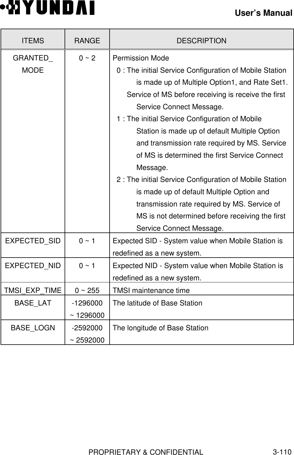
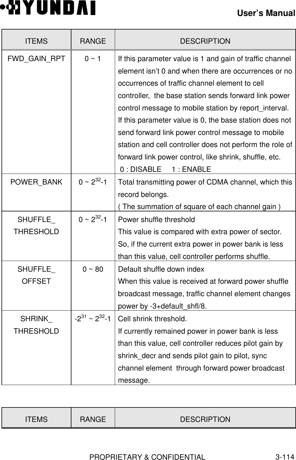
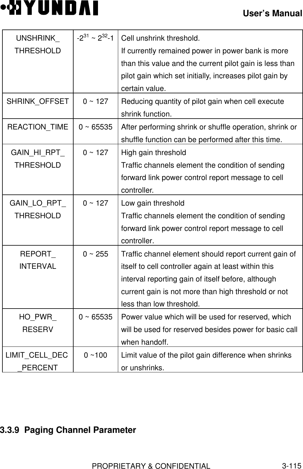
![User’s ManualPROPRIETARY & CONFIDENTIAL3-113ITEMS RANGE DESCRIPTIONPILOT_PN 0 ~ 511 MS classified various signals from base station orsector by offsets with basic PN codes.PREF_MSID_TYPE 2 ~ 7 Preferred Access Channel Mobile Station IdentifierType.MCC 0 ~ 999 National code of mobileIMSI_11_12 0 ~ 99 The 11th, 12th digit value of IMSITMSI_ZONE 0TMSI Zone numberBCAST_INDEX 0 orotherBroadcast slot cycle index ( 0 : disable, other : enable )3.3.8 Forward Link Power Information[ BSMcmd : xx ] DIS-FWDP-INFO:BTS=0,SECT=ALPHA,FA=0;M5013 DISPLAY FORWARD POWER DATA BSC : 0 BCP : 0 BTS : 0 NAME : Grand SECTOR_ID : ALPHA CDMA_CH_INDEX : 0 FWD_GAIN_RPT : DISABLE POWER_BANK : 8128 SHUFFLE_THRESHOLD : 0 SHUFFLE_OFFSET : 0 SHRINK_THRESHOLD : 0 UNSHRINK_THRESHOLD : 0 SHRINK_OFFSET : 0 REACTION_TIME : 800 GAIN_HI_RPT_THRESHOLD: 5 GAIN_LO_RPT_THRESHOLD : 5 REPORT_INTERVAL : 0 HO_PWR_RESERV : 0 LIMIT_CELL_DEC_PERCENT : 80ITEMS RANGE DESCRIPTIONSECTOR_ID 0 ~ 2 Sector IDCDMA_CH_INDEX Refer to 3.3.4 CDMA channel index of Base Station](https://usermanual.wiki/Hyundai-Electronics-Co/HD-MIC1900/User-Guide-48794-Page-157.png)
![User’s ManualPROPRIETARY & CONFIDENTIAL3-116[ BSMcmd : xx ] DIS-PC-PARA:BTS=0,SECT=ALPHA,FA=0,PC=0;M5018 DISPLAY PAGING CHANNEL PARAMETER BSC : 0 BCP : 0 BTS : 0 NAME : Grand SECTOR_ID : ALPHA CDMA_CH_INDEX : 0 PC_ID : 0 PC_GAIN : 65ITEMS RANGE DESCRITIONSECTOR_ID 0 ~ 2 Sector IDCDMA_CH_INDEX Refer to 3.3.4 CDMA channel index of BTSPC_ID 0 ~ 6 Paging channel discrimination number.One sub-cell has maximum 7 paging numbers.PC_GAIN 0 ~ 127 Paging channel gain value3.3.10 Psync Channel Parameter[ BSMcmd : xx ] DIS-PSC-PARA:BTS=0,SECT=ALPHA,FA=0;M5017 DISPLAY PILOT/SYNC CHANNEL PARAMETER BSC : 0 BCP : 0 BTS : 0 NAME : Grand SECTOR_ID : ALPHA CDMA_CH_INDEX : 0 PILOT_GAIN : 108 SYNC_GAIN : 34ITEMS RANGE DESCRIPTIONSECTOR_ID 0 ~ 2 Sector IDCDMA_CH_INDEX Refer to 3.3.4 CDMA channel index of BTSPILOT_GAIN 0 ~ 127 Pilot channel gain valueSYNC_GAIN 0 ~ 127 Sync channel gain value3.3.11 RFC Parameter](https://usermanual.wiki/Hyundai-Electronics-Co/HD-MIC1900/User-Guide-48794-Page-160.png)
![User’s ManualPROPRIETARY & CONFIDENTIAL3-117[ BSMcmd : xx ] DIS-RFC-PARA:BTS=0,SECT=BETA,FA=0;M5020 DISPLAY RADIO FREQUENCY CARD DATA BSC : 0 BCP : 0 BTS : 0 NAME : Grand SECTOR_ID : BETA CDMA_CH_INDEX : 0 RX_A_ATTEN : 0 RX_B_ATTEN : 0 TX_ATTEN : 0 FUNC_SWITCH : 0 NOISE_COUNT : 10 F_DECAY : 128 F_UPDATE_RATE : 100 RX_A_LOSS : 41 RX_B_LOSS : 41 K_SLOPE : 1 K_DELTA: 3 TX_GAIN_DELTA : 1 GEN_UPD_RATE : 200 PWR_TX_TIME : 1 DELTA_TX_ATTEN : 1 RCV_CALL_BLK_THR : 1 RCV_CALL_UBLK_THR : 1ITEMS RANGE DESCRIPTIONSECTOR_ID 0 ~ 2 Sector ID.CDMA_CH_INDEX Refer to 3.3.4 CDMA channel index of BTSRX_A_ATTEN 0 ~ 127 Attenuation of noise ( Reverse OUN ) added toreceiver A paths in 0.5dB steps from 0 to 63.5dB.Initial values of Rx A attenuator.RX_B_ATTEN 0 ~ 127 Attenuation of noise (Reverse OUN) added toreceiver B paths in 0.5dB steps from 0 to 63.5dB.Initial value of Rx B attenuator.TX_ATTEN 0 ~ 127 Transmission loss.So it is not used because there is no OUNS. Butthis is used as the meaning of attenuation level ofreceived signal for transmit path.ITEMS RANGE DESCRIPTION](https://usermanual.wiki/Hyundai-Electronics-Co/HD-MIC1900/User-Guide-48794-Page-161.png)

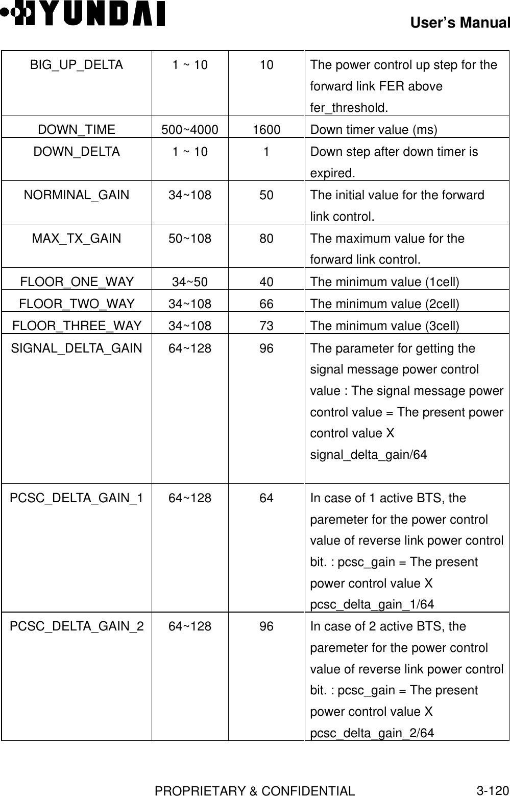
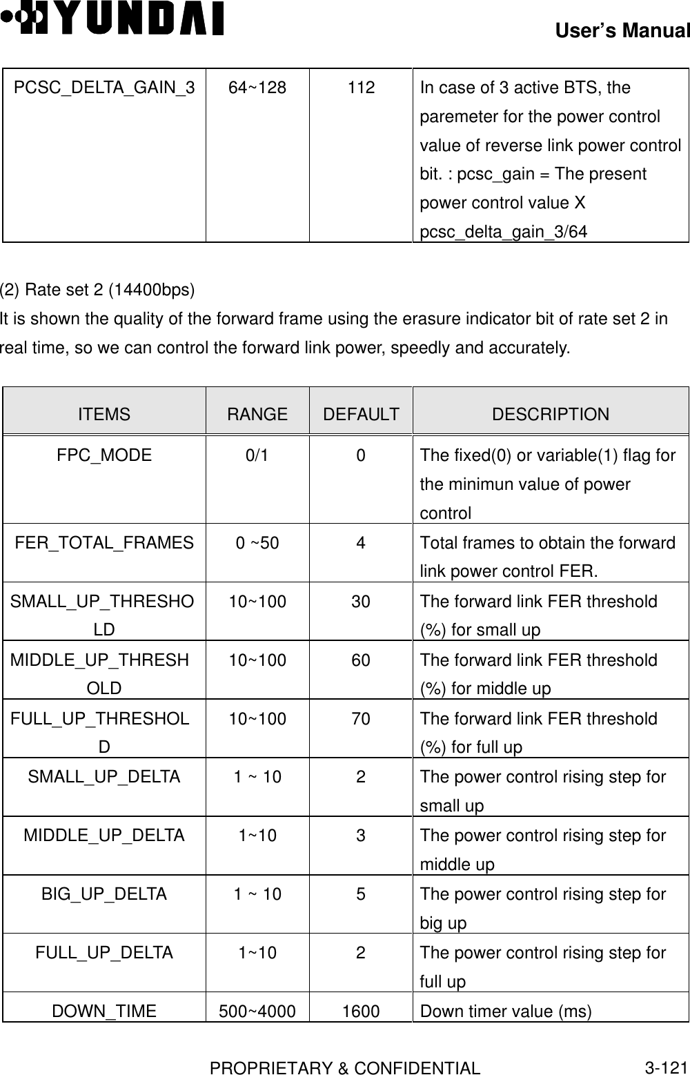
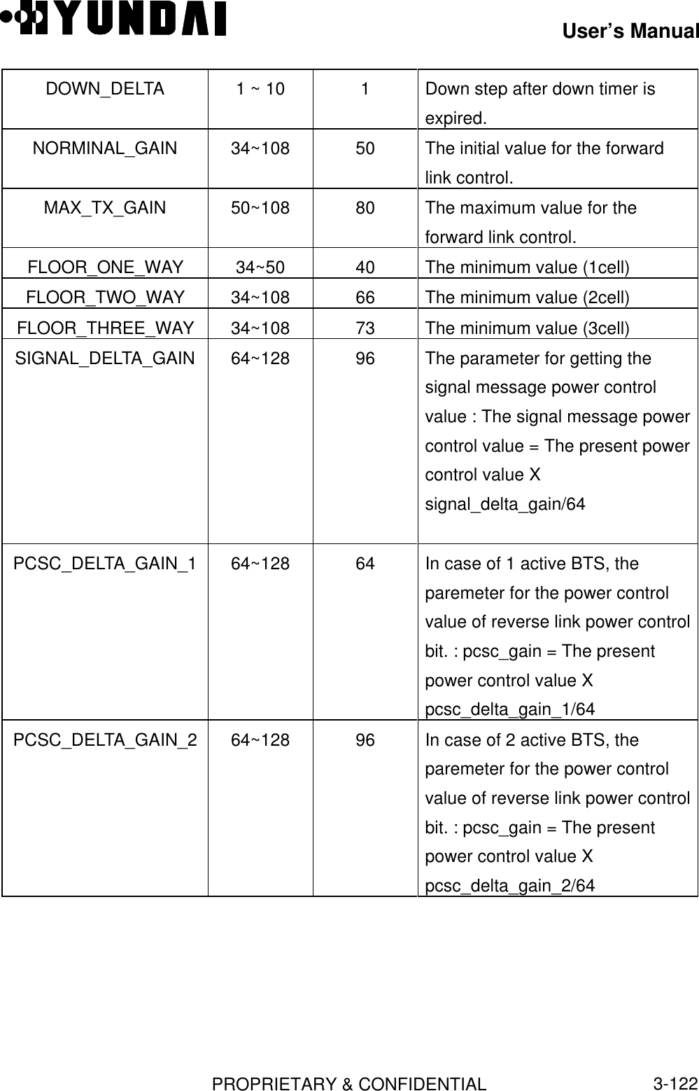
![User’s ManualPROPRIETARY & CONFIDENTIAL3-123PCSC_DELTA_GAIN_3 64~128 112 In case of 3 active BTS, theparemeter for the power controlvalue of reverse link power controlbit. : pcsc_gain = The presentpower control value Xpcsc_delta_gain_3/643.3.13 Reverse Link Power Control Data[ BSMcmd : xx ] DIS-RPC-INFO:BTS=0,SECT=GAMMA,FA=0;M5033 DISPLAY REVERSE POWER CONTROL DATA BSC : 0 BCP : 0 BTS : 0 NAME : Grand BTS_ID : 0 SECTOR_ID : GAMMA CDMA_CH_ID : 0 PWRCTL_NORMINAL : 26704 PWRCTL_MAX : 36408 PWRCTL_MIN : 15128 PWRCTL_UP_FULL : 3072 PWRCTL_UP_ERASURE : 248 PWRCTL_UP_ERASURE_LITTLE : 50 PWRCTL_DOWN : 32 PWRCTL_VAR_DOWN : 4 PWRCTL_FULL_WAIT : 1 PWRCTL_FULL_RUN_RESET : -2 PWRCTL_ERASURE_RUN_LIM : 5ITEMS RANGE DESCRIPTIONBTS_ID 0 ~ 511 Base Station IDSECTOR_ID 0 ~ 2 Sector IDCDMA_CH_ID Refer to 3.3.4 Base Station CDMA channel index](https://usermanual.wiki/Hyundai-Electronics-Co/HD-MIC1900/User-Guide-48794-Page-167.png)
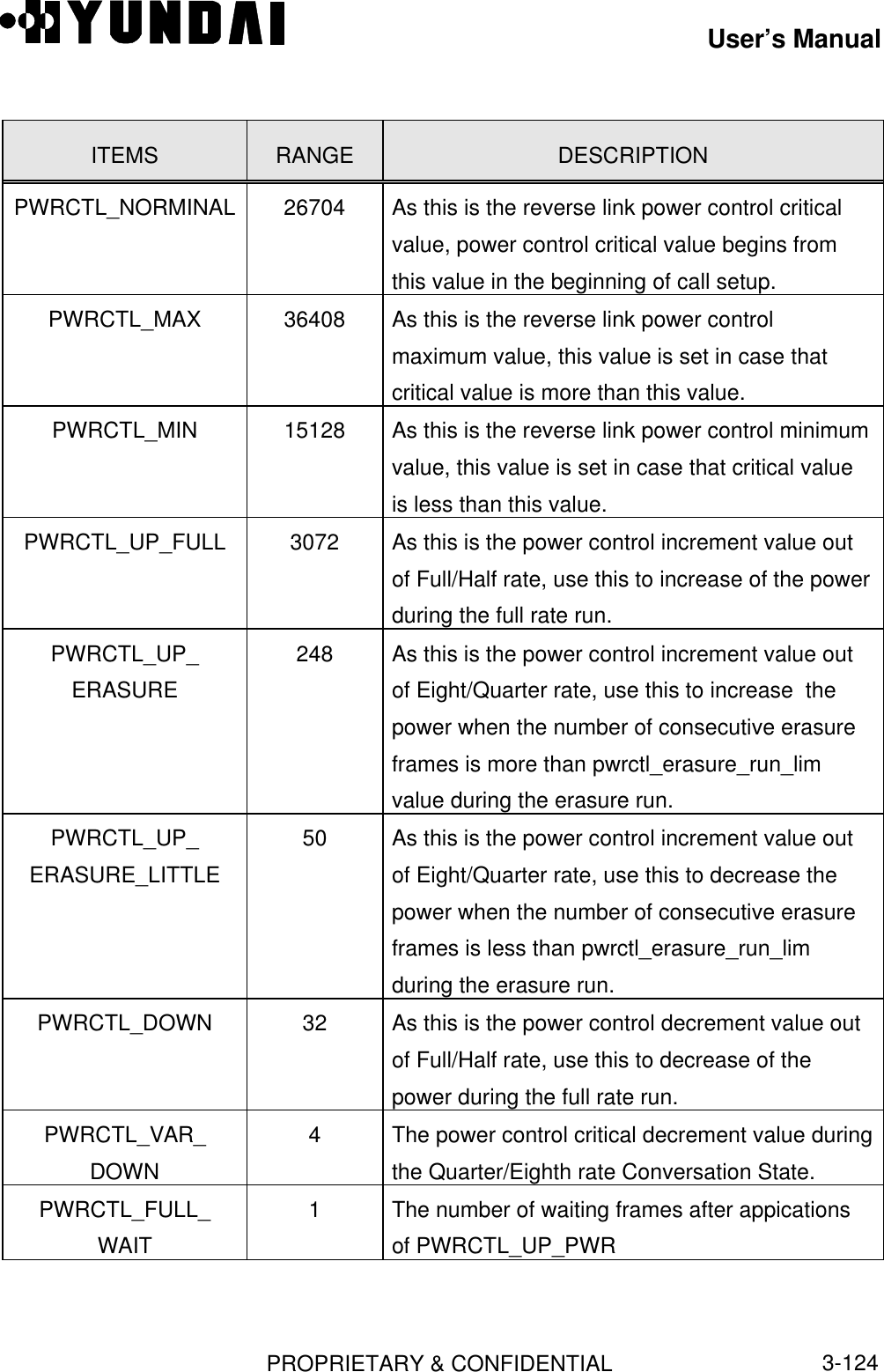
![User’s ManualPROPRIETARY & CONFIDENTIAL3-125ITEMS RANGE DESCRIPTIONPWRCTL_FULL_RUN_RESET-2 The minimum number of consecutive full/halfframes to to enter a full rate rate run.PWRCTL_ERASURE_RUN_LIM5Determine the increment amount of power by thisvalue, during the erasure run.3.3.14 Base Station Cell Information[ BSMcmd : xx ] DIS-SCEL-INFO:BTS=0,SECT=ALPHA,FA=0;M5004 DISPLAY SUBCELL CONFIGURATION BSC : 0 BCP : 0 BTS : 0 NAME : Grand BTS_ID : 0 SECTOR_ID : ALPHA CDMA_CH_ID : 0 SERVICE_ON_OFF : ON EQUIP_STATUS : EQP COMMON_PILOT_EQUIP : NEQP T_ADD : 28 T_DROP : 32 T_COMP : 5 T_TDROP : 2 SRCH_WIN_A : 6 SRCH_WIN_N : 7 SRCH_WIN_R : 8 PWR_REPT_THRESH : 3 PWR_REPT_FRAME : 7 PWR_THRESH_ENABLE : ENABLE PWR_PERIOD_ENABLE : ENABLE PWR_REPT_DELAY : 5ITEMS RANGE DESCRIPTIONBTS_ID 0 ~ 511 Base Station IDSECTOR_ID 0 ~ 2 Sector IDCDMA_CH_ID Refer to 3.3.4 CDMA channel IDSERVICE_ON_OFF 0 ~ 1 Service On/Off of corresponding to Subcell.( 0 : off, 1 : On )](https://usermanual.wiki/Hyundai-Electronics-Co/HD-MIC1900/User-Guide-48794-Page-169.png)
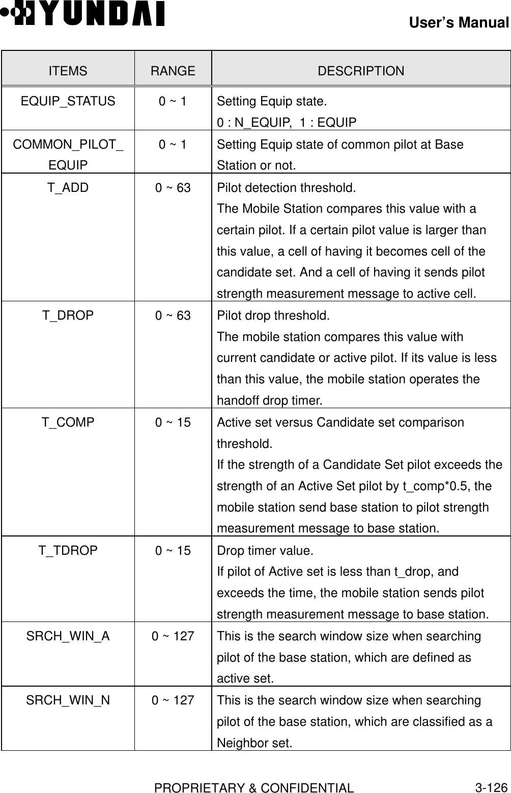
![User’s ManualPROPRIETARY & CONFIDENTIAL3-127ITEMS RANGE DESCRIPTIONSRCH_WIN_R 0 ~ 127 This is the search window size when searchingpilot of the base station, which are classified as aremaining set.PWR_REPT_THRESH0 ~ 31 If the bad frame numbers of forward frame exceedthis value, the mobile station sends PowerMeasurement Report Message to base station.PWR_REPT_FRAME0 ~ 31 If pwr_period_enable is ‘1’, mobile station sendsPower Measurement Report Message periodicallyto base station.PWR_THRESH_ENABLE0 ~ 1 If the power in mobile station exceedpwr_rept_thresh, mobile station sets PowerMeasurement Report Message to whether to sendor not to base station.0 : DISABLE, 1: ENABLEPWR_PERIOD_ENABLE0 ~ 1 This parameter is to set Power MeasurementReport Message whether to send or not to basestation from mobile station.0: DISABLE, 1 : ENABLEPWR_REPT_DELAY 0 ~ 31 This is the period that the mobile station do notcount received frame or bad frame after the mobilestation sends Power Measurement ReportMessage to base station.3.3.15 Corresponding Sector Information of BTS[ BSMcmd : xx ] DIS-SECT-INFO:BTS=0,SECT=BETA;M5001 DISPLAY SECTOR CONFIGURATION BSC : 0 BCP : 0 BTS : 0 NAME : Grand BTS_ID : 0 SECTOR_ID : BETA EQP_STS : EQP BLK_STS : UBLK](https://usermanual.wiki/Hyundai-Electronics-Co/HD-MIC1900/User-Guide-48794-Page-171.png)
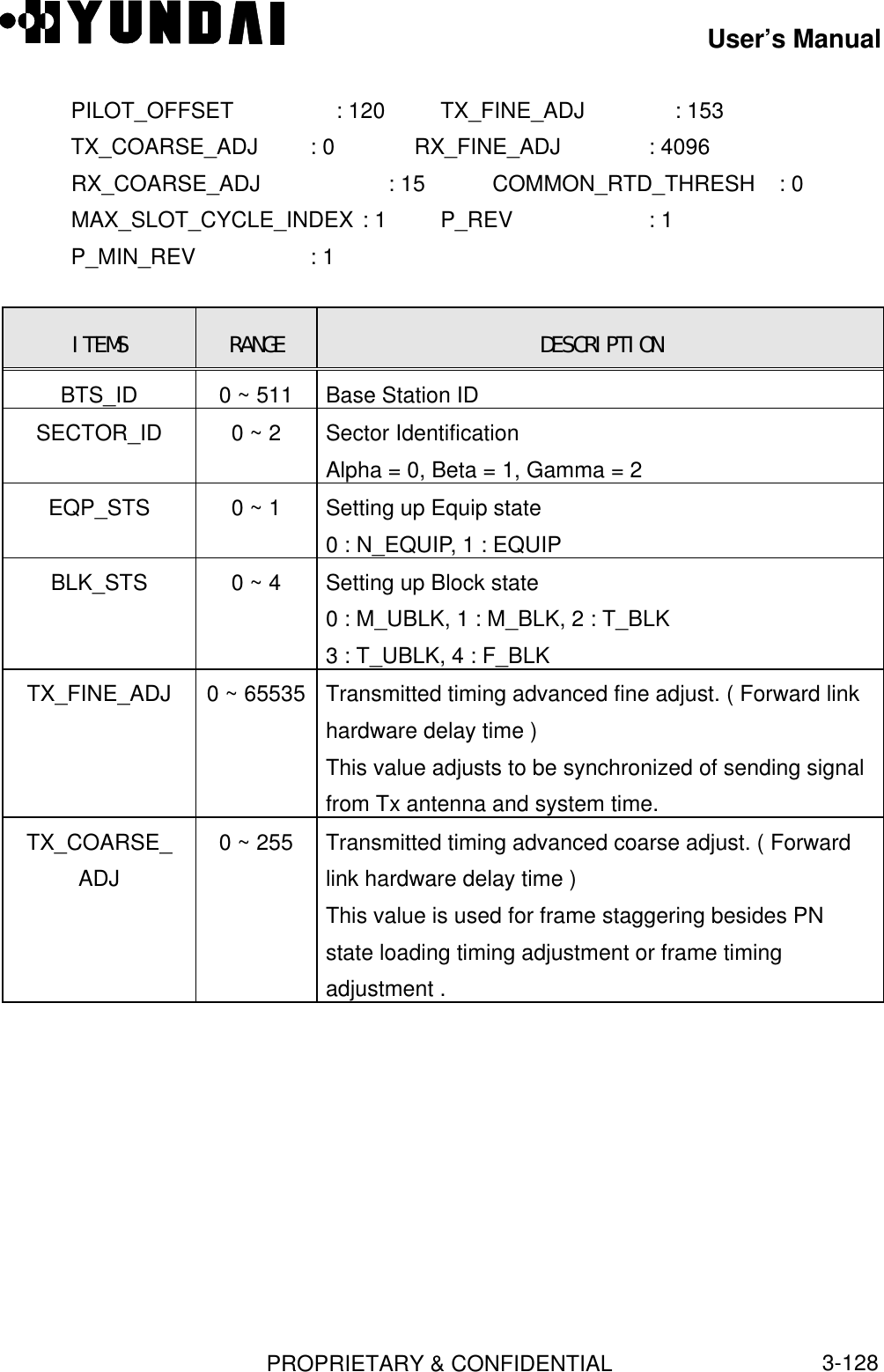
![User’s ManualPROPRIETARY & CONFIDENTIAL3-129ITEMS RANGE DESCRIPTIONRX_FINE_ADJ 0~ 65535 Receiver timing advanced fine adjust. ( Reverse linkhardware delay time )The frame boundary which is outputted fromDemodulator ASIC are delay more than system timebecause of signalling processing time such as symbolcombining.Therefore, the deinterleaver of modulator ASIC whichprocesses this output process signals on the basis offrame boundary equal to this output.This parameter is set to compensate delayed time.RX_COARSE_ADJ0 ~ 255 Receive timing advanced coarse adjust. ( Reverse linkhardware delay time )This value is used for frame staggering besidesdeinterleaver frame timing adjustment and framestaggering.COMMON_RTD_THRESH0 ~ ffffffff Threshold value of Round Trip Delay.MAX_SLOT_CYCLE_INDEX0 ~ 9 Maximum value of Slot Cycle Index.P_REV 0 ~ 7 Protocol Revision LevelP_MIN_REV 0 ~ 7 Protocol Minimum Revision Level3.3.16 Sync Channel Message[ BSMcmd : xx ] DIS-SYNC-MSG:BTS=0,SECT=BETA,FA=0;M5087 DISPLAY SYNC CHANNEL MESSAGE BTS : 0(Grand) SECTOR : BETA CDMA_CH_INDEX : 0 P_REV : 1 MIN_P_REV : 1 SID : 2222 NID : 4](https://usermanual.wiki/Hyundai-Electronics-Co/HD-MIC1900/User-Guide-48794-Page-173.png)
![User’s ManualPROPRIETARY & CONFIDENTIAL3-130 PILOT_PN : 120 LTM_OFF : 18 DAYLT : SAVING PRAT : 0(9600BPS) CDMA_FREQ : 350ITEMS RANGE DESCRIPTIONP_REV 0 ~ 7 Protocol Revision LevelP_MIN_REV 0 ~ 7 Protocol Minimum Revision LevelSID 0 ~ 32767 System ID NumberNID 0 ~ 65535 Network ID NumberPILOT_PN 0 ~ 511 Pilot PN offset of BTSLTM_OFF -24 ~ 24 Local time offset from UTCDAYLT 0 ~ 1 0 = standard time, 1 = Daylight saving time flagPRAT 0 ~ 4 Paging channel data rate ( Actually 0 or 1 allowed. )0 : 9600bps, 1 : 4800bps, 2 : 2400bps, 3 : 1200bpsCDMA_FREQ 1 ~ 1023 CDMA Channel Number corresponding totransmission frequency.3.3.17 System Parameter[ BSMcmd : xx ] DIS-SYS-PARA:BTS=0,SECT=GAMMA,FA=0;M5006 DISPLAY SYSTEM PARAMETER BSC : 0 BCP : 0 BTS : 0 NAME : Grand BTS_ID : 0 SECTOR_ID : GAMMA CDMA_CH_ID : 0 TOTAL_ZONES : 3 ZONE_TIMER : 3 HOME_REG : 1 FOR_NID_REG : 1 FOR_SID_REG : 1 POWER_UP_REG : 1 POWER_DOWN_REG : 1 PARAMER_REG : 1 REG_PERIOD : 02 MIN REG_DISTANCE : 0 RESCAN : 0 MULT_SIDS : 0](https://usermanual.wiki/Hyundai-Electronics-Co/HD-MIC1900/User-Guide-48794-Page-174.png)
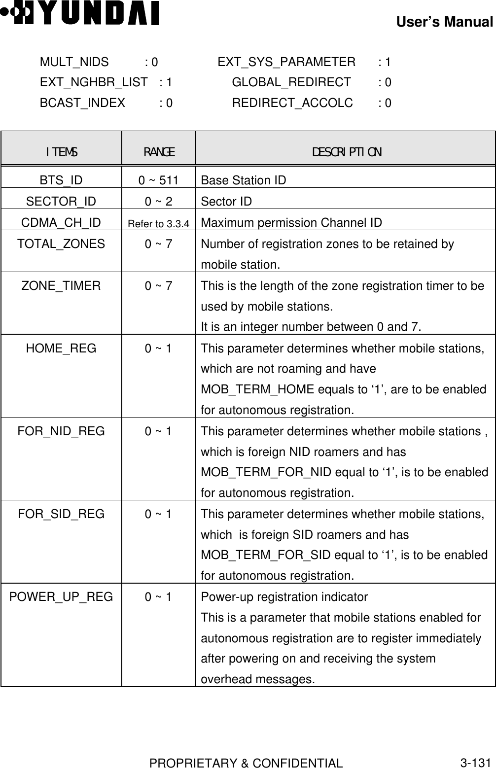
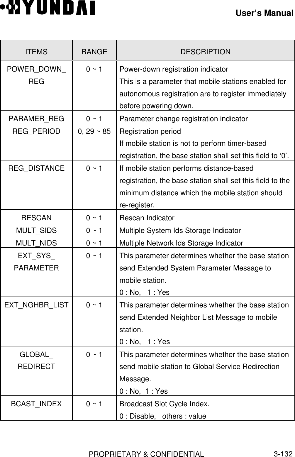
![User’s ManualPROPRIETARY & CONFIDENTIAL3-133ITEMS RANGE DESCRIPTIONREDIRECT_ACCOLC0 ~ 1 Redirected access overload classThis field is composed of subfield between ACCESSOVERLOAD CLASS 0 ( 1 Bit ) and ACCESSOVERLOAD CLASS 15.3.3.18 System Parameter Message[ BSMcmd : xx ] DIS-SYSPARA-MSG:BTS=0,SECT=BETA,FA=0;M5088 DISPLAY SYSTEM PARAMETER MESSAGE BTS : 0(Grand) SECTOR : BETA CDMA_CH_INDEX : 0 PILOT_PN : 120 SID : 2222 NID : 4 REG_ZONE : 3 TOTAL_ZONE : 3 ZONE_TIMER : 3 MULT_SIDS : 0 MULT_NIDS : 0 BASE_ID : 0 BASE_CLASS : 1 PAGE_CHAN : 1 MAX_SLOT_CYC_IDX : 1 HOME_REG : 1 FOR_SID_REG : 1 FOR_NID_REG : 1 POWER_UP_REG : 1 POWER_DOWN_REG : 1 PARAMETER_REG : 1 REG_PRD : 44 BASE_LAT : 0 BASE_LOGN : 0 REG_DIST : 0 SRCH_WIN_A : 6 SRCH_WIN_N : 7 SRCH_WIN_R : 8 NGHBR_MAX_AGE : 0 PWR_REP_THRESH : 3 PWR_REP_FRAMES : 7 PWR_THRESH_ENABLE : ENABLE PWR_PERIOD_ENABLE : ENABLE PWR_REP_DELAY : 5 RESCAN : 0 T_ADD : 28 T_DROP : 32 T_COMP : 5 T_TDROP : 2 EXT_SYS_PARAM : 1 EXT_NGHBR_LIST : 1 GLOBAL_REDIRECT : 0](https://usermanual.wiki/Hyundai-Electronics-Co/HD-MIC1900/User-Guide-48794-Page-177.png)
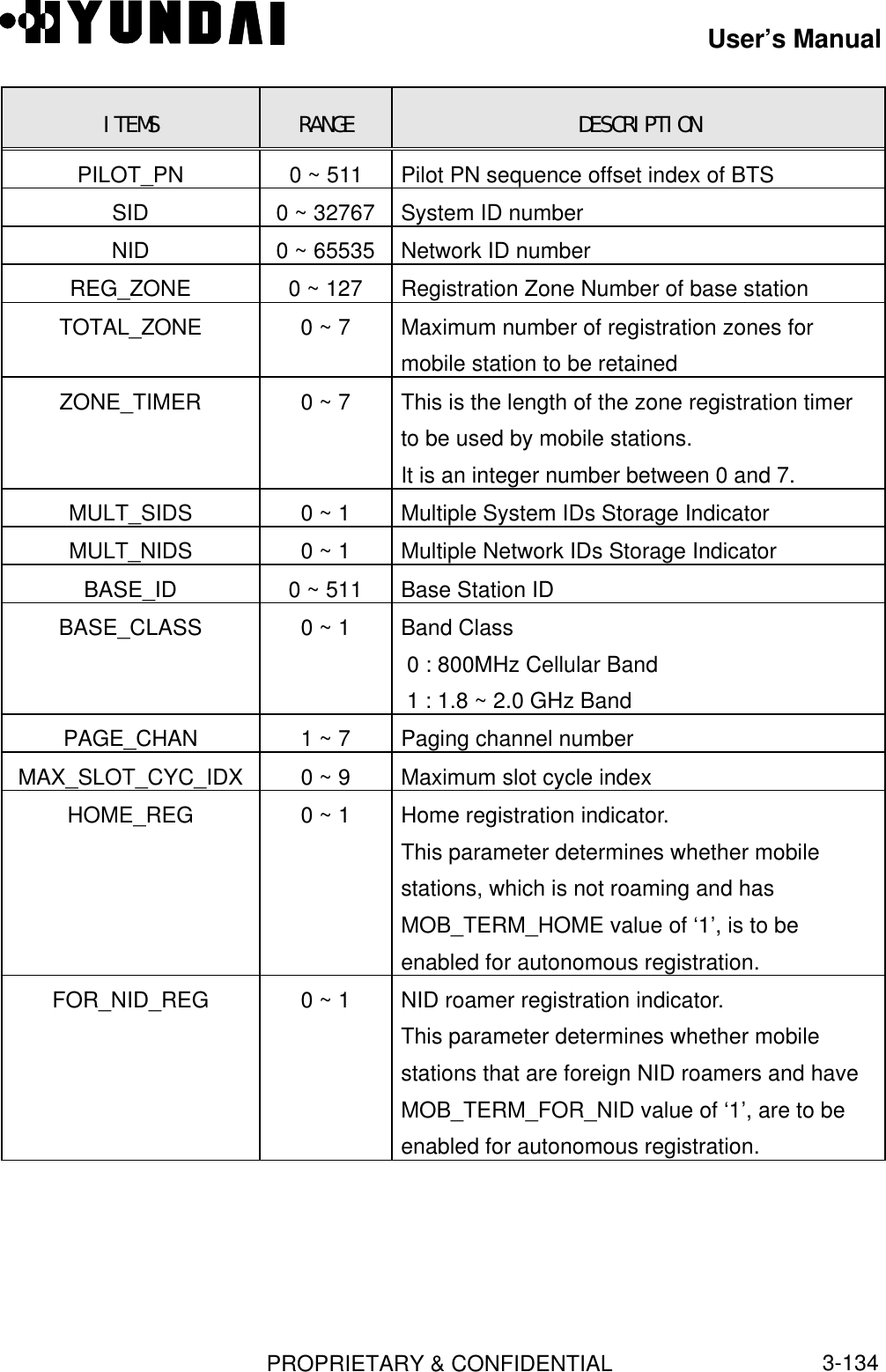
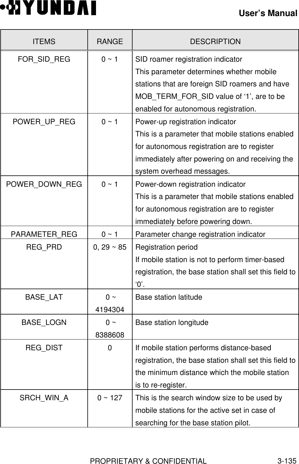
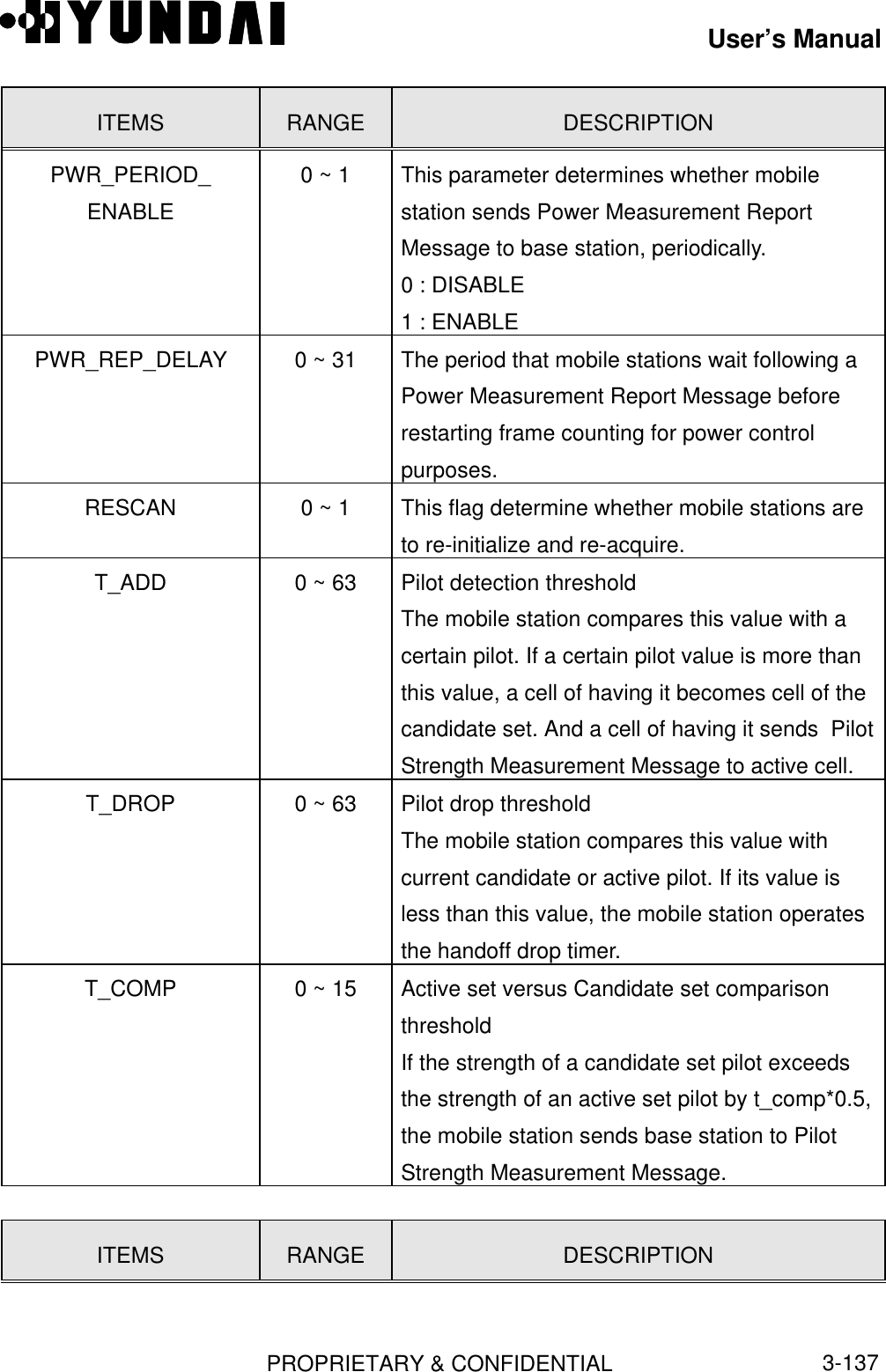
![User’s ManualPROPRIETARY & CONFIDENTIAL3-136ITEMS RANGE DESCRIPTIONSRCH_WIN_N 0 ~ 127 This is the search window size to be used bymobile stations for the neighbor set in case ofsearching for the base station pilot.SRCH_WIN_R 0 ~ 127 This is the search window size to be used bymobile stations for the remaining set in case ofsearching for the base station pilot.NGHBR_MAX_AGE 0 ~ 7 Set this field to the maximum AGE value whichmobile stations drop members from theNeighbor Set.PWR_REP_THRESH 0 ~ 31 Set this field to the number of bad frames to bereceived in a measurement period before mobilestations are to generate a Power MeasurementReport Message.PWR_REP_FRAMES 0 ~ 31 Set this field to the value such that the numbergiven by [ 2(PWR_REP_FRAMES) X 5 ] frames is thenumber of frames over which mobile stations areto count frame errors.If the pwr_period_enable is ‘1’, the mobilestation sends power measurement reportmessage to base station, each receiving acalculated frames.PWR_THRESH_ENABLE0 ~ 1 This parameter determines whether mobilestation sends power measurement message tobase station, when mobile station powerexceeds pwr_rep_thresh parameter value.0 : DISABLE1 : ENABLE](https://usermanual.wiki/Hyundai-Electronics-Co/HD-MIC1900/User-Guide-48794-Page-180.png)
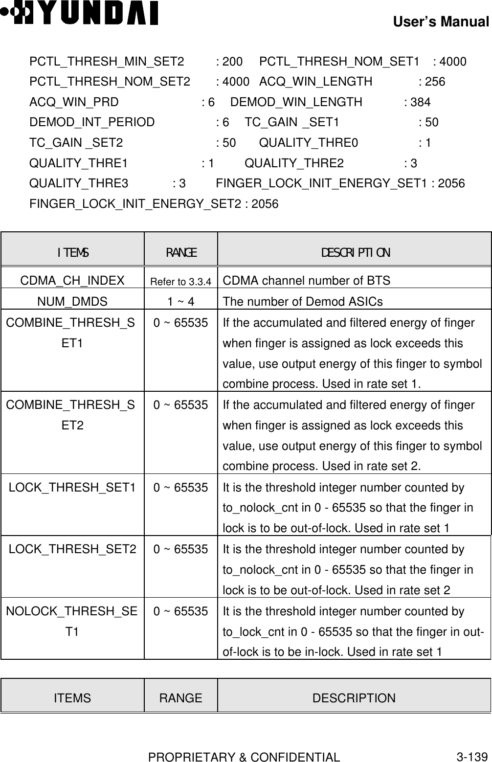
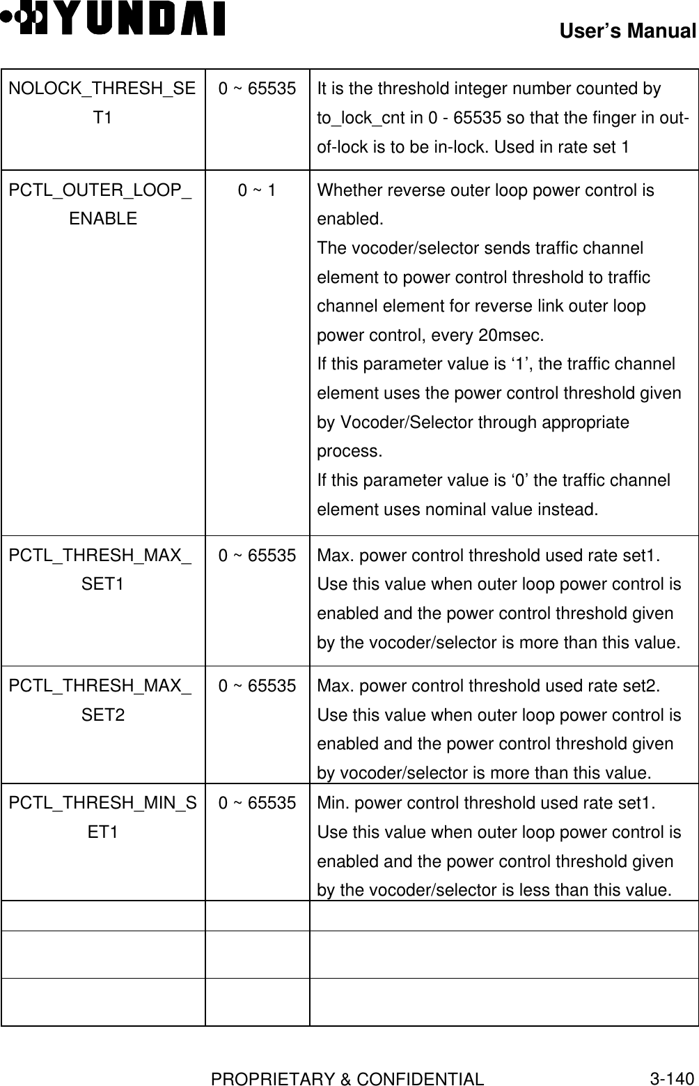
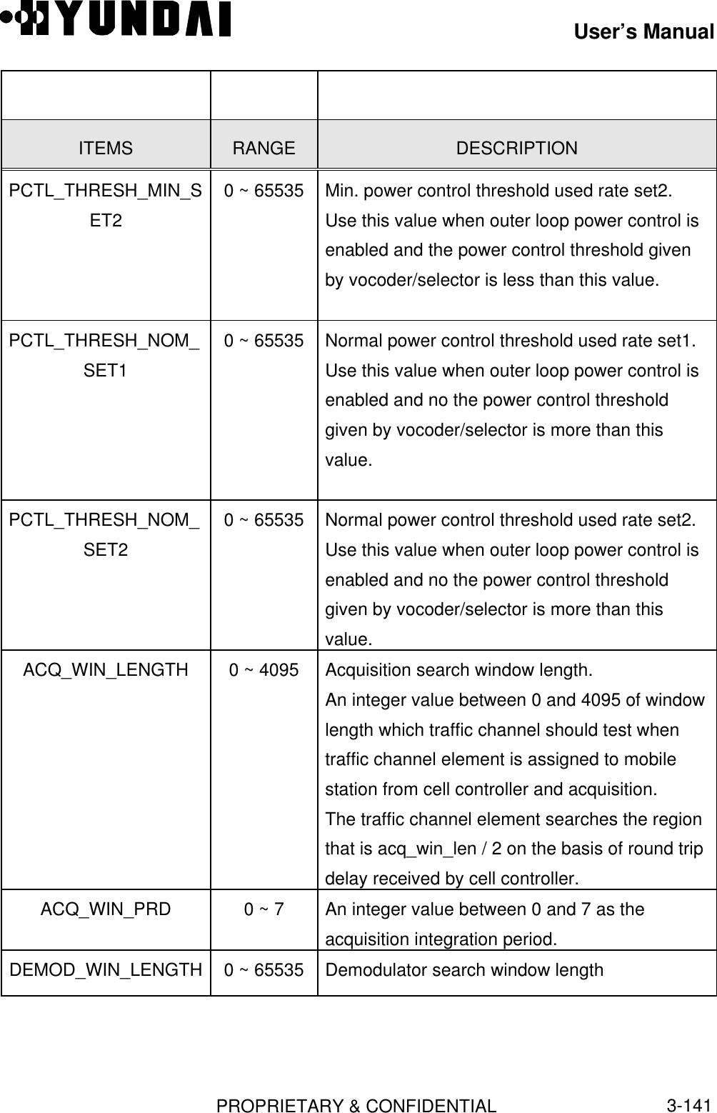
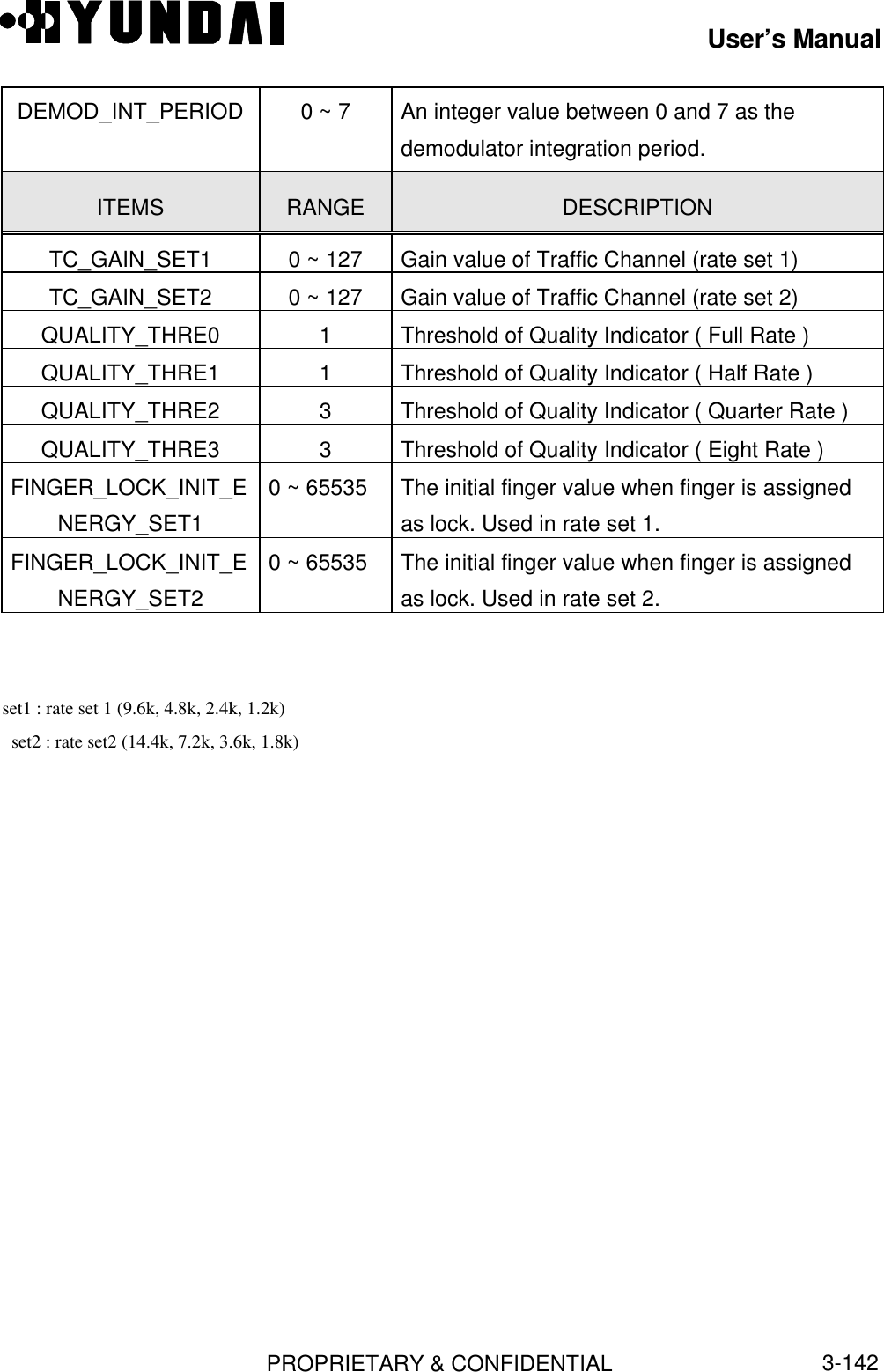
![User’s ManualPROPRIETARY & CONFIDENTIAL3-138T_TDROP 0 ~ 15 Drop timer value.While t_tdrop timer exceed, if the strength of anactive set pilot has not become greater thant_drop, the mobile station sends pilot strengthmeasurement message to base station.EXT_SYS_PARAM 0 ~ 1 This parameter determines whether the basestation sends Extended System ParameterMessage to mobile station. 0 : No 1 : YesEXT_NGHBR_LIST 0 ~ 1 This parameter determines whether the basestation sends Extended Neighbor List Messageto mobile station. 0 : No 1 : YesGLOBAL_REDIRECT 0 ~ 1 This parameter determines whether the basestation sends Global Service RedirectionMessage to mobile station. 0 : No 1 : Yes3.3.19 Traffic Channel Parameter[ BSMcmd : xx ] DIS-TC-PARA:BTS=0,FA=0;M5015 DISPLAY TRAFFIC CHANNEL PARAMETER BSC : 0 BCP : 0 BTS : 0 NAME : Grand CDMA_CH_INDEX : 0 NUM_DMDS : 4 COMBINE_THRESH_SET1 : 70 COMBINE_THRESH_SET2 : 70 LOCK_THRESH_SET1 : 2729 LOCK_THRESH_SET2 : 2739 NOLOCK_THRESH_SET1: 2729 NOLOCK_THRESH_SET2 : 2729PCTL_OUTER_LOOP_ENABLE : 1 PCTL_THRESH_MAX_SET1 : 7683PCTL_THRESH_MAX_SET2 : 7683 PCTL_THRESH_MIN_SET1 : 200](https://usermanual.wiki/Hyundai-Electronics-Co/HD-MIC1900/User-Guide-48794-Page-182.png)


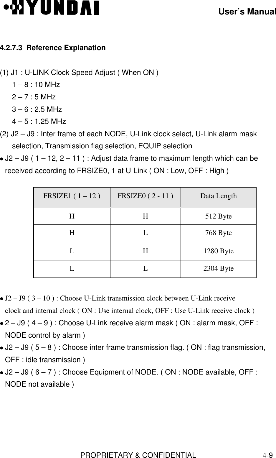
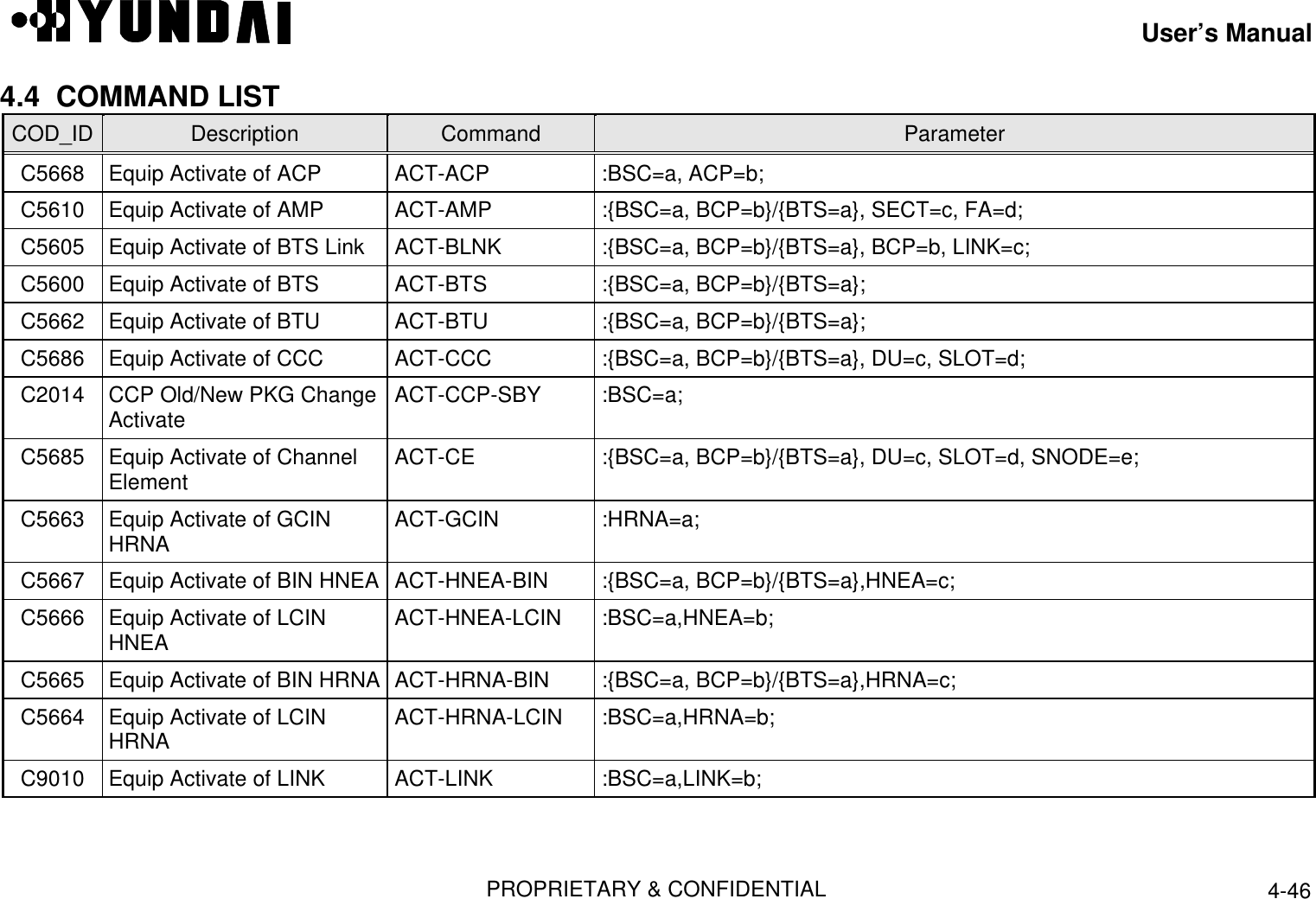
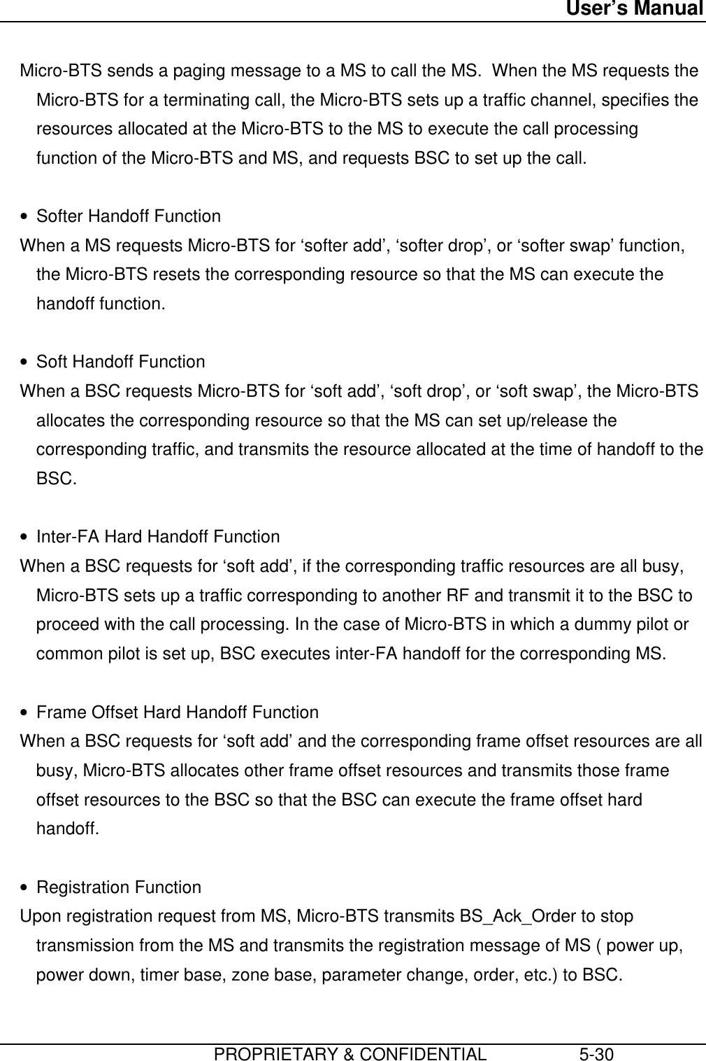
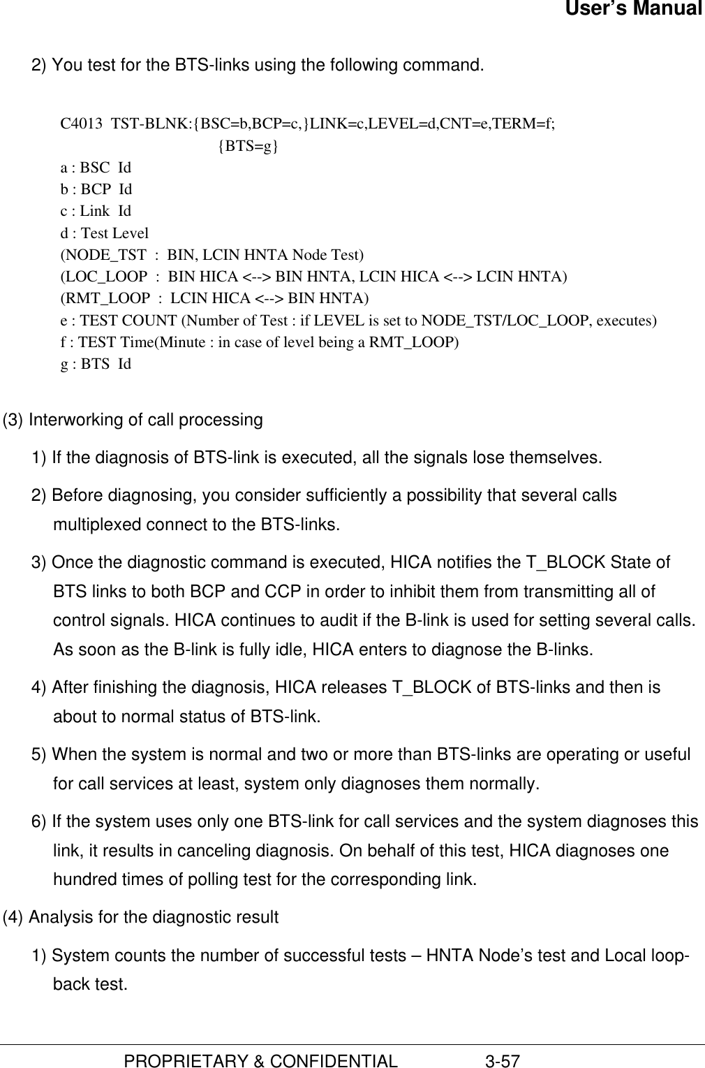
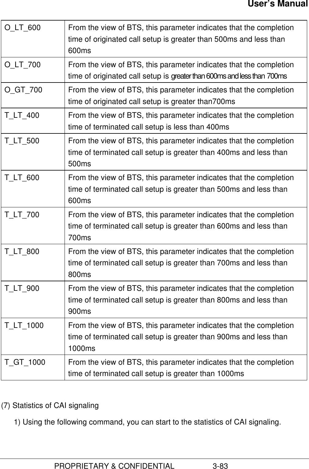
![User’s ManualPROPRIETARY & CONFIDENTIAL 4-47COD_ID Description Command ParameterC9009 Equip Activate of Link Set ACT-LSET :BSC=a;C3003 Overload Threshold Activate ACT-OVLD-THR :{PRC=a, BSC=b}/{PRC=a,BSC=b,BCP=c}/{BTS=a}, ONOFF=d;C5637 Equip Activate of SIP ACT-SIP :BSC=a, SIP=b;C5639 Equip Activate of SVE ACT-SVE :BSC=a, SIP=b, SVP=c, SVE=d;C5638 SVP of Equip Activate ACT-SVP :BSC=a, SIP=b, SVP=c;C2007 Add Loading Block ADD-LDNG-BLK :{BSC=a}/{BSC=a, BLKTYPE=b}, HDTYPE=c, BLKNAME=d,VERSION=e;C5242 Add BTS NEBR ADD-NEBR :{BSC=a, BCP=b}/{BTS=a}, SECT=c, FA=d, NBRBTS=e, NBRSECT=f;C4501 Add Mobile MARKOVfunction ADD-REG-MARK :MIN=a,SCM=b,BTS=c,RATE=d;C1000 Allow alarm message output ALW-ALM-MSG :AN=a;C1020 Allow reflection of alarmstatus ALW-ALM-STSC1001 Allow audio alarm output ALW-AUD-ALM [ :GRD=a];C6404 Allow daily statistics ALW-DRPT-MSG :BSC=a;C1002 Allow fault message output ALW-FLT-MSG :FN=a;C6403 Allow hourly statistics ALW-HRPT-MSG :BSC=a;C6405 Allow monthly statistics ALW-MRPT-MSG :BSC=a;C4401 Allow periodic diagnostic ALW-PED-TST :DEV=a,{BSC=b, BCP=c}/{BTS=b}/{BSC=b, SIP=c};COD_ID Description Command Parameter](https://usermanual.wiki/Hyundai-Electronics-Co/HD-MIC1900/User-Guide-48794-Page-271.png)
![User’s ManualPROPRIETARY & CONFIDENTIAL 4-48C3503 Allow status message output ALW-STS-MSG :CODE=a;C4301 Allow device test ALW-TST :DEV=a, MODE=b {,BSC=c};C9018 Correct of alarm status AUDIT-ALARMC5410 Block AMP BLK-AMP :{BSC=a, BCP=b}/{BTS=a}, SECT=c, FA=d;C5405 Block BTS Link BLK-BLNK :{BSC=a, BCP=b}/{BTS=a}, LINK=c;C5400 Block BTS BLK-BTS :{BSC=a, BCP=b}/{BTS=a};C5486 Block CCC BLK-CCC :{BSC=a, BCP=b}/{BTS=a}, DU=c, SLOT=d;C5485 Block Channel Element BLK-CE :{BSC=a, BCP=b}/{BTS=a}, DU=c, SLOT=d, SNODE=e;C5437 Block SIP BLK-SIP :BSC=a, SIP=b;C5439 Block SVE BLK-SVE :BSC=a, SIP=b, SVP=c, SVE=d;C5438 Block SVP BLK-SVP :BSC=a, SIP=b, SVP=c;C5116 Change Access ChannelParameter value CHG-AC-PARA :{BSC=a, BCP=b}/{BTS=a}, FA=c, SECT=d [,Param];C5119 Change Access Channelmessage CHG-ACC-MSG :{BSC=a, BCP=b}/{BTS=a}, FA=c, SECT=d [,Param];C1023 Change BCP Alarm CHG-ALM-BCP :{BSC=a[,BCP=b]},REG=c,BIT=d,ALM_CODE=e,DEV=f,SECT=g,CDMA=h,EQUIP=i;C3113 Change BCP Device Control CHG-BCP-CTRL :CTRL=a{,BSC=b,BCP=c}/{,BTS=b},BLNKCTRL=d,CEDYNCTRL=e,CDMACHDYNCTRL=f,FAILTIME=g;](https://usermanual.wiki/Hyundai-Electronics-Co/HD-MIC1900/User-Guide-48794-Page-272.png)
![User’s ManualPROPRIETARY & CONFIDENTIAL 4-49COD_ID Description Command ParameterC4704 Change HICA BER CHG-BER-HICA :LINKTYPE=a,BERTHR=b,SYNCTHR=c,SLIPTHR=d,CRCBPLRTHR=e;C4703 Change BER Diagnostic CHG-BER-TST :{BSC=a,BCP=b}/{BTS=a},AUTOFLAG=c,TERM=d,THRESHOLD=e;C5105 Change BLINKConfiguration CHG-BLNK-CONF :{BSC=a, BCP=b}/{BTS=a}, LINK=c[,USRPOFF];C3509 Change BLINK ErrorParameter CHG-BLNK-ERR :TYPE=a, {BSC=b,BCP=c}/{BTS=b}, WINSIZE=d, FREERATE=e;C5134 Change BSC ConfigurationInformation CHG-BSC-CONF :BSC=a [, PARAM];C5100 Change BTS ConfigurationInformation CHG-BTS-CONF :{BSC=a, BCP=b}/{BTS=a} [,Param];C5112 Change CDMA ChannelConfiguration CHG-CDMA-CONF :{BSC=a, BCP=b}/{BTS=a}, FA=c [,Param];C5102 Change CDMA Information CHG-CDMA-INFO :FA=a, CHNUM=b;C5114 Change Channel ElementType CHG-CE-TYPE :{BSC=a, BCP=b}/{BTS=a}, DU=c, SLOT=d, SNODE=e, TYPE=f [,Param];C5132 Change Forward Link PowerControl Data Set1 CHG-FPC1-INFO :{BSC=a, BCP=b}/{BTS=a}, FA=c, SECT=d [,Param];C5144 Change Forward Link PowerControl Data Set2 CHG-FPC2-INFO :{BSC=a, BCP=b}/{BTS=a}, FA=c, SECT=d [,Param];COD_ID Description Command Parameter](https://usermanual.wiki/Hyundai-Electronics-Co/HD-MIC1900/User-Guide-48794-Page-273.png)
![User’s ManualPROPRIETARY & CONFIDENTIAL 4-50C5113 Change Forward Link PowerData Value CHG-FWDP-INFO :{BSC=a, BCP=b}/{BTS=a}, FA=c, SECT=d [,Param];C5142 Change NEBR Priority CHG-NEBR-PRI :{BSC=a, BCP=b}/{BTS=a}, SECT=c, FA=d, INDEX=e [,Param];C9015 Change OPC Information CHG-OPC :BSC=a [, OPC=b][, MAXLNK=c];C3304 Change Overload ThresholdValue CHG-OVLD-THR :{BSC=a, BCP=b}/{BTS=a}, DEV=c, CRI=d, MAJ=e, MIN=f, ONSET=g;C5118 Change Paging ChannelParameter CHG-PC-PARA :{BSC=a, BCP=b}/{BTS=a}, FA=c, SECT=d [, PC=e], PCGAIN=f;C4403 Change Period TEST CHG-PED-TST :DEV=a, {BSC=b, BCP=c}/{BTS=b},DEVID=d,STIM=e,ETIM=f,CNT=g;C5117 Change Pilot/Sync ChannelParameter CHG-PSC-PARA :{BSC=a, BCP=b}/{BTS=a}, FA=c, SECT=d [,Param];C4503 Change Mobile MARKOVRegister CHG-REG-MARK :MIN=a,SCM=b,BTS=c,RATE=d;C5120 Change RF Control CardInformation CHG-RFC-PARA :{BSC=a, BCP=b}/{BTS=a}, FA=c, SECT=d [,Param];C5133 Change Reverse Link PowerControl Data Value CHG-RPC-INFO :{BSC=a, BCP=b}/{BTS=a}, FA=c, SECT=d [,Param];C5104 Change Sub Cell Data Value CHG-SCEL-INFO :{BSC=a, BCP=b}/{BTS=a}, FA=c, SECT=d [,Param];C5101 Change Sector InformationData Value CHG-SECT-INFO :{BSC=a, BCP=b}/{BTS=a}, SECT=c [,Param];C5106 Change System DATA CHG-SYS-PARA :{BSC=a, BCP=b}/{BTS=a}, FA=c, SECT=d [,Param];COD_ID Description Command Parameter](https://usermanual.wiki/Hyundai-Electronics-Co/HD-MIC1900/User-Guide-48794-Page-274.png)
![User’s ManualPROPRIETARY & CONFIDENTIAL 4-51C5115 Change Traffic ChannelParameter CHG-TC-PARA :{BSC=a, BCP=b}/{BTS=a}, FA=c [,Param];C4303 Change Automatic TestInformation CHG-TST :DEV=a, BSC=b, TERM=c, CNT=d;C1018 Check BSC Alarm CHK-BSC-ALM :BSC=a;C1017 Check BTS Alarm CHK-BTS-ALM :{BSC=a, BCP=b}/{BTS=a};C1003 Clear Audio Alarm CLR-AUD-ALMC5731 Deactivate ACP DACT-ACP :BSC=a, ACP=b;C5710 Deactivate AMP DACT-AMP :{BSC=a, BCP=b}/{BTS=a},SECT=c,FA=d;C5705 Deactivate BTS Link DACT-BLNK :{BSC=a, BCP=b}/{BTS=a}, LINK=c;C5700 Deactivate BTS DACT-BTS :{BSC=a, BCP=b}/{BTS=a};C5762 Deactivate BTU DACT-BTU :{BSC=a, BCP=b}/{BTS=a};C5786 Deactivate CCC DACT-CCC :{BSC=a, BCP=b}/{BTS=a}, DU=c, SLOT=d;C5785 Deactivate Channel Element DACT-CE :{BSC=a, BCP=b}/{BTS=a}, DU=c, SLOT=d, SNODE=e;C5763 Deactivate GCIN HRNA DACT-GCIN :HRNA=a;C5767 Deactivate BIN HNEA DAC-HNEA-BIN :{BSC=a, BCP=b}/{BTS=a},HNEA=c;C5766 Deactivate LCIN HNEA DACT-HNEA-LCIN :BSC=a,HNEA=b;C5765 Deactivate BIN HRNA DACT-HRNA-BIN :{BSC=a, BCP=b}/{BTS=a},HRNA=c;COD_ID Description Command ParameterC5764 Deactivate LCIN HRNA DACT-HRNA-LCIN :BSC=a, HRNA=b;](https://usermanual.wiki/Hyundai-Electronics-Co/HD-MIC1900/User-Guide-48794-Page-275.png)
![User’s ManualPROPRIETARY & CONFIDENTIAL 4-52C9012 Deactivate Link DACT-LINK :BSC=a, LINK=b;C5735 Deactivate Link Set DACT-LSET :BSC=a;C5737 Deactivate SIP DACT-SIP :BSC=a, SIP=b;C5739 Deactivate SVE DACT-SVE :BSC=a, SIP=b, SVP=c, SVE=d;C5738 Deactivate SVP DACT-SVP :BSC=a, SIP=b, SVP=c;C9003 Define DPC DEF-DPC :BSC=a, DPC=b;C9005 Define Link DEF-LINK :BSC=a, LINK=b, ACTIND=c, TSTSLC=d;C9004 Define Link Set DEF-LSET :BSC=a, LSHAR=b, ACTIND=c;C9016 Define SCCP DEF-SCCP :BSC=a, SYSID=b, SSN=c;C9006 Delete DPC DEL-DPC :BSC=a;C2008 Delete Loading Block DEL-LDNG-BLK :BSC=a [, BLKTYPE=b], BLKNAME=c;C9008 Delete Link DEL-LINK :BSC=a, LINK=b;C9007 Delete Link Set DEL-LSET :BSC=a;C4502 Delete Mobile MARKOVRegister DEL-REG-MARK :MIN=a;C9017 Delete SCCP DEL-SCCP :BSC=a;COD_ID Description Command ParameterC5016 Confirm Access ChannelParameter DIS-AC-PARA :{BSC=a, BCP=b}/{BTS=a}, FA=c, SECT=d, PC=e;](https://usermanual.wiki/Hyundai-Electronics-Co/HD-MIC1900/User-Guide-48794-Page-276.png)
![User’s ManualPROPRIETARY & CONFIDENTIAL 4-53C5019 Output ACC Message DIS-ACC-MSG :{BSC=a, BCP=b}/{BTS=a}, FA=c, SECT=d;C5068 Output ACP ConfigurationInformation DIS-ACP-CONF :BSC=a;C4508 Output Active MARKOV Call DIS-ACT-MARKC1014 Output ACP Alarm DIS-ALM-ACP [ :BSC=a [, ACP=b [, SRC=c]]];C1022 Output BCP Alarm DIS-ALM-BCP :{BSC=a [, BCP=b]}/{BTS=c};C1006 Output Alarm Information DIS-ALM-INFO N :AN=a;C1004 Output Current Alarm Status DIS-ALM-STS {[ :BSC=a [, BCP=b]]}/{[BTS=a]}[,DETAIL=c];C5010 Output AMP ConfigurationInformation DIS-AMP-CONF {BSC=a, BCP=b}/{BTS=a}, SECT=c;C1005 Output Audio Alarm DIS-AUD-ALMC4512 Output BCP Call Number DIS-BCP-CALL :{BSC=a, BCP=b}/{BTS=a},FA=c;C3109 Output BCP Device CTRL DIS-BCP-CTRL :{BSC=a, BCP=b}/{BTS=a};C4702 Output BER Information DIS-BER-INFO :PROC=a,BSC=b;C3208 Output BIN HNEA Status DIS-BIN-HLEA :{BSC=a, BCP=b}/{BTS=a};C3206 Output BIN Node Status DIS-BIN-NODE :{BSC=a, BCP=b}/{BTS=a};C3203 Output BIN Processor Status DIS-BIN-PRC :{BSC=a, BCP=b}/{BTS=a};COD_ID Description Command ParameterC2004 Output Block Loading HistoryFunction DIS-BLLD-HIS :{BSC=a, PROC=b [,{ACP=c}/{SIP =c, SVP=d}/{BCP=c}]}/{BTS=a,PROC=b [, DU=c [,CCC=d]]}, BLKNAME=e;C5005 Output BLINK Configuration DIS-BLNK-CONF :{BSC=a, BCP=b}/{BTS=a};](https://usermanual.wiki/Hyundai-Electronics-Co/HD-MIC1900/User-Guide-48794-Page-277.png)
![User’s ManualPROPRIETARY & CONFIDENTIAL 4-54C3508 Output BLINK Error Parameter DIS-BLNK-ERR :{BSC=a, BCP=b}/{BTS=a};C3004 Output BLINK Status DIS-BLNK-STS :{BSC=a, BCP=b}/{BTS=a};C3401 Output BSC ACP Information DIS-BSC-ACP :BSC=a;C5034 Output BSC ConfigurationInformation DIS-BSC-CONFC5081 BSC Information Output DIS-BSC-INFOC3102 BTS Card Status Output DIS-BTS-CARD :{BSC=a, BCP=b}/{BTS=a}, CARD=c;C5000 Confirm BTS ConfigurationInformation DIS-BTS-CONF :{BSC=a, BCP=b}/{BTS=a};C5082 Confirm & Output BTSOperation Information DIS-BTS-INFO :{BSC=a, BCP=b}/{BTS=a};C3101 Output BCP Processor Status DIS-BTS-PRC :{BSC=a [, BCP=b]}/{BTS=a};C3402 Output BTS SACA Status DIS-BTS-SACA :{BSC=a [, BCP=b]}/{BTS=a};C5062 Output BTU Configuration DIS-BTU-CONF :{BSC=a, BCP=b}/{BTS=a};C3307 Output Call Number DIS-CALL-STS :PROC=a, {BSC=b, BCP=c}/{BTS=b};COD_ID Description Command ParameterC3103 Output CC Status DIS-CC-STS :{BSC=a, BCP=b}/{BTS=a};C3001 Output CCP Status DIS-CCP-STS [ :BSC=a];C2017 Output CCP Version DIS-CCP-VER :BSC=bsc, SIDE=b;](https://usermanual.wiki/Hyundai-Electronics-Co/HD-MIC1900/User-Guide-48794-Page-278.png)
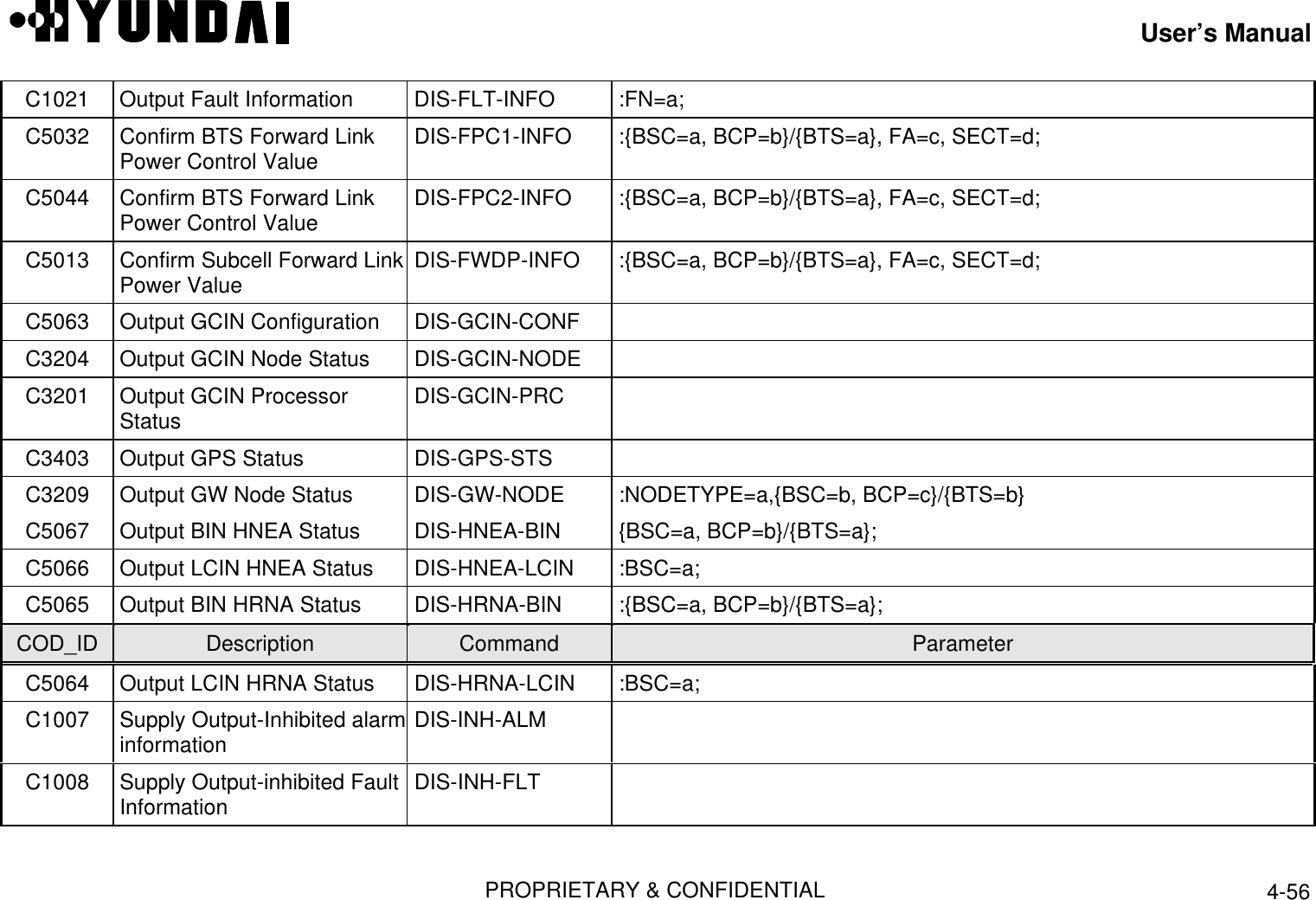
![User’s ManualPROPRIETARY & CONFIDENTIAL 4-55C5012 Confirm CDMA ConfigurationInformation DIS-CDMA-CONF :{BSC=a, BCP=b}/{BTS=a};C5002 Confirm CDMA ChannelInformation DIS-CDMA-INFOC3108 Output CDMA ChannelInformation DIS-CDMACH-LIST :{BSC=a, BCP=b}/{BTS=a};C3106 Output CE Status DIS-CE-STS :{BSC=a, BCP=b}/{BTS=a},DU=c;C5090 Output CDMA Channel ListMessage DIS-CHLIST-MSG :{BSC=a, BCP=b}/{BTS=a},SECT=c;C0001 Output Command History DIS-CMD-HIS :DATE=a, STIME=b, ETIME=c, TYPE=d, CODE=e;C9000 Output CSB ConfigurationInformation DIS-CSB-INFO [ :BSC=a];C9019 Output CSB Status DIS-CSB-STS [ :BSC=a];C4509 Output Deactivated MARKOVCall DIS-DACT-MARKC6017 Output statistic data CollectionStatus DIS-DATA-COLLCOD_ID Description Command ParameterC5014 Output DU ConfigurationInformation DIS-DU-CONF :{BSC=a, BCP=b}/{BTS=a}, SHELF=c [, SLOT=d];C5089 Output Extended SystemParameter DIS-EXTSYS-MSG :{BSC=a, BCP=b}/{BTS=a}, SECT=c, FA=d;](https://usermanual.wiki/Hyundai-Electronics-Co/HD-MIC1900/User-Guide-48794-Page-279.png)
![User’s ManualPROPRIETARY & CONFIDENTIAL 4-57C6003 Output Output-inhibited FaultStatistics List DIS-INH-MSGC3502 Output Output-inhibitedStatus Messages List DIS-INH-STSC3207 Output LCIN HNEA NodeInformation DIS-LCIN-HNEA :BSC=a;C3205 Output LCIN Node Status DIS-LCIN-NODE :BSC=a;C3202 Output LCIN ProcessorStatus DIS-LCIN-PRC :BSC=a;C2003 Loading Table OutputFunction DIS-LDNG-TBL :BSC=a, PROC=b;C9001 Output Link Information DIS-LINK-INFO :BSC=a, LINK=b;C5036 Confirm MSC Link ChannelConfiguration Information DIS-MCH-CONF :BSC=a, LINK=b;C5035 Output MSC LinkConfiguration Information DIS-MLNK-CONF :BSC=a;COD_ID Description Command ParameterC3005 MSC Link Status Output DIS-MLNK-STS :BSC=a, LINK=b;C0002 Output Message History DIS-MSG-HIS :DATE=a, STIME=b, ETIME=c, TYPE=d, CODE=e;C5042 Confirm BTS Neighbor List DIS-NEBR-INFO :{BSC=a, BCP=b}/{BTS=a}, SECT=c, FA=d;C3306 Output Out Of Service Status DIS-OOS-STS :DEV=a, TYPE=b;C3301 Output CPU Overload Status DIS-OVLD-STS :PRC=a, {BSC=b [,BCP=c]}/{BTS=b};](https://usermanual.wiki/Hyundai-Electronics-Co/HD-MIC1900/User-Guide-48794-Page-281.png)
![User’s ManualPROPRIETARY & CONFIDENTIAL 4-58C3302 Output CPU Overload Limit DIS-OVLD-THR :PRC=a, {BSC=b [,BCP=c]}/{BTS=b};C5018 Confirm Paging ChannelParameter DIS-PC-PARA :{BSC=a, BCP=b}/{BTS=a}, FA=c, SECT=d, PC=e;C4003 Output periodic TestInformation DIS-PED-INFO :DEV=a, BSC=b;C5883 Output PLD Information DIS-PLD-INFO [ :BSC=a];C5031 Output PN Cell Information DIS-PN-CELL [ :PILOT=a];C2005 Processor Loading HistoryFunction DIS-PRLD-HIS :{BSC=a, PROC=b [, {ACP=c}/{SIP=c[,SVP=d]}/{BCP=c}]}/{BTS=a,PROC=b [,DU=c [,CCC=d]]};C5017 Confirm Pilot/Sync ChannelParameter DIS-PSC-PARA :{BSC=a, BCP=b}/{BTS=a}, FA=c, SECT=d;C4507 Confirm Mobile MARKOVRegister DIS-REG-MARKC5020 Output RFC ParameterFunction DIS-RFC-PARA :{BSC=a, BCP=b}/{BTS=a}, FA=c, SECT=d;COD_ID Description Command ParameterC5033 Confirm BTS Reverse LinkPower Control Value DIS-RPC-INFO :{BSC=a, BCP=b}/{BTS=a}, FA=c, SECT=d;C4002 Output Reverse Link TestInformation DIS-RSV-INFO :DEV=a, BSC=b;C9002 Output SCCP Information DIS-SCCP-INFO [ :BSC=a];C5004 Confirm Subcell Data Value DIS-SCEL-INFO :{BSC=a, BCP=b}/{BTS=a}, SECT=c, FA=d;](https://usermanual.wiki/Hyundai-Electronics-Co/HD-MIC1900/User-Guide-48794-Page-282.png)
![User’s ManualPROPRIETARY & CONFIDENTIAL 4-59C5001 Confirm Sector Information DIS-SECT-INFO :{BSC=a, BCP=b}/{BTS=a}, SECT=c;C5004 Confirm Subcell Data Value DIS-SCEL-INFO :{BSC=a, BCP=b}/{BTS=a}, CFID=c, SECT=d;C5003 Confirm Subcell Key DIS-SCEL-KEY {BSC=a, BCP=b}/{BTS=a},SECT=c,CFID=d;C5001 Confirm Sector Information DIS-SECT-INFO :{BSC=a, BCP=b}/{BTS=a}, SECT=c;C5037 Confirm & Output SIPConfiguration DIS-SIP-CONF :BSC=a;C3002 Output SIP Status DIS-SIP-STS :BSC=a [,SIP=b];C6000 Output List about statisticitem DIS-STAT-ITEMC6001 Output Activated StatisticItem DIS-STAT-JOB [ :BSC=a];C3501 Confirm Status Information DIS-STS-INFO [ :CODE=a];C5039 Confirm & Output of SVEConfiguration in SVP DIS-SVE-CONF :BSC=a, SIP=b, SVP=c;COD_ID Description Command ParameterC3004 Output Vocoder Status DIS-SVE-STS :BSC=a, SIP=b [, SVP=c];C5038 Confirm & Output SVPConfiguration in SIP DIS-SVP-CONF :BSC=a, SIP=b;C3003 Output SVP Status DIS-SVP-STS :BSC=a [, SIP=b];C5087 Output Sync-ChannelMessage DIS-SYNC-MSG :{BSC=a, BCP=b}/{BTS=a}[, SECT=c][, FA=d];](https://usermanual.wiki/Hyundai-Electronics-Co/HD-MIC1900/User-Guide-48794-Page-283.png)
![User’s ManualPROPRIETARY & CONFIDENTIAL 4-60C5006 Confirm BTS SystemParameter DIS-SYS-PARA :{BSC=a, BCP=b}/{BTS=a}[, SECT=c][, FA=d];C5884 Confirm System Version DIS-SYS-VER :BSC=a;C5088 Output System parameterMessage DIS-SYSPARA-MSG :{BSC=a, BCP=b}/{BTS=a}[, SECT=c][, FA=d];C5015 Confirm Traffic ChannelParameter DIS-TC-PARA :{BSC=a, BCP=b}/{BTS=a}, FA=c;C3105 Output TCE Status DIS-TCE-STS :{BSC=a, BCP=b}/{BTS=a}, DU=c;C3404 Confirm TSGA Status DIS-TSGA-STS :BSC=a;C4001 Confirm Test Information DIS-TST-INFO :BSC=c;C2016 Run CCP New PKG DRV-CCP-SBY :BSC=a;C1009 Inhibit Alarm Message output INH-ALM-MSG :AN=a;C1019 Inhibit Alarm Status output INH-ALM-STSC1010 Inhibit Audible Alarm INH-AUD-ALM [ :GRD=a];COD_ID Description Command ParameterC6304 Inhibit daily Statistics output INH-DRPT-MSG :BSC=a;C1011 Inhibit Fault Message output INH-FLT-MSG :FN=a;C6303 Inhibit hourly statistics output INH-HRPT-MSG :BSC=a;C9013 Inhibit use of LINK INH-LINK :BSC=a, LINK=b;C6305 Inhibit monthly statisticsoutput INH-MRPT-MSG :BSC=a;](https://usermanual.wiki/Hyundai-Electronics-Co/HD-MIC1900/User-Guide-48794-Page-284.png)
![User’s ManualPROPRIETARY & CONFIDENTIAL 4-61C4402 Inhibit periodic diagnostic INH-PED-TST :DEV=a,{BSC=b, BCP=c}/{BTS=b}/{BSC=a, SIP=b};C3504 Inhibit Status MessageOutput INH-STS-MSG :CODE=a;C4302 Inhibit automatic test INH-TST :DEV=a,MODE=b,BSC=c;C2015 Return CCP Old Package REV-CCP-SBY :BSC=a;C5342 Remove NEBR RMV-NEBR :{BSC=a, BCP=b}/{BTS=a},SECT=c,FA=d,NBRPN=e;C2002 Loading Partial Block RPL-LDNG-BLK :{BSC=a [, BCP=b]/[, SIP=b]}/{BTS=c}, BLKTYPE=d, BLKNAME=e,VERSION=f;C2009 Restart BTS CARD RST-BTS-CARD :{BSC=a, BCP=b}/{BTS=a} [, Param];C2011 Restart CCP RST-CCP-PRC :CCP=a;C2013 Start CCP Standby Loading RST-CCP-SBY :BSC=a, VERSION=b;C2001 Restart function of Processor RST-LDNG-PRC :{BSC=a,PROC=b[,{ACP=c}/{SIP=c ,SVP=d[,SVE=e]]/{BCP=f}]}}/{BTS=a, PROC=b} , SIDE=c, LEVEL=d;COD_ID Description Command ParameterC6217 Stop Collection of Statistics STOP-DATA-COLL :BSC=a;C6201 Stop statistic job on going STOP-STAT-JOB :BSC=a, JOB=b, MPRD=c ;C4505 Stop TEST CALL STOP-TEST-CALL MIN=a;C4202 Stop Diagnostic STOP-TST :DEV=a, {BSC=b, BCP=c}/{BTS=b},SIP=d;C6117 Start Statistic Collection STRT-DATA-COLL :BSC=a;C6110 Start Alarm Statistics STRT-STAT-ALM :BSC=a [, BCP=b], ITEM=c, MPRD=d, MTIM=e;](https://usermanual.wiki/Hyundai-Electronics-Co/HD-MIC1900/User-Guide-48794-Page-285.png)
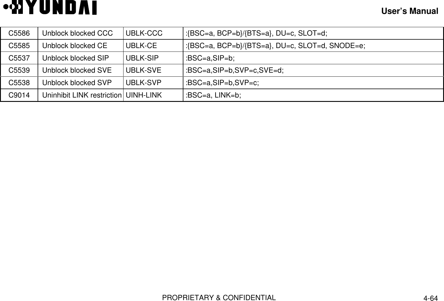
![User’s ManualPROPRIETARY & CONFIDENTIAL 4-62C6118 Start CAI Statistics STRT-STAT-CAI :BSC=a [, BCP=b], MPRD=c, MTIM=d;C6104 Start Channel ElementStatistic Item STRT-STAT-CE :BSC=a [, BCP=b], MPRD=c, MTIM=d;C6109 Start Fault Statistics STRT-STAT-FLM :BSC=a [, BCP=b], ITEM=c, MPRD=d, MTIM=e;C6103 Start Handoff Statistics item STRT-STAT-HDOF :BSC=a [, BCP=b], ITEM=c, MPRD=d, MTIM=e;C6106 Start Link statistics item STRT-STAT-LINK :BSC=a [, BCP=b], MPRD=c, MTIM=d ;C6113 Start LR Statistics item STRT-STAT-LR :BSC=a, MPRD=b, MTIM=c;C6121 Start No.7 MTP Statisticsitem STRT-STAT-MTP :BSC=a, ITEM=b, MPRD=c, MTIM=e;C6112 Start Paging statistics item STRT-STAT-PAG :BSC=a [, BCP=b], MPRD=c, MTIM=d ;C6111 Start BTS performancestatistics item STRT-STAT-PERF :BSC=a, BCP=b, MPRD=c, MTIM=d;COD_ID Description Command ParameterC6108 Start Processor statisticsitem STRT-STAT-PRC :BSC=a [, BCP=b][, SIP=c], ITEM=d, MPRD=e,MTIM=f;C6107 Start RF Statistics item STRT-STAT-RF :BSC=a [, BCP=b], MPRD=c, MTIM=d;C6120 Start RF Fault Statisticsitem STRT-STAT -RFF :BSC=a [, BCP=b], MPRD=c, MTIM=d;C6122 Start NO.7 SCCP Statisticsitem STRT-STAT-SCCP :BSC=a [, BCP=b], MPRD=c, MTIM=d;C6102 Start Traffic Statistics item STRT-STAT-TRAF :BSC=a [, BCP=b], ITEM = c, MPRD=d, MTIM=e;](https://usermanual.wiki/Hyundai-Electronics-Co/HD-MIC1900/User-Guide-48794-Page-286.png)
![User’s ManualPROPRIETARY & CONFIDENTIAL 4-63C6105 Start Vocoder Statisticsitem STRT-STAT-VOC :BSC=b [, SIP=c], MPRD=e, MTIM=f;C4504 Allow Reserved Test STRT-TEST-CALL :MIN=a, CALLTYPE=b, DATATYPE=c;C4201 Start Reverse Device Test STRT-TST :DEV=a, {BSC=b, BCP=c}/{BTS=b}, DEVID=c, STIM=d, LEVEL=e, TERM=f,COUNT=g;C3210 Switch HICA Processor SWI-HICA-PRC :PROC=a {, BSC=b, BCP=c}/{BTS=c};C2012 Switch BTS RFC SWT-PRC :BSC=a,PROC=b,BCP=c,BTS=d,DU=e;C3410 Switch TFSA SWT-TFSA :SWITYPE=a,TFSAID=b,ONOFF=c;C4511 Start BCP CALL TEST-BCP-CALL :{BSC=a, BCP=b}/{BTS=a},FLAG=c,SECT=d,FA=e,CALLNUM=f,GAIN=g;C4102 Test BTS Link TST-BLNK :{BSC=a, BCP=b}/{BTS=a}, LINK=c, LEVEL=d, CNT=e, TERM=f;C4701 Test BLNK BER TST-BLNK-BER :{BSC=a, BCP=b}/{BTS=a}, LINK=c,TERM=d;COD_ID Description Command ParameterC4104 Test each CE Device TST-CE :{BSC=a, BCP=b}/{BTS=a}, DUID=c, CDCA=d, SUNNODE=f, LEVEL=g,CNT=h;;C4105 Test HRNA TST-HRNA :DEV=a, {BSC=b, BCP=c}/{BTS=bts}, HRNA=d, NODE=e;C4103 Test each VocoderDevice TST-SVE :BSC=a, SIP=b, SVP=c, SVE=d, LEVEL=e;C5510 Unblock blocked AMP UBLK-AMP :{BSC=a, BCP=b}/{BTS=a}, SECT=c, FA=d;C5505 Unblock blocked BLINK UBLK-BLNK :{BSC=a, BCP=b}/{BTS=a}, LINK=c;C5500 Unblock blocked BTS UBLK-BTS :{BSC=a, BCP=b}/{BTS=a};](https://usermanual.wiki/Hyundai-Electronics-Co/HD-MIC1900/User-Guide-48794-Page-287.png)