Hyundai Electronics Co HD-MIC1900A PCS CDMA Base Station Transceiver Subsystem User Manual FCC cover
Hyundai Electronics Industries Co Ltd PCS CDMA Base Station Transceiver Subsystem FCC cover
Users Manual

USER’S MANUAL
for HD-BSC 960 and HD-MIC 1900
1999. 11
Copyright 1999 Hyundai Electronics Industries Co., Ltd.
All rights are reserved. No part of this document may be used or
reproduced in any means without the prior written permission of
the copyright holders.

User’s Manual
PROPRIETARY & CONFIDENTIAL
Table of Contents
Chapter 1. System Overview
1.1 Purpose of this document
1.2 Features of Hyundai CDMA System
1.3 Overview
Chapter 2. BSC Basics
2.1 System Overview and Specification
2.1.1 Overview
2.1.2 Specifications and Characteristics
2.2 H/W Structure and Function
2.2.1 Overview
2.2.2 Structure of Subsystem
2.3 S/W Structure and Function
2.3.1 Overview
2.3.2 Structure
Chapter 3. BSM Operation & Administration
3.1 BSM Operation
3.1.1 Overview
3.1.2 Main Display Structure
3.1.3 Main Button
3.1.4 Command Buttons
3.1.5 Service Button
3.1.6 Operations of “Alarm” window
3.2 System Status Management
3.2.1 System Status Test
3.2.2 System Diagnosis
3.2.3 Statistics
3.3 Data Management
3.3.1 Access Channel Parameter
3.3.2 Access Parameter

User’s Manual
PROPRIETARY & CONFIDENTIAL
3.3.3 Information of Micro-BTS Configuration
3.3.4 Base Station CDMA Environment
3.3.5 Base Station CDMA Information
3.3.6 Base Station Channel List Message
3.3.7 Extended System Parameter Information
3.3.8 Forward Link Power Information
3.3.9 Paging Channel Parameter
3.3.10 Psync Channel Parameter
3.3.11 RFC Parameter
3.3.12 Forward Link Power Control Data
3.3.13 Reverse Link Power Control Data
3.3.14 Base Station Cell Information
3.3.15 Corresponding Sector Information of Micro-BTS
3.3.16 Sync Channel Message
3.3.17 System Parameter
3.3.18 System Parameter Message
3.3.19 Traffic Channel Parameter
3.4 Call Processing System
3.4.1 Overview
3.4.2 Call Processing Flow
3.4.3 Call Trace
3.4.4 Call Release Reason and State
Chapter 4. BSC References
4.1 Rack Configuration
4.2 DIP Switch & Strap
4.2.1 Summary
4.2.2 Purpose
4.2.3 Address Setting in Common
4.2.4 MCDA (Main Control & Duplication board Assembly-A1)
4.2.5 CIFA-A1 (Cin Interface Function board Assembly-A1)
4.2.6 HICA-A2 (High capacity Ipc Control board Assembly-A2)
4.2.7 HRNA-A2 (High capacity Routing Node Assembly-A2)

User’s Manual
PROPRIETARY & CONFIDENTIAL
4.2.8 HNTA-A2 (High capacity ipc Node & T1 interface Assembly-A2)
4.2.9 TFSA-A1 (Time & Frequency Split Assembly-A1)
4.2.10 TSGA-A1 (Time & frequency Splitting Generation Assembly-A1)
4.2.11 TFDA-A1 (Time & Frequency Distribution Assembly-A1)
4.2.12 VSIA-C1 (Vocoder Selector Interface Assembly-C1)
4.2.13 VSOA-A1 (Vocoder Selector Operation Assembly-A1)
4.2.14 CHBB-A1 (Cin Hipc Back Board-A1)
4.2.15 CCBB-A1 (CCp Back wiring Board-A1)
4.2.16 ACPA-A1 (Alarm Control Processor Assembly-A1)
4.2.17 SDBB-A1 (CKd Split & Distributed Back Board-A1)
4.2.18 TSBB-A1 (TSb Back Board-A1)
4.2.19 BABB-A1 (Bsc Alarm Back Board-A1)
4.2.20 HSBB-A1 (HIPC Small BackBoard-A1)
4.3 LED Descriptions
4.4 Command List
4.5 Acronym
Chapter 5. Micro-BTS Basics
5.1 System Overview and Specification
5.1.1 Overview
5.1.2 Functions
5.1.3 System Specification
5.2 Micro-BTS Structure and Configuration
5.2.1 Micro-BTS Structure
5.2.2 Micro-BTS Block Configuration
5.3 H/W Structure and Function
5.3.1 BMP
5.3.2 DU
5.3.3 TFU
5.3.4 RFU
5.3.5 Antenna Subsystem (AIU-RRU, AIDU-AAU)
5.3.6 BTU
5.3.7 RPU

User’s Manual
PROPRIETARY & CONFIDENTIAL
5.4 S/W Structure and Function
5.4.1 Overview
5.4.2 Basic Functions
5.5 Abbreviations
Chapter 6. Micro-BTS References
6.1 Rack Configuration
6.1.1 MBTR I (1.9GHz)
6.1.2 MBTR I (800MHz)
6.2 DIP Switch and Strap
6.2.1 Summary
6.2.2 Purpose
6.2.3 Address Setting in Common
6.2.4 BMPA-B2
6.2.5 CDCA-B1
6.2.6 BICA-B1
6.2.7 HLTA-B1
6.3 LED Descriptions
6.3.1 BMP
6.3.2 DU
6.3.3 TFU
6.3.4 RPU
6.4 Alarm Source List
6.5 Abbreviations

User’s Manual
PROPRIETARY & CONFIDENTIAL 1-1
Chapter 1 System Overview
1.1 Purpose of this document
This chapter contains description of Hyundai Micro-BTS PCS System that is operating on
800MHz and 1.9GHz frequency band, repectively.
1.2 Features of Hyundai CDMA System
There are two sub-systems in Hyundai CDMA system ; Micro-BTS and BSC. BSC
interfaces with switching equipment and has roles of vocoding and call processing. Micro-
BTS is functionally located between MS (Mobile Station) and BSC. Hyundai Micro-BTS
has channel resource unit and radio frequency RF unit similar to the conventional 3-Sector
BTS. Contrary to conventional 3-Sector BTS, Hyundai Micro-BTS is small in size, easily
can be installed and maintained, and is very cheap in cost.
1.3 Overview
Hyundai Micro-BTS system can support 2FA/3Sector using 2 racks, but Micro-BTS system
is composed of 1FA/3sector system for the FCC authorization. Thus this manual will
describe all of the specifications based on 1FA/3sector system.
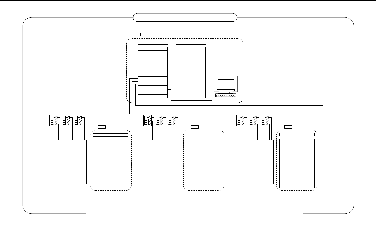
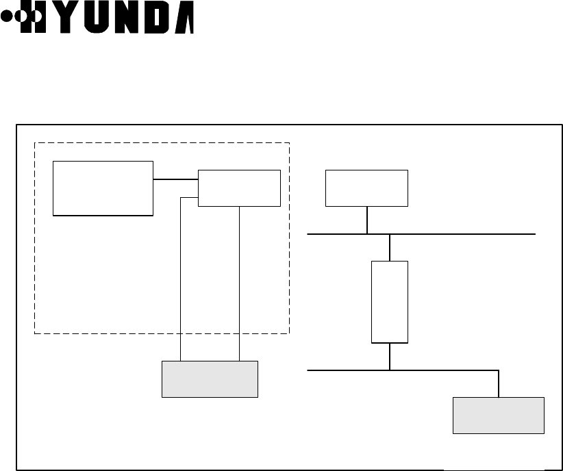
The system configuration is shown in Figure 1.1. In this configuration, there are 1 BSC and
3 Micro-BTS systems. Each Micro-BTS system is separately located in 3 sites. Micro-BTS
can use 2 types of antenna subsystem, RRU (Remote RF Unit) and AAU (Active Antenna
Unit). RRU is connected to Micro-BTS main system through AIU (Antenna Interface Unit)
and AAU through AIDU (Active Internal Distribution Unit). In case of trunk line, we have
several solutions, T1 and E1. We use T1 trunk line in USA. It means that we do not use
HLEA but HLTA as trunk card.
BSM manages and maintains Micro-BTS and BSC. It communicates with each system by
transmitting and receiving packets through LCIN. Its features include performance
management, configuration management, fault management, etc..
User’s Manual
PROPRIETARY & CONFIDENTIAL 1-2
RRU-B1
DEC, 8, 1998
System Configuration for Test_Bed
1x T1 leased line
1x T1 leased line 1x T1 leased line
GPS Antenna
MBTR1
RFU
AIU-B1
RPU
GPS Antenna
MBTR1
RFU
AIU-B1
RPU
GPS Antenna
MBTR1
RFU
RPU
AIU-B1
MBTR : Micro-BTS Rack
DU : Digital Unit
BMP : BTS Main Processor
TFU : Time & Frequency Unit
RFU : Radio Frequency Unit
RPU : Rectifier Power Unit
AIU : Antenna Interface Unit
RRU : Remote RF Unit
GPS : Global Positioning System
MSC : Mobile Switching Center
BSC : Base Station Controller
BSM : Base Station Manager
BSM
GPS Antenna
MSC(Switch)
MSC RACK
FANU
FANU
BSC-
GPS
CCP
TSB
LCIN
FANU
ACP
GCIN
BSC_COMR
DU BMP TFU
DU BMP TFU DU BMP TFU
ACP
CSB
RRU-B1 RRU-B1
Figure 1.1 Configuration of system for field trial
User’s Manual
PROPRIETARY & CONFIDENTIAL 2-1
Chapter 2 BSC Basics
2.1 System Overview and Specification
2.1.1 Overview
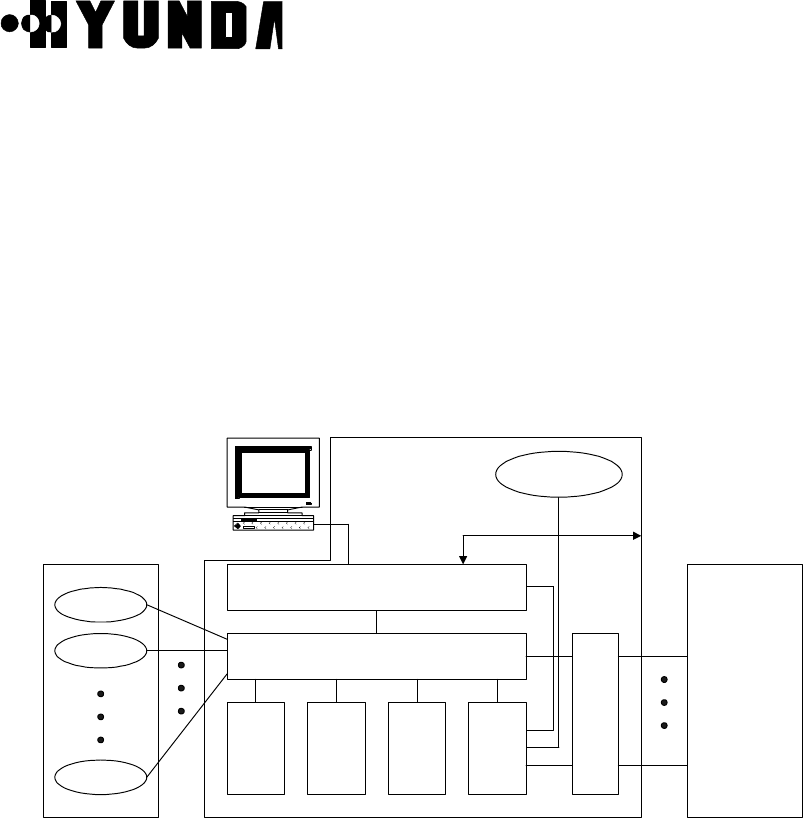
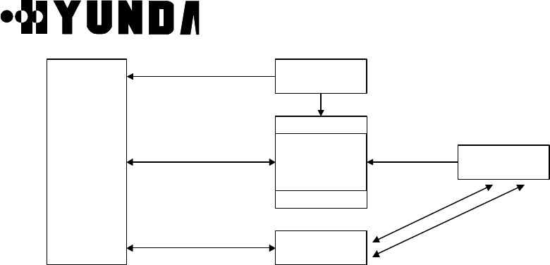
BSC is located between MSC and BTS. It carries out a wire/wireless link control function,
handoff function and transcoding function. And it is made up of a LCIN, GCIN, TSB, CCP,
CSB, CKD, BSC-GPS, and BSM block. [Refer to Fig.2.1].
BTS0
BTS1
BTS59
LCIN
CCP CSB
TSB
ACP CKD
BTS BSC MSC
BSM Others BSC
T1
T1
T1
T1
T1
IPC IPC IPC IPC
IPC
IPC
IPC
GCIN IPC
BSC-GPS
Figure 2.1 Configuration of BSC
Each block does following functions.
• BSM is a system used to operate the entire BSC and BTS, to manage their resources,
status and configuration, and to execute the user interface, and maintenance. It consists
of a SUN Sparc Workstation and the various types of input/output devices for enhancing
user's convenience.
• LCIN is a network that provides the communication paths of packet-type data between
subsystems. LCIN routes and transmits packet data within BSC and it has trunk interface
function between BSC and BTS.

User’s Manual
PROPRIETARY & CONFIDENTIAL 2-2
• GCIN is a network that provides the communication paths of packet-type data between
LCINs. GCIN also provides the communication path between BSM and other processor.
• CCP is a processor system that carries out the call processing and soft-handoff
processing function for entire BSC, allocates wireless resource of BSC, and controls
overload of vocoders and the main processor of BSC.
• CSB converts the IPC protocol of CCP into the No.7 protocol to access to MSC through
the trunk of TSB block.
• BSC-GPS is a system for providing the reference time used in the CDMA system. CKD
converts the clocks received from BSC-GPS and then, distributes synchronization
signals required for the system.
• ACP collects the various types of alarm status in BSC and then, reports them to BSM in
order to carry out system O & M efficiently.
• TSB is connected to MSC with T1 trunk. TSB converts the PCM voice signal of 64Kbps
received through this with the QCELP algorithm and it sends the converted signal to the
channel unit of BTS. In addition, it carries out the reverse function of the above.
Moreover, after being linked to the BTS, it executes a handoff function and power control
function on radio link.
2.1.2 Specifications and Characteristics
2.1.2.1 Specifications of BSC
(1) Capacities
• Number of controlled BTS : 60BTS/BSC
• Number of voice channel : 960 CH/BSC
• Number of BSC which are inter-accessible : 12BSC/MSC
• Maximum capable subscribers : 30,000 subscribers/BSC (Br 1%, 0.03Erlang)
(2) Link protocol

User’s Manual
PROPRIETARY & CONFIDENTIAL 2-3
• BSC-MSC Link
T1 for Traffic
SS No.7 for signaling & control (ITU-T STD)
• BTS-BSC Link
Un-channelized T1
(3) Power
• DC - 48 V
• Integration of storage battery is possible.
(4) Specification of LCIN
• Up to 112 T1 Trunk to BTS
• Function of Remote Loop-back
• Function of transmit/receive of Remote alarm
(5) Specification of CCP & CSB
• Use 32bit Main Processor
• Interface function with LCIN
• Interface to MSC
(6) Specification of TSB
• Interface to MSC with T1
• Accepts 48 Transcoding channel per TSB
• 12 Vocoder Channels/Channel Card
(7) Specification of GCIN
• 4 links to a LCIN
• Up to 12 LCIN connection capability
• RS-422 links for LCIN links, BSM and other processors
(8) Specification of BSM
• Main Frame : Use commercial workstation
• Main Processor : SPARC Processor processing rate more than 80MIPS
• Main Memory : more than 64Mbyte
• Hard Disk : more than 2Gbyte
• Tape Drive : more than 150Mbyte
• Parallel Port : Connect with High Speed Printer
• HDLC Card : support the rate more than 2.048Mbps and functions of X.25
connection

User’s Manual
PROPRIETARY & CONFIDENTIAL 2-4
• Audio I/O Port : supply alarm function
• Software : Motif/X11, Informix DBMS
2.1.2.2 Characteristics
(1) Distributed control structure and duplication of main part
(2) Using the link that is capable of high reliability and high speed data transmit
(3) Increasing the trunk efficiency by packet transmit
(4) Real-time processing of system by real-time OS
User’s Manual
PROPRIETARY & CONFIDENTIAL 2-5
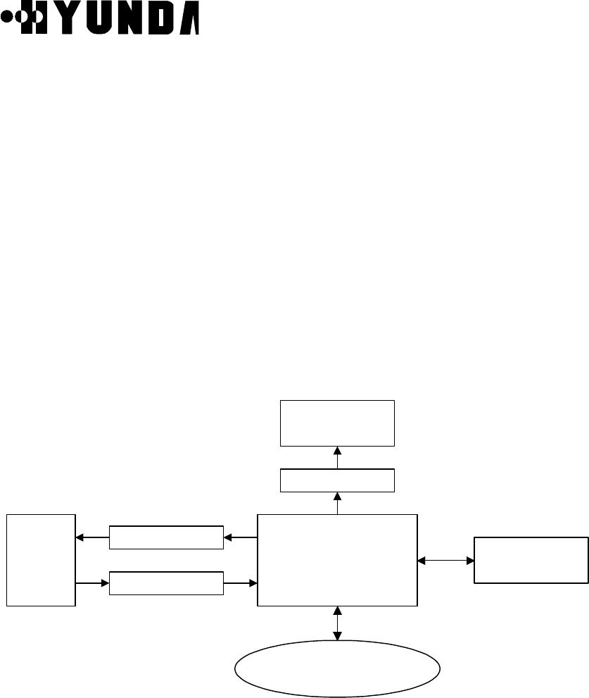
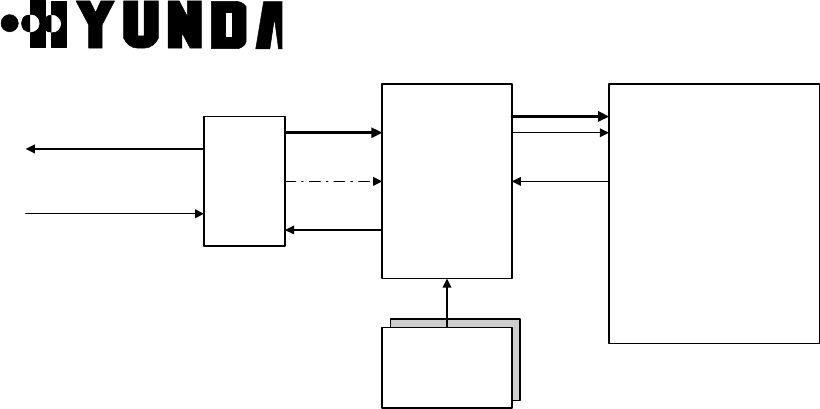
2.2 H/W Structure and Function
2.2.1 Overview
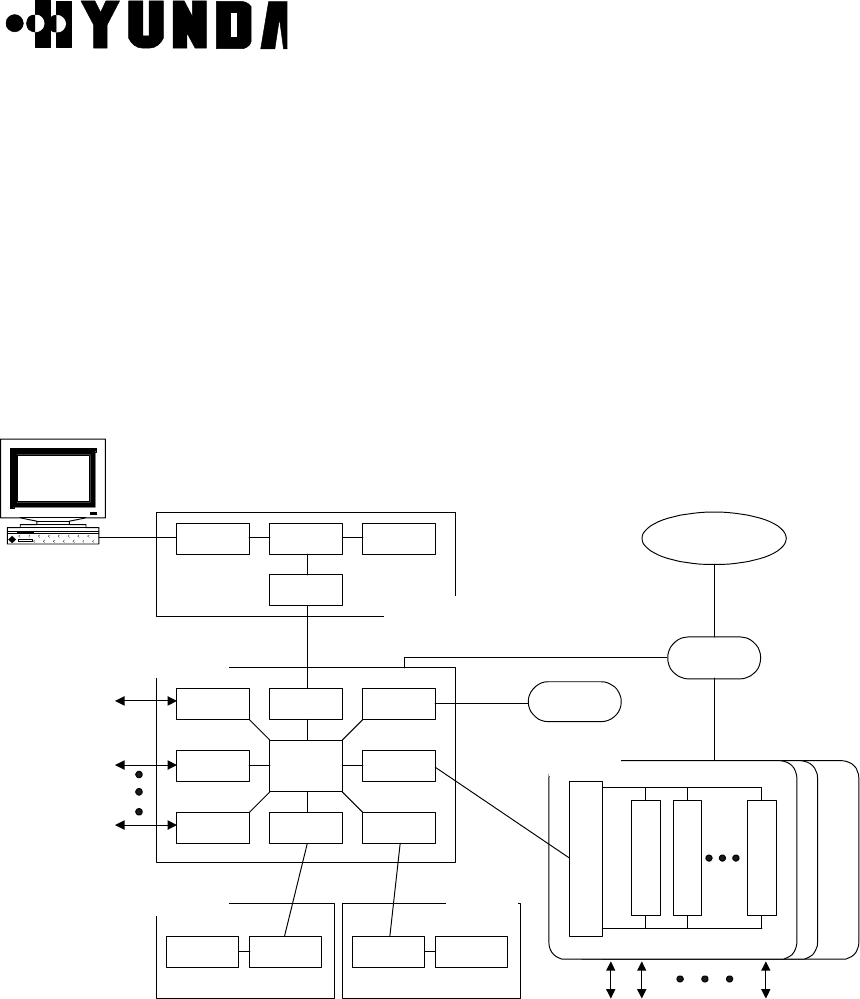
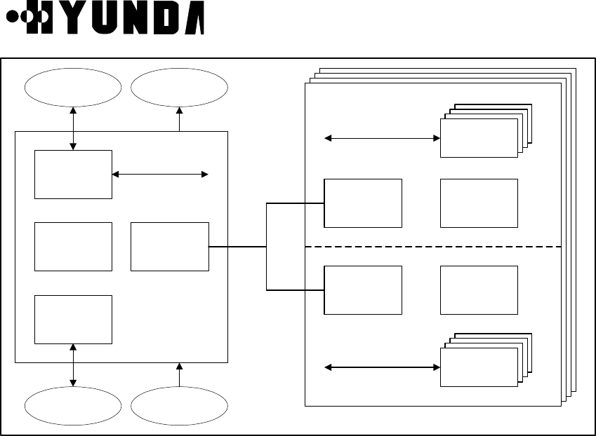
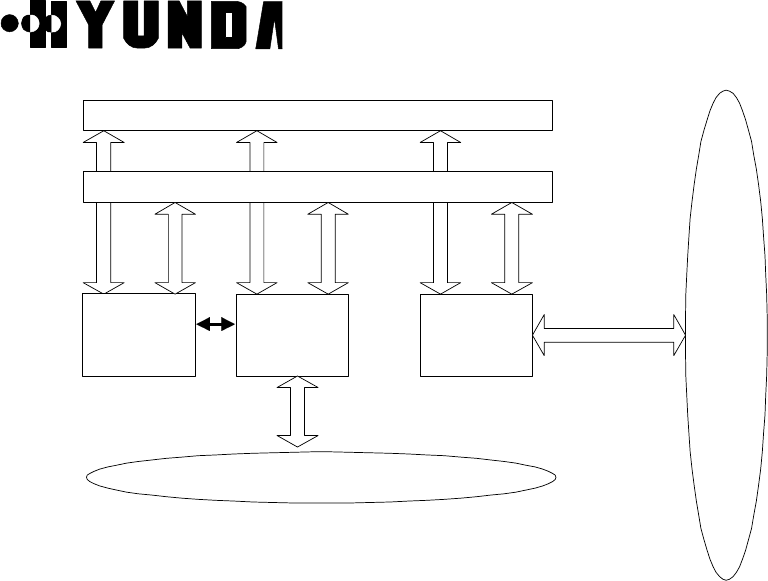
Hardware structure of BSC is shown in Fig.2.2 and traffic and data communication is
accomplished in connection with BTS, CCP, CSB, TSB, BSC-GPS & ACP and BSM with
placing LCIN and GCIN as a Packet Router. For interconnection between BSC, extension
of system is possible using private Router (HRNA-A2). Therefore, structure is designed
that soft handoff is possible between BTSs controlled by different BSCs
BSM
T1
T1
T1
BSC-GPS
HICA HRNAHRNA
HRNA
HICA
HRNA
HRNA
HRNA
HRNA HRNA
HRNA
HRNAHRNA
LCIN
ACP
MCDA CIFA
CCP
MCDACIFA
CSB
CKD
0 1 31
V
S
O
A
V
S
O
A
V
S
O
A
V
S
I
A
SYSTEM BUS
ST-BUS
TSB
GCIN
IPC IPC
IPC
IPC
IPC
To/From MSC
To/From
BTS0
~
BTS59
T1
IPC
Figure 2.2 H/W Structure of BSC

User’s Manual
PROPRIETARY & CONFIDENTIAL 2-6
2.2.2 Structure of Subsystem
2.2.2.1 LCIN (Local CDMA Interconnection Network)
LCIN receives Packet Data transmitted by each subsystem connected to BSC and routes
the Packet Data to destination address that are added in overhead of Packet.
(1) Functions of LCIN
• CDMA Traffic Information Routing between BTS and TSB
• Information Routing between BTS, CCP.
• Internal information Routing among TSB, CCP, CSB, TFGA-A1 and ACP
(2) H/W Structure of LCIN
After LCIN converts Packet Data which are inputted by each subsystem in BSC to
16-bit parallel data, analyzes Packet Address and converts them again to Serial data
via internal Routing and routes them to corresponding subsystem. LCIN consists of
HICA-A2, HRNA-A2, HNTA-A2 and backboard CHBB-A1 card.
1) HICA-A2 (High-performance IPC Control Board Assembly-A2)
HICA-A2 performs network management functions of LCIN that is made up of
nodes providing communication path between processor of BSC and BTS.
For management of communication network, LCIN have control and maintenance
channel (M-BUS) responsible for fault processing and node status monitoring and
communication channel (U-Link) with other processor. HICA-A2 generates BUS
arbitration control signal between nodes of D-BUS and exchanges common bus for
data of each node. HICA-A2 performs each PBA’s status management and
maintenance of LCIN block, and status management and maintenance of Link.
2) HRNA-A2 (High performance IPC Routing Node Assembly-A2)
HRNA-A2 have 8 Nodes. It is a PBA having the function of node that is basic unit of
IPC (Inter Processor Communication) in LCIN. HRNA-A2 is an interface board by
which each subsystem can be accessed to LCIN. After converting the packet data
that are inputted through RS-422 parallel interface, it outputs the converted data on
packet bus (D-BUS) of LCIN according to the routing control signal of HICA-A2.
HRNA-A2 performs that extracts 3 bytes destination address of Packet Data that is
loaded on D-Bus and accepts the packet only if the compared result of destination
address of Packet Data with node address of itself are equal, then converts it to
serial type and transmits it to each subsystem.
User’s Manual
PROPRIETARY & CONFIDENTIAL 2-7
HRNA-A2 performs the functions that receives control command from HICA-A2 and
reports the status of HRNA-A2 using dualized serial control bus (M-BUS).
HRNA-A2 has the functions that detects various fault per node and D-BUS fault
occurs in operation, and reports detected faults to HICA-A2 through M-BUS.
HRNA-A2 performs fault recovery functions by initializing fault detected node and
switching of D-BUS.
3) HNTA-A2 (High Performance IPC Node & T1 trunk interface Board Assembly-A2)
HNTA-A2 is used for linking T1 trunk in LCIN. BSC and BTS are accessed each
other through Digital Trunk and HNTA-A2 performs link functions of T1 Trunk Line.
HNTA-A2 performs functions of Node and link of Trunks simultaneously, and have 8
node and 8 T1 digital trunk interface.
HNTA-A2 performs the functions that receives control command from HICA-A2
through M-BUS and exchanges packet between node through D-BUS.
HNTA-A2 performs the functions that tries to recover by fault detection of D-BUS
and monitors and reports the status of Trunk.
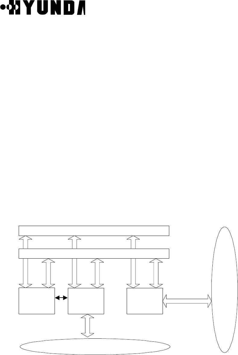
(3) Structure Diagram of LCIN
• LCIN consists of Routing functions based on BSC unit.
• LCIN consists of BTS link interface functions using T1 Trunk Line.
The following Fig.2.3 describes structure diagram of LCIN
HICA-A2HICA-A2 HRNA-A2HRNA-A2
T1
Data Bus (D-Bus)Data Bus (D-Bus)
Maintenance Bus (M-Bus)Maintenance Bus (M-Bus)
U-LinkU-Link
HNTA-A2HNTA-A2
BSC Blocks & UnitsBSC Blocks & Units
BTSBTS
u-link
Figure 2.3 Structure Diagram of LCIN

User’s Manual
PROPRIETARY & CONFIDENTIAL 2-8
(4) Address System
LCIN uses 3 byte address system enough to process traffic resources in BS (BTS &
BSC).
2.2.2.2 TSB (Transcoding & Selector Bank)
(1) Functions of TSB
• CCP by MSC allocates resources when call setup
• provides information about code transition by mobile and registration in the process of
call processing
• removes vocoder when call releases
• corresponding Card to Channel Element of BTS
• performs vocoder functions of voice
• performs functions of Rate Adaptation of Data and Coder/Decoder
• performs function of Selection for Soft-Handoff
• performs Power Control functions (Forward Power Control & Open Loop Power
Control)
(2) Hardware structure of TSB
• TSB consists of VSIA-C1 connected to LCIN and VSOA-A1 mounted with vocoder
• has 92 Transcoding Channel per TSB 1Unit (T1)
• VSIA-C1 performs functions that receives serial Packet data inputted from LCIN,
converts to parallel data, transmits to VSOA-A1 mounted with vocoder, receives data
vocoded in VSOA-A1 and converted to PCM type through ST-BUS, makes data
multiplex and transmits to MSC.
• VSOA-A1 is mounted with 12 vocoder performs functions that converts QCELP Packet
Data to PCM Voice Code and PCM Voice Code to QCELP Packet Data.
(3) Structure Diagram of TSB
The following Fig.2.4 describes structure diagram of TSB
User’s Manual
PROPRIETARY & CONFIDENTIAL 2-9
ROUTER
I/F MCU
AM29240
DSP
Module
DSP
Module
DSP
Module
DSP
Module
ROUTER
I/F MCU
AM29240
DSP
Module
DSP
Module
DSP
Module
DSP
Module
ROUTER
I/F
CPU
MC68360
T1
HDLC
MSC ALM
LCIN CKD
2 T1
ST-BUS
ST-BUS
ST-BUS
RS-422 VSIA-C1
VSOA-A1
Figure 2.4 Structure Diagram of TSB
2.2.2.3 CCP (Call Control Processor)
(1) Functions of CCP
• performs all of call processing related control functions of BSC
• exchanges CDMA related information among BTS, TSB and MSC
• controls Soft-Handoff and Hard-Handoff
• supports Paging
• controls overload and manages TSB
(2) Hardware structure of CCP, CSB
CCP consists of main processor MCDA and CIFA responsible for inter-processor
communication with HRNA in LCIN.
When using No.7 Signaling mode, CCP system is connected to CSB block through
CIFA-A1 via LCIN block and CSB block transfers this message to MSC through Trunk
after converting this message appropriate for No.7 Protocol.
1) MCDA (Main Control Duplication Assembly)
MCDA communicates with CIFA-A1 using MPS-bus. It is responsible for
communication with dualized block. If Power of MCDA is ON, Booter operates, and

User’s Manual
PROPRIETARY & CONFIDENTIAL 2-10
MCDA determines whether active or standby of itself through S channel of MFP in
result of negotiation with other MCDA and requests loading. If MCDA operates
normally after OS Loading, MCDA controls call processing and manages Selector.
2) CIFA-A1 (CIN Interface Board Assembly)
CIFA-A1 is an interface board responsible for communication with external and has
functions of MPS-bus link and direct DATA communication with CIN block.
For connection with LCIN, CIFA-A1 transmits and receives control information using
Address Decoding & Zero insertion/deletion, CRC generation and check function
through HDLC Protocol.
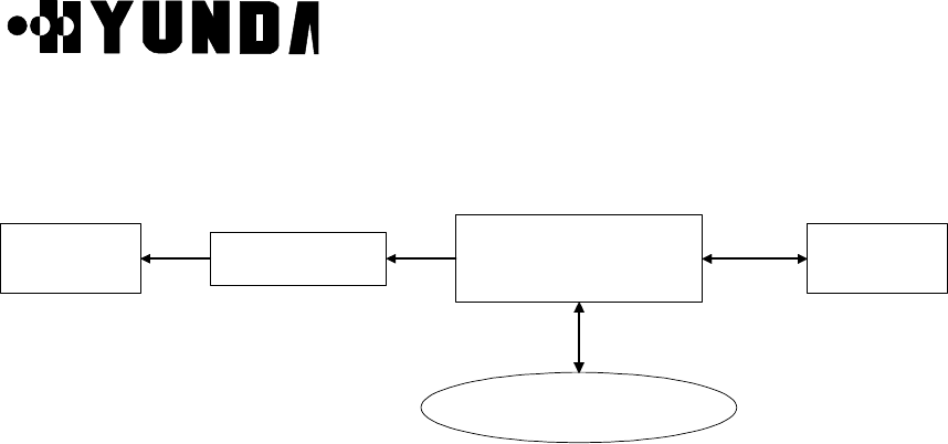
3) Structure Diagram of CCP, CSB
The following Fig.2.5 describes structure of CCP
LCIN
VSIA-C1
CIFA-A1MCDA
MSC
Figure 2.5 Structure of CCP
2.2.2.5 BSC-GPS/CKD (Clock Distributor)
(1) Functions of BSC-GPS/CKD
• BSC-GPS block is located in CMNR of BSC (Base Station Controller). When 1PPS and
10MHz from GBSU-A1 (GPS) are inputted to TFSA-A1, then it converts and distributes
them into clock necessary in BSC, and provides them through TFDA-A1 to TSB and
LCIN. Number of providing clocks is 16 in minimum and 32 clocks in maximum.
• Distributed Clock : 4.096MHz, 2.048MHz, 1.544MHz, FP (8KHz), FOI (8KHz), 50Hz,
1Hz
(2) Hardware structure of BSC-GPS/CKD
BSC-GPS/CKD consists of GPS Receiver, TFSA-A1 that receives clock, Clock
User’s Manual
PROPRIETARY & CONFIDENTIAL 2-11
generator (TFGA-A1) and Clock distributor (TFDA-A1).
The structure Diagram of CKD is shown in Figure 2.7.
GPS
RECEIVER-A TFSA-A1 TFGA-A1
BSM
T
F
D
A
TSB or CIN
16CLK PORT
HDLC
RS-422
TOD
Clocks
RS-422
Figure 2.7 Structure Diagram of CKD

User’s Manual
PROPRIETARY & CONFIDENTIAL 2-12
2.2.2.6 ACP (Alarm Control Processor)
(1) Structure and Functions of ACP
ACP block is located in BSC (Base Station Controller) and has functions of collecting
alarm sources of each subsystem by H/W and reporting to BSM by S/W. This block is
mounted one per one BSC and one ACP block is mounted on a ACPA-A1 board and
can monitor 26 alarm ports in maximum. Each alarm port is connected to each
subsystem of BSC more than one and monitors OFF-FAIL of important board and
power module.
If system extends and number of alarm port is increased, additional ACP blocks can be
mounted.
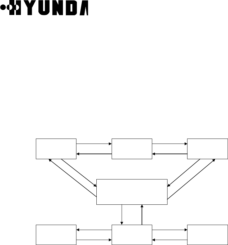
(2) Structure Diagram of ACP
The following Fig.2.8 describes structure diagram of ACP
ACPA-A1 BSM
LCIN
CCP LCIN CKD TSB
Alarm Information
IPC-HDLC
Figure 2.8 Structure Diagram of ACP
2.2.2.7 GCIN (Global CDMA Interconnection Network)
GCIN receives Packet Data transmitted by each subsystem connected to GCIN . GCIN
also receives Packet Data transmitted from a LCIN to other LCIN. GCIN routes the Packet
Data to destination address which are added in overhead of Packet.
(1) Functions of GCIN
• CDMA Traffic Information Routing between LCINs
• Information Routing between LCINs and BSM.

User’s Manual
PROPRIETARY & CONFIDENTIAL 2-13
• Internal information Routing among TFSA-A1, HICA-A2 , BSM.
(2) H/W Structure of GCIN
GCIN converts Packet Data which are inputted by each link from LCIN or subsystems
in GCIN to 16-bit parallel data, GCIN analyzes Packet Address and converts them
again to Serial data via internal Routing and routes them to corresponding subsystem
or links. GCIN consists of HICA-A2, HRNA-A2, and backboard HSBB-A1 card.
1) HICA-A2 (High-performance IPC Control Board Assembly-A2)
HICA-A2 performs network management functions of GCIN which is made up of
nodes providing communication path between processor of BSC and BTS.
For management of communication network, GCIN has control and maintenance
channel (M-BUS) responsible for fault processing and node status monitoring and
communication channel (U-Link) with other processor. HICA-A2 generates BUS
arbitration control signal between nodes of D-BUS, common bus for data exchange
of each node. HICA-A2 performs each PBA’s status management and maintenance
of LCIN block, and status management and maintenance of Link.
2) HRNA-A2 (High performance IPC Routing Node Assembly-A2)
HRNA-A2 has 8 Nodes. It is a PBA having the function of node which is basic unit of
IPC (Inter Processor Communication) in GCIN. HRNA-A2 is an interface board by
which each subsystem can be accessed to GCIN. After converting the packet data
which are inputted through RS-422 parallel interface, it outputs the converted data
on packet bus (D-BUS) of GCIN according to the routing control signal of HICA-A2.
HRNA-A2 performs that extracts 3 bytes destination address of Packet Data which
are loaded on D-Bus and accepts the packet only if the compared results of
destination address of Packet Data with node address of itself are equal, then
converts it to serial type and transmits it to each subsystem.
HRNA-A2 performs the functions that receives control command from HICA-A2 and
reports the status of HRNA-A2 using dualized serial control bus (M-BUS).
HRNA-A2 have the functions that detects various fault per node and D-BUS fault
occurs in operation, and reports detected faults to HICA-A2 through M-BUS.
HRNA-A2 performs fault recovery functions by initializing fault detected node and
switching of D-BUS.
(3) Structure Diagram of GCIN
• GCIN consists of Routing functions between LCINs.
• GCIN consists of Routing functions between subsystems in GCIN.
The following Fig.2.9 describes structure diagram of GCIN
User’s Manual
PROPRIETARY & CONFIDENTIAL 2-14
HICA-A2HICA-A2 HRNA-A2HRNA-A2 T1/E1
Data Bus (D-Bus)Data Bus (D-Bus)
Maintenance Bus (M-Bus)Maintenance Bus (M-Bus)
U-LinkU-Link
HNTA-A2/HNTA-A2/
HNEA-A2HNEA-A2
BSC Blocks & UnitsBSC Blocks & Units
BTSBTS
u-link
Figure 2.9 Structure Diagram of GCIN
(4) Address System
GCIN uses 3 byte address system enough to process traffic resources in BS (BTS &
BSC).

User’s Manual
PROPRIETARY & CONFIDENTIAL 2-15
2.3 S/W Structure and Function
2.3.1 Overview
Software of CCP and TSB consists of an operation and maintenance Software and a
control and resource management Software of each subsystem.
Software of BSM can largely be divided into an operation function and a general function.
The operation function consists of a software taking charge of system loading, system
structure management and performance management and a software taking charge of
maintenance function that detects, isolates and recovers abnormally-running device.
The general function consists of software taking charge of data communication function,
data management function, and manager link function.
2.3.2 Structure
2.3.2.1 CCP Software
(1) CCOX (Call Control eXecution)
• Origination and Termination call processing processed by the unit of Process CCOX
registers and manages their call by the unit of Process and releases Process by Call
Release function.
• Origination call processing, in case of receiving Call Request of Handset from BS,
allocates selector and ensures traffic channel by using resource allocation function
and requests Call Setup to MSC. If the approval from MSC is identified, Call Setup of
Origination call processing is completed
• Termination call processing, in case of receiving Paging Request from MSC, allocates
selector and ensures traffic channel by using resource allocation function and
completes Call Setup of termination call processing
• Origination and Termination Call Release are performed in case of requesting Call
Release by telephone network subscriber or Handset, and cause Call Path and
wireless channel and inform it of data processing function
• also, performs designated path CALL SETUP and CALL TRACE function

User’s Manual
PROPRIETARY & CONFIDENTIAL 2-16
(2) CDAX (CCP Database Access eXecution)
• It is a library that supplies various functions able to read, write and access the
operation information in CCP and the PLD saving configuration information.
(3) CRAX (CCP Resource Allocation eXecution)
• initialization of configuration information of CCP
• statistics library supply
• available call resource library supply
(4) CMMX (CCP Measurement Manager eXecution)
This block has a function for measurement and statistics processing.
• statistics data collection & measurement
• statistics data report
• linking with call processing S/W & library call
• statistics count decision (event collection /accumulation/totalization)
(5) CDIAX (CCP DIAgnosis eXecution)
It consists of diagnostic function and performance drop prevention function by
diagnosis in initialization and system operation
• diagnosis for process, Device, path
• automatic diagnosis for vocoder and link
(6) CSHX (CCP Status Handling eXecution)
It consists of functions for state management of system
• processor state checking
• management of vocoder and link state
• information supply for available resource
(7) CRMX (CCP Resource Management eXecution))
It consists of functions for resource configuration management
• configuration control of resource
• resource data processing by MMC
• common data (BCP&CCP Common Data) loading and data display
(8) CPLX (CCP Process Loader eXecution)
It consists of initial Loading and Loading function in operation.
• Start and Restart of initial system

User’s Manual
PROPRIETARY & CONFIDENTIAL 2-17
• Start and Restart of process
• Stand-by Loading
• initialization (data initialization, process initialization and state identification)
2.3.2.2 Software Structure of CCP
The following Fig.2.10 describes S/W structure of CCP
CCOX CRMX
CDAXCSHX
CDIAX
CMMX
CPLX
CRAX
PLD
Figure 2.10 S/W Structure of CCP
2.3.2.3 TSB S/W Structure
TSB S/W (from now on, SVPX) is the S/W block driven over VSOA board, since two
Processors exist in one board, each Processor process six channels. SVPX processes
traffics and signals coming from Mobile, CE and CCP. SVPX consists of following Tasks.
[Refer to Fig.2.11]
User’s Manual
PROPRIETARY & CONFIDENTIAL 2-18
Vocoder
Call proc Task
Layer2 Task
29K Driver
Main Task
CCP msg
routine
Rx Int Server
Handoff Task
Tx Int Server
Power Control
Task
Voice
Signal
BTS
(CE)
CCP
Figure 2.11 TSB S/W Structure
(1) 29K Driver
As initial Task after SVPX is loaded , it initializes processor and plays an interface role
between AP and Devices. Other tasks are processed over this Driver
(2) Main Task
If main task takes over control from Driver, it initializes Queue and Vocoder state and
generates task and initializes it.

User’s Manual
PROPRIETARY & CONFIDENTIAL 2-19
(3) Rx Interrupt Server
Traffic Frame transmits and receives one frame every 20msec per call. Some of
reverse frame coming from Mobile every 20msec contain a vocoded voice data and a
CAI (Common Air Interface) message for call processing.
The Voice data is transmitted into Vocoder, the CAI message is transmitted into
Callproc Task, and control message coming from CE is also transmitted into Callproc
Task.
Rx Interrupt server estimates frame quality by Quality Metric value and transmits that
into Reverse Power Control, practices Rx Frame Selection in case of handoff.
(4) Tx Interrupt Server
It makes Forward Frame every 20ms and also transmits that. In case of handoff, it
multicasts to maximum three BTSs.
(5) Layer2 Task
It processes ACK_SEQ, MSG_SEQ and ACK_REQ field of respective message to
accomplish reliable message exchange between Mobile, CE and BS.
It processes Ack of a receiving message and retransmits a transmitting message in
case of necessity
(6) Callproc Task
It performs appropriate call processing according to signal from Mobile, CE and CCP.
(7) Handoff Task
In case of processing control message related to Handoff, it is according to handoff
decision of CCP. And it performs corresponding handoff type. Handoff type is largely
divided into SOFTER H/O, SOFT H/O and HARD H/O.
(8) Power Control Task
According to PMRM (Power Measurement Report Message) or Erasure Indicator Bit
coming from Mobile, it performs Forward Power Control indicating Forward Traffic
Channel Gain adjustment into CE every 20ms and indicates Reverse Traffic Power
adjustment of Mobile through CE every 1.25ms, after checking FER of Reverse Traffic
Frame
2.3.2.4 BSM Software

User’s Manual
PROPRIETARY & CONFIDENTIAL 2-20
(1) CDMX (Configuration Data Manager eXecution)
1) Block Summary and Working Function
A CDMX block manages some data such as operation parameter requested to
perform Inherent function of BTS and BSC subsystems and hardware placement
information. Also, the CDMX receives a command through manager link in BSM to
supply coherence of data alternation and adaptation and processes that. And the
CDMX saves the processed result in database and reports it to manager.
The CDMX consists of a CDM_interface unit which makes corresponding function
work by analyzing the message received from UIM (User Interface Manager), a
PLD_access unit for PLD access and a Data_send unit for data transmission into
subsystem. After classifying the received message, The CDMX process the
command and sends the processing result to UIM
2) Block Flowchart
The following Fig.2.12 describes CDMX block flowchart.
a. informs BIM that CDM is in normal state.
b. sends the processing results received from UIM for mamager's command for
data processing.
c. In case of Data Change Request, send data to the CRM and receive result.
d. receives a PLD Change Request Message from the APP
e. sends processing result to the APP.
BIM UMH BSM APPs
CDMCRM UIM
PLD
a
c
e
b
d

User’s Manual
PROPRIETARY & CONFIDENTIAL 2-21
Figure 2.12 CDMX block flowchart

User’s Manual
PROPRIETARY & CONFIDENTIAL 2-22
(2) SLX (System Loader Execution)
1) Block Summary and Working Function
During initialization of CCP and ACP subsystem, a SLX loads application blocks
performed in CDMA system into CCP and ACP. The SLX renew database to
manage loading history according to location information and state of system loaded
in case of performing loading of each subsystem.
Function related to CCP out of Subsystem Restart and Block Switch function by
MMC is processed by CPL. Function related to BCP, SIP and SVP is performed by
inter-working with CPL, Booter of BCP, SIP, SVP, and PL. It supplies a loading
history by MMC for manager.
Also, The SLX removes specific block out of application blocks performed in each
subsystem or adds application block to specific subsystem.
2) Block Flowchart
The following Fig.2.13 describes SLX block flowchart.
CDM UIM FLM
SL
CBOOT ACP BOOTCPL
Figure 2.13 SLX Block Flowchart
(3) SMMX (Statistics Measurement Manager eXecution)
1) Block summary and working function
A SMMX block requests BSC system to measure performance data. The SMMX
processes statistics of the measured data, saves it and outputs it. Also, the SMMX
outputs statistics report output according to user’s request by using a periodically
User’s Manual
PROPRIETARY & CONFIDENTIAL 2-23
receiving performance data in BSC system. The SMMX can stop and start the
measurement on system.
Software unit of SMM block consists of Command Processing Part, Signal Message
Format Processing Part, Screen Output Format Part, and Database Processing
Part. Command Processing Part processes command inputted by manager. Signal
Message Format Processing Part formats the signal message which will be
transmitted. Signal Message Unformatting Processing Part unformats the signal
message. Screen Output Format Part outputs a statistical data on the BSM
message output window. Database Processing Part manages the statistical
database.
2) Block Flowchart
The following Fig.2.14 describes SMMX block flowchart.
SMM block
Message Queue
BIM block
Message Queue
Message Queue
DCI
block UIM block
Statistics Database
Memory Map
Figure 2.14 SMMX Block Flowchart

User’s Manual
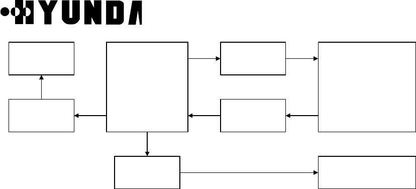
PROPRIETARY & CONFIDENTIAL 2-24
(4) FLMX (FauLt Management eXecution)
1) Block Summary and Working Function
A FLMX block has functions which process a fault and alarm message caused at
BTS and BSC system. The received fault message of the FLMX block is related to
the Fault detected by test and maintenance function of BTS and BSC system. If the
state of fault is serious (i.e. fault classified into alarm), the FLMX informs manager of
that by driving a message and an audible and visible alarm after deciding
corresponding alarm grade. If the FLMX receives a command from manager, the
FLMX initializes the database that has the current state information of alarm. Also
the FLMX initializes a database for visible alarm which appears at the terminal and
a database for audible alarm.
2) Block Flowchart
The following Fig.2.15 describes FLMX block flowchart.
a. receipt of manager’s command from UIM block and report of result.
b. report Alarm and Fault processing result to OFH block .
c. send signal to STM block.
d. receipt of GPS state alarm from the SCM block
e. receipt of H/W alarm from ACP block
f. receipt of alarm from CIN
g. receipt of LCIN S/W alarm from CCP
h. receipt of BTS S/W alarm from BMP
User’s Manual
PROPRIETARY & CONFIDENTIAL 2-25
FLM
UIM OFH
SCM
BMPGCIN
ACP
CCP
a b
c d
eg fh
STM
BSMBSM
BSCBSC Micro-BTSMicro-BTS
Figure 2.15 FLMX Block Flowchart
(5) TSMX (TeSt Manager eXecution)
1) Block Summary and Working Function
A TSMX block tests for the fault diagnosis of BTS and BSC system. The TSMX
consists of a unit which analyzes command of manager, a unit which packs to send
the analyzed message to corresponding subsystem, a unit which analyzes a
execution result transmitted from subsystem and a unit for accessing database.
Also, the TSMX consists of a Temporary Processor executed by manager’s request
and a Permanent Processor which performs data management and processing of a
receiving message.
2) Block Flowchart
The following Fig.2.16 describes TSMX block flowchart.
a. Test Request for DEVICE
b. Response for DEVICE Test Request
c. Test Request for BTS LINK and Channel Element
d. Response for BTS LINK and Channel Element Test Request
e. Test Request for Vocoder
f. Response for Vocoder Test Request
g. Request for virtual call test and BTS output adjustment
User’s Manual
PROPRIETARY & CONFIDENTIAL 2-26
h. Virtual test and BTS output adjustment result
i. Virtual Call Set up Request and BTS output adjustment Request
j. Virtual Call Set up and BTS output adjustment result
k. BTS output adjustment Request
l. BTS output adjustment result
m. antenna test, remote call test and test terminal operation information output
Request
n. antenna test, remote call test result and test terminal operation information
TSMX
BCOX BTCA
TMNXCDIAX
CCOX
BDIAX
a b
c
d
e
f
g
h
i
j l
k
m
n
Figure 2.16 TSMX block flowchart
(6) STMX (Status Management eXecution)
1) Block Summary and Working Function
A STMX block displays the things (which result from monitoring state of main
processors in BSC system and searching each processor and device state and call
resource state of BSC and BTS system, in case of manager’s demand) on
manager’s screen .
The STMX also manages and maintains BTS and BSC system or state of device
with interworking with the structure management and the fault management
function.
There are some functions in STMX, a monitoring function of BSC main processor

User’s Manual
PROPRIETARY & CONFIDENTIAL 2-27
state, a processor and device state search function of BTS and BSC by manager’s
request, a overload Control function and a call resource state search function of
GUI (Graphic User Interface) screen.
The function monitoring Processor state is to monitor action state of these
subsystem by polling CCP, ACP, HICA, TSGA processor periodically. The
processor and device state search function of BTS and BSC by manager’s request
has a responsibility for request and output for device state which each subsystem is
managing now.
The overload control function is to output overload state of CCP and BCP and
change overload critical value of CCP and BCP.
The call resource state search function of GUI screen is ,when manager is on call
resource state screen, to reflect it on screen by searching current accurate call
resource state periodically.
2) Block Flowchart
The following Fig.2.17 describes STMX block flow chart.
Figure 2.17 STMX Block Flowchart
a Monitoring and Request of ACP Processor State
b Report of ACP Processor State
c Monitoring of CCP Processor State, State Request of processor and devices,
Overload Control and Report of State
d Monitoring of CCP Processor State, State Report of processor and devices,
Report of Overhead State
e Monitoring and Request of TSGA Processor State , Request of TFDA State
f Report of TSGA Processor State , Report of TFDA State
g Monitoring of GCIN/LCIN Processor State, Request of GCIN/LCIN/BIN
Processor and Node State and Request of Active Side Switch
h Report of GCIN/LCIN Processor State, Report of GCIN/LCIN/BIN Processor
and Node State, Report of Active Side Switch

User’s Manual
PROPRIETARY & CONFIDENTIAL 2-28
i Request of TFSA and GPS Processor State
j Report of TFSA and GPS Processor State
k Request of SACA Processor State
l Report of SACA Processor State
m Request of BTS Processor and device State and Request of Overload Control
and State
n Report of BTS Processor and device State and Report of Overload State
(6) DCIX (Data Communication Interface eXecution)
A DCIX block supplies a path for transmitting/receiving a management information
between application blocks in BSM and other subsystems in BTS and BSC system,
and communicates with other system by HDLC.
Communication with other system is accomplished through RS-422 at the speed of
2.048Mbps. and a data link uses point-to-multipoint method.
The DCI block is generated by BIM block, initializes a necessary data for setting up a
data link between other subsystems and must be in a standby state to set up the data
link with other subsystem .
Application block in BSM (in case of establishing data link) or DCI block (in case of
receiving message from other subsystem) must perform procedure which processes
this message.
(7) DBHX (DataBase Handler eXecution)
1) Block Summary and Working Function
A DBHX block establishes, initializes and manages a database which application
block in BSM need.
The DBHX block consists of a DBD (DataBase Definition) software unit and a
DBM (DataBase Management) software unit.
The DBD function is to generate a database through setting up relation between
each entities to remove overlap properties of data which each application block
needs.
The DBM supplies a function which ,in case of using a database of a application in
BSM, processes the data efficiently and exactly.
User’s Manual
PROPRIETARY & CONFIDENTIAL 2-29
2) Block Flowchart
The following Fig.2.18 describes DBHX block flow chart.
DBH blockBIM block Message Queue UIM block
BSM DATABASE
Memory Map
Figure 2.18 DBHX Block Flowchart
(9) UIMX (User Interface Manager eXecution)
1) Block Summary and Working Function
A UIMX block performs all functions related to window such as creation and removal
of window and event processing, and supplies a function which outputs a system
state and information as to alarm and statistics with simply and logically
recognizable graphic type
Also, the UIMX processes events caused from manager and displays a information
supplied from each application block on manager’s terminal screen with text or
graphic. Also, the UIMX block supplies a command input type about GUI (graphic
user interface) such as menu and dialogue box .
After formatting a voluntary message received from system (i.e. fault and alarm
message, state, statistics report and test result) , the UIMX block displays that on
the system display window.
2) Block flowchart
The following Fig.2.19 describes UIMX block flowchart.
User’s Manual
PROPRIETARY & CONFIDENTIAL 2-30
U
I
M
BIM
Message
Queue
COH
APP
fork
read
fork
write
write
pipe (r/w)
Figure 2.19 UIMX Block Flowchart
(10) COHX (COmmand Handling eXecution)
1) Block Summary and Working Function
A COHX block performs a syntax and meaning analysis function of input command
and a execution control function. The Syntax analysis checks the accuracy of the
grammar of a inputted command and the Meaning analysis checks the meaning of
command and the range of parameter.
If format error occurs on analysis procedure, Command Analysis block supplies the
location of error, the kind of error and the information for error correction.
On the other hand, if analysis result of command prove to be out of error, the
command drives application function to perform the command, receives execution
result from application function and displays it on display window by transmitting it
into UIM block.
2) Block Flowchart
The following Fig.2.20 describes COHX block flowchart.
User’s Manual
PROPRIETARY & CONFIDENTIAL 2-31
CDD
file
COHCOH Application Blocks
(FLM, SL, STM,
TSM, CDM, SMM)
CDD
file
input command
output command
fork
pipe
fork
pipe
Figure 2.20 COHX Block Flowchart
(11) BIMX (BSM Initialization and Maintenance eXecution)
1) Block Summary and Working Function
A BIMX block is first initiated at the BSM software. Also, the BIMX block is initiated
in case of booting of BSM system or by manager. In case of initialization of BSM,
BIM initializes all necessary internal data of BSM, executes a permanent process
block and initializes a necessary IPC function for data communication between
blocks in BSM.
If all block is run, BIM monitors the action state of permanent process. while, If the
action of these process is stopped abnormally, BIM takes an appropriate recovery
procedure and reports this fact to manager.
2) Block Flowchart
The following Fig.2.21 describes BIMX block flowchart.
a. SCM drive and state management by BIM
b. DCI drive and state management by BIM
c. BSM application- part drive and state management by BIM
d. UIM drive and state management by BIM
e. LJH drive and state management by BIM
f. UIM drive and state management by BIM
g. UMH drive and state management by BIM
User’s Manual
PROPRIETARY & CONFIDENTIAL 2-32
B I M
SCM
DCI
BSM Ap-part
SL,CDM
SMM, STM
TSM, FLM
etc.
LJH
UIM
UMH
Figure 2.21 BIMX Block Flowchart
(12) UMHX (Unsolicited Message Handler eXecution)
1) Block Summary and Working Function
In case of receiving a initial message from BTS or BSC system, a UMHX block
generates a corresponding application block for processing the message and let it
perform the requested application function.
After adding a corresponding permanent process ID to the received message, the
UMHX makes the corresponding process the message by transmitting it into a
message Queue. The UIM block is driven as a permanent processor by BIM block.
After reporting current state to BIM block, if UIM receives processors of STM, SMM,
TSM, FLM and SL block from BIM block, before receiving a system output message
corresponding to STM, SMM, TSM, FLM and SL block, after UMH block prepares
for receiving the system output message of other subsystem, when a corresponding
message is delivered, the UMH block analyzes Signal_id and performs a function
which generates a corresponding block in BSM.
2) Block Flowchart
The following Fig.2.22 describes UMHX block flowchart.
a. BIM reports UMH drive and drive state to the BIM
b. receipt of unidentified initial message
c. Temporary processor generation and message transmission and management

User’s Manual
PROPRIETARY & CONFIDENTIAL 2-33
d. permanent processor id management and corresponding message transmission
e. transmit UMH state information into the UIM
B I M
DCI
Permanent
Processor
(SL, SMM,
STM, TSM,
FLM)
Temporary
processor
SL, CDM
UIM
UMH
a
c
e
d
b
Figure 2.22 UMHX Block Flowchart
(13) LJHX (Long-term Job Handler eXecution)
1) Block Summary and Working Function
A LJHX block performs a application function by generating a application block
which requires a long time requested by manager and manages the state of this.
The LJH block is driven as a permanent processor by BIM block. And after reporting
current state to BIM block, the LJH block prepares for generating a processor which
requires the long time requested by manager.
If the LJHX block receives a processor performed for long time by manager’s
request, the LJHX performs a function which generates a corresponding block in
BSM by analyzing the corresponding command
2) Block Flowchart
The following Fig.2.23 describes LJHX block flowchart.
User’s Manual
PROPRIETARY & CONFIDENTIAL 2-34
BIM
Message
Queue
JH block
Message
Queue
Message
Queue
Message
Queue
Manager request
block
UIM block
Figure 2.23 LJHX Block Flowchart
(14) SCMX (System Clock Manager eXecution)
1) Block Summary and Working Function
A SCMX block receives periodically TOD (Time Of Day) from GPS, sets up BSM
time and reports that to application block which requires TOD. The SCM block is
driven as a permanent processor by BIM block .
After reporting current state to BIM block, the SCM block prepares for receiving
TOD
Clock from GPS every two seconds. In case that the receiving Clock is out of error,
the SCM block compares it with current BSM System Clock.
If range of error is within 3 second, the SCM block don’t reset the BSM System
Clock, and If range of error is over 3 second, the SCM block resets the BSM System
Clock.
2) Block Flowchart
The following Fig.2.24 describes SCMX block flowchart.
a. BIM control SCM drive and drive state
b. receive TOD Clock from GPS
c. transmit SCM state information into the FLMX

User’s Manual
PROPRIETARY & CONFIDENTIAL 2-35
BIM
GPS SCM
FLMX
a
b
c
Figure 2.24 SCMX Block Flowchart

User’s Manual
PROPRIETARY & CONFIDENTIAL 2-36
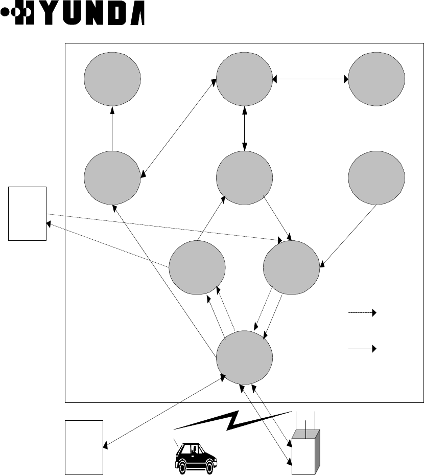
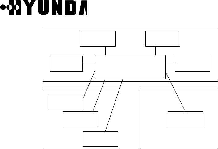
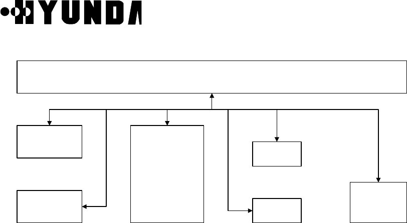
2.3.2.5 BSM Software Structure
The following Fig.2.25 describes BSM system s/w block structure
Figure 2.25 BSM System S/W Block Structure
User’s Manual
PROPRIETARY & CONFIDENTIAL 3-1
Chapter 3 BSM Operation & Administration
3.1 BSM Operation
3.1.1 Overview
This chapter describes the operations and functions of BSM (Base Station Manager) which
takes a part of system operation, administration, and maintenance of the subsystems of
BSC (Base Station Controller) in the mobile communication systems.
BSM provides GUI (Graphic User Interface) for OAM (Operation, Administration, and
Maintenance) which is status monitoring, performance measurement, statistics processing,
configuration management, alarm handling and so on. So, operators can use and
understand easily.
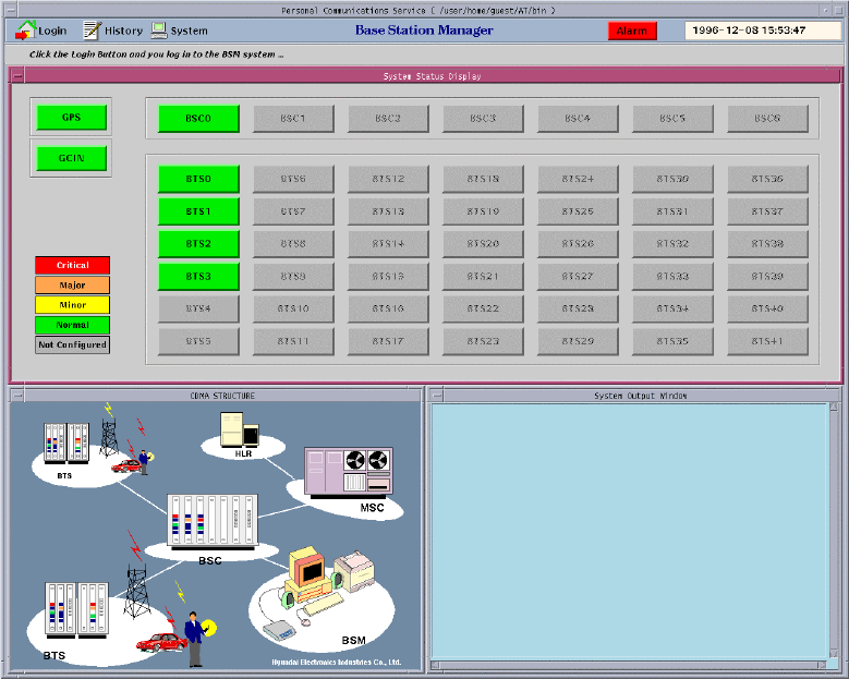
Figure 3.1 represents the initial display window of BSM when you start the BSM system up
in the workstation with the command, “bimx” without logging in it.
Figure 3.1 BSM Initial Display
User’s Manual
PROPRIETARY & CONFIDENTIAL 3-2
3.1.2 Main Display Structure
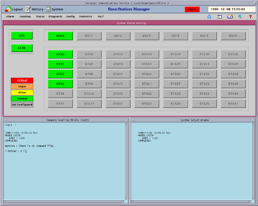
When you log in BSM with the specific user ID and password, the window such as Figure
3.2 is displayed.
Figure 3.2 BSM Main Display
3.1.3 Main Button
3.1.3.1 Operation by “Login” Button
User’s Manual
PROPRIETARY & CONFIDENTIAL 3-3
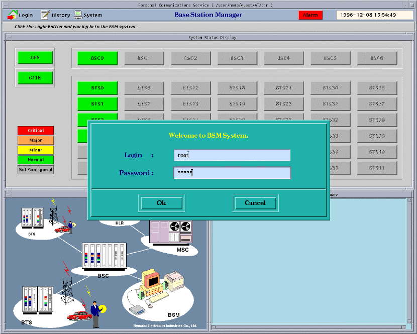
You can use the command for the CDMA System and service for the User by using login.
Figure 3.3 represents the login dialog box in BSM.
(1) Login Procedure
1) If you choose the "Login" Button in the main display window, "Login Dialog"
window is displayed.
2) You input the Login name and Password in the "Login Dialog" window and then
press the "OK" Button.
3) When the wrong spell is inputted or the login name or password is mistyped, the
login name or password, you can modify it using "Back space" key or "DEL" key.
Figure 3.3 BSM Login Window
User’s Manual
PROPRIETARY & CONFIDENTIAL 3-4
3.1.3.2 Operation by "History" Button
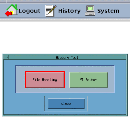
(1) If you choose the "History" button such as Figure 3.4 in the BSM Tile window, "History
Tool" window is displayed like Figure 3.5.
Figure 3.4 HISTORY Button
Figure 3.5 History Tool
(2) In the "History Tool" window, "File Handling" item functions "Display", "Print", and
"Delete" of the history file. The user of being good at UNIX system uses "VI Editor"
item to do them. First, if you press the "File Handling" button, "File Selection Dialog"
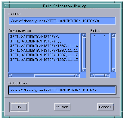
window such as Figure 3.6 displays.
User’s Manual
PROPRIETARY & CONFIDENTIAL 3-5
Figure 3.6 File Selection Dialog
(3) If you choose a certain date of date list in the "Directories" field of "File Selection
Dialog" window and then press the "Filter" button, "CHD" and "MHD" directories
display in the "Directories" field (Because both directories are operated in the same
manner, here deals with only the "CHD" directory).
(4) If you choose "CHD" directory and then press "Filter" button, a lot of files display in the
"Files" field, which is stored to command list by the elapsed time.
(5) If you choose a file of the list in the “Files” field of “File Selection Dialog” and press
“OK” button, the following window such as Figure 3.7 is represented. This list is sorted
to time.
Note – You can also use this shortcut: double-click the file name in the dialog box.
User’s Manual
PROPRIETARY & CONFIDENTIAL 3-6
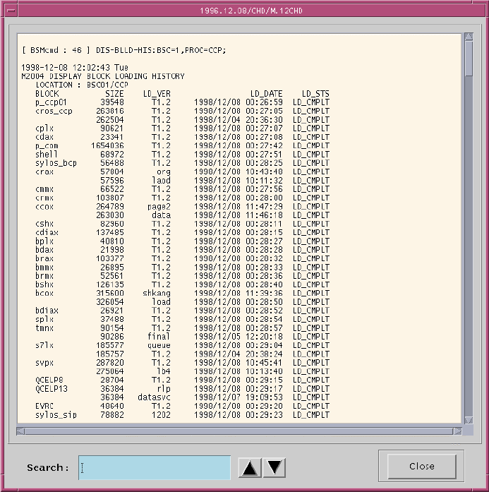
Figure 3.7 Result of “File Handling”
(6) Figure 3.7 shows the function of searching words. If you enter the word that you want
to search in the “Search : “ Text Field and push the Arrow Button () (or enter the
RETURN Key). Then the screen moves the location of the word to the first location
you want to search. It is possible to use the Down Arrow button or Return Key if you
want another locations of the word, The Up Arrow Button is used for searching the
word to upper field.
(7) If you choose the "Close” button, the window such as Figure 3.7 is closed.
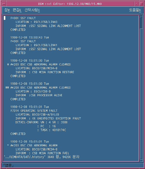
(8) If you choose "VI editor" button in the History Tool of Figure 3.5, "File Selection
Dialog" window such as Figure 3.6 displays and you can select the specific file in
User’s Manual
PROPRIETARY & CONFIDENTIAL 3-7
order to open it. After the procedures such as (3), (4), and (5) are processed, vi editor
window is created.
Figure 3.8 Result of “Vi Editor”
• VI Basic Commands
In the descriptions, CR stands for carriage return and ESC stands for the escape key.
:q!CR quit
/textCR search for text
(ex) /M5015 DISPLAY <enter>
^U ^D scroll up or down
^L clear and redraw window
User’s Manual
PROPRIETARY & CONFIDENTIAL 3-8
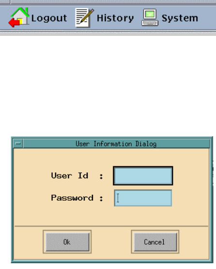
3.1.3.3 Operation by System Button
Pressing this button presented to Figure 3.9 enables the operator to control user related
information, command structures, peripheral devices of BSM. When you log in to the BSM,
you are limited the control authorization according to user’s level or grade.
Figure 3.9 System Button
To Start BSM System Manager :
• Click the System button in the BSM main window and User Information Dialog of
Fig.3.10 is displayed.
Figure 3.10 User Information Dialog
• Type the User ID and the Password in the corresponding field and then press “OK”
button
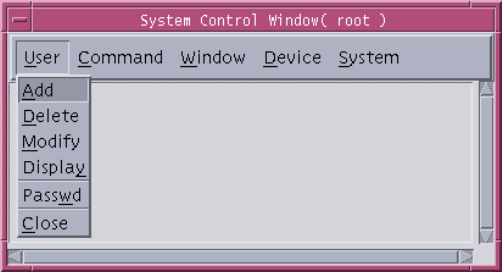
3.1.3.3.1 Operations by Super-user (root)
If you type “root” and its password in the User Information Dialog of Fig. 3.10 , the window
such as Figure 3.11 is displayed.
User’s Manual
PROPRIETARY & CONFIDENTIAL 3-9
Figure 3.11 System Control Window
3.1.3.3.2 User Menu
The only super-user can manage all grades of registered users. That is, the super-user
can add, register, modify, and delete user.
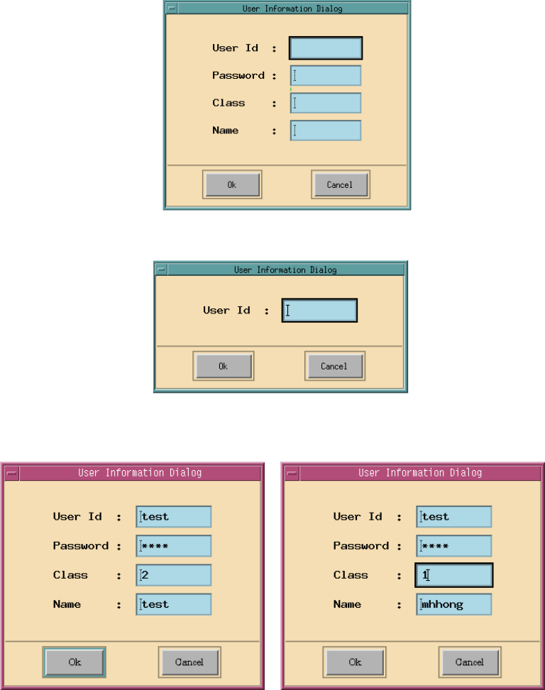
• ADD submenu : Super-user uses this menu to register a new user. The default grade of
user created newly is level 2. Figure 3.12 presents the input window in order to create or
add a new user in BSM.
• Delete submenu : This menu is used to delete the registered user. If you input a specific
user ID to the window such as Figure 3.13, you can delete it.
• Modify submenu : This menu is used to change the contents of the registered user. If
you select “Modify” menu, the input window is displayed and you can modify the user ID
in this window. If you input the modifying user Id and click “OK” button, the output
window is represented. This output window indicates the information of “User ID”,
“Password”, “Class” and “Name”. You can edit each fields and you can modify the user
information by pressing ”OK” button. The window of modifying the user information is
presented in Figure 3.14. Figure 3.14 represents the example of changing the user
grade of authorization for the command. That is, this figure presents changing the
authorization level of “test” user.
User’s Manual
PROPRIETARY & CONFIDENTIAL 3-10
Figure 3.12 User Add
Figure 3.13 User Delete
Figure 3.14 Modify a user
User’s Manual
PROPRIETARY & CONFIDENTIAL 3-11
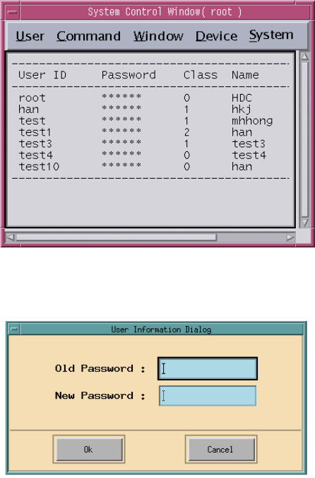
Figure 3.15 List up the user information
Figure 3.16 Change user’s password
• Display submenu : This button is used to output or display all the registered users.
Figure 3.15 presents the output window of the user information.
• Passwd submenu : This is used to modify the password of current log-on user in BSM.
In other words, this menu modifies root’s password. Figure 3.16 presents the window,
which changes the password of specific user.
• Close submenu : Termination of system function
3.1.3.3.3 Operations by Command menu
This menu is used to create or edit a CDD(Command Data Description) file and check the
contents of CDD file that currently registered in the system.
• File submenu : This menu is used to manipulate the CDD file. It consists of these
submenus: New, Open, Save, SaveAs, Print, Delete, and Quit
User’s Manual
PROPRIETARY & CONFIDENTIAL 3-12
• Check submenu :This menu is used to check all the CDD file and then displays its result
in the corresponding window.
3.1.3.3.4 Operations by Window menu
This menu is used to arrange several windows.
• Tiling submenu : It arranges and adjusts the unsettled windows.
3.1.3.3.5 “Device” menu
This menu is used to control the peripheral devices connected to the BSM workstation.
There are three submenus in this menu as follows:
• Printer submenu : This menu is set to the kind of printer, and decides the setting of the
printer mode, On/Off.
• Speaker submenu : This menu is set to audio device mode, On/Off.
• Modem submenu : Not implemented
User’s Manual
PROPRIETARY & CONFIDENTIAL 3-13
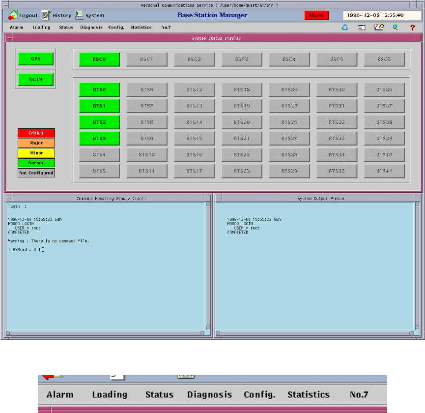
3.1.4 Command Buttons
BSM system provides dozens of commands for CDMA system. These buttons are
presented in Figure 3.17.
Figure 3.17 BSM Main Screen
Figure 3.18 Command Panel
3.1.4.1 Operation of Alarm Command
User’s Manual
PROPRIETARY & CONFIDENTIAL 3-14
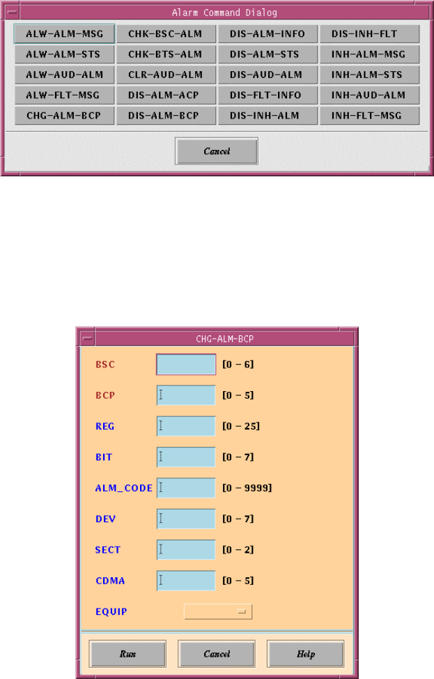
(1) If you select “Alarm” button in the Command Panel of Figure 3.18, “Alarm Command
Dialog” window is represented. In this window, if you select the command button to
process, BSM displays the window that you are able to input parameters for the
corresponding command.
Figure 3.19 Alarm Command Dialog
(2) If the window displays, which operators can input the related parameters to the system
for the corresponding command in Figure 3.19, you may enter the values of
parameters and then press “Run” button.
Figure 3.20 Parameter Input Window : Example of CHG-ALM-BCP
(3) In the command window, the corresponding message for the parsed command is
User’s Manual
PROPRIETARY & CONFIDENTIAL 3-15
represented and BSM executes it.
(4) If you need to help for the corresponding command, you can click “Help” button and
refer to help message.
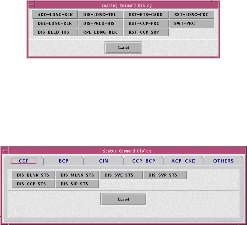
3.1.4.2 Operations by Loading Command
If you select “Loading” button in the Command Panel of Figure 3.18, “Loading Command
Dialog” window is represented.
Its function is same to that of the “Alarm” command.
Figure 3.21 Loading Command Dialog
3.1.4.3 Operation by Status Command
If you select “Status” button in the Command Panel of Figure 3.18, the Status Command
Dialog window is represented as follows.
Its function is same to that of the “Alarm” command.
Figure 3.22 Status Command Dialog - CCP
User’s Manual
PROPRIETARY & CONFIDENTIAL 3-16
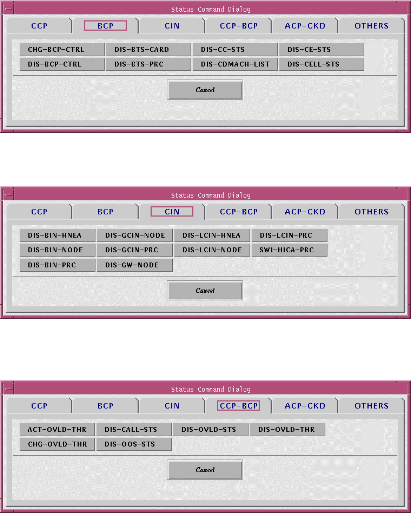
Figure 3.23 Status Command Dialog - BCP
Figure 3.24 Status Command Dialog – CIN
Figure 3.25 Status Command Dialog – CCP-BCP
User’s Manual
PROPRIETARY & CONFIDENTIAL 3-17
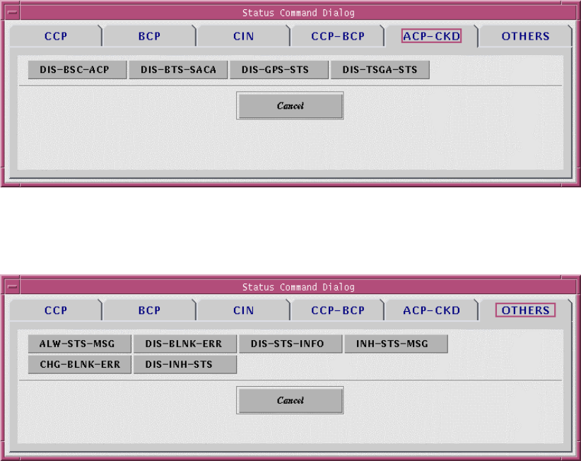
Figure 3.26 Status Command Dialog – ACP-CKD
Figure 3.27 Status Command Dialog – OTHERS
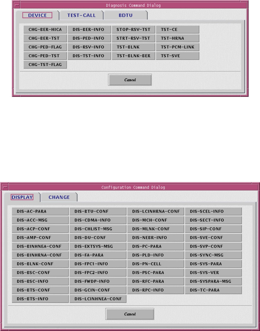
3.1.4.4 Operations to Diagnosis Command
If you select “Diagnosis” button in the Command Panel of Figure 3.18, the Diagnosis
Command Dialog displays as follows.
Its function is same to that of the “Alarm” command.
User’s Manual
PROPRIETARY & CONFIDENTIAL 3-18
Figure 3.28 Diagnosis Command Dialog
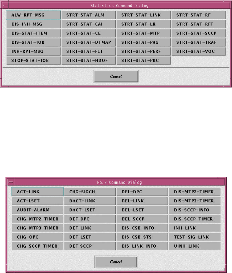
3.1.4.5 Operations by Configuration Command
If you select “Config” button in the Command Panel of Figure 3.18, the Configuration
Command Dialog is represented as follows.
Its function is same to that of the “Alarm” command.
Figure 3.29 Configuration Command Dialog
User’s Manual
PROPRIETARY & CONFIDENTIAL 3-19
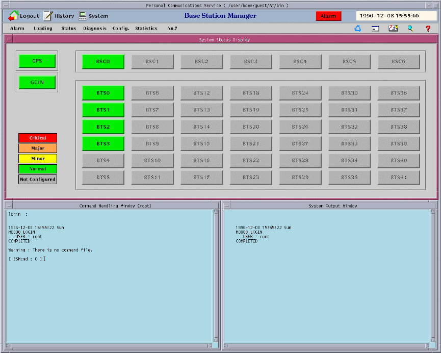
3.1.4.6 Operations by Statistics Command
If you select “Statistics” button in the Command Panel of Figure 3.18, the Statistics
Command Dialog is represented as follows.
Its function is same to that of the “Alarm” command.
Figure 3.30 Statistics Command Dialog
3.1.4.7 Operations by No.7 Command
If you select “No.7” button in the Command Panel of Figure 3.18, the No.7 Command
Dialog is represented as follows.
Its function is same to that of the “Alarm” command.
Figure 3.31 No.7 Command Dialog
User’s Manual
PROPRIETARY & CONFIDENTIAL 3-20
3.1.5 Service Button
There are five service buttons in the Service Panel of Figure 3.32. These buttons help to
the operators managing the systems efficiently or easily.
Figure 3.32 BSM Main Screen
3.1.5.1 Change the user grade of command
The function of this button in the Service Panel of Figure 3.33 is to output the command list
by user grade or authorization and change the grade or authorization of the specific
command. This function is used by the only super-user(root). There are three authorization
grades: Super-user, First class user who is able to verify and change the parameters of
User’s Manual
PROPRIETARY & CONFIDENTIAL 3-21
system, and Second class user who is able to use basic function and confirm the status of
system. Command list is arranged by alphabet order.
Figure 3.33 Service Panel – Change Command Class
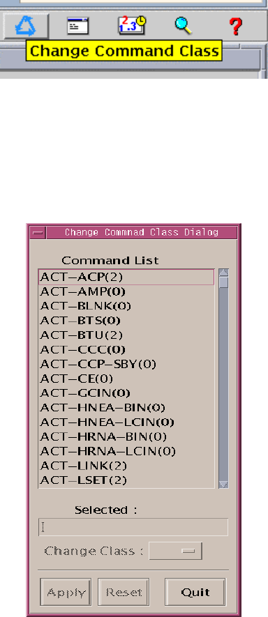
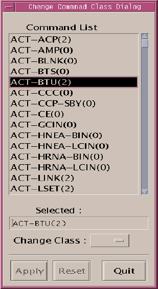
• Pressing the button in the Service Panel of Figure 3.33 displays the screen to change
the command class.
Figure 3.34. Change Command Class Window
• In the command list of the Change Command Class Window of Fig. 3.34, all the
commands are listed in alphabetical order and the number in the parentheses means
the class. Double click an item to change the class.
User’s Manual
PROPRIETARY & CONFIDENTIAL 3-22
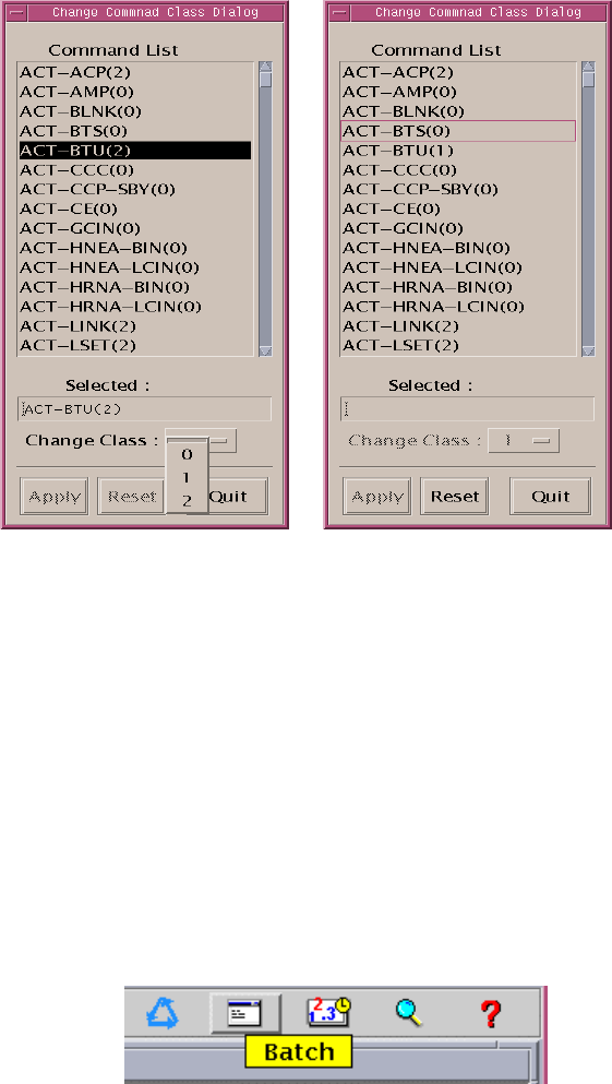
Figure 3.35 Double Click Command to Change Class
• Clicking the pop-down button of the Change Command Class Window shows as follows.
Click one of these classes and press Apply button, then the changed class is applied to
the command list.
User’s Manual
PROPRIETARY & CONFIDENTIAL 3-23
Figure 3.36. Change the Class of ACT-BDTU to Class 1
• If you want to turn it back to the original class, press Reset button.
• Pressing Quit button ends the function.
3.1.5.2 Batch
This service button in Figure 3.37 is able to write, edit, and execute the batch file. This file
is composed of a series of BSM commands.
Figure 3.37 Service Panel - Batch
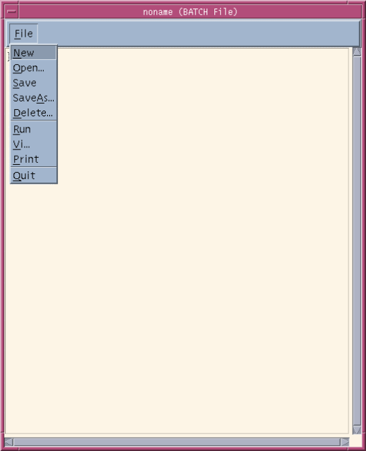
• If you press “Batch” button in the Service Panel, BSM displays such as Figure 3.38.
• The File menu in the Batch File Editor of Figure 3.38 has several commands as below:
a) New - New batch file.
User’s Manual
PROPRIETARY & CONFIDENTIAL 3-24
b) Open - Open and read an existing batch file.
c) Save - Save the batch file written by operator.
d) SaveAs - Save the batch file to another file name.
e) Delete - Delete the batch file.
f) Run - execute Batch in the editor window.
g) Vi - run Vi editor
h) Print - Print the contents of file.
i) Quit - Quit Batch File Editor.
Figure 3.38 Batch File Editor
Example of Batch file :
User’s Manual
PROPRIETARY & CONFIDENTIAL 3-25
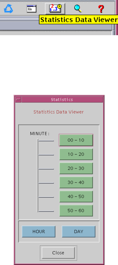
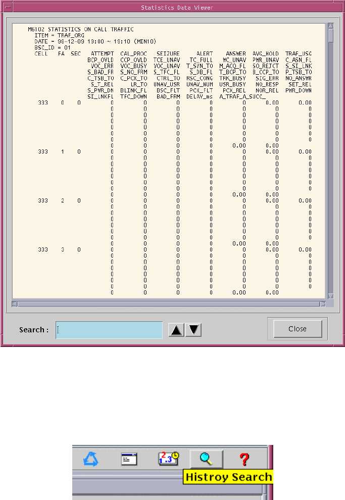
3.1.5.3 Statistics Data Viewer
Figure 3.39 Service Panel – Statistics Data Viewer
• If you press the button “Statistics Data Viewer” in Service Panel, you can see the
window such as Figure 3.40. The function of this window is that the binary statistic data
occured for 10 minute , 1 hour or 1 day is converted to the text type data.
Figure 3.40 Statistics Data Viewer
• For example, if you press “00-10” button in the window of the Figure 3.40, the statistic
text data for 10 minutes ( 00 - 10 minutes ) is displayed in the following window. Scroll
Bar is used for moving the screen or searching any words.
• Usage of the word searching function : If you enter the word that you want to search in
the “Search : “ Text Field and push the Arrow Button () (or enter the RETURN Key).
Then the screen moves the location of the word to the first location of word or string that
you want to search. It is possible to use the Down Arrow button or Return Key if you
User’s Manual
PROPRIETARY & CONFIDENTIAL 3-26
want another locations of the word, The Up Arrow Button is used for searching the word
to the upper field.
Figure 3.41 Statistics Data Viewer : 00-10
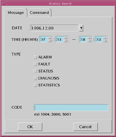
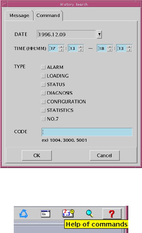
3.1.5.4 History Search
Figure 3.42 Service Panel – History Search
• The “History Search” of the Service Panel provides the fuction of “History search”,
shown in Figure 3.42. It is possible to search the types of date, time, kind, and code for
User’s Manual
PROPRIETARY & CONFIDENTIAL 3-27
command and message history in BSM.
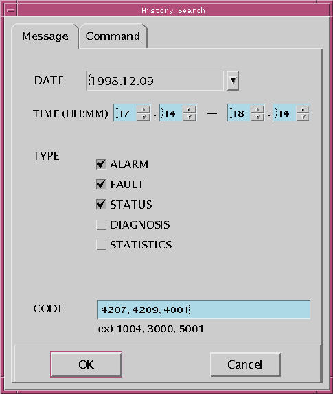
3.1.5.4.1 Search Message History
Figure 3.43 Search Message History
• Message History Search Initial Screen is shown in Figure 3.43. The default values for
DATE and TIME are current values for one hours. If You don’t set the TYPE and CODE,
all messages are displayed for the setting values.
• TYPE can be selected several items at one time. Also, CODE can be inputted several
values by using comma(,), Among messages of selected type, the messages related to
inputted CODE are displayed
• For example, in case Figure 3.44, messages related to CODE number 4207, 4209, and
4001 among alarm, fault, and status messages occured from 17:14 to 18:14 in
09/12/1998 would be searched and displayed.
User’s Manual
PROPRIETARY & CONFIDENTIAL 3-28
Figure 3.44 Example of Search Message History
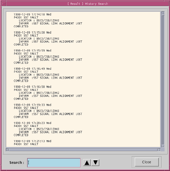
• If “OK” button is clicked, the window like Figure 3.45 would be poped up at center of
screen.
User’s Manual
PROPRIETARY & CONFIDENTIAL 3-29
Figure 3.45 Result of Search Message History
3.1.5.4.2 Search Command History
• “Command history search initial window” is showned in Figure 3.46. Operation can be
refferd to “message history search”.
User’s Manual
PROPRIETARY & CONFIDENTIAL 3-30
Figure 3.46 Search Command History
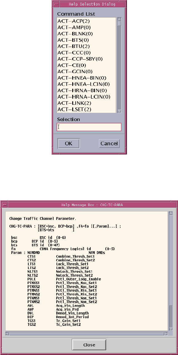
3.1.5.5 Help
Figure 3.47 Service Panel – Help of Commands
• Press “Help” in the Service Panel of Figure 3.47, and “Help Selection Dialog” window of
Figure 3.48 is represented.
User’s Manual
PROPRIETARY & CONFIDENTIAL 3-31
Figure 3.48 Help Selection Dialog
• Select one command in the command list and press “OK” button(or Double-click one
command), and the help message for the command appears:
Figure 3.49 Help Message
User’s Manual
PROPRIETARY & CONFIDENTIAL 3-32
3.1.6 Operations of “Alarm” window
Alarm window displays the fault status of each subsystem in the system. It uses several
colors to report the status of system to the operator efficiently and effectively in the window
with text message. So, you can understand easily in overall of system.
3.1.6.1 Types of Alarm Displays
The fault that operators take action rapidly must create the alarms. There are three types
of alarms as follows:
(1) Audible alarm – outputs the voice and sound alarms through the speaker.
(2) Visible alarm – outputs the colorful alarm display through the monitor.
(3) Alarm message – outputs the text alarm messages in the output window.
3.1.6.2 Grades of Alarms
(1) Normal alarm
This represents a normal status of subsystem and BSM displays this status with green
color.
(2) Critical alarm
This grade of alarm is critical to the system. So, this alarm is required to take
emergency actions for the fault status with no regard to the occurrence time of fault.
BSM displays these alarms with red color.
(3) Major alarm
This grade of alarm has an effect on services of system. It represents the fault status
or malfunction of main circuits. These faults are reported to operator immediately and
enable him to diagnose the functions of system or to recover the errors. The priority of
this alarm is not prior to that of critical alarm. So, this alarm effects on the
performance of the system directly or steadily (Orange).
(4) Minor alarm
This grade of alarm has a little effect on services of the system or subscribers. That is,
this alarm hardly effects on the functions of call processing. The priority of this alarm
User’s Manual
PROPRIETARY & CONFIDENTIAL 3-33
is lowest (Yellow).
(5) Not Configured / Not Equip
This grade of alarm is not equipped to devices or cards (Gray).
3.1.6.3 The method of alarm detection
If the system reports the alarms to the operator and BSM, BSM displays the alarm status
to the corresponding location in BSM using colors according to the grade of alarm.
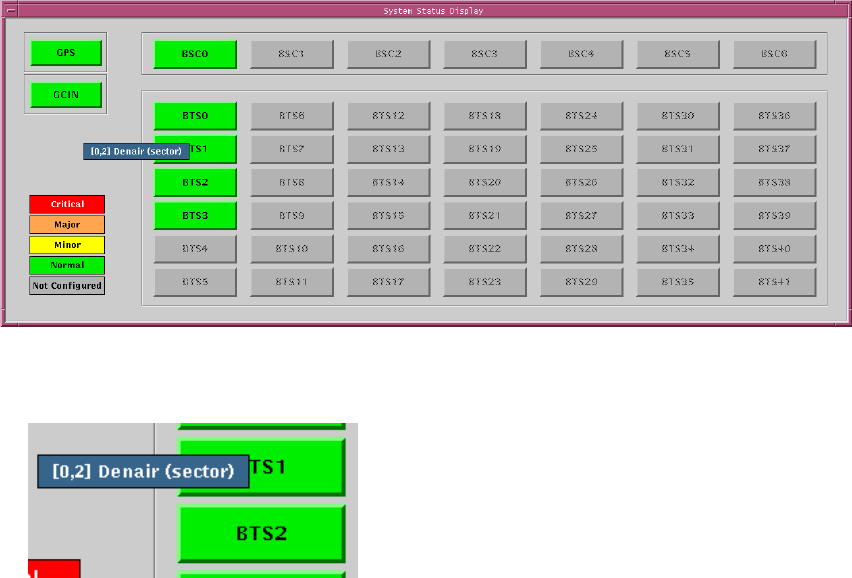
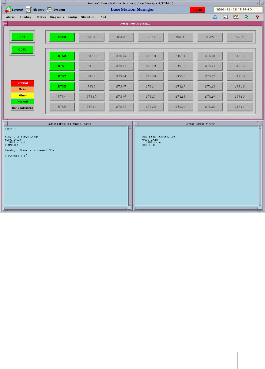
3.1.6.4 Main window of subsystems
Main window is composed of four parts: BSC, GCIN, GPS and BTS. If you want to know
the status of corresponding subsystems, you move the mouse to the button of
corresponding subsystem and click it.
Figure 3.50 Main window of subsystems
User’s Manual
PROPRIETARY & CONFIDENTIAL 3-34
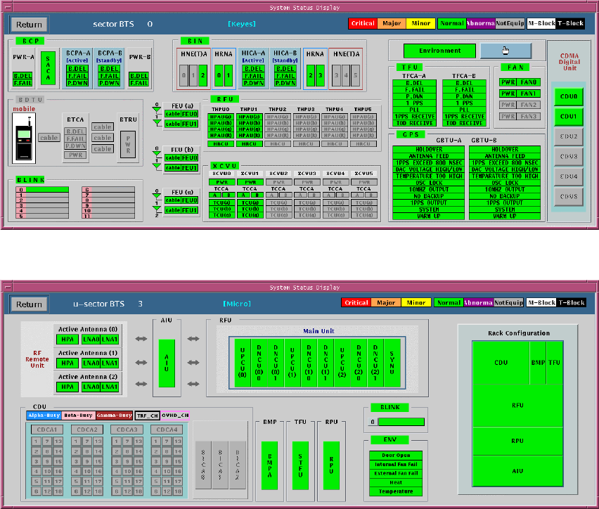
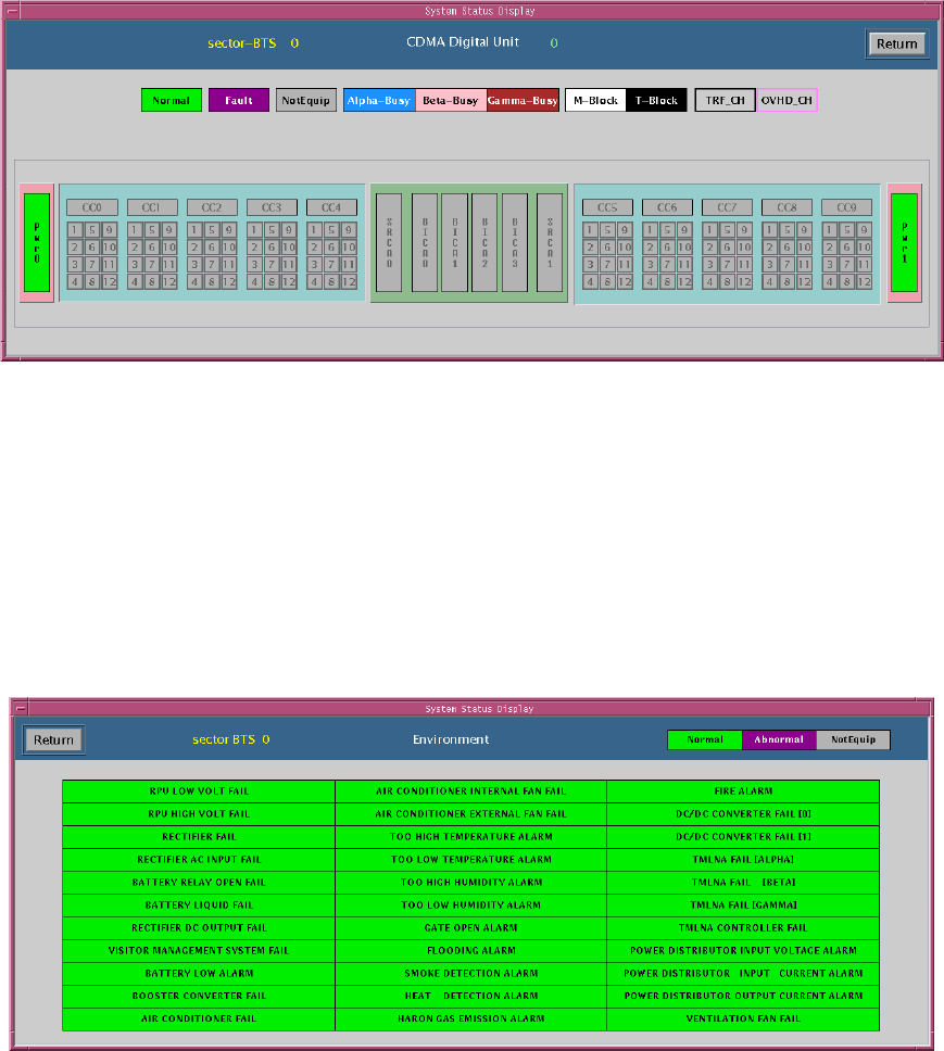
3.1.6.4.1 Main window of BTS
If you intend to know the status of BTS, you may click the button of corresponding BTS ID.
Then, the following window of Figure 3.51 and Figure 3.52 displays and represents all the
statuses of BTS in detail. The board equipped in the system displays green color. If one of
them produces alarms, BSM displays its status with red, orange, and yellow color
according to the grade of alarm.
You can move to the previous display window by pressing “Return” button or “Space bar”
key.
Figure 3.51 Main window of BTS
Figure 3.52 Main window of Micro-BTS
3.1.6.4.2 Main window of CDU
If you press a “CDU” button in the window of Figure 3.51, the window of Figure 3.53
User’s Manual
PROPRIETARY & CONFIDENTIAL 3-35
displays. If you press “Return’ key or “Space bar” key, you can be back to the previous
window.
Figure 3.53 The window of CDU
3.1.6.4.3 Main window of ENV
If you press a “Environment” button in the window of Figure 3.51, the window of Figure
3.54 displays. If you press “Return’ key or “Space bar” key, you can be back to the
previous window.
Figure 3.54 The window of BTS ENV
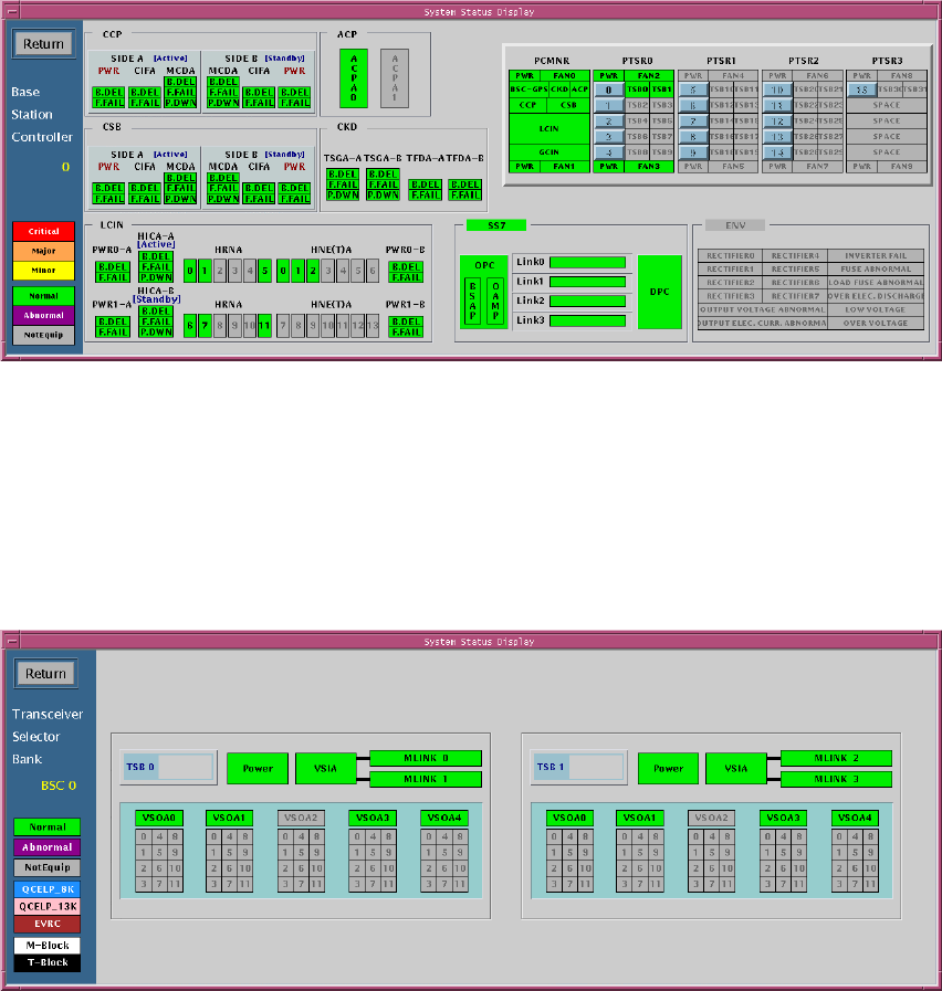
3.1.6.4.4 Main window of BSC
User’s Manual
PROPRIETARY & CONFIDENTIAL 3-36
Figure 3.55 The window of BSC
3.1.6.4.5 Main window of TSB
If you press a TSB button in Figure 3.55, the following window of Figure 3.56 is
represented.
Figure 3.56 The window of TSB
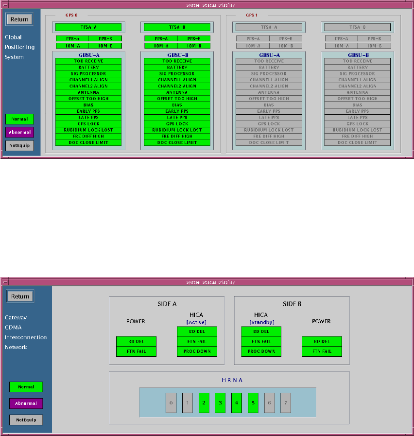
3.1.6.4.6 Main of GPS
When you press the “GPS” button of Figure 3.50, the following window of Figure 3.57 is
represented.
User’s Manual
PROPRIETARY & CONFIDENTIAL 3-37
Figure 3.57 The window of GPS
3.1.6.4.7 Main of GCIN
When you press the “GCIN” button of Figure 3.50, the following window of Figure 3.58 is
represented.
Figure 3.58 The window of GCIN
3.1.6.5 Command Handling Window
Command Handling window of Figure 3.59 outputs the contents of inputted command for
the text-typed command or the command using GUI. And, it displays its results.
User’s Manual
PROPRIETARY & CONFIDENTIAL 3-38
Figure 3.59 BSM Main Screen
3.1.6.5.1 Command Re-execution Method
This provides the simple method of executing the previously executed command. Re-
execution of the recently entered 20 commands is available.
(1) h Command
Entering h (or H) in the Command window and pressing Enter key displays the list of
recently entered 20 commands.
[ BSMcmd : 40 ] h

User’s Manual
PROPRIETARY & CONFIDENTIAL 3-39
21 DIS-ALM-STS:BSC=0;
22 DIS-ALM-STS:BSC=1;
23 DIS-ALM-STS:BSC=2;
24 DIS-ALM-STS:BSC=3;
25 DIS-ALM-STS:BSC=4;
26 DIS-ALM-STS:BSC=5;
27 DIS-ALM-STS:BSC=6;
28 DIS-ALM-STS:BSC=7;
29 DIS-ALM-STS:BSC=8;
30 DIS-ALM-STS:BSC=9;
31 DIS-ALM-STS:BSC=10;
32 DIS-ALM-STS:BSC=11;
33 DIS-ALM-STS:BTS=0;
34 DIS-ALM-STS:BTS=1;
35 DIS-ALM-STS:BTS=2;
36 DIS-ALM-STS:BTS=3;
37 DIS-ALM-STS:BTS=4;
38 DIS-ALM-STS:BTS=5;
39 DIS-ALM-STS:BTS=6;
40 h
[ BSMcmd : 41 ]
Table Error! No sequence specified.. Example of h Command Result
(2) Command Re-execution
1) ! + (Command Number)
2) ! + (Command Initial String)
3) !!
You can re-execute the previously entered command by the above 3 methods.
The next table follows the Example of h Command Result of Table 1.
35 DIS-ALM-STS:BTS=2;
36 DIS-ALM-STS:BTS=3;
37 DIS-ALM-STS:BTS=4;
38 DIS-ALM-STS:BTS=5;
39 DIS-ALM-STS:BTS=6;
40 H

User’s Manual
PROPRIETARY & CONFIDENTIAL 3-40
[ BSMcmd : 41 ] !35
Table Error! No sequence specified.. ! + Command Number

User’s Manual
PROPRIETARY & CONFIDENTIAL 3-41
35 DIS-ALM-STS:BTS=2;
36 DIS-ALM-STS:BTS=3;
37 DIS-ALM-STS:BTS=4;
38 DIS-ALM-STS:BTS=5;
39 DIS-ALM-STS:BTS=6;
40 H
[ BSMcmd : 41 ] DIS-ALM-STS:BTS=2;
Table Error! No sequence specified.. Result
• Input (in italic) as shown in the Table 2 is replaced by the command corresponding to
the number as in the Table 3. Pressing Enter key at this state executes the command
immediately. If you want to modify the command, edit with the mouse, Delete or
Backspace key and press Enter key.
35 DIS-ALM-STS:BTS=2;
36 DIS-ALM-STS:BTS=3;
37 DIS-ALM-STS:BTS=4;
38 DIS-ALM-STS:BTS=5;
39 DIS-ALM-STS:BTS=6;
40 h
[ BSMcmd : 41 ] !DI
Table Error! No sequence specified.. ! + String
35 DIS-ALM-STS:BTS=2;
36 DIS-ALM-STS:BTS=3;
37 DIS-ALM-STS:BTS=4;
38 DIS-ALM-STS:BTS=5;
39 DIS-ALM-STS:BTS=6;
40 H
[ BSMcmd : 41 ] DIS-ALM-STS:BTS=6;
Table Error! No sequence specified.. Result
• Input (in italic) as shown in the Table 4 is replaced by the latest command that begins

User’s Manual
PROPRIETARY & CONFIDENTIAL 3-42
with the string as in the Table 5. Pressing Enter key at this state executes the command
immediately. If you want to modify the command, edit with the mouse, Delete or
Backspace key and press Enter key.
35 DIS-ALM-STS:BTS=2;
36 DIS-ALM-STS:BTS=3;
37 DIS-ALM-STS:BTS=4;
38 DIS-ALM-STS:BTS=5;
39 DIS-ALM-STS:BTS=6;
40 h
[ BSMcmd : 41 ] DIS-ALM-STS:BSC=0;
1998-04-18 11:40:34 Fri
M1004 DISPLAY ALARM STATUS
CCP 0 NO ALARM STATUS
DISPLAY BCP ALARM COUNT
BCP_ID CRI MAJ MIN
[ BSMcmd : 42 ] !!
Table Error! No sequence specified.. !! Command
38 DIS-ALM-STS:BTS=5;
39 DIS-ALM-STS:BTS=6;
40 H
[ BSMcmd : 41 ] DIS-ALM-STS:BSC=0;
1998-04-18 11:40:34 Fri
M1004 DISPLAY ALARM STATUS
CCP 0 NO ALARM STATUS
DISPLAY BCP ALARM COUNT
BCP_ID CRI MAJ MIN
[ BSMcmd : 42 ] DIS-ALM-STS:BSC=0;
Table Error! No sequence specified.. Result
• Input (in italic) as shown in the Table 6 is replaced by the previously executed command
User’s Manual
PROPRIETARY & CONFIDENTIAL 3-43
as in the Table 7. Pressing Enter key at this state executes the command immediately. If
you want to modify the command, edit with the mouse, Delete or Backspace key and
press Enter key.
3.1.6.5.2 Help Command in the Command Handling Window
(1) (Command + ?)
• In command window, if you want to print the command help, you must input command
+ ? or command + ?+;.
[ BSMcmd : 1 ]
1998-07-02 09:37:34 Thu
• CHG-SECT-INFO HELP MESSAGE
• Change Sector Information.
CHG-SECT-INFO : {BSC=bsc, BCP=bcp}, SECT = sect {[Param] ;
{BTS=bts }
bsc BSC id (0-11)
bcp BCP id (0-31)
bts BTS id (0-383)
sect Sector id (ALPHA, BETA, GAMMA)
Param :
PILOT Pilot Offset
TXFA Tx Fine Adjust
TXCA Tx Coarse Adjust
RXFA Rx Fine Adjust
RXCA Rx Coarse Adjust
RTDTHR Common Round Trip Delay Thresh
CYCIDX Max Slot Cycle Index
PREV CAI Revision
PMREV CAI Minimum Revision
(2) ?XXX (? + string)
User’s Manual
PROPRIETARY & CONFIDENTIAL 3-44
• If you attatched ? at any string, you can see all commands involving the string.
[ BSMcmd : 1 ] ?SECT
1 CHG-SECT-INFO
2 DIS-SECT-INFO
[ BSMcmd : 2 ] ?CE
3 CHG-CE-CONF
4 CHG-CE-TYPE
5 CHG-SCEL-INFO
6 DIS-CE-STS
7 DIS-PN-CELL
8 DIS-SCEL-INFO
9 DIS-TCE-STS
10 STRT-STAT-CE
11 TST-CE
[ BSMcmd : 3 ] ?-CE-
12 CHG-CE-CONF
13 CHG-CE-TYPE
14 DIS-CE-STS
[ BSMcmd : 3 ] ?
1 ACT-LINK
2 ACT-LSET
3 ACT-OVLD-THR
4 ADD-LDNG-BLK
5 ADD-NEBR
6 ALW-ALM-MSG
. . .
248 TST-SVE
249 UINH-LINK
All commands are displayed.

User’s Manual
PROPRIETARY & CONFIDENTIAL 3-44
3.2 System Status Management
3.2.1 System Status Test
BSC system may always audit and monitor processor status, alarm status, channel and
link status whether the call is normal. If the status is abnormal or system has a certain
fault, BSC system may take an action and then maintain the active status of system.
3.2.1.1 Alarm Test
(1) Alarm Monitoring
1) If the BSC system is an abnormal status or makes a certain fault, system may be
alerting the alarms. So, it must maintain the audible or visible alarm status in order to
output and create an alarm.
2) If you inhibited the audible or visible alarm, you must be always aware of not
outputting those alarms when the system is an abnormal status or a fault.
3) In reporting alarms to the system, it outputs the content of alarm and it checks the
corresponding block automatically. So, it solves the problems to the reported alarm.
4) You input a command of outputting alarm status and verify whether the alarm is
occurred.
(2) Alarm Test
1) You enable the system to output the alarm messages created until now.
C1004 DIS-ALM-STS:[BSC=aa[,BCP=bb],BTS=cc];
aa : BSC ID
bb : BCP ID
cc : BTS ID
You make sure of the number of alarm messages in the corresponding block.
2) You are able to output the alarm message information and then confirm the

User’s Manual
PROPRIETARY & CONFIDENTIAL 3-45
corresponding alarms.
C1006 DIS-ALM-INFO:AN=aa;
aa : Alarm Number ( 0000 - 9999 )
In the output messages, you confirm the contents of alarms and check the
corresponding block. You have to take an action for the corresponding block in
order to solve the alarm status.
3) You verify to the inhibited output messages of a lot of alarm messages.
C1007 DIS-INH-ALM;
In this case, alarm code is not included in the output message.
4) You can change the alarm message generation mode. So, you can confirm to the
alarm messages occurred.
C1000 ALW-ALM-MSG:AN=aa;
aa : Alarm Code Number ( 0000 - 9999 )
You verify whether the alarm of inhibited output is not included on checking the
corresponding devices.
3.2.1.2 Fault Test
(1) Fault Audit
1) You always verify whether the fault is occurred according to the corresponding
system devices.
2) You must audit if the status of channel or link is blocked. So, you manage these
resources and then maintain them to the normal states for efficient call processing.
3) You check or audit the output alarm messages and verify if the corresponding

User’s Manual
PROPRIETARY & CONFIDENTIAL 3-46
devices are faults or abnormal.
(2) Fault Test for the listed items
1) You make sure whether the channel or link is blocked.
C3306 DIS-OOS-STS:BSC=aa,[BCP=bb,]DEV=cc,TYPE=dd;
aa : BSC ID
bb : BCP ID
cc : DEVICE TYPE ( SVE/MLNK/BLNK/TCE )
dd : Type ( MBLK/FBLK/TBLK )
2) You verify which fault message is inhibited.
C1008 DIS-INH-FLT;
The code of inhibiting message dose not report to the system.
3) When you want to print the inhibited fault message, you must release the messages
that cannot print or report to the system. Therefore, you have to allow the messages
to print.
C1002 ALW-FLT-MSG:FN=aa;
aa : Fault CodeNumber ( 0000 - 9999 )
3.2.1.3 Test for control of processor status
(1) The status audit of processor
1) You always verify whether the status of processors is normal.
2) You change the status of stand-by processor to active processor and verify if the
status of this processor is normal or abnormal.
3) If the status of processor is abnormal, you have to repair it rapidly.
4) For the processor is the main part of system, you have to maintain that one or more

User’s Manual
PROPRIETARY & CONFIDENTIAL 3-47
than processor is normal at least.
(2) Status test of processor
1) You verify if the status of CCP in the system is normal.
C3001 DIS-CCP-STS:[BSC=aa];
aa : BSC ID
If you don’t input the corresponding BSC ID, you can verify the statues of all
CCPs.
2) After you check and verify the status of processors, you switch over the status of
processor.
C2012 SWT-PRC:BSC=aa,PROC=CCP;
aa : BSC ID
You check the output message and verify if CCP is switched over in that message.
After the processor is switched over, you verify if its status is normal. If the system
does not have a standby processor, that is, it has only one processor, this command
is unable to be executed.
3) You verify the status of SIP in the system.
C3002 DIS-SIP-STS:BSC=aa;
aa : BSC ID
4) You check the status of SVP in the system.
C3003 DIS-SVP-STS:BSC=aa,[SIP=bb];
aa : BSC ID
bb : SIP ID
5) You verify the status of ACP in the system.

User’s Manual
PROPRIETARY & CONFIDENTIAL 3-48
C3401 DIS-BSC-ACP:[BSC=aa];
aa : BSC ID
6) You verify whether the processors of BTS are normal or abnormal.
C3101 DIS-BTS-PRC:BSC=aa,BCP=bb[,BTS=cc];
aa : BSC ID
bb : BCP ID
cc : BTS ID
7) You check whether the status of cards or boards in BTS is normal.
C3102 DIS-BTS-CARD:BSC=aa,BCP=bb[,BTS=cc],CARD=dd,MIC_CARD=ee;
aa : BSC ID
bb : BCP ID
cc : BTS ID
dd : SRC,TCC,TCU,TFC,BIC,GPS,AMP
ee : UP,DOWN,SYNU,BIC,STFU,RFRU
3.2.1.4 Status test for links and channels
(1) Status audit of links and channels
1) You verify if the statuses of links and channels are normal.
2) When the links of BTS is blocked, you note that the call is cut off.
3) When the links and channels are blocked, you use TST command to check the
states of them.
(2) Status test of links
1) You check whether the status of MSC-links is normal.
C3005 DIS-MLNK-STS:BSC=aa;
aa : BSC ID
2) You verify the status of BTS-links.

User’s Manual
PROPRIETARY & CONFIDENTIAL 3-49
C3007 DIS-BLNK-STS:[BSC=aa,BCP=bb];
[BTS=c]
aa : BSC ID
bb : BCP ID
cc : BTS ID
(3) Status test of channel
1) You check the status of vocoder.
C3004 DIS-SVE-STS:BSC=aa,SIP=bb[,SVP=cc];
aa : BSC ID
bb : SIP ID
cc : SVP ID
2) You verify the status of CE.
C3106 DIS-CE-STS:BSC=aa,BCP=bb[,BTS=cc],DU=dd;
aa : BSC ID
bb : BCP ID
cc : BTS ID
dd : DU ID
3.2.2 System Diagnosis
Diagnosis is the testing of resources that are closely related to call processing in operating
the system and its results is reported to the operators. If its results are abnormal, you
exclude this resource for the service of call process. If the resource of call process is
recoverable, you enable this resource to use the call services or to add the resource pool
of system immediately.
3.2.2.1 Diagnosis of vocoder
(1) Diagnostic method

User’s Manual
PROPRIETARY & CONFIDENTIAL 3-50
There are four diagnostic methods of vocoder: Polling, Code compare, physical test,
and algorithm test.
1) Polling
You use this method to initialize the SVE(DSP) which is requested to diagnose. As
a result of its response, you can verify or check the status of vocoder.
2) Code Compare
This diagnostic method uses the result that the system compares the original DSP
code in VSOA-A1’s DRAM to the code in DSP’s SRAM.
If the system starts to diagnose the vocoders, it compares the code of vocoder
requested which is the code of SRAM in the DSP module with that of normal
vocoder which is the code of DRAM in VSOA-A1.
If the result of comparing the codes is identical, system may initialize the
vocoder. If the system receives acknowledgment from vocoder, system regards
this vocoder as normal. Otherwise, system decides that the status of vocoder
itself is abnormal.
If the result of comparing the codes is not same, system loads the normal code
to the DSP’s SRAM and replaces the code of SRAM. Then, system compares
the codes again. If the result of comparing the codes also is not same, system
decides the SRAM-related error.
If the result of comparing as above is same, system sends the initialization
message to the vocoder again and then waits for its response.
If the system receives the response for the message of initialization, this
response represents that the abnormal vocoder changes to the normal one
again. Otherwise, system decides that the status of vocoder is abnormal.
3) Physical Test (Will be implemented)
It tests the state of the internal ALU and RAM of DSP.
4) Algorithm Test (Will be implemented)

User’s Manual
PROPRIETARY & CONFIDENTIAL 3-51
As it cmopares the the test tone in DSP with the encoding and decoding data using
the vocoder algorithm pointed by the operator, you can check the state of the
vocoder algorithm
5) All Test (Will be implemented)
It stops disgnosting in the step if it detecs the error diagnosting the vocoder as the
following sequence ; Code compare Physical test Algorithm test.

User’s Manual
PROPRIETARY & CONFIDENTIAL 3-52

User’s Manual
PROPRIETARY & CONFIDENTIAL 3-53
(2) Diagnostic Test
1) You can use the following command to verify the status of vocoder.
C3004 DIS-SVE-STS:BSC=a,SIP=b[,SVP=c];
a : BSC Id
b : SIP Id
c : SVP Id
2) Next, you test the vocoder using the following command.
C4017 TST-SVE:BSC=a,SIP=b[,SVP=c,SVE=d],LEVEL=e,ALGORITHM=f;
a : BSC Id
b : SIP Id
c : SVP Id
d : SVE Id
e : Test Level (POLL_TST/CODE_CMP/PHYSICAL_TST/ALGORITHM_TST/ALL)
f : Vocoder algorithm (QCELP_8K/QCELP_13K/EVRC)
(3) Inter-working with call processing
1) For vocoder is related with call processing directly, you can confirm enough to
diagnose the status of it.
2) In case of maintaining call, system decides on the normal state of vocoder. System
need not to diagnose, and reports the “BUSY” state to the operators.
3) If the vocoder is idle, system changes its state to test block (T_BLK) in order not to
use this resource not to set a call on diagnosing. And then, system enters to
diagnose.
4) After the diagnosis end up, system changes the state to idle and is able to use or
set a call service.
(4) Analysis for result of diagnosis
1) As a result of polling, vocoder sends VOC_OK/VOC_NOK to the system. If the
system is not able to receive the response normally, it decides on the abnormal
state of vocoder.

User’s Manual
PROPRIETARY & CONFIDENTIAL 3-54
2) The response of comparing to code of memory is composed to three messages:
VOC_OK, VOC_NOK, and RAM_ERROR. If the code is normal or system does not
receive the response, system decides that DSP chip is abnormal or makes a
problem. If the vocoders do not load normally to DSP chip, system decides that the
problem results from the error of SRAM or DSP chip.
3)(note 1) The vocoder reports the result of Physical test to VOC_OK|ALU_ERR|DSP_
RAM_ERR|RAM/ALU_ERR. ALU_ERR is the error in the arithmetic or register and
DSP_RAM_ERR is the error in RAM of DSP. RAM/ALU_ERR is the error
4) The vocoder reports the result of Algorithm test to VOC_OK|FREG_ERR|GAIN_
ERR|FREQ/GAIN_ERR. FREQ_ERR is the error for the frequency deviation
exceeding the reference value after the generated signal encoding and decoding.
GAIN_ERR is the error for the energy deviation exceeding the reference value after
the generated signal encoding and decoding. FREQ/GAIN_ERR is the error for
occurring both FREQ_ERR and GAIN_ERR.
5) The result of All test is reported all the case for 2) ~ 4).
6) If the error except the result of the seccsion 1) ~ 4), for example, NRSP_SVE|
VOC_BUSY|ALRDY_TEST|VOC_NEQ|NRSP_SVP, is reported, it is the result of
the abnormal diagnostic test. NRSP_SVE is the no responce of the vocoder and
VOC_BUSY is the case that the vocoder does not carry out the diagnostic order.
ALRDY_TEST is the case that the vocoder is executing other diagnostic command
and VOC_NEQ is the case that the vocoder is not equipped yet. NRSP_SVP is the
case that it can’t execute the order because of SVP no response.
3.2.2.2 Diagnosis of HRNA
(1) Diagnostic method
The diagnosis of HRNA’s Node is executed by HICA. There are two methods of
diagnoses – Polling and Self Test – but both methods are concurrently executed.
1) Polling
(note 1) 3) ~ 6) will be implemented ASAP.

User’s Manual
PROPRIETARY & CONFIDENTIAL 3-55
HICA sends polling messages to each of nodes which interfaces with processors.
As a response of several polling messages, HICA reports the status of nodes to
the system.
2) Self Test
Without having response to polling, HICA enters to the self test and system
verifies the minimum status of node. This test can be only used to setting to alarm
mask in case of not connecting to the processors. Self Test is the test which is a
loop-back test for the Tx and Rx of node.
(2) Diagnostic test
1) You can verify the status of HRNA using the following command.
C3204 DIS-GCIN-NODE;
C3205 DIS-LCIN-NODE:BSC=a;
C3206 DIS-BIN-NODE:{BSC=a,BCP=b};
{BTS=c}
a : BSC Id
b : BCP Id
c : BTS Id
2) You can use the following command to test and diagnose the node of HRNA.
C4016 TST-HRNA:DEV=a,{BSC=b,BCP=c,}HRNA=e,NODE=f;
{BTS=d,}
a : Test HRNA Type (GCIN/LCIN/BIN)
b : BSC Id
c : BCP Id
d : BTS Id
e : HRNA Id
f : HRNA NODE
(3) Analysis for the result of diagnosis
1) For the diagnosis of node is composed of one network unlike another test, this test
is impossible to test, after excluding the call services.
2) The diagnostic result of node represents OK or NOK. This result is meaningful for

User’s Manual
PROPRIETARY & CONFIDENTIAL 3-56
the only node that connects to the corresponding device, because this is capable of
self-test.
3.2.2.3 Diagnosis of BTS-link
(1) Diagnostic method
The diagnosis of B-link is executed by HICA. There are three type of tests : node test,
local loop-back test and remote loop-back test. This test is able to execute all tests
concurrently at once and you can verify the overall status of B-link by executing
concurrently.
1) Test method of node
This is a loop-back test for the node of HNTA.
2) Method of local loop-back test
You enable this loop-back test in the T1 FRAMER of HNTA which controls to the
mechanical links to check the data returned from HICA.
3) Method of remote loop-back test
This is executed by HICA, which is a part of LCIN and exchanges messages or
sends/receives the data. First, HICA connects to the Rx and Tx of HNTA’s T1
FRAMER in peer BIN and then starts to the loop-back mode test. After diagnosing,
HICA changes diagnostic mode to the original test mode.
(2) Diagnostic test
1) You use the following command to verify the status of BTS-link.
C3007 DIS-BLNK-STS:{BSC=a,BCP=b};
{BTS=c}
a : BSC Id
b : BCP Id
c : BTS Id

User’s Manual
PROPRIETARY & CONFIDENTIAL 3-57
2) You test for the BTS-links using the following command.
C4013 TST-BLNK:{BSC=b,BCP=c,}LINK=c,LEVEL=d,CNT=e,TERM=f;
{BTS=g}
a : BSC Id
b : BCP Id
c : Link Id
d : Test Level
(NODE_TST : BIN, LCIN HNTA Node Test)
(LOC_LOOP : BIN HICA <--> BIN HNTA, LCIN HICA <--> LCIN HNTA)
(RMT_LOOP : LCIN HICA <--> BIN HNTA)
e : TEST COUNT (Number of Test : if LEVEL is set to NODE_TST/LOC_LOOP, executes)
f : TEST Time(Minute : in case of level being a RMT_LOOP)
g : BTS Id
(3) Interworking of call processing
1) If the diagnosis of BTS-link is executed, all the signals lose themselves.
2) Before diagnosing, you consider sufficiently a possibility that several calls
multiplexed connect to the BTS-links.
3) Once the diagnostic command is executed, HICA notifies the T_BLOCK State of
BTS links to both BCP and CCP in order to inhibit them from transmitting all of
control signals. HICA continues to audit if the B-link is used for setting several calls.
As soon as the B-link is fully idle, HICA enters to diagnose the B-links.
4) After finishing the diagnosis, HICA releases T_BLOCK of BTS-links and then is
about to normal status of BTS-link.
5) When the system is normal and two or more than BTS-links are operating or useful
for call services at least, system only diagnoses them normally.
6) If the system uses only one BTS-link for call services and the system diagnoses this
link, it results in canceling diagnosis. On behalf of this test, HICA diagnoses one
hundred times of polling test for the corresponding link.
(4) Analysis for the diagnostic result
1) System counts the number of successful tests – HNTA Node’s test and Local loop-
back test.

User’s Manual
PROPRIETARY & CONFIDENTIAL 3-58
2) The results of remote loop back test represent the number of sending test packets,
successful packets and time-out packets during the test. Also, they represent the
number of packet loss returned. Additionally, HICA verifies bit error (Frame
alignment signal error), slip error and bipolar error. Parts of these messages can be
reported in executing the loop-back test actually or finishing the test.
3.2.2.4 Diagnosis of BTS’s Channel Element
(1) Diagnostic method
There is a polling test for diagnosis of channel element in BTS.
(2) Diagnostic test
1) You can verify the status of channel element in BTS using the following command.
C3106 DIS-CE-STS:{BSC=a,BCP=b}, DU=d;
{BTS=c}
a : BSC Id
b : BCP Id
c : BTS Id
d : Digital Unit Id
2) You can use the following command to test the status of channel element in BTS.
C4015 TST-CE:{BSC=a,BCP=b,}DUID=d,CDCA=e,SUBNODE=f,LEVEL=g,CNT=h;
{BTS=c}
a : BSC Id
b : BCP Id
c : BTS Id
d : Digital Unit Id
e : Channel Card Id
f : Subnode Id
g : Test Level
h : Polling Count
(3) Analysis for the diagnostic results

User’s Manual
PROPRIETARY & CONFIDENTIAL 3-59
The number of response for polling is reported to the system.
3.2.2.5 Others
(1) Reserved diagnosis
Reserved diagnosis is a function of MMC + Timer. That is, for MMC is executed
immediately, to diagnose on the busy hour itself is overloaded to the system. Therefore,
diagnosis is in middle of night. So, all the MMC commands are able to reserve. For the
information of reserved diagnosis is stored to PLD, system can get reserved diagnostic
information regardless of power on/off. Reserved diagnosis is executed according to
the information of PLD.
(2) Periodic Diagnosis
Periodic diagnosis is a function of MMC + Periodic Timer. That is, this is executed on
given time every day. This corresponds to B-link, CE, and SVE. For all information are
stored to the PLD, system can get the periodic diagnostic information from PLD
regardless of power on/off. The functions of periodic diagnosis are as follows:
allowance or disallowance for periodic test and change of test time.
(3) Automatic diagnosis
If the operator allows for this diagnosis by corresponding devices (BLNK or SVE), this
diagnosis always happens automatically regardless of operator’s will. Automatic
diagnosis is the audit on all the devices in the status management block – CSHX and
BSHX. When the status is changed from normal to abnormal or from abnormal to
normal, this diagnosis is executed immediately. If the devices are recoverable by
diagnosis, system repairs and recovers them automatically.

User’s Manual
PROPRIETARY & CONFIDENTIAL 3-60
3.2.3 Statistics
3.2.3.1 Overview
System can gather the statistic data according to the operator’s request or period and
reports them to the system. Therefore, the main goal of measurement and statistics is to
use the statistic data to re-design the system in the future or to set or install the system
based on these data. There are four grades or modules of measurement and statistics:
collection of raw data, data manipulation, storing to the data, and transmitting.
3.2.3.2 Configuration and Operation
(1) Operation
1) This operation starts to the collection of data by the command of the statistics start
command of BSM. It collects the data every 10 minutes and then reports to the
BSM. If it receives the start measurement from BSM, it orders the call processing
block to start the library calls. After it also receives the request for the measurement
or response from the other processors, it sends the response signal to the BSM.
BSM receives the data from call processing blocks through the libraries of CMMX
and BMMX. CCOX is a block of call processing and it enables CMMX to fetch the
data from the corresponding library buffer whenever producing events.
2) The start-up flow of measurement and statistics is as follows:
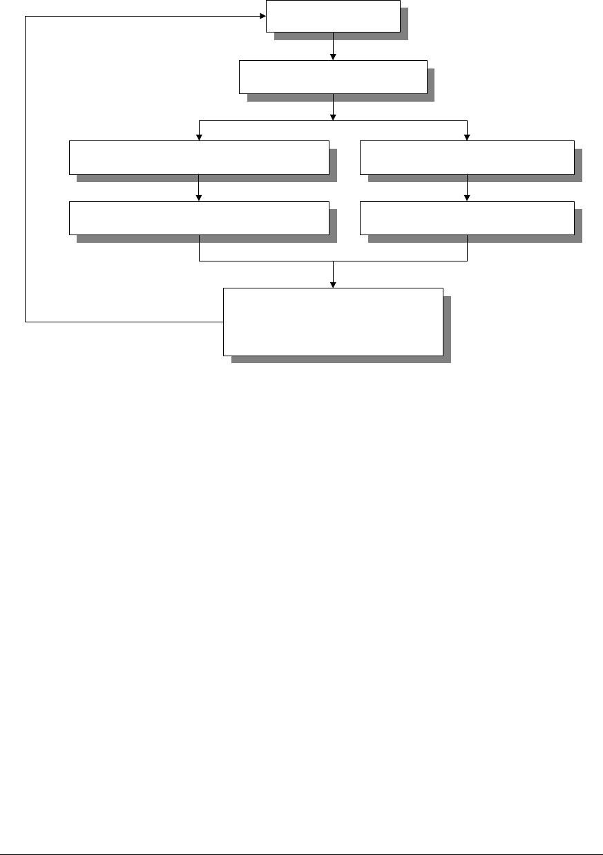
User’s Manual
PROPRIETARY & CONFIDENTIAL 3-61
BSM requests for the
measurements
Request for the timers of BSM itself
Send the request for data to the other processors Read the values of libraries.
After gathering the data and processing them,
store to the buffer After fetching the value of library and
processing it, store to the buffer.
After storing the data to the buffer, child
process reports the result of
measurement when BSM requests for
reporting the data.
Figure 3.61 Start-up flow of measurement and statistics
(2) Configuration of measurement and statistics
1) Statistics of Traffics
2) Statistics of Hand-offs
3) Statistics of Channel elements
4) Statistics of Vocoders
5) Statistics of Processors
6) Statistics of Performances
7) Statistics of CAI
8) Statistics of RFs
9) Statistics of BTS-links
10) Statistics of Faults
11) Statistics of Alarms

User’s Manual
PROPRIETARY & CONFIDENTIAL 3-62
12) Statistics of Paging
13) Statistics of RF’s performance in BTS.
14) Statistics of Location registrations
15) Statistics of No.7
3.2.3.3 Test for measurement and statistics
(1) Resevation for statistics data.
1) You use the following command to cancel the reservation for the data of statistics.
M6201 STOP-STAT-JOB:BSC=aa,JOB=bb,MPRD=cc;
aa : BSC ID
bb : JOB Number
cc : Measurement Periodic Time
2) If you entered the command, you can see the follows;
- In case of Success
M6201 STOP STATISTICS JOBS
ACCEPTED
RESULT = OK
COMPLETED
- In case of Failure
M6201 STOP STATISTICS JOBS
NOT ACCEPTED
RESULT = NOK
REASON = DATABASE NOT OPEN – cannot open the Database file
or INPUT ERROR – input error
or JOBS NOT FOUND – no report job reserved
or MPRD NOT FOUND – no Measurement Period inputted
or JOB_ID ERROR – JOB ID error
or MATCHING JOB NOT FOUND – no report JOB respond to input value
COMPLETED

User’s Manual
PROPRIETARY & CONFIDENTIAL 3-63
3) You use the following command to cancel the reservation for the data of statistics
M6001 DIS-STAT-JOB:bsc=bsc;
bsc : BSC ID
4) If you entered the command, you can see the follows;
- In case of Success
M6001 DISPLAY STATISTICS JOBS
BSC = bsc_id
SUB_ID JOB_NO STAT_ITEM START_TIME MPRD MTIM ITER
aa bb cc dd ee ff gg
...
RESULT = OK
COMPLETED
aa : SUB ID
bb : JOB Registration Number
cc : JOB Statistics Item
dd : Measurement Start Time
ee : Measurement Period
ff : Measurement Times
gg : Execution Times
- In case of Failure
M6001 DISPLAY STATISTICS JOBS
NOT ACCEPTED
RESULT = NOK
REASON = Fail Reasons*
COMPLETED
REASON = BSC NOT EQUIPPED – The entered BSC is not equipped.
or NO JOBS PLANNED – There is not reserved ststistics JOB.
or BSC_ID NOT ENTERED – Input Error for not entered BSC.
(2) Statistics of traffic
There are three types of the measurement and statistics of traffic according to
origination call, termination call, and both of all.
1) You use the following command to start up the traffic command.
C6102 STRT-STAT-TRAF:[BSC=a,[BCP=b,]]ITEM=c,MPRD=d,MTIM=e;
a : BSC ID (0 ~ 6)
b : BCP ID (0 ~ 5)
c : Statistics of Traffic ITEM (ORG|TER|ALL)
d : Measurement Periodical Time (MIN10|HALF|HOUR)

User’s Manual
PROPRIETARY & CONFIDENTIAL 3-64
e: Measurement Times (1 ~ 50)
System displays the “ACCEPTED” message.
• Gathering the data of statistics starts the absolute time on 10, 20, 30, 40, 50,
and 00 .
2) As soon as the operators request statistics, the data of statistics are accumulated.
Whenever the given periodic time (relative time 10, 30 and 60 minutes) is returned,
these data displays the following message within 10 minutes every hour.
M6102 STATISTICS ON CALL TRAFFIC
ITEM = TRAF_ORG
DATE = YY-MM-DD HH:MM ~ HH:MM
BSC_ID = aa
BTS FA SEC ATTEMPT CAL_PROC SEIZURE ALERT ANSWER AVG_HOLD TRAF_USG
BCP_OVLD CCP_OVLD TCE_UNAV TC_FULL WC_UNAV PWR_UNAV C_ASN_FL
VOC_ERR VOC_BUSY VOC_UNAV T_SYN_TO M_ACQ_FL SO_REJCT S_SI_LNK
S_BAD_FR S_NO_FRM S_TFC_FL S_DB_FL T_BCP_TO B_CCP_TO P_TSB_TO
C_TSB_TO C_PCX_TO CTRL_TO RSC_CONG TRK_BUSY SIG_ERR NO_ANSWR
S_T_REL LR_TO UNAV_USR UNAV_NUM USR_BUSY NO_RESP REL_CALL
S_PWR_DN BLINK_FL BSC_FLT PCX_FLT PCX_REL REL_TRAF PWR_DOWN
SI_LNKFL TFC_DOWN BAD_FRM DELAY_ms A_TRAF_% A_SUCC_%
bb c d x x x x x x x
x x x x x x x
x x x x x x x
x x x x x x x
x x x x x x x
x x x x x x x
x x x x x x x
x x x x
...
RESULT = OK
COMPLETED
M6102 STATISTICS ON CALL TRAFFIC
ITEM = TRAF_TER
DATE = YY-MM-DD HH:MM ~ HH:MM
BSC_ID = aa
BTS FA SEC ATTEMPT CAL_PROC SEIZURE ALERT ANSWER AVG_HOLD TRAF_USG
BCP_OVLD CCP_OVLD TCE_UNAV TC_FULL WC_UNAV PWR_UNAV C_ASN_FL
VOC_ERR VOC_BUSY VOC_UNAV T_SYN_TO M_ACQ_FL SO_REJCT S_SI_LNK

User’s Manual
PROPRIETARY & CONFIDENTIAL 3-65
S_BAD_FR S_NO_FRM S_TFC_FL S_DB_FL T_BCP_TO B_CCP_TO P_TSB_TO
C_TSB_TO C_PCX_TO CTRL_TO RSC_CONG TRK_BUSY SIG_ERR NO_ANSWR
S_PWR_DN BLINK_FL BSC_FLT PCX_FLT PCX_REL REL_TRAF PWR_DOWN
SI_LNKFL TFC_DOWN BAD_FRM DELAY_ms A_TRAF_% A_SUCC_%
bb c d x x x x x x x
x x x x x x x
x x x x x x x
x x x x x x x
x x x x x x x
x x x x x x x
x x x x
...
RESULT = OK
COMPLETED
aa : BSC ID
bb : BCP ID
c : FA ID
d : SECTOR ID
3) Analysis on the parameters of output message
The following parameters of statistics of traffic are related with origination calls.
Items Contents
ATTEMPT The number of attempting the originated calls using access channel
in MS.
Ÿ On receiving the message of Msg_Mob_Orig_Bc, this parameter
is counted
SEIZURE The number of successful link between mobile station and vocoder
Ÿ On receiving the message of Msg_Conect_sc, this parameter is
counted.
CAL_PROC The number of processing normal origination call in PCX
Ÿ When mobile station is requested to the origination call set-up to
PCX and receives the ACK, this parameter is counted.
ALERT The number of ring transmitted for the response of terminated call.
Ÿ When the message of Alert is received, this parameter is
counted.
ANSWER The number of normal call for the response of termination call

User’s Manual
PROPRIETARY & CONFIDENTIAL 3-66
TRAF_USG The rate of possessing channel of origination call (The count form of
certification : In case of the statistics of hourly time, the result is the
following. (ATT_HOLD*ATTEMPT)/3600)
AVG_HOLD he total possession time of channel
NORM_REL On maintaining a call, this parameter represents to being released by
the part of origination (Release a call of M/M or M/L calls from the
origination)
PCX_REL On maintaining a call, this parameter represents to being released by
the part of termination (Release a call of M/M or M/L calls from the
part of MS or Land)
PWR_DOWN The number of released calls by the power down of MS in normal
calls
BAD_FRM The number of released call by the data burst error due to the bad
radio environment in a call.
SI_LNKFL The number of cut-off calls due to the SI link fail in a call
TFC_DOWN The number of cut-off calls by TFC down during a call
SET_REL The number of released calls by the user of origination part before
answering for a call during the call set-up (The number of canceling
calls)
P_TSB_TO The number of released calls for not arriving to the control message
in time from MS during a call
M_ACQ_FL In case of TCE failing to obtain the set-up data of communication
channels from mobile station, a call is released
T_SYNC_TO In setting up TC link between TCE and TSB, this parameter
represents that Time Sync message does not arrive in the vocoder.
T_BCP_TO When the control signal of the origination call between TCE and BCP
is not arrived in vocoder on time, this parameter is counted for the
number of abnormal released call.
B_CCP_TO When the control signal of the origination call between BCP and
CCP is not arrived in vocoder on time, this parameter is counted for
the number of abnormal released call.
SO_REJCT Release the call for not processing the service option of MS.
VOC_ERR The fail of origination call for the error of vocoder initialization.

User’s Manual
PROPRIETARY & CONFIDENTIAL 3-67
TCE_UNAV If the resources of TCE are not able to assign them to the call or they
remain the reserved channels for hand-offs on receiving the
message of MobOrg, this parameter is used.
WC_UNAV The number of the failure of origination call which is unable to assign
Walsh Code channel for TC. That is, this is a bad channel of CDMA.
PWR_UNAV If there is no TC total power assigned for BTS, which is overloaded
to the BTS, this parameter is counted.
S_SI_LNK The number of released call for SI_LINK_FAIL on setting up a call
S_BAD_FR In case of producing a lot of bad data or losing much voice data for
producing a lot of bad data or voice data loss by the bad
environment of radio, this parameter is used to count for the number
of released calls.
DB_SL_FL The failure of origination call due to “DB Selection Fail” on a call
setup.
S_NO_FRM The number of released calls due to “NO FRAME” on a call setup
S_TFC_FL The failure of origination call due to “TFC Down” on a call setup.
VOC_UNAV If the system cannot assign the available resources to the call, this
parameter is used on receiving the normal originated call setup
messages from BCP.
BCP_OVLD The failure of the originated call due to being overloaded on the
processor of BCP
CCP_OVLD The failure of originated call due to being overloaded on the
processor of CCP.
C_TSB_TO After the CCP sends the indication message of setting up TC link to
TSB, if the CCP does not receive any response messages from TSB,
this parameter is used.
BSC_FLT The failure of originated call due to the other faults of BSC.
C_PCX_TO This parameter is used not to receive the message of making
progress the call for the request of call setup from the PCX within 5
seconds. Also, it is used not to receive the messages of terminated
ring from PCX within 20 seconds.
NO_ANSWR This parameter indicates that the “Connect” message is not arrived
in vocoder in one minute, after receiving the “Alert” message.

User’s Manual
PROPRIETARY & CONFIDENTIAL 3-68
BLINK_FL This parameter indicates that the call setup fails due to being
overloaded on CCP-BCP link, B-link and switching over the link.
USR_BUSY This parameter indicates the busy state of subscriber of terminated
call.
NO_RESP The number of released calls for the no response of first and second
paging on the part of termination.
LR_TO The number of released calls because the response of VLR or HLR
is not arrived in time on setting up a originated call.
UNAV_USR The number of released calls because the originated subscribers has
no authorization on setting up a originated call(No registration or the
inhibition of originated call)
UNAV_NUM The number of released calls because the terminated call is not able
to connect to the termination as a result of translating the number of
termination on a call setup.
RSC_CONG The number of released calls due to being overloaded on the switch
of PCX on a originated call setup
TRK_BUSY The number of released calls due to being lack of the trunks of PCX
in setting up a originated call.
SIG_ERR The number of released call due to being a signaling error of R2 or
No7 in setting up a originated call.
PCX_FLT This parameter is indicates the failure of originated call due to the
other faults of PCX. After CCP sends the message of “setup_cx” to
PCX, CCP receives the message of “Connection refused” due to no
registration, alarm, or failure of DB.
DELAY_ms The average delay time from call attempt to service
A_TRAF_% Call originated traffic rate
A_SUCC_% Call originated success rate
These parameters are related to the statistics of termination call’s traffic.
Items Contents
ATTEMPT This parameter indicates MS uses the access channel to attempt the
terminated call. It is counted on responding to paging.
SEIZURE The number of setting TC link up between MS and vocoder

User’s Manual
PROPRIETARY & CONFIDENTIAL 3-69
CAL_PROC The number of the normal terminated call on PCX.
ALERT The number of transmitting to RBT of the subscriber of termination.
ANSWER The number of responding the calls from the terminated subscribers.
TRAF_USG The rate of the channel possession of the terminated calls
AVG_HOLD The interval time(second) of the channel possession of the
terminated calls.
NORM_REL In case of releasing a call from termination on it.
PCX_REL In case of releasing a call from origination on it.
PWR_DOWN The number of calls released by the power down of MS in the normal
call.
BAD_FRM The number of released call when detecting on the bad frame in the
TSB on a call.
SI_LNKFL The number of cut-off calls due to the error of “SI Link Fail” on a call
TFC_DOWN The number of cut-off calls by the error of “TFC Down” in a call.
P_TSB_TO If the control message is not arrived in time from MS on setting up a
call, this parameter is used.
M_ACQ_FL When MS sends the message of setting the traffic channel to TCE, in
case of not obtaining the TCE, the call is canceled.
T_SYNC_TO When the TC link between TCE and TSB is set up, this parameter
indicates that “Time Sync Message” is not arrived in time.
T_BCP_TO The number of calls released in the terminated call setup for the
control messages between TCE and BCP is not arrived on time
B_CCP_TO The number of calls released in the terminated call setup for the
control messages between BCP and CCP is not arrived on time
SO_REJCT The number of calls released due to being unable to process the
service options of MS.
VOC_ERR The number of failures for the terminated calls due to the failure of
vocoder initialization in setting up a call.
TCE_UNAV In case of no resources of TCE on receiving the message of “Page
response” or in case of remaining the only reserved channel for
handoff, this parameter indicates not to assign the resources for a
call.

User’s Manual
PROPRIETARY & CONFIDENTIAL 3-70
WC_UNAV The failure of terminated call due to being unable to assign Walsh
code channel
PWR_UNAV The failure of terminated call for lack of assigned power of BTS
S_SI_LNK The number of calls released because of SI_LINK_FAIL on a call
setup
S_BAD_FR In case of producing a lot of bad data or losing much voice data by
the bad environment of radio, this parameter is used to count for the
number of calls released or the number of SI link failures in a call
setup.
DB_SL_FL The failure of originated call due to the failure of DB selection in a call
setup
S_NO_FRM The number of calls released due to “No Frame” in setting a call up.
S_TFC_FL The failure of originated call due to “TFC down” in setting a call up
VOC_UNAV The failure of terminated call for lack of the resources of vocoder
BCP_OVLD The failure of terminated call due to overloaded on BCP.
CCP_OVLD The failure of terminated call due to overloaded on CCP.
C_TSB_TO After the CCP sends the indication message of setting up TC link to
TSB, if the CCP does not receive any response messages from TSB,
this parameter is used.
BSC_FLT The failure of originated call due to the other faults of BSC
C_PCX_TO If the message of making progress a call, Call Conf, is not received
from PCX for the response of paging within 5 seconds, this
parameter is used.
NO_ANSWR The number of failures due to no response from terminated
subscribers in the terminated call setup.
BLINK_FL The deadlock or cut-off of B-links
RSC_CONG Failure of terminated call for lack of the resources of switches and
trunks
SIG_ERR The number of calls released due to the error of R2 and No.7 in
setting up the terminated call
PCX_FLT Failure of Originated call due to the other faults of PCX
DELAY_ms The average delay time from call attempt to service
A_TRAF_% Call originated traffic rate

User’s Manual
PROPRIETARY & CONFIDENTIAL 3-71
A_SUCC_% Call originated success rate
(3) Statistics of Hand-off
There are three types of measurement and statistics : softer, soft, and Hard hand-off.
Hard hand-off has three types : Intra-HHO, Inter-HHO, and Intra-Cell.
1) You use the following command to start the statistics of hand-off.
C6103 STRT-STAT-HDOF:[BSC=a,[BCP=b,]]ITEM=c,MPRD=d,MTIM=e;
a : BSC Id (0 ~ 6)
b : BCP Id (0 ~ 5)
c : Statistic item of Handoff (HHO|SHO|RHO|ALL)
d : Measurement Period (MIN10|HALF|HOUR)
e : Measurement Times (1 ~ 50)
System displays the “ACCEPTED” message.
Ÿ Gathering the data of statistics starts the absolute time on 10, 20, 30, 40, 50,
and 00 .
2) As soon as the operators request statistics, the data of statistics are accumulated.
Whenever the given periodic time (relative time 10, 30 and 60 minutes) is returned,
these data displays the following message within 10 minutes every hour.
- In case of Softer Handoff
M6103 STATISTICS ON HANDOFF
ITEM = HO_SOFTER
DATE = YY-MM-DD HH:MM ~ HH:MM
BSC_ID = aa
BTS_ID FR_SEC TO_SEC ATT_ADD ATT_DRP SUC_ADD SUC_DRP
CC_UNAV SYS_FLT HCM_FAIL CALL_DRP A_SUCC_%
bb c c x x x x
x x x x x
...
RESULT = OK
COMPLETED
aa : BSC ID
bb : BTS ID
c : SECTOR ID

User’s Manual
PROPRIETARY & CONFIDENTIAL 3-72
- In case of Soft Handoff
M6103 STATISTICS ON HANDOFF
ITEM = HO_SOFT
DATE = YY-MM-DD HH:MM ~ HH:MM
BSC_ID = aa
FR_BTS TO_BSC TO_BTS ATT_ADD ATT_DRP SUC_ADD SUC_DRP TC_UNAV
WC_UNAV FO_UNAV SYS_FLT HCM_FAIL CALL_DRP
A_SUCC_%
bb aa bb x x x x x
x x x x x
x
...
RESULT = OK
COMPLETED
aa : BSC ID
bb : BTS ID
- In case of HARD HANDOF
M6103 STATISTICS ON HANDOFF
ITEM = HO_HARDMSC
DATE = YY-MM-DD HH:MM ~ HH:MM
BSC_ID = aa
FR_BTS TO_MSC TO_BSC TO_BTS ATTEMPT FREQ_HO FRAM_HO BOTH_HO NO_CHNGE
TC_UNAV CC_UNAV FO_UNAV SYS_FAIL HCM_FAIL
CALL_DRP A_SUCC_%
bb cc aa bb x x x x x
x x x x x
x
...
RESULT = OK
COMPLETED
M6103 STATISTICS ON HANDOFF
ITEM = HO_HARD
DATE = YY-MM-DD HH:MM ~ HH:MM
BSC_ID = aa
FR_BTS TO_BSC TO_BTS ATTEMPT SUCCESS TC_UNAV CC_UNAV
FO_UNAV SYS_FLT HCM_FAIL CALL_DRP A_SUCC_%
bb aa bb x x x x
x x x x
...

User’s Manual
PROPRIETARY & CONFIDENTIAL 3-73
RESULT = OK
COMPLETED
aa : BSC ID
bb : BTS ID
cc : MSC ID
3) Analysis on output parameters
There are tens of parameters of statistics of softer handoff as follows:
Items Contents
FROM_SEC The source sector of softer handoff
TO_SEC The target sector of softer handoff
ATT_ADD The number of Softer ADD
ATT_DROP The number of Softer DROP
SUC_ADD The number of success in Softer ADD handoff
SUC_DROP The number of success in Softer DROP handoff
CC_UNAV The number of handoff failures when the Walsh code channel is not
used.
SYS_FAIL The number of handoff failures in the faults of system
HCM_FAIL The number of released call because of not receiving HCM in the
handoff
CALL_DROP The number of Softer Drops of PS’ call in the handoff
The following parameters are related to statistics of soft handoff.
Items Contents
FROM_BTS The source number of BTS
TO_BTS The target number of BTS
ATT_ADD The number of receiving PSMMs in soft add handoff
ATT_DROP The number of receiving PSMMs in soft drop handoff
SUC_ADD The number of receiving HCMs in soft add handoff after sending
HDMs to MS

User’s Manual
PROPRIETARY & CONFIDENTIAL 3-74
SUC_DROP The number of receiving HCMs in soft drop handoff after sending
HDMs to MS
TC_UNAV The number of failures due to being unable to use TCs
WC_UNAV The number of failures due to being unable to use Walsh code
channels
SYS_FAIL The number of handoff failures in the faults of system.
FO_UNAV The number of failures due to being unable to use or assign frame
offset
HCM_FAIL The number of released calls due to not receiving HCM
CALL_DROP The number of calls dropped by the MS in being handoff
A_SUCC_% Call originated success rate
The following parameters are related to statistics of hard handoff.
Items Contents
FROM_BTS The source number of BTS
TO_BTS The target number of BTS
ATTEMPT The number of decisions on Inter Cell by frequency HHO
SUC_FO The number of Handoff by changing Frame Offset
SUC_FA The number of Handoff by changing Frequency
SUC_BOTH The number of successful Handoffs by changing Frequency or Frame
Offset
SUC_NO_CHG The number of successful Handoffs by not changing Frequency or
Frame Offset (Only Handoff between PCXs)
TC_UNAV The number of failures due to being unable to use TC
CC_UNAV The number of failures due to being unable to use the Walsh code
channel
SYS_FAIL The number of handoff failures in the faults of system.
FO_UNAV The number of failures due to being unable to use the frame offset
HCM_FAIL The number of released calls due to not receiving HCM
CALL_DROP The number of calls dropped by the MS in being handoff
A_SUCC_% Call originated success rate
(4) Statistics of Channel Elements

User’s Manual
PROPRIETARY & CONFIDENTIAL 3-75
This statistics are measured by sector of BTS.
1) Using the following command, you can start to the statistics of the channel
elements.
C6104 STRT-STAT-CE:[BSC=a,[BCP=b,]]MPRD=c,MTIM=d;
a : BSC ID ( 0 - 6 )
b : BCP ID ( 0 - 5 )
c : Channel Element Statistic ITEM ( ACE/PCE/TCE/ALL)
d : Measurement Periodical Time ( MIN10/HALF/HOUR )
e : Measurement Times ( 1 - 50 )
System displays the “ACCEPTED” message.
• Gathering the data of statistics starts the absolute time on 10, 20, 30, 40, 50,
and 00.
2) As soon as the operators request statistics, the data of statistics are accumulated.
Whenever the given periodic time (relative time 10, 30 and 60 minutes) is returned,
these data displays the following message within 10 minutes every hour.
M6104 STATISTICS ON CHANNEL ELEMENT
ITEM = CE_ACCESS
DATE = YY-MM-DD HH:MM ~ HH:MM
BSC_ID = aa
BTS FA AC_EQUIP AC_MX_LD AC_M_CNT AC_LD_RT
bb c x x x x
...
RESULT = OK
COMPLETED
M6104 STATISTICS ON CHANNEL ELEMENT
ITEM = CE_PAGE
DATE = YY-MM-DD HH:MM ~ HH:MM
BSC_ID = aa
BTS FA PC_EQUIP PC_MX_LD PC_M_CNT PC_LD_RT
bb c x x x x
...

User’s Manual
PROPRIETARY & CONFIDENTIAL 3-76
RESULT = OK
COMPLETED
M6104 STATISTICS ON CHANNEL ELEMENT
ITEM = CE_TRAFFIC
DATE = YY-MM-DD HH:MM ~ HH:MM
BSC_ID = aa
BTS FA SEC TRAF_ATT TRAF_ASN TRAF_USG TRAF_BSY TRAF_FLT
HDOF_ATT HDOF_ASN HDOF_USG HDOF_BSY HDOF_FLT A_USE_%
bb c d x x x x x xx.x
x x x x x
...
RESULT = OK
COMPLETED
aa : BSC ID
bb : BTS ID
c : FA ID
d : SECTOR ID
3) Analysis on the output parameters
There are several parameters of statistics of traffic channels as follows:
Items Contents
TRAF_ATT The number of attempts of traffic channels per hour
TRAF_SUC The number of successful assignment of traffic channels per hour
TRAF_HOLD The average time(SEC) of possession of traffic channel on traffic
HDOF_ATT The number of attempts of traffic channels on the handoff per hour
HDOF_SUC The number of successful assignment of traffic channels on handoff
per hour
HDOF_HOLD The average time(SEC) of possession of traffic channel on handoff
TRAF_BSY The number of failures per hour due to being busy on traffic channels
TRAF_FLT The number of failures per hour in the faults on traffic channels
HDOF_BSY The number of handoff failures per hour due to being busy on traffic
channels
HDOF_FLT The number of handoff failures per hour in the faults on traffic
channels
A_USE_% The average usage ratio (%) of traffic channels per hour
There are several parameters of statistics of paging channels

User’s Manual
PROPRIETARY & CONFIDENTIAL 3-77
Items Contents
AC_EQUIP The number of access channels equipped
AC_MX_LD The maximum number of messages to be processed in the access
channels
AC_M_CNT The number of messages actually processed
AC_LD_RT The number of messages per unit time (second)
There are four output parameters of statistics of paging channels as follows:
Items Contents
PC_EQUIP The number of paging channels equipped
PC_MX_LD The maximum number of messages to be processed in the paging
channels
PC_M_CNT The number of messages actually processed
PC_LD_RT The number of messages per unit time (second)
(5) Statistics of vocoders
1) Using the following command, you can start to the statistics of vocoders
C6105 STRT-BTS-VOC:[BSC=a,[SIP=b,]]MPRD=c,MTIM=d;
a : BSC ID (0 ~ 6)
b : SIP ID (0 ~ 31)
c : Measurement Period (MIN10|HALF|HOUR)
d : Measurement Times (1 ~ 50)
System displays the “ACCEPTED” message.
Ÿ Gathering the data of statistics starts the absolute time on 10, 20, 30, 40, 50,
and 00.
2) As soon as the operators request statistics, the data of statistics are accumulated.
Whenever the given periodic time (relative time 10, 30 and 60 minutes) is returned,
these data displays the following message within 10 minutes every hour.

User’s Manual
PROPRIETARY & CONFIDENTIAL 3-78
M6105 STATISTICS ON VOCODER
ITEM = VOC
DATE = YY-MM-DD HH:MM ~ HH:MM
BSC_ID = aa
SIP_ID SVP_ID TX_A_B_R RX_A_B_R DURATION LOAD_DSP TOTAL_FRM
FRM_B_ERR FRM_DELAY FRM_ERR_% BIT_ERR_% FRM_DLY_%
bb cc x x x x x
x x x x x
...
RESULT = OK
COMPLETED
aa : BSC ID
bb : SIP ID
cc : SVP ID
3) Analysis on the output parameters
There are some parameters of statistic of vocoder (Tx/Rx) as follow:
Items Contents
TX_BIT_RATE The average bit rate for sended frame (12.5 - 100%)
RX_BIT_RATE The average bit rate for received frame (12.5 - 100%)
AVG_LOAD_DSP The average load per a DSP (0 - 100%) : (AVG_DUR_TIME*100)/600
AVG_DUR_TIME The average call state time (sec) : TOT_FRAME/(MAX_SVE_PER_SVP*50)
FRAME_DELAY The number of frame that don’t receive from TCE each 20ms
FRM_B_BER The number of frame received from TCE having CRC or other errors
TOT_FRAME Total frame count
AVG_FRM_ERR The average error frame to received frame (0 - 100%) :
(FRM_B_ERR+FRM_DELAY)*100/TOT_FRAME
AVG_BIT_ERR The average error bit to received error frame (0 - 100%) :
(FRM_B_ERR*100/(FRM_B_ERR+FRM_DELAY)
FRM_DLY_RATE The average delay to received error frame (0 - 100%) :
(FRM_B_ERR*100/(FRM_B_ERR+FRM_DELAY)
(6) Statistics of Processors
1) Using the following command, you can start to the statistics of processors.
C6108 STRT-STAT-PRC : [BSC=a,][BCP=b,|SIP=c,|CSB=d,|SRC=e]ITEM=f,MPRD=g,MTIM=h;

User’s Manual
PROPRIETARY & CONFIDENTIAL 3-79
a : BSC ID (0 ~ 6)
b : BCP ID (0 ~ 5)
c : SIP ID (0 ~ 31)
d : CSB ID(0 ~11)
e : SRC ID(0 ~ 31)
f : Processor Statistics Item (CCP|BCP|SIP|CSB|SRC|ALL)
g : Measurement Period (MIN10|HALF|HOUR)
h : Measurement Times (1 ~ 50)
System displays the “ACCEPTED” message.
Ÿ Gathering the data of statistics starts the absolute time on 10, 20, 30, 40, 50,
and 00.
2) As soon as the operators request statistics, the data of statistics are accumulated.
Whenever the given periodic time (relative time 10, 30 and 60 minutes) is returned,
these data displays the following message within 10 minutes every hour.
- In case of CCP
M6108 STATISTICS ON PROCESSOR LOAD
ITEM = PRC_CCP
DATE = YY-MM-DD HH:MM ~ HH:MM
BSC_ID = aa
IDLE IN_IPCC IN_IPCQ MEM_USE
x.xx x x x
RESULT = OK
COMPLETED
- In case of BCP
M6108 STATISTICS ON PROCESSOR LOAD
ITEM = PRC_BCP
DATE = YY-MM-DD HH:MM ~ HH:MM
BSC_ID = aa
BCP_ID IDLE IIPCC IIPCQ OIPCC OIPCQ
bb x.xx x x x x
...
RESULT = OK
COMPLETED

User’s Manual
PROPRIETARY & CONFIDENTIAL 3-80
- In case of SIP
M6108 STATISTICS ON PROCESSOR LOAD
ITEM = PRC_SIP
DATE = YY-MM-DD HH:MM ~ HH:MM
BSC_ID = aa
SIP_ID IDLE IIPCC IIPCQ OIPCC OIPCQ
Cc x.xx x x x x
...
RESULT = OK
COMPLETED
aa : BSC ID
bb : BCP ID
cc : SIP ID
- In case of BCP
M6108 STATISTICS ON PROCESSOR LOAD
ITEM = PRC_CSB
DATE = YY-MM-DD HH:MM ~ HH:MM
BSC_ID = aa
IDLE IIPCC IIPCQ OIPCC OIPCQ
x.xx x x x x
...
RESULT = OK
COMPLETED
aa : BSC ID
- In case of SRC
M6108 STATISTICS ON PROCESSOR LOAD
ITEM = PRC_SRC
DATE = YY-MM-DD HH:MM ~ HH:MM
BSC_ID = aa
CELL FA_ID IDLE IIPCC IIPCQ OIPCC OIPCQ
bb cc x.xx x x x x
...
RESULT = OK
COMPLETED

User’s Manual
PROPRIETARY & CONFIDENTIAL 3-81
aa : BSC ID
bb : CELL ID
cc : FA ID
3) Analysis on the output parameters
There are several output parameters of statistics of processors as follow:
Items Contents
IDLE The average load of processors
IIPCC Input IPC Count (the number of Rx IPCc)
OIPCC Output IPC Count (the number of Tx IPCs)
IIPCQ Input IPC Quantity (the quantity of Rx IPC)
OIPCQ Output IPC Quantity ( the quantity of Tx IPC)
IN_IPCC The number of incoming IPCs in the CCP (only CCP)
IN_IPCQ The quantity of incoming IPCs in the CCP (only CCP)
MEM_USG CCP Processor Memory Usage Rate (only CCP)
(6) Statistics of the performance of BTS
1) Using the following command, you can start to the statistics of the performance of
BTS.
C6111 STRT-STAT-PERF : [BSC=a,[BCP=b,]]MPRD=c,MTIM=d;
a : BSC ID (0 ~ 6)
b : BCP ID (0 ~ 5)
c : Measurement Period (MIN10|HALF|HOUR)
d : Measurement Times (1 ~ 50)
System displays the “ACCEPTED” message.
Ÿ Gathering the data of statistics starts the absolute time on 10, 20, 30, 40, 50,
and 00.
2) As soon as the operators request statistics, the data of statistics are accumulated.

User’s Manual
PROPRIETARY & CONFIDENTIAL 3-82
Whenever the given periodic time (relative time 10, 30 and 60 minutes) is returned,
these data displays the following message within 10 minutes every hour.
M6111 STATISTICS ON BTS PERFORMANCE
ITEM = PERF
DATE = YY-MM-DD HH:MM ~ HH:MM
BSC_ID = aa
BTS_ID O_LT100 O_LT200 O_LT300 O_LT400 O_LT500 O_LT600 O_LT700 O_GT700
T_LT400 T_LT500 T_LT600 T_LT700 T_LT800 T_LT900 T_LT1000 T_GT1000
bb x x x x x x x x
x x x x x x x x
...
RESULT = OK
COMPLETED
aa : BSC ID
bb : BCP ID
3) Analysis on the output parameters
The following parameters are related to statistics of the performance of BTS.
Items Contents
O_LT_100 From the view of BTS, this parameter indicates that the completion
time of originated call setup is less than100ms
O_LT_200 From the view of BTS, this parameter indicates that the completion
time of originated call setup is greater than100ms and less than
200ms
O_LT_300 From the view of BTS, this parameter indicates that the completion
time of originated call setup is greater than200ms and less than
300ms
O_LT_400 From the view of BTS, this parameter indicates that the completion
time of originated call setup is greater than300ms and less than
400ms
O_LT_500 From the view of BTS, this parameter indicates that the completion
time of originated call setup is greater than 400ms and less than
500ms

User’s Manual
PROPRIETARY & CONFIDENTIAL 3-83
O_LT_600 From the view of BTS, this parameter indicates that the completion
time of originated call setup is greater than 500ms and less than
600ms
O_LT_700 From the view of BTS, this parameter indicates that the completion
time of originated call setup is greater than 600ms and less than 700ms
O_GT_700 From the view of BTS, this parameter indicates that the completion
time of originated call setup is greater than700ms
T_LT_400 From the view of BTS, this parameter indicates that the completion
time of terminated call setup is less than 400ms
T_LT_500 From the view of BTS, this parameter indicates that the completion
time of terminated call setup is greater than 400ms and less than
500ms
T_LT_600 From the view of BTS, this parameter indicates that the completion
time of terminated call setup is greater than 500ms and less than
600ms
T_LT_700 From the view of BTS, this parameter indicates that the completion
time of terminated call setup is greater than 600ms and less than
700ms
T_LT_800 From the view of BTS, this parameter indicates that the completion
time of terminated call setup is greater than 700ms and less than
800ms
T_LT_900 From the view of BTS, this parameter indicates that the completion
time of terminated call setup is greater than 800ms and less than
900ms
T_LT_1000 From the view of BTS, this parameter indicates that the completion
time of terminated call setup is greater than 900ms and less than
1000ms
T_GT_1000 From the view of BTS, this parameter indicates that the completion
time of terminated call setup is greater than 1000ms
(7) Statistics of CAI signaling
1) Using the following command, you can start to the statistics of CAI signaling.

User’s Manual
PROPRIETARY & CONFIDENTIAL 3-84
C6118 STRT-STAT-CAI : [BSC=a,[BCP=b,]]MPRD=c,MTIM=d;
a : BSC ID (0 ~ 11)
b : BCP ID (0 ~ 31)
c : Report Item (BCP|TSB|ALL)
d : Measurement Period (MIN10|HALF|HOUR)
e : Measurement Times (1 ~ 50)
System displays the “ACCEPTED” message.
Ÿ Gathering the data of statistics starts the absolute time on 10, 20, 30, 40, 50,
and 00
2) As soon as the operators request statistics, the data of statistics are accumulated.
Whenever the given periodic time (relative time 10, 30 and 60 minutes) is returned,
these data displays the following message within 10 minutes every hour.
M6118 STATISTICS ON CAI SIGNALLING
ITEM = CAI
DATE = YY-MM-DD HH:MM ~ HH:MM
BSC_ID = aa
BTS_ID SEC_ID PC_EQUIP PC_PAGING P C_ORDER PC_CH_ASGN PC_DAT_BST PC_SER_RDR
AC_EQUIP AC_MOB_ORG AC_REGIST AC_MOB_ORD AC_PAG_RSP AC_DAT_BST
bb cc x x x x x x
x x x x x x
...
RESULT = OK
COMPLETED
M6118 STATISTICS ON CAI SIGNALLING
ITEM = TSB_CAI
DATE = YY-MM-DD HH:MM ~ HH:MM
BSC_ID = aa
CELL SEC_ID FA_ID RCV_ORDER RCV_PSMM RCV_PMRM RCV_DTMF RCV_SVC_CON RCV_HDOF
SND_ORDER SND_ALRT SND_NBOR SND_HDOF SND_SVC_CON
bb cc dd x x x x x
x
x x x x x
...

User’s Manual
PROPRIETARY & CONFIDENTIAL 3-85
RESULT = OK
COMPLETED
aa : BSC ID
bb : CELL ID
cc : SECTOR ID
dd : FA_ID
3) Analysis on the output parameters
-. The following parameters are related to statistics of CAI (Common Air Interface)
signaling.
Items Contents
PC_TOTAL The number of messages of all of the paging channels to be sent
PC_PAGING The number of messages of “General page Message” to be sent
PC_ORDER The number of messages of order to be sent
PC_CH_ASGN The number of messages of “Channel Assign” to be sent
PC_DAT_BST The number of data burst messages transmitted to the paging
channel.
PC_SER_RDR The number of the message of service redirection message using
paging channel.
AC_TOTAL The number of the message transmitted to all of access channels
AC_MOB_ORG The number of the messages of origin transmitted to the access
channel
AC_REGIST The number of the transmitted messages of registration using access
channel
AC_MOB_ORD The number of the transmitted messages of orders using the access
channel
AC_PAG_RSP The number of the transmitted messages of paging response using
the access channel
AC_DAT_BST The number of the data burst message transmitted to the access
channel
-. The following parameters are related to statistics of TSB CAI signaling.

User’s Manual
PROPRIETARY & CONFIDENTIAL 3-86
Items Contents
RCV_ORDER MS ACK Order, Release Order, Continous DTMF Order, etc.
RCV_PSMM MS sends the messages measured Pilot to BS (ex., Pilot strength)
RCV_PMRM MS sends the messages taken a statistics of forward link frame error
to BS
RCV_DTMF MS sends the messages taken information when touchs the keypad to
BS
RCV_SVC_CON The response of “Service Connect Message”. Start its service.
RCV_HDOF The complete report message updated for “Handoff Direction”
SND_ORDER BS Ack Order, Release Order, Pilot Mesurement Request Order, etc.
SND_ALRT Tone Off, Long Tone, RingBackTone On, etc.
SND_NBOR Update the information of MS neighbor Pilot when MS does “Handoff”
SND_HDOF Handoff Update Pilot Information message
SND_SVC_CON Allow the requested service (option)
(8) Statistics of RFs
1) You can start to the statistics of RF using the following command.
C6107 STRT-STAT-RF:[BSC=a,[BCPS=b,]]MPRD=c,MTIM=d;
a : BSC ID (0 ~ 6)
b : BCP ID (0 ~ 5)
c : Measurement Period (MIN10|HALF|HOUR)
d : Measurement Times (1 ~ 50)
System displays the “ACCEPTED” message.
• Gathering the data of statistics starts the absolute time on 10, 20, 30, 40, 50, and
00
2) As soon as the operators request statistics, the data of statistics are accumulated.
Whenever the given periodic time (relative time 10, 30 and 60 minutes) is returned,
these data displays the following message within 10 minutes every hour.
M6107 STATISTICS ON BTS CHANNEL QUALITY
ITEM = RF

User’s Manual
PROPRIETARY & CONFIDENTIAL 3-87
DATE = YY-MM-DD HH:MM ~ HH:MM
BSC_ID = aa
BTS_ID SEC_ID AFWD_GAIN ARVS_GAIN OVF_FG_CNT
bb c x x x
...
RESULT = OK
COMPLETED
aa : BSC ID
bb : BCP ID
c : SECTOR ID
3) Analysis on the output parameters
The following parameters are related to statistics of radio frequency quality.
Items Contents
AFWD_GAIN The average value of Tx gain of the forward channel for the forward
power control
ARVS_GAIN The average value of threshold of reverse channel for the reverse
power control
OVF_FG_CNT The number of the arrived message of PMRM in spite of exceeding
the threshold of Max Tx Gain already for the forward power control.
(9) Statistics of B-link
1) Using the following command, you can start to the statistics of B link
C6106 STRT-STAT-LINK:[BSC=a,[BCP=b,]]MPRD=c,MTIM=d;
a : BSC ID (0 ~ 6)
b : BCP ID (0 ~ 5)
c : Measurement Period (MIN10|HALF|HOUR)
d : Measurement Times (1 ~ 50)
System displays the “ACCEPTED” message.
Ÿ Gathering the data of statistics starts the absolute time on 10, 20, 30, 40, 50, and
00
2) As soon as the operators request statistics, the data of statistics are accumulated.

User’s Manual
PROPRIETARY & CONFIDENTIAL 3-88
Whenever the given periodic time (relative time 10, 30 and 60 minutes) is returned,
these data displays the following message within 10 minutes every hour.
M6106 STATISTICS ON BTS LINK
ITEM = BLINK
DATE = YY-MM-DD HH:MM ~ HH:MM
BSC_ID = aa
CELL LNK_I TYPE R_TOT_C R_ERR_C R_S_F_C R_SLP_C R_CRC_C R_USE_R R_FER_R
R_BER_R
T_TOT_C T_ERR_C T_S_F_C T_SLP_C T_CRC_C T_USE_R T_FER_R
T_BER_R
bb cc dd x x x x x x x
x
x x x x x x
x x
RESULT = OK
COMPLETED
aa : BSC ID
bb : CELL ID
cc : LINK ID
dd : LINK TYPE (E1/T1)
3) Analysis of the output parameters
The following parameters are related to statistics of BSC-BTS links (Tx/Rx).
Items Contents
TYPE Type of links (E1/T1)
USE_R The average rate of the usage of links
A_FER Average Frame Error Rate
( = (Error Frame Count / Total Frame Count) * 100 )
FER_R The ratio of HDLC error of the Frame error
BET_R Bit Error Rate (10-3 - 10-9)
TOT_C Total Frame Count

User’s Manual
PROPRIETARY & CONFIDENTIAL 3-89
ERR_C Error Frame Count
SLP_C Slip Count
CRC_C CRC Count
(10) Statistics of Faults
1) Using the following command, you can start to the statistics of faults.
C6109 STRT-STAT-FLT : [BSC=a,[BCP=b,]
ITEM=c,MPRD=d,MTIM=e ;
a : BSC ID (0 ~ 6)
b : BCP ID (0 ~ 5)
c : Fault Statistics Item
d : Measurement Period (MIN10|HALF|HOUR)
e : Measurement Times (1 ~ 50)
System displays the “ACCEPTED” message.
Ÿ Gathering the data of statistics starts the absolute time on 10, 20, 30, 40, 50, and
00
2) As soon as the operators request statistics, the data of statistics are accumulated.
Whenever the given periodic time (relative time 10, 30 and 60 minutes) is returned,
these data displays the following message within 10 minutes every hour.
- In case of BSC
M6109 STATISTICS ON FAULT
ITEM = FLT (BSC)
DATE = YY-MM-DD HH:MM ~ HH:MM
BSC_ID = aa
CODE PWR PBA PRO CE OS LNK PLL CLK CBL OOS ENV
Fxxxx x x x x x x x x x x x
...
TOTAL = x
RESULT = OK
COMPLETED

User’s Manual
PROPRIETARY & CONFIDENTIAL 3-90
- In case of BTS
M6109 STATISTICS ON FAULT
ITEM = FLT (BTS)
DATE = YY-MM-DD HH:MM ~ HH:MM
BSC_ID = aa
BTS CODE PWR PBA PRO CE OS LNK PLL CLK CBL OOS ENV
bb Fxxxx x x x x x x x x x x x
...
TOTAL = x
RESULT = OK
COMPLETED
aa : BSC ID
bb : BCP ID
3) Analysis on the output parameters
The following parameters are related to statistics of faults.

User’s Manual
PROPRIETARY & CONFIDENTIAL 3-91
Items Contents
PWR The number of the occurrences of faults related to the power
PBA The number of the occurrences of faults related to the PBA boards
PRO The number of the occurrences of faults related to processors
CE The number of the occurrences of faults related to channel elements
OS The number of the occurrences of faults related to OS
LNK The number of the occurrences of faults related to the links
PLL The number of the occurrences of faults related to PLLs
CLK The number of the occurrences of faults related to clocks
CBL The number of the occurrences of faults related to cables
OOS The number of the occurrences of faults related to out-of-services
ENV The number of the occurrences of faults related to the environment
(11) Statistics of Alarms
1) Using the following command, you can start to the statistics of alarms.
C6110 STRT-STAT-ALM : [BSC=a,[BCP=b,]]ITEM=c,MPRD=d,MTIM=e ;
a : BSC ID (0 ~ 6)
b : BCP ID (0 ~ 5)
c : Alarm Statistics Item
d : Measurement Period (MIN10|HALF|HOUR)
e : Measurement Times (1 ~ 50)
System displays the “ACCEPTED” message.
Ÿ Gathering the data of statistics starts the absolute time on 10, 20, 30, 40, 50,
and 00.
2) As soon as the operators request statistics, the data of statistics are accumulated.
Whenever the given periodic time (relative time 10, 30 and 60 minutes) is returned,
these data displays the following message within 10 minutes every hour.

User’s Manual
PROPRIETARY & CONFIDENTIAL 3-92
- In case of BSC
M6110 STATISTICS ON ALARM
ITEM = ALM (BSC)
DATE = YY-MM-DD HH:MM ~ HH:MM
BSC_ID = aa
CODE PWR PBA PRO CE OS LNK PLL CLK CBL OOS ENV
Axxxx x x x x x x x x x x x
...
TOTAL = x
ALM_TYPE TOTAL CRITICAL MAJOR MINOR
H/W ALARM x x x x
S/W ALARM x x x x
RESULT = OK
COMPLETED
- In case of BTS
M6110 STATISTICS ON ALARM
ITEM = ALM (BTS)
DATE = YY-MM-DD HH:MM ~ HH:MM
BSC_ID = aa
BTS CODE PWR PBA PRO CE OS LNK PLL CLK CBL OOS ENV
bb Axxxx x x x x x x x x x x x
...
TOTAL = x
ALM_TYPE TOTAL CRITICAL MAJOR MINOR
H/W ALARM x x x x
S/W ALARM x x x x
RESULT = OK
COMPLETED
aa : BSC ID
bb : BCP ID
3) Analysis on the output parameters
The following parameters are related to statistics of alarms.
Items Contents
PWR The number of the occurrences of alarms related to the power
PBA The number of the occurrences of alarms related to the PBA boards

User’s Manual
PROPRIETARY & CONFIDENTIAL 3-93
PRO The number of the occurrences of alarms related to the processor
CE The number of the occurrences of alarms related to the channel
elements
OS The number of the occurrences of alarms related to OS
LNK The number of the occurrences of alarms related to the links
PLL The number of the occurrences of alarms related to PLL
CLK The number of the occurrences of alarms related to the clocks
CBL The number of the occurrences of alarms related to the cables
OOS The number of the occurrences of alarms related to the out-of-service
ENV The number of the occurrences of alarms related to the environment
(12) Statistics of Paging
1) Using the following command, you can start to the statistics of paging.
C6112 STRT-STAT-PAG : [BSC=a,[BCP=b,]]MPRD=c,MTIM=d;
a : BSC ID (0 ~ 6)
b : BCP ID (0 ~ 5)
d : Measurement Period (MIN10|HALF|HOUR)
e : Measurement Times (1 ~ 50)
System displays the “ACCEPTED” message.
• Gathering the data of statistics starts the absolute time on 10, 20, 30, 40, 50, and
00
2) As soon as the operators request statistics, the data of statistics are accumulated.
Whenever the given periodic time (relative time 10, 30 and 60 minutes) is returned,
these data displays the following message within 10 minutes every hour.
M6112 STATISTICS ON PAGING
ITEM = PAG
DATE = YY-MM-DD HH:MM ~ HH:MM
BSC_ID = aa
BTS_ID ATT_1ST ATT_2ND RESPONSE NO_RESP
bb x x x x

User’s Manual
PROPRIETARY & CONFIDENTIAL 3-94
...
RESULT = OK
COMPLETED
aa : BSC ID
bb : BCP ID
3) Analysis on the output parameters
The following parameters are related to statistics of paging.
Items Contents
ATT_1st The number of attempts of the first paging
ATT_2nd The number of attempts of the second paging
RESPONSE The number of PS’s response for paging
NO_RESP The number of no responses for paging
(13) Statistics of the Fault of RF in BTS
1) Using the following command, you can start to the statistics of the Fault of RF in
BTS.
C6120 STRT-STAT-RFF : [BSC=a,[BCP=b,]]MPRD=c,MTIM=d;
a : BSC ID (0 ~ 6)
b : BCP ID (0 ~ 5)
c : Measurement Period (MIN10|HALF|HOUR)
e : Measurement Times (1 ~ 50)
System displays the “ACCEPTED” message.
Ÿ Gathering the data of statistics starts the absolute time on 10, 20, 30, 40, 50,
and 00.
2) As soon as the operators request statistics, the data of statistics are accumulated.
Whenever the given periodic time (relative time 10, 30 and 60 minutes) is returned,
these data displays the following message within 10 minutes every hour.
M6120 STATISTICS ON RF PERFORMANCE
ITEM = RF_FAULT

User’s Manual
PROPRIETARY & CONFIDENTIAL 3-95
DATE = yy:mm:dd HH:MM ~ HH:MM
BSC_ID = aa
BTS FA SEC HPA LNA UP_BRD UP_PLL DN_BRD DN_PLL AGC
bb d c x x x x x x x
...
RESULT = OK
COMPLETED
aa : BSC ID
bb : BCP ID
c : SECTOR ID
d : FA ID
3) Analysis on the output parameters
The following parameters are related to Statistics of the performance of RF in BTS.
Items Contents
HPA The abnormal state of HPA
LNA The abnormal state of LNA(Low Noise Amplifier)
UP_BRD The abnormal state of board of Up Converter
UP_PLL The abnormal state of PLL of Up Converter
DN_BRD The abnormal state of board of Down Converter
DN_PLL The abnormal state of PLL of Down converter
AGC When the value of AGC(Automatic Gain Control) does not satisfy the
range values, from –45 to –100 dBm, BSM gets the range values
from RFC and then sends the measurement to BCP.
(14) Statistics of Location Registration
1) You can use the following command to start to the statistics of location registration.
C6113 STRT-STAT-LR : [BSC=a,]MPRD=b,MTIM=c;
a : BSC ID (0 ~ 6)
b : Measurement Period (MIN10|HALF|HOUR)
c : Measurement Times (1 ~ 50)
System displays the “ACCEPTED” message.

User’s Manual
PROPRIETARY & CONFIDENTIAL 3-96
• Gathering the data of statistics starts the absolute time on 10, 20, 30, 40, 50, and
00
2) As soon as the operators request statistics, the data of statistics are accumulated.
Whenever the given periodic time (relative time 10, 30 and 60 minutes) is returned,
these data displays the following message within 10 minutes every hour.
M6113 STATISTICS ON LOCATION REGISTRATION
ITEM = LR
DATE = yy:mm:dd HH:MM ~ HH:MM
BSC_ID = aa
P_U_ATT P_U_SUC P_U_FAIL P_D_ATT P_D_SUC P_D_FAIL TMR_ATT TMR_SUC TMR_FAIL
P_C_ATT P_C_SUC P_C_FAIL ORD_ATT ORD_SUC ORD_FAIL Z_B_ATT Z_B_SUC Z_B_FAIL
x x x x x x x x x
x x x x x x x x x
...
RESULT = OK
COMPLETED
aa : BSC ID
3) Analysis on the output parameters
The following parameters are related to statistics of location registration.
Items Contents
P_U_ATT The number of attempt to location registration by the power down of
MS
P_U_SUC The number of success of location registration by the power on of MS
P_U_FAIL The number of failure of location registration by the power on of MS
P_D_ATT The number of attempt to location registration by the power down of
MS
P_D_SUC The number of success of location registration by the power down of
MS
P_D_FAIL The number of failure of location registration by the power down of MS
TMR_ATT The number of attempt to location registration by the periodic timer
TMR_SUC The number of success of location registration by the periodic timer

User’s Manual
PROPRIETARY & CONFIDENTIAL 3-97
TMR_FAIL The number of failure of location registration by the periodic timer
P_C_ATT The number of attempt to the location registration by the change of
parameters (SLOT_CYCLE_INDEX, SCM, and MOB_TERM)
P_C_SUC The number of success of the location registration by the change of
parameters (SLOT_CYCLE_INDEX, SCM, and MOB_TERM)
P_C_FAIL The number of failure of the location registration by the change of
parameters (SLOT_CYCLE_INDEX, SCM, and MOB_TERM)
ORD_ATT The number of attempt to location registration by the command of
requesting for it.
ORD_SUC The number of success of location registration by the command of
requesting for it.
ORD_FAIL The number of failure of location registration by the command of
requesting for it.
Z_B_ATT The number of attempt to the location registration by the change of
zone
Z_B_SUC The number of success of location registration due to the change of
zone.
Z_B_FAIL The number of failure of location registration due to the change of
zone
(15) Statistics of No.7
1) You use the following command to start to the statistics of No.7.
C6121 STRT-STAT-MTP:[BSC=a,]ITEM=b,MPRD=c,MTIM=d;
a : BSC ID (0 ~ 6)
b : Item (PERF|AVL|UTL|ALL)
c : Measurement Period (MIN10|HALF|HOUR)
d : Measurement Times (1 ~ 50)
C6122 STRT-STAT-SCCP:[BSC=a,]ITEM=b,MPRD=c,MTIM=d;
a : BSC ID (0 ~ 6)
b : Item (PERF|AVL|UTL|ALL)
c : Measurement Period (MIN10|HALF|HOUR)
d : Measurement Times (1 ~ 50)

User’s Manual
PROPRIETARY & CONFIDENTIAL 3-98
System displays the “ACCEPTED” message.
• Gathering the data of statistics starts the absolute time on 10, 20, 30, 40, 50, and
00.
2) As soon as the operators request statistics, the data of statistics are accumulated.
Whenever the periodic time (relative time 10, 30 and 60 minutes) is returned, these
data displays the following message within 10 minutes every hour.
M6121 STATISTICS ON NO7 LINK
ITEM = LINK_PERF
DATE = YY-MM-DD HH:MM ~ HH:MM
BSC_ID = aa
LINK IN_SVC FL_ALL FL_ABNM FL_ACK FL_ERR FL_CONG FL_ALIGN
NSU_ERR NEG_ACK COO_TX COO_RX CBD_TX CBD_RX
bb x x x x x x x
x x x x x x
...
RESULT = OK
COMPLETED
M6121 STATISTICS ON NO7 LINK
ITEM = LINK_AVAIL
DATE = YY-MM-DD HH:MM ~ HH:MM
BSC_ID = aa
LINK LOC_BUSY LNK_UNAV LNK_I_TX LNK_I_RX LNK_U_TX LNK_U_RX
bb x x x x x x
...
RESULT = OK
COMPLETED
M6121 STATISTICS ON NO7 LINK
ITEM = LINK_UTIL
DATE = YY-MM-DD HH:MM ~ HH:MM
BSC_ID = aa
LINK SIFOCTTX SIFOCTRX RETRANS MSU_TX MSU_RX CONG_DRP LINK_CONG
SIOOCTTX SIOOCTRX
bb x x x x x x x
x x
...
RESULT = OK
COMPLETED

User’s Manual
PROPRIETARY & CONFIDENTIAL 3-99
aa : BSC ID
bb : Link ID
M6122 STATISTICS ON NO7 SCCP
ITEM = SCCP_PERF
DATE = YY-MM-DD HH:MM ~ HH:MM
BSC_ID = aa
NET_FAIL SSN_FAIL STX_ERR UNKNOWN NET_CONG UNEQUIP SSN_CONG
x x x x x x x
RESULT = OK
COMPLETED
M6122 STATISTICS ON NO7 SCCP
ITEM = SCCP_AVAIL
DATE = YY-MM-DD HH:MM ~ HH:MM
BSC_ID = aa
RESULT = NOK
REASON = DATA UNDEFINED
COMPLETED
M6122 STATISTICS ON NO7 SCCP
ITEM = SCCP_UTIL
DATE = YY-MM-DD HH:MM ~ HH:MM
BSC_ID = aa
MSG_HAND MSG_LOC MSG_TXC0 MSG_RXC0
x x x x
RESULT = OK
COMPLETED
aa : BSC ID
3) Analysis on output parameters
The following parameters are related to statistics of signaling link performance.

User’s Manual
PROPRIETARY & CONFIDENTIAL 3-100
Items Contents
IN_SVC Start of in-service
FL_ALL All reasons for a signaling link failure
FL_ABNM Abnormal FIBR/BSNR link failure
FL_ACK Delay of acknowledgement link failure
FL_ERR Excessive error rate link failure
FL_CONG Excessive congestion link failure
FL_ALIGN Alignment link failure
NSU_ERR Number of signal units in error
NEG_ACK Number of negative acknowledgements
COO_TX Changeover, order transmitted
COO_RX Changeover, order received
CBD_TX Change back, declaration transmitted
CBD_RX Change back, declaration received
The following parameters are related to statistics of signaling link availability.
Items Contents
LOC_BUSY Duration of local-busy
LNK_UNAV Duration of link unavailability
LNK_I_TX Link inhibit transmitted
LNK_I_RX Link inhibit received
LNK_U_TX Link uninhibit transmitted
LNK_U_RX Link uninhibit received
The following parameters are related to statistics of signaling link utility.
Items Contents
SIFOCTTX Number of SIF octets transmitted
SIFOCTRX Number of SIF octets received

User’s Manual
PROPRIETARY & CONFIDENTIAL 3-101
RETRANS Number of octets retransmitted
MSU_TX Number of MSU transmitted
MSU_RX Number of MSU received
CONG_DRP MSUs dropped due to link congestion
LNK_CONG Duration of link congestion
SIOOCTTX Number of SIO octets transmitted
SIOOCTRX Number of SIO octets received
The following parameters are related to statistics of SCCP performance.
Items Contents
NET_FAIL Network failure (point code unavailable)
SSN_FAIL Subsystem failure
STX_ERR Syntax Error
UNKNOWN Reason Unknown
NET_CONG Network Congestion
UNEQUIP Unequipped user
SSN_CONG Subsystem Congestion
• Statistics Item of SCCP Availability – Not decided
There is no consistent with S/W item of Trillium of the parameters described in
Q.752. This item corresponds to the item of availability( Note: for SOR and SOG,
this item exists the parameter but HEI’s system does not use it).

User’s Manual
PROPRIETARY & CONFIDENTIAL 3-102
The following parameters are related to statistics of SCCP utility.
Items Contents
MSG_HAND Total messages handled
MSG_LOC Total messages intended for local subsystem
MSG_TXC0 Total messages sent, class 0
MSG_RXC0 Total messages received, class 0
• In overloading, the function of measurement and statistics can be limited.

User’s Manual
PROPRIETARY & CONFIDENTIAL
3-103
3.3 Data Management
The Data is changed according to configuration or environment of BTS and BSC.
Therefore, it is necessary to adjust as an appropriate value.
3.3.1 Access Channel Parameter
[ BSMcmd : xx ] DIS-AC-PARA:BTS=0,SECT=ALPHA,FA=0,PC=0;
M5016 DISPLAY ACCESS CHANNEL PARAMETER
BSC : 0 BCP : 0 BTS : 0 NAME : Grand
SECTOR_ID : ALPHA CDMA_CH_INDEX : 0
PC_ID : 0 NUM_DEMODS : 4
PREAMBLE_INTG_PERIOD : 3 PREAMBLE_WIN_LENGTH : 1280
PREAMBLE_PN_OFFSET : 160 MULTIPATH_INTG_PERIOD : 6
MULTIPATH_WIN_LENGTH: 128 MULTIPATH_GAIN : 1
NOLOCK_THRESH : 63 LOCK_THRESH : 65
COMBINE_THRESH : 70
ITEMS RANGE DESCRIPTION
SECTOR_ID 0 ~ 2 It is the Sector id number per BTS, and it sets on the
basis of 3 sectors.
In case of the omni sector, SECTOR_ID is 0.
CDMA_CH_INDEX Refer to 3.3.4 It is the CDMA series channel number per BTS, and
consists of CDMA frequency at BTS.
Now, it accommodates the eight frequencies.
PC_ID 0 ~ 6 It is a paging channel discrimination number, and it
accommodates 7 paging numbers per one sub-cell.
NUM_DEMODS 1 ~ 4 The number of demodulator ASIC per channel.

User’s Manual
PROPRIETARY & CONFIDENTIAL
3-104
ITEMS RANGE DESCRIPTION
PREAMBLE_INTG
_PERIOD
2 ~ 4 When BTS searches preamble of Access probe of
Access channel BTS gets the correlation of mobile
station signal and generated signal by PN generator.
And its period is Walsh symbol
(8preamble_intg_period ).
PREAMBLE_WIN_
LENGTH
0 ~ 3071 By size of preamble search window, BTS adapt the
biggest PN offset out of correlation result of
Preamble_win_length/4.
PREAMBLE_PN_O
FFSET
0 ~ 3071 Initial value of PN offset, when Access channel
searches preamble of Access probe.
MULTIPATH_
INTG_PERIOD
2 ~ 6 It is given as an 8-correlation integration period,
when Access channel searches multi-path
component of data part for access probe for Access
channel.
MULTIPATH_WIN_
LENGTH
1 ~240 The size of the multi-path component search window
for access probe.
MULTIPATH_
GAIN
0 ~ 255 This parameter is used when PN offset is allocated
to finger. Here, PN offset has maximum energy out
of multi-path component.
NOLOCK_
THRESH
0 ~ 65535 This is a threshold that should be run over as much
as to_nolock_cnt times for changing fingers from the
state of locking to the state of unlocking.
This threshold is integer value between 0 to 65535.
LOCK_THRESH 0 ~ 65535 This is a threshold that should be run over as much
as to_lock_cnt times for changing fingers from the
state of unlocking to the state of locking.
This threshold is integer value between 0 to 65535.
COMBINE_
THRESH
0 ~ 65535 If accumulated and filtered Energy that is finger of
current lock state exceeds this value, output energy
of the finger is used to symbol combine process.

User’s Manual
PROPRIETARY & CONFIDENTIAL
3-105
3.3.2 Access Parameter
[ BSMcmd : xx ] DIS-ACC-MSG:BTS=0,SECT=BETA,FA=0,PC=0;
M5019 DISPLAY ACCESS PARAMETER MESSAGE
BSC : 0 BCP : 0 BTS : 0 NAME : Grand
SECTOR_ID : BETA CDMA_CH_INDEX : 0
PC_ID : 0 NORMINAL_PWR : 0
INITIAL_PWR : 0 PWR_STEP : 6
NUM_STEP : 6 MAX_CAP_SIZE : 0
PREAMBLE_SIZE : 3 PSIST_0_9 : 0
PSIST_10 : 0 PSIST_11 : 0
PSIST_12 : 0 PSIST_13 : 0
PSIST_14 : 0 PSIST_15 : 0
MSG_PSIST : 0 REG_PSIST : 0
PROBE_PN_RANDOM : 0 ACC_TIMEOUT : 5
PROBE_BACKOFF : 1 BACKOFF : 1
MAX_REQ_SEQ : 2 MAX_RSP_SEQ : 2
AUTH : NORAND : 0
NOR_PWR_EXT : 0
ITEMS RANGE DESCRIPTION
SECTOR_ID 0 ~ 2 Sector ID
CDMA_CH_INDEX Refer to 3.3.4 CDMA channel index of BTS
PC_ID 0 ~ 6 Paging channel ID
NORMINAL_PWR -128 ~ 127 Nominal transmission power offset value
INITIAL_PWR -128 ~ 127 The initial power offset value
PWR_STEP 0 ~ 7 Power increment value
NUM_STEP 0 ~ 15 It has num_step+1 probes within an access probe
sequence.

User’s Manual
PROPRIETARY & CONFIDENTIAL
3-106
ITEMS RANGE DESCRIPTION
MAX_CAP_SIZE 0 ~ 7 This parameter value is equal to
[ Maximum frames of access channel message
capsule in access channel slot - 1 ].
PREAMBLE_SIZE 0 ~15 This parameter value is equal to
[ Maximum frames of access channel preamble in
access channel slot - 1 ].
PSIST_0_9 0 ~ 63 This value is between 0 and 63 as persistence for
overload classes 0 ~ 9 ( commercial mobile system
).
PSIST_10 0 ~ 7 This value is between 0 and 7 as persistence for
overload classes 10 ( Emergency Use ).
PSIST_11 0 ~ 7 This value is between 0 and 7 as persistence for
overload classes 11 ( Reserved ).
PSIST_12 0 ~ 7 This value is between 0 and 7 as persistence for
overload classes 12 ( Reserved ).
PSIST_13 0 ~ 7 This value is between 0 and 7 as persistence for
overload classes 13 ( Reserved ).
PSIST_14 0 ~ 7 This value is between 0 and 7 as persistence for
overload classes 14 ( Reserved ).
PSIST_15 0 ~ 7 This value is between 0 and 7 as persistence for
overload classes 15 ( Reserved ).
MSG_PSIST 0 ~ 7 This value is between 0 and 7 as persistence for
message transmission.
REG_PSIST 0 ~ 7 This value is between 0 and 7 as persistence for
registration.
PROBE_PN_
RANDOM
0 ~ 9 When mobile station sends access probe to base
station, this is a random parameter for sending to
access probe with random delay at access slot.
ACC_TIMEOUT 2 ~ 63 After sending access probe, mobile station awaits
acknowledgment from base station during
acc_timeout.

User’s Manual
PROPRIETARY & CONFIDENTIAL
3-107
ITEMS RANGE DESCRIPTION
PROBE_
BACKOFF
0 ~ 15 This is a backoff range between access probe
transmission. ( After awaiting this period, mobile
station sends access probe sequence again. )
BACKOFF 0 ~ 15 This is a backoff range between access probe
sequence.
MAX_REQ_SEQ 1 ~ 15 Maximum value of access probe sequence about
access channel request.
MAX_RSP_SEQ 1 ~ 15 Maximum value of access probe sequence about
access channel response.
AUTH 0 ~ 1 Authentication mode
00 : does not authentication process
01 : does authentication process with rand
RAND 0 ~ 1 Random challenge number
If AUTH is ‘00’, this parameter is omitted. If AUTH is
“01”, this parameter have random number of 32 bit.
NOR_PWR_EXT 0 ~ 1 Extended normal transmission power
3.3.3 Information of BTS Configuration
[ BSMcmd : xx ] DIS-BTS-CONF:BTS=0;
M5000 DISPLAY BTS CONFIGURATION
BSC : 0 BCP : 0 BTS : 0 NAME : Grand
BTS_ID : 0 BTS_NAME : Grand
EQP_STS : EQP BLK_STS : UBLK
BTS_TYPE : SECTOR BASE_CLASS : PCS
SID : 2222 NID : 4
NUM_CDMA_CH : 2 NUM_SECTOR : 3
REG_ZONE : 3 LTM_OFF : 18
DAY_LT : SAVING PRAT : 0(9600BPS)
NGHBOR_MAX_AGE : 0 PILOT_INCREMENT : 2

User’s Manual
PROPRIETARY & CONFIDENTIAL
3-108
PREF_MSID_TYPE : 3 TMSI_ZONE : 0
MCC : 971 IMSI_11_12 : 0
BAND_CLASS : 1 GRANTED_MODE : 1
EXPECTED_SID : 0 EXPECTED_NID : 0
TMSI_EXP_TIME : 0 BASE_LAT : 0
BASE_LOGN : 0
ITEMS RANGE DESCRIPTION
BTS_ID 0 ~ 511 BTS ID
BTS_NAME xxxxxxxx BTS name
EQP_STS 0 ~ 1 Set up equips state of BTS.
0 : N_EQUIP, 1: EQUIP
BLK_STS 0 ~ 4 Set up Block State of BTS.
0 : M_UBLK 1 : M_BLK 2 : T_BLK
3 : F_BLK 4 : FT_BLK
BTS_TYPE 0 ~ 4 Set up configuration BTS.
0 : Sector BTS 2 : OD_SECTOR
1 : Omni BTS 3 : OD_OMNI
4 : OD_MINI 5 : U_SECTOR 6 : U_OMNI
BASE_CLASS 0 ~ 1 BTS Class
0 : CDMA System 1: PCS System
SID 0 ~ 32767 System ID number
NID 0 ~ 65535 Network ID Number
NUM_CDMA_CH 0 ~ 7 Number of frequency channel using in BTS
NUM_SECTOR 1 ~ 3 Number of sector using in BTS
REG_ZONE 0 ~ 127 Registration Zone Number of BTS
( NID Group numbers )
LTM_OFF -24 ~ 24 Local Time Offset from UTC. ( Unit : 30 minutes )
DAY_LT 0 ~ 1 0 = standard time
1 = Daylight saving time flag

User’s Manual
PROPRIETARY & CONFIDENTIAL
3-109
ITEMS RANGE DESCRIPTION
PRAT 0 ~ 4 Paging channel data rate ( But, only 0 or 1 value are
allowed )
0 : 9600bps 1 : 4800bps
2 : 2400bps 3 : 1200bps
NGHBOR_MAX_
AGE
0 ~ 1 Maximum neighbor set configuration for maintenance.
PILOT_
INCREMENT
0 ~ 15 Increment value of Pilot PN Sequence Offset Index
PREF_MSID_
TYPE
0 ~ 7 Suggesting MSID type at Base Station
010 : IMSI
011 : IMSI and ESN
110 : TMSI and IMSI
111 : TMSI, IMSI and ESN
TMSI_ZONE 0TMSI Zone number
MCC 0 ~ 999 National code of mobile
IMSI_11_12 0 ~ 99 The 11th, 12th digit value of IMSI
BAND_CLASS 0 ~ 1 Band Class
0 : 800MHz Cellular Band, 1 : 1.8 ~ 2.0 GHz Band

User’s Manual
PROPRIETARY & CONFIDENTIAL
3-110
ITEMS RANGE DESCRIPTION
GRANTED_
MODE
0 ~ 2 Permission Mode
0 : The initial Service Configuration of Mobile Station
is made up of Multiple Option1, and Rate Set1.
Service of MS before receiving is receive the first
Service Connect Message.
1 : The initial Service Configuration of Mobile
Station is made up of default Multiple Option
and transmission rate required by MS. Service
of MS is determined the first Service Connect
Message.
2 : The initial Service Configuration of Mobile Station
is made up of default Multiple Option and
transmission rate required by MS. Service of
MS is not determined before receiving the first
Service Connect Message.
EXPECTED_SID 0 ~ 1 Expected SID - System value when Mobile Station is
redefined as a new system.
EXPECTED_NID 0 ~ 1 Expected NID - System value when Mobile Station is
redefined as a new system.
TMSI_EXP_TIME 0 ~ 255 TMSI maintenance time
BASE_LAT -1296000
~ 1296000
The latitude of Base Station
BASE_LOGN -2592000
~ 2592000
The longitude of Base Station

User’s Manual
PROPRIETARY & CONFIDENTIAL
3-111
3.3.4 Base Station CDMA Environment
[ BSMcmd : xx ] DIS-FA-PARA:BTS=0;
M5012 DISPLAY CDMA CHANNEL INDEX LIST
BSC : 0 BCP : 0 BTS : 0 NAME : Grand
CDMA_CH_INDEX CDMA_CH_ID CDMA_CH_KIND HANDOFF_TCE_RESERVE(%)
0 0 COMMON 0
1 1 COMMON 0
ITEMS RANGE DESCRIPTION
CDMA_CH_INDEX 0 ~ (MAX_CDMA_CH_IDX -1) Maximum allowable
frequency Index
CDMA_CH_ID 0 ~ (MAX_CDMA_CH_IDX -1) Maximum allowable
frequency ID
CDMA_CH_KIND 0 ~ 2 0:NO_SVC 1:COMMON
2:UNIQUE
HANDOFF_TCE_RESERVE 0 ~ 100 Reserve allowable rate
( Percent )
3.3.5 Base Station CDMA Information
[ BSMcmd : xx ] DIS-CDMA-INFO;
M5002 DISPLAY CDMA CHANNEL ID LIST
CDMA_CH_ID CDMA_CH_NUM
0 350
1 250
2 65535
3 65535
4 65535
5 65535
6 65535

User’s Manual
PROPRIETARY & CONFIDENTIAL
3-112
ITEMS RANGE DESCRIPTION
CDMA_CH_ID Refer to 3.3.4 The maximum allowable frequency ID
CDMA_CH_NUM 1 ~ 1023 CDMA Channel Number corresponding to transmit
frequency.
3.3.6 Base Station Channel List Message
[ BSMcmd : xx ] DIS-CHLIST-MSG:BTS=0,SECT=BETA;
M5090 DISPLAY CDMA CHANNEL LIST MESSAGE
BTS : 0(Grand) SECTOR : BETA
PILOT_PN : 120
CDMA_FREQ : 350
CDMA_FREQ : 250
ITEMS RANGE DESCRIPTION
PILOT_PN 0 ~ 511 MS classified various signals from base station or sector
by offsets with basic PN code.
CDMA_FREQ 1 ~ 1023 CDMA Channel Number corresponding to transmit
frequency.
3.3.7 Extended System Parameter Information
[ BSMcmd : xx ] DIS-EXTSYS-MSG:BTS=0,SECT=ALPHA,FA=0;
M5089 DISPLAY EXTENDED SYSTEM PARAMETER MESSAGE
BTS : 0(Grand) SECTOR : ALPHACDMA_CH_INDEX : 0
PILOT_PN : 100 PREF_MSID_TYPE : 3
MCC : 971 IMSI_11_12 : 0
TMSI_ZONE : 0 BCAST_INDEX : 0

User’s Manual
PROPRIETARY & CONFIDENTIAL
3-113
ITEMS RANGE DESCRIPTION
PILOT_PN 0 ~ 511 MS classified various signals from base station or
sector by offsets with basic PN codes.
PREF_MSID_TYPE 2 ~ 7 Preferred Access Channel Mobile Station Identifier
Type.
MCC 0 ~ 999 National code of mobile
IMSI_11_12 0 ~ 99 The 11th, 12th digit value of IMSI
TMSI_ZONE 0TMSI Zone number
BCAST_INDEX 0 or
other
Broadcast slot cycle index ( 0 : disable, other : enable )
3.3.8 Forward Link Power Information
[ BSMcmd : xx ] DIS-FWDP-INFO:BTS=0,SECT=ALPHA,FA=0;
M5013 DISPLAY FORWARD POWER DATA
BSC : 0 BCP : 0 BTS : 0 NAME : Grand
SECTOR_ID : ALPHA CDMA_CH_INDEX : 0
FWD_GAIN_RPT : DISABLE POWER_BANK : 8128
SHUFFLE_THRESHOLD : 0 SHUFFLE_OFFSET : 0
SHRINK_THRESHOLD : 0 UNSHRINK_THRESHOLD : 0
SHRINK_OFFSET : 0 REACTION_TIME : 800
GAIN_HI_RPT_THRESHOLD: 5 GAIN_LO_RPT_THRESHOLD : 5
REPORT_INTERVAL : 0 HO_PWR_RESERV : 0
LIMIT_CELL_DEC_PERCENT : 80
ITEMS RANGE DESCRIPTION
SECTOR_ID 0 ~ 2 Sector ID
CDMA_CH_INDEX Refer to 3.3.4 CDMA channel index of Base Station

User’s Manual
PROPRIETARY & CONFIDENTIAL
3-114
ITEMS RANGE DESCRIPTION
FWD_GAIN_RPT 0 ~ 1 If this parameter value is 1 and gain of traffic channel
element isn’t 0 and when there are occurrences or no
occurrences of traffic channel element to cell
controller, the base station sends forward link power
control message to mobile station by report_interval.
If this parameter value is 0, the base station does not
send forward link power control message to mobile
station and cell controller does not perform the role of
forward link power control, like shrink, shuffle, etc.
0 : DISABLE 1 : ENABLE
POWER_BANK 0 ~ 232-1 Total transmitting power of CDMA channel, which this
record belongs.
( The summation of square of each channel gain )
SHUFFLE_
THRESHOLD
0 ~ 232-1 Power shuffle threshold
This value is compared with extra power of sector.
So, if the current extra power in power bank is less
than this value, cell controller performs shuffle.
SHUFFLE_
OFFSET
0 ~ 80 Default shuffle down index
When this value is received at forward power shuffle
broadcast message, traffic channel element changes
power by -3+default_shfl/8.
SHRINK_
THRESHOLD
-231 ~ 232-1 Cell shrink threshold.
If currently remained power in power bank is less
than this value, cell controller reduces pilot gain by
shrink_decr and sends pilot gain to pilot, sync
channel element through forward power broadcast
message.
ITEMS RANGE DESCRIPTION

User’s Manual
PROPRIETARY & CONFIDENTIAL
3-115
UNSHRINK_
THRESHOLD
-231 ~ 232-1 Cell unshrink threshold.
If currently remained power in power bank is more
than this value and the current pilot gain is less than
pilot gain which set initially, increases pilot gain by
certain value.
SHRINK_OFFSET 0 ~ 127 Reducing quantity of pilot gain when cell execute
shrink function.
REACTION_TIME 0 ~ 65535 After performing shrink or shuffle operation, shrink or
shuffle function can be performed after this time.
GAIN_HI_RPT_
THRESHOLD
0 ~ 127 High gain threshold
Traffic channels element the condition of sending
forward link power control report message to cell
controller.
GAIN_LO_RPT_
THRESHOLD
0 ~ 127 Low gain threshold
Traffic channels element the condition of sending
forward link power control report message to cell
controller.
REPORT_
INTERVAL
0 ~ 255 Traffic channel element should report current gain of
itself to cell controller again at least within this
interval reporting gain of itself before, although
current gain is not more than high threshold or not
less than low threshold.
HO_PWR_
RESERV
0 ~ 65535 Power value which will be used for reserved, which
will be used for reserved besides power for basic call
when handoff.
LIMIT_CELL_DEC
_PERCENT
0 ~100 Limit value of the pilot gain difference when shrinks
or unshrinks.
3.3.9 Paging Channel Parameter

User’s Manual
PROPRIETARY & CONFIDENTIAL
3-116
[ BSMcmd : xx ] DIS-PC-PARA:BTS=0,SECT=ALPHA,FA=0,PC=0;
M5018 DISPLAY PAGING CHANNEL PARAMETER
BSC : 0 BCP : 0 BTS : 0 NAME : Grand
SECTOR_ID : ALPHA CDMA_CH_INDEX : 0
PC_ID : 0 PC_GAIN : 65
ITEMS RANGE DESCRITION
SECTOR_ID 0 ~ 2 Sector ID
CDMA_CH_INDEX Refer to 3.3.4 CDMA channel index of BTS
PC_ID 0 ~ 6 Paging channel discrimination number.
One sub-cell has maximum 7 paging numbers.
PC_GAIN 0 ~ 127 Paging channel gain value
3.3.10 Psync Channel Parameter
[ BSMcmd : xx ] DIS-PSC-PARA:BTS=0,SECT=ALPHA,FA=0;
M5017 DISPLAY PILOT/SYNC CHANNEL PARAMETER
BSC : 0 BCP : 0 BTS : 0 NAME : Grand
SECTOR_ID : ALPHA CDMA_CH_INDEX : 0
PILOT_GAIN : 108 SYNC_GAIN : 34
ITEMS RANGE DESCRIPTION
SECTOR_ID 0 ~ 2 Sector ID
CDMA_CH_INDEX Refer to 3.3.4 CDMA channel index of BTS
PILOT_GAIN 0 ~ 127 Pilot channel gain value
SYNC_GAIN 0 ~ 127 Sync channel gain value
3.3.11 RFC Parameter

User’s Manual
PROPRIETARY & CONFIDENTIAL
3-117
[ BSMcmd : xx ] DIS-RFC-PARA:BTS=0,SECT=BETA,FA=0;
M5020 DISPLAY RADIO FREQUENCY CARD DATA
BSC : 0 BCP : 0 BTS : 0 NAME : Grand
SECTOR_ID : BETA CDMA_CH_INDEX : 0
RX_A_ATTEN : 0 RX_B_ATTEN : 0
TX_ATTEN : 0 FUNC_SWITCH : 0
NOISE_COUNT : 10 F_DECAY : 128
F_UPDATE_RATE : 100 RX_A_LOSS : 41
RX_B_LOSS : 41 K_SLOPE : 1
K_DELTA: 3 TX_GAIN_DELTA : 1
GEN_UPD_RATE : 200 PWR_TX_TIME : 1
DELTA_TX_ATTEN : 1 RCV_CALL_BLK_THR : 1
RCV_CALL_UBLK_THR : 1
ITEMS RANGE DESCRIPTION
SECTOR_ID 0 ~ 2 Sector ID.
CDMA_CH_INDEX Refer to 3.3.4 CDMA channel index of BTS
RX_A_ATTEN 0 ~ 127 Attenuation of noise ( Reverse OUN ) added to
receiver A paths in 0.5dB steps from 0 to 63.5dB.
Initial values of Rx A attenuator.
RX_B_ATTEN 0 ~ 127 Attenuation of noise (Reverse OUN) added to
receiver B paths in 0.5dB steps from 0 to 63.5dB.
Initial value of Rx B attenuator.
TX_ATTEN 0 ~ 127 Transmission loss.
So it is not used because there is no OUNS. But
this is used as the meaning of attenuation level of
received signal for transmit path.
ITEMS RANGE DESCRIPTION

User’s Manual
PROPRIETARY & CONFIDENTIAL
3-118
FUNC_SWITCH 0 ~ 1 Set up Cell breathing in response to changes of
received power changes.
NOISE_COUNT 10 Repeat number of noise insertion attenuation which
activates cell partly or fully as a cell received noise
estimate variable.
F_DECAY 128 Attenuation constant value of total received power
filter as reverse link received power estimation
parameter.
F_UPDATE_RATE 100 Compensation ratio value of total received power
filter as reverse link received power estimation
parameter.
RX_A_LOSS 41 As this is the reverse received power assumption
parameter, it is a relatively received path
attenuation value for received path A.
RX_B_LOSS 41 As this is the reverse received power assumption
parameter, it is a relatively received path
attenuation value for received path B.
K_SLOPE 1Cell breathing related variable, slope value of
breathing mode.
K_DELTA 3Cell breathing related variable, deviation value of
breathing mode
TX_GAIN_DELTA 1Cell breathing related variable, deviation value of
Maximum Transmission Gain.
GEN_UPD_RATE 200 Compensation ratio of total received power filter as
reverse link received power estimation parameter.

User’s Manual
PROPRIETARY & CONFIDENTIAL
3-119
ITEMS RANGE DESCRIPTION
PWR_TX_TIME 1As this is the reverse link received power estimation
parameter, it is the total received power filter
compensation ratio value.
DELTA_TX_ATTEN 1None
RCV_CALL_BLK_
THR
1None
RCV_CALL_UBLK_
THR
1None
3.3.12 Forward Link Power Control Data
(1) Rate Set 1 (9600bps)
If it does not receive “Power Measurement Report Message” from MS in the initial value
for the definite time, it reduces the value to minimum as the definded down step. After
receiving the message from MS, it increases the gain as the definded up step referring to
the message.
ITEMS RANGE DEFAULT DESCRIPTION
FPC_MODE 0/1 0The fixed(0) or variable(1) flag for
the minimun value of power
control
FER_THRESHOLD 1 ~ 10 6The threshold value (%) to
determine small_up or big_up
referring to the forward link FER
taken by PMRM.
SMALL_UP_DELTA1 ~ 10 5The power control rising step for
the forward link FER below
fer_threshold.

User’s Manual
PROPRIETARY & CONFIDENTIAL
3-120
BIG_UP_DELTA1 ~ 10 10 The power control up step for the
forward link FER above
fer_threshold.
DOWN_TIME 500~4000 1600 Down timer value (ms)
DOWN_DELTA1 ~ 10 1Down step after down timer is
expired.
NORMINAL_GAIN 34~108 50 The initial value for the forward
link control.
MAX_TX_GAIN 50~108 80 The maximum value for the
forward link control.
FLOOR_ONE_WAY 34~50 40 The minimum value (1cell)
FLOOR_TWO_WAY 34~108 66 The minimum value (2cell)
FLOOR_THREE_WAY 34~108 73 The minimum value (3cell)
SIGNAL_DELTA_GAIN 64~128 96 The parameter for getting the
signal message power control
value : The signal message power
control value = The present power
control value X
signal_delta_gain/64
PCSC_DELTA_GAIN_1 64~128 64 In case of 1 active BTS, the
paremeter for the power control
value of reverse link power control
bit. : pcsc_gain = The present
power control value X
pcsc_delta_gain_1/64
PCSC_DELTA_GAIN_2 64~128 96 In case of 2 active BTS, the
paremeter for the power control
value of reverse link power control
bit. : pcsc_gain = The present
power control value X
pcsc_delta_gain_2/64

User’s Manual
PROPRIETARY & CONFIDENTIAL
3-121
PCSC_DELTA_GAIN_3 64~128 112 In case of 3 active BTS, the
paremeter for the power control
value of reverse link power control
bit. : pcsc_gain = The present
power control value X
pcsc_delta_gain_3/64
(2) Rate set 2 (14400bps)
It is shown the quality of the forward frame using the erasure indicator bit of rate set 2 in
real time, so we can control the forward link power, speedly and accurately.
ITEMS RANGE DEFAULT DESCRIPTION
FPC_MODE 0/1 0The fixed(0) or variable(1) flag for
the minimun value of power
control
FER_TOTAL_FRAMES 0 ~50 4Total frames to obtain the forward
link power control FER.
SMALL_UP_THRESHO
LD
10~100 30 The forward link FER threshold
(%) for small up
MIDDLE_UP_THRESH
OLD
10~100 60 The forward link FER threshold
(%) for middle up
FULL_UP_THRESHOL
D
10~100 70 The forward link FER threshold
(%) for full up
SMALL_UP_DELTA1 ~ 10 2The power control rising step for
small up
MIDDLE_UP_DELTA1~10 3The power control rising step for
middle up
BIG_UP_DELTA1 ~ 10 5The power control rising step for
big up
FULL_UP_DELTA1~10 2The power control rising step for
full up
DOWN_TIME 500~4000 1600 Down timer value (ms)

User’s Manual
PROPRIETARY & CONFIDENTIAL
3-122
DOWN_DELTA1 ~ 10 1Down step after down timer is
expired.
NORMINAL_GAIN 34~108 50 The initial value for the forward
link control.
MAX_TX_GAIN 50~108 80 The maximum value for the
forward link control.
FLOOR_ONE_WAY 34~50 40 The minimum value (1cell)
FLOOR_TWO_WAY 34~108 66 The minimum value (2cell)
FLOOR_THREE_WAY 34~108 73 The minimum value (3cell)
SIGNAL_DELTA_GAIN 64~128 96 The parameter for getting the
signal message power control
value : The signal message power
control value = The present power
control value X
signal_delta_gain/64
PCSC_DELTA_GAIN_1 64~128 64 In case of 1 active BTS, the
paremeter for the power control
value of reverse link power control
bit. : pcsc_gain = The present
power control value X
pcsc_delta_gain_1/64
PCSC_DELTA_GAIN_2 64~128 96 In case of 2 active BTS, the
paremeter for the power control
value of reverse link power control
bit. : pcsc_gain = The present
power control value X
pcsc_delta_gain_2/64

User’s Manual
PROPRIETARY & CONFIDENTIAL
3-123
PCSC_DELTA_GAIN_3 64~128 112 In case of 3 active BTS, the
paremeter for the power control
value of reverse link power control
bit. : pcsc_gain = The present
power control value X
pcsc_delta_gain_3/64
3.3.13 Reverse Link Power Control Data
[ BSMcmd : xx ] DIS-RPC-INFO:BTS=0,SECT=GAMMA,FA=0;
M5033 DISPLAY REVERSE POWER CONTROL DATA
BSC : 0 BCP : 0 BTS : 0 NAME : Grand
BTS_ID : 0
SECTOR_ID : GAMMA
CDMA_CH_ID : 0
PWRCTL_NORMINAL : 26704 PWRCTL_MAX : 36408
PWRCTL_MIN : 15128 PWRCTL_UP_FULL : 3072
PWRCTL_UP_ERASURE : 248 PWRCTL_UP_ERASURE_LITTLE : 50
PWRCTL_DOWN : 32 PWRCTL_VAR_DOWN : 4
PWRCTL_FULL_WAIT : 1 PWRCTL_FULL_RUN_RESET : -2
PWRCTL_ERASURE_RUN_LIM : 5
ITEMS RANGE DESCRIPTION
BTS_ID 0 ~ 511 Base Station ID
SECTOR_ID 0 ~ 2 Sector ID
CDMA_CH_ID Refer to 3.3.4 Base Station CDMA channel index

User’s Manual
PROPRIETARY & CONFIDENTIAL
3-124
ITEMS RANGE DESCRIPTION
PWRCTL_NORMINAL 26704 As this is the reverse link power control critical
value, power control critical value begins from
this value in the beginning of call setup.
PWRCTL_MAX 36408 As this is the reverse link power control
maximum value, this value is set in case that
critical value is more than this value.
PWRCTL_MIN 15128 As this is the reverse link power control minimum
value, this value is set in case that critical value
is less than this value.
PWRCTL_UP_FULL 3072 As this is the power control increment value out
of Full/Half rate, use this to increase of the power
during the full rate run.
PWRCTL_UP_
ERASURE
248 As this is the power control increment value out
of Eight/Quarter rate, use this to increase the
power when the number of consecutive erasure
frames is more than pwrctl_erasure_run_lim
value during the erasure run.
PWRCTL_UP_
ERASURE_LITTLE
50 As this is the power control increment value out
of Eight/Quarter rate, use this to decrease the
power when the number of consecutive erasure
frames is less than pwrctl_erasure_run_lim
during the erasure run.
PWRCTL_DOWN 32 As this is the power control decrement value out
of Full/Half rate, use this to decrease of the
power during the full rate run.
PWRCTL_VAR_
DOWN
4The power control critical decrement value during
the Quarter/Eighth rate Conversation State.
PWRCTL_FULL_
WAIT
1The number of waiting frames after appications
of PWRCTL_UP_PWR

User’s Manual
PROPRIETARY & CONFIDENTIAL
3-125
ITEMS RANGE DESCRIPTION
PWRCTL_FULL_RUN_
RESET
-2 The minimum number of consecutive full/half
frames to to enter a full rate rate run.
PWRCTL_ERASURE_
RUN_LIM
5Determine the increment amount of power by this
value, during the erasure run.
3.3.14 Base Station Cell Information
[ BSMcmd : xx ] DIS-SCEL-INFO:BTS=0,SECT=ALPHA,FA=0;
M5004 DISPLAY SUBCELL CONFIGURATION
BSC : 0 BCP : 0 BTS : 0 NAME : Grand
BTS_ID : 0
SECTOR_ID : ALPHA
CDMA_CH_ID : 0
SERVICE_ON_OFF : ON EQUIP_STATUS : EQP
COMMON_PILOT_EQUIP : NEQP T_ADD : 28
T_DROP : 32 T_COMP : 5
T_TDROP : 2 SRCH_WIN_A : 6
SRCH_WIN_N : 7 SRCH_WIN_R : 8
PWR_REPT_THRESH : 3 PWR_REPT_FRAME : 7
PWR_THRESH_ENABLE : ENABLE PWR_PERIOD_ENABLE : ENABLE
PWR_REPT_DELAY : 5
ITEMS RANGE DESCRIPTION
BTS_ID 0 ~ 511 Base Station ID
SECTOR_ID 0 ~ 2 Sector ID
CDMA_CH_ID Refer to 3.3.4 CDMA channel ID
SERVICE_ON_OFF 0 ~ 1 Service On/Off of corresponding to Subcell.
( 0 : off, 1 : On )

User’s Manual
PROPRIETARY & CONFIDENTIAL
3-126
ITEMS RANGE DESCRIPTION
EQUIP_STATUS 0 ~ 1 Setting Equip state.
0 : N_EQUIP, 1 : EQUIP
COMMON_PILOT_
EQUIP
0 ~ 1 Setting Equip state of common pilot at Base
Station or not.
T_ADD 0 ~ 63 Pilot detection threshold.
The Mobile Station compares this value with a
certain pilot. If a certain pilot value is larger than
this value, a cell of having it becomes cell of the
candidate set. And a cell of having it sends pilot
strength measurement message to active cell.
T_DROP 0 ~ 63 Pilot drop threshold.
The mobile station compares this value with
current candidate or active pilot. If its value is less
than this value, the mobile station operates the
handoff drop timer.
T_COMP 0 ~ 15 Active set versus Candidate set comparison
threshold.
If the strength of a Candidate Set pilot exceeds the
strength of an Active Set pilot by t_comp*0.5, the
mobile station send base station to pilot strength
measurement message to base station.
T_TDROP 0 ~ 15 Drop timer value.
If pilot of Active set is less than t_drop, and
exceeds the time, the mobile station sends pilot
strength measurement message to base station.
SRCH_WIN_A 0 ~ 127 This is the search window size when searching
pilot of the base station, which are defined as
active set.
SRCH_WIN_N 0 ~ 127 This is the search window size when searching
pilot of the base station, which are classified as a
Neighbor set.

User’s Manual
PROPRIETARY & CONFIDENTIAL
3-127
ITEMS RANGE DESCRIPTION
SRCH_WIN_R 0 ~ 127 This is the search window size when searching
pilot of the base station, which are classified as a
remaining set.
PWR_REPT_
THRESH
0 ~ 31 If the bad frame numbers of forward frame exceed
this value, the mobile station sends Power
Measurement Report Message to base station.
PWR_REPT_
FRAME
0 ~ 31 If pwr_period_enable is ‘1’, mobile station sends
Power Measurement Report Message periodically
to base station.
PWR_THRESH_
ENABLE
0 ~ 1 If the power in mobile station exceed
pwr_rept_thresh, mobile station sets Power
Measurement Report Message to whether to send
or not to base station.
0 : DISABLE, 1: ENABLE
PWR_PERIOD_
ENABLE
0 ~ 1 This parameter is to set Power Measurement
Report Message whether to send or not to base
station from mobile station.
0: DISABLE, 1 : ENABLE
PWR_REPT_DELAY 0 ~ 31 This is the period that the mobile station do not
count received frame or bad frame after the mobile
station sends Power Measurement Report
Message to base station.
3.3.15 Corresponding Sector Information of BTS
[ BSMcmd : xx ] DIS-SECT-INFO:BTS=0,SECT=BETA;
M5001 DISPLAY SECTOR CONFIGURATION
BSC : 0 BCP : 0 BTS : 0 NAME : Grand
BTS_ID : 0 SECTOR_ID : BETA
EQP_STS : EQP BLK_STS : UBLK

User’s Manual
PROPRIETARY & CONFIDENTIAL
3-128
PILOT_OFFSET : 120 TX_FINE_ADJ : 153
TX_COARSE_ADJ : 0 RX_FINE_ADJ : 4096
RX_COARSE_ADJ : 15 COMMON_RTD_THRESH : 0
MAX_SLOT_CYCLE_INDEX : 1 P_REV : 1
P_MIN_REV : 1
ITEMS RANGE DESCRIPTION
BTS_ID 0 ~ 511 Base Station ID
SECTOR_ID 0 ~ 2 Sector Identification
Alpha = 0, Beta = 1, Gamma = 2
EQP_STS 0 ~ 1 Setting up Equip state
0 : N_EQUIP, 1 : EQUIP
BLK_STS 0 ~ 4 Setting up Block state
0 : M_UBLK, 1 : M_BLK, 2 : T_BLK
3 : T_UBLK, 4 : F_BLK
TX_FINE_ADJ 0 ~ 65535 Transmitted timing advanced fine adjust. ( Forward link
hardware delay time )
This value adjusts to be synchronized of sending signal
from Tx antenna and system time.
TX_COARSE_
ADJ
0 ~ 255 Transmitted timing advanced coarse adjust. ( Forward
link hardware delay time )
This value is used for frame staggering besides PN
state loading timing adjustment or frame timing
adjustment .

User’s Manual
PROPRIETARY & CONFIDENTIAL
3-129
ITEMS RANGE DESCRIPTION
RX_FINE_ADJ 0~ 65535 Receiver timing advanced fine adjust. ( Reverse link
hardware delay time )
The frame boundary which is outputted from
Demodulator ASIC are delay more than system time
because of signalling processing time such as symbol
combining.
Therefore, the deinterleaver of modulator ASIC which
processes this output process signals on the basis of
frame boundary equal to this output.
This parameter is set to compensate delayed time.
RX_COARSE_
ADJ
0 ~ 255 Receive timing advanced coarse adjust. ( Reverse link
hardware delay time )
This value is used for frame staggering besides
deinterleaver frame timing adjustment and frame
staggering.
COMMON_RTD_
THRESH
0 ~ ffffffff Threshold value of Round Trip Delay.
MAX_SLOT_
CYCLE_INDEX
0 ~ 9 Maximum value of Slot Cycle Index.
P_REV 0 ~ 7 Protocol Revision Level
P_MIN_REV 0 ~ 7 Protocol Minimum Revision Level
3.3.16 Sync Channel Message
[ BSMcmd : xx ] DIS-SYNC-MSG:BTS=0,SECT=BETA,FA=0;
M5087 DISPLAY SYNC CHANNEL MESSAGE
BTS : 0(Grand) SECTOR : BETA CDMA_CH_INDEX : 0
P_REV : 1 MIN_P_REV : 1
SID : 2222 NID : 4

User’s Manual
PROPRIETARY & CONFIDENTIAL
3-130
PILOT_PN : 120 LTM_OFF : 18
DAYLT : SAVING PRAT : 0(9600BPS)
CDMA_FREQ : 350
ITEMS RANGE DESCRIPTION
P_REV 0 ~ 7 Protocol Revision Level
P_MIN_REV 0 ~ 7 Protocol Minimum Revision Level
SID 0 ~ 32767 System ID Number
NID 0 ~ 65535 Network ID Number
PILOT_PN 0 ~ 511 Pilot PN offset of BTS
LTM_OFF -24 ~ 24 Local time offset from UTC
DAYLT 0 ~ 1 0 = standard time, 1 = Daylight saving time flag
PRAT 0 ~ 4 Paging channel data rate ( Actually 0 or 1 allowed. )
0 : 9600bps, 1 : 4800bps, 2 : 2400bps, 3 : 1200bps
CDMA_FREQ 1 ~ 1023 CDMA Channel Number corresponding to
transmission frequency.
3.3.17 System Parameter
[ BSMcmd : xx ] DIS-SYS-PARA:BTS=0,SECT=GAMMA,FA=0;
M5006 DISPLAY SYSTEM PARAMETER
BSC : 0 BCP : 0 BTS : 0 NAME : Grand
BTS_ID : 0
SECTOR_ID : GAMMA
CDMA_CH_ID : 0
TOTAL_ZONES : 3 ZONE_TIMER : 3
HOME_REG : 1 FOR_NID_REG : 1
FOR_SID_REG : 1 POWER_UP_REG : 1
POWER_DOWN_REG : 1 PARAMER_REG : 1
REG_PERIOD : 02 MIN REG_DISTANCE : 0
RESCAN : 0 MULT_SIDS : 0

User’s Manual
PROPRIETARY & CONFIDENTIAL
3-131
MULT_NIDS : 0 EXT_SYS_PARAMETER : 1
EXT_NGHBR_LIST : 1 GLOBAL_REDIRECT : 0
BCAST_INDEX : 0 REDIRECT_ACCOLC : 0
ITEMS RANGE DESCRIPTION
BTS_ID 0 ~ 511 Base Station ID
SECTOR_ID 0 ~ 2 Sector ID
CDMA_CH_ID Refer to 3.3.4 Maximum permission Channel ID
TOTAL_ZONES 0 ~ 7 Number of registration zones to be retained by
mobile station.
ZONE_TIMER 0 ~ 7 This is the length of the zone registration timer to be
used by mobile stations.
It is an integer number between 0 and 7.
HOME_REG 0 ~ 1 This parameter determines whether mobile stations,
which are not roaming and have
MOB_TERM_HOME equals to ‘1’, are to be enabled
for autonomous registration.
FOR_NID_REG 0 ~ 1 This parameter determines whether mobile stations ,
which is foreign NID roamers and has
MOB_TERM_FOR_NID equal to ‘1’, is to be enabled
for autonomous registration.
FOR_SID_REG 0 ~ 1 This parameter determines whether mobile stations,
which is foreign SID roamers and has
MOB_TERM_FOR_SID equal to ‘1’, is to be enabled
for autonomous registration.
POWER_UP_REG 0 ~ 1 Power-up registration indicator
This is a parameter that mobile stations enabled for
autonomous registration are to register immediately
after powering on and receiving the system
overhead messages.

User’s Manual
PROPRIETARY & CONFIDENTIAL
3-132
ITEMS RANGE DESCRIPTION
POWER_DOWN_
REG
0 ~ 1 Power-down registration indicator
This is a parameter that mobile stations enabled for
autonomous registration are to register immediately
before powering down.
PARAMER_REG 0 ~ 1 Parameter change registration indicator
REG_PERIOD 0, 29 ~ 85 Registration period
If mobile station is not to perform timer-based
registration, the base station shall set this field to ‘0’.
REG_DISTANCE 0 ~ 1 If mobile station performs distance-based
registration, the base station shall set this field to the
minimum distance which the mobile station should
re-register.
RESCAN 0 ~ 1 Rescan Indicator
MULT_SIDS 0 ~ 1 Multiple System Ids Storage Indicator
MULT_NIDS 0 ~ 1 Multiple Network Ids Storage Indicator
EXT_SYS_
PARAMETER
0 ~ 1 This parameter determines whether the base station
send Extended System Parameter Message to
mobile station.
0 : No, 1 : Yes
EXT_NGHBR_LIST 0 ~ 1 This parameter determines whether the base station
send Extended Neighbor List Message to mobile
station.
0 : No, 1 : Yes
GLOBAL_
REDIRECT
0 ~ 1 This parameter determines whether the base station
send mobile station to Global Service Redirection
Message.
0 : No, 1 : Yes
BCAST_INDEX 0 ~ 1 Broadcast Slot Cycle Index.
0 : Disable, others : value

User’s Manual
PROPRIETARY & CONFIDENTIAL
3-133
ITEMS RANGE DESCRIPTION
REDIRECT_
ACCOLC
0 ~ 1 Redirected access overload class
This field is composed of subfield between ACCESS
OVERLOAD CLASS 0 ( 1 Bit ) and ACCESS
OVERLOAD CLASS 15.
3.3.18 System Parameter Message
[ BSMcmd : xx ] DIS-SYSPARA-MSG:BTS=0,SECT=BETA,FA=0;
M5088 DISPLAY SYSTEM PARAMETER MESSAGE
BTS : 0(Grand) SECTOR : BETA CDMA_CH_INDEX : 0
PILOT_PN : 120 SID : 2222
NID : 4 REG_ZONE : 3
TOTAL_ZONE : 3 ZONE_TIMER : 3
MULT_SIDS : 0 MULT_NIDS : 0
BASE_ID : 0 BASE_CLASS : 1
PAGE_CHAN : 1 MAX_SLOT_CYC_IDX : 1
HOME_REG : 1 FOR_SID_REG : 1
FOR_NID_REG : 1 POWER_UP_REG : 1
POWER_DOWN_REG : 1 PARAMETER_REG : 1
REG_PRD : 44 BASE_LAT : 0
BASE_LOGN : 0 REG_DIST : 0
SRCH_WIN_A : 6 SRCH_WIN_N : 7
SRCH_WIN_R : 8 NGHBR_MAX_AGE : 0
PWR_REP_THRESH : 3 PWR_REP_FRAMES : 7
PWR_THRESH_ENABLE : ENABLE PWR_PERIOD_ENABLE : ENABLE
PWR_REP_DELAY : 5 RESCAN : 0
T_ADD : 28 T_DROP : 32
T_COMP : 5 T_TDROP : 2
EXT_SYS_PARAM : 1 EXT_NGHBR_LIST : 1
GLOBAL_REDIRECT : 0

User’s Manual
PROPRIETARY & CONFIDENTIAL
3-134
ITEMS RANGE DESCRIPTION
PILOT_PN 0 ~ 511 Pilot PN sequence offset index of BTS
SID 0 ~ 32767 System ID number
NID 0 ~ 65535 Network ID number
REG_ZONE 0 ~ 127 Registration Zone Number of base station
TOTAL_ZONE 0 ~ 7 Maximum number of registration zones for
mobile station to be retained
ZONE_TIMER 0 ~ 7 This is the length of the zone registration timer
to be used by mobile stations.
It is an integer number between 0 and 7.
MULT_SIDS 0 ~ 1 Multiple System IDs Storage Indicator
MULT_NIDS 0 ~ 1 Multiple Network IDs Storage Indicator
BASE_ID 0 ~ 511 Base Station ID
BASE_CLASS 0 ~ 1 Band Class
0 : 800MHz Cellular Band
1 : 1.8 ~ 2.0 GHz Band
PAGE_CHAN 1 ~ 7 Paging channel number
MAX_SLOT_CYC_IDX 0 ~ 9 Maximum slot cycle index
HOME_REG 0 ~ 1 Home registration indicator.
This parameter determines whether mobile
stations, which is not roaming and has
MOB_TERM_HOME value of ‘1’, is to be
enabled for autonomous registration.
FOR_NID_REG 0 ~ 1 NID roamer registration indicator.
This parameter determines whether mobile
stations that are foreign NID roamers and have
MOB_TERM_FOR_NID value of ‘1’, are to be
enabled for autonomous registration.

User’s Manual
PROPRIETARY & CONFIDENTIAL
3-135
ITEMS RANGE DESCRIPTION
FOR_SID_REG 0 ~ 1 SID roamer registration indicator
This parameter determines whether mobile
stations that are foreign SID roamers and have
MOB_TERM_FOR_SID value of ‘1’, are to be
enabled for autonomous registration.
POWER_UP_REG 0 ~ 1 Power-up registration indicator
This is a parameter that mobile stations enabled
for autonomous registration are to register
immediately after powering on and receiving the
system overhead messages.
POWER_DOWN_REG 0 ~ 1 Power-down registration indicator
This is a parameter that mobile stations enabled
for autonomous registration are to register
immediately before powering down.
PARAMETER_REG 0 ~ 1 Parameter change registration indicator
REG_PRD 0, 29 ~ 85 Registration period
If mobile station is not to perform timer-based
registration, the base station shall set this field to
‘0’.
BASE_LAT 0 ~
4194304
Base station latitude
BASE_LOGN 0 ~
8388608
Base station longitude
REG_DIST 0If mobile station performs distance-based
registration, the base station shall set this field to
the minimum distance which the mobile station
is to re-register.
SRCH_WIN_A 0 ~ 127 This is the search window size to be used by
mobile stations for the active set in case of
searching for the base station pilot.

User’s Manual
PROPRIETARY & CONFIDENTIAL
3-136
ITEMS RANGE DESCRIPTION
SRCH_WIN_N 0 ~ 127 This is the search window size to be used by
mobile stations for the neighbor set in case of
searching for the base station pilot.
SRCH_WIN_R 0 ~ 127 This is the search window size to be used by
mobile stations for the remaining set in case of
searching for the base station pilot.
NGHBR_MAX_AGE 0 ~ 7 Set this field to the maximum AGE value which
mobile stations drop members from the
Neighbor Set.
PWR_REP_THRESH 0 ~ 31 Set this field to the number of bad frames to be
received in a measurement period before mobile
stations are to generate a Power Measurement
Report Message.
PWR_REP_FRAMES 0 ~ 31 Set this field to the value such that the number
given by [ 2(PWR_REP_FRAMES) X 5 ] frames is the
number of frames over which mobile stations are
to count frame errors.
If the pwr_period_enable is ‘1’, the mobile
station sends power measurement report
message to base station, each receiving a
calculated frames.
PWR_THRESH_
ENABLE
0 ~ 1 This parameter determines whether mobile
station sends power measurement message to
base station, when mobile station power
exceeds pwr_rep_thresh parameter value.
0 : DISABLE
1 : ENABLE

User’s Manual
PROPRIETARY & CONFIDENTIAL
3-137
ITEMS RANGE DESCRIPTION
PWR_PERIOD_
ENABLE
0 ~ 1 This parameter determines whether mobile
station sends Power Measurement Report
Message to base station, periodically.
0 : DISABLE
1 : ENABLE
PWR_REP_DELAY 0 ~ 31 The period that mobile stations wait following a
Power Measurement Report Message before
restarting frame counting for power control
purposes.
RESCAN 0 ~ 1 This flag determine whether mobile stations are
to re-initialize and re-acquire.
T_ADD 0 ~ 63 Pilot detection threshold
The mobile station compares this value with a
certain pilot. If a certain pilot value is more than
this value, a cell of having it becomes cell of the
candidate set. And a cell of having it sends Pilot
Strength Measurement Message to active cell.
T_DROP 0 ~ 63 Pilot drop threshold
The mobile station compares this value with
current candidate or active pilot. If its value is
less than this value, the mobile station operates
the handoff drop timer.
T_COMP 0 ~ 15 Active set versus Candidate set comparison
threshold
If the strength of a candidate set pilot exceeds
the strength of an active set pilot by t_comp*0.5,
the mobile station sends base station to Pilot
Strength Measurement Message.
ITEMS RANGE DESCRIPTION

User’s Manual
PROPRIETARY & CONFIDENTIAL
3-138
T_TDROP 0 ~ 15 Drop timer value.
While t_tdrop timer exceed, if the strength of an
active set pilot has not become greater than
t_drop, the mobile station sends pilot strength
measurement message to base station.
EXT_SYS_PARAM 0 ~ 1 This parameter determines whether the base
station sends Extended System Parameter
Message to mobile station.
0 : No
1 : Yes
EXT_NGHBR_LIST 0 ~ 1 This parameter determines whether the base
station sends Extended Neighbor List Message
to mobile station.
0 : No
1 : Yes
GLOBAL_REDIRECT 0 ~ 1 This parameter determines whether the base
station sends Global Service Redirection
Message to mobile station.
0 : No
1 : Yes
3.3.19 Traffic Channel Parameter
[ BSMcmd : xx ] DIS-TC-PARA:BTS=0,FA=0;
M5015 DISPLAY TRAFFIC CHANNEL PARAMETER
BSC : 0 BCP : 0 BTS : 0 NAME : Grand
CDMA_CH_INDEX : 0 NUM_DMDS : 4
COMBINE_THRESH_SET1 : 70 COMBINE_THRESH_SET2 : 70
LOCK_THRESH_SET1 : 2729 LOCK_THRESH_SET2 : 2739
NOLOCK_THRESH_SET1: 2729 NOLOCK_THRESH_SET2 : 2729
PCTL_OUTER_LOOP_ENABLE : 1 PCTL_THRESH_MAX_SET1 : 7683
PCTL_THRESH_MAX_SET2 : 7683 PCTL_THRESH_MIN_SET1 : 200

User’s Manual
PROPRIETARY & CONFIDENTIAL
3-139
PCTL_THRESH_MIN_SET2 : 200 PCTL_THRESH_NOM_SET1 : 4000
PCTL_THRESH_NOM_SET2 : 4000 ACQ_WIN_LENGTH : 256
ACQ_WIN_PRD : 6 DEMOD_WIN_LENGTH : 384
DEMOD_INT_PERIOD : 6 TC_GAIN _SET1 : 50
TC_GAIN _SET2 : 50 QUALITY_THRE0 : 1
QUALITY_THRE1 : 1 QUALITY_THRE2 : 3
QUALITY_THRE3 : 3 FINGER_LOCK_INIT_ENERGY_SET1 : 2056
FINGER_LOCK_INIT_ENERGY_SET2 : 2056
ITEMS RANGE DESCRIPTION
CDMA_CH_INDEX Refer to 3.3.4 CDMA channel number of BTS
NUM_DMDS 1 ~ 4 The number of Demod ASICs
COMBINE_THRESH_S
ET1
0 ~ 65535 If the accumulated and filtered energy of finger
when finger is assigned as lock exceeds this
value, use output energy of this finger to symbol
combine process. Used in rate set 1.
COMBINE_THRESH_S
ET2
0 ~ 65535 If the accumulated and filtered energy of finger
when finger is assigned as lock exceeds this
value, use output energy of this finger to symbol
combine process. Used in rate set 2.
LOCK_THRESH_SET1 0 ~ 65535 It is the threshold integer number counted by
to_nolock_cnt in 0 - 65535 so that the finger in
lock is to be out-of-lock. Used in rate set 1
LOCK_THRESH_SET2 0 ~ 65535 It is the threshold integer number counted by
to_nolock_cnt in 0 - 65535 so that the finger in
lock is to be out-of-lock. Used in rate set 2
NOLOCK_THRESH_SE
T1
0 ~ 65535 It is the threshold integer number counted by
to_lock_cnt in 0 - 65535 so that the finger in out-
of-lock is to be in-lock. Used in rate set 1
ITEMS RANGE DESCRIPTION

User’s Manual
PROPRIETARY & CONFIDENTIAL
3-140
NOLOCK_THRESH_SE
T1
0 ~ 65535 It is the threshold integer number counted by
to_lock_cnt in 0 - 65535 so that the finger in out-
of-lock is to be in-lock. Used in rate set 1
PCTL_OUTER_LOOP_
ENABLE
0 ~ 1 Whether reverse outer loop power control is
enabled.
The vocoder/selector sends traffic channel
element to power control threshold to traffic
channel element for reverse link outer loop
power control, every 20msec.
If this parameter value is ‘1’, the traffic channel
element uses the power control threshold given
by Vocoder/Selector through appropriate
process.
If this parameter value is ‘0’ the traffic channel
element uses nominal value instead.
PCTL_THRESH_MAX_
SET1
0 ~ 65535 Max. power control threshold used rate set1.
Use this value when outer loop power control is
enabled and the power control threshold given
by the vocoder/selector is more than this value.
PCTL_THRESH_MAX_
SET2
0 ~ 65535 Max. power control threshold used rate set2.
Use this value when outer loop power control is
enabled and the power control threshold given
by vocoder/selector is more than this value.
PCTL_THRESH_MIN_S
ET1
0 ~ 65535 Min. power control threshold used rate set1.
Use this value when outer loop power control is
enabled and the power control threshold given
by the vocoder/selector is less than this value.

User’s Manual
PROPRIETARY & CONFIDENTIAL
3-141
ITEMS RANGE DESCRIPTION
PCTL_THRESH_MIN_S
ET2
0 ~ 65535 Min. power control threshold used rate set2.
Use this value when outer loop power control is
enabled and the power control threshold given
by vocoder/selector is less than this value.
PCTL_THRESH_NOM_
SET1
0 ~ 65535 Normal power control threshold used rate set1.
Use this value when outer loop power control is
enabled and no the power control threshold
given by vocoder/selector is more than this
value.
PCTL_THRESH_NOM_
SET2
0 ~ 65535 Normal power control threshold used rate set2.
Use this value when outer loop power control is
enabled and no the power control threshold
given by vocoder/selector is more than this
value.
ACQ_WIN_LENGTH 0 ~ 4095 Acquisition search window length.
An integer value between 0 and 4095 of window
length which traffic channel should test when
traffic channel element is assigned to mobile
station from cell controller and acquisition.
The traffic channel element searches the region
that is acq_win_len / 2 on the basis of round trip
delay received by cell controller.
ACQ_WIN_PRD 0 ~ 7 An integer value between 0 and 7 as the
acquisition integration period.
DEMOD_WIN_LENGTH 0 ~ 65535 Demodulator search window length

User’s Manual
PROPRIETARY & CONFIDENTIAL
3-142
DEMOD_INT_PERIOD 0 ~ 7 An integer value between 0 and 7 as the
demodulator integration period.
ITEMS RANGE DESCRIPTION
TC_GAIN_SET1 0 ~ 127 Gain value of Traffic Channel (rate set 1)
TC_GAIN_SET2 0 ~ 127 Gain value of Traffic Channel (rate set 2)
QUALITY_THRE0 1Threshold of Quality Indicator ( Full Rate )
QUALITY_THRE1 1Threshold of Quality Indicator ( Half Rate )
QUALITY_THRE2 3Threshold of Quality Indicator ( Quarter Rate )
QUALITY_THRE3 3Threshold of Quality Indicator ( Eight Rate )
FINGER_LOCK_INIT_E
NERGY_SET1
0 ~ 65535 The initial finger value when finger is assigned
as lock. Used in rate set 1.
FINGER_LOCK_INIT_E
NERGY_SET2
0 ~ 65535 The initial finger value when finger is assigned
as lock. Used in rate set 2.
set1 : rate set 1 (9.6k, 4.8k, 2.4k, 1.2k)
set2 : rate set2 (14.4k, 7.2k, 3.6k, 1.8k)
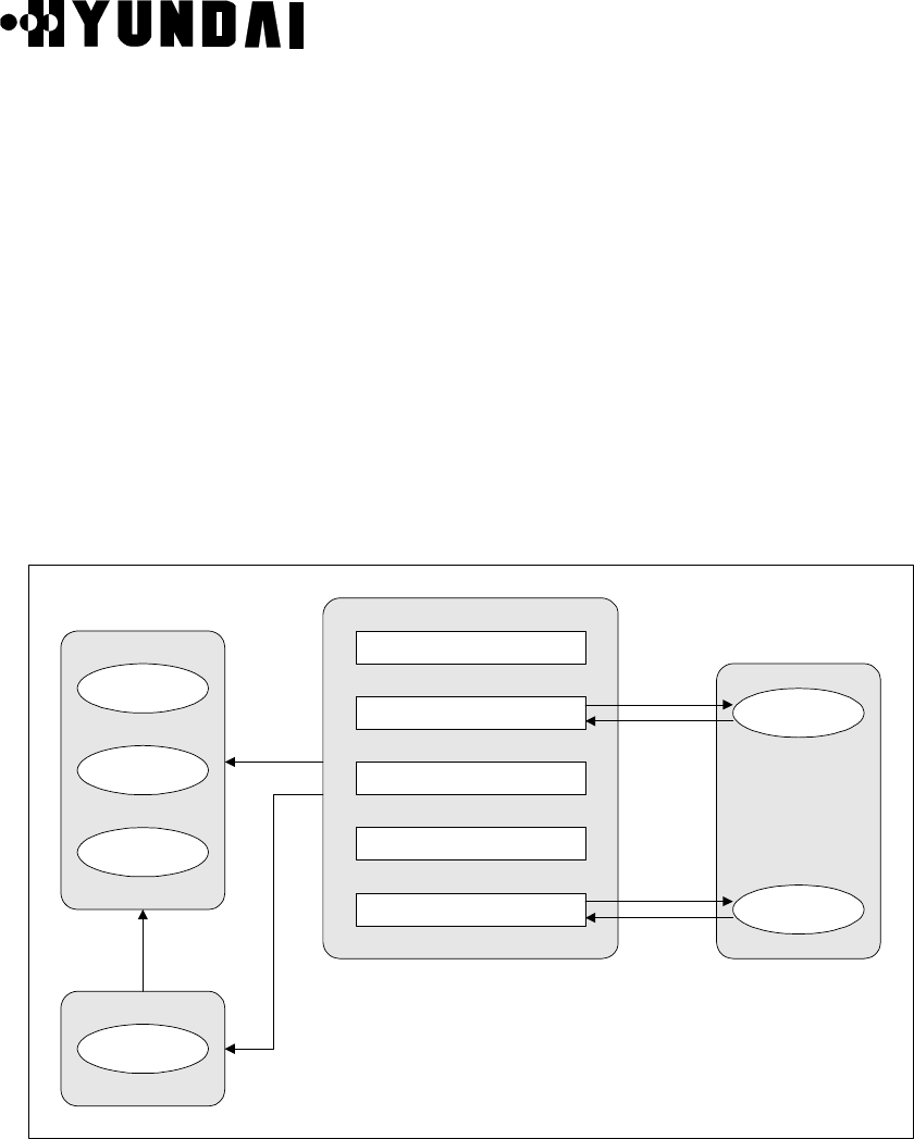
User’s Manual
PROPRIETARY & CONFIDENTIAL
3-143
3.4 Call Processing System
3.4.1 Overview
The call processing is the most important part of system. The call processing fault is very
critical and the related block needs to be always in normal state. It needs to take
emergency measure in the case of call fault.
3.4.2 Call Processing Flow
3.4.2.1 Call Processing Block
TSB
Transmission
BCP
Transmission
PCX
Transmission
Handoff Type
Decision
No.7 Signalling Connection
Vocoder Channel Assignment
Wire&Wireless Section Decision
Conversation State
Call & Resource Release
CCOX Block
Vocoder
Assignment
Vocoder
Release
Message
Transmission
Request
Message
Transmission
Request
Handoff
Handling
Request
Vocoder Assignment
Request
Vocoder Assignment
Response
Vocoder Release
Request
Vocoder Release
Response
Figure 3.62 Call Processing Block Diagram

User’s Manual
PROPRIETARY & CONFIDENTIAL
3-144
The explanation of the Call Processing Block is as follows. ( Refer to Figure 3.62 )
(1) The CCOX, that is call processing block, receives the mobile oriented call from base
station. And, it allocates an available selector in basis of the received trunk information
from MSC. The CCOX establishes the traffic channel path between MSC and mobile
station after it setting the traffic channel up.
(2) The CCOX receives the paging message from MSC and informs mobile station of it.
The CCOX allocates an available selector in basis of the information that MSC sent.
The CCOX establishes the traffic path between MSC and mobile station after it setting
the traffic channel up.
(3) Call is to be in progress after call setup process. CCOX releases call where it receives
call release request from MS or MSC.
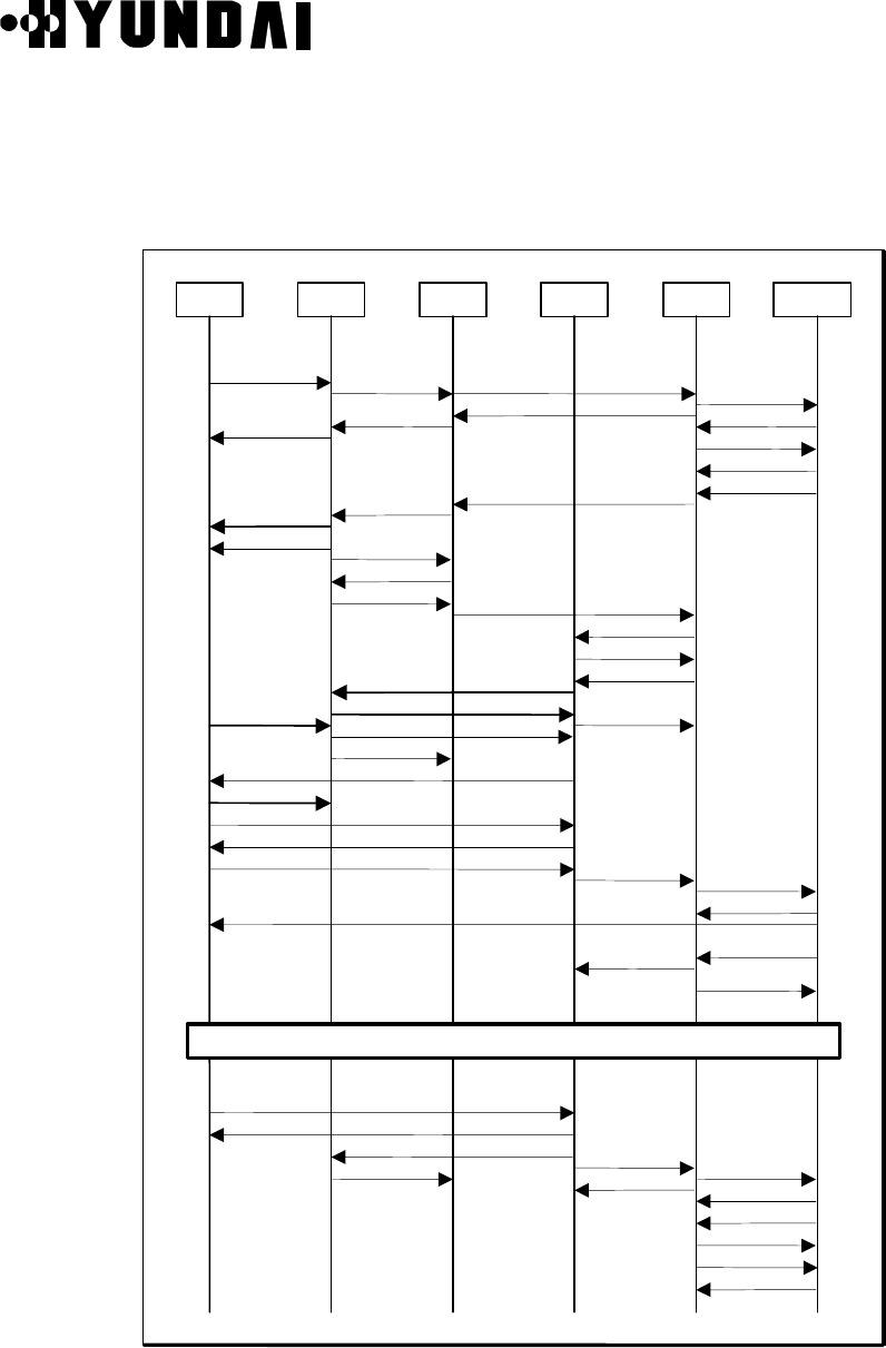
User’s Manual
PROPRIETARY & CONFIDENTIAL
3-145
3.4.2.2 Flow of Mobile Origination Call
The Flow of Mobile Origination Call is equal as follows. ( Refer to Figure 3.63 )
PCXPS CCPTSBBCPCE
Orignation Msg
msg_cm_svc_req_cx
msg_con_conf_xc
msg_call_proc_xc
msg_setup_cx
msg_mob_orig_ack_cb
msg_mob_orig_bc
pc_mob_order_msg
cc_cai_mob_org_msg
BS_Ack_Order
msg_asgn_req_xc
SCCP RLSD
SCCP RLC
Release Order
Release Order
tc_release_ctl_msg
cc_call_rel_msg msg_release_cs
msg_release_sc msg_release_cx
msg_rel_cmpl_xc
msg_clr_cmd_xc
msg_clr_cmpl_cx
msg_alert_xc
msg_connect_xc
msg_connect_cs
Ring Back Tone
msg_connect_ack_cx
Conversation State
tc_mob_assign_msg msg_ch_assign_req_cb
cc_call_status_msg
Ch. Assign Msg
pc_chan_assign_msg
NULL Traffic
Sig_dyn_sve_rsp_sc
msg_vs_tc_cs
sig_dyn_sve_req_cs
cc_msg_tx_ota_msg msg_ch_assign_cmpl_bc
TCh Preamble TIME SYNC
TIME SYNC
msg_link_active_sc
vs_mob_acq_ctl_msg
Service Request Msg.
Service Connect Msg.
Service Connect Complete Msg.
msg_asgn_cmpl_cx
msg_mob_con_sc
cc_call_status_msg
Bs_Ack_Order
NULL Traffic
Figure 3.63 Flow of Mobile Origination Call
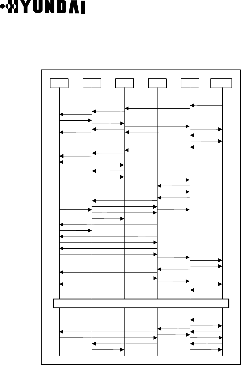
User’s Manual
PROPRIETARY & CONFIDENTIAL
3-146
3.4.2.3 Flow of Mobile Termination Call
The Flow of Mobile Termination Call is equal as follows. ( Refer to Figure 3.64 )
PCXPS CCPTSBBCPCE
tc_mob_assign_msg
msg_ch_assign_req_cb
cc_call_status_msg
Ch. Assign Msg
pc_chan_assign_msg
NULL Traffic
Sig_dyn_sve_rsp_sc
msg_vs_tc_cs
sig_dyn_sve_req_cs
cc_msg_tx_ota_msg
msg_ch_assign_cmpl_bc
TCh Preamble TIME SYNC
TIME SYNC
msg_link_active_sc
vs_mob_acq_ctl_msg
Service Request Msg.
Service Response Msg.
Service Connect Msg.
Service Connect Complete Msg.
msg_asgn_cmpl_cx
msg_mob_con_sc
cc_call_status_msg
Bs_Ack_Order
NULL Traffic
msg_paging_xc
msg_page_mob_cb
pc_page_mob_msg
General Page Msg
Page Response Msg cc_cai_page_response
pc_mob_order_msg msg_page_rsp_bc
msg_page_rsp_ack_cb
msg_page_rsp_cx
msg_setup_xc
msg_asgn_req_xc
msg_call_conf_cx
BS_Ack_Order
Conversation State
msg_alert_cx
msg_alert_cs
Alert With Info (Ring Tone On)
Connect_Order msg_connect_sc
_sc( msg_connect_cx
msg_connect_ack_xc
Bs_Ack_Order
Release Order
Release Order
tc_release_ctl_msg
cc_call_rel_msg
msg_release_cs
msg_release_sc
msg_rel_cmpl_cx
msg_clr_cmd_xc
msg_clr_cmpl_cx
SCCP RLSD
SCCP RLC
msg_release_xc
Figure 3.64 Flow of Mobile Termination Call
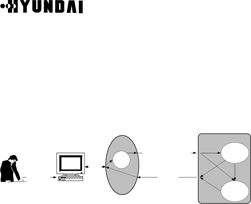
User’s Manual
PROPRIETARY & CONFIDENTIAL
3-147
3.4.3 Call Trace
3.4.3.1 Call Processing Command
By typing some commands in CROS shell, several of information which are related to call
control can be displayed such as call flow, call statistics, and diagnostics.
The general processing flow is as follows. ( Refer to Figure 3.65 )
CROS
BSM Terminal or
CRT Monitor
shell
RS-232
CCOX
sig_call_display_req_init_oc(cd)
sig_call_list_disp_oc(cl)
sig_call_trace_req_oc(ct)
print
cl Command
ct Command
cd Command
CCOX Child
Process
CCOX Main
Process
Command
Figure 3.65 Flow of General Command Processing
By using console (FAST or rcu program operation on the BSM), user can order several
command to shell connected to CCP ( MCDA ) through RS-232C cable. The shell
analyzes the received command and sends the signal which is related with command to
CCP. The CCOX Outmost process receives this signal and executes function requested
by this signal.

User’s Manual
PROPRIETARY & CONFIDENTIAL
3-148
3.4.3.1.1 Call List Command
It displays the origination call and termination call setup process, Handoff process,
Registration process and statistics data, etc.
Usage : cl xx ( ‘xx’ is command option. )
(1) cl 0
It displays call id, IMSI, ESN and process id of call during servicing.
(2) cl 1
It displays call id, IMSI, ESN, and process id of call during servicing and tracing by call
trace command.

User’s Manual
PROPRIETARY & CONFIDENTIAL
3-149
(3) cl 2
It includes ‘cl 0’ and ‘cl 1’ function.
(4) cl 3
This is a Toggle Command. When it is ON, it displays call release in detail. It displays
IMSI, ESN, Process Id, Cause, Call State, Handoff State, and Call Id of released call
for the abnormal release when the specific call is released.
The abnormal call release is a call release expecting normal release, power down and
mobile release.
(5) cl 4
This is a Toggle command. When it is ON, it displays all information. It executes all
inserted print sentence.

User’s Manual
PROPRIETARY & CONFIDENTIAL
3-150
(6) cl 5
This is a Toggle command. When it is ON, it displays data related to statistics.
(7) cl 6
It displays data that are collected about all errors by case.
• STATE : the number of occurrence that the call processing status out of the
originated call, terminated call, Markov call and MSC hard Handoff call
processing shall enter the undefined state on the ground of the Finite
State Machine.
• MSG_ID : the number of occurrence that received the unexpected message at the
specific State.
• VALUE : the number of occurrence that the data value get out of the defined
scope.
• DIFF : Not Used
• SEND : the number of occurrence that fail when send BCP or TSB or MSC to the
signal or message.
• ENCODE : the number of occurrence that the message type of source message
mismatch or a specific field value mismatch to be encoding.
• DECODE : the number of occurrence that the message type of source message
mismatch or a specific field value mismatch to be decoding.
• PROTOCOL : the number of occurrence that the value of specific field in the
Signal or message do not define to standard in use as the
interface between BSC and MSC.

User’s Manual
PROPRIETARY & CONFIDENTIAL
3-151
• PORT : Not Used
• HO_TYPE : Not Used
(8) cl 7
It displays each release cause.

User’s Manual
PROPRIETARY & CONFIDENTIAL
3-152
(9) cl 8
This is a Toggle command. If the registration flow is ON, it displays message flow
which is related with mobile registration.
(10) cl 9
It displays IMSI and Child Process ID on servicing call.
(11) cl 10
It displays the number of traffic call, setup call and Null call.

User’s Manual
PROPRIETARY & CONFIDENTIAL
3-153
(12) cl a
This is a Toggle command. When it is ON, it collects a statistics data every 10 sec. If it
is OFF, it stops a statistics data collection.
(13) cl b
It displays a collected statistics data. It displays the statistics start time and end time
and the statistics items

User’s Manual
PROPRIETARY & CONFIDENTIAL
3-154
(14) cl c
It displays the statistics items which is related with the Softer Handoff. It displays the
statistics start time and end time and the statistics items
(15) cl d
It displays the statistics items which is related with the Soft Handoff. It displays the
statistics start time and end time and the statistics items

User’s Manual
PROPRIETARY & CONFIDENTIAL
3-155
(16) cl e
It displays the statistics items which is related with the Hard Handoff. It displays the
statistics start time and end time and the statistics items
(17) cl 14
This is a Toggle command. When it is ON, it displays this message length when the
CCP send message to MSC.
(18) cl 15 :
It displays the call setup Time average of origination and termination call.

User’s Manual
PROPRIETARY & CONFIDENTIAL
3-156
(19) cl 16
This is a Toggle command. When it is ON, it displays the Origination and Termination
Call Setup time at the unit of milli second.
(20) cl 17
It displays the time elapsed after loading the CCOX. It displays the CCOX start time,
current time and the time elapsed at the unit of year, month, day, hour, minute, and
second.
(21) cl 18
If it receives an invalid message at specific state, it displays this message information.

User’s Manual
PROPRIETARY & CONFIDENTIAL
3-157
(22) cl 19
It sets up Time Interval for counting of the number of signal received by CCOX
outmost Process by using consecutive two ‘cl’ commands.
(23) cl 1a
It displays the number of signal received by CCOX Outmost Process during the
interval time established use of ‘c 19’ command.
(24) cl 1b
It displays the Handoff Processing Time.

User’s Manual
PROPRIETARY & CONFIDENTIAL
3-158
(25) cl 20
It displays the cause of Connection Refuse Cause ( CREF ) and cause value in
corresponding to the CREF.
(26) cl 21
It displays the cause of Connection Release Cause ( RLSD ) and cause value in
corresponding to the RLSD.

User’s Manual
PROPRIETARY & CONFIDENTIAL
3-159
(27) cl 40
This is a Toggle command. When it is ON, it displays Call List message by BTS.
(28) cl 80
This is a Toggle command. When it is ON, it sets L-to-M to 8K.
(29) cl 87
This is a Toggle command. When it is ON, it changes loopback mode to voice loop
mode.

User’s Manual
PROPRIETARY & CONFIDENTIAL
3-160
(30) cl 88
This is a Toggle command. When it is ON, it sets up loopback mode.
(31) cl 99
It displays the status of DSP chips in TSB. ( EQUIP, BUSY, BLOCK )
(32) cl aa
It displays the ON/OFF status of Toggle commands.

User’s Manual
PROPRIETARY & CONFIDENTIAL
3-161
(33) cl b0
It displays the message use of Hard handoff each MSC with each ‘cl’ command.
(34) cl b1
This is a Toggle command. When it is ON, it displays the Handoff Required Message
as the hex code.
(35) cl b2
This is a Toggle command. When it is ON, it displays the Handoff Request Message
as the hex code.

User’s Manual
PROPRIETARY & CONFIDENTIAL
3-162
(36) cl b3
This is a Toggle command. When it is ON, it displays the Handoff Assign(Target)
Message as the hex code.
(37) cl b4
This is a Toggle command. When it is ON, it displays the Handoff Request Ack
Message as the hex code.
(38) cl b5
This is a Toggle command. When it is ON, it displays the Handoff Failure Message as
the hex code.
(39) cl b6
This is a Toggle command. When it is ON, it displays the Handoff Command Message
as the hex code.

User’s Manual
PROPRIETARY & CONFIDENTIAL
3-163
(40) cl b7
This is a Toggle command. When it is ON, it displays the Handoff Required Reject
message as the hex code.
(41) cl b8
This is a Toggle command. When it is ON, it displays the Handoff Assign (serving)
Message as the hex code.
(42) cl b9
This is a Toggle command. When it is ON, it displays the Handoff Commenced
Message as the hex code.
(43) cl ba
This is a Toggle command. When it is ON, it displays the Handoff Complete Message
as the hex code.

User’s Manual
PROPRIETARY & CONFIDENTIAL
3-164
(44) cl bb
This is a Toggle command. When it is ON, it displays the Handoff Clear Command
Message as the hex code.
(45) cl bc
This is a Toggle command. When it is ON, it displays the Handoff Clear Complete (
Serving ) Message as the hex code.
(46) cl bf
It displays the Toggle ON/OFF status of each command form ‘cl b1’ to ‘cl bc’.

User’s Manual
PROPRIETARY & CONFIDENTIAL
3-165
(47) cl da
It displays the tracing Signal Number and Message Number by using of ‘cl da’, ‘cl db’,
and ‘ct’ command.
(48) cl db
It displays the Raw Data of Signal registered by ‘ct’ command as the hex code.
(49) cl dc
It displays the Raw Data of message registered by ‘ct’ command as the hex code.

User’s Manual
PROPRIETARY & CONFIDENTIAL
3-166
(50) cl dd
It stops the signal trace and message trace.
(51) cl f0
It diagnoses the NO.7 Signaling Connection status. It generates child process for the
testing of No.7.
It can be decided the No.7 Link as the normal, if it receives the CREF Message, that
the Cause is 0, by MSC as the test result.
(52) cl ff
It displays the ‘cl’ command list.

User’s Manual
PROPRIETARY & CONFIDENTIAL
3-167
3.4.3.1.2 Call Trace Command
The Call Trace Command is used for tracing the specific MIN number. The Call Trace
command is a function that toggles the call processing flow and Handoff flow of the
selected MIN number.
(1) a specific MIN number ON/OFF Command ( ‘xxxxxxx’ is MIN number. )
<Usage> ct xxxxxxx on/off
(2) call flow of specific MIN number Toggle Command ( ‘xxxxxxx’ is MIN number. )
<Usage> call xxxxxxx
(3) handoff flow of specific MIN number Toggle Command ( ‘xxxxxxx’ is MIN number. )
<Usage> ho xxxxxxx

User’s Manual
PROPRIETARY & CONFIDENTIAL
3-168
3.4.3.1.3 Call Display Command
It displays the information which is related with the basic call information, resource
occupancy state and handoff of call

User’s Manual
PROPRIETARY & CONFIDENTIAL
3-169
3.4.4 Call Release Reason and State
If the call is released in call processing, the CCP in the BSC sends Call fault Message with
the released call information to BSM. The call fault reason and state represent call release
reason and call processing state.
3.4.4.1 Arrangement according to Release Reason
(1) MS/CE/BTS Release
1) REL_MOBILE_RELEASE
It occurs in case that END key of MS is pressed and released.
2) REL_POWER_DOWN
It occurs in case that Power key of MS is pressed and released, or battery of Mobile
Station is run out.
3) REL_SI_LINK_FAIL
It occurs when the data do not exchange between TSB and CE.
4) REL_MARKOV_REL
Not Used
5) REL_TIMEOUT_CCP
If the BCP doesn’t receive ACK message from CCP after the BCP request ACK
message to CCP in the call establishment, it occurs. In case that the BCP doesn’t
receive ACK message from CCP is as follows.
• In case that the CCOX block is in abnormal operation.
• In case that the BLINK between BTS and BSC is in abnormal operation.
• In case of loss of message at the normal state.
6) REL_TIMEOUT_PC
If the BCP doesn’t receive ACK message from PCE after the BCP send Channel
Assign message to PCE in the call establishment, it occurs.
In case that the BCP doesn’t receive ACK message from PCE is as follows.
• In case the PCE is abnormal.
• In case the Router Node/Cable between BCP and PCE is out of order.

User’s Manual
PROPRIETARY & CONFIDENTIAL
3-170
7) REL_TIMEOUT_TC
If the BCP doesn’t receive ACK message from TCE after the BCP send TCE assign
message to TCE in the call establishment, it occurs.
In case that the BCP doesn’t receive ACK message from TCE is as follows.
• In case the TCE is abnormal.
• In case Router Node/Cable between BCP and TCE is out of order.
8) REL_PRE_SERVICE
If Mobile Station requests call with ESN No. which is same as ESN No. in BCP DB
data of old ESN No., new call setup is released .
• In case that the mobile station remains in call because of loss the air message
after the mobile station releases.
• In case that the mobile station requests new call without the mobile station release
in the call establishment.
9) REL_NOT_SETUP
During call processing in BCP, BCP swapping is not completed and call process is
not completed.
10) REL_TEST_CALL
In case of normal release of Test call such as Markov or Loopback.
11) REL_DOWN_ACT_TFC
In case of TFC swapping in base station, all calls are released.
12) REL_TPTL
The Base station releases all calls when TPTL ( Transmit Power Tracking Loop ) is
involved and the Base station stops call service until the TPTL operation
completes.
(2) TSB Release
1) REL_SIGNAL_MSG_TOUT
In case that the message does not exchange properly between mobile station and
TSB. If the TSB doesn’t receive ACK message from mobile station after the TSB
sends a specific message to mobile station, it occurs. If the TSB doesn’t receive
ACK message from mobile station during minimum 4 seconds, it occurs. Because
the TSB resends specific message 10 times a unit of 400 milli-seconds. In case, the

User’s Manual
PROPRIETARY & CONFIDENTIAL
3-171
Reverse Traffic Channel is decided out of order.
2) REL_CONTROL_MSG_TOUT
In case that the message isn’t exchanged between Base station Traffic Channel
Element and TSB. If the TSB doesn’t receive ACK message from the base station
traffic channel element after the TSB sends a specific message to the base station
traffic channel element, it occurs. If the TSB doesn’t receive ACK message from the
base station traffic channel element for minimum 600 mili-seconds, it occurs.
Because the TSB resends to specific message 3 times a unit of 200 mili-seconds.
Call can not be released during handoff.
3) REL_BAD_FRAMES
In case of receiving 250 bad frames from mobile station. The cause is as follows.
• In case of releasing the call because of bad forward traffic channel.
• In case of bad Reverse Traffic Channel.
• In case of removing the battery of mobile station.
4) REL_MOB_NOT_ACQ
If it doesn’t receive Mobile_Acquire message from base station traffic channel
element in 5 minutes of the call establishment, it occurs. Also, it occurs at specific
TCE because of H/W problem.
5) REL_TIME_SYNC_TOUT
If it doesn’t receive Time Sync Packet from base station traffic channel element in 1
second of the call establishment, it occurs. That is, in case that the TSB doesn’t
receive ACK message to Time Sync Packet. Also, it is possible to occur by the Trunk
problem between the Base Station and the Base Station Controller or a specific
Vocoder.
6) REL_SO_REJECTED
In case that the Service Option does not agree between mobile station and TSB. In
case that the mobile station release as the Service Option Reject. If the TSB sends
undefined Service Option Number to mobile station, it occurs.
7) REL_SOFT_DROP
Not Used.
8) REL_INTRA_HARD
Not Used
9) REL_INTER_HARD

User’s Manual
PROPRIETARY & CONFIDENTIAL
3-172
Not Used.
10) REL_FRAME_OFFSET_HARD
Not Used.
11) REL_INTER_MSC_HARD
Not Used.
12) REL_NO_MARKOV_SYNC
If mobile station and TSB do not exchange the valid Markov Frame in a constant
time out of Markov call setup, it occurs. At the current system, the call isn’t released
as this cause.
13) REL_SO2_NO_SYNC
If mobile station and TSB do not exchange the valid Loopback Frame in a constant
time out of Service Option 2 Call Setup, it occurs. The Service Option 2 Sync
means to start point of Loop back statistic.
14) REL_NO_FRAMES
If it doesn’t receive Traffic Frame from Traffic Channel Element for 2 seconds , it
occurs. It can be the trunk problem between base station and base station
controller or the base station traffic channel card is out of order.
15) REL_INVALID_VOCID
If the TSB receives Vs_Tc_Cs Message from CCP with the appropriate channel
being used, the TSB sends NOK message to CCP. By this time the CCP does not
release the call and reallocate the resource. If this state is occurred again, the CCP
clear the call.
16) REL_SERV_NEGO_MSG_TOUT
In case that the Service Negotiation Procedure doesn’t receive the Service
Response Message or Service Connect Complete Message from mobile station
within the defined time.
(3) CCP / MSC Release
1) RCV_MSG_TIME_OUT
In case that the CCP doesn’t receive a specific message within the defined time, it
occurs. That is,
• In case that the CCP doesn’t receive the Link_Active_Sc within 10 seconds after

User’s Manual
PROPRIETARY & CONFIDENTIAL
3-173
the CCP receives the Link_Active_Sc
• In case that the CCP doesn’t receive the Mob_Connect_Sc within 10 seconds after
the CCP receives the Link_Active_Sc
• In case that the CCP doesn’t receive the Call_Proc_Xc within 10 seconds after the
CCP sends Setup_Cx
• In case that the CCP doesn’t receive the Alert_Xc within 60 seconds after the CCP
receives Call_Proc_Xc
• In case that the CCP doesn’t receive the Connect_Sc within 40 seconds after the
CCP sends Alert_info_Cs
• In case that the CCP doesn’t receive the Connect_Xc within 40 seconds after the
CCP sends Alert_info_Cs
2) REL_DB_SEL_FAIL
In case that the Tuple status of the appropriate PLD is not 0xff, that is Not Equip,
when handles each kind of data to read the PLD.
3) REL_OVERLOAD
It checks the overload of the Vocoder, TCE, CCP Processor, and BCP Processor in
the status block at the originated call, terminated call and Handoff attempt. If they
have overload, it stops the call attempt. If the CCP Overload is, it change to BTS
Overload.
4) REL_VOC_SIP_UNAVAIL
In case that it fails to allocate the Vocoder resource when all IA resources of TSB
Vocoder are Not Equip or Abnormal, or Block at the originated call, terminated call
and Test Call setup.
5) REL_VOC_SVP_UNAVAIL
In case that it fails to allocate the Vocoder resource when all OA resources of TSB
Vocoder are Not Equip or Abnormal, or Block at the originated call, terminated call
and Test Call setup.
6) REL_VOC_SVE_UNAVAIL
In case that it fails to allocate the Vocoder resource when all DSP resources of TSB
Vocoder are Not Equip or Abnormal, or Block at the originated call, terminated call
and Test Call setup.
7) REL_TRK_UNAVAIL
The Trunk uses 24 channels T1 Trunks in case that it fails to allocate the Vocoder

User’s Manual
PROPRIETARY & CONFIDENTIAL
3-174
resource when all Trunk resources are Not Equip or Abnormal, or Block at the
originated call, terminated call and Test Call setup.
Actually, the status block reports IA status to Abnormal. So, the Release Reason is
REL_VOC_SIP_UNVAIL.
8) TSB_BOARD_RESET
Not Used.
9) REL_MX_PROTOCOL_ERR
In case that a defined field value is mismatch in advance or gets out of a scope out
of message received by MSC.
10) CPS_ALREADY_USED
Not Used.
11) REL_TER_DGT_ERR
In case that Called Digits of a receiving part are under a number of 2 figures at the
originated call attempt.
12) NORMAL_REL
In case that the call is released normally by pressing the End Key of the opposite
mobile station normally.
13) USER_BUSY
In case that the opposite subscriber is on busy.
14) USER_NO_ANSWER
In case that it doesn’t receive the Connect message within 1 minutes after
receiving the Alert message.
15) UNASSIGN_NUM
Not Used
16) POWER_DOWN
In case that the power is exhausted or power off by the opposite Party
17) ABN_REL
In case of the Mlink fail, Handoff fail and Processor down, etc.
18) CREF
The NOK toward to Setup Cx as the simpler form for the Connection Refuse.
If the appropriate mobile station is not the mobile station registered or occurs the
each kind of alarm in the MSC, it occurs. If the given Trunk Channel for call
processing at BSC is Block, it occurs.

User’s Manual
PROPRIETARY & CONFIDENTIAL
3-175
19) MSC_RESET
In case that MSC can not process the call any more because of reseting the MSC
for some reason or other.
20) REL_TC_UNAVAIL
In case that it can not allocate the TCE resource because there is no available TCE
resources during the originated call and terminated call attempt.
21) REL_CODE_CH_UNAVAIL
In case of no available the Code Channel at the originated and terminated call
attempt, the BCP prevents the call attempting to the CCP and sending CCP to
Reason message.
22) REL_FRAME_OFFSET_UNAV
In case of no available the Frame Offset at the originated and terminated call
attempt, the BCP prevents the call attempting to the CCP and sending CCP to
Reason message.
23) REL_ALL_BLINK_UNAV
In case of unavailable for the Blink at the originated and terminated call attempt,
the BCP prevents the call attempting to the CCP and sending CCP to Reason
message.
24) REL_BTS_OVLD_STS
If the load of the CCP or BCP Processor occurs more than threshold or occurs the
CCP Overload , it decides the BCP Overload.
In this case, the BCP prevents the call attempting to the CCP and sending CCP to
Reason message.
25) REL_HOFF_FAIL
Handoff Failure
26) REL_SENDSIG_FAIL
In case that the transmission of message is failed by the IPC block appearance or
the appropriate Destination Address mistake or killed status of the Destination
Process when the CCP sends MSC, TSB, BCP to message.
27) REL_FULL_ACT_CELL
In case that it can not be to add the PN pilot in the Active set because the base
station has 3 PN pilots in the Active set at the Handoff operation.

User’s Manual
PROPRIETARY & CONFIDENTIAL
3-176
28) REL_HOFF_NBR_DATA_ERR
In case that the BTS_ID of Reference PN pilot is equal to the BTS_ID of PN pilot to
be add at the Soft Handoff operation.
29) REL_MSG_DATA_ERR
In case that the BCP sends CCP to UNDEFINED_ALLOC_MODE after the BCP is
received the undefined Alloc Mode at the Handoff operation.
30) REL_TEST_CALL_NO_RSP
In case of no response toward to the Paging at the Markov or Loopback is equal to
Test Call attempt.
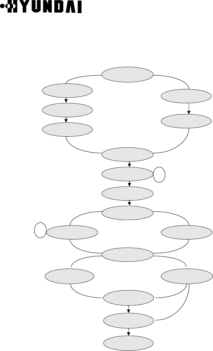
User’s Manual
PROPRIETARY & CONFIDENTIAL
3-177
3.4.4.2 Call State
The Call State Flow of the Call Processing is as follows. ( Refer to Figure 3.66 )
msg_mob_orig_cc TER_INIT_STATE
COM_ ASSIGN_REQ_STATE
COM_LINK_ACTIVE_STATE
COM_MOB_CON_STATE
ORG_ ALERT_N_
CONNECT_STATE TER_CONNECT_STATE
TRAFFIC_STATE
REL_CONF_STATE
REL_CLR_CMD_STAT
E
REL_SCBC_CLR_STATE
NULL_STATE
msg_mob_orig_cc msg_page_response_cc
msg_page_rsp_cc
msg_setup_xc
msg_call_proc_xc
_sig_cc_xc
msg_asgn_req_xc
msg_mob_connect_sc
msg_clr_cmd_xc
sig_rlsd_xc
msg_release_sc or
msg_release_bc
msg_release_sc and/or
msg_release_bc
msg_clr_cmd_xc
msg_connect_sc
msg_release_xc
msg_rel_cmpl_xc
msg_connect_xc
msg_alert_xc
msg_mob_connect_sc
msg_link_active_sc
msg_ch_asgn_cmpl_bc
sig_dyn_sve_req_cs
sig_ dyn_sve_rsp_sc
NULL_STATE
ORG_CON_CONF_STATE
TER_SETUP_STATE
ORG_CALL_PROC_STATE
COM_ASSIGN_CMPL_STATE
REL_SCCP_RLSD_STATE
ORG_INIT_STATE
Figure 3.66 Call State Flow

User’s Manual
PROPRIETARY & CONFIDENTIAL
3-178
(1) NULL_ STATE
Initialization State : If the Origination Message is received at Initialization State, the
CCP shall enter the ORG_INIT_STATE. Upon entering the ORG_INIT_STATE, the
Child process is generated by Main process and the Main process send the Origination
Message to the Child process.
(2) ORG_INIT_STATE
The CCP shall enter the ORG_CON_CONF_STATE after the CCP store the received
origination information and send Acknowledge to BCP toward to the Origination
Message and send the CM Service Request Message to MSC.
(3) ORG_CON_CONF_STATE
The CCP sends the Authentication Request Message to BCP after it receives the
Authentication Request Message from MSC. If the CCP is received the Authentication
Challenge Response from the mobile station by BCP, the CCP sends MSC to the
Authentication Response Message. The MSC sends to the Setup Message after
receives the Authentication Response Message from CCP.
(4) ORG_CALL_PROC_STATE
If the CCP receives the Call Proceeding Message from MSC, the CCP stores the
Alerting Information and shall enter the ORG_CALL_PROC_STATE.
(5) TER_INIT_STATE
If the CCP receives the Paging Response Message from BCP, the CCP shall enter the
TER_INIT_STATE after sending BCP to the Paging Response Ack and sends MSC to
the Paging Response Message.
(6) TER_SETUP_STATE
If the CCP receives the Setup Message from MSC, the CCP shall enter the
COM_ASSIGN_REQ_STATE after storing the Alert information and send MSC to the
Call Confirmation Message.
(7) COM_ASSIGN_REQ_STATE
If the CCP receives the Assignment Request Message from MSC, the CCP shall enter
the COM_ASSIGN_CMPL_STATE after storing the Trunk information and Service
Option information and send the Channel Assignment Request Message to BCP.
(8) COM_ASSIGN_CMPL_STATE
The CCP stores the Channel Allocation information from BCP and send TSB to the
Dynamic SVE Request Message. If the CCP receives the Dynamic SVE Response

User’s Manual
PROPRIETARY & CONFIDENTIAL
3-179
Message from TSB toward to the Dynamic SVE Request Message, the CCP shall enter
the COM_LINK_ACTIVE_STATE after sending the Vs Tc Message to TSB.
(9) COM_LINK_ACTIVE_STATE
If the CCP receives the message, that the message activated , from TSB, the CCP
shall enter the COM_MOB_CON_STATE.
(10) COM_MOB_CON_STATE
The CCP stores the Service Configuration conferred and send the Assignment
Complete Message to MSC.
If it is the Origination Call , the CCP shall enter the ORG_ALERT_N_CONNECT_
STATE. If it is not the Origination Call, the CCP waits the Transcoder Control
Message to be receive from MSC. If the CCP receives the Transcoder Control
Message from MSC, the CCP shall enter the TRAFFIC_STATE after the CCP store
the Transcoder Mode information and sends the Acknowledge Message to MSC and
Alert Message and sends the Alert Info Message to TSB.
(11) ORG_ALERT_N_CONNECT_STATE
If the CCP receives the Alerting Message from MSC, the CCP wait the Connect
Message to be receive from MSC after send the Alert with Information Message to
TSB. If the CCP receives the Alert with Information Message from MSC, the CCP
shall enter the TRAFFIC_STATE after send Connect Acknowledge Message to MSC
and send the Connect Message to TSB.
(12) TER_CONNECT_STATE
If the CCP receives the Connect Message from TSB, the CCP sends the Connect
Message to MSC and waits to the Connect Ack Message. If the CCP is received the
Connect Ack Message, the CCP shall enter the TRAFFIC_STATE.
(13) TRAFFIC_STATE
A practical data is transferred. And if the CCP receives the Release Message from
TSB, the CCP shall enter the REL_CONF_STATE. If the CCP receives the Release
Message from MSC, the CCP shall enter the REL_SCBC_CLR_STATE.
(14) REL_CONF_STATE
The CCP receives the Release Complete Message from MSC, the CCP shall enter
the REL_CLR_CMD_STATE.
(15) REL_SCBC_CLR_STATE
If the CCP receives the Release Message from TSB, the CCP shall enter the

User’s Manual
PROPRIETARY & CONFIDENTIAL
3-180
REL_CLR_CMD_STATE.
(16) REL_CLR_CMD_STATE
If the CCP receives the Clear Complete Message from MSC, the CCP sends the
Clear Complete Message to MSC and the CCP completes the call.
If the CCP receives the RLSD Message from MSC, the CCP completes the call
(17) REL_SCCP_RLSD_STATE
Not Used
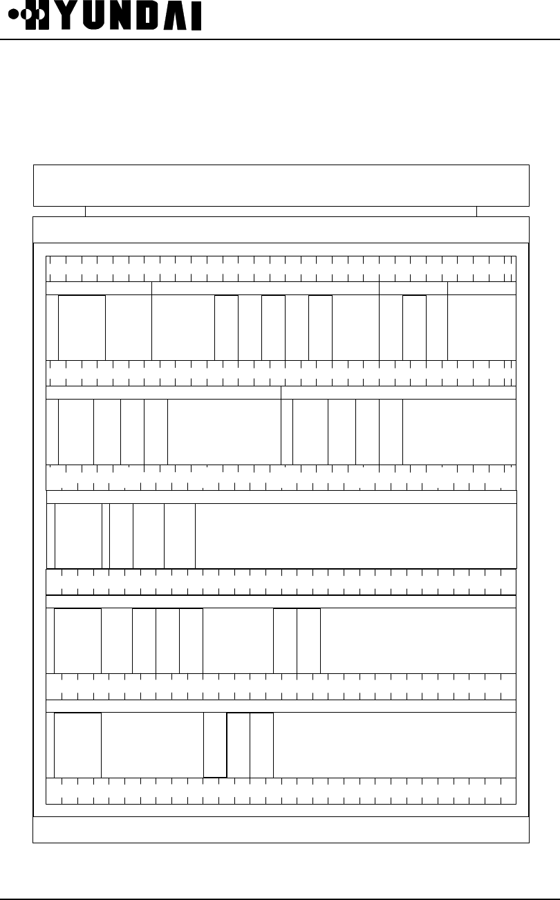
User’s Manual
PROPRIETARY & CONFIDENTIAL 4-1
Chapter 4. BSC References
4.1 Rack Configuration
FAN
FAN
CHBB-A1
HSBB-A1
GUBB-A1 BABB-A1
T
F
S
A
-
A1
T
S
G
A
-
A1
T
F
D
A
-
A1
A
C
P
A
-
A1
H
P
U
-
M
H
I
C
A
-
A2
H
R
N
A
-
A2
H
R
N
A
-
A2
H
N
-
A
-
A2
H
I
C
A
-
A2
H
R
N
A
-
A2
H
P
U
-
M
2 10 20 30 40 50 58
2 10 20 30 40 50 58
2 10 20 30 40 50 58
2
10 20 50 594030
5810 20 30 40 50
00
GTFU-A1
10 20 50 59403000
10 20 50 59403000
CCBB-A1
C
I
F
A
-
A1
M
C
D
A
H
P
U
-
N
CCBB-A1
C
I
F
A
-
A1
M
C
D
A
H
P
U
-
N
SDBB-A1
COMRCOMR
TSBB-A1
H
P
U
-
L
V
S
I
A
-
C1
V
S
O
A
-
A1
V
S
O
A
-
A1
H
R
N
A
-
A2
H
R
N
A
-
A2

User’s Manual
PROPRIETARY & CONFIDENTIAL 4-2
4.2 DIP Switch & Strap
4.2.1 Summary
This section data provides setting method of STRAP/DIP SWITCH for system based
on strap drawing.
4.2.2 Purpose
The purpose of this section is to provide correct usage and setting method to set of
DIP switch and jumper switch on Back Board and on PBA when set up and to notify
caution required during setting.
4.2.3 Address setting in common
• Pin number starts from left on Board as 1
• Deletion of shunt means “1” and insertion of shunt means “0”
• OFF state of DIP switch means “1” and ON state of DIP switch means “0”
Place the switch as ON state (i.e., When Move Up or Right) means “0”
ON
OFF
OFF State ("1")
ON
OFF
ON State ("0")
State of Deletion ("1")
State of Insertion ("0")

User’s Manual
PROPRIETARY & CONFIDENTIAL 4-3
4.2.4 MCDA (Main Control & Duplication Board Assembly)
4.2.4.1 Mounting Drawing
1 2
1
2
1 2
J2
JP2
JP3
JP4
4.2.4.2 Setting
No. Description Normal Config.
JP2
Set CROUT(OS Running Time Out Period)
1. 1.38 sec
2. 2.76 sec
2-ON
JP3
Set MFP Operation Clock
1. 3.9MHz
2. 3.039MHz
2-ON
JP4 JTAG
J2 2. GND 2-ON

User’s Manual
PROPRIETARY & CONFIDENTIAL 4-4
4.2.5 CIFA-A1 (CIN Interface Function board Assembly-A1)
4.2.5.1 Mounting Drawing
JP1 12
4 3
JP10 1 2
4 3
JP12 1 2
4 3
JP13
1
2
JP11
1 5
10 6
CON1
1 9
2 10
JP3 1 2
4 3
JP2
1 6
12 7
JP6
1
2JP5 1 2
43
JP7 1 2
4 3
JP8
1 5
10 6
JP9
1
2
4.2.5.2 Setting
No. Description Normal Config.
JP1
VIACK DELAY TIME SELECTION
1-4 : 50ns
2-3 : 100ns
1 - 4 : 50ns
JP2 VME DPRAM ADDRESS COMPARE
3 - 10
5 - 8
6 - 7

User’s Manual
PROPRIETARY & CONFIDENTIAL 4-5
No. Description Normal Config.
JP3 DMOD SELECTION
1-4 : DMOD1 (STN/DIRECT)
2-3 : DMOD0 (ACT/SBY)
1 - 4 : DMOD1
JP5
RX CLK INVERT SELECTION
1-4 : INVERT
2-3 : NON-INVERT
1 - 4 : INVERT
JP6 1 - 2 : RX CLK SELECTION NC
JP7
TX CLK SELECTION
1 - 4 : INVERT
2 - 3 : NON INVERT
1 - 4 : INVERT
JP8
TX CLK TIME SELECTION
1 - 10 : 20MHz
2 - 9 : 10 MHz
3 - 8 : 5 MHz
4 - 7 : 2.5 MHz
5 - 6 : 1.2 MHz
4 - 7 : 2.5 MHz
JP9 1 - 2: PVAILD ENABLE/DISABLE NC
JP10 1 - 4 : DMA REQUEST A
2 - 3 : DMA REQUEST B 2 - 3
JP11
1-10 : JTAG 1149.1 Boundary Scan Interface TRST
2 - 9 : JTAG 1149.1 Boundary Scan Interface TDI
3 - 8 : JTAG 1149.1 Boundary Scan Interface TDO
4 - 7 : JTAG 1149.1 Boundary Scan Interface TMS
5 - 6 : JTAG 1149.1 Boundary Scan Interface TCK
All Starp
JP12 1 - 4 : INTR1 (ENDPKT)
2 - 3 : INTR2 (SHIRQ)
2 - 3 : INTR2
JP13 1 - 2 : CPU RESET ENABLE/DISABLE NC
CONN1 JTAG FOR FUSING MACH445 NC

User’s Manual
PROPRIETARY & CONFIDENTIAL 4-6
4.2.6 HICA-A2 (High capacity IPC Control Board Assembly-A2)
4.2.6.1 Mounting Drawing
J1
1
5
10
6
4.2.6.2 Setting
No. Description Normal Config.
J1
1-4, 7-10 : NO STRAP (XLINK LOADING FROM
XCHECKER CABLE)
5,6 : STRAP (XLINK LOADING FROM PROM)

User’s Manual
PROPRIETARY & CONFIDENTIAL 4-7
4.2.7 HRNA-A2 (High performance Routing Node Assembly-A2)
4.2.7.1 Mounting Drawing
1 12
2 11
3 10
4 9
5 8
6 7
1 12
2 11
3 10
4 9
5 8
6 7
J6 J4
NODE1 NODE2
1 12
2 11
3 10
4 9
5 8
6 7
1 12
2 11
3 10
4 9
5 8
6 7
J7 J5
NODE3 NODE4
1 12
2 11
3 10
4 9
5 8
6 7
1 12
2 11
3 10
4 9
5 8
6 7
J8 J2
NODE5 NODE6
1 12
2 11
3 10
4 9
5 8
6 7
1 12
2 11
3 10
4 9
5 8
6 7
J9 J3
NODE7 NODE8 8
17
26
35
4J1
1.25M
10M
HRNA-A2 Strapping Drawing
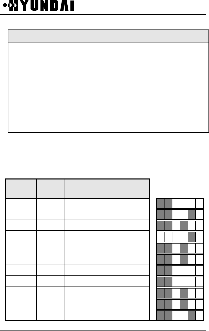
User’s Manual
PROPRIETARY & CONFIDENTIAL 4-8
4.2.7.2 Setting
No. Description Normal Config.
J1
Choose INODECLK
1 - 8 : 10MHz 2 - 7 : 5MHz
3 - 6 : 2.5MHz 4 - 5 : 1.25MHz
1 - 8
J2 – J9
1-12 : INTERFR 1
2-11 : INTERFR 0
3-10 : UCLKSEL (Open=URXC, Short=INODECLK)
4-9 : UBABO (Open=RXA Enable, Short= Disable)
5-8 : FLAG (OPEN=IDLE, SHORT=FLAG)
6-7 : EQUIP (OPEN=EQUIP, SHORT=NOT EQUIP)
Node Setting
• J2 – J9 : Node setting Method for GCIN,LCIN Operation
( J2 : NODE 1, J5 : NODE 2, J3 : NODE 3 , J4 : NODE 4, J6: NODE 5 , J9: NODE
6,
J7: NODE 7 , J8: NODE 8 )
• LCIN Node Setting
SUB-SYSTEM FRAME
Interval
CLOCK
MODE
ALARM
MASK IDLE DATA (Up) JUMPER (Down)
HICA-A2 30 byte external OFF 1
CCP 30 byte external OFF flag
ACP 30 byte external ON 1
TSB 6 byte external OFF flag
DM 30 byte external ON 1
CKD 30 byte external ON 1
BSM 30 byte external OFF 1
TFSA 30 byte external OFF 1
LOG 30 byte external ON 1
ENV 30 byte external ON 1
CSB, CSL 30 byte external OFF flag

User’s Manual
PROPRIETARY & CONFIDENTIAL 4-9
4.2.7.3 Reference Explanation
(1) J1 : U-LINK Clock Speed Adjust ( When ON )
1 – 8 : 10 MHz
2 – 7 : 5 MHz
3 – 6 : 2.5 MHz
4 – 5 : 1.25 MHz
(2) J2 – J9 : Inter frame of each NODE, U-Link clock select, U-Link alarm mask
selection, Transmission flag selection, EQUIP selection
l J2 – J9 ( 1 – 12, 2 – 11 ) : Adjust data frame to maximum length which can be
received according to FRSIZE0, 1 at U-Link ( ON : Low, OFF : High )
FRSIZE1 ( 1 – 12 ) FRSIZE0 ( 2 - 11 ) Data Length
H H 512 Byte
HL768 Byte
LH1280 Byte
L L 2304 Byte
l J2 – J9 ( 3 – 10 ) : Choose U-Link transmission clock between U-Link receive
clock and internal clock ( ON : Use internal clock, OFF : Use U-Link receive clock )
l 2 – J9 ( 4 – 9 ) : Choose U-Link receive alarm mask ( ON : alarm mask, OFF :
NODE control by alarm )
l J2 – J9 ( 5 – 8 ) : Choose inter frame transmission flag. ( ON : flag transmission,
OFF : idle transmission )
l J2 – J9 ( 6 – 7 ) : Choose Equipment of NODE. ( ON : NODE available, OFF :
NODE not available )

User’s Manual
PROPRIETARY & CONFIDENTIAL 4-10
4.2.8 HNTA-A2 (High performance IPC Node & T1 Interface
Assembly-A2)
4.2.8.1 Mounting Drawing
1~10 : OFF = B8ZS, ON = AMI
1
10
2
9
3
8
4
7
5
6
J1
2~9 : OFF = SF framing
3~8 : ON = Use XC5210 SERIAL ROM
(When cutting off of 3-8 connect line
of PCB)
4~7 : ON = XC5210 X-CHECKER CABLE
5~6 : Use
1~8 : 2128 PROGRAM
CABLE
1
16
2 3 4 5
J2
9~16 : 5210 X-CHECKER
CABLE
6 7 8
9
101112131415
* PIN 1,16 : VCC
ON = ESF framing
116
2
3
4
J4
13
14
15
512
6
7
8 9
10
11
116
2
3
4
J3
13
14
15
512
6
7
8 9
10
11
TRUNK1
TRUNK2
TRUNK3
TRUNK4
TRUNK5
TRUNK6
TRUNK7
TRUNK8
J3,J4 : TRUNK CABLE LENGTH SETTING
(EACH TRUNK 2 JUMPER)
ALL OFF : 110 ft
UPPER ON : 220 ft
LOWER ON : 440 ft
ALL ON : 660 ft
4.2.8.2 Setting
• J1 (Adjust for Operation MODE)
No. Description Normal config.
1 ~ 10 Choose T1 Line Coding.
OFF = B8ZS, ON = AMI -
2 ~ 9
Choose Framing.
OFF = SF (D3/D4) framing
ON = ESF Framing
-

User’s Manual
PROPRIETARY & CONFIDENTIAL 4-11
No. Description Normal Conifg.
3 ~ 8
Set ON when using Serial ROM at EPLD 5210
Loading. Because 3~8 is shorted originally in
PCB, jumper setting is not required when line is
not cut off.
ON = Use XC5210 Serial ROM
(Cutting off of 3 ~ 8 Connection Line of PCB)
-
4 ~ 7
Set ON when using X-checker at EPLD 5210
Loading. Because 3~8 are shorted originally, cut
off 3~8 on PCB and set jumper.
ON = Use XC5210 X-CHECKER CABLE.
-
5 ~ 6 - -
• J2 (For EPLD Loading)
No. Description Normal Config.
1 ~ 8 Connect Cable during programming EPLD 2128
(U43). 2128 PROGRAM CABLE -
9 ~ 16 Connect Cable during Programs EPLD 5210
(U18) Loading. 5210 X-CHECKER CABLE -
PIN 1, 16 : VCC

User’s Manual
PROPRIETARY & CONFIDENTIAL 4-12
• J4 (trunk 1~4 length setting)
No. Description Normal Config.
1~16
2~15
(TRUNK 1 LENGTH SETTING)
ALL OFF : 110ft, 1~16 ON : 220ft
2~15 ON : 440ft, ALL OFF : 660ft
-
3~14
4~13
(TRUNK 2 LENGTH SETTING)
ALL OFF : 110ft, 3~14 ON : 220ft
4~13 ON : 440ft, ALL OFF : 660ft
-
5~12
6~11
(TRUNK 3 LENGTH SETTING)
ALL OFF : 110ft, 5~12 ON : 220ft
6~11 ON : 440ft, ALL OFF : 660ft
-
7~10
8~9
(TRUNK 4 LENGTH SETTING)
ALL OFF : 110ft, 7~10 ON : 220ft
8~9 ON : 440ft, ALL OFF : 660ft
-
• J3 (trunk 5~8 length setting)
No. Description Normal Config.
1~16
2~15
(TRUNK 5 LENGTH SETTING)
ALL OFF : 110ft, 1~16 ON : 220ft
2~15 ON : 440ft, ALL OFF : 660ft
-
3~14
4~13
(TRUNK 6 LENGTH SETTING)
ALL OFF : 110ft, 3~14 ON : 220ft
4~13 ON : 440ft, ALL OFF : 660ft
-
5~12
6~11
(TRUNK 7 LENGTH SETTING)
ALL OFF : 110ft, 5~12 ON : 220ft
6~11 ON : 440ft, ALL OFF : 660ft
-
7~10
8~9
(TRUNK 8 LENGTH SETTING)
ALL OFF : 110ft, 7~10 ON : 220ft
8~9 ON : 440ft, ALL OFF : 660ft
-

User’s Manual
PROPRIETARY & CONFIDENTIAL 4-13
4.2.9 TFSA-A1 (Time & Frequency Split Assembly-A1)
4.2.9.1 Mounting Drawing
1
3
5
7
9
2
4
6
8
10
JP2
1
2
3
JP3
2
4
6
8
JP1
1
3
5
7
1
3
5
J1
2
4
6
J2
1
3
5
2
4
6
4.2.9.2 Setting
No. Description Normal Config.
JP1
Loop-back Test of SCC1
1-2 : HDLC-RX_DATA
3-4 : HDLC-TX_DATA
5-6 : HDLC-RX_CLK
7-8 : HDLC-TX_CLK
1-2 : HDLC-RX_DATA
3-4 : HDLC-TX_DATA
5-6 : HDLC-RX_CLK
7-8 : HDLC-TX_CLK
JP2
EPLD Fusing Connect
1-2 : MACH FUSING J-TAG
3-4 :MACH FUSING J-TAG
5-6 : MACH FUSING J-TAG
7-8 : MACH FUSING J-TAG
9-10 : MACH FUSING J-TAG
NC

User’s Manual
PROPRIETARY & CONFIDENTIAL 4-14
No. Description Normal Config.
JP3
RAM Chip Selection
1-2 : Test Setting
2-3 : MACH RAM Chip Selection
2-3 : MACH RAM Chip
Selection
J1
GPS 1PPS-INX Input Level Setting
1-2 : 50ohm Pull-Down
3-4 : 100ohm Pull-Down
5-6 : 150ohm Pull-Down
1-2 : 50ohm Pull-Down
J2
GPS 1PPS-INY Input Level Setting
1-2 : 50ohm Pull-Down
3-4 : 100ohm Pull-Down
5-6 : 150ohm Pull-Down
1-2 : 50ohm Pull-Down

User’s Manual
PROPRIETARY & CONFIDENTIAL 4-15
4.2.10 TSGA-A1 (Time & frequency Splitting Generation Assembly-
A1)
4.2.10.1 Mounting Drawing
JP3
2
4
6
8
10
12
14
16
18
20
1
3
5
7
9
11
13
15
17
19
JP4
2
4
6
8
10
1
3
5
7
9
JP2
4
23
1
JP1
4
23
1
J1
1
2
3
4.2.10.2 Setting
No. Description Normal Config.
J1
Internal Oscillator Setting
1-2 : Use Y1 internal Oscillator for
test
2-3 : Use 10MHz from external
2-3 : Use 10MHz from
external
JP1
1PPS input resistance Setting
1-2 : 300_ohm
3-4 : 10_ohm
1-2 : 300_ohm
JP2
1PPS input resistance Setting
1-2 : 300_ohm
3-4 : 10_ohm
1-2 : 300_ohm

User’s Manual
PROPRIETARY & CONFIDENTIAL 4-16
No. Description Normal Config.
JP3
Clock Test Pin
2 : 2.048MHz SIGNAL
3 : 1.544MHz SIGNAL
4 : 8KHz SIGNAL
5 : 50Hz SIGNAL
6 : FOI SIGNAL
7 : 4.096MHz SIGNAL
8 : SUB SIGNAL
9 : ADD SIGNAL
10 : 50Hz RESET SIGNAL
11 : ADDA SIGNAL
12 : ADDPPS SIGNAL
13 : GPS_RST SIGNAL
14 : PPS_RST SIGNAL
19 : DLY_PPS SIGNAL
20 : 1PPS SIGNAL
NC
JP4 MACH_FUSING J_TAG NC

User’s Manual
PROPRIETARY & CONFIDENTIAL 4-17
4.2.11 TFDA-A1 (Time & Frequency Distribution Assembly-A1)
4.2.11.1 Mounting Drawing
J1
2
4
6
8
10
12
14
16
18
20
1
3
5
7
9
11
13
15
17
19
4.2.11.2 Setting
No. Description Normal Config.
J1
Signal Check
2 : FOI SIGNAL
4 : 2.048MHz SIGNAL
6 : 4.096MHz SIGNAL
8 : 50Hz SIGNAL
10 : 1.544MHz SIGNAL
NC

User’s Manual
PROPRIETARY & CONFIDENTIAL 4-18
4.2.12 VSIA-C1 (Vocoder Selector Interface Assembly-A1)
4.2.12.1 Mounting Drawing
JP 16
1 4
8 5
JP 5
1 4
8 5
JP 2
JP 7
1 5
10 6
1
2
JP 9
1 2
4 3
JP 8
1 2
4 3
JP 17
1 4
8 5
JP 18
1 4
8 5
JP 19
1 4
8 5
JP 20
1 4
8 5
JP 24
14 8
1 7
JP 23
14 8
1 7
JP
26
1 2
4 3
JP
25
1 2
4 3
4
3
JP 3
1
4
8
5
JP 6
1 2
4 3
JP 11
1 5
10 6
JP 12
1 4
8 5
JP
13
1 2
4 3
JP
14
1 2
4 3
JP
15
1 2
4 3
JP 10
1 2
JP 21
1 4
8 5
JP 22
1 4
8 5
JP 4
1
4
8
5
JP 1
1 5
10 9
TOP SIDETOP SIDE
4.2.12.2 Setting
No. Description Normal Config.
JP 1 JTAG PROGRAMMING PORT
JP 2 SCC1 TX CLOCK 1-4 : NOT INVERTED
2-3 : INVERTED 1 -4
JP 3
SCC1 TX CLOCK 1-8 : 8.15 MHz
2-7 : 8 MHz
3-6 : 4 MHz
4-5 : 2 MHz
3 - 6
JP 4 MOD CLK SELECTION 2 - 7
3 - 6
JP 5 MT8941 T1 SETUP
JP 6 E8KO SELECTION 1 - 4

User’s Manual
PROPRIETARY & CONFIDENTIAL 4-19
No. Description Normal Config.
JP 7 TEST PORT CONNECTOR
JP 8
JP 9 MT8980 LOOP SELECTION 1 - 2
3 - 4
JP 10 SCC1 RX LOOP CLOCK
JP 11
HDLC CLOCK SELECTION 1-10 : 16 MHz
2-9 : 8.15 MHz
3-8 : 8 MHz
4-7 : 4 MHz
5-6 : 2 MHz
4 - 7
JP 12 TSA CLOCK
1 - 8
2 - 7
3 - 6
4 - 5
JP 13 FOI CLOCK SELECTION 1-4 : NOT INVERTED
2-3 : INVERTED 2 - 3
JP 14
JP 15 ST-BUS CLOCK SELECTION 1 - 4
JP 16
ROUTER CLOCK SELECTION 1-8 : 32 MHz
2-7 : 16.384 MHz
3-6 : 16 MHz
4-5 : 8 MHz
2 - 7
JP 17 SCC1 RX CLOCK 1-4 : NOT INVERTED
2-3 : INVERTED 1 - 4
JP 18 HDLC RX CLOCK 1-4 : NOT INVERTED
2-3 : INVERTED 1 - 4
JP 19 HDLC RX CLOCK 1-4 : RXC
2-3 : TXC 1 - 4
JP 20 HDLC TX CLOCK 1-4 : NOT INVERTED
2-3 : INVERTED 1 - 4

User’s Manual
PROPRIETARY & CONFIDENTIAL 4-20
No. Description Normal Config.
JP 21 HDLC RX DATA 1-4 : RXD
2-3 : TXD 1 - 4
JP 22 ROUTER MOVE 1 - 4
JP 23 T1 EQUALIZER 0 SETTING
JP 24 T1 EQUALIZER 1 SETTING
JP 25
JP 26
TRANSFORMER POWER 1-4 : 5V
2-3 : 12V 2 - 3

User’s Manual
PROPRIETARY & CONFIDENTIAL 4-21
4.2.13 VSOA-A1 (Vocoder Selector Operation Assembly-A1)
4.2.13.1 Mounting Drawing
10 6
1 5
JP 1
10 6
1 5
JP 2 JP 5 JP 6
4 3
1 2 8 5
1 4
10 6
1 5
JP 3
10 6
1 5
JP 4
4.2.13.2 Setting
No. Description Normal Config.
JP1
• JTAG PORT FOR A_AM29240EH
(U 68)
• Use CABLE connection during CPU_A
TEST
• Connect GND (SHORT) when normal
operation
1 - 10 : A_CTRST* - GND
2 - 9 : A_ CTDI - GND
3 - 8 : A_CTDO - GND
4 - 7 : A_CTMS - GND
5 - 6 : A_CTCK - GND
NORMAL : SHORT
TEST : OPEN (CABLE)

User’s Manual
PROPRIETARY & CONFIDENTIAL 4-22
No. Description Normal Config.
JP2
• JTAG PORT FOR 12 DSPs
• Use CABLE connection when DSP
BOUNDARY SCAN
• OPEN when normal operation
1 : TCKIN 10 : GND
2 : TMS 9 : GND
3 : TDI0 8 : VCC
4 : TDO0 7 : GND
5 : TCKEN 6 : GND
NORMAL : OPEN
TEST : OPEN (CABLE)
JP3
• JTAG PORT FOR EPLD
• Use CABLE connection when EPLD
PROGRAMMING
• OPEN when normal operation
1 : J_TCK 10 : GND
2 : J_TMS 9 : GND
3 : J_TDI0 8 : VCC
4 : J_TDO0 7 : GND
5 : J_TRST 6 : GND
NORMAL : OPEN
TEST : OPEN (CABLE)
JP4
• JTAG PORT FOR B_AM29240EH
(U70)
• Use CABLE connection when CPU_B
TEST
• Connect GND (SHORT) when normal
operation.
1 - 10 : B_CTRST* - GND
2 - 9 : B_ CTDI - GND
3 - 8 : B_CTDO - GND
4 - 7 : B_CTMS - GND
5 - 6 : B_CTCK - GND
NORMAL : SHORT
TEST : OPEN (CABLE)

User’s Manual
PROPRIETARY & CONFIDENTIAL 4-23
No. Description Normal Config.
JP5
• AM29240EH UART CLOCK
1 - 4 : C4I* FROM CKD
2 - 3 : 8MHZ LOCAL CLOCK
NORMAL : 1-4 OPEN
2-3 SHORT
JP6
• CDMA REFERENCE CLOCK
(C4I*, FOI*)
1 - 8 : C4I* FROM VSIA-C1
2 - 7 : C4I* FROM CKD
3 - 6 : FOI* FROM VSIA-C1
4 - 5 : FOI* FROM CKD
NORMAL : 1-8 SHORT
2-7 OPEN
3-6 SHORT
4-5 OPEN
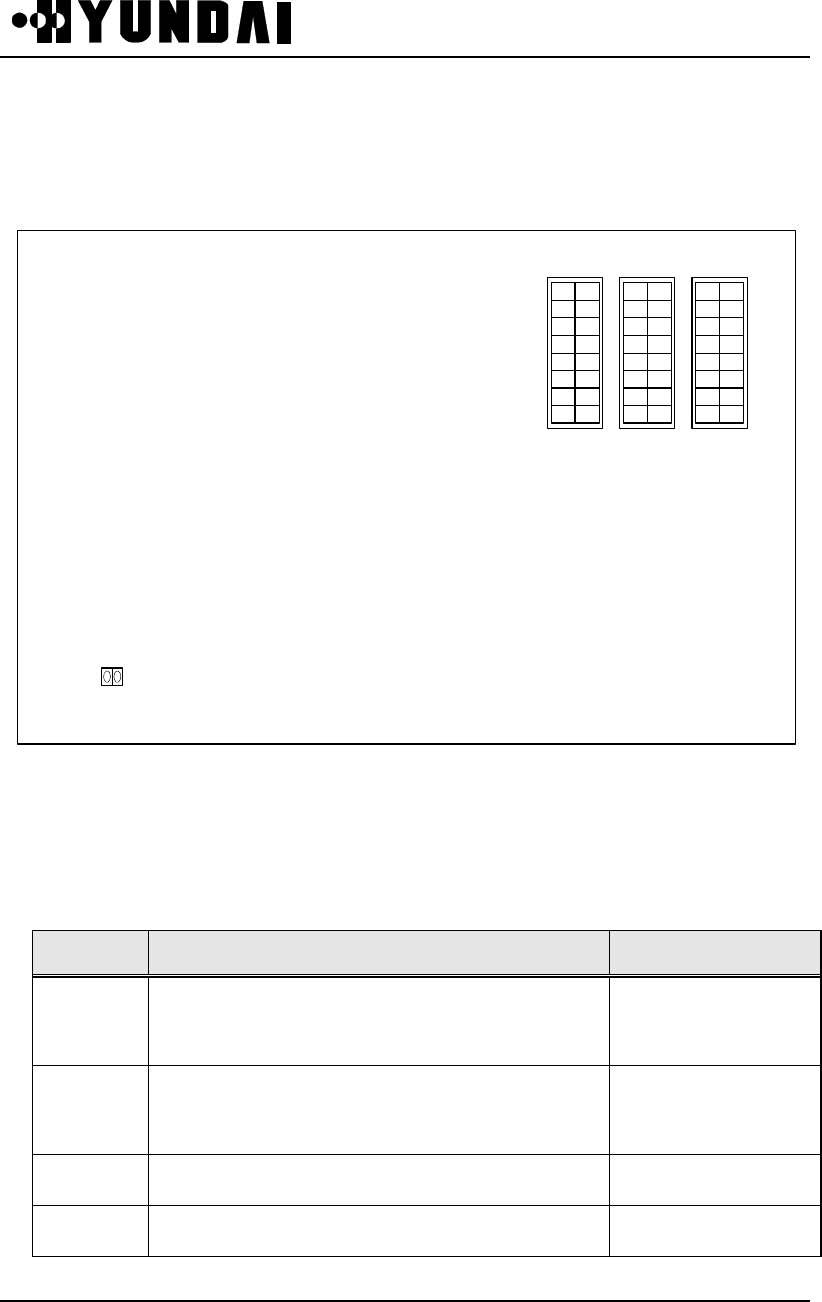
User’s Manual
PROPRIETARY & CONFIDENTIAL 4-24
4.2.14 CHBB-A1 (CIN HIPC Back Board-A1)
4.2.14.1 Mounting Drawing
J17J16
1 16
2 15
3 14
4 13
5 12
6 11
7 10
8 9
J15
1 16
2 15
3 14
4 13
5 12
6 11
7 10
8 9
1 16
2 15
3 14
4 13
5 12
6 11
7 10
8 9
J14
4.2.14.2 Setting
In LCIN A side, shunt J14 and In LCIN B side, open J14
No. Description Normal Config.
J14 open : SIDE1
shunt : SIDE0
J15 Upper 4 Bit : GCIN ID Setting (#0~#3)
Lower 4 Bit : LCIN ID Setting (#0~#11)
J16 Reserved (No Shunt)
J17 Reserved (No Shunt)

User’s Manual
PROPRIETARY & CONFIDENTIAL 4-25
4.2.14.2.1 Setting for LCIN
Address setting for LCIN is done on CHBB-A1.
CHBB-A1 Setting
l J14 strap : Classification of dualized LCIN Side (ON: Side 0, OFF: Side 1)
l J15 strap : LCIN ID Lower 4-BIT Setting, GCIN ID Upper 4-BIT Setting
l J16, J17 strap : Reserved
LCIN 0 LCIN 1 LCIN 2 LCIN 3 LCIN 4 LCIN 5 LCIN 6 LCIN 7 LCIN 8 LCIN 9 LCIN 10 LCIN 11
5-12 5-12 5-12 5-12 5-12 5-12 5-12 5-12 5-12 5-12 5-12 5-12
6-11 6-11 6-11 6-11 6-11 6-11 6-11 6-11 6-11 6-11 6-11 6-11
7-10 7-10 7-10 7-10 7-10 7-10 7-10 7-10 7-10 7-10 7-10 7-10
8-9 8-9 8-9 8-9 8-9 8-9 8-9 8-9 8-9 8-9 8-9 8-9
4.2.15 CCBB-A1 (CCP Back wiring Board-A1)
4.2.15.1 Mounting Drawing
JA4 JA2
JA1JA3
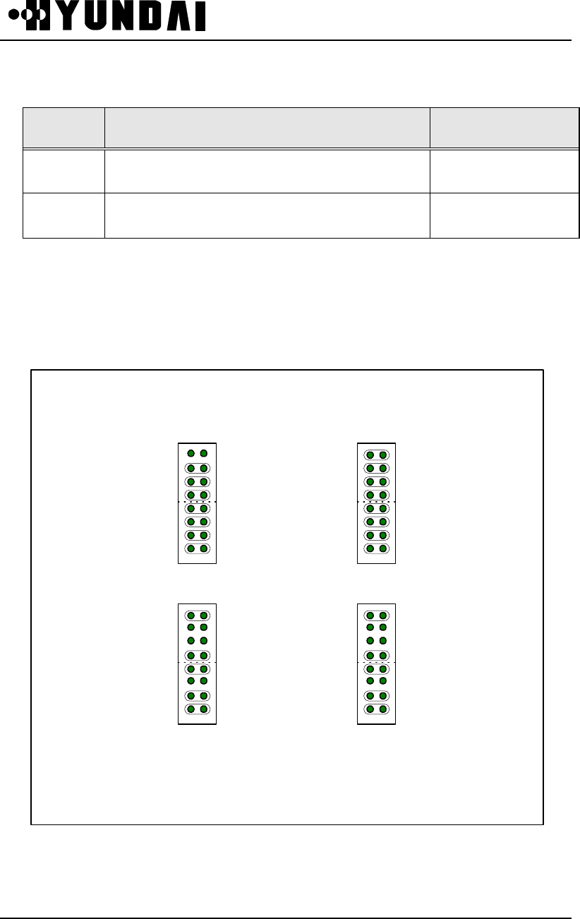
User’s Manual
PROPRIETARY & CONFIDENTIAL 4-26
4.2.15.2 Setting
No. Description Normal Config.
JA1/JA2 Strap for A side Address Setting of CCP-A1
JA3/JA4 Strap for B side Address Setting of CCP-A1
• JA1 - JA4 are currently used for CCP-A1 Address Setting.
Currently, CCP-A1 (0) has Physical Address 0064, 8064 and CCP-A1 (1) has
Physical Address 0165, 8165.
For example, Set Aside 0064, B side 8064 of CCP-A1 (0) as follows.
JA2
JA1JA3
JA4
CCP BSIDE CCP ASIDE
0
0
6
44
6
0
8

User’s Manual
PROPRIETARY & CONFIDENTIAL 4-27
4.2.16 ACPA-A1 (Alarm Control Processor Assembly-A1)
4.2.16.1 Mounting Drawing
JP3
JP2
JP1
4.2.16.2 Setting
When setting DS1232VCC Monitor, shunt JP1 in a normal operation is open.
When setting IPC Loop-back, shunt JP2 in a normal operation is open.
No. Description Normal Config.
JP1 1-2: DS1232VCC Monitor Enable
JP2 1-2 : IPC Loop-back ON
JP3 NOT USED

User’s Manual
PROPRIETARY & CONFIDENTIAL 4-28
4.2.17 SDBB-A1 (CKD Split & Distributed Back Board-A1)
4.2.17.1 Mounting Drawing
JP7
IA10
IA9
IA8
IA7
IA6
IA5
IA4
IA3
IA2
IA1
IA0
JP8
IB10
IB9
IB8
IB7
IB6
IB5
IB4
IB3
IB2
IB1
IB0
JP5JP6
IDAIDB
JP1
MS
JP2
MS
JP3
MS
JP4
MS
ID0A
ID1A
ID2A
ID3A
DI4A
ID0B
ID1B
ID2B
ID3B
DI4B

User’s Manual
PROPRIETARY & CONFIDENTIAL 4-29
4.2.17.2 Setting
No. Description Normal Config.
JP1
10MHz,1PPS Mode Setting
M : BSC 0 Shelf
S : BSC 1,2,3,4,5 Shelf
JP2
10MHz,1PPS Mode Setting
M : BSC 0 Shelf
S : BSC 1,2,3,4,5 Shelf
JP3
10MHz,1PPS Mode Setting
M : BSC 0 Shelf
S : BSC 1,2,3,4,5 Shelf
JP4
10MHz,1PPS Mode Setting
M : BSC 0 Shelf
S : BSC 1,2,3,4,5 Shelf
JP5
TFSA 0 Side ID Setting
ID0-2A : GCIN Classification
ID3A : BSC Classification
ID4A : SIDE Classification
JP6
TFSA 1 Side ID Setting
ID0-2B : GCIN Classification
ID3B : BSC Classification
ID4B : SIDE Classification
JP7
TSGA 0 Side ID Setting
IA0 : SIDE Classification
IA1-3 : CIN Classification
IA4-7 : BSC Classification
IA8-10 : RESERVED
ALL OFF-SET (OPEN) : “1”
JP8
TSGA 1 Side ID Setting
IB0 : SIDE Classification
IB1-3 : CIN Classification
IB4-7 : BSC Classification
IB8-10 : RESERVED
ALL SET : “0”
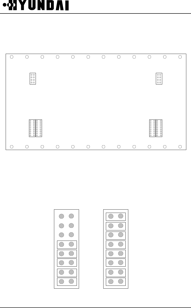
User’s Manual
PROPRIETARY & CONFIDENTIAL 4-30
4.2.18 TSBB-A1 (TSB Back Board-A1)
4.2.18.1 Mounting Drawing
CLKACLKB
A_ADDRHA_ADDRLB_ADDRLB_ADDRH
REAR SIDE
TSBB-A1
2
4
6
8
1
3
5
7
2
4
6
8
8
1
8
1
8
1
8
1
1
3
5
7
4.2.18.2 Setting
If Address of TSB0 is E000 (2byte address), set as follows. (If jumper is putting in, it
means “0” and if jumper is pulling out, it means “1”)
A_ADDRHA_ADDRH A_ADDRLA_ADDRL
E
0
0
0
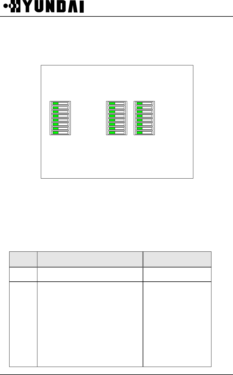
User’s Manual
PROPRIETARY & CONFIDENTIAL 4-31
4.2.19 BABB-A1 (BSC Alarm Back Board-A1)
4.2.19.1 Mounting Drawing
SW2 SW1SW3
4.2.19.2 Setting
When setting BSC ID “0”, SW2 (8~5) is ON and when setting BSC ID “1”, SW2
(8~5) is OFF. When setting GCIN ID “0”, SW1 (6~4) is ON and when setting GCIN
ID “1”, SW1 (6~4) is OFF.
No. Description Normal Config.
SW3 NOT USED
SW2
8 ON:BSC ID-BIT 3
7 ON:BSC ID-BIT 2
6 ON:BSC ID-BIT 1
5 ON:BSC ID-BIT 0
4 : OFF-1
3 : OFF-1
2 : OFF-1
1 : OFF-1
User’s Manual
PROPRIETARY & CONFIDENTIAL 4-32
No. Description Normal Config.
SW1
8 : OFF-1
7 : OFF-1
6 ON : GCIN ID BIT 2
5 ON : GCIN ID BIT 1
4 ON : GCIN ID BIT 0
3 : Reserved
2 : Reserved
1 ON : Side A
1 OFF : Side B
4.2.20 HSBB-A1 (HIPC Small Back Board-A1)
4.2.20.1 Mounting Drawing
1 16
2 15
3 14
4 13
5 12
6 11
7 10
8 9
J1
1 16
2 15
3 14
4 13
5 12
6 11
7 10
8 9
J2
1 16
2 15
3 14
4 13
5 12
6 11
7 10
8 9
J3
User’s Manual
PROPRIETARY & CONFIDENTIAL 4-33
4.2.20.2 Setting
No. Description Normal Config.
J1 Upper 4 Bit : GCIN ID Setting (#0~#3)
J2 Reserved (No Shunt)
J3 Reserved (No Shunt)
GCIN0 GCIN1 GCIN2 GCIN3
1 16 1 16 1 16 1 16
2 15 2 15 2 15 2 15
3 14 3 14 3 14 3 14
4 13 4 13 4 13 4 13

User’s Manual
PROPRIETARY & CONFIDENTIAL 4-34
4.3 LED Description
PBA Front Panel LED Normal Abnormal Description
RUN ON OFF Drives with Run signal of CPU and ON if normal operation
FAIL OFF ON ON when in the state of unable to recover, or indicating
PBA Fail
ACT ON OFF ON when Active, OFF when Standby
CHS OFF/ON ON when U-Link A channel enable
CIFA-A1
¡ RUN
¡ FAIL
¡ ACT
¡ CHS
¡ CHX
CHX ON/ OFF ON when U-Link B channel enable
RUN ON OFF OFF when CPU Error (Change PBA)
OVWR ON OFF ON state indicating of overwriting data from Active Side to
Standby Side in connection with D-Channel
FAIL OFF ON
Indicating PBA Fail (After Reset, abnormal state exists) or
ON when in the state of local resource initial during
Processor Loading
ACT ON,OFF ON when Active, OFF when Standby
CONF OFF ON ON when C-CH Error occurs or Reset, default is OFF
CMSG ON,OFF In the state of transmission of Message to C-CH. default is
OFF.
MCDA
¡ RUN
¡ OVWR
¡ FAIL
¡ ACT
¡ CONF
¡ CMSG
¡ HALT
HALT OFF ON ON when CPU Halt due to critical error.
(Reset with CPU Halt or PBA change if necessary)

User’s Manual
PROPRIETARY & CONFIDENTIAL 4-35
PBA Front Panel LED Normal Abnormal Description
ACT ON,OFF ON when operates as an Active (After Reset, abnormal
state exists, then Change PBA)
RUN ON OFF ON when CPU normal operation, OFF when abnormal
FAIL OFF ON Indicating PBA Fail (After Reset, abnormal state exists, then
Change PBA)
HICA-A2
¡ ACT
¡ RUN
¡ FAIL
¡ CLKF
CLKF OFF ON when reference clock of Link is abnormal
RUN ON OFF ON (Green) when CPU operates
FAIL OFF ON ON (Red) when PBA function is abnormal,
/ After Reset, Change PBA if Led is ON
ROUTE - - ON (Green) when Packet transmit/receive with Trunk
TEST - - when performs PBA test function ON (Yellow)
LER0 OFF ON
LER1 OFF ON
LER2 OFF ON
LER3 OFF ON
LER4 OFF ON
LER5 OFF ON
LER6 OFF ON
HNTA-A2
¡ RUN
¡ FAIL
¡ ROUTE
¡ TEST
¡ LER0
¡ LER1
¡ LER2
¡ LER3
¡ LER4
¡ LER5
¡ LER6
¡ LER7
LER7 OFF ON
Indicating abnormal status of 8 Trunks.
: ON when Trunk is Cutting Off.
(Check the connection status of connector and if ON
continually, after checking Trunk status with instrument,
PBA Change if ON continually)

User’s Manual
PROPRIETARY & CONFIDENTIAL 4-36
PBA Front Panel LED Normal Abnormal Description
RUN ON OFF ON when CPU operates normally
FAIL OFF ON ON when Reset and HRNA-A2 fails
ROUTE - - ON when transmit packet frame using D-BUS and U-
LINK
TEST - - ON when PBA performs test function
ACT1 - - ON when NODE 1 is ACTIVE
ACT2 - - ON when NODE 2 is ACTIVE
ACT3 - - ON when NODE 3 is ACTIVE
ACT4 - - ON when NODE 4 is ACTIVE
ACT5 - - ON when NODE 5 is ACTIVE
ACT6 - - ON when NODE 6 is ACTIVE
ACT7 - - ON when NODE 7 is ACTIVE
HRNA-A2
¡ RUN
¡ FAIL
¡ ROUTE
¡TEST
¡ ACT1
¡ ACT2
¡ ACT3
¡ ACT4
¡ ACT5
¡ ACT6
¡ ACT7
¡ ACT8
ACT8 - - ON when NODE 8 is ACTIVE

User’s Manual
PROPRIETARY & CONFIDENTIAL 4-37
PBA Front Panel LED Normal Abnormal Description
RUN ON OFF CPU Status
ACT ON OFF ACTIVE Status
1PPS Blink OFF 1PPS input status
10M ON OFF 10MHz input status
TFSA-A1
RUN
ACT
1PPS
10M
TOD
TOD Blink OFF TOD input status
ACT Blink ON Blink when Active, Off when Standby, ON when
abnormal status
RUN ON OFF CPU Status
10M Blink OFF 10MHz input status
1PPS Blink OFF 1PPS input status
PLL ON OFF Internal PLL LOCKING Status
TSGA-A1
ACT
RUN
10M
1PPS
PLL
50Hz
50HZ ON OFF 50Hz CLOCK Status
ACT Blink ON Blink when Active, Off when Standby, ON when
abnormal status
TFDA-A1
ACT
PWR PWR ON OFF POWER Status

User’s Manual
PROPRIETARY & CONFIDENTIAL 4-38
PBA Front Panel LED Normal Abnormal Description
RUN ON (Green) ON if CPU is active and operates normally.
FAIL OFF ON (Red) LED is controlled by S/W, OFF when started
OS, ON when not started OS.
HALT OFF ON (Red) ON when CPU halt and both fail of two links
due to significant error.
CLKF OFF ON (Yellow) ON when clock is abnormal from CKD Block
ROUTE ON (Green) ON when packet is moving.
LINKA OFF Unused.
VSIA-C1
¡ RUN
¡ FAIL
¡ HALT
¡ CLKALM
¡ ROUTE
¡ LINKA
¡ LINKB
LINKB OFF Unused
ACPA-A1
¡ RUN
¡ FAIL
¡ HALT
RUN
FAIL
HALT
ON (Green)
OFF
OFF
ON (Red)
ON (Red)
ON (Red)
Board is in the state of operating.
ON if not finished of Down Loading
ON when system is in the state of abnormal.
GTFU-A1
¡ RUN
¡ ACT
¡ GPSALM
¡ 1PPSALM
¡ FAULT
RUN
ACT
GPSALM
1PPSALM
FAULT
ON
ON(A)/OFF(S)
OFF
OFF
OFF
OFF
-
ON
ON
ON
Normal Operational Status
Provide 10MHz,1PPS Output To System
Tracking GPS Satellite
1PPS Exceed Over 800nsec
System Fault Condition

User’s Manual
PROPRIETARY & CONFIDENTIAL 4-39
PBA Front Panel LED Normal Abnormal Description
50MHZ ON (Green) OFF ON when clock is normal from CKD BLOCK
RUN A/B ON (Green) OFF ON when A/B Side CPU operates normally
FAIL A/B OFF ON (Red) ON before Down Loading from CCP Block, OFF
if ended
DSP 0/6 ON (Yellow)/OFF Blink DSP 0/6 ON When call setup, OFF when
release, Blink when DSP is abnormal.
DSP 1/7 ON (Green)/OFF Blink DSP 1/7 ON When call setup, OFF when
release, Blink when DSP is abnormal.
DSP 2/8 ON (Green)/OFF Blink DSP 2/8 ON When call setup, OFF when
release, Blink when DSP is abnormal.
DSP 3/9 ON (Green)/OFF Blink DSP 3/9 ON When call setup, OFF when
release, Blink when DSP is abnormal.
DSP 4/10 ON (Green)/OFF Blink DSP 4/10 ON When call setup, OFF when
release, Blink when DSP is abnormal.
VSOA-A1
¡ ¡ 50MHZ
¡ ¡ RUN A/B
¡ ¡ FAIL A/B
¡ ¡ DSP 0/6
¡ ¡ DSP 1/7
¡ ¡ DSP 2/8
¡ ¡ DSP 3/9
¡ ¡ DSP 4/10
¡ ¡ DSP 5/11
DSP 5/11 ON (Green)/OFF Blink DSP 5/11 ON When call setup, OFF when
release, Blink when DSP is abnormal.

User’s Manual
PROPRIETARY & CONFIDENTIAL 4-40
4.4 COMMAND LIST
COD_ID Description Command Parameter
C5668 Equip Activate of ACP ACT-ACP :BSC=a, ACP=b;
C5610 Equip Activate of AMP ACT-AMP :{BSC=a, BCP=b}/{BTS=a}, SECT=c, FA=d;
C5605 Equip Activate of BTS Link ACT-BLNK :{BSC=a, BCP=b}/{BTS=a}, BCP=b, LINK=c;
C5600 Equip Activate of BTS ACT-BTS :{BSC=a, BCP=b}/{BTS=a};
C5662 Equip Activate of BTU ACT-BTU :{BSC=a, BCP=b}/{BTS=a};
C5686 Equip Activate of CCC ACT-CCC :{BSC=a, BCP=b}/{BTS=a}, DU=c, SLOT=d;
C2014 CCP Old/New PKG Change
Activate ACT-CCP-SBY :BSC=a;
C5685 Equip Activate of Channel
Element ACT-CE :{BSC=a, BCP=b}/{BTS=a}, DU=c, SLOT=d, SNODE=e;
C5663 Equip Activate of GCIN
HRNA ACT-GCIN :HRNA=a;
C5667 Equip Activate of BIN HNEA ACT-HNEA-BIN :{BSC=a, BCP=b}/{BTS=a},HNEA=c;
C5666 Equip Activate of LCIN
HNEA ACT-HNEA-LCIN :BSC=a,HNEA=b;
C5665 Equip Activate of BIN HRNA ACT-HRNA-BIN :{BSC=a, BCP=b}/{BTS=a},HRNA=c;
C5664 Equip Activate of LCIN
HRNA ACT-HRNA-LCIN :BSC=a,HRNA=b;
C9010 Equip Activate of LINK ACT-LINK :BSC=a,LINK=b;
COD_ID Description Command Parameter

User’s Manual
PROPRIETARY & CONFIDENTIAL 4-41
C9009 Equip Activate of Link Set ACT-LSET :BSC=a;
C3003 Overload Threshold Activate ACT-OVLD-THR :{PRC=a, BSC=b}/{PRC=a,BSC=b,BCP=c}/{BTS=a}, ONOFF=d;
C5637 Equip Activate of SIP ACT-SIP :BSC=a, SIP=b;
C5639 Equip Activate of SVE ACT-SVE :BSC=a, SIP=b, SVP=c, SVE=d;
C5638 SVP of Equip Activate ACT-SVP :BSC=a, SIP=b, SVP=c;
C2007 Add Loading Block ADD-LDNG-BLK
:{BSC=a}/{BSC=a, BLKTYPE=b}, HDTYPE=c, BLKNAME=d,
VERSION=e;
C5242 Add BTS NEBR ADD-NEBR :{BSC=a, BCP=b}/{BTS=a}, SECT=c, FA=d, NBRBTS=e, NBRSECT=f;
C4501 Add Mobile MARKOV
function ADD-REG-MARK :MIN=a,SCM=b,BTS=c,RATE=d;
C1000 Allow alarm message output ALW-ALM-MSG :AN=a;
C1020 Allow reflection of alarm
status ALW-ALM-STS
C1001 Allow audio alarm output ALW-AUD-ALM [ :GRD=a];
C6404 Allow daily statistics ALW-DRPT-MSG :BSC=a;
C1002 Allow fault message output ALW-FLT-MSG :FN=a;
C6403 Allow hourly statistics ALW-HRPT-MSG :BSC=a;
C6405 Allow monthly statistics ALW-MRPT-MSG :BSC=a;
C4401 Allow periodic diagnostic ALW-PED-TST :DEV=a,{BSC=b, BCP=c}/{BTS=b}/{BSC=b, SIP=c};
COD_ID Description Command Parameter
C3503 Allow status message output ALW-STS-MSG :CODE=a;

User’s Manual
PROPRIETARY & CONFIDENTIAL 4-42
C4301 Allow device test ALW-TST :DEV=a, MODE=b {,BSC=c};
C9018 Correct of alarm status AUDIT-ALARM
C5410 Block AMP BLK-AMP :{BSC=a, BCP=b}/{BTS=a}, SECT=c, FA=d;
C5405 Block BTS Link BLK-BLNK :{BSC=a, BCP=b}/{BTS=a}, LINK=c;
C5400 Block BTS BLK-BTS :{BSC=a, BCP=b}/{BTS=a};
C5486 Block CCC BLK-CCC :{BSC=a, BCP=b}/{BTS=a}, DU=c, SLOT=d;
C5485 Block Channel Element BLK-CE :{BSC=a, BCP=b}/{BTS=a}, DU=c, SLOT=d, SNODE=e;
C5437 Block SIP BLK-SIP :BSC=a, SIP=b;
C5439 Block SVE BLK-SVE :BSC=a, SIP=b, SVP=c, SVE=d;
C5438 Block SVP BLK-SVP :BSC=a, SIP=b, SVP=c;
C5116 Change Access Channel
Parameter value CHG-AC-PARA :{BSC=a, BCP=b}/{BTS=a}, FA=c, SECT=d [,Param];
C5119 Change Access Channel
message CHG-ACC-MSG :{BSC=a, BCP=b}/{BTS=a}, FA=c, SECT=d [,Param];
C1023 Change BCP Alarm CHG-ALM-BCP :{BSC=a[,BCP=b]},REG=c,BIT=d,ALM_CODE=e,DEV=f,SECT=g,CDM
A=h,
EQUIP=i;
C3113 Change BCP Device Control CHG-BCP-CTRL :CTRL=a{,BSC=b,BCP=c}/{,BTS=b},BLNKCTRL=d,CEDYNCTRL=e,C
DMACHDYNCTRL=f,FAILTIME=g;
COD_ID Description Command Parameter

User’s Manual
PROPRIETARY & CONFIDENTIAL 4-43
C4704 Change HICA BER CHG-BER-HICA :LINKTYPE=a,BERTHR=b,SYNCTHR=c,SLIPTHR=d,CRCBPLRTHR=e;
C4703 Change BER Diagnostic CHG-BER-TST :{BSC=a,BCP=b}/{BTS=a},AUTOFLAG=c,TERM=d,THRESHOLD=e;
C5105 Change BLINK
Configuration CHG-BLNK-CONF :{BSC=a, BCP=b}/{BTS=a}, LINK=c[,USRPOFF];
C3509 Change BLINK Error
Parameter CHG-BLNK-ERR :TYPE=a, {BSC=b,BCP=c}/{BTS=b}, WINSIZE=d, FREERATE=e;
C5134 Change BSC Configuration
Information CHG-BSC-CONF :BSC=a [, PARAM];
C5100 Change BTS Configuration
Information CHG-BTS-CONF :{BSC=a, BCP=b}/{BTS=a} [,Param];
C5112 Change CDMA Channel
Configuration CHG-CDMA-CONF :{BSC=a, BCP=b}/{BTS=a}, FA=c [,Param];
C5102 Change CDMA Information CHG-CDMA-INFO :FA=a, CHNUM=b;
C5114 Change Channel Element
Type CHG-CE-TYPE
:{BSC=a, BCP=b}/{BTS=a}, DU=c, SLOT=d, SNODE=e, TYPE=f
[,Param];
C5132 Change Forward Link Power
Control Data Set1 CHG-FPC1-INFO :{BSC=a, BCP=b}/{BTS=a}, FA=c, SECT=d [,Param];
C5144 Change Forward Link Power
Control Data Set2 CHG-FPC2-INFO :{BSC=a, BCP=b}/{BTS=a}, FA=c, SECT=d [,Param];
COD_ID Description Command Parameter

User’s Manual
PROPRIETARY & CONFIDENTIAL 4-44
C5113 Change Forward Link Power
Data Value CHG-FWDP-INFO :{BSC=a, BCP=b}/{BTS=a}, FA=c, SECT=d [,Param];
C5142 Change NEBR Priority CHG-NEBR-PRI :{BSC=a, BCP=b}/{BTS=a}, SECT=c, FA=d, INDEX=e [,Param];
C9015 Change OPC Information CHG-OPC :BSC=a [, OPC=b][, MAXLNK=c];
C3304 Change Overload Threshold
Value CHG-OVLD-THR :{BSC=a, BCP=b}/{BTS=a}, DEV=c, CRI=d, MAJ=e, MIN=f, ONSET=g;
C5118 Change Paging Channel
Parameter CHG-PC-PARA :{BSC=a, BCP=b}/{BTS=a}, FA=c, SECT=d [, PC=e], PCGAIN=f;
C4403 Change Period TEST CHG-PED-TST :DEV=a, {BSC=b, BCP=c}/{BTS=b},DEVID=d,STIM=e,ETIM=f,CNT=g;
C5117 Change Pilot/Sync Channel
Parameter CHG-PSC-PARA :{BSC=a, BCP=b}/{BTS=a}, FA=c, SECT=d [,Param];
C4503 Change Mobile MARKOV
Register CHG-REG-MARK :MIN=a,SCM=b,BTS=c,RATE=d;
C5120 Change RF Control Card
Information CHG-RFC-PARA :{BSC=a, BCP=b}/{BTS=a}, FA=c, SECT=d [,Param];
C5133 Change Reverse Link Power
Control Data Value CHG-RPC-INFO :{BSC=a, BCP=b}/{BTS=a}, FA=c, SECT=d [,Param];
C5104 Change Sub Cell Data Value CHG-SCEL-INFO :{BSC=a, BCP=b}/{BTS=a}, FA=c, SECT=d [,Param];
C5101 Change Sector Information
Data Value CHG-SECT-INFO :{BSC=a, BCP=b}/{BTS=a}, SECT=c [,Param];
C5106 Change System DATA CHG-SYS-PARA :{BSC=a, BCP=b}/{BTS=a}, FA=c, SECT=d [,Param];
COD_ID Description Command Parameter

User’s Manual
PROPRIETARY & CONFIDENTIAL 4-45
C5115 Change Traffic Channel
Parameter CHG-TC-PARA :{BSC=a, BCP=b}/{BTS=a}, FA=c [,Param];
C4303 Change Automatic Test
Information CHG-TST :DEV=a, BSC=b, TERM=c, CNT=d;
C1018 Check BSC Alarm CHK-BSC-ALM :BSC=a;
C1017 Check BTS Alarm CHK-BTS-ALM :{BSC=a, BCP=b}/{BTS=a};
C1003 Clear Audio Alarm CLR-AUD-ALM
C5731 Deactivate ACP DACT-ACP :BSC=a, ACP=b;
C5710 Deactivate AMP DACT-AMP :{BSC=a, BCP=b}/{BTS=a},SECT=c,FA=d;
C5705 Deactivate BTS Link DACT-BLNK :{BSC=a, BCP=b}/{BTS=a}, LINK=c;
C5700 Deactivate BTS DACT-BTS :{BSC=a, BCP=b}/{BTS=a};
C5762 Deactivate BTU DACT-BTU :{BSC=a, BCP=b}/{BTS=a};
C5786 Deactivate CCC DACT-CCC :{BSC=a, BCP=b}/{BTS=a}, DU=c, SLOT=d;
C5785 Deactivate Channel Element DACT-CE :{BSC=a, BCP=b}/{BTS=a}, DU=c, SLOT=d, SNODE=e;
C5763 Deactivate GCIN HRNA DACT-GCIN :HRNA=a;
C5767 Deactivate BIN HNEA DAC-HNEA-BIN :{BSC=a, BCP=b}/{BTS=a},HNEA=c;
C5766 Deactivate LCIN HNEA DACT-HNEA-LCIN :BSC=a,HNEA=b;
C5765 Deactivate BIN HRNA DACT-HRNA-BIN :{BSC=a, BCP=b}/{BTS=a},HRNA=c;
COD_ID Description Command Parameter
C5764 Deactivate LCIN HRNA DACT-HRNA-LCIN :BSC=a, HRNA=b;

User’s Manual
PROPRIETARY & CONFIDENTIAL 4-46
C9012 Deactivate Link DACT-LINK :BSC=a, LINK=b;
C5735 Deactivate Link Set DACT-LSET :BSC=a;
C5737 Deactivate SIP DACT-SIP :BSC=a, SIP=b;
C5739 Deactivate SVE DACT-SVE :BSC=a, SIP=b, SVP=c, SVE=d;
C5738 Deactivate SVP DACT-SVP :BSC=a, SIP=b, SVP=c;
C9003 Define DPC DEF-DPC :BSC=a, DPC=b;
C9005 Define Link DEF-LINK :BSC=a, LINK=b, ACTIND=c, TSTSLC=d;
C9004 Define Link Set DEF-LSET :BSC=a, LSHAR=b, ACTIND=c;
C9016 Define SCCP DEF-SCCP :BSC=a, SYSID=b, SSN=c;
C9006 Delete DPC DEL-DPC :BSC=a;
C2008 Delete Loading Block DEL-LDNG-BLK :BSC=a [, BLKTYPE=b], BLKNAME=c;
C9008 Delete Link DEL-LINK :BSC=a, LINK=b;
C9007 Delete Link Set DEL-LSET :BSC=a;
C4502 Delete Mobile MARKOV
Register DEL-REG-MARK :MIN=a;
C9017 Delete SCCP DEL-SCCP :BSC=a;
COD_ID Description Command Parameter
C5016 Confirm Access Channel
Parameter DIS-AC-PARA :{BSC=a, BCP=b}/{BTS=a}, FA=c, SECT=d, PC=e;

User’s Manual
PROPRIETARY & CONFIDENTIAL 4-47
C5019 Output ACC Message DIS-ACC-MSG :{BSC=a, BCP=b}/{BTS=a}, FA=c, SECT=d;
C5068 Output ACP Configuration
Information DIS-ACP-CONF :BSC=a;
C4508 Output Active MARKOV Call DIS-ACT-MARK
C1014 Output ACP Alarm DIS-ALM-ACP [ :BSC=a [, ACP=b [, SRC=c]]];
C1022 Output BCP Alarm DIS-ALM-BCP :{BSC=a [, BCP=b]}/{BTS=c};
C1006 Output Alarm Information DIS-ALM-INFO
N :AN=a;
C1004 Output Current Alarm Status DIS-ALM-STS {[ :BSC=a [, BCP=b]]}/{[BTS=a]}[,DETAIL=c];
C5010 Output AMP Configuration
Information DIS-AMP-CONF {BSC=a, BCP=b}/{BTS=a}, SECT=c;
C1005 Output Audio Alarm DIS-AUD-ALM
C4512 Output BCP Call Number DIS-BCP-CALL :{BSC=a, BCP=b}/{BTS=a},FA=c;
C3109 Output BCP Device CTRL DIS-BCP-CTRL :{BSC=a, BCP=b}/{BTS=a};
C4702 Output BER Information DIS-BER-INFO :PROC=a,BSC=b;
C3208 Output BIN HNEA Status DIS-BIN-HLEA :{BSC=a, BCP=b}/{BTS=a};
C3206 Output BIN Node Status DIS-BIN-NODE :{BSC=a, BCP=b}/{BTS=a};
C3203 Output BIN Processor Status DIS-BIN-PRC :{BSC=a, BCP=b}/{BTS=a};
COD_ID Description Command Parameter
C2004 Output Block Loading History
Function DIS-BLLD-HIS
:{BSC=a, PROC=b [,{ACP=c}/{SIP =c, SVP=d}/{BCP=c}]}/{BTS=a,
PROC=b [, DU=c [,CCC=d]]}, BLKNAME=e;
C5005 Output BLINK Configuration DIS-BLNK-CONF :{BSC=a, BCP=b}/{BTS=a};

User’s Manual
PROPRIETARY & CONFIDENTIAL 4-48
C3508 Output BLINK Error Parameter DIS-BLNK-ERR :{BSC=a, BCP=b}/{BTS=a};
C3004 Output BLINK Status DIS-BLNK-STS :{BSC=a, BCP=b}/{BTS=a};
C3401 Output BSC ACP Information DIS-BSC-ACP :BSC=a;
C5034 Output BSC Configuration
Information DIS-BSC-CONF
C5081 BSC Information Output DIS-BSC-INFO
C3102 BTS Card Status Output DIS-BTS-CARD :{BSC=a, BCP=b}/{BTS=a}, CARD=c;
C5000 Confirm BTS Configuration
Information DIS-BTS-CONF :{BSC=a, BCP=b}/{BTS=a};
C5082 Confirm & Output BTS
Operation Information DIS-BTS-INFO :{BSC=a, BCP=b}/{BTS=a};
C3101 Output BCP Processor Status DIS-BTS-PRC :{BSC=a [, BCP=b]}/{BTS=a};
C3402 Output BTS SACA Status DIS-BTS-SACA :{BSC=a [, BCP=b]}/{BTS=a};
C5062 Output BTU Configuration DIS-BTU-CONF :{BSC=a, BCP=b}/{BTS=a};
C3307 Output Call Number DIS-CALL-STS :PROC=a, {BSC=b, BCP=c}/{BTS=b};
COD_ID Description Command Parameter
C3103 Output CC Status DIS-CC-STS :{BSC=a, BCP=b}/{BTS=a};
C3001 Output CCP Status DIS-CCP-STS [ :BSC=a];
C2017 Output CCP Version DIS-CCP-VER :BSC=bsc, SIDE=b;

User’s Manual
PROPRIETARY & CONFIDENTIAL 4-49
C5012 Confirm CDMA Configuration
Information DIS-CDMA-CONF :{BSC=a, BCP=b}/{BTS=a};
C5002 Confirm CDMA Channel
Information DIS-CDMA-INFO
C3108 Output CDMA Channel
Information
DIS-CDMACH-LIST
:{BSC=a, BCP=b}/{BTS=a};
C3106 Output CE Status DIS-CE-STS :{BSC=a, BCP=b}/{BTS=a},DU=c;
C5090 Output CDMA Channel List
Message DIS-CHLIST-MSG :{BSC=a, BCP=b}/{BTS=a},SECT=c;
C0001 Output Command History DIS-CMD-HIS :DATE=a, STIME=b, ETIME=c, TYPE=d, CODE=e;
C9000 Output CSB Configuration
Information DIS-CSB-INFO [ :BSC=a];
C9019 Output CSB Status DIS-CSB-STS [ :BSC=a];
C4509 Output Deactivated MARKOV
Call DIS-DACT-MARK
C6017 Output statistic data Collection
Status DIS-DATA-COLL
COD_ID Description Command Parameter
C5014 Output DU Configuration
Information DIS-DU-CONF :{BSC=a, BCP=b}/{BTS=a}, SHELF=c [, SLOT=d];
C5089 Output Extended System
Parameter
DIS-EXTSYS-MSG
:{BSC=a, BCP=b}/{BTS=a}, SECT=c, FA=d;

User’s Manual
PROPRIETARY & CONFIDENTIAL 4-50
C1021 Output Fault Information DIS-FLT-INFO :FN=a;
C5032 Confirm BTS Forward Link
Power Control Value DIS-FPC1-INFO :{BSC=a, BCP=b}/{BTS=a}, FA=c, SECT=d;
C5044 Confirm BTS Forward Link
Power Control Value DIS-FPC2-INFO :{BSC=a, BCP=b}/{BTS=a}, FA=c, SECT=d;
C5013 Confirm Subcell Forward Link
Power Value DIS-FWDP-INFO :{BSC=a, BCP=b}/{BTS=a}, FA=c, SECT=d;
C5063 Output GCIN Configuration DIS-GCIN-CONF
C3204 Output GCIN Node Status
DIS-GCIN-NODE
C3201 Output GCIN Processor
Status DIS-GCIN-PRC
C3403 Output GPS Status DIS-GPS-STS
C3209 Output GW Node Status DIS-GW-NODE :NODETYPE=a,{BSC=b, BCP=c}/{BTS=b}
C5067 Output BIN HNEA Status DIS-HNEA-BIN {BSC=a, BCP=b}/{BTS=a};
C5066 Output LCIN HNEA Status DIS-HNEA-LCIN :BSC=a;
C5065 Output BIN HRNA Status DIS-HRNA-BIN :{BSC=a, BCP=b}/{BTS=a};
COD_ID Description Command Parameter
C5064 Output LCIN HRNA Status DIS-HRNA-LCIN :BSC=a;
C1007 Supply Output-Inhibited alarm
information DIS-INH-ALM
C1008 Supply Output-inhibited Fault
Information DIS-INH-FLT
;

User’s Manual
PROPRIETARY & CONFIDENTIAL 4-51
C6003 Output Output-inhibited Fault
Statistics List DIS-INH-MSG
C3502 Output Output-inhibited
Status Messages List DIS-INH-STS
C3207 Output LCIN HNEA Node
Information DIS-LCIN-HNEA :BSC=a;
C3205 Output LCIN Node Status DIS-LCIN-NODE :BSC=a;
C3202 Output LCIN Processor
Status DIS-LCIN-PRC :BSC=a;
C2003 Loading Table Output
Function DIS-LDNG-TBL :BSC=a, PROC=b;
C9001 Output Link Information DIS-LINK-INFO :BSC=a, LINK=b;
C5036 Confirm MSC Link Channel
Configuration Information DIS-MCH-CONF :BSC=a, LINK=b;
C5035 Output MSC Link
Configuration Information DIS-MLNK-CONF :BSC=a;
COD_ID Description Command Parameter
C3005 MSC Link Status Output DIS-MLNK-STS :BSC=a, LINK=b;
C0002 Output Message History DIS-MSG-HIS :DATE=a, STIME=b, ETIME=c, TYPE=d, CODE=e;
C5042 Confirm BTS Neighbor List DIS-NEBR-INFO :{BSC=a, BCP=b}/{BTS=a}, SECT=c, FA=d;
C3306 Output Out Of Service Status DIS-OOS-STS :DEV=a, TYPE=b;
C3301 Output CPU Overload Status DIS-OVLD-STS :PRC=a, {BSC=b [,BCP=c]}/{BTS=b};

User’s Manual
PROPRIETARY & CONFIDENTIAL 4-52
C3302 Output CPU Overload Limit DIS-OVLD-THR :PRC=a, {BSC=b [,BCP=c]}/{BTS=b};
C5018 Confirm Paging Channel
Parameter DIS-PC-PARA :{BSC=a, BCP=b}/{BTS=a}, FA=c, SECT=d, PC=e;
C4003 Output periodic Test
Information DIS-PED-INFO :DEV=a, BSC=b;
C5883 Output PLD Information DIS-PLD-INFO [ :BSC=a];
C5031 Output PN Cell Information DIS-PN-CELL [ :PILOT=a];
C2005 Processor Loading History
Function DIS-PRLD-HIS
:{BSC=a, PROC=b [, {ACP=c}/{SIP=c[,SVP=d]}/{BCP=c}]}/{BTS=a,
PROC=b [,DU=c [,CCC=d]]};
C5017 Confirm Pilot/Sync Channel
Parameter DIS-PSC-PARA :{BSC=a, BCP=b}/{BTS=a}, FA=c, SECT=d;
C4507 Confirm Mobile MARKOV
Register DIS-REG-MARK
C5020 Output RFC Parameter
Function DIS-RFC-PARA :{BSC=a, BCP=b}/{BTS=a}, FA=c, SECT=d;
COD_ID Description Command Parameter
C5033 Confirm BTS Reverse Link
Power Control Value DIS-RPC-INFO :{BSC=a, BCP=b}/{BTS=a}, FA=c, SECT=d;
C4002 Output Reverse Link Test
Information DIS-RSV-INFO :DEV=a, BSC=b;
C9002 Output SCCP Information DIS-SCCP-INFO [ :BSC=a];
C5004 Confirm Subcell Data Value DIS-SCEL-INFO :{BSC=a, BCP=b}/{BTS=a}, SECT=c, FA=d;
C5001 Confirm Sector Information DIS-SECT-INFO :{BSC=a, BCP=b}/{BTS=a}, SECT=c;

User’s Manual
PROPRIETARY & CONFIDENTIAL 4-53
C5004 Confirm Subcell Data Value DIS-SCEL-INFO :{BSC=a, BCP=b}/{BTS=a}, CFID=c, SECT=d;
C5003 Confirm Subcell Key DIS-SCEL-KEY {BSC=a, BCP=b}/{BTS=a},SECT=c,CFID=d;
C5001 Confirm Sector Information DIS-SECT-INFO :{BSC=a, BCP=b}/{BTS=a}, SECT=c;
C5037 Confirm & Output SIP
Configuration DIS-SIP-CONF :BSC=a;
C3002 Output SIP Status DIS-SIP-STS :BSC=a [,SIP=b];
C6000 Output List about statistic
item DIS-STAT-ITEM
C6001 Output Activated Statistic
Item DIS-STAT-JOB [ :BSC=a];
C3501 Confirm Status Information DIS-STS-INFO [ :CODE=a];
C5039 Confirm & Output of SVE
Configuration in SVP DIS-SVE-CONF :BSC=a, SIP=b, SVP=c;
COD_ID Description Command Parameter
C3004 Output Vocoder Status DIS-SVE-STS :BSC=a, SIP=b [, SVP=c];
C5038 Confirm & Output SVP
Configuration in SIP DIS-SVP-CONF :BSC=a, SIP=b;
C3003 Output SVP Status DIS-SVP-STS :BSC=a [, SIP=b];
C5087 Output Sync-Channel
Message DIS-SYNC-MSG :{BSC=a, BCP=b}/{BTS=a}[, SECT=c][, FA=d];
C5006 Confirm BTS System
Parameter DIS-SYS-PARA :{BSC=a, BCP=b}/{BTS=a}[, SECT=c][, FA=d];

User’s Manual
PROPRIETARY & CONFIDENTIAL 4-54
C5884 Confirm System Version DIS-SYS-VER :BSC=a;
C5088 Output System parameter
Message
DIS-SYSPARA-MSG
:{BSC=a, BCP=b}/{BTS=a}[, SECT=c][, FA=d];
C5015 Confirm Traffic Channel
Parameter DIS-TC-PARA :{BSC=a, BCP=b}/{BTS=a}, FA=c;
C3105 Output TCE Status DIS-TCE-STS :{BSC=a, BCP=b}/{BTS=a}, DU=c;
C3404 Confirm TSGA Status DIS-TSGA-STS :BSC=a;
C4001 Confirm Test Information DIS-TST-INFO :BSC=c;
C2016 Run CCP New PKG DRV-CCP-SBY :BSC=a;
C1009 Inhibit Alarm Message output INH-ALM-MSG :AN=a;
C1019 Inhibit Alarm Status output INH-ALM-STS
C1010 Inhibit Audible Alarm INH-AUD-ALM [ :GRD=a];
COD_ID Description Command Parameter
C6304 Inhibit daily Statistics output INH-DRPT-MSG :BSC=a;
C1011 Inhibit Fault Message output INH-FLT-MSG :FN=a;
C6303 Inhibit hourly statistics output INH-HRPT-MSG :BSC=a;
C9013 Inhibit use of LINK INH-LINK :BSC=a, LINK=b;
C6305 Inhibit monthly statistics
output INH-MRPT-MSG :BSC=a;
C4402 Inhibit periodic diagnostic INH-PED-TST :DEV=a,{BSC=b, BCP=c}/{BTS=b}/{BSC=a, SIP=b};

User’s Manual
PROPRIETARY & CONFIDENTIAL 4-55
C3504 Inhibit Status Message
Output INH-STS-MSG :CODE=a;
C4302 Inhibit automatic test INH-TST :DEV=a,MODE=b,BSC=c;
C2015 Return CCP Old Package REV-CCP-SBY :BSC=a;
C5342 Remove NEBR RMV-NEBR :{BSC=a, BCP=b}/{BTS=a},SECT=c,FA=d,NBRPN=e;
C2002 Loading Partial Block RPL-LDNG-BLK
:{BSC=a [, BCP=b]/[, SIP=b]}/{BTS=c}, BLKTYPE=d, BLKNAME=e,
VERSION=f;
C2009 Restart BTS CARD RST-BTS-CARD :{BSC=a, BCP=b}/{BTS=a} [, Param];
C2011 Restart CCP RST-CCP-PRC :CCP=a;
C2013 Start CCP Standby Loading RST-CCP-SBY :BSC=a, VERSION=b;
C2001 Restart function of Processor RST-LDNG-PRC
:{BSC=a,PROC=b[,{ACP=c}/{SIP=c ,SVP=d
[,SVE=e]]/{BCP=f}]}}/{BTS=a, PROC=b} , SIDE=c, LEVEL=d;
COD_ID Description Command Parameter
C6217 Stop Collection of Statistics
STOP-DATA-COLL
:BSC=a;
C6201 Stop statistic job on going STOP-STAT-JOB :BSC=a, JOB=b, MPRD=c ;
C4505 Stop TEST CALL STOP-TEST-CALL MIN=a;
C4202 Stop Diagnostic STOP-TST :DEV=a, {BSC=b, BCP=c}/{BTS=b},SIP=d;
C6117 Start Statistic Collection
STRT-DATA-COLL
:BSC=a;
C6110 Start Alarm Statistics STRT-STAT-ALM :BSC=a [, BCP=b], ITEM=c, MPRD=d, MTIM=e;
C6118 Start CAI Statistics STRT-STAT-CAI :BSC=a [, BCP=b], MPRD=c, MTIM=d;

User’s Manual
PROPRIETARY & CONFIDENTIAL 4-56
C6104 Start Channel Element
Statistic Item STRT-STAT-CE :BSC=a [, BCP=b], MPRD=c, MTIM=d;
C6109 Start Fault Statistics STRT-STAT-FLM :BSC=a [, BCP=b], ITEM=c, MPRD=d, MTIM=e;
C6103 Start Handoff Statistics item
STRT-STAT-HDOF
:BSC=a [, BCP=b], ITEM=c, MPRD=d, MTIM=e;
C6106 Start Link statistics item STRT-STAT-LINK :BSC=a [, BCP=b], MPRD=c, MTIM=d ;
C6113 Start LR Statistics item STRT-STAT-LR :BSC=a, MPRD=b, MTIM=c;
C6121 Start No.7 MTP Statistics
item STRT-STAT-MTP :BSC=a, ITEM=b, MPRD=c, MTIM=e;
C6112 Start Paging statistics item STRT-STAT-PAG :BSC=a [, BCP=b], MPRD=c, MTIM=d ;
C6111 Start BTS performance
statistics item
STRT-STAT-PERF
:BSC=a, BCP=b, MPRD=c, MTIM=d;
COD_ID Description Command Parameter
C6108 Start Processor statistics
item STRT-STAT-PRC :BSC=a [, BCP=b][, SIP=c], ITEM=d, MPRD=e,MTIM=f;
C6107 Start RF Statistics item STRT-STAT-RF :BSC=a [, BCP=b], MPRD=c, MTIM=d;
C6120 Start RF Fault Statistics
item
STRT-STAT -RFF
:BSC=a [, BCP=b], MPRD=c, MTIM=d;
C6122 Start NO.7 SCCP Statistics
item
STRT-STAT-SCCP
:BSC=a [, BCP=b], MPRD=c, MTIM=d;
C6102 Start Traffic Statistics item
STRT-STAT-TRAF
:BSC=a [, BCP=b], ITEM = c, MPRD=d, MTIM=e;

User’s Manual
PROPRIETARY & CONFIDENTIAL 4-57
C6105 Start Vocoder Statistics
item
STRT-STAT-VOC
:BSC=b [, SIP=c], MPRD=e, MTIM=f;
C4504 Allow Reserved Test
STRT-TEST-CALL
:MIN=a, CALLTYPE=b, DATATYPE=c;
C4201 Start Reverse Device Test STRT-TST
:DEV=a, {BSC=b, BCP=c}/{BTS=b}, DEVID=c, STIM=d, LEVEL=e, TERM=f,
COUNT=g;
C3210 Switch HICA Processor SWI-HICA-PRC :PROC=a {, BSC=b, BCP=c}/{BTS=c};
C2012 Switch BTS RFC SWT-PRC :BSC=a,PROC=b,BCP=c,BTS=d,DU=e;
C3410 Switch TFSA SWT-TFSA :SWITYPE=a,TFSAID=b,ONOFF=c;
C4511 Start BCP CALL
TEST-BCP-CALL
:{BSC=a, BCP=b}/{BTS=a},FLAG=c,SECT=d,FA=e,CALLNUM=f,GAIN=g;
C4102 Test BTS Link TST-BLNK :{BSC=a, BCP=b}/{BTS=a}, LINK=c, LEVEL=d, CNT=e, TERM=f;
C4701 Test BLNK BER TST-BLNK-BER :{BSC=a, BCP=b}/{BTS=a}, LINK=c,TERM=d;
COD_ID Description Command Parameter
C4104 Test each CE Device TST-CE
:{BSC=a, BCP=b}/{BTS=a}, DUID=c, CDCA=d, SUNNODE=f, LEVEL=g,
CNT=h;;
C4105 Test HRNA TST-HRNA :DEV=a, {BSC=b, BCP=c}/{BTS=bts}, HRNA=d, NODE=e;
C4103 Test each Vocoder
Device TST-SVE :BSC=a, SIP=b, SVP=c, SVE=d, LEVEL=e;
C5510 Unblock blocked AMP UBLK-AMP :{BSC=a, BCP=b}/{BTS=a}, SECT=c, FA=d;
C5505 Unblock blocked BLINK UBLK-BLNK :{BSC=a, BCP=b}/{BTS=a}, LINK=c;
C5500 Unblock blocked BTS UBLK-BTS :{BSC=a, BCP=b}/{BTS=a};

User’s Manual
PROPRIETARY & CONFIDENTIAL 4-58
C5586 Unblock blocked CCC UBLK-CCC :{BSC=a, BCP=b}/{BTS=a}, DU=c, SLOT=d;
C5585 Unblock blocked CE UBLK-CE :{BSC=a, BCP=b}/{BTS=a}, DU=c, SLOT=d, SNODE=e;
C5537 Unblock blocked SIP UBLK-SIP :BSC=a,SIP=b;
C5539 Unblock blocked SVE UBLK-SVE :BSC=a,SIP=b,SVP=c,SVE=d;
C5538 Unblock blocked SVP UBLK-SVP :BSC=a,SIP=b,SVP=c;
C9014 Uninhibit LINK restriction UINH-LINK :BSC=a, LINK=b;

User’s Manual
PROPRIETARY & CONFIDENTIAL 4- 59
4.5 Acronym
ACPA Alarm Control Processor Assembly
BABB BSC Alarm BackBoard
CCBB Call Control processor block Back Board
CCP Call Control Processor
CHBB Cin High performance IPC Back Board
CIFA Cin Interface Function board Assembly
CIN CDMA Interconnection Network
CKBB CKd Back Board
CKD ClocK Distributor
COMR COMmon Rack
CSB Common channel Signaling Block
GUBB GPS Unit Back Board
HICA High performance IPC Control board Assembly
HNTA High performance IPC Node & T1 Trunk interface Assembly
HPU High Power amplification Unit
HRNA High-performance IPC Routing Node Assembly
LCIN Local CIN
MCDA Main Control Duplication board Assembly
MSC Mobile Switching Center
TFDA Time & Frequency Distribution Assembly
TFSA Time & Frequency Split Assembly
TSBB Transcoding Selector bank Back Board
TSGA Time & frequency Splitting Generation Assembly
VSIA Vocoder Selector Interface Assembly
VSOA Vocoder Selector Operation Assembly

User’s Manual
PROPRIETARY & CONFIDENTIAL 5-1
Chapter 5 Micro-BTS Basics
5.1 System Overview and Specification
5.1.1 Overview
This document describes the Micro-BTS to be operated in CDMA system that is used 800MHz and 1.9GHz
frequency band. It is located between base station controller (BSC) and Mobile station (MS). Through RF
interface, it executes the radio interface between MS and BTS and also executes the wire-line interface
between BTS and BSC. It directly interfaces with BSC in packet mode.
Connected and operated through T1, Micro-BTS configures the radio communication channel with MS
smoothly in real time to execute (1) call handling function, (2) radio resources management function and (3)
digital unit (DU) block call control processor function. They are modularized for each function according to
the operation and maintenance function to detect and recover faults generated in BTS
5.1.2 Functions
(1) Radio resource management, Packet Routing, Fault Detection, Collection and report of statistics
information
• Assignment and management for CDMA frequency, channel, frame off-set resource
• Routing traffic and control information from BTS to BSC
• Routing traffic and control information received from BSC to DU, BMP
• Monitoring error in BTS and reporting it to BSM
• Collecting call processing statistics information and reporting it to BSM
• Reporting hardware alarm in BTS
(2) Call processing function
• Normal call (originated / terminated call)
• Softer handoff call
• Soft handoff call
• Hard handoff call

User’s Manual
PROPRIETARY & CONFIDENTIAL 5-2
(3) System time information management between BTS and MS
• Receiving GPS time information and management
• Providing system time information to BTS and MS
(4) Power control for forward / reverse link
(5) Transmitting and Receiving of radio signal
• Channel assignment : Pilot channel, Sync channel, Access channel, Paging channel, Traffic channel
(6) Alarm
• CDCA : Deletion, Func_Fail
• STFU : Deletion, Func_Fail
• BICA : Deletion, Func_Fail
• AIU : IDU-Fail(M&C Fail)
• RFU : SYNU_Fail, UPCU_Fail or UCVU_Fail (800MHz), DNCU_Fail
• RRU : IDU Fail, HPA Fail, LNA Fail, etc. (Reporting alarm information collected
in IDU to BMP via serial path)
• RPU : RPU Fail, environmental alarm information, etc.
( Reporting alarm information to BMP via RS-232 port )

User’s Manual
PROPRIETARY & CONFIDENTIAL 5-3
5.1.3 System Specification
Specifications of Micro-BTS are as follows.
Item Specifications Remarks
Transmitter Frequency 1.965 ~ 1.970GHz
(870.03 ~ 889.32MHz)
Receiver Frequency 1.885 ~ 1.890GHz
(825.03 ~ 844.32MHz)
Frequency Bandwidth
CDMA Channel number
(FA number) 1FA FA number according to
frequency bandwidth
Sector number 3 1FA/3Sec. or 3FA/OMNI
Total Channel Elements 72 4 channel cards/cabinet
Channel Element number/ Card 18 CSM
Trunk number 1 T1 / 1 Cabinet
Output Power RRU : 10W
AAU : 8W
Table 5.1 Specifications of Micro-BTS

User’s Manual
PROPRIETARY & CONFIDENTIAL 5-4
5.2 Micro-BTS Structure and Configuration
5.2.1 Micro-BTS Structure
Figure 5.1 Micro-BTS Block Diagram
RFU
CPU
RRU
or
AAU
AIU
or
AIDU
BMP
SCC 1
SCC 2
SCC 3
SCC 4
SMC1
SMC2
Alarm & Control
DRAM
DU
B
I
C
A
C
D
C
A
H
L
T
A
Packet
Router
DRAM
B
S
C
2nd
Cabinet
UPCU or
UCVU
(0)
DNCU
(0)
DNCU
(1)
SYNU
LODU
GPS Time & Frequency
Distribution
STFU
M&C
RX0
TX0
RX1
TX1
Remote Point
( Coaxial Cable ) RS-485 RS-485
T1

User’s Manual
PROPRIETARY & CONFIDENTIAL 5-5
5.2.2 Micro-BTS Block Configuration
Figure 5.2 Micro-BTS Block Diagram
RRU
AAU
RPU
RFU
DU T
F
U
BMP
AIU- B1(IDU)
/Arrester/Divider (800MHz)
MBTR I
RRU - B1
AAU -B1 AIDU-B1(1.9GHz)
(800MHz)
(1.9GHz)
or or

User’s Manual
PROPRIETARY & CONFIDENTIAL 5-6
5.3 H/W Structure and Function
The devices consisting BTS are BMP, DU, TFU, XCVU, AIU-RRU (AIDU-ARM), and RPU.
5.3.1 BMP (BTS Main Processor)
BMP Block is the top controlling part which operates, and manages BTS overall. It performs overall call
processing and its maintenance, and controls the sub-processor, TFU, DU, XCVU, RRU. BMP H/W consists
of CPU (MPC860) and Packet Router, HLTA Module, Alarm collector, and it connects with BSC through
HLTA-B1.(Refer to figure 5.3 and figure 5.4)
BMPA-B2 HLTA-B1 BSCSTFU
XCVU DU
Figure 5.3 External Connection Diagram of BMP
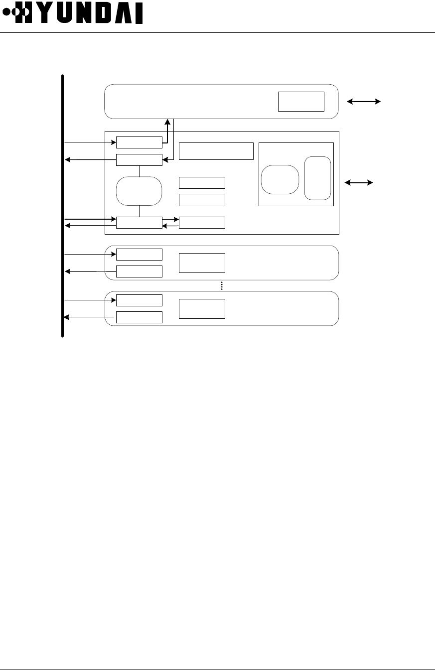
User’s Manual
PROPRIETARY & CONFIDENTIAL 5-7
Figure 5.4 Block Diagram of BMP
5.3.1.1 BMPA-B2 (BTS Main Processor Assembly-B1)
BMPA-B2 consists of CPU (MPC860) and Packet Router, Alarm collector, and it connects with BSC through
HLTA-B1. BMPA-B2 processes call setup, call release, recovery from malfunctioning, and maintenance, it
reports the related data to CCP of BSC, and it controls every unit in BTS by the command of CCP. As for
capacity, it supports 1-FA (1-FA is configured up to 3-sector).
4 SCC and 2 SMC around MCP 860, CPU of BMPA, carries out node function for communication between
the units and status management of Micro-BTS.
BMPA collects control and status information of RRU via SCC4 which provides communication channel with
AIDU, and receives status and environmental alarm information in RPU ( Rectifier Power Unit ) via SCC3.
SCC1 is used as the communication path with BMPA-B2, which is equipped in 2nd cabinet. TOD from STFU
is also provided via SMC1.
Clocks for Micro-BTS, SYS_CLK, EVEN_SEC are provided from STFU -B1and distributed to each unit in
Micro-BTS.
BMPA-B2
CDCA 0
CDCA 3
HLTA - B1
HDLC
HDLC
Packet
Router
HDLC
Alarm & Control
FLASH
DRAM
DPRAM
Processor
CPU
(MPC860)
SCC
(1~4)
SMC
(1~2)
HDLC
HDLC
HDLC
HDLC
DPRAM
DPRAM
Trunk
Module
BSC
Other Side
BMP
(SCC 1)
TX/RX DATA

User’s Manual
PROPRIETARY & CONFIDENTIAL 5-8
BMPA-B2 has the self-diagnosis function for each module, transmission and receiving power measurement
function and TPTL function and also carries out the trunk interface function for E1/T1, main processor
function and arbitration master function among the channel cards. And BMPA-B2 generates 19.8MHz clock
in order to provide 4.95MHz clock which is necessary to carry out baseband IF QPSK. In addition, BMPA-B2
takes charge of the role of the backboard in which CDCA-B1, BICA-B1, HNTA-B1 can be equipped.
One BMPA-B2 is designed to support 1FA/3Sector/1st cabinet. In case of expansion to 2FA/3Sector, another
BMPA-B2 in the second cabinet is required and each status of 2nd cabinet is reported to BMPA-B2 of first
cabinet via SCC.
5.3.1.2 HLTA-B1 (High performance IPC Link T1 Board Assembly-B1)
HLTA-B1 contains 1 T1 trunk interface and 1 Modem interface, and if it has two main functions. The first is
to perform the function of trunk line interface to mutually connect BMPA-B2 with BSC through digital trunk.
The second is to perform the function of Modem line interface to mutually connect BMPA-B2 with BSM of
BSC through Telephone line. Modem is optional and is used as a sub-path for status monitoring of BTS only
when trunk is abnormal.
Trunk interface of HLTA-B1 is connected serially with two twisted pair trunk cables, and It can recover
signals up to 36dB cable attenuation (long-haul). A user can control transmitter pulse shape and receiver
equalizer at various trunk cable lengths with the strap JP1. BMPA-B2 controls HLTA-B1 with extended CPU
buses.
5.3.2 DU (Digital Unit)
DU is functionally located between XCVU and BMP, and consists of CDCA-B1 and BICA-B1. CDCA-B1
performs digital signal processing for CDMA modulation and demodulation. BICA-B1 is functionally located
between CDCA-B1 and XCVU, and provides digital interface to CDCA-B1, and 4.95MHz IF interface to
XCVU. BMPA-B2 transmits and receives packets of DU to/from HLTA-B1, and collects the conditions of DU.
Power module provides power to these boards. The signal flow diagram in DU is as follows. (Refer to Figure
5.5)
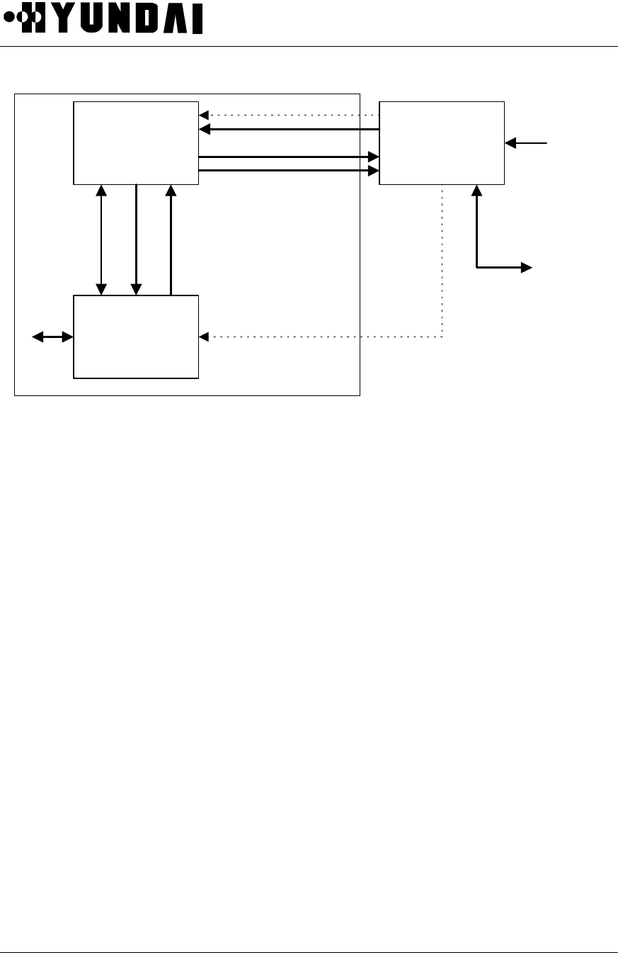
User’s Manual
PROPRIETARY & CONFIDENTIAL 5-9
CDCA-B1 BMPA-B2
BICA-B1
Tx DATA
STREAM
Tx DATA cntl
STATUS
Rx DATA
SAMPLE
CLK HDLC
HDLC
STATUS
CLK from
STFU
HDLC
To/from
HLE(T)A
CLK
CNTL
STATUS
To/from
XCVU
DU
Figure 5.5 Signal flow diagram in DU
5.3.2.1 CDCA-B1 ( CDMA Digital channel Card Assembly-B1 )
CDCA-B1 is located in the digital unit, and its main function is the CDMA digital modulation and
demodulation for processing calls from/to MS (Mobile Station). CDCA-B1 outputs CSM output to BICA-B1
for forward link, and receives 4-bit digital samples of each I and Q channel from BICA-B1 for reverse link.
CDCA-B1 interfaces BSC via BMPA-B2 and HLTA-B1 to exchange data for traffic and control information.
• Main components of CDCA
Processor : i960
Cell site modem : CSM
Interface with BMPA : RS-485
Memory size : 2M Byte (SRAM )
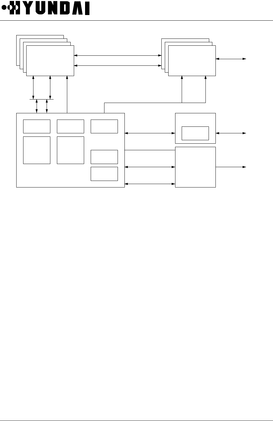
User’s Manual
PROPRIETARY & CONFIDENTIAL 5-10
DPRAM HDLC
Packet
Router
DPRAM
SCC
SCC
CPU
BMPA-B2
Trunk I/F
HLTA-B1
STFU-B1
CDCA-B1 BICA-B1
¥á,¥â,¥ã
0~3
EVEN_SEC
SYS_CLK
AGCAlarmDATA,
CLK(+,-)
Status/Control
XCVU
SYS_CLK,
EVEN_SEC, 10MHz
TOD
TX/RX DATA ¥á,¥â,¥ã(I,Q)
XCVU
T1
Status/Control
EVEN_SEC
SYS_CLK
BSC
10MHz
Figure 5.6 DU and external interface diagram
5.3.2.2 BICA-B1 ( Base-band & IF Conversion Card Assembly-B1 )
BICA-B1 is located in the digital unit. For the reverse link, 6 IF signals are inputted from XCVU. Those 6 IF
signals are inserted to the corresponding BICA-B1, and IF signals are passed to BPF’s (band pass filter)
centered at IF frequency, and the received signal is automatic-gain-controlled to produce a fixed level of
received power. Mixers in BICA-B1 uses 4.95 MHz (0&90 degrees) reference frequency to produce the
baseband signals of in phase (I) and quadrature (Q) components. The I and Q baseband components are
transformed to 4-bit digital samples at a rate of 9.8304 MHz. And the I digital samples for one antenna are
multiplexed with the I digital samples for the other antenna, and the Q digital samples for one antenna are
multiplexed with the Q digital samples for the other antenna. So the multiplexed samples are inputted to
CDCA-B1 at a rate of 19.6608MHz. The AGC values are reported to BMPA-B2.
For the forward link, BICA-B1 accepts and digitally combines even and odd streams of I and Q from up to 4-
CDCA-B1, and converts the combined digital signal to analog through DAC (digital to analog conversion),
modulates base-band (0~630 kHz) signal to a IF (4.95 MHz) QPSK signal, and transmits the IF signal to the
corresponding XCVU. One BICA-B1 covers only one sector. BICA-B1 can report parity errors to the
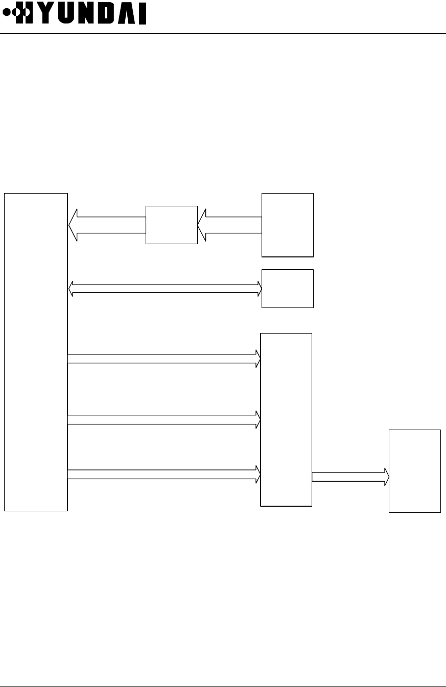
User’s Manual
PROPRIETARY & CONFIDENTIAL 5-11
corresponding CDCA-B1.
5.3.3 TFU (Time & Frequency Unit )
The main purpose of TFU is to synchronize time and frequency between whole BTS’s and between all the
units in a BTS. Following figure is a block diagram of TFU ( Refer to Figure 5.7)
STFU-B1
BMPA-B2
10MHz, 19.6608MHz, PP2S(Differential PECL)
10MHz(Sinewave)
GPS
Arrester
Satellites
Signal GPS
Antenna
Satellites Singal
PC
Control Signal(RS-232C)
TOD(RS-232C)
SYNU-B1
10MHz(Sinewave)
Figure 5.7 TFU-A1 Block Diagram

User’s Manual
PROPRIETARY & CONFIDENTIAL 5-12
5.3.3.1 STFU-B1(Synchronized Time & Frequency Unit - B1)
The STFU-B1 is a GPS disciplined time and frequency generator. The instrument is a combination of a
Stratum 1 level Primary Frequency Source and a Distribution System, which provides 10MHz, 19.6608MHz,
1PPS, PP2S and TOD(Time Of Day).
The STFU-B1 communicates with BMPA-B2 to monitor and to transmit the TOD by means of RS-232C
serial communication.
5.3.4 RFU (Radio Frequency Unit)
RF part of Micro-BTS consists of XCVU and Ant Subsystem (AIU-RRU, AIDU-AAU).
XCVU consists of SYNU, UPCU, DNCU, LODU and XVBB. SYNU (Synthesizer Unit) provides reference
frequency to RFU. UPCU (Up Conversion Unit) carries out up conversion which converts IF signal to RF
signal on forward link and DNCU (Down Conversion Unit) carries out down conversion that converts RF
signal to IF signal on reverse link. LODU takes charge of distribution of local signal and XVBB takes charge
of interconnection of each module.
RFU consists of AIU and RRU. AIU is connected to RRU with the cable and monitors the status and alarm
of RRU, controls RRU. RRU is composed of High Power Amplifier on forward link, Low Noise Amplifier on
reverse link and BPF (Band Pass Filter). In accordance with field application, type of the antenna (internal
antenna or external antenna), type of the amplifier, and the application of RRU is determined.
There are two types of the each module in the manual, one is used for 800MHz and the other is used for
1.9GHz described by the suffix of “-B1”. The difference of both is only the operation band, they play a same
roles.
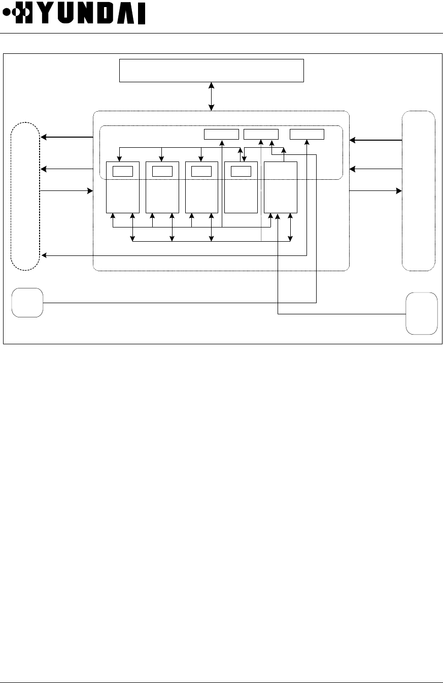
User’s Manual
PROPRIETARY & CONFIDENTIAL 5-13
From/To BMPA-B2
UPCU DNCU
( 0 ) DNCU
( 1 ) LODU SYNU
CON CON CON CON From
/TO
BICA
-B1
From
STFU
-B1
RPU
ConnectorConnectorConnector
RX Signal
( 0, 1 )
Overhead
Signal
4.95MHz
CDMA Signal
Control signal Status Signal
Fault Signal
XCVU
XVBB-B1
RX Signal
( 0, 1 )
Overhead
Signal
RF Band
CDMA Signal
Alarm Signal, Control Signal, Power
Power(DC 27V/ ¡¾15V /12V) 10MHz(REF, Clock)
Power
Alarm Signal, Control Signal
RF-Local, IF-Local Signal
From
/TO
AIU
(or
IDU)
Figure 5.8 XCVU block diagram
5.3.4.1 XCVU(Transceiver Unit)
5.3.4.1.1 DNCU (Down Conversion Unit)
DNCU carries out first down-conversion of input RF signal from RRU using RF-Local signal of SYNU and
carries out second frequency down-conversion to 4.95MHz by using RXIF-Local signal of SYNU after
characteristic improvement to CDMA band signal via the SAW filter. This 4.95MHz signal is transferred to
digital signal processing part.
DNCU is designed to get fixed output power that is not changed by acquisition of input signal by using AGC
Loop.
5.3.4.1.2 UPCU (Up Conversion Unit)

User’s Manual
PROPRIETARY & CONFIDENTIAL 5-14
UPCU carries out first frequency up-conversion of 4.95MHz IF signal from digital signal part using TXIF-
Local signal of SYNU and carries out second frequency up-conversion to required frequency band using
RF-Local of SYNU after characteristic improvement to CDMA band signal using the SAW filter. Up-
converted second signal is transferred to RRU.
5.3.4.1.3 SYNU (Synthesizer Unit)
SYNU consists of RF-Local, TXIF-PLL, and RXIF-PLL and generates RF-Local signal whose output
frequency is changed in accordance with the assigned channel, TXIF-Local signal, and RXIF-Local signal
based on 10MHz sine wave of GPS receiver. The generated RF-Local signal, TXIF-Local signal and RXIF-
Local signal are transferred to DNCU, UPCU.
5.3.4.1.4 LODU (Local Oscillator Distributor)
LODU distributes RF Local signal, TXIF-Local signal and RXIF-Local signal generated by SYNU to UPCU
and DNCU and is equipped in XCVU as one module type.
5.3.4.1.5 XVBB (Transceiver Back Board)
XVBB takes charge of distribution of alarm and control signal between DU and XCVU and provides power
from power module to AIU and XCVU. And XVBB also transfer alarm and control signal of RF shelf.
5.3.5 Antenna Subsystem
There are two types of antenna subsystems in Micro-BTS; those can be selectively applied to as operator’s
requirement. Antenna subsystem consists of main module which is located in antenna tower and interface
module which connects with Micro-BTS. Applicable antenna subsystems are AAU-AIDU and RRU-AIU.
AAU-B1, AIDU-B1, RRU-B1, and AIU-B1 is used for 1.9GHz frequency band.
5.3.5.1 RRU-B1 and AIU-B1

User’s Manual
PROPRIETARY & CONFIDENTIAL 5-15
5.3.5.1.1 AIU-B1 (Antenna Interface Unit)
AIU-B1 of Micro-BTS is interface part with RRU-B1 and consists of 2 Way Splitter, Bias-T and Bias-T &
Duplexer.
Drawn with 1Sector Configuration
Bias-T, Duplexer : Included Lightening Protection
RX0/TX
RX1
RRU
Transceiver
HP
A
DOWN
(0)
DOWN
(1)
AIU
DUP
Splitter
UP
Bias-T
Arrester
Splitter Duplexer
LNA
FilterLNA
Processor
Arrester
Duplexer
Bias-T
Regulator
TX 0
RX 0
RX 1
Monitor
&Control
Figure 5.9 RRU-B1 block diagram
AIU-B1 is equipped in the main unit of Micro-BTS and provides interface with RRU-B1. M & C module in
AIU-B1 takes charge of status monitoring and controlling of each RRU-B1. AIU-B1 contains FSK Modem
function that can communicate with RRU-B1 and reports information about communication result via SCC in
BMPA-B2.
2-Way Splitter has two paths used to provide Rx signal. In case of second cabinet expansion, one path of 2-
Way Splitter is connected to the first cabinet that accommodates first carrier (FA) and the other path of 2-
Way Splitter is connected to the second cabinet that accommodates second carrier (FA). Bias-T that
contains arrester function multiplexes RF signal and DC power, and protects from the lightening.
Duplexer is used to multiplex RF signal, DC power and FSK modem signal for monitoring and controlling
RRU. Duplexer also contains the arrester for the lightening protection.
Monitor & Control Module takes charge of status monitoring and control for 1FA / 3Sector (three RRU-B1s)
and contains FSK Modem for communication with RRU. Communication with BMP is completed via RS-232
protocol.

User’s Manual
PROPRIETARY & CONFIDENTIAL 5-16
5.3.5.1.2 RRU (Remote RF Unit)
The RRU-B1 specifications of Micro-BTS are as the below table.
Item RRU Remark
Transmission Power 10W 1 Module
Dimension (H x W x D) 400 x 350 x 150 1 Module
Antenna External Antenna
Function Rx Diversity Support
Output power of RRU is 10Watts and it is lower than output power of Macro-BTS.
The coaxial cable is used for interface between the Main Unit. RRU and 3 coaxial cables which are
connected to each sector supporting Rx diversity.
In using external Ant, two Ant. per sector are needed because the antenna of the RRU is duplex type.
BMP in Main Unit can control all of status in RRU-B1 and it is useful for operation and maintenance of
Remote Module.
5.3.5.2 AAU-B1 and AIDU-B1 (1.9GHz)1
5.3.5.2.1 AAU-B1 (Active Antenna Unit)
AAU-B1 consists of integrated RF/antenna modules (ARM units) grouped in radiating arrays for transmit
and receive. The whole RF/antenna array for the base station is tower-mounted and consisted of four ARM
units and an array of four antenna groups. Each ARM is self contained and controllable by its internal micro-
controller.
AAU and AIDU is used for 800MHz frequency band and they play a same roles with AAU-B1 and AIDU-B1.
(1) AAU-B1 Block Diagram
1 In 800MHz band, AAU and AIDU are used.
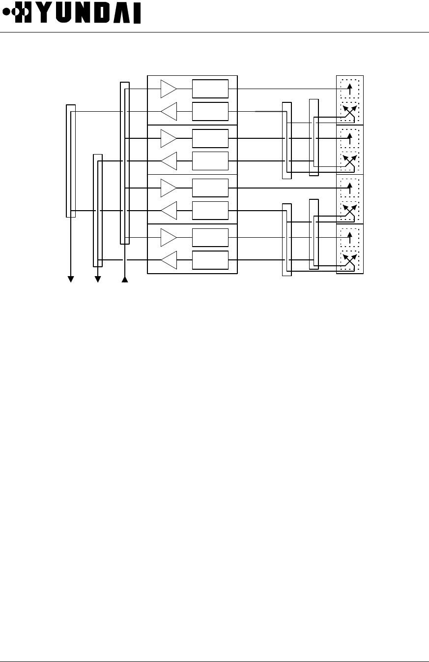
User’s Manual
PROPRIETARY & CONFIDENTIAL 5-17
BPF
BPF
BPF
BPF
BPF
BPF
BPF
BPF
RX_0 RX_1 TX
CombinerCombiner ARM Antenna
Figure 5.10 AAU-B1 Block Diagram
(2) AAU-B1 Specification
1) Tx Channel
Frequency Range : 1960 ~ 1990 MHz
Gain : 52 dB (including the antenna gain : 13 dBi,
each ARM Tx gain : 33 dB 4)
EIRP : 22 dBW
Polarization : Vertical
Hor. Beamwidth : 85.6
El. Beamwidth : 14.08
2) Rx Channel
Frequency Range : 1880 ~ 1910 MHz
Gain : 49 dB (including the antenna gain : 13 dBi,
each ARM Tx gain : 30 dB 4)
Polarization : Dual slant linear

User’s Manual
PROPRIETARY & CONFIDENTIAL 5-18
Hor. Beamwidth : 87.4
El. Beamwidth : 14.25
5.3.5.2.2 AIDU-B1 (Active antenna InDoor Unit )
AIDU-B1 is a indoor control unit and interfaces the AAU-B1 with the BTS. It relays the Tx and Rx signals,
provides DC power to the ARM units, and communicates with AAU-B1 for the monitoring and control
purposes.
The unit consists of 3 Bias-T blocks and controller. Each Bias-T block includes three Bias-T circuits one for
Tx and the others for Rx. Tx Bias-T circuit multiplexes RF signals with DC voltage between the ARM units
and AIDU-B1. It includes the 30dB gain amplifier possible to control gain of 15dB. Rx Bias-T circuit
multiplexes RF signal with low frequency signaling between the ARM units and AIDU-B1. It includes the
15dB gain amplifier possible to control gain of 15dB.
The controller provides the following functions:
(1) Communication with the ARM
(2) Monitoring of the ARM units and radiating arrays status
(3) Communication with BMPA-B2
(4) Saving of system configuration

User’s Manual
PROPRIETARY & CONFIDENTIAL 5-19
5.3.6 BTU (Micro-BTS Test Unit)
The functions of BTU are measurement of transmission/receiving power level,
measurement of VSWR and measurement of TPTL, etc. And these functions are carried
out in RRU. Status data and alarm signal in RRU is transferred to AIU via modem, and the
collected alarm signal in AIU is reported to BMP with RS-485 protocol and processed.
AIU RRU-B1
Arrester
& Duplexer
HPA
Duplexer BPF
Modem
Processor
M&C
Modem
Frequency
BMPA-B1
Figure 5.11 BTU block diagram
The functions of BTU are as follows
(1) Measurement of transmission power level
This function is carried out by measuring output voltage value for signal strength at the alarm output
terminal of HPA Monitor in RRU. Measured value is transferred from RRU to BMP in Main Unit via the
modem and linear voltage value can be checked in BSM by user.
(2) Measurement of receiving power level
This function is carried out by measuring receiving signal level value while monitoring RSSI value in
DNCU of XCVU.
Measured value is transferred to BMP of Main Unit and can be checked in BSM by user.

User’s Manual
PROPRIETARY & CONFIDENTIAL 5-20
(3) Measurement of VSWR
User can recognize Fail or Normal by comparing signal strength value of reflected power at the alarm
output terminal of HPA monitor in RRU. Measured value is transferred from RRU to BMP of Main Unit via
the modem. User can check HPA status in BSM.
(4) Measurement of TPTL ( Transmitter Power Tracking Loop )
This function is carried out by controlling transmission power gain at variable ATT in front of HPA in RRU.
This function is operated by S/W and every status is reported to BMP.
User can check status in BSM.
5.3.7 RPU
RPU-B3 is a power supply for Micro-BTS. It has various DC outputs needed for each units at MICRO-BTS. It
has power status monitoring and report function. It has also battery back-up function.
RPU-B3 can be connected with external power supply (RPU-B4) when output capacity expansion is needed.
RPU-B4 is 27V single output AC/DC converter. When RPU-B4 is connected to RPU-B3, they have load
balance function.
RPU-B3 has 3 switches – AC input ON/OFF, RPU-B4 input ON/OFF, and DC outputs ON/OFF.

User’s Manual
PROPRIETARY & CONFIDENTIAL 5-21
5.4 S/W Structure and Function
5.4.1 Overview
Micro-BTS Software, which is designed for the purpose of maximum reliability and efficiency in order to
provide operation & Maintenance function and smooth interfaces between BSC and MS, complies to the air
interface specifications with MS.
Micro-BTS Software has Call processing function and Operation & Maintenance function.
When the system allocates Overhead (Sync, Pilot, Access, Paging) channel and Traffic channel, Call
processing function provides the Algorithm which support inter-channel Redundancy concept using
duplication and inter-channel common ownership. It should provide effective Call flow with adjacent BSCs
and support Variable packet size for Traffic packet.
Micro-BTS operation and Maintenance function performs generally Loading, Diagnostic, Alarm, Status,
Resource management etc. And it supports the Software which improve the system reliability through
removal of critical trouble factors. So the system uses the resource efficiently.
As Micro-BTS Software should perform multiple call processing simultaneously, it executes on the Operating
System which supports Real time Multi-Tasking function. Actual Operating System is applied to Micro-BTS
Control Block and Traffic Channel Processing Block.
The software which is used for Micro-BTS should improve BTS performance and provide facilities for the
Operation and Maintenance.
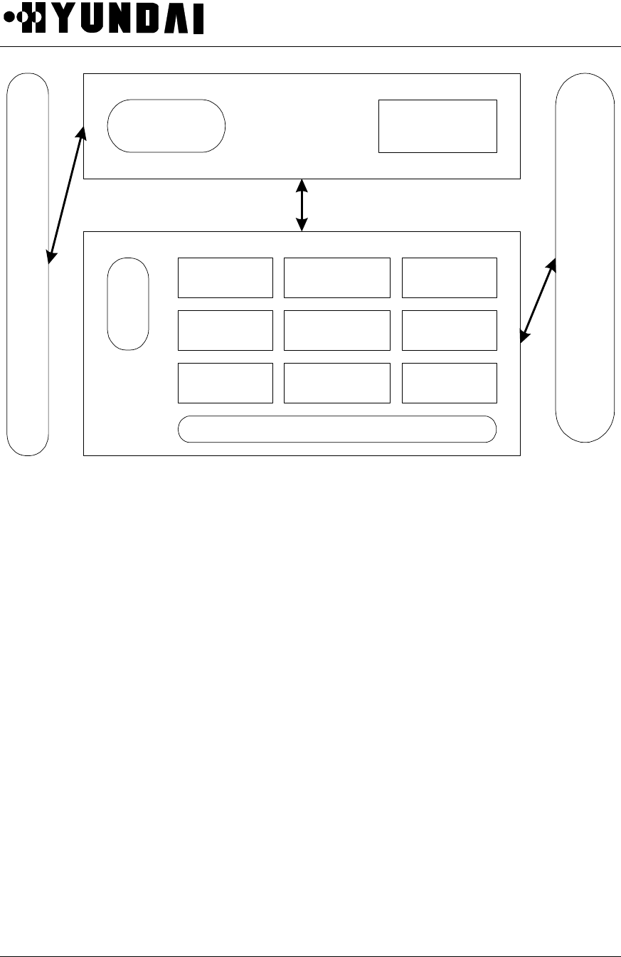
User’s Manual
PROPRIETARY & CONFIDENTIAL 5-22
DU
CAI & Traffic
Processing
OS
TSB
CCP
Other
BTS
Blcok
BMP
Diagnostic
Call Control
Loading
Status
Handling
H/W Fault
Management
Measurement
& Statistic
Database
Resource
Allocation
Resource
Management
PLD
OS
MS
Figure 5.12 Micro-BTS Software Structure
5.4.2 Basic Functions
Micro-BTS which is located between Base Station Controller (BSC) and MS, executes the management of
wireless link during incoming/outgoing call processing.
It is a network element performing various functions for wireless Call processing.
Each sub-function in Micro-BTS software is described as the following features.
5.4.2.1 Loading Function
Execution files and data files required by sub-blocks ( BCP, CCC ) of Micro-BTS to execute their unique
functions are managed by CCP of BSC. Upon receiving the loading request from Micro-BTS system, the
CCP transmits the corresponding file to Micro-BTS in accordance with the prescribed procedure to execute
the initialization of the corresponding processor.
(1) Processor Restart Function
At the time of system installation or when it is impossible to maintain normal services due to a critical fault

User’s Manual
PROPRIETARY & CONFIDENTIAL 5-23
in the processor, the processor can be restarted either by Hardware recovery method (processor
reloading by power on/off , reset) of which procedure begins with supply of primary power supply to the
system or by on-demand processor restart method which is executed in several steps when necessary.
(2) Restart by MMC Command
At the time of Software version change or test, this loading method is used to recover the processor after
processor is drop off by operator with MMC. Loading with MMC command is divided into Level 0 and
Level 1. The operator can select the loading level according to pertinent data.
• BMP Level 0 Command :
Processor restarts and requests CCP to receive the loading data. At this time, low level CDCA also
restarts and recovers after loading.
• BMP Level 1 Command :
Processor restarts from OS and receives loading block from the channel card. At this time, low level
CDCA also restarts and recovers after loading.
At the time of Software version change or test of the call processing application block, CCC loading of
loading functions is used to restore the system through reloading data after all processor is drop off. As
RFU block consists of Main Unit and Remote Unit, the operator can recover the card assembly by
restarting it with MMC command at the time of function failures in Main Unit and Remote RF block.
(3) Restart by H/W ( Power, Reset )
• BMP :
When it is impossible to maintain normal services due to a processor fault during system installation,
initialization or operation, it is possible to reload BMPA with power on-off or reset. This reloading is
made by first turning down all the processors in the system and then recovering them with reloading.
When high level processor restarts to recover its normal state, all low level processors are recovered
with reloading.
• CCC :
When it is impossible to maintain normal services due to a processor fault during initialization of call
processing application block, it is possible to reload with power on/off or reset.

User’s Manual
PROPRIETARY & CONFIDENTIAL 5-24
5.4.2.2 Replacing of Application Block
• This is an on-line command function to be applied to a processor of the block in which a fault occurs
during system operation or for which a function is added.
• If the block to be applied is running on a processor, the processor restarts to be reloaded from its high
level processor.
• If the block to be applied is only loaded on a processor but has to be downloaded, only the block is
downloaded from its high level processor.
When it is required to add or delete a block during operation by needs of the operator, it is possible to load
the specified block to the corresponding block by adding or deleting the block with MMC command.
5.4.2.3 Diagnostic Function
As Micro-BTS is outdoor type BTS, it is manufactured very firm. So Diagnostic function by Software is very
important in a view of system reliability.
Micro-BTS has various functions including Output Control function (TPTL), Loop Back Call function, and
Diagnostic function of Channel Elements etc..
• BTS Output Control (Transmit Power Tracking Loop, TPTL Adjustment function)
This function measures the final output of BTS for each sector and each FA in order to tune it to the
desired power level. It is used to adjust the radius of cells uniformly in each sector. It measures and
tunes power at the final output end, which allows to correct errors due to change in the system
characteristics (by the influence of temperature and the like).
• Loop Back Call function
Loop Back call allows the base station to measure the data Tx / Rx performance of the mobile station.
The base station creates traffic packets and transmits them to the mobile station, and the mobile
station delays for calls and then forwards back the received packets to the base station. Then, the

User’s Manual
PROPRIETARY & CONFIDENTIAL 5-25
base station compares them with the original packets to calculate the frame errors.
• Channel Elements diagnostic function
The Micro-BTS continuously requests as many polling messages as requested by the operator,
directly to the channel elements. It compares the number of accepted and requested to understand
the corresponding resource status.
5.4.2.4 Alarm and Fault Control function
This is the function to collect all alarms generated in Micro-BTS and report them to BSM. Types of faults
and alarms detected in Micro-BTS are listed below.
• Main PBA/Unit Function Failure Report
• Processor Fault Report
• Traffic Congestion and Overload Control Fault Report
• Equipment OOS ( Out Of Service ) Alarm Report
• Fan Fault Report
• Temperature, Door Open, Noise Fault report
• Rectifier Fault Report
• Input Power Fault Report
• System Clock Part Fault Report
• System RF Part Fault report
• Channel Element Fault report
5.4.2.5 Status Management function
The Status management function of a Micro-BTS includes Overload Control Function, Overhead CE Status
Control Function, Traffic CE Status Control Function, Traffic / Control Link Status Control Function, Subcell
Control Function, STFU Status Control Function, RFU Status Control Function, RRU Status Control
Function, and Automatic Blocking Function etc.
• Overload control
The Overload control is the function to prevent Micro-BTS resources from shifting into abnormal status
by interrupting call services in advance. The abnormal status means two situations : in one case that

User’s Manual
PROPRIETARY & CONFIDENTIAL 5-26
the BMP is overloaded in its processing capacity and shifts into a state of being unable to provide call
services ; and in the other case that handoff of existing calls cannot be made and subsequently the
call services are interrupted as all the resources of TCE (Traffic Channel Element) are already
allocated to newly made calls. Overload control is to prevent in advance these situations from arising.
• Overhead CE status control
Micro-BTS manages the status of overhead CEs (Pilot/Sync channel element, Paging channel element
and Access channel element). It always monitors whether the current overhead CEs are normal or not,
and informs the BSM when a fault occurs in an overhead CE. In the case where the overhead CE is
duplicated, the standby overhead CE is activated to continue the call service. If it is not duplicated as
active/standby CEs, Micro-BTS makes the current traffic CE replace the faulty overhead CEs to
continue the call service.
• Traffic CE status control
Micro-BTS has the function to monitor the status of CEs activated as traffic CEs and to manage the
status as common data. When a fault occurs in a traffic CE and interrupts the call service, Traffic CE
status control prevents calls from being allocated to that traffic CE so that call service is not
interrupted. It also executes the audit function to monitor call service status of entire traffic CEs and
maintain the accurate traffic CE status at all times. In order to prevent situations where call service to a
certain traffic CE is not possible because the traffic CE is thought to be setting up a call though it is
actually not in the call setup stage and normal call release becomes impossible owing to some
unavoidable reasons.
• Traffic / Control Link status control
This is the function by which Micro-BTS manages the Traffic Link and Control Link status as the common
data so as to allow communication between Micro-BTS and BSC. It manages the channel status so
that the Micro-BTS and BSC can interchange call data and control signals. It always provides
information of available links.
• Subcell control
When a MS to be serviced by the subcell is not provided with the call service, system sends the fault
information on the subcell to the MS so that it can be always provided with the call service by using the
call services of other subcells.

User’s Manual
PROPRIETARY & CONFIDENTIAL 5-27
• STFU status control
STFU generates the time and clock required for Micro-BTS and provides peripheral devices with the
clock. It provides the TOD to BMP and the BMP broadcasts the received TOD information to each
device which need TOD information. STFU monitors a GPS status and then report them to BSM.
• RFU status control
RFU is the part which observe all status of Input / Output in Micro-BTS, and Micro-BTS monitors the
status of UPCU, DNCU, SYNU, AIU. When a fault is detected in any of them, it reports the fault
occurrence to the BSM.
• RRU status control
This is the part which monitors all the status of RRU. It monitors the status of RRU through AIU in Main
Unit. When a fault is detected, it reports the fault occurrence to the BSM.
• Micro-BTS Automatic blocking
MS acquires the pilot transmitted from Micro-BTS to initialize the MS data and requests the call
services from the Micro-BTS to which it belongs. If this time, all communication channels connected to
BSC are out of service, it is impossible to make any call service. However, as all status are normal,
Micro-BTS continuously transmits the pilot and MS initializes its data with this pilot and requests the
call service. In this case, Micro-BTS should not transmit the pilot so that the MS may not request the
call service with its pilot. Micro-BTS automatic blocking is the function by which it controls the
communication channel status and does not transmit its pilot when a fault is detected in the channel.
This function is also applied to the case when a fault occurs in BSC. When Micro-BTS status is normal
but BSC to which it belongs has a fault, MS cannot be provided with the call service and thus, the
Micro-BTS should not transmit its pilot to the MS.
5.4.2.6 Resource Management Function
The resource management of a Micro-BTS includes Configuration information and Operation information
Display function, Blocking function, Unblocking function, Operation Information changing Function, Neighbor
add/delete function, and FA extend/delete function.
• Configuration Information and Operation Information Display

User’s Manual
PROPRIETARY & CONFIDENTIAL 5-28
Micro-BTS displays the current configuration and operation information to the operator. BSM sends the
configuration and operation information about the corresponding Micro-BTS, and the Micro-BTS
displays the information on the BMP monitor.
• Blocking Function
The Micro-BTS has the function to block the configuration information required for all processing using
MMC command. When the configuration information is blocked, the Micro-BTS excludes the
corresponding resources from the call allocation resources and does not allocate any call to the
resource. Objects that may be blocked are CDCA, traffic channel elements, paging channel elements,
access channel elements and pilot/sync channel elements. When blocked, the corresponding resource
is excluded from the call allocation resources. It is a principle to block one resource with one command
but it is also possible to set the range of blocking if necessary.
• Unblocking Function
When a resource required for call processing is blocked, the Micro-BTS can unblock the resource
using MMC command. Objects that may be unblocked are CDCA, traffic channel elements, paging
channel elements, access channel elements and pilot / sync channel elements, as in blocking. Once
unblocked, the resource which has been excluded from call allocation resources can be allocated as a
call resource again. It is a principle to unblock one block with one command but it is also possible to
set the range of unblocking if necessary.
• Function to change Operation Information.
Micro-BTS has the function by which the operator changes every data related to call processing and
operation, and maintenance. The call processing related data includes the parameters related to
handoff, and the operation and maintenance related data includes parameters related to overload
control.
• Function to Add / Delete Neighbor
The operator can delete or add the list of neighbors required for Micro-BTS to execute the handoff
function. On the basis of this neighbor data, Micro-BTS executes handoffs.
• Function to Extend / Delete FA
It is possible to extend or reduce FA on demand by the operator. All of the configurations

User’s Manual
PROPRIETARY & CONFIDENTIAL 5-29
corresponding to the extended FA are activated to be the objects of call processing and alarm
processing, and such operation and maintenance functions as status control, loading and diagnostics,
while the configurations corresponding to the deleted FA are inactivated to be excluded from the
objects of call processing and alarm processing, and such operation and maintenance functions as
status control, loading and diagnostics.
5.4.2.7 MS Call processing Function
The software function of Micro-BTS is designed to support subscriber requirement which is processed
based on the request of terminal as well as to provide functions which are processed based on the Micro-
BTS requirement.
This function includes MS originating call function, MS terminating Call function, Softer Handoff function,
Soft handoff function, Inter-FA Hard Handoff function, Frame Offset Hard handoff function, Registration
function, Order function, Feature Notification Service function, Data Burst Service function, Authentication
service processing function, call Processing Simulation function, Overhead channel function, and Power
Management Processing function.
• MS Originating Call Function
When a MS requests Micro-BTS for an originating call, the Micro-BTS sets up a traffic channel,
specifies the resources allocated at the Micro-BTS to the MS to execute the call processing function of
the Micro-BTS and MS, and requests BSC to set up the call.
• MS Terminating Call Function
Micro-BTS sends a paging message to a MS to call the MS. When the MS requests the Micro-BTS for
a terminating call, the Micro-BTS sets up a traffic channel, specifies the resources allocated at the
Micro-BTS to the MS to execute the call processing function of the Micro-BTS and MS, and requests
BSC to set up the call.
• Softer Handoff Function
When a MS requests Micro-BTS for ‘softer add’, ‘softer drop’, or ‘softer swap’ function, the Micro-BTS
resets the corresponding resource so that the MS can execute the handoff function.

User’s Manual
PROPRIETARY & CONFIDENTIAL 5-30
• Soft Handoff Function
When a BSC requests Micro-BTS for ‘soft add’, ‘soft drop’, or ‘soft swap’, the Micro-BTS allocates the
corresponding resource so that the MS can set up/release the corresponding traffic, and transmits the
resource allocated at the time of handoff to the BSC.
• Inter-FA Hard Handoff Function
When a BSC requests for ‘soft add’, if the corresponding traffic resources are all busy, Micro-BTS sets
up a traffic corresponding to another RF and transmit it to the BSC to proceed with the call processing.
In the case of Micro-BTS in which a dummy pilot or common pilot is set up, BSC executes inter-FA
handoff for the corresponding MS.
• Frame Offset Hard Handoff Function
When a BSC requests for ‘soft add’ and the corresponding frame offset resources are all busy, Micro-
BTS allocates other frame offset resources and transmits those frame offset resources to the BSC so
that the BSC can execute the frame offset hard handoff.
• Registration Function
Upon registration request from MS, Micro-BTS transmits BS_Ack_Order to stop transmission from the
MS and transmits the registration message of MS ( power up, power down, timer base, zone base,
parameter change, order, etc.) to BSC.
• Order Function
Micro-BTS executes such functions for the corresponding MSs as ‘BS_Ack_Order’, the command to
stop transmission from MS; ‘Lock Until Power Cycle Order’, the command to release MS call; ‘Release
Order’, the registration commands; Registration Reject / Accept / Request Order.
• Feature Notification Service Function
Micro-BTS executes such function for the corresponding MSs as Display, Called Party Number, Calling
Party Number, Signal and Message Waiting.
• Data Burst Service Function
Micro-BTS executes the function to transmit and receive Data Burst messages to and from the
corresponding MSs.

User’s Manual
PROPRIETARY & CONFIDENTIAL 5-31
• Authentication Service Processing Function
Micro-BTS specifies the settings required for MS to execute authentication, and executes
Authentication Challenge and SSD Update functions by interworking with MSC so that the MS can
execute authentication.
• Call Processing Simulation Function
Micro-BTS executes such simulation functions related to call processing as Markov call, Auto Markov
call and RF test call, and paging performance test and access performance test.
• Overhead Channel Function
Micro-BTS implements Redundancy Algorithm on Pilot/Sync/Access Channel and Paging channel.
Micro-BTS executes dynamic processing function so that the overhead channel functions can be
normally executed by setting another channel as an overhead channel when the original overhead
channel has a fault and can not execute its own functions.
• Power Management Processing Function
By interworking with RFU(Radio Frequency Unit), Micro-BTS executes such functions as Breathing,
Wilting and Blossoming to manage the cell radius of Micro-BTS depending upon its performance and
on demand by the operator.

User’s Manual
PROPRIETARY & CONFIDENTIAL 5-32
5.4.2.8 BMP Software Structure
The basic software of Micro-BTS is divided into Call processing function and Operation and Maintenance
function. Micro-BTS is configured with BMP and DU by device.
Primary Processor of the Micro-BTS is configured with Call processing function, System operation and
System maintenance function logically. Generally, System operation function executes loading, resource
management, measurement and statistics, database access function for the management of configuration
and resource which is needed for Micro-BTS operation.
System maintenance function executes diagnostic function, Status monitoring function, Fault processing
function, etc.
Call processing function which is the main function of the Micro-BTS executes overhead call processing and
manages various handoff. Also it allocates traffic channels directly in Micro-BTS and release them.
The basic sequence of call processing is followings.
It manages each device and interfaces with a CCP in the BSC for the call processing procedures so as to
control MS originating call (MS→BTS→BSC→MSC) and MS terminating call (MSC→BSC→BTS→MS). This
procedure is called by ‘BTS call control. When MS requests originating call to BTS, it sends call setup
requirement to BCP on access channel. Then operations related to Originating call starts in BCP
(MS→ACE→ BCP).
In case of MS terminating call, MSC receives request for terminating call.
After MSC determines paging area, it sends paging message to BSC. Then CCP in the BSC transfers the
paging message to BCP. Then BCP processes the operations related to terminating call.
The software structure of BMP is followings.
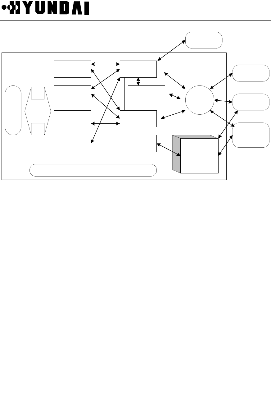
User’s Manual
PROPRIETARY & CONFIDENTIAL 5-33
Resource
Allocation
Resource
Management
Measurement
& Stastic
Status
Handle
Diagnostic
Call Control
Loading H/W Fault
Management
OS
TOD
CCP
CCC
Micro-BTS
Other System
OS
PLD Database
Access
BTS Main Process
Alarm
Control
Figure 5.13 Software structure of BMP
5.4.2.9 Software structure of DU
The traffic resource is determined by the Channel elements of Channel card. The determined Traffic
resource is important factor to determine the channel capacity of a Micro-BTS.
For DU software structure, Operating System which supports Real time Multitasking, CSM Driver and
Control Message processing are necessary. The Packet which is received from Packet Router in Main
Processor treats all messages and traffic data with call processing and Routing in Packet control task.
In the CAI Overhead control task, Overhead channel is set up and Sync channel message and Paging
channel message are generated.
Interrupt Handler treats traffic data using Tx / Rx interrupt of various Interrupt related to CSM.
CSM Management receives configuration data and then initializes CSM.
After it makes resource and measurement/statistics data and sends them to the BMP.
In the forward link, the baseband interface executes common phase modulation / demodulation ( I, Q signal
), A/D conversion, IF signal processing function.
In the reverse link, the baseband interface make AGC LOOP and keep input signal level of Channel card
uniformly.
The basic software structure of DU is following.
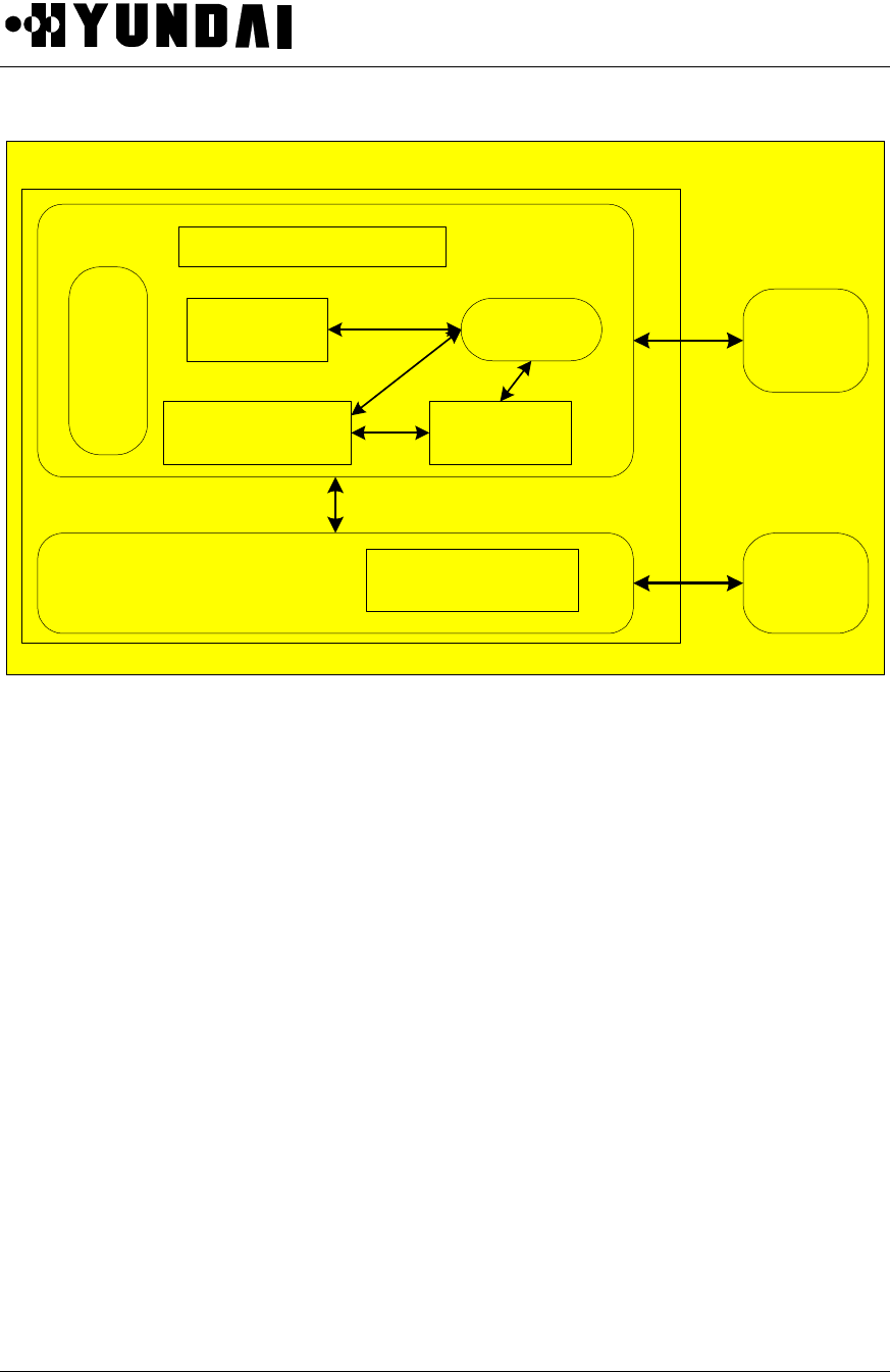
User’s Manual
PROPRIETARY & CONFIDENTIAL 5-34
CSM
Control
Baseband
Interface
CSM Management
CAI Overhead
Control
CAI Modem Driver Interrupt
Handler
Packet
Control Main
Processor
/BSC
Radio
Frequency
Units/ CAI
Foward / Reverse
Baseband Control
OS
Logical Digital Unit
Figure 5.14 software structure of DU

User’s Manual
PROPRIETARY & CONFIDENTIAL 5-35
5.5 Abbreviations
AGC Automatic Gain Control
AIU Antenna Interface Unit
BICA Base band & IF Conversion Card Assembly
BMPA BTS Main Processor Assembly
BSC Base Station Controller
BSM Base Station Manager
BTS Base station Transceiver Subsystem
CDCA CDMA Digital Channel card Assembly
COUP Coupler
CSM Cell Site Modem
D/A Digital – Analog Conversion
DNCU Down Conversion Unit
DPRAM Dual Port RAM
DU Digital Unit
EAIU Extended AIU
EMI Electro-Magnetic Interference
FA Frequency Allocation
FLASH Flash Memory
GPS Global Positioning System
HDLC High-level Data Link Controller
IF Intermediate Frequency
LED Light Emitting Diode
LNA Low Noise Amplifier
LPA Linear Power Amplifier
LPF Low Pass Filter
MMC Man-Machine Communication
MS Mobile Station
MTBF Mean Time Between Failure
PCS Personal Communication System
PS Personal Station
QPSK Quadrature Phase Shift Keying

User’s Manual
PROPRIETARY & CONFIDENTIAL 5-36
RSSI Receive Signal Strength Indicator
RRU Remote RF Unit
RF Radio Frequency
STFU Synchronized GPS Time & Frequency Unit
SYNU Synthesizer Unit
TBD To Be Determined
TCE Traffic Channel Element
TOD Time Of Day
TPTL Transmit Power Tracking Loop
UPCU Up Conversion Unit
XCVU Transceiver Unit
XVBB Transceiver Back Board
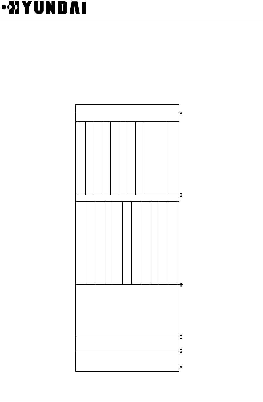
User’s Manual
PROPRIETARY & CONFIDENTIAL 6-1
Chapter 6 Micro-BTS References
6.1 Rack Configuration
6.1. 1 MBTR I (1.9GHz) in Sector (IF it is used in OMNI, SYNU-B1 is replaced with SYNU-B2)
AIDU or AIU - B1/Divider
RPU-B3
XVBB-B1
BMPA-B2
Air Baffle
359mm
314mm 170mm 50mm
S
T
F
U
-
B1
C
D
C
A
-
B
1
C
D
C
A
-
B
1
C
D
C
A
-
B
1
C
D
C
A
-
B
1
B
I
C
A
-
B
1
B
I
C
A
-
B
1
B
I
C
A
-
B
1
Blank
U
P
C
U
-
B1
L
O
D
U
-
B1
D
N
C
U
-
B1
D
N
C
U
-
B1
S
Y
N
U
-
B1
U
P
C
U
-
B1
D
N
C
U
-
B1
D
N
C
U
-
B1
U
P
C
U
-
B1
D
N
C
U
-
B1
D
N
C
U
-
B1
H
L
-
A
-
B
1
53mm
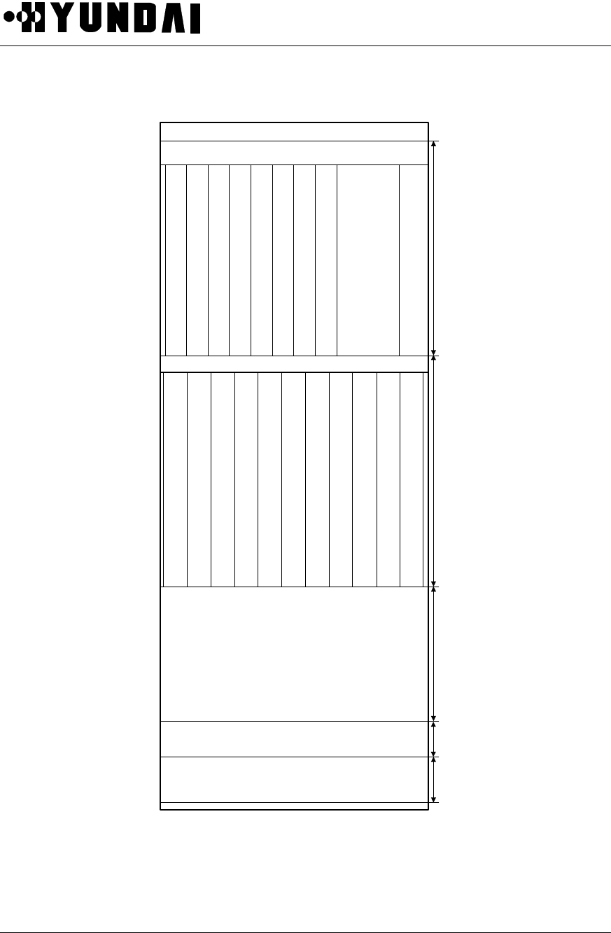
User’s Manual
PROPRIETARY & CONFIDENTIAL 6-2
6.1. 2 MBTR I (800MHz)
AIDU or AIU-B1/Arrester/Divider
RPU-B3
XVBB-B1
BMPA-B2
Air Baffle
359mm
314mm 170mm 50mm
S
T
F
U
-
B1
C
D
C
A
-
B
1
C
D
C
A
-
B
1
C
D
C
A
-
B
1
C
D
C
A
-
B
1
B
I
C
A
-
B
1
B
I
C
A
-
B
1
B
I
C
A
-
B
1
Blank
U
C
V
U
L
O
D
U
D
N
C
U
D
N
C
U
S
Y
N
U
U
C
V
U
D
N
C
U
D
N
C
U
U
C
V
U
D
N
C
U
D
N
C
U
H
L
-
A
-
B
1
53mm

User’s Manual
PROPRIETARY & CONFIDENTIAL 6-3
6.2 DIP switch & Strap
6.2.1 Summary
This section contains information about setting properly DIP switch and Strap by showing DIP switch and
Strap diagrams.
6.2.2 Purpose
This material gives an operator information about what DIP switch and Strap mean and how to set those
which are placed on PBA. It also includes some notes
6.2.3 Address Setting in Common
• Counts pin no. from left-top to left-bottom.
• Deletion of shunt means “1”, insertion of shunt means “0”.
• OFF state of DIP switch means “1” and ON does “0”
• Some DIP switches and straps do not follow the above rules so you should read this
manual carefully, especially in case of address setting.
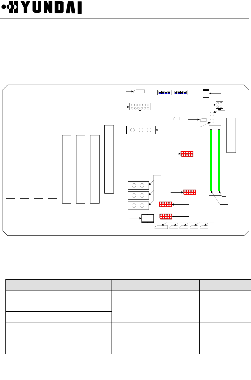
User’s Manual
PROPRIETARY & CONFIDENTIAL 6-4
6.2.4 BMPA-B2 ( BTS Main Processor Assembly – B2 )
6.2.4.1 Strapping Drawing
6.2.4.2 Setting
NO Function Normal NO Function Normal
JP3 U14 ISP Port N/A
JP4 U22 ISP Port N/A
JP6 BSAM Port N/A
SW2 ID Selecting
Number = Bit Number
On = Low
1-2 : BTS 4-5
3-5 : GCIN 0-2
6-7 : Reserved
8 : FA ID
JP7 HDLC CLK Selector 7-8 SW3
ID Selecting
Number = Bit Number
On = Low
1-4 : BSC 0-3
5-8 : BTS 0-3
S
T
F
U
48P
R
A
M
EP3
PCON1
P8
EP1
EP2
EP4
JP4
JP3
JP7
EP9
JP6
EP15
EP14
EP13
EP10
PCON2
EP8
EP12
EP7 EP6 EP5
BSAM(10P)
HDLC
CLOCK(10P)
ALARM
FPGA
(10P)
FPGA(10P)
DEBUG
(3P)
TO FA2
METRAL
STFU
PWR(4P)
BICA
TX
BICA
RX
BMPA-B1
TO
XVBB-B1
HEAT ALM 8P
DEFUALT
16MB
OPTION
A B G
B0 B1
G0 G1
A0 A1
RECTIFIER
I/F (6P)
EP11
SW3 SW2
MSB (DIP SW) LSB
10MS
B
I
C
A
G
96P
J1
B
I
C
A
B
96P
P2
B
I
C
A
A
96P
P3
C
D
C
A
0
96P
P4
C
D
C
A
2
96P
P6
C
D
C
A
1
96P
P5
C
D
C
A
3
96P
P7
DU
PWR(12P) FA2
10MS
H
L
T
A
-
B
1
96P
J1
Reset
SW
SW1
* ADDR Setting
BSC(4)+BTS(6)+GCIN(3)+0+0+FA
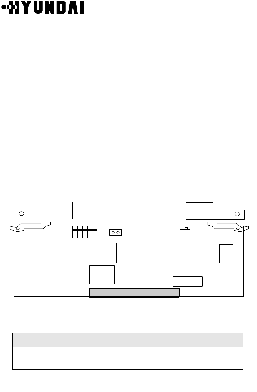
User’s Manual
PROPRIETARY & CONFIDENTIAL 6-5
6.2.5 CDCA-B1 ( CDMA Digital channel Card Assembly - B1 )
6.2.5.1 Strap Drawing
- NOT APPLICABLE.
6.2.5.2 Setting
- NOT APPLICABLE
6.2.6 BICA-B1 ( Baseband & IF Conversion card Assembly - B1 )
6.2.6.1 Strapping Drawing
TP2:
on:18lsb^2
M1
M2
U17
M3
B
I
C
A
-
6.2.6.2 Setting
No. Description
TP2 Shunt on : Received sample variance is 18-LSB^2
Shunt off : Received sample variance is 9-LSB^2
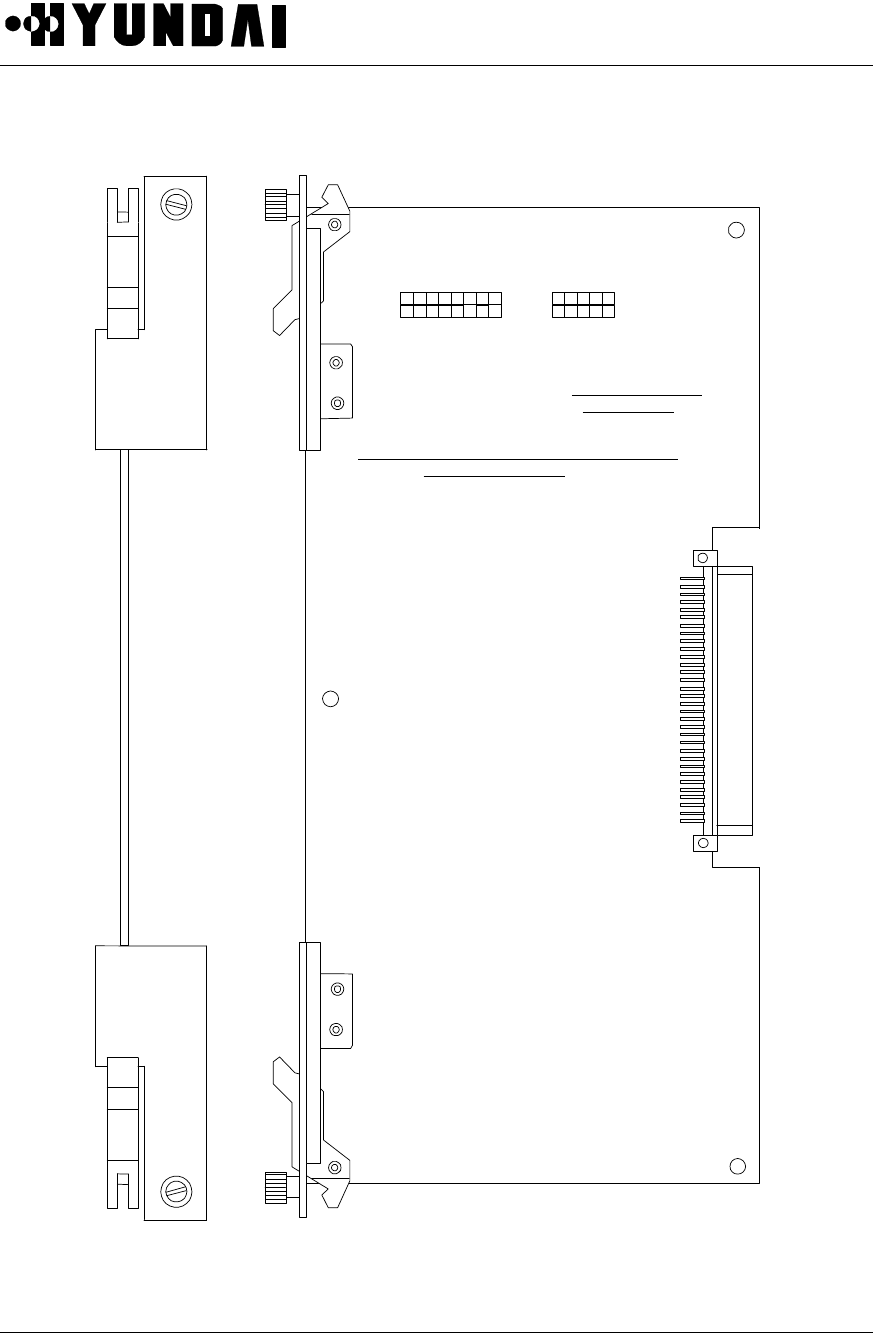
User’s Manual
PROPRIETARY & CONFIDENTIAL 6-6
6.2.7 HLTA-B1
1 2 3 4 5 6 7 8
16151413121110 9 1 2 3 4 5
10 9 8 7 6
JP1 JP2
[JP1]
Characteristics Control according to TRUNK Characteristics Control according to TRUNK
MODE & CABLE LENGTHMODE & CABLE LENGTH
<TRUNK MODE>
FUNC1,2 : RESERVED
CODE: 0(AMI), 1(B8ZS)
MODE: 0(ESF), 1(SF)
<EQUALIZER CONTROL>
LS4 LS3 LS2 LS1 PULSE GAIN
LONG 0 0 0 0 0.0dB
36dB
LONG 0 0 1 0 -7.5dB
36dB
LONG 0 1 0 0 -15.0dB
36dB
LONG 0 1 1 0 -22.5dB
36dB
LONG 0 0 0 1 0.0dB
26dB
LONG 0 0 1 1 -7.5dB
26dB
LONG 0 1 0 1 -15.0dB
26dB
LONG 0 1 1 1 -22.5dB
26dB
SHORT(133ft) 1 0 1 1
12dB
SHORT(266ft) 1 1 0 0
12dB
SHORT(399ft) 1 1 0 1
12dB
SHORT(533ft) 1 1 1 0
12dB
SHORT(655ft) 1 1 1 1
12dB
(1: JUMPER OFF, 0: JUMPER ON)
* SHORT(133ft) : Manufacturing Setting
TCK
TDO
TMS
TDI VCC
GND
GND
FUNC1
FUNC2
CODE
MODE
LS4
LS3
LS2
LS1
[JP2]
Conecting Cable for
U2 Programming
HH
LL
TT
AA
--
BB
11

User’s Manual
PROPRIETARY & CONFIDENTIAL 6-7
6.3 LED Description
6.3.1 BMP
6.3.1.1 BMPA-B2
LED ON / OFF DESCRIPTION
+5V ON(GREEN) LED OFF : +5V FAIL
RUN ON(GREEN) LED OFF : CPU FAIL
MASTER ON(GREEN) LED OFF : SLAVE
LOAD_DONE ON(GREEN) BMPA-B2 OS + AP Loading Complete
BMP_PKT ON(GREEN) LED ON : MY PACKET WITHOUT NO ERROR
6.3.1.2 HLTA-B1
LED ON / OFF DESCRIPTION
ON Trunk active (normal)
ACT OFF Trunk block (abnormal)
6.3.2 DU ( Digital Unit )
PBA LED Normal Description
LED1 OFF RED ON : PARITY ERROR
BICA-B1 LED2-1 ON(GREEN) LED OFF : +5V FAIL
LED2-2 ON(GREEN) LED OFF : +12V FAIL
LED2-3 ON(GREEN) LED OFF : -12V FAIL
LED2-4 ON/OFF BLINK
ALWAYS ON OR OFF, OR NO BLINK WITH 4-SECOND
PERIOD, ON 2 AND OFF 2 SECOND : 19.6608M AND/OR
EVEN SECOND CLOCK FAIL

User’s Manual
PROPRIETARY & CONFIDENTIAL 6-8
CDCA-B1 LED1 TOGGLE
ALWAYS ON OR OFF, OR NO BLINK WITH 4-SECOND
PERIOD, ON 2 AND OFF 2 SECOND : EVEN SECOND
INTERRUPT HANDLER RUNNING
LED2 OFF CPU RESET
6.3.3 TFU ( Time & Frequency Unit )
PBA LED Color Normal Abnormal Description
RUN GREEN ON OFF LED ON : about 17 minutes after
initial OFF
WARMUP GREEN OFF ON LED OFF : about 90 minutes after
initial OFF
GPSALM GREEN OFF ON/OFF LED ON : Tracking is not valid
Blink : Ant. is not connected
1PPSALM GREEN OFF ON
LED ON : current 1PPS output is out
of phase more than 800 nano second
from satellite 1PPS
FAULT RED OFF ON LED ON : STFU Fault
10MHz RED OFF ON LED ON : 10MHz Fault
19.6608MHz RED OFF ON LED ON : 19.6608MHz Fault
STFU
- B1
PP2S RED OFF ON LED ON : PP2S Fault
6.3.4 RPU
- Not applicable

User’s Manual
PROPRIETARY & CONFIDENTIAL 6-9
6.4 Alarm Source List
Refer to the Table 6-1 Alarm Table
Table 6-1 Alarm Table
Board Register Bit Alarm Source Name Connection
7(LSB) CDCA0_FAIL
6CDCA0_OFF
5CDCA1_FAIL
4CDCA1_OFF
3CDCA2_FAIL
2CDCA2_OFF
1CDCA3_FAIL
0
0(MSB) CDCA3_OFF
ALM_CS0(0F104040)
CDCA STATUS
7(LSB) A_BICA_OFF
6B_BICA_OFF
5G_BICA_OFF
4STFU_FAIL
3STFU_OFF
2HLTA_OFF
1
1
0(MSB)
ALM_CS1(0F104041)
BICA/STFU/TRUNK STATUS
7(LSB) A_ DNC0_OFF
6A_ DNC1_OFF
5B_ DNC0_OFF
4B_ DNC1_OFF
3G_ DNC0_OFF
2G_ DNC1_OFF
1
BMPA
2
0(MSB)
ALM CS2(0F104042)
DNCA STATUS

User’s Manual
PROPRIETARY & CONFIDENTIAL 6-10
7(LSB) A_UPC_OFF
6B_UPC_OFF
5G_UPC_OFF
4IDU_FAIL
3SYNTH_FAIL
2
1
3
0(MSB)
ALM CS3(0F104043)
UPCA/IDU/SYNTH STATUS
7(LSB) EXTERNAL_FAN_FAIL
6INTERNAL_FAN_FAIL
5
4HEATER_FAIL
3Door OPEN
2
1
4
0(MSB)
ALM CS4(0F104044)
FAN STATUS
7(LSB) Remote Door Open
6ASS1
5ASS2
4ASS3
3ASS4
2ASS5
1ASS6
5
0(MSB) ASS7
ALM CS5(0F104045)
Remote Door & RESERVED
Alarm Port #1
7(LSB) ASS8
6ASS9
5ASS10
4ASS11
3ASS12
6
2ASS13
ALM CS6(0F104046)
RESERVED Alarm Port #2
1ASS146
0(MSB) ASS15

User’s Manual
PROPRIETARY & CONFIDENTIAL 6-11
7(LSB) TX_LD
6RFA_LD
5RFB_LD
4RFG_LD
3RFIF_LD
24.95_LD
1
7
0(MSB)
PLL_RD(0F104047)
PLL STATUS

User’s Manual
PROPRIETARY & CONFIDENTIAL 6-12
6.5 Abbreviations
AIDU Active InDoor Unit
BICA Baseband & IF Conversion Card Assembly
BSC Base Station Controller
BSC CMNR BSC CoMmoN Rack
BSM Base Station Manager
BTS Base station Transceiver Subsystem
CDCA CDMA Digital Channel Card Assembly
DU Digital Unit
GPS Global Positioning System
HLTA High-Capacity Link T1 board Assembly
LNA Low-Noise Amplifier
M/WMicroWave
PCS Personal Communication System
PP2S Pulse Per 2 Second
PS Personal Station
QCELP Qualcomm Code Excited Linear Prediction
QPSK Quadrature Phase Shift Keying
RFU Radio & Frequency Unit
RS Remote Site
TOD Time Of Day
UPCU Up Conversion Unit (1900MHz)
UCVU Up Conversion Unit (800MHz)
XVBB Transceiver BackBoard