Hyundai Electronics Co HD-MIC800 Base Station Transceiver Subsystem (Micro-BTS Syst User Manual FCC cover
Hyundai Electronics Industries Co Ltd Base Station Transceiver Subsystem (Micro-BTS Syst FCC cover
UserManual.wiki
>
Hyundai Electronics Co
>
HD MIC800 User Manual
Users Manual Part 1
Navigation menu
Upload a User Manual
Namespaces
Wiki Guide
HTML
PDF
Info
Views
User Manual
Discussion / Help
Navigation
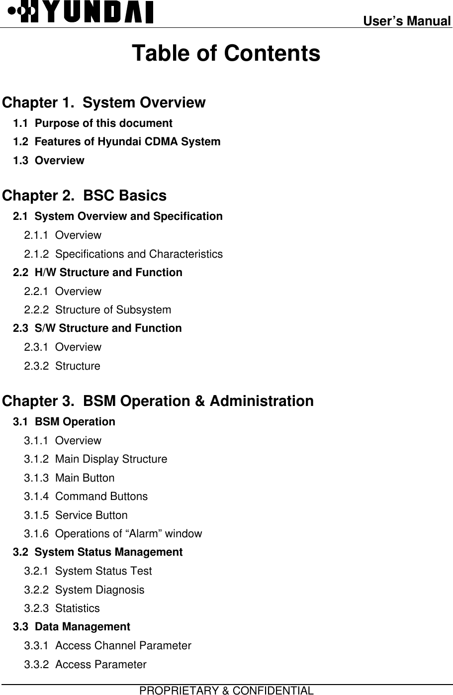
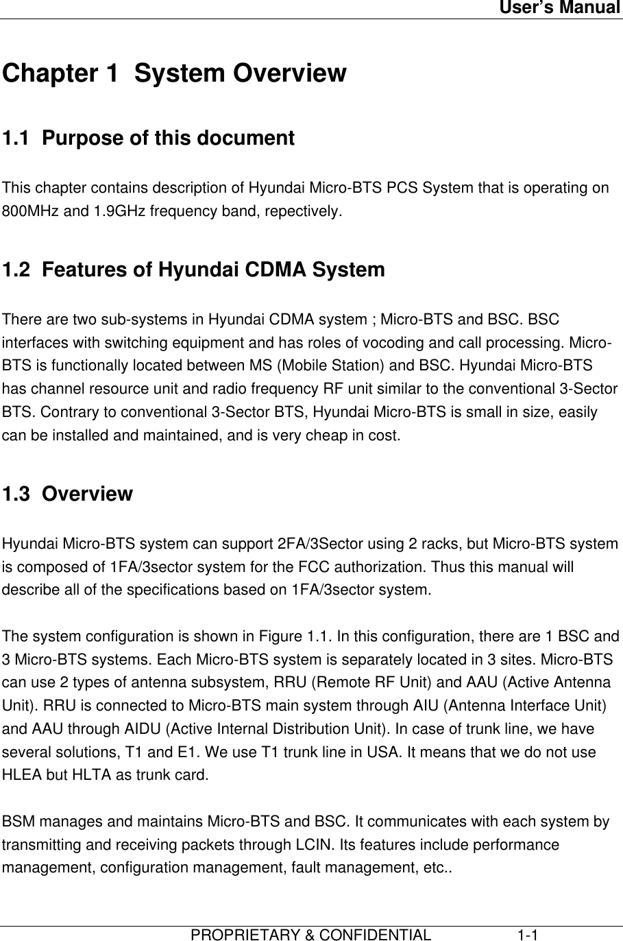
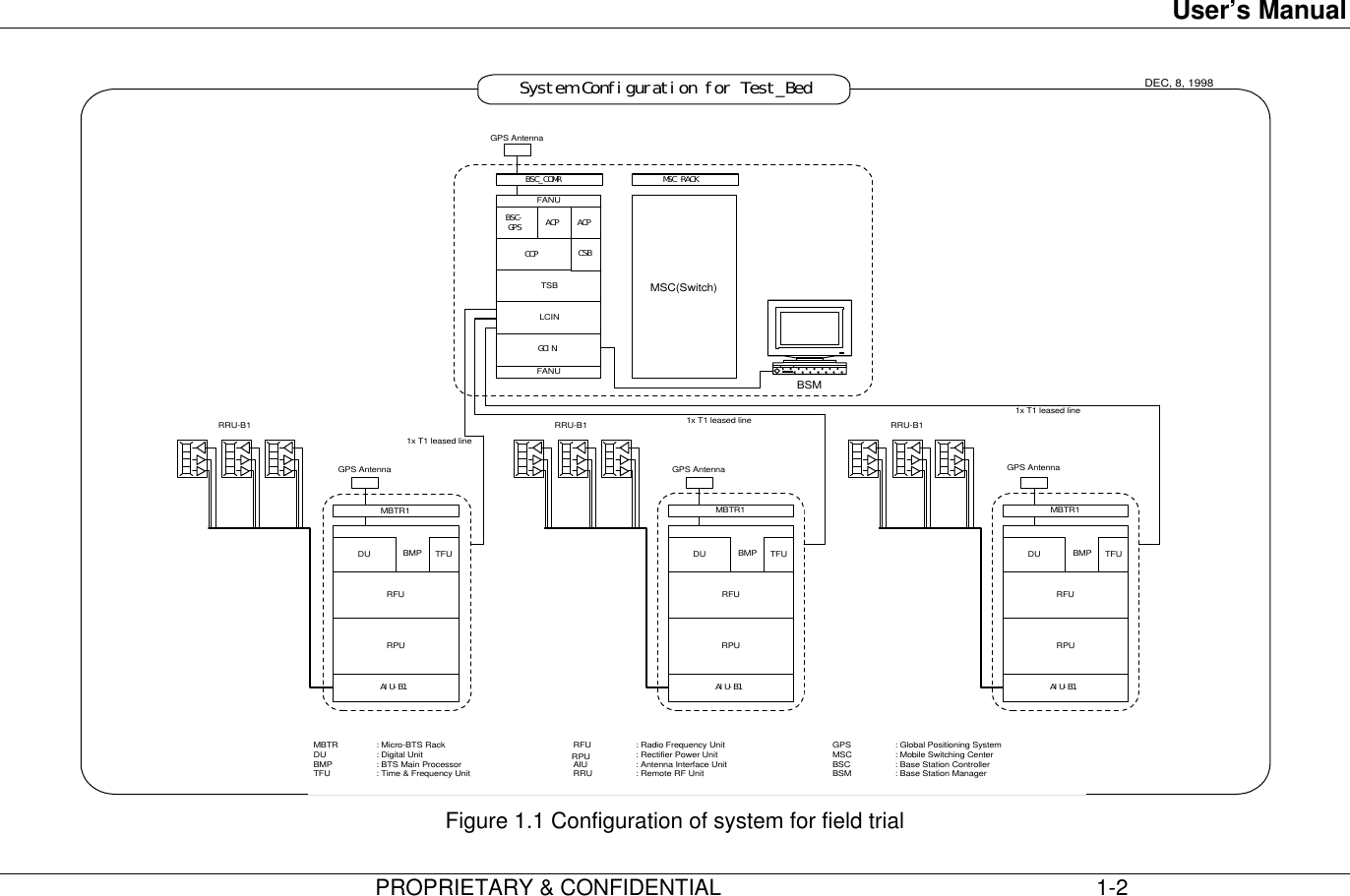
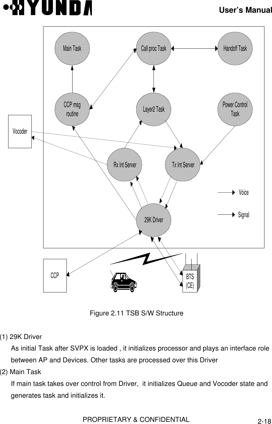
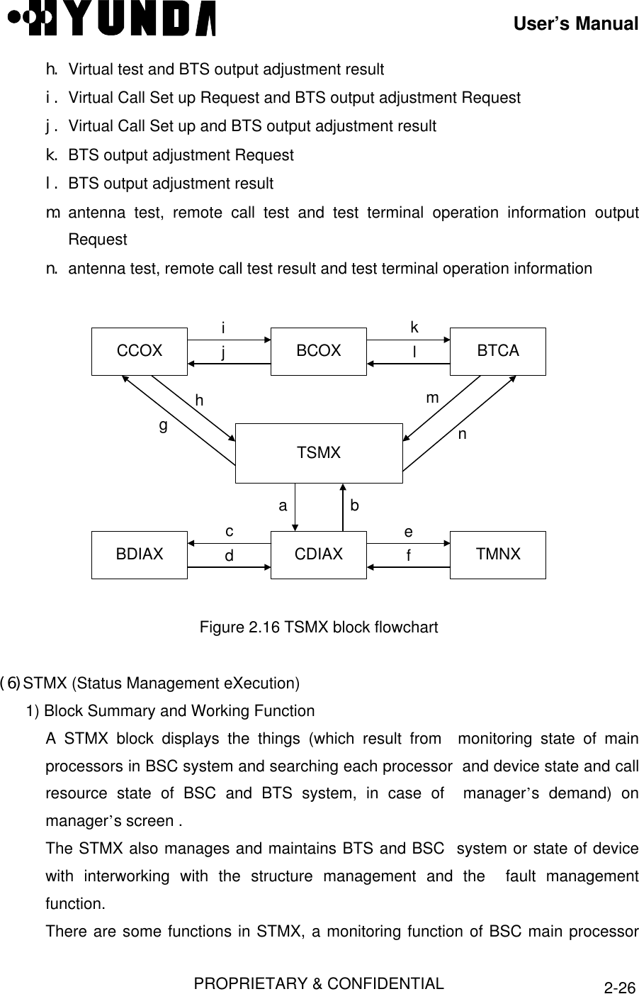
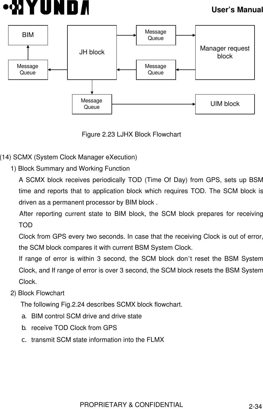
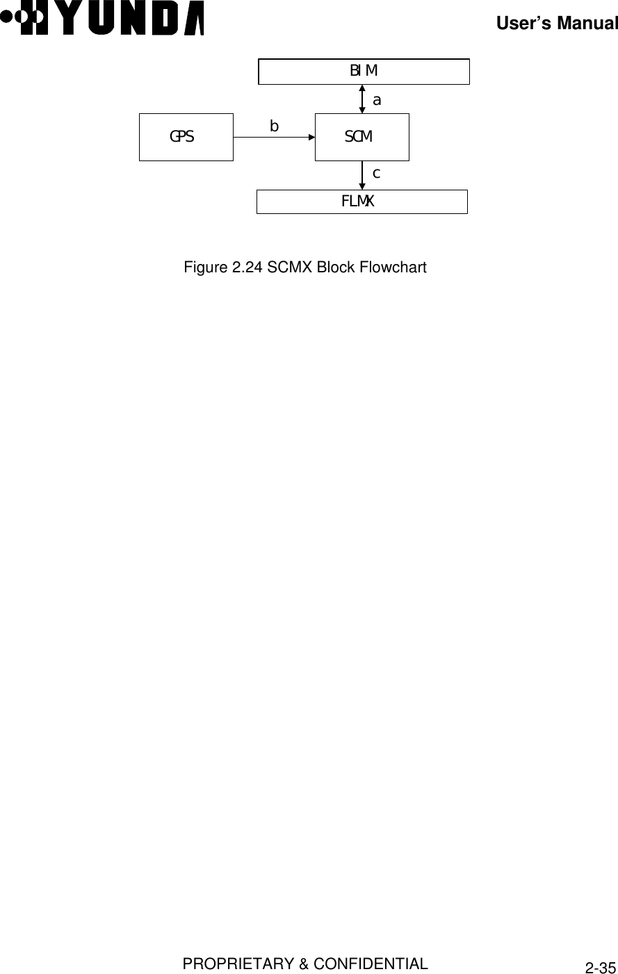
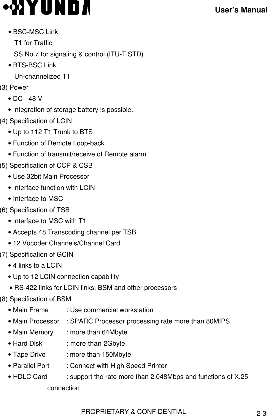
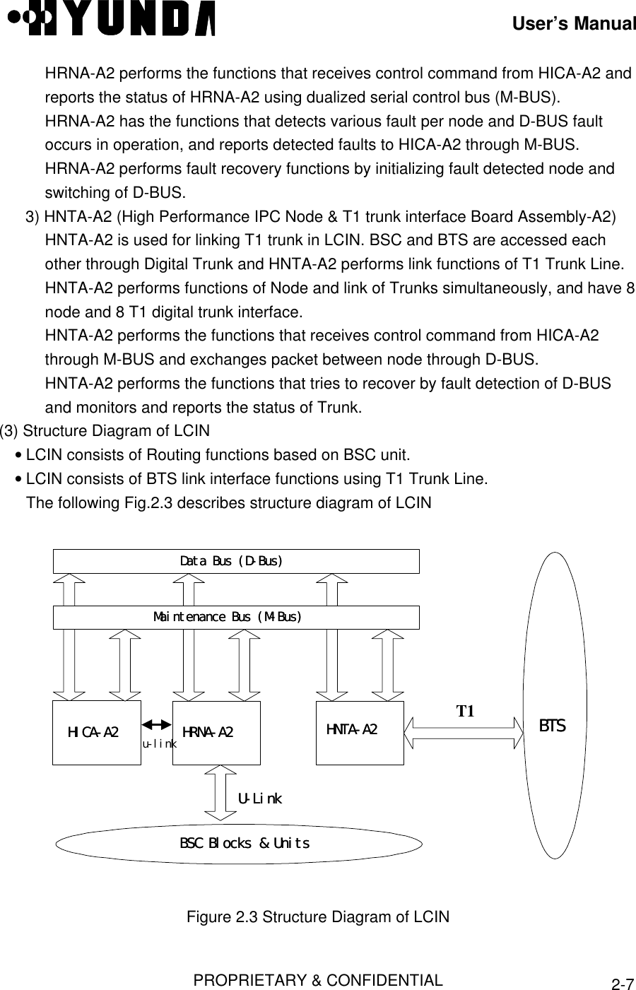
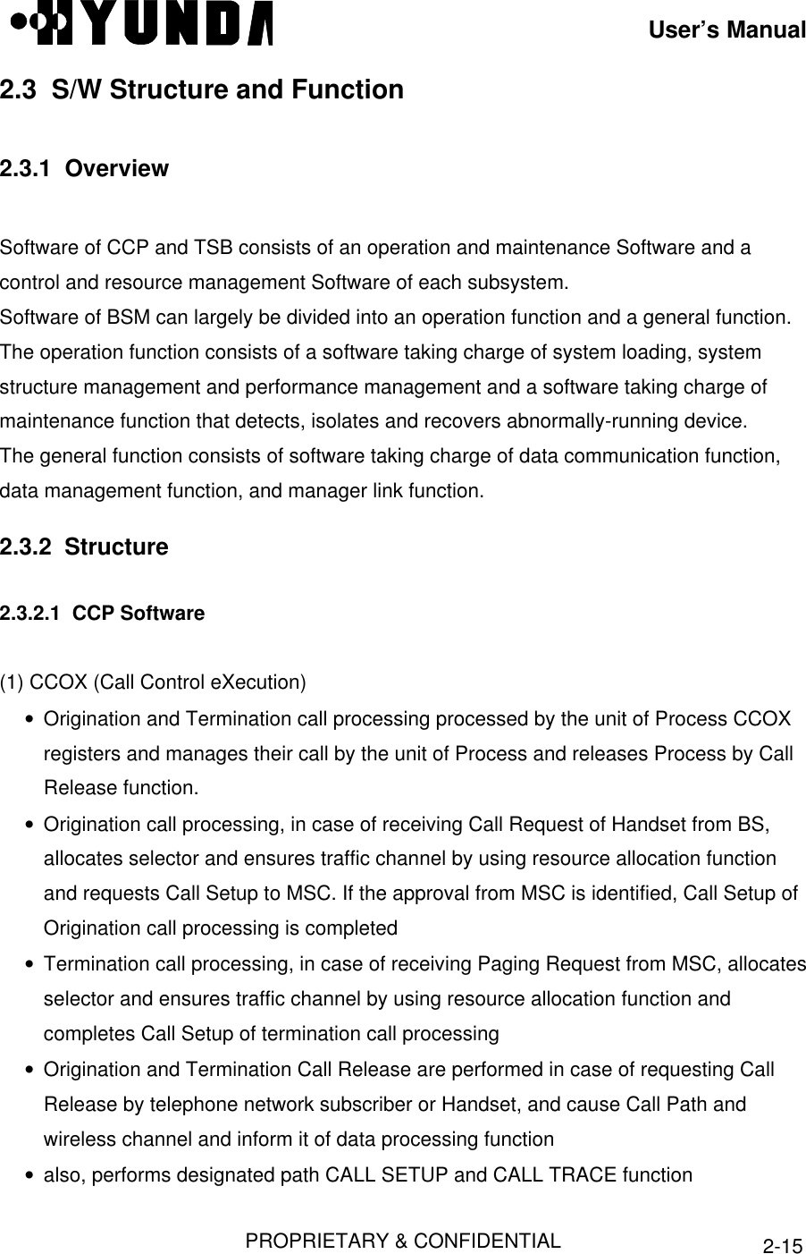
![User’s ManualPROPRIETARY & CONFIDENTIAL 2-1Chapter 2 BSC Basics2.1 System Overview and Specification2.1.1 OverviewBSC is located between MSC and BTS. It carries out a wire/wireless link control function,handoff function and transcoding function. And it is made up of a LCIN, GCIN, TSB, CCP,CSB, CKD, BSC-GPS, and BSM block. [Refer to Fig.2.1].BTS0BTS1BTS59LCINCCP CSBTSBACP CKDBTS BSC MSCBSM Others BSCT1T1T1T1T1IPC IPC IPC IPCIPCIPCIPCGCIN IPCBSC-GPSFigure 2.1 Configuration of BSCEach block does following functions.• BSM is a system used to operate the entire BSC and BTS, to manage their resources,status and configuration, and to execute the user interface, and maintenance. It consistsof a SUN Sparc Workstation and the various types of input/output devices for enhancinguser's convenience.• LCIN is a network that provides the communication paths of packet-type data betweensubsystems. LCIN routes and transmits packet data within BSC and it has trunk interfacefunction between BSC and BTS.](https://usermanual.wiki/Hyundai-Electronics-Co/HD-MIC800/User-Guide-59968-Page-8.png)
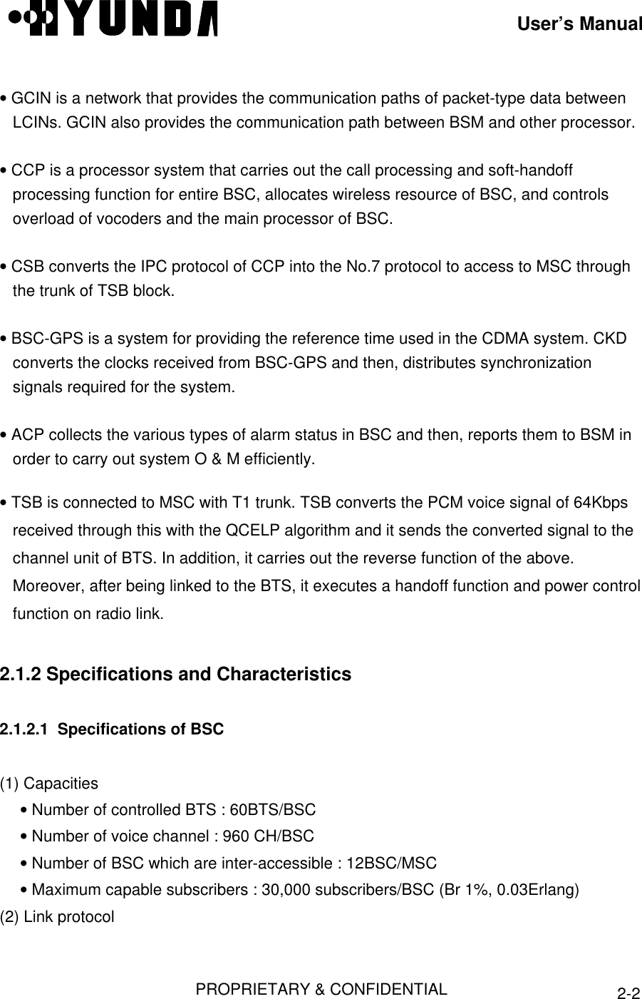
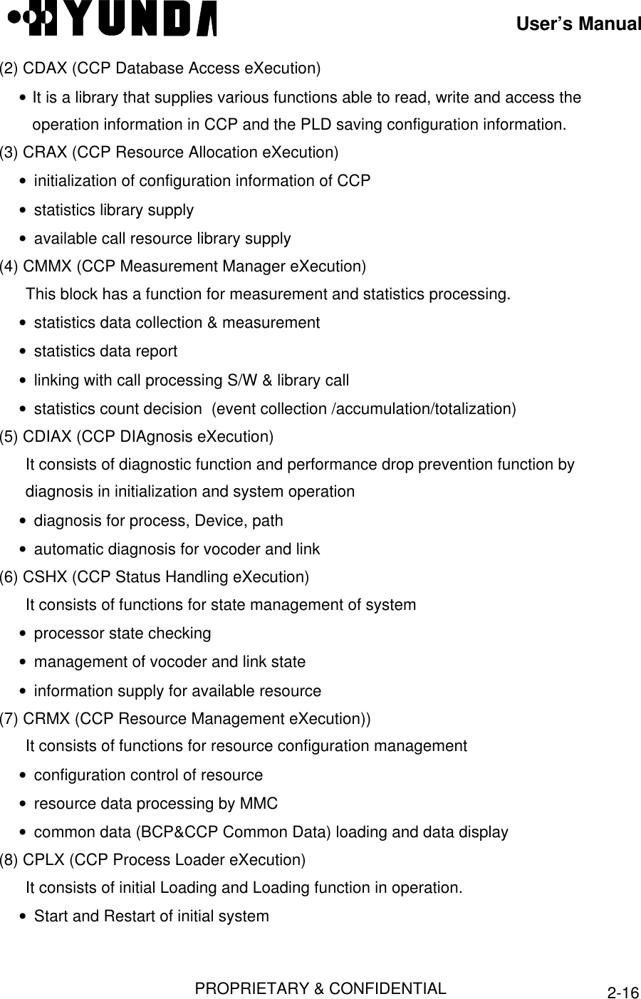
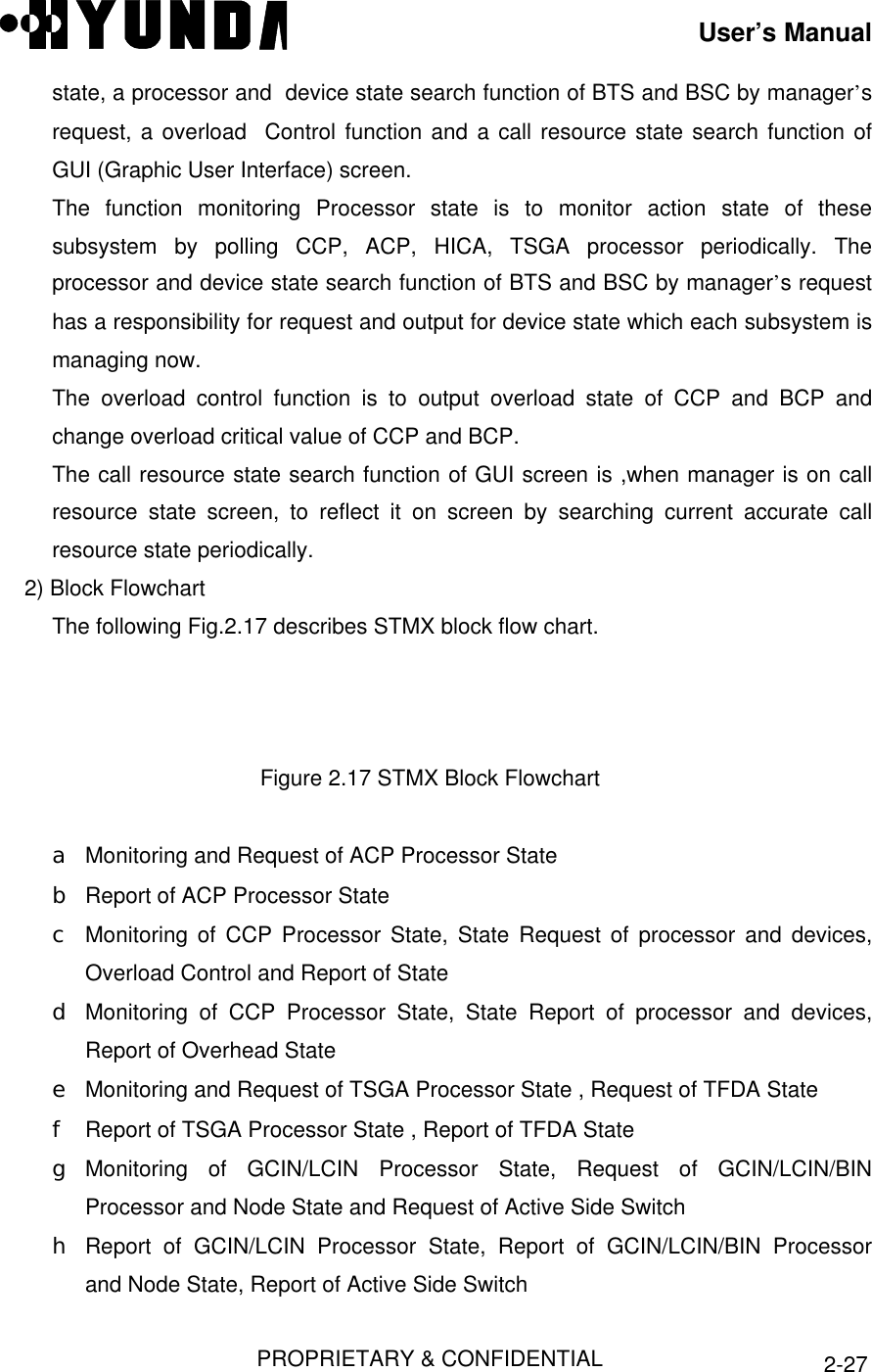
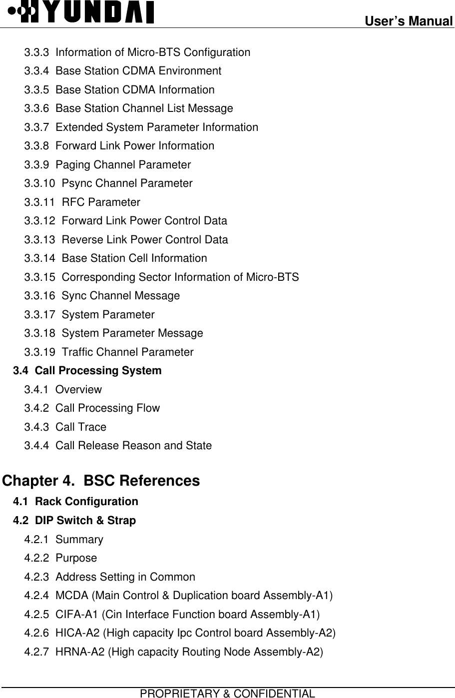
![User’s ManualPROPRIETARY & CONFIDENTIAL 2-17• Start and Restart of process• Stand-by Loading• initialization (data initialization, process initialization and state identification)2.3.2.2 Software Structure of CCPThe following Fig.2.10 describes S/W structure of CCPCCOX CRMXCDAXCSHXCDIAXCMMXCPLXCRAXPLDFigure 2.10 S/W Structure of CCP2.3.2.3 TSB S/W StructureTSB S/W (from now on, SVPX) is the S/W block driven over VSOA board, since twoProcessors exist in one board, each Processor process six channels. SVPX processestraffics and signals coming from Mobile, CE and CCP. SVPX consists of following Tasks.[Refer to Fig.2.11]](https://usermanual.wiki/Hyundai-Electronics-Co/HD-MIC800/User-Guide-59968-Page-24.png)