Hyundai IBT A927 19-inch CRT Monitor User Manual
Hyundai IBT Corp. 19-inch CRT Monitor Users Manual
Users Manual
A927
User’s Guide
P910-ENG 01.2.16 10:52 AM ∆‰¿Ã¡ˆA

P910-ENG 01.2.16 10:52 AM ∆‰¿Ã¡ˆB

U.S.A.
U.S.FEDERAL COMMUNICATIONS COMMISSION
RADIO FREQUENCY INTERFERENCE STATEMENT
INFORMATION TO THE USER
NOTE : This equipment has been tested and found to comply with the limits for a
Class B digital device pursuant to Part 15 of the FCC Rules.
These limits are designed to provide reasonable protection against harmful
interference in a residential installation.
This equipment generates, uses, and can radiate radio frequency energy and, if
not installed and used in accordance with the instructions, may cause harmful
interference to radio communications.
However, there is no guarantee that interference will not occur in a particular
i n s t a l l a t i o n .
If this equipment does cause harmful interference to radio or television reception,
which can be determined by turning the equipment off and on, the user is
encouraged to try to correct the interference by one or more of the following
m e a s u r e s :
• Reorient or relocate the receiving antenna.
• Increase the separation between the equipment and receiver.
• Connect the equipment into an outlet of a circuit different from that to which
the receiver is connected.
• Consult the dealer or an experienced radio/TV technician for assistance.
Changes or modification not expressly approved by the party responsible for
compliance could void the user's authority to operate the equipment.
Connecting of peripherals requires the use of grounded, shielded signal cables.
P910-ENG 01.2.16 10:53 AM ∆‰¿Ã¡ˆC
TCO
°Æ99
Congratulations ! You have just purchased a TCO °Æ9 9
approved and labelled product! Your choice has
provided you with a product developed for professional
use. Your purchase has also contributed to reducing the
burden on the environment and also, to the further
development of environmentally adapted electronics
p r o d u c t s .
Why do we have environmentally labelled c o m p u t e r s ?
In many countries, environmental labelling has become an established method for
encouraging the adaptation of goods and services to the environment. The main problem,
as far as computers and other electronics equipment are concerned, is that environmentally
harmful substances are used both in the products and during the manufacturing. Since it
has not been possible for the majority of electronics equipment to be recycled in a
satisfactory way, most of these potentially damaging substances sooner or later enter
N a t u r e .
There are also other characteristics of a computer, such as energy consumption
levels, that are important from the viewpoints of both the work(internal) and
natural(external) environments. Since all methods of conventional electricity generation
have a negative effect on the environment(acidic and climate-influencing emissions,
radioactive waste, etc.), it is vital to conserve energy. Electronics equipment in offices
consume an enormous amount of energy since they are often left running continuously.
What does labelling involve?
This product meets the requirements for the TCO °Æ99 scheme which provides for
international and environmental labelling of personal computers. The labelling scheme was
developed as a joint effort by the TCO (The Swedish Confederation of Professional
Employees), Naturskyddsforeningen (The Swedish Society for Nature Conservation) and
NUTEK (The National Board for Industrial and Technical Development in Sweden).
The requirements cover a wide range of issues: environment, ergonomics, usability, emission
of electrical and magnetic fields, energy consumption and electrical and fire safety.
The environmental demands concern restrictions on the presence and use of heavy metals,
brominated and chlorinated flame retardants, CFCs (freons) and chlorinated solvents,
among other things. The product must be prepared for recycling and the manufacturer is
obliged to have an environmental plan which must be adhered to in each country where the
company implements its operational policy.
The energy requirements include a demand that the computer and/or display, after a
certain period of inactivity, shall reduce its power consumption to a lower level in one or
more stages. The length of time to reactivate the computer shall be reasonable for the user.
Labelled products must meet strict environmental demands, for example, in respect of the
reduction of electric and magnetic fields, physical and visual ergonomics and good
u s a b i l i t y .
On the back page of this folder, you will find a brief summary of the
environmental requirements met by this product. The complete environmental criteria
document may be ordered from:
TCO Development Unit
S-114 94 Stockholm
S w e d e n
Fax: +46 8 782 92 07
Email (Internet) : development @ tco.se
P910-ENG 01.2.16 10:53 AM ∆‰¿Ã¡ˆD

Current information regarding TCO °Æ99 approved and labelled products may also be
obtained via the Internet, using the address:
h t t p : / / w w w . t c o - i n f o . c o m /
TCO °Æ99 is a co-operative project between T C O (The Swedish Confederation of
Professional Employees), N a t u r s k y d d s f o r e n i n g e n (The Swedish Society for Nature
Conservation) and N U T E K(The National Board for Industrial and Technical Development
in Sweden).
Environmental Requirements
Brominated flame retardants
Brominated flame retardants are present in printed wiring boards, cables, wires, casings
and housings. In turn, they delay the spread of fire. Up to thirty percent of the plastic in a
computer casing can consist of flame retardant substances. These are related to another
group of environmental toxins, PWBs, which are suspected to give rise to similar harm,
including reproductive damage in fish eating birds and mammals, due to the bio-
accumulative processes. Flame retardants have been found in human blood and researchers
fear that disturbances in foetus development may occur.
TCO °Æ99 demand requires that plastic components weighing more than 25 grams must not contain
organically bound chlorine and bromine.
L e a d * *
Lead can be found in picture tubes, display screens; solders and capacitors. Lead
damages the nervous system and in higher doses, causes lead poisoning.
TCO °Æ99 requirement permits the inclusion of lead since no replacement has yet been developed.
C a d m i u m * *
Cadmium is present in rechargeable batteries and in the colour generating layers of certain
computer displays. Cadmium damages the nervous system and is toxic in high doses.
TCO °Æ99 requirement states that batteries may not contain more than 25 ppm (parts per million) of
cadmium. The colour-generating layers of display screens must not contain any cadmium.
M e r c u r y * *
Mercury is sometimes found in batteries, relays and switches. Mercury damages the
nervous system and is toxic in high doses.
TCO °Æ99 requirement states that batteries may not contain more than 25 ppm (parts per million) of
mercury. It also demands that no mercury is present in any of the electrical or electronics
components concerned with the display unit.
CFCs (freons)
CFCs (freons) are sometimes used for washing printed circuit boards and in the
manufacturing of expanded foam for packaging. CFCs break down ozone and thereby
damage the ozone layer in the stratosphere, causing increased reception on Earth of
ultraviolet light with consequent increased risks of skin cancer (malignant melanoma).
The relevant TCO °Æ99 requirement: Neither CFCs nor HCFCs may be used during the
manufacturing of the product or its packaging.
* Bio-accumulative is defined as substances which accumulate within living organisms
* * Lead, Cadmium and Mercury are heavy metals which are Bio-accumulative.
P910-ENG 01.2.16 10:53 AM ∆‰¿Ã¡ˆE
°·E N G L I S H
Please check your power cord before installation if it is UL listed one.
°·F R A N Ç A I S
Veuillez vérifier que votre cordon d'alimentation soit homologué UL avant
l ' i n s t a l l a t i o n .
°·I T A L I A N O
Prima di installare controllare che il cavo di alimentazione sia approvato UL.
°·D E U T S C H
Bitte prüfen Sie vor der Installation des Netzkabels, ob es in der UL-Liste
aufgeführt ist.
°·E S P A Ñ O L
Compruebe el cable de potencia antes de la instalación si es uno de la lista
U L .
P910-ENG 01.2.16 10:53 AM ∆‰¿Ã¡ˆF
P910-ENG 01.2.16 10:53 AM ∆‰¿Ã¡ˆG
C o n t e n t s
I n t r oduction . . . . . . . . . . . . . . . . . . . . . . . . . . . . . . . . . . . . . . . . . . . . . . . . . . . . . . . . . . . . . . . . . . . . . . . . . . . . . . . . . . . . . . . . 1
Safety Information . . . . . . . . . . . . . . . . . . . . . . . . . . . . . . . . . . . . . . . . . . . . . . . . . . . . . . . . . . . . . . . . . . . . . . . . . . . . . 1
Installing the monitor . . . . . . . . . . . . . . . . . . . . . . . . . . . . . . . . . . . . . . . . . . . . . . . . . . . . . . . . . . . . . . . . . . . . . . . 2
Packing List . . . . . . . . . . . . . . . . . . . . . . . . . . . . . . . . . . . . . . . . . . . . . . . . . . . . . . . . . . . . . . . . . . . . . . . . . . . . . . . . . . . . . . . . . . . . . . . . . . . . . . . . . . 2
Fastening the swivel and tilt base . . . . . . . . . . . . . . . . . . . . . . . . . . . . . . . . . . . . . . . . . . . . . . . . . . . . . . . . . . . . . . . . . . . . . 3
Selecting a suitable location . . . . . . . . . . . . . . . . . . . . . . . . . . . . . . . . . . . . . . . . . . . . . . . . . . . . . . . . . . . . . . . . . . . . . . . . . . . . . . . 3
Connecting the monitor . . . . . . . . . . . . . . . . . . . . . . . . . . . . . . . . . . . . . . . . . . . . . . . . . . . . . . . . . . . . . . . . . . . . . . . . . . . . . . . . . . . . . . 4
Setting the refresh rate . . . . . . . . . . . . . . . . . . . . . . . . . . . . . . . . . . . . . . . . . . . . . . . . . . . . . . . . . . . . . . . . . . . . . . . . . . . . . . . . . . . . . . . . 6
Preset Timing Table . . . . . . . . . . . . . . . . . . . . . . . . . . . . . . . . . . . . . . . . . . . . . . . . . . . . . . . . . . . . . . . . . . . . . . . . . . . . . . . . . . . . . . . . . . . . .6
Adjusting the picture. . . . . . . . . . . . . . . . . . . . . . . . . . . . . . . . . . . . . . . . . . . . . . . . . . . . . . . . . . . . . . . . . . . . . . . . . . 7
Using the On Screen Display . . . . . . . . . . . . . . . . . . . . . . . . . . . . . . . . . . . . . . . . . . . . . . . . . . . . . . . . . . . . . . . . . . . . . . . 7
OSD Adjustments .. . . . . . . . . . . . . . . . . . . . . . . . . . . . . . . . . . . . . . . . . . . . . . . . . . . . . . . . . . . . . . . . . . . . . . . . . . . . . . . . . . . . . . . . . . . . . . . 8
Display power management. . . . . . . . . . . . . . . . . . . . . . . . . . . . . . . . . . . . . . . . . . . . . . . . . . . . . . . . . . . . . . . . .1 1
Reducing power consumption . . . . . . . . . . . . . . . . . . . . . . . . . . . . . . . . . . . . . . . . . . . . . . . . . . . . . . . . . . . . . . . . . . . . . . . . . .1 1
Troubleshooting . . . . . . . . . . . . . . . . . . . . . . . . . . . . . . . . . . . . . . . . . . . . . . . . . . . . . . . . . . . . . . . . . . . . . . . . . . . . . . . .1 2
Contacting service . . . . . . . . . . . . . . . . . . . . . . . . . . . . . . . . . . . . . . . . . . . . . . . . . . . . . . . . . . . . . . . . . . . . . . . . . . . . . . . . . . . . . . . . . . . . . .1 3
Specifications . . . . . . . . . . . . . . . . . . . . . . . . . . . . . . . . . . . . . . . . . . . . . . . . . . . . . . . . . . . . . . . . . . . . . . . . . . . . . . . . . . . . . . . . . . . . 1 4
P910-ENG 01.2.16 10:53 AM ∆‰¿Ã¡ˆH
1
I n t ro d u c t i o n
This manual contains instructions for installing and operating A927.
A927 is a highly ergonomic color display unit;
• 19” diagonal (18” viewable) 0.26mm dot pitch CDT
• Supporting high screen refresh rates and full scan flicker-free picture quality
• With On Screen Display menus for user control
• 100-240V AC input voltage
• VESA DPMS (Display Power Management Signaling)
• VESA DDC1/2B compatibility
Safety Infor m a t i o n
When you set up and use your display unit, follow the safety instructions below.
• Do not use the display unit in humid environments like bathrooms, damp cellars,
swimming pools, etc.
• This equipment must be connected to an earthed outlet which is close to the
display unit and accessible in case you need to disconnect the display.
• Do not connect an extension cord.
• Never insert objects into the openings on the outside of the device as you can
come into contact with live electrical components. This can cause fire or give
strong electrical shocks.
• Slots in the cabinet are provided for ventilation. Do not block the ventilation slots
in the display unit cabinet.
• Do not under any circumstances open the display unit cabinet.
Cleaning and Maintenance
• To avoid risk of electric shock, do not disassemble the display unit cabinet.
The unit is not user-serviceable. Remember to unplug the display unit from the
power outlet before cleaning.
• Do not use alcohol (methyl, ethyl or isopropyl) or any strong dissolvent. Do not
use thinner or benzene, abrasive cleaners or compressed air.
• Do not wipe the screen with a cloth or sponge that could scratch the surface.
• To clean your antistatic screen, use water and a special microfiber screen cleaning
tissue used in optical lens cleaning, or lightly dampen a soft, clean cloth with
water or a mild detergent.
• To clean display unit cabinet, use a cloth lightly dampended with a mild
d e t e r g e n t .
• During the transportation of the monitor, the swivel base has to be removed in
every case.
P910-ENG 01.2.16 10:53 AM ∆‰¿Ã¡ˆ1
User's Guide
2
Installing the monitor
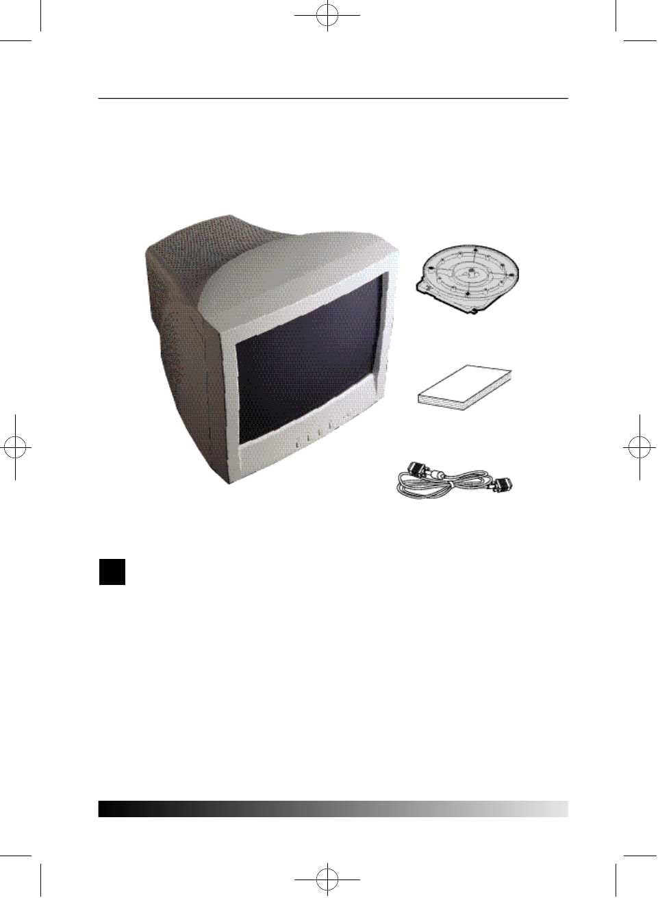
Packing List
The following items should be found in the packaging.
Above power cord can be changed upon different voltage areas. Please contact
your dealer if anything is missing or damaged.
Signal Cable
User's Guide
19” colour monitor
Tilt and Swivel
!
P910-ENG 01.2.16 10:53 AM ∆‰¿Ã¡ˆ2
3
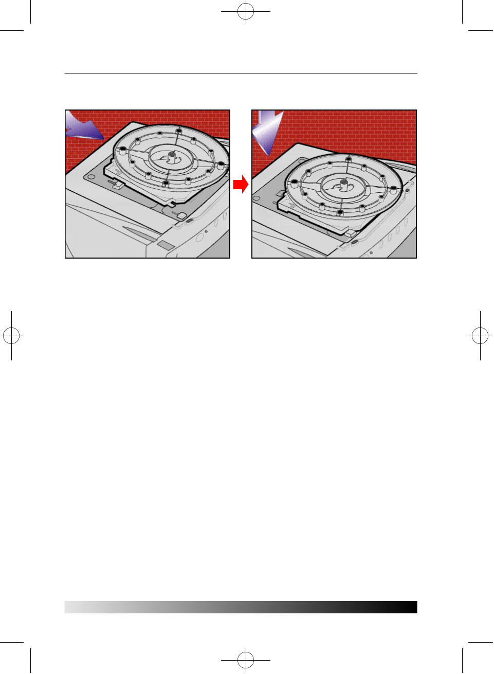
Fastening the swivel and tilt base
• Place the base against the bottom of the monitor so that the base fasteners are
aligned with appropriate slots.
• Push the base towards the front of the monitor until the latch locks into position.
Selecting a suitable location
• Place the monitor at least 30cm from other electrical or heat-emitting equipment
and allow at least 10cm on each side for ventilation.
• Place the monitor in a position where no light shines directly onto or is reflected
on the screen.
• To reduce eye strain, avoid installing the display unit against a bright background
such as a window.
• Position the monitor so that the top of the screen is no higher than eye level.
• Position the monitor directly in front of you at a comfortable reading distance
(around 45 to 90cm)
P910-ENG 01.2.16 10:53 AM ∆‰¿Ã¡ˆ3
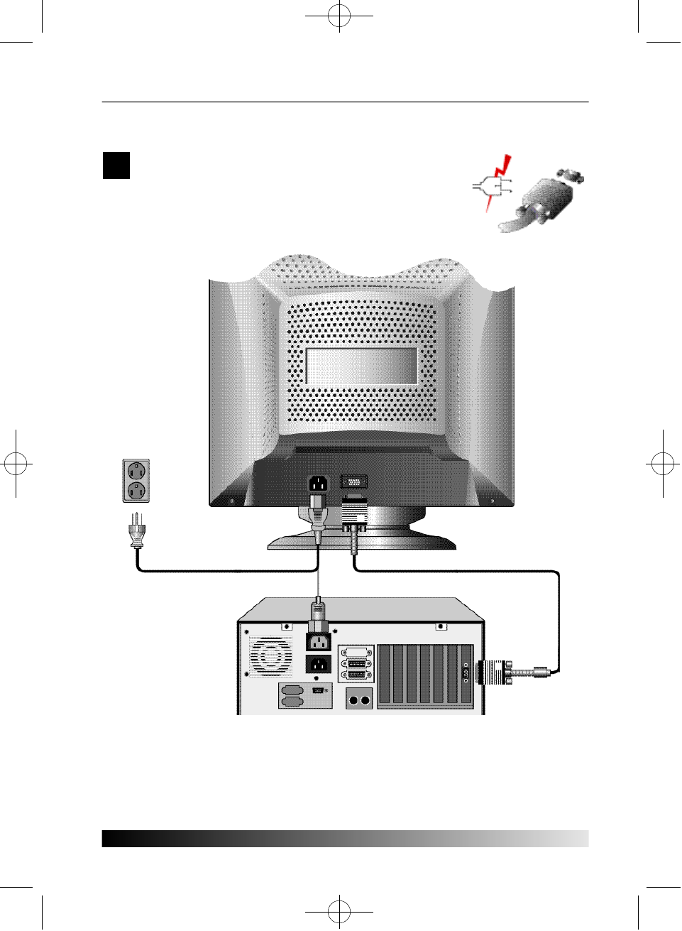
Connecting the monitor
Before you start cabling your monitor, check that the
power is off on all units. To avoid any possibility of
electric shock, always connect your equipment to
properly earthed outlets.
User's Guide
4
!
P910-ENG 01.2.16 10:53 AM ∆‰¿Ã¡ˆ4
1. Insert the 15-pin signal cable connector to the VGA connection on your computer
and screw it down.
2. Plug the display unit’s power cable first to the back of the display unit.
3. T h e nplug the power cable to a 100V - 240V earthed electrical outlet or to the
system unit, if it has an outlet for the display power cable.
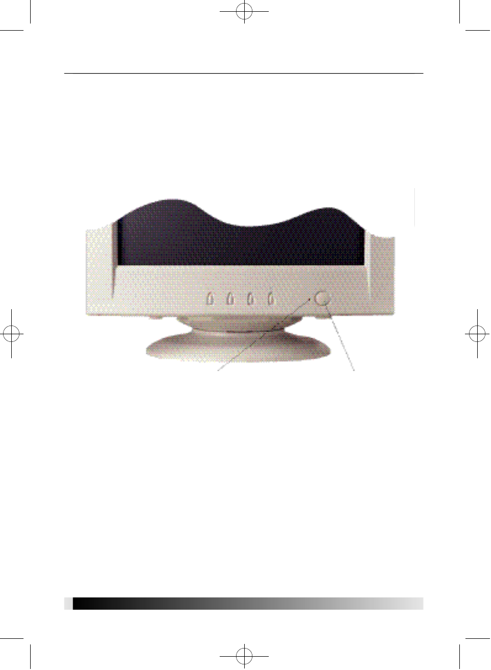
4. Turn on the display unit using the power switch and check that the power LED is
on. If not, repeat steps 2, 3 and 4 or refer to the T r o u b l e s h o o t i n gsection of this
g u i d e .
5. Turn on the power to the computer. The picture will appear within about 15
seconds. Adjust the picture to obtain optimum picture quality. See the section
Adjusting the picturein this guide for more information.
55
Power SwitchPower LED
P910-ENG 01.2.16 10:53 AM ∆‰¿Ã¡ˆ5
User's Guide
6
Setting the refresh rate
Follow the instructions below to set your refresh rate in Windows 98.
1. Go to the configuration window (Start-Settings-Configuration window).
2. Double click on the ‘Display’ icon.
3. Click on the ‘Settings’ tab.
4. Click on the ‘Advanced’ button.
5. Click on ‘Adapter’ and select 85Hz from the list.
6. Click on ‘Apply’ to accept the selected value.
The recommended setting is a resolution of 1280x1024(1600x1200) and a refresh
rate of 85Hz(75Hz).
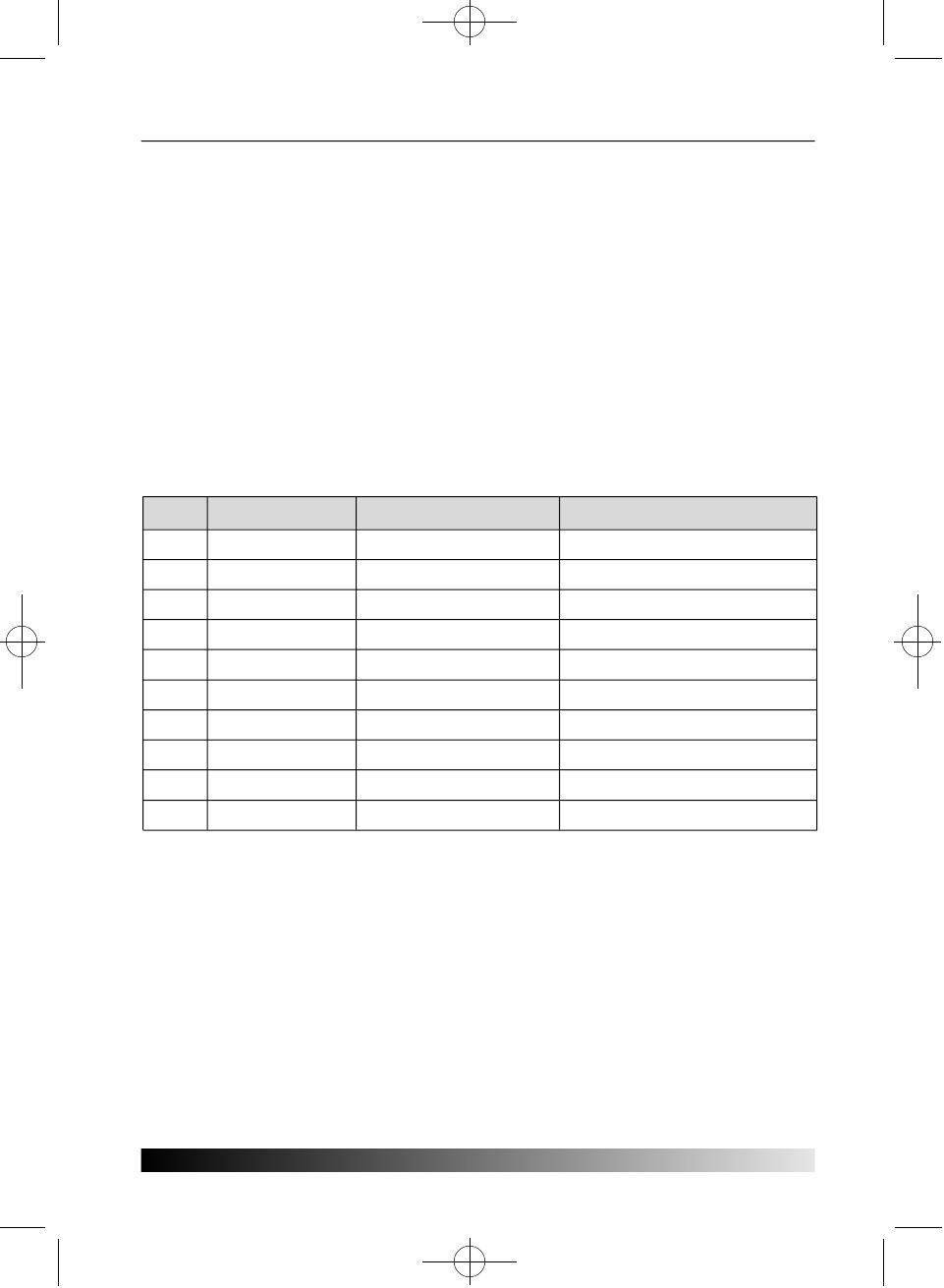
Preset Timing Table
N o .
1
2
3
4
5
6
7
8
9
1 0
R e s o l u t i o n
720 x 400
640 x 480
640 x 480
800 x 600
1152 x 864
1024 x 768
1024 x 768
1280 x 1024
1280 x 1024
1600 x 1200
Horizontal Frequency
31.5 KHz
31.5 KHz
63.7 KHz
53.7 KHz
67.5 KHz
68.7 KHz
81.8 KHz
79.9 KHz
91.1 KHz
93.8 KHz
Refresh rate
70 Hz
60 Hz
120 Hz
85 Hz
75 Hz
85 Hz
100 Hz
75 Hz
85 Hz
75 Hz
P910-ENG 01.2.16 10:53 AM ∆‰¿Ã¡ˆ6
7
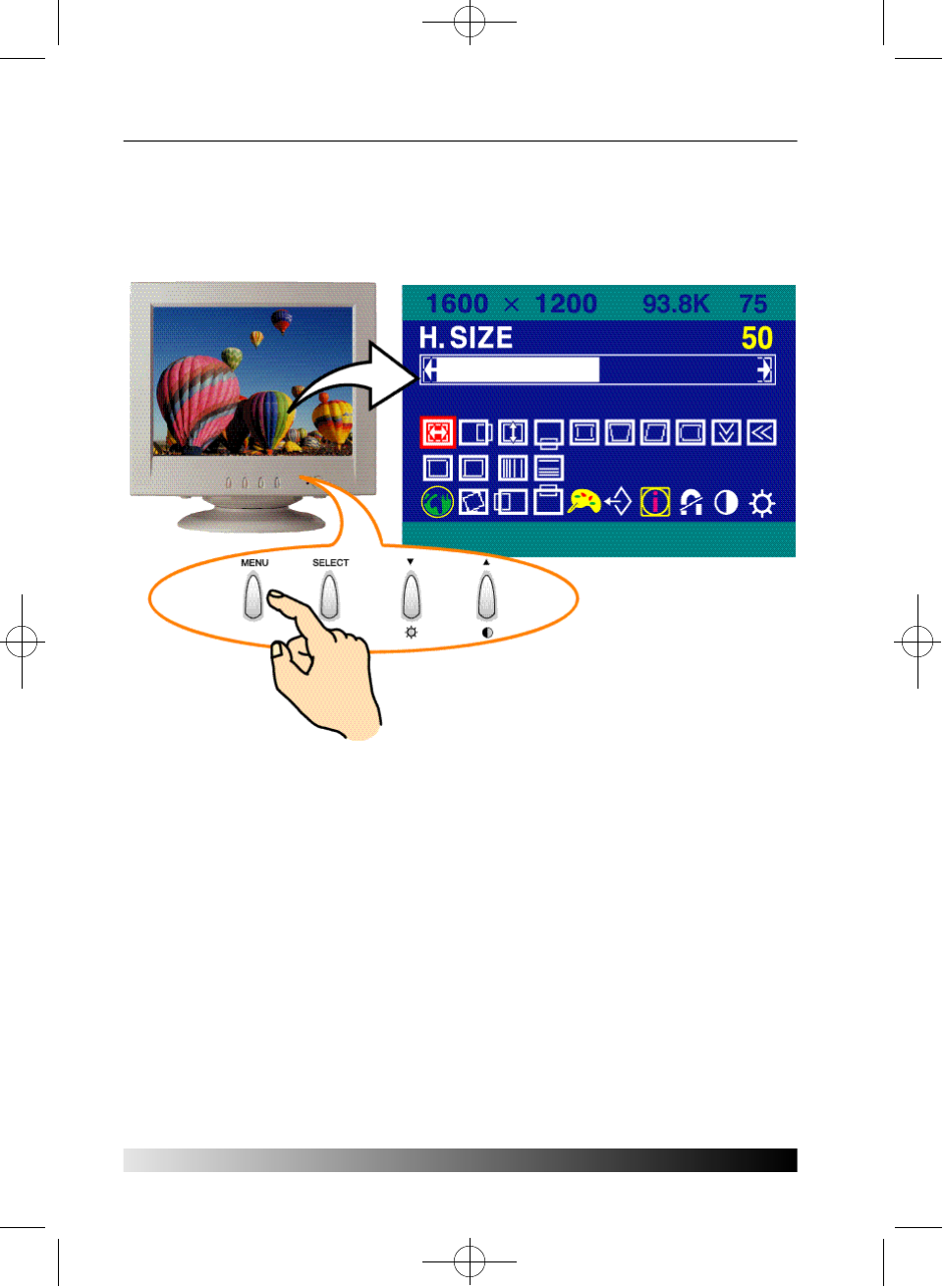
Adjusting the picture
You can adjust the screen display by using the buttons located below the screen.
Using the On Screen Display
1. Push the MENU button to call the OSD to the screen. The resolution and frequency
are displayed at the top of the menu box for your information.
2. Push the °„or °Âbutton to choose the item you want to adjust. The selected
item is highlighted.
3. Push the SELECT button to adjust the highlighted item.
4. Use the °„or °Âbutton to adjust the selection.
5. Push the MENU button to return to the previous menu if you are in a submenu.
6. The display unit automatically saves the new settings in 3 to 4 seconds after your
last adjustments and the menu disappears. You can also push the MENU button to
make the menu disappear.
Direct access buttons
P910-ENG 01.2.16 10:53 AM ∆‰¿Ã¡ˆ7
User's Guide
8
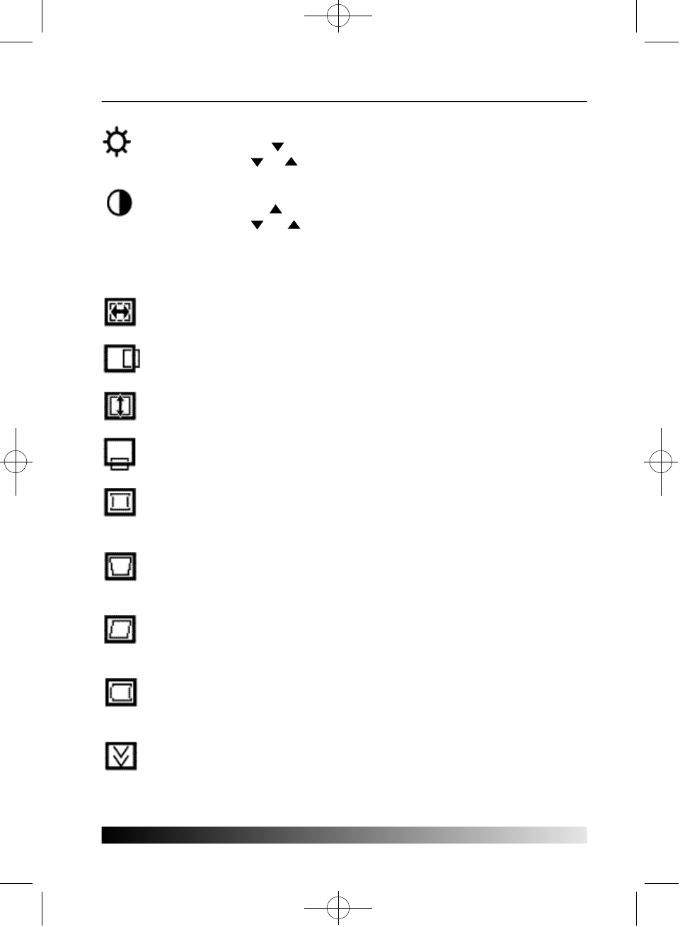
BRIGHTNESS
Use the button to select the brightness adjustment.
Adjust with or b u t t o n .
CONTRAST
Use the button to select the contrast adjustment.
Adjust with or b u t t o n .
OSD Adjustments
The OSD adjustments available to you are listed below.
H. SIZE
Adjusts the horizontal size of the entire screen image.
H. POSITION
Adjusts the horizontal position of the entire screen image.
V. SIZE
Adjusts the vertical size of the entire screen image.
V. POSITION
Adjusts the vertical position of the entire screen image.
P I N C U S H I O N
If the vertical sides of the picture curve in or bulge out, you can correct
the pincushion distortion by using this adjustment.
T R A P E Z O I D
If the picture is wider at the top or at the bottom, you can correct the
trapezoid distortion by using this adjustment.
P A R A L L E L
If the sides of the screen image are tilted, you can correct the parallel
distortion by using this adjustment.
PIN BALANCE
If the sides of the picture are bowed to the right or to the left, you can
correct the pincushion balance by using this adjustment.
V. MOIRE
Clears vertical moire if a series of concentric circles or arcs appear on
your screen.
P910-ENG 01.2.16 10:53 AM ∆‰¿Ã¡ˆ8
9
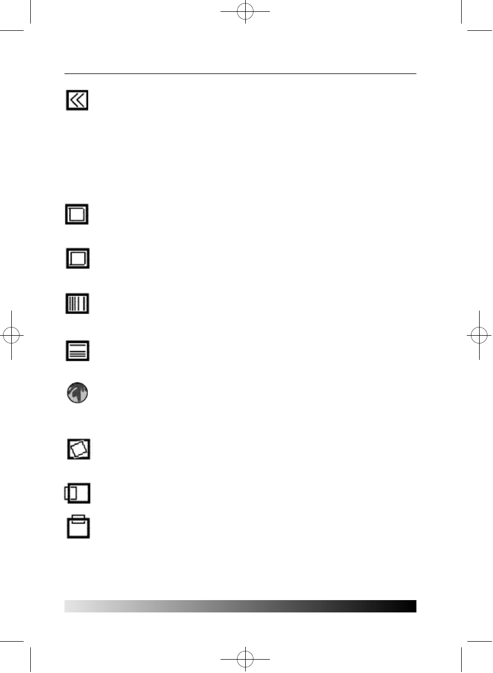
H. MOIRE
Clears horizontal moire if a series of concentric circles or arcs appear on
your screen.
Moire is an interference pattern that makes the screen seem to have
faint lines. A picture that is rasterised or consists of (small) repeating
figures is sensitive to moire interference. Strong colors are also liable to
intensify moire.
The moire pattern on the screen does not affect the printout of the
i m a g e .
TOP CORNER
If the top corner sides of the picture curve in or bulge out, you can
correct the top corner distortion by using this adjustment.
BOTTOM CORNER
If the bottom correct sides of the picture curve in or bulge out, you can
correct the bottom corner distortion by using this adjustment.
H. LINEARITY
If either left or right side of the picture is out of proportion to the other,
you can correct horizontal linearity by using this adjustment.
V. LINEARITY
If top and bottom side of the picture is out of proportion to the center
area, you can correct vertical linearity by using this adjustment.
L A N G U A G E
You can select the language in which adjustment menus are displayed.
The following languages are available; English, French, German, Italian,
Spanish, Swedish, Finnish, Danish and Portuguese.
R O T A T I O N
If the entire screen image is tilted, you can correct the distortion by
using this adjustment.
OSD H. POSITION
Adjusts the OSD menu’s horizontal position on the screen.
OSD V. POSITION
Adjusts the OSD menu’s vertical position on the screen.
P910-ENG 01.2.16 10:53 AM ∆‰¿Ã¡ˆ9
User's Guide
1 0
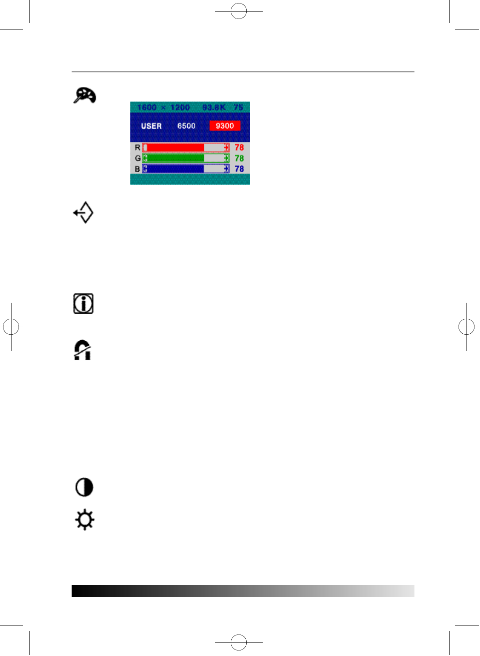
COLOR CONTROL Color temperature affects the tint of the
image. With lower color temperatures
the image turns reddish and with
higher temperatures bluish.
There are three color settings available:
9300K, 6500K or USER. With the USER
setting you can set individual values for
red, green and blue.
R E C A L L
If you operate your display unit in a factory preset mode, this function
deletes adjustments you made for size, position and shape, and
restores the properties which have been set in the factory. If you
operate your display unit in a user mode, this function has no effect
except that the contrast will be reset to the maximum value and the
brightness to the cut-off level.
I N F O R M A T I O N
Information shows horizontal and vertical sync polarity of current
timing set.
D E G A U S S
External magnetic fields may cause distortion or discoloration in the
picture. Demagnetizing takes place automatically when the display unit
is switched on, and the unit normally maintains faultless color purity
during operation.
If you have tilted, swiveled or moved the display unit, you can perform
demagnetization. During this process the picture is distorted for a few
seconds. After demagnetizing, the color impurities have disappeared if
caused by stray magnetic fields.
Do not use the degauss feature more than once every half hour.
C O N T R A S T
Adjusts the contrast of the screen.
B R I G H T N E S S
Adjusts the brightness of the screen.
P910-ENG 01.2.16 10:53 AM ∆‰¿Ã¡ˆ10
1 1
Display power management
If the power management function of your computer is enabled, your monitor turns
on and off automatically. You can control power management features from your
c o m p u t e r .
Reducing power consumption
Your computer may have power management features which enable the computer or
monitor to enter a power saving mode when the system is idle. You can reactivate the
system by pressing any key or moving the mouse.
The power button at the front bezel does not disconnect the display unit from
the mains. There are two ways to isolate the display unit completely from the
mains supply.
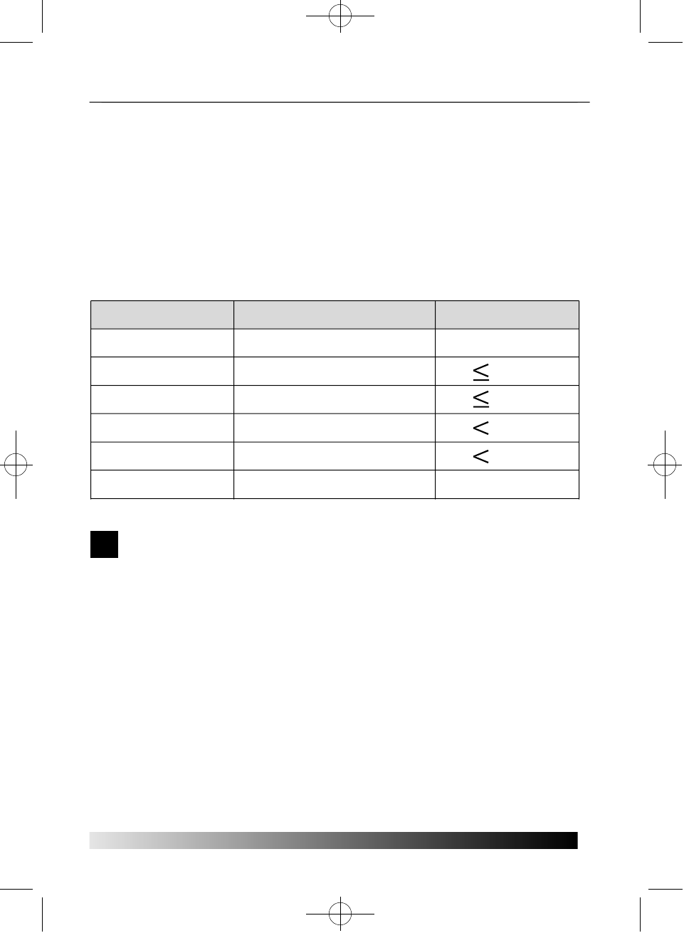
Power consumption
130 W
15 W
15 W
5 W
1 W
0 W
M o d e
N o r m a l
S t a n d b y
S u s p e n d
o f f
Power switch off
U n p l u g g e d
L E D
G r e e n
Green/Orange blinking (1sec.)
Green/Orange blinking (0.5sec.)
O r a n g e
Not illuminated
Not illuminated
!
P910-ENG 01.2.16 10:53 AM ∆‰¿Ã¡ˆ11
User's Guide
1 2
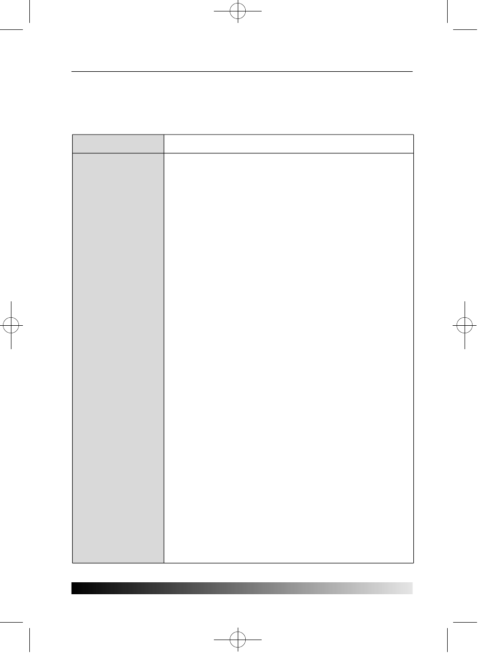
Tro u b l e s h o o t i n g
If your monitor is not functioning properly, you may be able to solve the problem by
reading followings.
P r o b l e m
Blank screen
Error message:
OUT OF RANGE
Self diagnostics
m e s s a g e
NO SIGNAL
The display does
not enter power
management mode
Screen flickers
Color defects
Possible solution
If the power LED is not lit, push the Power switch to turn the
monitor on. If the display unit is powered through the
computer, check that the computer is switched on.
The display unit might be in standby mode. Push one of the
keyboard keys. Check that the keyboard is properly
connected to the computer.
Check that the power cable is correctly connected to the
display unit and to the power outlet.
The graphics adapter is set for too high refresh rate or line
frequency. Select another display mode with lower
frequencies in computer.
This message indicates that the signal is missing or faulty.
Check that the signal cable connector is properly connected
and that the connection pins are not bent or damaged. If the
connector is loose, tighten the connector's screws.
The video signal from the computer does not comply with
VESA DPMS standard. Either the computer or the graphics
adapter is not using the VESA DPMS power management
f u n c t i o n .
The screen may seem to flicker when the refresh rate is less
than 75Hz. See the list of recommended modes in the section
Preset timing table.
If your color is not uniform, demagnetize the display unit as
described in the section Degause under OSD adjustments,
and make sure that the display unit is at least 30cm from any
other electrical equipment.
Check that the signal cable connector is properly connected
and that the connection pins are not bent or damaged. Try
another color temperature.
If the picture has strong color defects, switch off the display
unit and the computer.
P910-ENG 01.2.16 10:53 AM ∆‰¿Ã¡ˆ12
1 3
Contacting service
If the above troubleshooting hints do not help you find a solution to the
problem, contact an authorized service agent. If the monitor is sent for
service, use the original package if possible.
Unplug the display unit from the power outlet and contact a service agent
w h e n :
• The monitor does not operate normally according to the operating instructions.
• The monitor exhibits a distinct change in performance.
• The monitor has been dropped or the cabinet has been damaged.
• The monitor has been exposed to rain, or water or liquid has been spilled onto the
m o n i t o r .
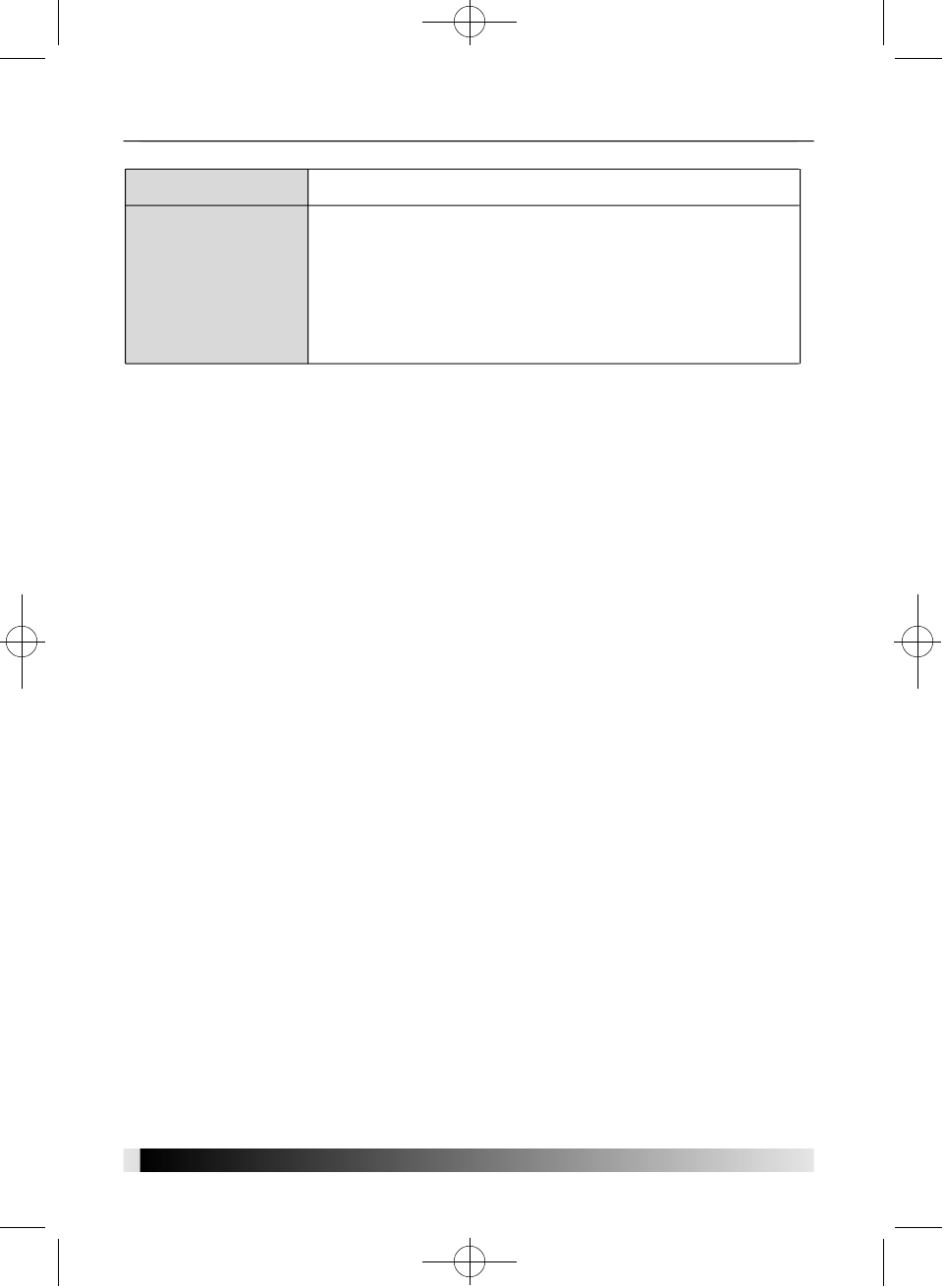
1 3
P r o b l e m
Size, position, shape
or quality
u n s a t i s f a c t o r y
Duplicated images
Possible solution
Make sure that other electrical devices are at least quality
30cm away.
Adjust the picture characteristics as described in the section
Adjusting the picture.
A problem with your graphics adapter or display unit.
Contact your service representative.
P910-ENG 01.2.16 10:53 AM ∆‰¿Ã¡ˆ13
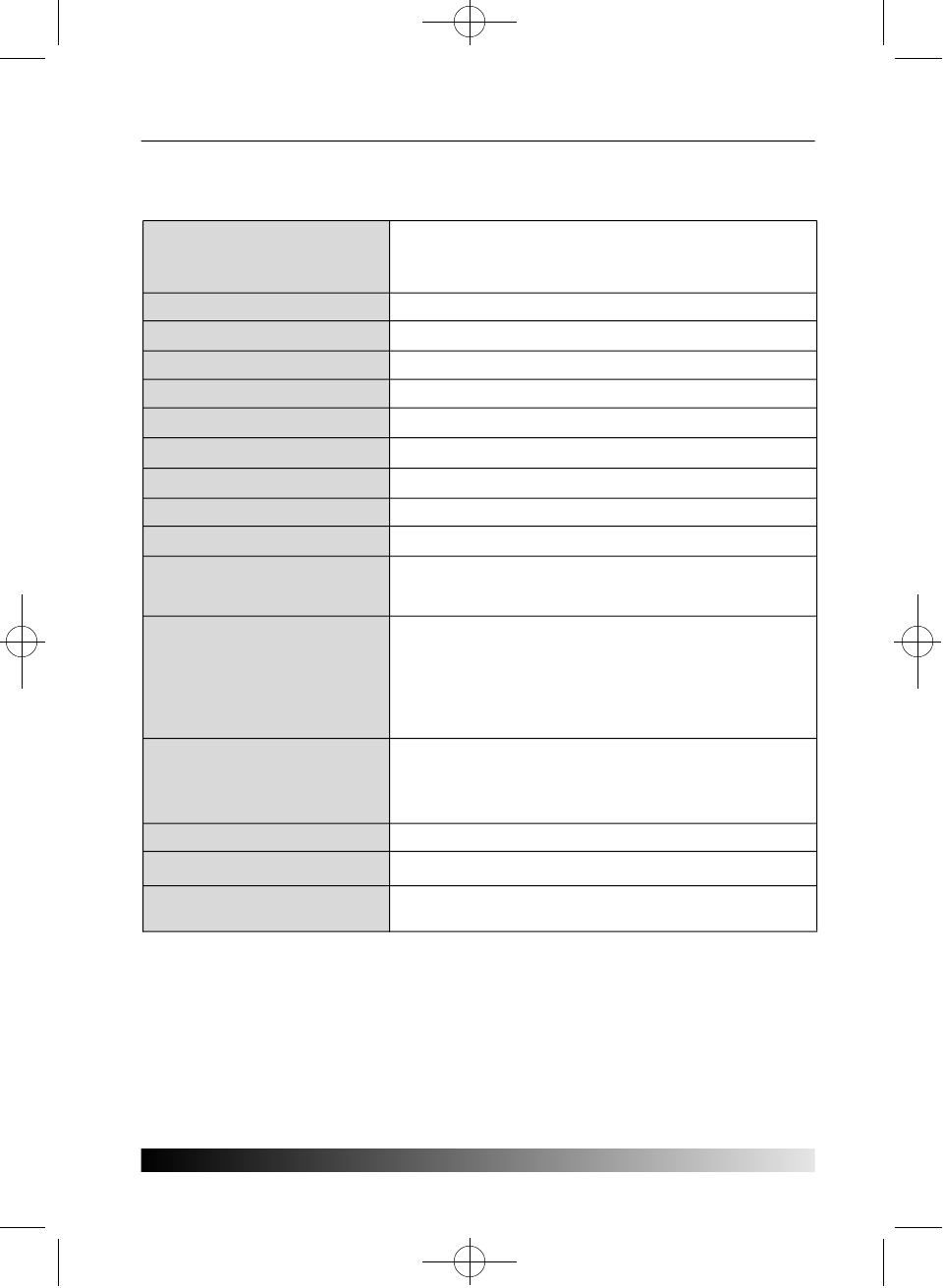
S p e c i f i c a t i o n s
• Specification is subject to change without notice for performance improvement.
User's Guide
1 4
19"(viewable size : 18")
Dot pitch 0.26 mm
Anti-Static, anti-glare, TCO treatment coated.
factory preset area : 352X264 mm
I n f i n i t e
R.G.B Analog, 15 pin D-sub
Horizontal : 30 to 95kHz, Vertical : 50 to 150Hz
202.5 MHz
1 6 0 0 X 1 2 0 0 @ 7 5 H z
100-240 VAC, 2.5A
130W Max
VESA DPMS
Lower than EPA recommendation
VESA DDC 1/2B
H/V SIZE, H/V POSITION, PINCUSHION,
TRAPEZOID, PARALLEL, PIN BALANCE, H/V- MOIRE,
TOP CORNER, BOTTOM CORNER, H/V LINEARITY,
LANGUAGES, ROTATION, OSD H/V POSITION,
COLOR CONTROL, RECALL, INFORMATION, DEGAUSS,
BRIGHTNESS, CONTRAST
T C O
FCC Class B, CE
UL, CSA, TÜV-GS, ISO-9241-3/7/8, DHHS,
NEMKO, DEMKO, FIMKO, SEMKO
0 ~ 40O C
22.5kg unpacked, 26kg packed
4 4 6 X 4 6 5 . 5 X 4 6 8 . 5 m m
Picture tube
Display area
Number of color
Input signals
Frequency rate
Maximum bandwidth
Maximum resolution
Input voltage
Power consumption
Power Management
Plug & Play
OSD menu
E r g o n o m i c s ,
Safety and EMC
Operating Temperature
W e i g h t
Dimensions
(W X H X D mm)
P910-ENG 01.2.16 10:53 AM ∆‰¿Ã¡ˆ14