Hyundai 2006 Tiburon Owners Manual Gkflhma 11.p65
2015-09-08
: Hyundai Hyundai-2006-Tiburon-Owners-Manual-762650 hyundai-2006-tiburon-owners-manual-762650 hyundai pdf
Open the PDF directly: View PDF ![]() .
.
Page Count: 266 [warning: Documents this large are best viewed by clicking the View PDF Link!]

2006

A010A02A-AAT
WARRANTIES FOR YOUR HYUNDAI VEHICLE
Please consult your Owner's Handbook & Warranty Information booklet for your vehicle's specific
warranty coverage.
A020A01A-AAT
RESPONSIBILITY FOR MAINTENANCE
The maintenance requirements for your new Hyundai are found in Section 5. As the owner, it is your responsibility
to see that all maintenance operations specified by the manufacturer are carried out at the appropriate intervals.
When the vehicle is used in severe driving conditions, more frequent maintenance is required for some operations.
Maintenance requirements for severe operating conditions are also included in Section 5.
OWNER'S MANUAL
A030A05F-AAT
Operation
Maintenance
Specifications
All information in this Owner's Manual is current at the time of publication. However, Hyundai reserves the right to make changes at any
time so that our policy of continual product improvement may be carried out.
This manual applies to all Hyundai Tiburon models and includes descriptions and explanations of optional as well as standard equipment.
As a result, you may find material in this manual that does not apply to your specific vehicle.
HGK037

A070A01A-AAT
CAUTION: MODIFICATIONS TO YOUR HYUNDAI
Your Hyundai should not be modified in any way. Such modifications may adversely affect the performance, safety
or durability of your Hyundai and may, in addition, violate conditions of the limited warranties covering the vehicle.
Certain modifications may also be in violation of regulations established by the U.S. Department of Transportation
and other federal or state agencies.
A080A01S-AAT
TWO-WAY RADIO OR CELLULAR TELEPHONE INSTALLATION
Your vehicle is equipped with electronic fuel injection and other electronic components. It is possible for an
improperly installed/adjusted two-way radio or cellular telephone to adversely affect electronic systems. For this
reason, we recommend that you carefully follow the radio manufacturer's instructions or consult your Hyundai
dealer for precautionary measures or special instructions if you choose to install one of these devices.
!
A090A01A-AAT
SAFETY AND VEHICLE DAMAGE WARNING
This manual includes information titled as WARNING, CAUTION and NOTE.
These titles indicate the following:
WARNING:
This indicates that a condition may result in harm, serious injury or death to you or other persons if
the warning is not heeded. Follow the advice provided with the warning.
CAUTION:
This indicates that a condition may result in damage to your vehicle or its equipment if the caution is
not heeded. Follow the advice provided with the caution.
NOTE:
This indicates that interesting or helpful information is being provided.
!
!

A110A01A-AAT
VEHICLE DATA COLLECTION AND EVENT DATA RECORDERS
Your Hyundai vehicle is equipped with many high technology, electronically controlled systems that help to ensure
your vehicle operates properly and provides the performance that you expect. These systems utilize computers
to monitor the operation of various systems and components and help to control their operation. These
computerized system operations are wide-ranging and involve components to reduce emissions, to continuously
evaluate the readiness of the airbag and seat belt pretensioner systems, to determine when the airbag and seat
belt pre-tensioner systems should be deployed and then to activate the deployment, and if equipped, to operate
anti-lock braking, traction control and electrical stability control to assist the driver to control the vehicle in difficult
driving situations. These systems electronically store information that is useful to service technicians when they
need to diagnose and repair these systems. Additional information is stored only when a crash occurs that results
in the deployment of the airbags or seat belt pre-tensioners. This type of data storage is done by devices called
event data recorders(EDR).
After a crash event, the airbag and seat belt pre-tensioner computer system, known as the Supplemental
Restraint System Control Module (SRSCM) or Airbag Control Unit (ACU), may record some information about
the condition of the vehicle and how it was being operated. This information consists of data related to seat belt
usage and if there was diagnostic information in the airbag or seat belt systems at the time that a crash occurred,
and if the ACU sensed that a crash of sufficient severity occurred to require seat belt pre-tensioner or airbag
deployment.
To retrieve this information, special equipment is needed and access to the vehicle or the device that stores the
data is required. Hyundai will not access information about a crash event or share it with others except:
o in response to an official request of police or similar government office, or
o with the consent of the vehicle owner or, if the vehicle is leased, with the consent of the lessee, or
o as part of Hyundai’s defense of litigation, or
o as required by law.

A040A01A-AAT
FOREWORD
Thank you for choosing Hyundai. We are pleased to welcome you to the growing number of discriminating people who
drive Hyundais. The advanced engineering and high-quality construction of each Hyundai we build is something of which
we're very proud.
Your Owner's Manual will introduce you to the features and operation of your new Hyundai. It is suggested that you read
it carefully because the information it contains can contribute greatly to the satisfaction you receive from your new car.
The manufacturer also recommends that all service and maintenance on your car be performed by an authorized Hyundai
dealer. Hyundai dealers are prepared to provide high-quality service, maintenance and any other assistance that may
be required.
A050A04A-AAT
HYUNDAI MOTOR COMPANY
Note : Because future owners will also need the information included in this manual, if you sell this Hyundai, please leave
the manual in the vehicle for their use. Thank you.
CAUTION:
Severe engine and transaxle damage may result from the use of poor quality fuels and lubricants that do not
meet Hyundai specifications. You must always use high quality fuels and lubricants that meet the specifica-
tions listed on Page 9-4 in the Vehicle Specifications section of the Owner's Manual and which also appear
in the Service Station Information on the back cover of the Owner's Manual.
Copyright 2006 Hyundai Motor Company. All rights reserved. No part of this publication may be reproduced, stored in
any retrieval system or transmitted in any form or by any means without the prior written permission of Hyundai Motor
Company.
!
A100A03A-AAT
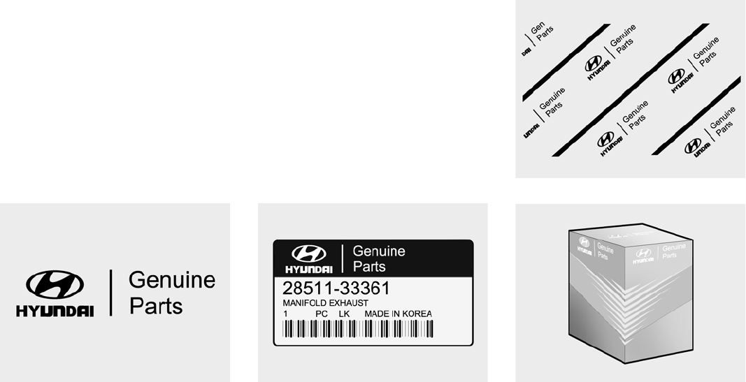
GUIDE TO HYUNDAI GENUINE PARTS
1. What are Hyundai Genuine Parts?
Hyundai Genuine Parts are the same parts
used by Hyundai Motor Company to manu-
facture vehicles. They are designed and
tested for the optimum safety, performance,
and reliability to our customers.
2. Why should you use genuine parts?
Hyundai Genuine Parts are engineered and
built to meet rigid manufacturing require-
ments. Using imitation, counterfeit or used
salvage parts is not covered under the
Hyundai New Vehicle Limited Warranty or
any other Hyundai warranty. In addition, any
damage to or failure of Genuine Hyundai
Parts caused by the installation or failure of
an imitation, counterfeit or used salvage part
is not covered by any Hyundai Warranty.
3. How can you tell if you are purchasing
Hyundai Genuine Parts?
Look for the Hyundai Genuine Parts Logo on
the package (see below).
Hyundai Genuine Parts exported to the United
States are packaged with labels written only
in English.
Hyundai Genuine Parts are only sold through
authorized Hyundai Dealerships.
To find the closest authorized dealer call
1-800-826-CARS
A100A01L A100A02L A100A04L
A100A03L

TABLE OF CONTENTS
SECTION
5
1
2
3
4
6
7
8
9
10
FEATURES OF YOUR HYUNDAI
DRIVING YOUR HYUNDAI
WHAT TO DO IN AN EMERGENCY
CORROSION PREVENTION & APPEARANCE CARE
VEHICLE MAINTENANCE REQUIREMENTS
DO-IT-YOURSELF MAINTENANCE
EMISSION CONTROL SYSTEMS
CONSUMER INFORMATION, REPORTING SAFETY DEFECTS &
BINDING ARBITRATION OF WARRANTY CLAIMS
VEHICLE SPECIFICATIONS
INDEX
INSTRUMENTS AND CONTROLS
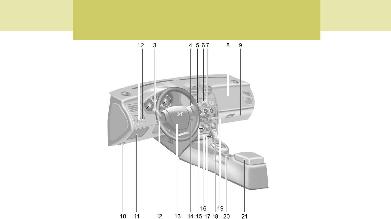
B250A02GK-AAT
B250A01GK-A
1. Electronic Stability Program (ESP) Switch (If installed)
2. Panel Brightness Control Knob
(Rheostat Switch)
3. Multi-Function Light Switch
4. Windshield Wiper/Washer Switch
5. Front Fog Light switch (If installed)
6. Hazard Warning Switch
7. Digital Clock
8. Passenger's Air Bag
9. Glove Box
10.Hood Release Lever
11.Fuse Box Relay
12.Steering Wheel Tilt Lever (If installed)
13.Horn and Driver's Airbag
14.Cruise Control Switch (If installed)
15.Heating and Cooling Controls
16.Ashtray
17.Cigarette Lighter
18.Shift Lever
19.Audio System (If installed)
20.Parking Brake Lever
21.Center Console
CAUTION:
When installing a container of liquid air freshener inside the vehicle, do not place it near the instrument cluster nor
on the instrument panel surface. If there is any leakage from the air freshener onto these areas (Instrument cluster,
instrument panel or air ventilator), it may damage these parts. If the liquid from the air freshener does leak onto
these areas, wash them with water immediately.
!
YOUR VEHICLE AT A GLANCE
B255A02GK-AAT
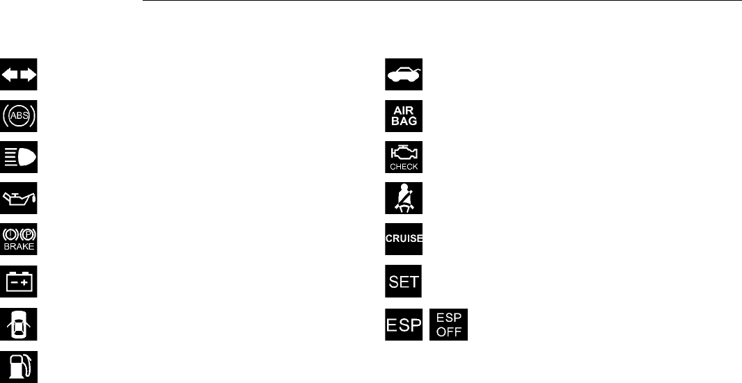
INDICATOR SYMBOLS ON THE INSTRUMENT PANEL
* More detailed explanations of these items will be found beginning on page 1-38.
Malfunction Indicator Light
SRS (Airbag) Service Reminder Indicator (SRI)
Tail Gate Open Warning Light
Low Fuel Level Warning Light
Door Ajar Warning Light and Chime
ABS Service Reminder Indicator (SRI) (If installed)
Turn Signal Indicator Lights
High Beam Indicator Light
Low Oil Pressure Warning Light
Parking Brake/ Low Brake Fluid Level Warning Light
Charging System Warning Light
CRUISE Indicator Light (If installed)
Seat Belt Reminder Light and Chime
CRUISE SET Indicator Light (If installed)
Electronic Stability Program (ESP)
Indicator Lights (If installed)

FEATURES OF YOUR HYUNDAI
1
Fuel Recommendations ................................................ 1-2
Breaking in Your New Hyundai ..................................... 1-3
Keys.............................................................................. 1-3
Door (Teft-Alarm System) ...................................... 1-4, 1-6
Power Windows ............................................................ 1-9
Seats ........................................................................... 1-10
Seat Belts.................................................................... 1-16
Child Restraint System ............................................... 1-21
Supplemental Restraint (AIRBAG) System (SRS) ..... 1-28
Instrument Cluster and Indicator Lights ...................... 1-36
Warning and Indicator Lights ...................................... 1-38
Multi-Function Light Switch ......................................... 1-47
Windshield Wiper/Washer Switch ............................... 1-49
Sunroof ....................................................................... 1-55
Mirror ........................................................................... 1-58
Hood Release ............................................................. 1-61
Cruise Control ............................................................. 1-67
Audio Remote Control Switch ..................................... 1-70
Heating and Cooling Control ....................................... 1-71
Stereo Sound System ................................................. 1-88
Audio System.............................................................. 1-90
Antenna ..................................................................... 1-127
1
1FEATURES OF YOUR HYUNDAI
2FUEL RECOMMENDATIONS
CAUTION:
Your Hyundai's New Vehicle Limited War-
ranty may not cover damage to the fuel
system and any performance problems that
are caused by the use of fuels containing
methanol or fuels containing MTBE (Methyl
Tertiary Butyl Ether) over 15.0% vol. (Oxy-
gen Content 2.7% weight.)
B010B01A-AAT
What About Gasohol?
Gasohol (a mixture of 90% unleaded gasoline
and 10% ethanol or grain alcohol) may be used
in your Hyundai. However, if your engine devel-
ops driveability problems, the use of 100%
unleaded gasoline is recommended. Fuels with
unspecified quantities of alcohol, or alcohols
other than ethanol, should not be used.
B010A02JM-AAT
Use Unleaded Gasoline
Unleaded gasoline with a Pump Octane
Rating of 87 (Research Octane Number 91)
or higher must be used in your Hyundai.
B010D01A-AAT
Do Not Use Methanol
Fuels containing methanol (wood alcohol) should
not be used in your Hyundai. This type of fuel
can reduce vehicle performance and damage
components of the fuel system.
!
B010A02GK
UNLEADED
FUEL ONLY
B010C01A-AAT
Use of MTBE
Hyundai recommends that fuels containing
MTBE (Methyl Tertiary Butyl Ether) over 15.0%
vol. (Oxygen Content 2.7% weight) should not
be used in your Hyundai.
Fuel containing MTBE over 15.0% vol. (Oxygen
Content 2.7% weight) may reduce vehicle per-
formance and produce vapor lock or hard
starting.
!WARNING:
o Do not "top off" after the nozzle auto-
matically shuts off when refueling.
o Tighten the cap until it clicks, otherwise
the " " light will illuminate.
o Always check that the fuel cap is in-
stalled securely to prevent fuel spillage
in the event of an accident.

1
FEATURES OF YOUR HYUNDAI
3
BREAKING IN YOUR NEW
HYUNDAI
B010E01A-AAT
Gasolines for Cleaner Air
To help contribute to cleaner air, Hyundai rec-
ommends that you use gasolines treated with
detergent additives, which help prevent deposit
formation in the engine. These gasolines will
help the engine run cleaner and enhance per-
formance of the Emission Control System.
B010F01A-AAT
Operation in Foreign Countries
If you are going to drive your Hyundai in another
country, be sure to:
o Observe all regulations regarding registra-
tion and insurance.
o Determine that acceptable fuel is available.
B020A01S-AAT
During the First 1,200 Miles (2,000 Km)
No formal "break-in" procedure is required with
your new Hyundai. However, you can contrib-
ute to the economical operation and durability of
your Hyundai by observing the following recom-
mendations during the first 1,200 miles (2,000
km).
o Don't drive faster than 55 MPH (88 km/h).
o While driving, keep your engine speed (rpm,
or revolutions per minute) between 2,000
rpm and 4,000 rpm.
o Use moderate acceleration. Don't start
quickly or depress the accelerator pedal
fully.
o For the first 200 miles (300 km), try to avoid
hard stops.
o Don't lug the engine (in other words, don't
drive so slowly in too high a gear that the
engine "bucks"-shift to a lower gear).
o Whether going fast or slow, vary your speed
from time to time.
o Don't let the engine idle longer than 3 minutes
at one time.
o Don't tow a trailer during the first 1,200 miles
(2,000 km) of operation.
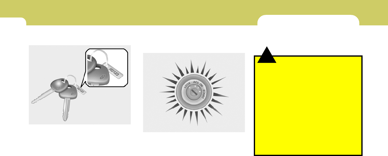
KEYS
B030A01A-AAT
For greater convenience, the same key oper-
ates all the locks in your Hyundai. However,
because the doors can be locked without a key,
carrying a spare key is recommended in case
you accidentally lock one key inside the car.
B030A01E
1FEATURES OF YOUR HYUNDAI
4
WARNING:
o Unlocked doors can be dangerous. Be-
fore you drive away (especially if there
are children in the car), be sure that all the
doors are securely closed and locked so
that the doors cannot be inadvertently
opened from the inside. This helps en-
sure that the doors will not be opened
accidentally. Also, when combined with
the proper use of seat belts, locking the
doors helps keep occupants from being
ejected from the car in case of an acci-
dent.
o Before opening the door, always look for
and avoid oncoming traffic.
o In case of accident, the door is unlocked
automatically (If installed).
!
DOOR
B040A02Y-AAT
DOOR LOCKS
B030C01Y-AAT
ILLUMINATED IGNITION SWITCH
(If installed)
Whenever a door is opened, the ignition switch
will be illuminated for your convenience, pro-
vided the ignition switch is not in the "ON"
position.
The light will go off approximately 10 seconds
after closing the door or when the ignition switch
is turned on.
B030C01E-1
B030B01S-AAT
Record Your Key Number
A code number is stamped on the key number
plate that came with the keys to your Hyundai.
This key number plate should be kept in a safe
place, not in the vehicle. The key number should
also be recorded in a place where it can be found
in an emergency.
If you need additional keys, or if you should lose
your keys, your authorized Hyundai dealer can
make new keys if you can supply the key
number.
B030B01E
1
FEATURES OF YOUR HYUNDAI
5
B040C01S-AAT
Locking From the Outside
The doors can be locked without a key.
To lock the doors first push the inside lock
switch to the "LOCK" position so that the red
mark on the switch is not visible, then close the
door.
NOTE:
o When locking the door this way, be care-
ful not to lock the door with the ignition
key left in the vehicle.
o To reduce the chance of theft, always
remove the ignition key, close all win-
dows, and lock all doors when leaving
your vehicle unattended.
HGK2009
B040B01JM-AAT
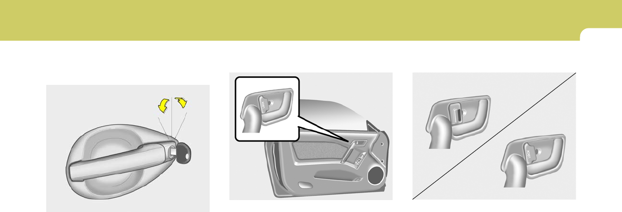
Locking and unlocking front doors with a
key
o The door can be locked or unlocked with a
key.
o Lock the door by turning the key toward the
front of the vehicle and unlock it by turning the
key toward the rear.
NOTE:
The driver's door can be unlocked by turn-
ing the key once toward the rear. If you wish
to unlock all doors, turn the key again
toward the rear within 4 seconds.
The passenger's side will lock or unlock all
doors with just one rotation.
HGK2008
LOCK
UNLOCK
B040D01S-AAT
Locking From the Inside
To lock the doors from the inside, simply close
the door and push the lock switch to the "LOCK"
position. When this is done, neither the outside
nor the inside door handle can be used.
NOTE:
When the door is locked, the red mark on the
switch is not visible.
HGK2010
UNLOCK
LOCK
1FEATURES OF YOUR HYUNDAI
6
B070B02GK-AAT
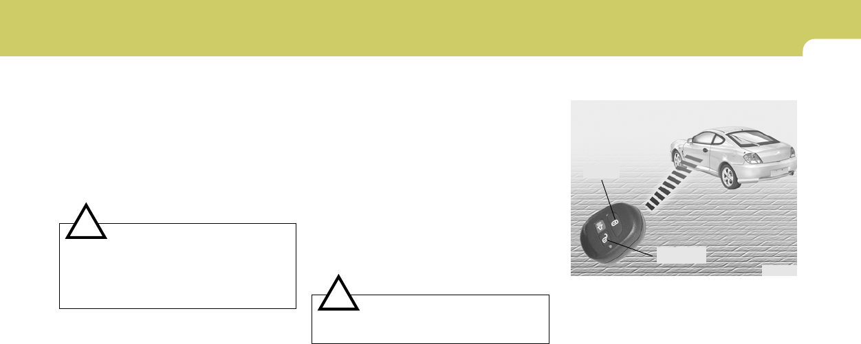
Armed Stage
Park the car and stop the engine. Arm the
system as described below.
1) Remove the ignition key from the ignition
switch.
2) Make sure that the engine hood and tail gate
are closed and latched.
3) Lock the doors using the transmitter of the
keyless entry system.
After completion of the steps above, the turn
signal light will blink once to indicate that the
system is armed.
HGK2009
B040G02GK-GAT
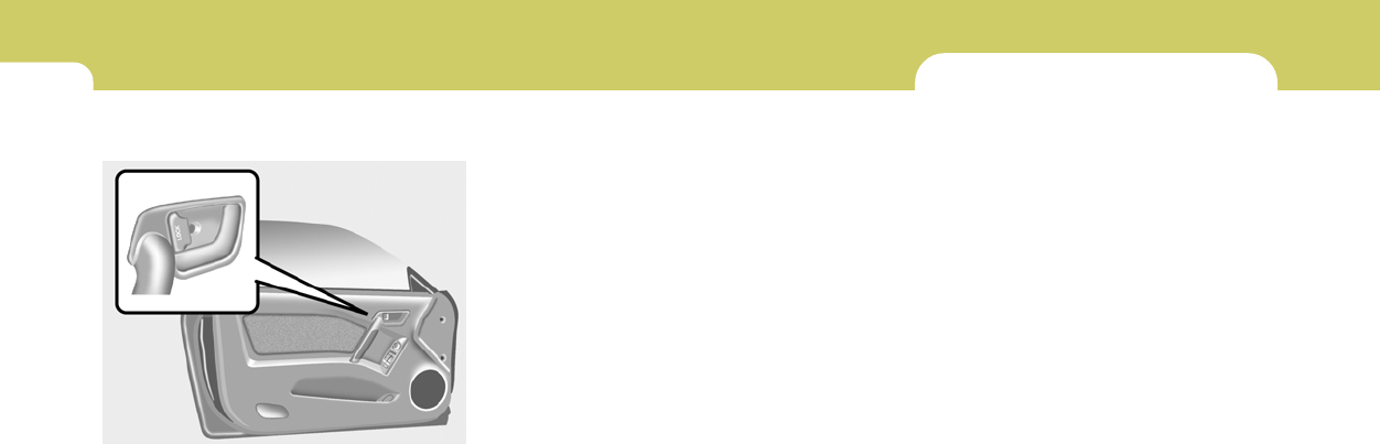
Central Door Lock
The central door locking is operated by pushing
the driver's door lock switch toward the front or
rear of the vehicle. If the passenger door is open
when the switch is pushed, the door will remain
locked when closed.
NOTE:
o When pushing the switch toward the
rear, all doors will unlock.
When pushing the switch toward the
front, all doors will lock.
o When the door is unlocked, the red mark
on the switch is visible.
o The central door locking is operated by
turning the key (driver's door only) to-
ward the front or rear of the vehicle.
THEFT-ALARM SYSTEM
B070A01A-AAT
(If Installed)
This system is designed to provide protection
from unauthorized entry into the car. This sys-
tem is operated in three stages: the first is the
"Armed" stage, the second is the "Alarm" stage,
and the third is the "Disarmed" stage. If trig-
gered, the system provides an audible alarm
with blinking of the turn signal light.
o If the door is locked/unlocked multiple
times in rapid succession with either the
vehicle key or door lock switch, the sys-
tem may stop operating temporarily in
order to protect the circuit and prevent
damage to system components.
1
FEATURES OF YOUR HYUNDAI
7
!
NOTE:
1) If any door, tail gate or engine hood
remains open, the system will not be
armed.
2) If this happens, rearm the system as
described above.
3) Once the system is armed, only the tail
gate may be unlocked using the key
without disarming the system.
CAUTION:
Do not arm the system until all passengers
have left the car. If the system is armed while
a passenger(s) remains in the car, the alarm
may be activated when the remaining
passenger(s) leaves the car.
B070C01GK-AAT
Alarm Stage
The alarm will be activated if any of the following
occur while the car is parked and the system is
armed.
1) A front door is unlocked and opened without
using the transmitter.
2) The tail gate is opened without using the key.
3) The engine hood is opened.
The siren will sound and the turn signal lamp will
blink continuously for 30 seconds. (This hap-
pens 3 times). To turn off the system, unlock the
door with the transmitter.
CAUTION:
Avoid trying to start the engine while the
system is armed.
!
B070D04GK-AAT
Disarmed Stage
The system will be disarmed when either of the
following steps are taken:
1) The driver's or passenger's door is un-
locked by depressing the "UNLOCK" button
on the transmitter.
2) In the middle of alarming or after alarming, it
keeps for 30 seconds when the key is turned
to the "ON" position.
After completing one of steps above, the turn
signal light will blink twice to indicate that the
system is disarmed.
NOTE:
If any door, tail gate or engine hood is not
opened within 30 seconds, the system will
be rearmed.
HGK102
LOCK
UNLOCK
1FEATURES OF YOUR HYUNDAI
8
!
B070F02A-AAT
KEYLESS ENTRY SYSTEM (If installed)
NOTE:
This device complies with Part 15 of the
FCC rules. Operation is subject to the fol-
lowing two conditions:
(1) This device may not cause harmful in-
terference, and (2) this device must accept
any interference received, including inter-
ference that may cause undesired opera-
tion.
WARNING:
Changes or modifications not expressly
approved by the party responsible for com-
pliance could void the user's authority to
operate the equipment.
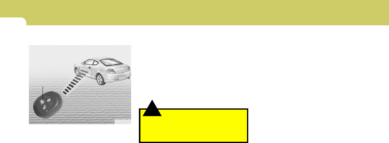
Locking doors
1. Close all doors.
2. Push the "LOCK" button on the transmitter.
3. At the same time all doors lock, the turn signal
lights will blink once to indicate that the
system is armed.
Unlocking doors
1. Push the "UNLOCK" button on the transmitter.
2. At the same time all doors unlock, the turn
signal lights will blink twice to indicate that the
system is disarmed.
NOTE:
The transmitter will not work if any of fol-
lowing occur:
- The ignition key is in ignition switch.
- You exceed the operating distance limit
(10 m).
- The battery in the transmitter is weak.
- Other vehicles or objects may be block-
ing the signal.
- The weather is extremely cold.
- The transmitter is close to a radio trans-
mitter such as a radio station or an
airport which can interfere with normal
operation of the transmitter.
When the transmitter does not work cor-
rectly, open and close the door with the
ignition key. If you have a problem with the
transmitter, contact an authorized Hyundai
Dealer.
NOTE:
Keep the transmitter away from water or
any liquid. If the keyless entry system is
inoperative due to exposure to water or
liquids, it will not be covered by your manu-
facturer vehicle warranty.
B075E01O-AAT
Panic Warning
1. Push the "PANIC" button on the transmitter.
2. At the same time, the siren will sound and the
turn signal lights will blink for 30 seconds.
3. To turn off the system, push the "PANIC"
button again on the transmitter.
HGK102
PANIC
1
FEATURES OF YOUR HYUNDAI
9
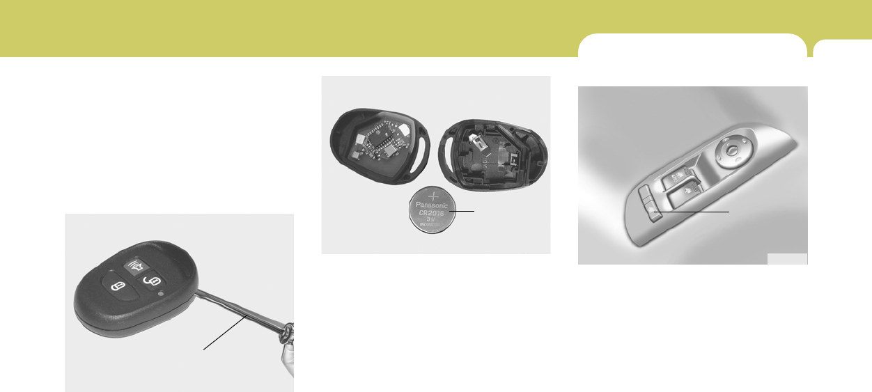
B070E02GK-GAT
Replacing the battery
When the transmitter's battery begins to get
weak, it may take several pushes on the button
to lock or unlock the doors, and the LED will not
light. Replace the battery as soon as possible.
Battery type : CR2016
Replacement instructions:
1. Carefully separate the case with a blade
screwdriver as shown in the illustration.
HGK122
Screwdriver
2. Remove the old battery from the case and
note the polarity. Make sure the polarity of
the new battery is the same(+side facing up),
then insert it in the transmitter.
NOTE:
Install a new battery within 30 seconds after
removing the old one. If installing a new
battery takes more than 30 seconds, take
the following steps.
1) Turn the ignition key to the "ACC" posi-
tion.
2) Make sure that the turn signal lamps
blink once by pushing the "LOCK" or
"UNLOCK" button on the transmitter.
HGK121
Battery
POWER WINDOW
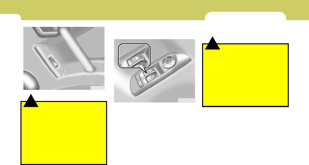
B050A01GK-AAT
The power windows operate only when the
ignition key is in the "ON" position. The main
switches are located on the driver's arm rest
and control the front windows on the respective
sides of the vehicle. The windows may be
opened by depressing the front portion of the
switch. To stop at the desired opening, release
the switch. The window may be closed by pulling
the front portion of the switch. In order to prevent
operation of the passenger front window by the
passenger, a window lock switch (1) is provided
on the arm rest of the driver's door. To disable
the passenger's power window, push the win-
dow lock switch. To revert to normal operation,
push in on the window lock switch again.
HGK2015
(1)
1FEATURES OF YOUR HYUNDAI
10
Auto-Down Window (Driver's Side)
(If Installed)
The Auto-Down window is moved to its fully
open position by pushing the switch. To stop at
the desired position push in on the switch again.
B050A02GK
!
HGK2016
WARNING:
(1) Be careful that someone's head, hands
and body are not trapped by a closing
window.
(2) Never try to operate the main switch on
the driver's door and the individual door
window switch in opposing directions
at the same time. If this is done, the
window will stop and cannot be opened
or closed.
(3) Do not leave children alone in the car.
Always remove the ignition key for their
safety.
SEATS
B080A02A-AAT
ADJUSTABLE FRONT SEATS
!WARNING:
o Never adjust the driver’s seat while the
vehicle is moving. Any sudden or unex-
pected movement of the seat could cause
you to lose control of the vehicle result-
ing in an accident. Only adjust the
driver’s seat when the vehicle is station-
ary.
o Do not sit or lean unnecessarily close to
the airbag. Position the seat so that you
can sit as far back as possible from the
airbag and still comfortably reach all
controls.
1
FEATURES OF YOUR HYUNDAI
11
!
B080B03A-AAT
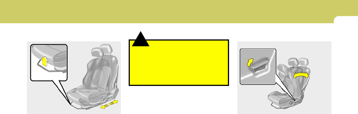
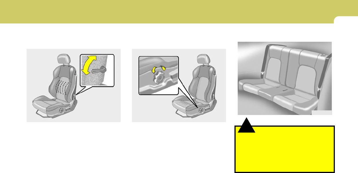
Adjusting Seat Forward and Rearward
To move the seat toward the front or rear, pull
the lock release lever upward. This will release
the seat on its track so you can move it forward
or rearward to the desired position. When you
find the position you want, release the lever and
slide the seat forward or rearward on its track
until it locks into the desired position and cannot
be moved further.
HGK2027
WARNING:
After adjusting the seat, always check that
it is securely locked into place by attempt-
ing to move the seat forward or reverse
without using the lock release lever. Sud-
den or unexpected movement of the driver's
seat could cause you to lose control of the
vehicle resulting in an accident.
B080C02A-AAT
Adjusting Seatback Angle
To recline the seatback, lean forward to take
your weight off it, then pull up on the recliner
control lever at the outside edge of the seat. Now
lean back until the desired seatback angle is
achieved. To lock the seatback into position,
release the recliner control lever.
HGK2028
1FEATURES OF YOUR HYUNDAI
12
!
B080D01JM
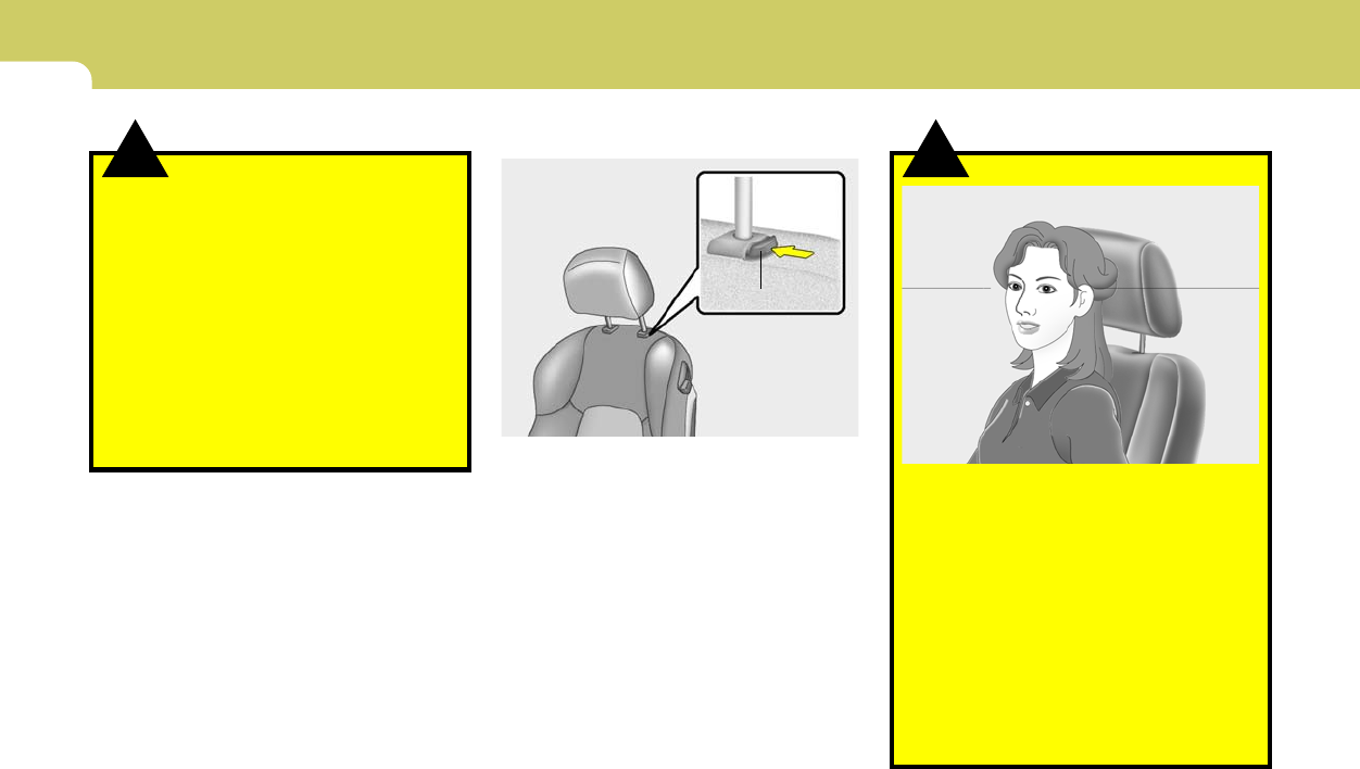
o For maximum effectiveness in case of an
accident the headrest should be ad-
justed so the middle of the headrest is at
the same height as the top of the
occupant's eyes. For this reason, the
use of a cushion that holds the body
away from the seatback is not recom-
mended.
o Do not operate vehicle with the head-
rests removed as injury to the occupants
may occur in the event of an accident.
Headrests may provide protection against
neck injuries when properly adjusted.
o Do not adjust the headrest hejght while
the vehicle is in motion.
WARNING:
!WARNING:
Riding with a reclined seatback increases
your chance of serious or fatal injuries in
the event of a collision or sudden stop. The
protection of your restraint system (seat
belts and airbags) is greatly reduced by
reclining your seat. Seat belts must be snug
against your hips and chest to work prop-
erly. The more the seatback is reclined, the
greater the chance that an occupant's hips
will slide under the lap belt or the occupant's
neck will strike the shoulder belt. Drivers
and passengers should always sit well back
in their seats, properly belted, and with the
seatbacks upright.
B080D02JM-AAT
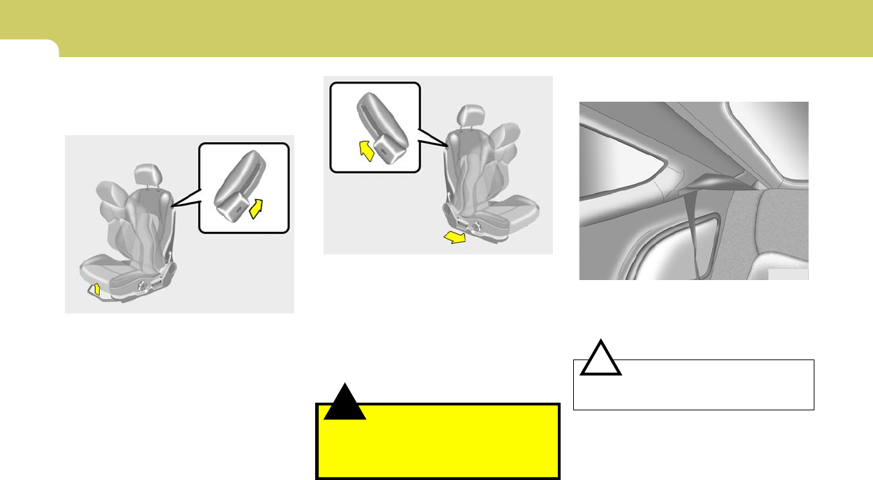
Adjustable Headrests
Headrests are designed to help reduce the risk
of neck injuries.
To raise the headrest, pull it up. To lower the
headrest, push it down while pressing the lock
knob. To remove the headrest, raise it as far as
it can go then press the lock knob while pulling
upward. This should only be done when the seat
is not occupied.
Lock Knob
HGK2032
1
FEATURES OF YOUR HYUNDAI
13
B080F01F-AAT
Seat Cushion Height Adjustment
(Driver's Seat Only) (If Installed)
To raise or lower the front part of the seat
cushion, turn the knob forward or rearward.
HGK2029
B080E01F-AAT
Lumbar Support Control
(Driver's seat only)
The driver's seat is equipped with adjustable
lumbar support.
To increase the amount of lumbar support, pull
the lever forward.
To decrease it, push the lever toward the rear.
SOFT
HGK2030
FIRM
!
B129A01F-AAT
REAR SEAT POSITIONS
WARNING:
This vehicle contains two rear seating po-
sitions only and a seat belt for each seating
position. Thus, never permit more than two
occupants to ride in the rear seat because
an unrestrained occupant could be seri-
ously injured or killed in the event of a
vehicle crash.
B129A01GK
1FEATURES OF YOUR HYUNDAI
14
B099A01F-AAT
BEFORE FOLDING THE REAR SEATS
In order to prevent the shoulder belt from being
damaged while folding the rear seat, the shoul-
der belt must be passed through the hanger to
keep it out of the way.
CAUTION:
Seat belts must be removed from the hanger
when in use.
!
HGK2034
B130A01GK-AAT
REAR SEAT ENTRY (Walk in device)
The driver and front passenger's seatbacks
should be tilted to enter the rear seat.
By pulling up the walk in device lever (1) at the
left-upper side of the driver side seatback, the
seatback will tilt forward. Then pull the lock
release lever (2) up to move the seat forward.
HGK2036
(1)
(2)
!
By pulling up the walk in device lever (1) at the
right-upper side of the passenger side seatback,
the seatback will tilt forward. Then push the seat
forward to allow the occupants to enter.
Recliner Memory
By pulling up the walk in device lever (1) the
seatback is reclined and returned to the original
position.
WARNING:
Don't drive with the passenger side seatback
reclined. It is dangerous to move it while
driving. Be sure the seatback is caterred
firmly before driving.
HGK2036-1
(1)
1
FEATURES OF YOUR HYUNDAI
15
!WARNING:
The purpose of the fold-down rear
seatbacks is to allow you to carry longer
objects than could otherwise be accommo-
dated. Never allow passengers to sit on top
of the folded down seat back while the car
is moving as this is not a proper seating
position and no seat belts are available for
use. This could result in injury in case of an
accident or sudden stop. Objects carried
on the folded down seatback should not
extend higher than the top of the front
seats. This could allow cargo to slide for-
ward and cause injury or damage during
sudden stops.
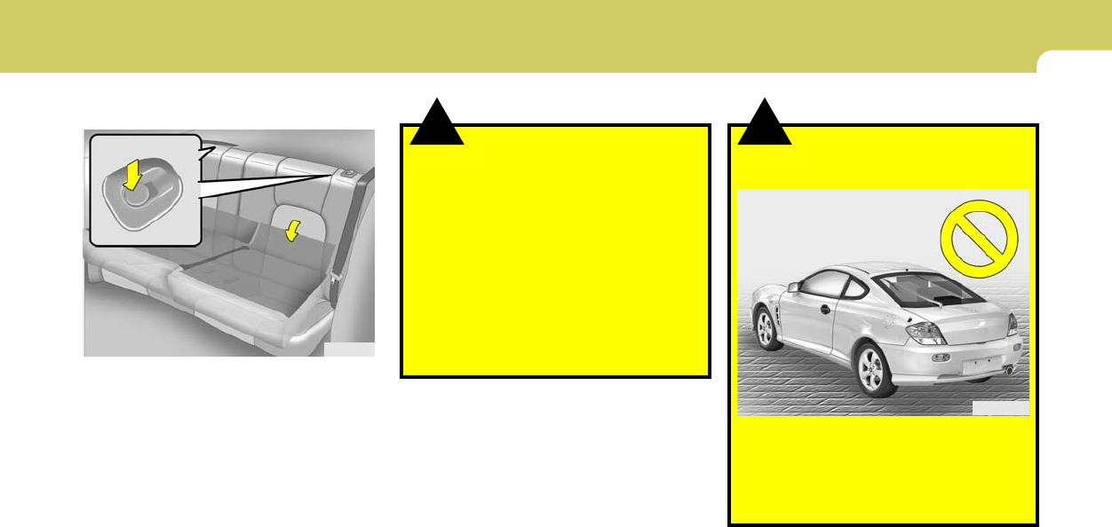
B110A02S-AAT
FOLDING REAR SEATBACKS
The rear seatbacks may be folded to facilitate
carrying long items or to increase the luggage
capacity of the vehicle.
o To unlock the seatback, push the seatback
locking button, then pull forward on the
seatback panel.
o When you return the seatback to its upright
position, always be sure it has locked into
position by pulling and pushing on the top of
the seatback.
HGK2035
!
B140A01S-AAT
REAR SEAT WARNING
For the safety of all passengers, luggage or
other cargo should not be piled higher than the
top of the seatback. In addition, do not place
objects on the rear shelf as they may move
forward during braking or in an accident and
strike vehicle passengers.
B140A01GK

1FEATURES OF YOUR HYUNDAI
16
B150C02A-AAT
Larger Children
Children who are too large for child restraint
systems should always occupy the rear seat
and use the available lap/shoulder belts. The lap
portion should be fastened snug on the hips and
as low as possible. Check belt fit periodically. A
child's squirming could put the belt out of posi-
tion. Children are afforded the most safety in the
event of an accident when they are restrained
by a proper restraint system in the rear seat. If
a larger child (over age 13) must be seated in
the front seat, the child should be securely
restrained by the available lap/shoulder belt and
the seat should be placed in the rearmost
position. Children under the age of 13 should be
restrained securely in the rear seat. Never
place a child under the age of 13 in the front seat.
NEVER place a rear facing child seat in the front
seat of a vehicle.
for your child's height and weight. Check
the label on the child restraint for this
information. See page 1-21.
!
B150B04Y-AAT
Infant or Small Child
All 50 states have child restraint laws. You
should be aware of the specific requirements in
your state. Child and/or infant safety seats must
be properly placed and installed in the rear seat.
Information about the use of these restraints
begins on page 1-21.
WARNING:
Every person in your vehicle needs to be
properly restrained at all times, including
infants and children. Never hold a child in
your arms or lap when riding in a vehicle.
The violent forces created during a crash
will tear the child from your arms and throw
the child against the interior. Always use a
child restraint appropriate for your child's
height and weight, see page 1-21.
NOTE:
Small children are best protected from in-
jury in an accident when properly restrained
in the rear seat by a child restraint system
that meets the requirements of the Federal
Motor Vehicle Safety Standards. Before
buying any child restraint system, make
sure that it has a label certifying that it
meets Federal Motor Vehicle Safety Stan-
dard 213. The restraint must be appropriate
!
SEAT BELT
B150A02S-AAT
SEAT BELT PRECAUTIONS
WARNING:
All occupants of the vehicle must wear their
seat belts at all times. Seat belts and child
restraints reduce the risk of serious or fatal
injuries for all occupants in the event of a
collision or sudden stop. Without a seat
belt, occupants could be shifted too close
to a deploying airbag, strike the interior
structure or be thrown from the vehicle.
Properly worn seat belts greatly reduce
these hazards. Even with advanced airbags,
unbelted occupants can be severely in-
jured by a deploying airbag. Always follow
the precautions about seat belts, airbags
and occupant safety contained in this
manual.

1
FEATURES OF YOUR HYUNDAI
17
!
B150G02A-AAT
Do Not Lie Down
To reduce the chance of injuries in the event of
an accident and to achieve maximum effective-
ness of the restraint system, all passengers
should be sitting up and the front seats should
be in an upright position when the car is moving.
A seat belt cannot provide proper protec-tion if
the person is lying down in the rear seat or if the
front seat is in a reclined position.
WARNING:
Riding with a reclined seatback increases
your chance of serious or fatal injuries in
the event of a collision or sudden stop. The
protection of your restraint system (seat
belts and airbags) is greatly reduced by
reclining your seat. Seat belts must be snug
against your hips and chest to work prop-
erly. The more the seatback is reclined, the
greater the chance that an occupant's hips
will slide under the lap belt causing serious
internal injuries or the occupant's neck
could strike the shoulder belt. Drivers and
passengers should always sit well back in
their seats, properly belted (see page 1-19),
and with the seatbacks upright.
B150D01A-AAT
Pregnant Women
The use of a seat belt is recommended for
pregnant women to lessen the chance of injury
in an accident. When a seat belt is used, the lap
belt portion should be placed as low and snugly
as possible on the hips, not across the abdo-
men. For specific recommendations, consult a
physician.
B150E01A-AAT
Injured Person
A seat belt should be used when an injured
person is being transported. When this is nec-
essary, you should consult a physician for
recommendations.
B150F01A-AAT
One Person Per Belt
Two people (including children) should never
attempt to use a single seat belt. This could
increase the severity of injuries in case of an
accident.
!
B160A02A-AAT
CARE OF SEAT BELTS
Seat belt systems should never be disassembled
or modified. In addition, care should be taken to
assure that seat belts and belt hardware are not
damaged by seat hinges, doors or other abuse.
WARNING:
When you return the rear seatback to its
upright position after the rear seatback was
folded down, be careful not to damage the
seat belt webbing or buckle. Be sure that
the webbing or buckle does not get caught
or pinched in the rear seat. A seat belt with
damaged webbing or buckle will not be as
strong and could possibly fail during a
collision or sudden stop, resulting in seri-
ous injury.
B160B01A-AAT
Periodic Inspection
It is recommended that all seat belts be in-
spected periodically for wear or damage of any
kind. Parts of the system that are damaged
should be replaced as soon as possible.

1FEATURES OF YOUR HYUNDAI
18
!
Release the button to lock the anchor into
position. Try sliding the height adjuster to make
sure that it has locked into the position.
WARNING:
o Verify the shoulder belt anchor is locked
into position at the appropriate height.
Never position the shoulder belt across
your neck or face. Improperly posi-
tioned seat belts can cause serious inju-
ries in an accident.
o Failure to replace seat belts after an
accident could leave you with damaged
seat belts that will not provide protec-
tion in the event of another collision
leading to personal injury or death.
Replace your seat belts after being in an
accident as soon as possible.
B160C01A-AAT
Keep Belts Clean and Dry
Seat belts should be kept clean and dry. If belts
become dirty, they can be cleaned by using a
mild soap solution and warm water. Bleach, dye,
strong detergents or abrasives should not be
used because they may damage and weaken
the fabric.
B160D01A-AAT
When to Replace Seat Belts
Entire in-use seat belt assembly or assemblies
should be replaced if the vehicle has been
involved in an accident. This should be done
even if no damage is visible. Additional ques-
tions concerning seat belt operation should be
directed to your Hyundai Dealer.
B170A04A-AAT
HEIGHT ADJUSTABLE FRONT SEAT
SHOULDER BELT
You can adjust the height of the shoulder belt
anchor to one of the 4 positions for maximum
comfort and safety.
If the height of the adjusting seat belt is too near
your neck, you will not be getting the most
effective protection. The shoulder portion should
be adjusted so that it lies across your chest and
midway over your shoulder nearest the door
and not your neck.
To adjust the height of the seat belt anchor,
lower or raise the height adjuster into an appro-
priate position. To raise the height adjuster, pull
it up. To lower it, push it down while pressing the
height adjuster button.
HGK2038

1
FEATURES OF YOUR HYUNDAI
19
B190A02Y-AAT
SEAT BELTS -Front Passenger and Rear
Seat 3-Point System with Combination
Locking Retractor
To Fasten Your Belt
Combination retractor type seat belts are in-
stalled in the rear seat positions to help accom-
modate the installation of child restraint sys-
tems. Hyundai strongly recommends that chil-
dren always be seated in the rear seat. NEVER
place any infant restraint system in the front
seat of the vehicle.
This type of seat belt combines the features of
both an emergency locking retractor seat belt
and an automatic locking retractor seat belt. To
fasten your seat belt, pull it out of the retractor
and insert the metal tab into the buckle. There
will be an audible "click" when the tab locks into
the buckle.
NOTE:
Seat belt reminder light comes and stays on
until the seat belt is fastened when the
ignition key is turned "ON" or "START".
And, the warning chime will also sound for
about 6 seconds.
B180A01L-AAT
SEAT BELT-Driver's 3-Point System with
Emergency Locking Retractor:
To Fasten Your Belt
To fasten your seat belt, pull it out of the retractor
and insert the metal tab into the buckle. There
will be an audible "click" when the tab locks into
the buckle.
The seat belt automatically adjusts to the proper
length only after the lap belt portion is adjusted
manually so that it fits snugly around your hips.
If you lean forward in a slow, easy motion, the
belt will extend and let you move around. If there
is a sudden stop or impact, however, the belt will
lock into position. It will also lock if you try to lean
forward too quickly. Check to make sure that
the belt is properly locked and that the belt is not
twisted.
B180A01L
When not securing a child restraint, the seat belt
operates in the same way as the driver's seat
belt (Emergency Locking Retractor Type). It
automatically adjusts to the proper length only
after the lap belt portion of the seat belt is
adjusted manually so that it fits snugly around
your hips. When the seat belt is fully extended
from the retractor to allow the installation of a
child restraint system, the seat belt operation
changes to allow the belt to retract, but not to
extend. (Automatic Locking Retractor Type)
see page 1-25.
NOTE:
Although the combination retractor pro-
vides the same level of protection for seated
passengers in either emergency or auto-
matic locking modes, it is recommended
that seated passengers use the emergency
locking feature for improved convenience.
The automatic locking function is intended
to facilitate child restraint installation. To
convert from the automatic locking feature
to the emergency locking operation mode,
allow the unbuckled seat belt to fully re-
tract.
1FEATURES OF YOUR HYUNDAI
20
B210A01A-AAT
To Release the Seat Belt
The seat belt is released by pressing the re-
lease button in the locking buckle. When it is
released, the belt should automatically draw
back into the retractor.
If this does not happen, check the belt to be sure
it is not twisted, then try again.
B210A01L
!WARNING:
o For maximum restraint system protec-
tion, seat belts must always be used
whenever the car is moving.
o Seat belts are most effective when
seatbacks are in the upright position.
o Children age 12 and younger must al-
ways be properly restrained in the rear
seat. Never allow children to ride in the
front passenger seat. If a child over 13
must be seated in the front seat, he/she
must be properly belted and the seat
should be moved as far back as possible.
o Never wear the shoulder belt under your
arm or behind your back. An improperly
positioned shoulder belt can cause se-
rious injuries in a crash. The shoulder
belt should be positioned midway over
your shoulder across your collarbone.
o Avoid wearing twisted seat belts. A
twisted belt can't do its job as well. In a
collision, it could even cut into you. Be
sure the belt webbing is straight and not
twisted.
o Be careful not to damage the belt web-
bing or hardware. If the belt webbing or
hardware is damaged, replace it.
!
B200A01A-AAT
Adjusting Your Seat Belt
WARNING:
You should place the lap belt portion as low
as possible and snugly across your hips,
not on your waist. If the lap belt is located
too high on your waist, it may increase the
chance of injury in the event of a collision.
Both arms should not be under or over the
belt. Rather, one should be over and the
other under, as shown in the illustration.
Never wear the seat belt under the arm
nearest the door.
B200A01L
1
FEATURES OF YOUR HYUNDAI
21
!WARNING:
o A child restraint system must be placed
in the rear seat. Never install a child or
infant seat on the front passenger's seat.
Should an accident occur and cause the
passenger side airbag to deploy, it could
severely injure or kill an infant or child
seated in an infant or child seat. Thus
only use a child restraint in the rear seat
of your vehicle.
o A safety belt or child restraint system
can become very hot if it is left in a closed
vehicle on a sunny day, even if the out-
side temperature does not feel hot. Be
sure to check the seat cover and buckles
before placing a child there.
o When the child restraint system is not in
use, store it in the trunk or fasten it with
a safety belt so that it will not be thrown
forward in the case of a sudden stop or
an accident.
o Children may be seriously injured or
killed by an inflating airbag. All children,
even those too large for child restraints,
must ride in the rear seat.
CHILD RESTRAINT SYSTEM
B230A04A-AAT
Children riding in the car should sit in the rear
seat and must always be properly restrained to
minimize the risk of injury in an accident, sudden
stop or sudden maneuver. According to acci-
dent statistics provided by the National High-
way Traffic Safety Administration (NHTSA),
children are safer when properly restrained in
the rear seats than in the front seat. Larger
children not in a child restraint should use one
of the seat belts provided.
All 50 states have child restraint laws. You
should be aware of the specific requirements in
your state. Child and/or infant safety seats must
be properly placed and installed in the rear seat.
You must use a commercially available child
restraint system that meets the requirements of
the Federal Motor Vehicle Safety Standards
(FMVSS).
Children could be injured or killed in a crash if
their restraints are not properly secured. For
small children and babies, a child seat or infant
seat must be used. Before buying a particular
child restraint system, make sure it fits your car
and seat belts, and fits your child. Follow all the
instructions provided by the manufacturer when
installing the child restraint system.
!
To reduce the chance or serious or fatal
injuries:
o Children of all ages are safer when re-
strained in the rear seat. A child riding in
the front passenger seat can be force-
fully struck by an inflating airbag result-
ing in serious or fatal injuries.
o Always follow the instructions for in-
stallation and use of the child restraint
maker.
o Always make sure the child seat is se-
cured properly in the car and your child
is securely restrained in the child seat.
o Never hold a child in your arms or lap
when riding in a vehicle. The violent
forces created during a crash will tear the
child from your arms and throw the child
against the car’s interior.
o Never put a seat belt over yourself and a
child. During a crash, the belt could
press deep into the child causing seri-
ous internal injuries.
o Never leave children unattended in a
vehicle – not even for a short time. The
car can heat up very quickly, resulting in
serious injuries to children inside. Even
very young children may inadvertently
cause the vehicle to move, entangle them-
selves in the windows, or lock them-
selves or others inside the vehicle.
WARNING:
1FEATURES OF YOUR HYUNDAI
22
!
o Never allow two children, or any two
persons, to use the same seat belt.
o Children often squirm and reposition
themselves improperly. Never let a child
ride with the shoulder belt under their
arm or behind their back. Always prop-
erly position and secure children in rear
seat.
o Never allow a child to stand-up or kneel
on the seat or floorboard of a moving
vehicle. During a collision or sudden
stop, the child can be violently thrown
against the vehicles interior, resulting in
serious injury.
o Never use an infant carrier or a child
safety seat that "hooks" over a seatback,
it may not provide adequate security in
an accident.
o Seat belts can become very hot, espe-
cially when the car is parked in direct
sunlight. Always check seat belt buck-
les before fastening them over a child.
o Always store or secure a child seat, even
when it is not in use. During a collision
or sudden stop, the child seat could be
thrown inside the vehicle.
WARNING:
B230B02GK-GAT
Using a Child Restraint System
For small children and babies, the use of a child
seat or infant seat is required. This child seat or
infant seat should be of appropriate size for the
child and should be installed in accordance with
the manufacturer's instructions. It is further
required that the seat be placed in the vehicle's
rear seat since this can make an important
contribution to safety. Your vehicle is provided
with two child restraint hook holders for insta
lling the child seat or infant seat.
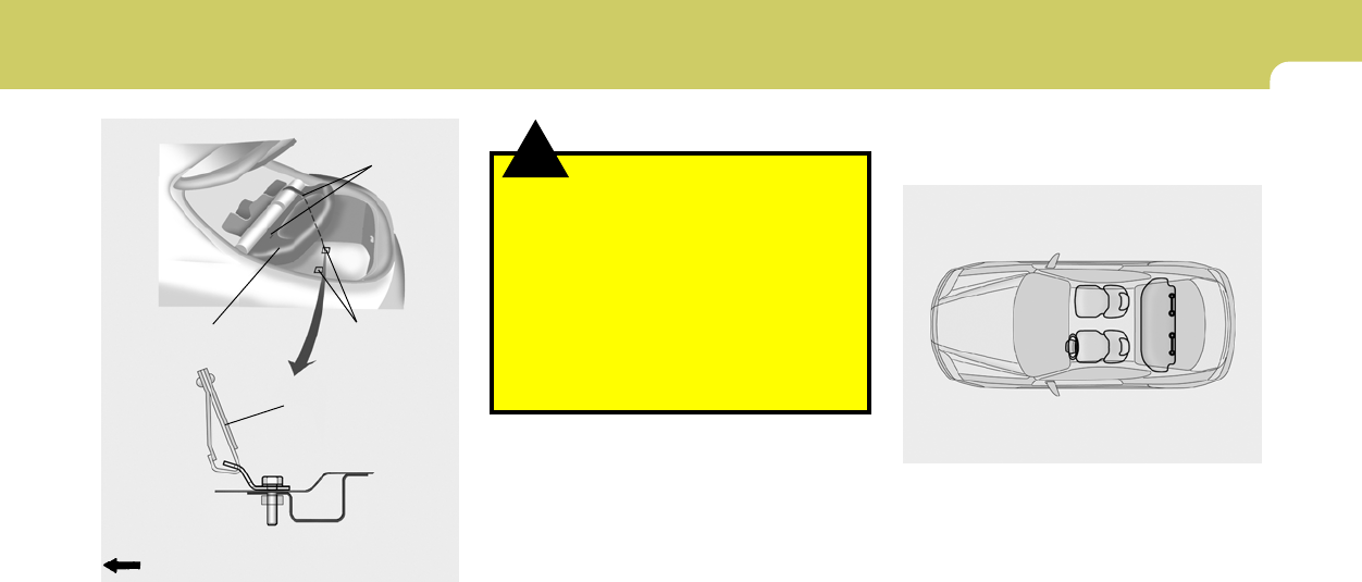
B230C05F-AAT
Installing a Child Restraint Seat with the
"Tether Anchorage" System
Two child restraint hook holders are located on
the luggage compartment floor.
To install the child restraint seat
B230E02GK
Tether Anchor Cover Child Restraint
Hook Holder
1. Open the tether anchor cover on the rear
luggage compartment floor.
2. Route the child restraint seat strap over the
seatback.
For vehicles with adjustable headrests, route
the tether strap under the headrest and
between the headrest posts, otherwise route
the tether strap over the top of the seatback.
1
FEATURES OF YOUR HYUNDAI
23
!
B230D03GK-AAT
Securing the child Restraint seat with
the "ISOFIX" system
Some child seat manufacturers make child
restraint seats that are labeled as ISOFIX or
ISOFIX-compatible child restraint seats. These
seats include two rigid or webbing mounted
attachments that connect to two ISOFIX an-
chors at specific seating positions in your ve-
hicle. This type of child restraint seat eliminates
the need to use seat belts to attach the child seat
for forward-facing child restraint seats.
ISOFIX anchors have been provided in your
vehicle. The ISOFIX anchors are located in the
left and right outboard rear seating positions.
Their locations are shown in the illustration.
B230F01GK
WARNING:
o A child can be seriously injured or killed
in a collision if the child restraint is not
properly anchored. Always follow the
child seat manufacturer’s instructions
for installation and use.
o Never mount more than one child re-
straint to a single tether or to a single
lower anchorage point. The increased
load caused by multiple seats may cause
the tethers or anchorage points to break,
causing serious injury or death.
B230E01GK
Covering shelf
Front of Vehicle
Tether strap hook
Blanking covers
Rear luggage compartment floor
3. Remove the blanking covers on the cover-
ing shelf.
4. Connect the tether strap hook to the child
restraint hook holder through the hole on the
covering shelf and tighten to secure the seat.
Child Restraint
Hook Holders
1FEATURES OF YOUR HYUNDAI
24
!WARNING:
o There is no center rear seat position.
o A child can be seriously injured or killed
in a collision if the child restraint is not
properly anchored. Always follow the
child seat manufacturer’s instructions
for installation and use.
o Never install a child restraint using the
ISOFIX anchors at the center position of
the rear seat. In a crash, the ISOFIX
anchors may break if a car seat is improp-
erly placed in the center position result-
ing in serious or fatal injuries. Only place
a ISOFIX or ISOFIX-compatible child seat
in the left or right out-board rear seating
positions (as shown) to the appropriate
ISOFIX anchors provided.
o Never mount more than one child re-
straint to a single tether or to a single
lower anchorage point. The increased
load caused by multiple seats may cause
the tethers or anchorage points to break,
causing serious injury or death.
o When using the vehicle’s “ISOFIX” sys-
tem to install a child restraint system in
the rear seat, all unused vehicle rear seat
belt metal latch plates or tabs must be
latched securely in their seat belt buck-
les and the seat belt webbing must be
retracted behind the child restraint to
prevent the child from reaching and tak-
ing hold of unretracted seat belts.
Unlatched metal latch plates or tabs may
allow the child to reach the unretracted
seat belts which may result in strangu-
lation and a serious injury or death to the
child in the child restraint.
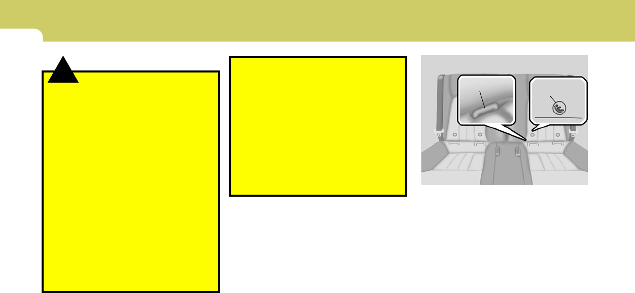
The ISOFIX anchors are located between the
seatback and the seat cushion of the rear seat
left and right outboard seating positions.
B230D02GK
ISOFIX Anchor ISOFIX Anchor
Position Indicator
1
FEATURES OF YOUR HYUNDAI
25
!
HGK261
B230G02O-AAT
Child Restraint System Installation on
outboard Rear Seats
To install a child restraint system in the outboard
rear seats, extend the shoulder/lap belt entirely
from its retractor until a "click" is felt. This will
engage the seat belt retractor automatic locking
feature, which allows the seat belt to retract but
not extend. Install the child restraint system,
buckle the seat belt and allow the seat belt to
take up any slack. Make sure that the lap portion
of the belt is tight around the child restraint
system and the shoulder portion of the belt is
positioned so that it can not interfere with the
child's head or neck. Also, double check to be
sure that the retractor has engaged the auto-
matic locking feature by trying to extend web-
bing out of the retractor.
On outboard rear seats
HGK1010
Follow the child seat manufacturer's instruc-
tions to properly install child restraint seats with
ISOFIX or ISOFIX-compatible attachments.
Once you have installed the ISOFIX child re-
straint, assure that the seat is properly attached
to the ISOFIX and tether anchors. Also, test the
child restraint seat before you place the child in
it. Tilt the seat from side to side. Also try to tug
the seat forward. Check to see if the anchors
hold the seat in place.
WARNING:
A child can be seriously injured or killed in
a collision if the child restraint is not prop-
erly anchored to the car and the child is not
properly restrained in the child restraint.
Always follow the child seat manufacturer’s
instructions for installation and use.
1FEATURES OF YOUR HYUNDAI
26
B180B04GK-AAT
Pre-tensioner Seat Belt (If Installed)
Your Hyundai vehicle is equipped with driver's
and front passenger's pre-tensioner seat belts.
The purpose of the pre-tensioner is to make
sure that the seat belts fit tightly against the
occupant's body in certain frontal collisions.
The pre-tensioner seat belts can be activated
alone or, where the frontal collision is severe
enough, together with the airbags.
When the vehicle stops suddenly, or if the
occupant tries to lean forward too quickly, the
seat belt retractor will lock into position. In
certain frontal collisions, the pre-tensioner will
activate and pull the seat belt into tighter contact
against the occupant's body.
HXG229
!WARNING:
o If the retractor is not in the Automatic
Locking mode, the child restraint can
move when your vehicle turns or stops
suddenly. A child can be seriously in-
jured or killed if the child restraint is not
properly anchored to the car, including
setting the retractor to the Automatic
Locking mode.
o Do not install any child restraint system
in the front passenger seat. Should an
accident occur and cause the passenger
side airbag to deploy, it could severely
injure or kill an infant or child seated in
an infant or child seat. Therefore, only
use a child restraint system in the rear
seat of your vehicle.
If the retractor is in the automatic locking mode,
the belt will be locked. After installation of the
child restraint system, try to move it in all
directions to be sure the child restraint system
is securely installed. If you need to tighten the
belt, pull more webbing toward the retractor.
When you unbuckle the seat belt and allow it to
retract, the retractor will automatically revert
back to its normal seated passenger emer-
gency locking usage condition.
NOTE:
o Before installing the child restraint sys-
tem in any seating position, read the
instructions supplied by the child re-
straint system manufacturer.
o If the seat belt does not operate as de-
scribed, have the system checked imme-
diately by your authorized Hyundai
dealer.
1
FEATURES OF YOUR HYUNDAI
27
The seat belt pre-tensioner system consists
mainly of the following components.
Their locations are shown in the illustration.
1. SRS airbag warning light
2. Seat belt pre-tensioner assembly
3. SRS control module
Driver's airbag
B180B01GK
2
3
Passenger's
airbag
1!WARNING:
To obtain maximum benefit from a pre-
tensioner seat belt:
o The seatbelt must be work correctly and
adjusted to the proper position (see
pages 1-18). Please read and follow all of
the important information and precau-
tions about your vehicle’s occupant
safety features – including seat belts –
that are provided in this manual.
o Be sure you and your passengers always
wear seat belts and wear them properly.
NOTE:
o Both the driver's and front passenger's
pre-tensioner seat belts will be activated
in certain frontal collisions. The pre-
tensioner seat belts can be activated
alone or, where the frontal collision is
severe enough, together with the
airbags.
o When the pre-tensioner seat belts are
activated, a loud noise may be heard and
fine dust, which may appear to be smoke,
may be visible in the passenger com-
partment. These are normal operating
conditions and are not hazardous.
o Although it is harmless, the fine dust
may cause skin irritation and should not
be breathed for prolonged periods. Wash
all exposed skin areas thoroughly after
an accident in which the pre-tensioner
seat belts were activated.
1FEATURES OF YOUR HYUNDAI
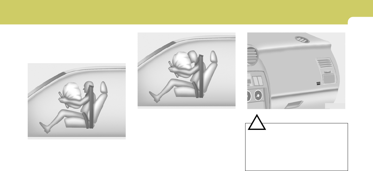
28 SUPPLEMENTAL RESTRAINT
(AIRBAG) SYSTEM (SRS)
B240A03GK-AAT
Your Hyundai is equipped with a Supplemental
Restraint (Airbag) System. The indications of
the system's presence are the letters "SRS AIR
BAG" embossed on the ornament in the steer-
ing wheel and the passenger's side front panel
pad above the glove box.
The Hyundai SRS consists of airbags installed
under the pad covers in the center of the
steering wheel and the passenger's side front
panel above the glove box. The purpose of the
SRS is to provide the vehicle's driver and/or the
front passenger with additional protection than
that offered by the seat belt system alone, in
case of a frontal impact of sufficient severity.
B240A01GK
Driver's Airbag
!WARNING:
o Pre-tensioners are designed to operate
only one time. After activation, pre-
tensioner seat belts must be replaced.
All seat belts, of any type, should always
be replaced after they have been worn
during a collision.
o The pre-tensioner seat belt assembly
mechanisms become hot during activa-
tion. Do not touch the pre-tensioner seat
belt assemblies for several minutes after
they have been activated.
o Do not attempt to inspect or replace the
pre-tensioner seat belts yourself. This
must be done by an authorized Hyundai
dealer.
o Do not strike the pre-tensioner seat belt
assemblies.
o Do not attempt to service or repair the
pre-tensioner seat belt system in any
manner.
o Improper handling of the pre-tensioner
seat belt assemblies, and failure to heed
the warnings to not strike, modify, in-
spect, replace, service or repair the pre-
tensioner seat belt assemblies may lead
to improper operation or inadvertent
activation and serious injury.
o Always wear seat belts when driving or
riding in a motor vehicle.
CAUTION:
o The sensor that activates the SRS airbag
is connected with the pre-tensioner seat
belts. The SRS airbag warning light on
the instrument panel will illuminate for
approximately 6 seconds after the igni-
tion key has been turned to the "ON"
position, and then it should turn off.
o If the pre-tensioner seat belt is not work-
ing properly, this warning light will illu-
minate even if there is no malfunction of
the SRS airbag system. If the SRS airbag
warning light does not illuminate when
the ignition key is turned to "ON" or if it
remains illuminated after approximately
6 seconds, or if it illuminates while the
vehicle is being driven, please have an
authorized Hyundai dealer inspect the
pre-tensioner seat belts and SRS airbag
system as soon as possible.
!
AIR
BAG
1
FEATURES OF YOUR HYUNDAI
29
!
NOTE:
o Be sure to read information about the
SRS on the labels provided on the front
of the sun visor and in the glove box.
o If you are considering modification of
your vehicle due to a disability, please
contact the Hyundai Customer Assis-
tance Center at 1-800-633-5151.
WARNING:
Always use seat belts and child restraints –
every trip, every time, everyone! Airbags
inflate with considerable force and in the
blink of an eye. Seat belts help keep occu-
pants in proper position to obtain maxi-
mum benefit from the airbag. Always fol-
low the precautions about seat belts, airbags
and occupant safety contained in this
manual.
To reduce the chance of serious or fatal
injuries and receive the maximum safety
benefit from your restraint system:
o Never place a child in any child or booster
seat in the front seat (see child restraints
1-21).
o ABC – Always Buckle Children in the
back seat. It is the safest place for
children of any age to ride
o Front and side impact airbags can injure
occupants improperly positioned in the
front seats
!
o The SRS is designed to deploy the
airbags only when an impact is suffi-
ciently severe and when the impact angle
is less than 30° from the forward longi-
tudinal axis of the vehicle and will not
deploy in side, rear or rollover impacts.
Additionally, the airbags will only de-
ploy once. Thus, seat belts must be worn
at all times.
o Front airbags are not intended to deploy
in light collisions in which protection
can be provided by the seat belt alone.
WARNING:
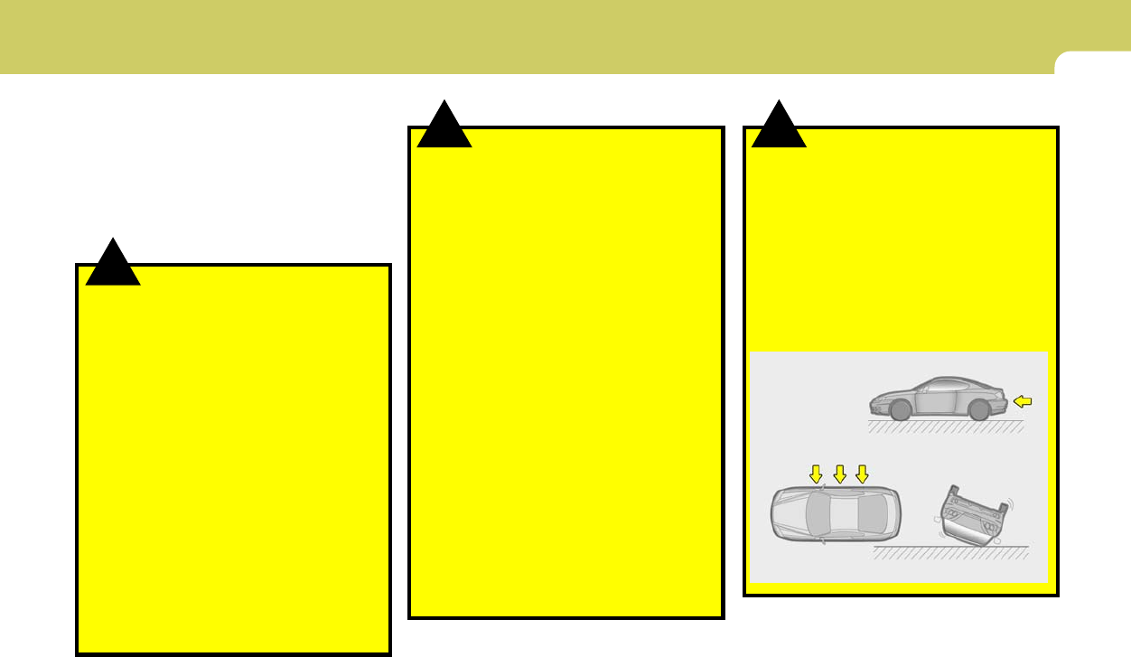
Rear impact
B240A02GK
Side Impact Rollover
!WARNING:
o Move your seat as far back as practical
from the front airbags, while still main-
taining control of the vehicle.
o Never sit or lean unnecessarily close to
the front or side airbags
o Never lean against the door or center
console – always sit in an upright posi-
tion
o Never place objects over or near any
airbag module (front or side impact
airbags), because these objects can in-
jure passengers in a crash
o Never place covers, blankets or after-
market seat warmers on the passenger
seat as these may interfere with the
occupant classification system
o Do not tamper or disconnect SRS wiring
or other components. Injuries could
result from inadvertent deployment or
failure of the airbag to deploy in a crash.
o If the SRS airbag warning light (see pg 1-
40) remains illuminated while the vehicle
is being driven, have an authorized
Hyundai dealer inspect the airbag sys-
tem as soon as possible.
o Airbags can only be used once – have an
authorized Hyundai dealer replace the
airbag immediately after deployment.
1FEATURES OF YOUR HYUNDAI
30
B240B04GK-AAT
SRS Components and Functions
The SRS consists of the following components:
- Driver's Airbag Module
- Passenger's Airbag Module
- Knee Bolster
- SRS Service Reminder Indicator (SRI)
- SRS Control Module (SRSCM)
The SRSCM continually monitors all elements
while the ignition is "ON" to determine if a frontal
or near-frontal impact is severe enough to
require airbag deployment.
B240B01L
o Front airbags are not intended to deploy
in side-impact, rear-impact or rollover
crashes. In addition, airbags will not
deploy in frontal crashes below the de-
ployment threshold speed.
o Move your seat as far back as practical
from the front airbags, while still main-
taining control of the vehicle. You and
your passengers should never sit or lean
unnecessarily close to the airbags. Im-
properly positioned drivers and passen-
gers can be severely injured by inflating
airbags.
o No objects should be placed over or near
the airbag modules on the steering
wheel, instrument panel, and the front
passenger's panel above the glove box,
because any such object could cause
harm if the vehicle is in a crash severe
enough to cause the airbags to deploy.
o If the airbags deploy, they must be re-
placed by an authorized Hyundai dealer.
Deployed airbags WILL NOT inflate again
and will provide no protection in subse-
quent collisions.
o Do not tamper with or disconnect SRS
wiring, or other components of the SRS
system. Doing so could result in injury,
due to accidental firing of the airbags or
by rendering the SRS inoperative.
!WARNING: !
o Do not install a child restraint system in
the front passenger seat position. A
child restraint system must never be
placed in the front seat. The infant or
child could be severely injured or killed
by an airbag deployment in case of an
accident.
o Do not allow children to ride in the front
passengrer seat. If older children (teen-
agers and older) must ride in the front
seat, make sure they are always properly
belted and that the seat is moved back as
far as possible.
o For maximum safety protection in all
types of crashes, all occupants includ-
ing the driver should always wear their
seat belts whether or not an airbag is
also provided at their seating position to
minimize the risk of severe injury or
death in the event of a crash. Do not sit
or lean unnecessarily close to the airbag
while the vehicle is in motion.
o The SRS airbag system must deploy very
rapidly to provide protection in a crash.
If an occupant is out of position because
of not wearing a seat belt, the airbag may
forcefully contact the occupant causing
serious or fatal injuries.
WARNING:
1
FEATURES OF YOUR HYUNDAI
31
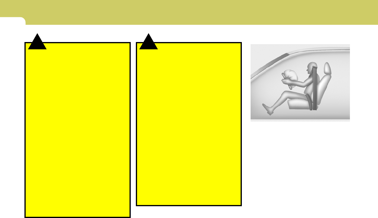
A fully inflated airbag in combination with a
properly worn seat belt slows the driver's or the
passenger's forward motion, thus reducing the
risk of head and chest injury.
After complete inflation, the airbag immediately
starts deflating, enabling the driver to maintain
forward visibility.
B240B03L
B240B02L
The SRS service reminder indicator (SRI) on
the instrument panel will illuminate for about 6
seconds after the ignition key is turned to the
"ON" position or after the engine is started, after
which the SRI should go out.
The airbag modules are located both in the
center of the steering wheel and in the front
passenger's panel above the glove box. When
the SRSCM detects a considerable impact to
the front of the vehicle, it will automatically
deploy the airbags.
Upon deployment, tear seams molded directly
into the pad covers will separate under pres-
sure from the expansion of the airbags. Further
opening of the covers then allows full inflation of
the airbags.
Passanger's Airbag
B240B01GK
!CAUTION:
Do not install or place any accessories
(drink holder, cassette holder, sticker, etc)
on the front passenger's panel above the
glove box in a vehicle with a passenger's air
bag. Such objects may become dangerous
projectiles and cause injury if the
passenger's air bag inflates.
1FEATURES OF YOUR HYUNDAI
32
B990B05Y-AAT
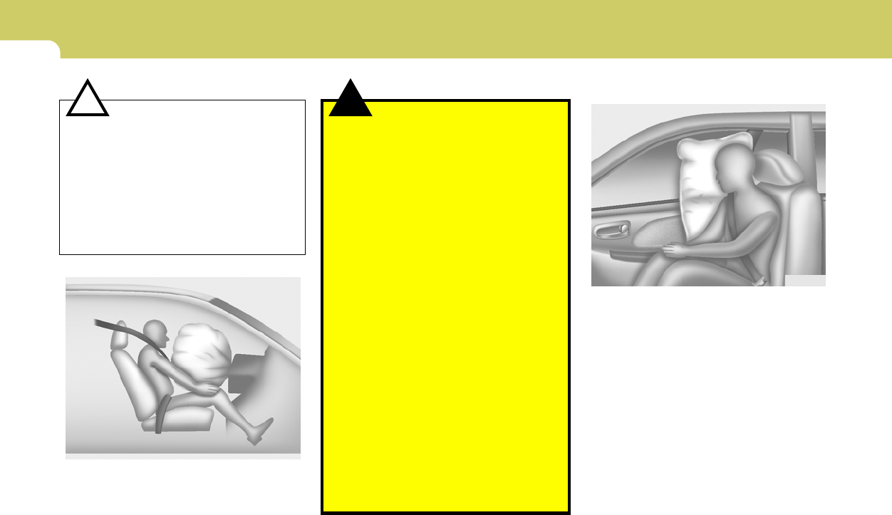
Side Impact Airbag (If installed)
Your Hyundai is equipped with a side impact
airbag in each front seat. The purpose of the
airbag is to provide the vehicle's driver and/or
the front passenger with additional protection
than that offered by the seat belt alone. The side
impact airbags are designed to deploy only
during certain side-impact collisions, depend-
ing on the crash severity, angle, speed and point
of impact. The side impact airbags are not
designed to deploy in all side impact situations.
B990B02Y
CAUTION:
When installing a container of liquid air
freshener inside a vehicle, do not place it
near the instrument cluster nor on the in-
strument panel pad surface. If there is any
leakage from the air freshener onto these
areas (instrument cluster, instrument panel
pad or air ventilator), it may damage these
parts. If the liquid from the air freshener
does leak onto these areas, wash them with
water immediately.
!!
B240B05L
WARNING:
o If an airbag deploys, there may be a loud
noise followed by a fine dust released in
the vehicle. These conditions are nor-
mal and are not hazardous - the airbags
are packed in this fine powder. The dust
generated during airbag deployment
may cause skin or eye irritation as well as
aggravate asthma for some persons.
Always wash all exposed skin areas thor-
oughly with lukewarm water and a mild
soap after an accident in which the
airbags were deployed.
o The SRS can function only when the
ignition key is in the "ON" position. If the
SRS SRI does not illuminute, or contin-
uously remains on after illuminating for
about 6 seconds when the ignition key
is turned to the "ON" position, or after
the engine is started, illuminates while
driving, the SRS is not working properly.
If this occurs, have your vehicle immedi-
ately inspected by your Hyundai dealer.
o Before you replace a fuse or disconnect
a battery terminal, turn the ignition key
to the "LOCK" position or remove the
ignition key. Never remove or replace the
air bag related fuse(s) when the ignition
key is in the "ON" position. Failure to
heed this warning will cause the SRS SRI
to illuminate.
Passanger's Airbag

1
FEATURES OF YOUR HYUNDAI
33
!
o Do not install any accessories on the
side or near the side impact airbag.
o Do not place any objects over the airbag
or between the airbag and yourself.
o Do not place any objects (an umbrella,
bag, etc.) between the front door and the
front seat. Such objects may become
dangerous projectiles and cause injury
if the supplemental side impact airbag
inflates.
o To prevent unexpected deployment of
the side impact airbag that may result in
personal injury,avoid impact to the side
airbag sensor when the ignition key is
on.
WARNING:
!WARNING:
o The side impact airbag is supplemental
to the driver's and the passenger's seat
belt systems and is not a substitute for
them. Therefore your seat belts must be
worn at all times while the vehicle is in
motion. The airbags deploy only in cer-
tain side impact conditions severe
enough to cause significant injury to the
vehicle occupants.
o For best protection from the side impact
airbag system and to avoid being injured
by the deploying side impact airbag,
both front seat occupants should sit in
an upright position with the seat belt
properly fastened. The driver's hands
should be placed on the steering wheel
at the 9:00 and 3:00 o'clock positions.
The passenger's arms and hands should
be placed on their laps.
o Do not use any accessory seat covers.
o Use of seat covers could prevent or
reduce the effectiveness of the system.
B240C04A-AAT
SRS Care
o The SRS is virtually maintenance free and
there are no parts you can safely service by
yourself. If the SRS SRI (Service Reminder
Indicator) does not illuminate, or continu-
ously remains on, have your vehicle imme-
diately inspected by your Hyundai dealer.
o Any work on the SRS system, such as
removing, installing, repairing, or any work
on the steering wheel must be performed by
a qualified Hyundai technician. Improper
handling of the airbag system may result in
serious personal injury.
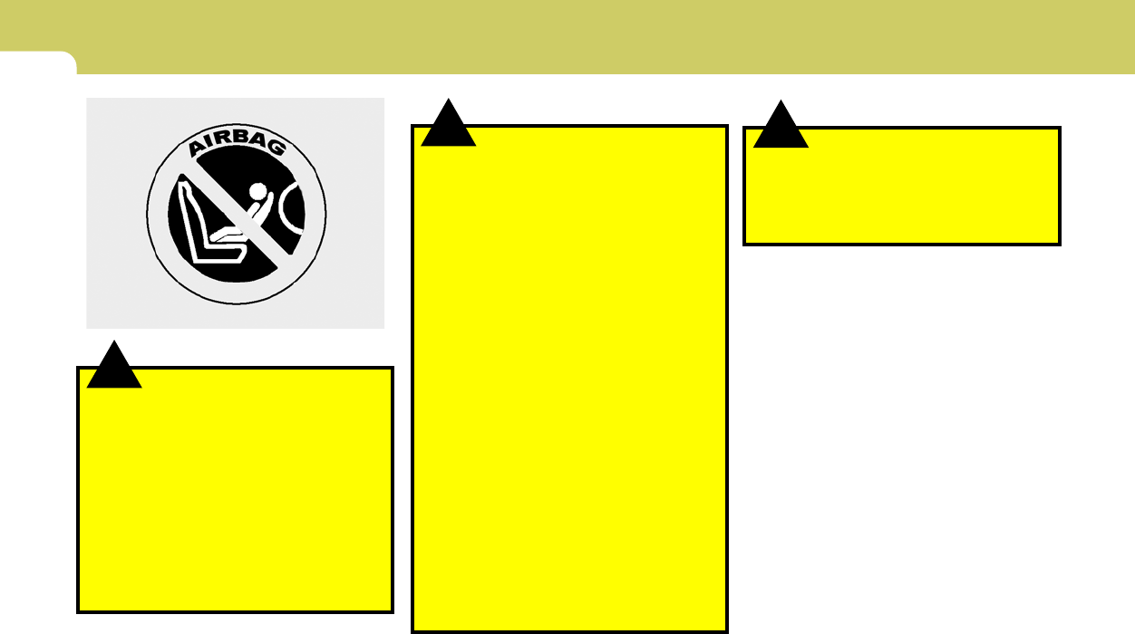
1FEATURES OF YOUR HYUNDAI
34
!
o If your car was flooded and has soaked
carpeting or water on the floor, you
shouldn't try to start the engine; have
the car towed to an authorized Hyundai
dealer.
WARNING:
!WARNING:
o Do not install a child restraint system in
the front passenger seat position. A
child restraint system must never be
placed in the front seat. The infant or
child could be severely injured or killed
by an airbag deployment in case of an
accident.
o Modification to SRS components or wir-
ing, including the addition of any kind of
badges to the pad covers or modifica-
tions to the body structure, can ad-
versely affect SRS performance and lead
to possible injury.
B240C01HP
!
o For cleaning the airbag pad covers, use
only a soft, dry cloth or one which has
been moistened with plain water. Sol-
vents or cleaners could adversely affect
the airbag covers and proper deploy-
ment of the system.
o No objects should be placed over or near
the airbag modules on the steering
wheel, instrument panel, and the front
passenger’s panel above the glove box,
because any such object could cause
harm if the vehicle is in a crash severe
enough to cause the airbags to inflate.
o If the airbags inflate, they must be re-
placed by an authorized Hyundai dealer.
o Do not tamper with or disconnect SRS
wiring, or other components of the SRS
system. Doing so could result in injury,
due to accidental inflation of the airbags
or by rendering the SRS inoperative.
o If components of the airbag system must
be discarded, or if the vehicle must be
scrapped, certain safety precautions
must be observed. Your Hyundai dealer
knows these precautions and can give
you the necessary information. Failure
to follow these precautions and proce-
dures could increase the risk of personal
injury.
WARNING:

1
FEATURES OF YOUR HYUNDAI
35
B240D02JM-AAT
Additional Safety Precautions
oNever let passengers ride in the cargo
area (trunk) or on top of a folded-down
back seat. All occupants should sit upright,
fully back in their seats with their seat belts
on and their feet on the floor.
oPassengers should not move out of or
change seats while the vehicle is mov-
ing. A passenger who is not wearing a seat
belt during a crash or emergency stop can
be thrown against the inside of the vehicle,
against other occupants, or out of the ve-
hicle.
oEach seat belt is designed to restrain one
occupant. If more than one person uses the
same seat belt, they could be seriously
injured or killed in a collision.
oDo not use any accessories on seat
belts. Devices claiming to improve occu-
pant comfort or reposition the seat belt can
reduce the protection provided by the seat
belt and increase the chance of serious
injury in a crash.
oPassengers should not place hard or
sharp objects between themselves and
the airbags. Carrying hard or sharp objects
on your lap or in your mouth can result in
injuries if an airbag inflates.
oKeep occupants away from the airbag
covers. All occupants should sit upright, fully
back in their seats with their seat belts on and
their feet on the floor. If occupants are too
close to the airbag covers, they could be
injured if the airbags inflate.
oDo not attach or place objects on or near
the airbag covers. Any object attached to
or placed on the front or side impact airbag
covers could interfere with the proper opera-
tion of the airbags.
oDo not modify the front seats. Modifica-
tion of the front seats could interfere with the
operation of the supplemental restraint sys-
tem sensing components or side impact
airbags.
oDo not place items under the front seats.
Placing items under the front seats could
interfere with the operation of the supple-
mental restraint system sensing compo-
nents and wiring harnesses.
oNever hold an infant or child on your lap.
The infant or child could be seriously injured
or killed in the event of a crash. All infants and
children should be properly restrained in
appropriate child safety seats or seat belts
in the rear seat.
WARNING:
o Sitting improperly or out of position can
cause occupants to be shifted too close
to a deploying airbag, strike the interior
structure or be thrown from the vehicle
resulting in serious injury or death.
o Always sit upright with the seatback in
an upright position, centered on the
seat cushion with your seat belt on, legs
comfortably extended and your feet on
the floor.
Adding Equipment to or Modifying Your
Airbag-Equipped Vehicle.
If you modify your vehicle by changing your
vehicle's frame, bumper system, front end or
side sheet metal or ride height, this may affect
the operation of your vehicle's airbag system.
!
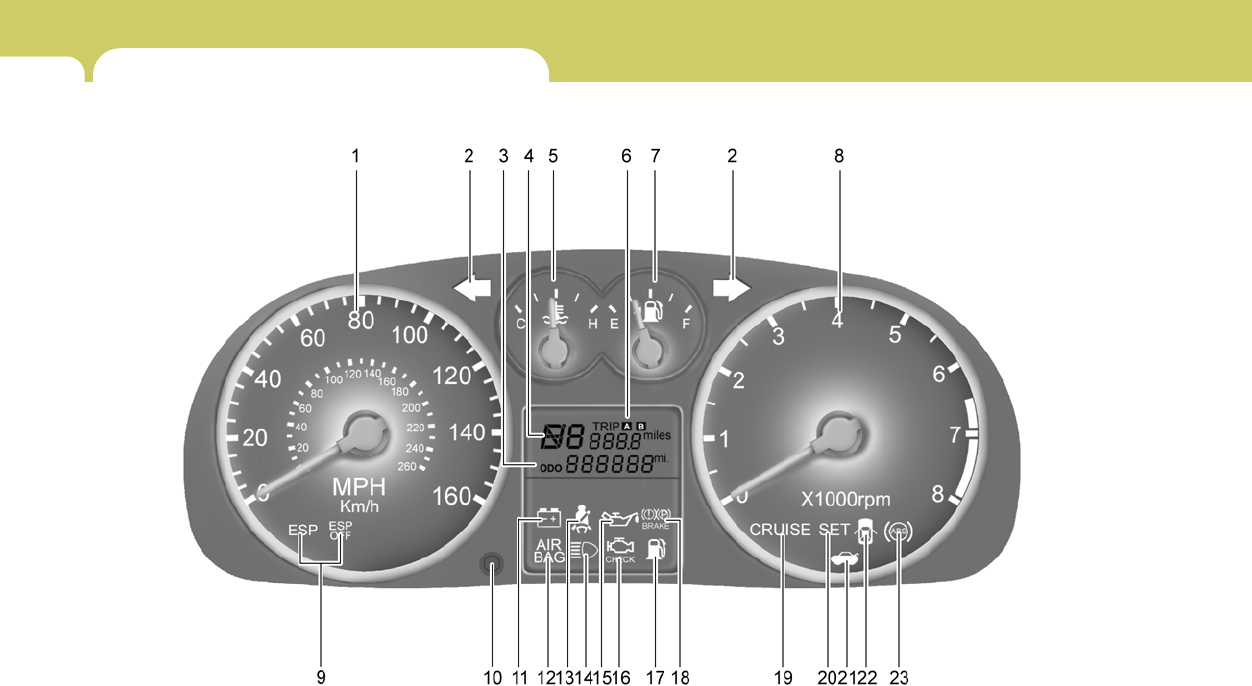
1FEATURES OF YOUR HYUNDAI
36 INSTRUMENT CLUSTER AND INDICATOR LIGHTS
B260A02GK-AAT
B260A02GK-A

1
FEATURES OF YOUR HYUNDAI
37
1. Speedometer
2. Turn Signal Indicator Light
3. Odometer
4. Automatic Transaxle Position Indicator Light (If installed)
5. Coolant Temperature Gauge
6. Trip odometer
7. Fuel Gauge
8. Tachometer
9. Electronic Stability Program (ESP) Indicator Light (If installed)
10. Trip Odometer Reset Knob
11. Charging System Warning Light
12. Supplemental Restraint System (SRS) Service Reminder
Indicator (SRI)
13. Seat Belt Warning Light
14. High Beam Indicator Light
15. Low Oil Pressure Warning Light
16. Malfunction Indicator Light (MIL)
17. Low Fuel Warning Light
18. Parking Brake/Low Brake Fluid Level Warning Light
19. CRUISE Indicator Light (If installed)
20. CRUISE SET Indicator Light (If installed)
21. Tail Gate Open Warning Light
22. Door Ajar Warning Light
23. ABS Service Reminder Indicator (SRI) (If installed)
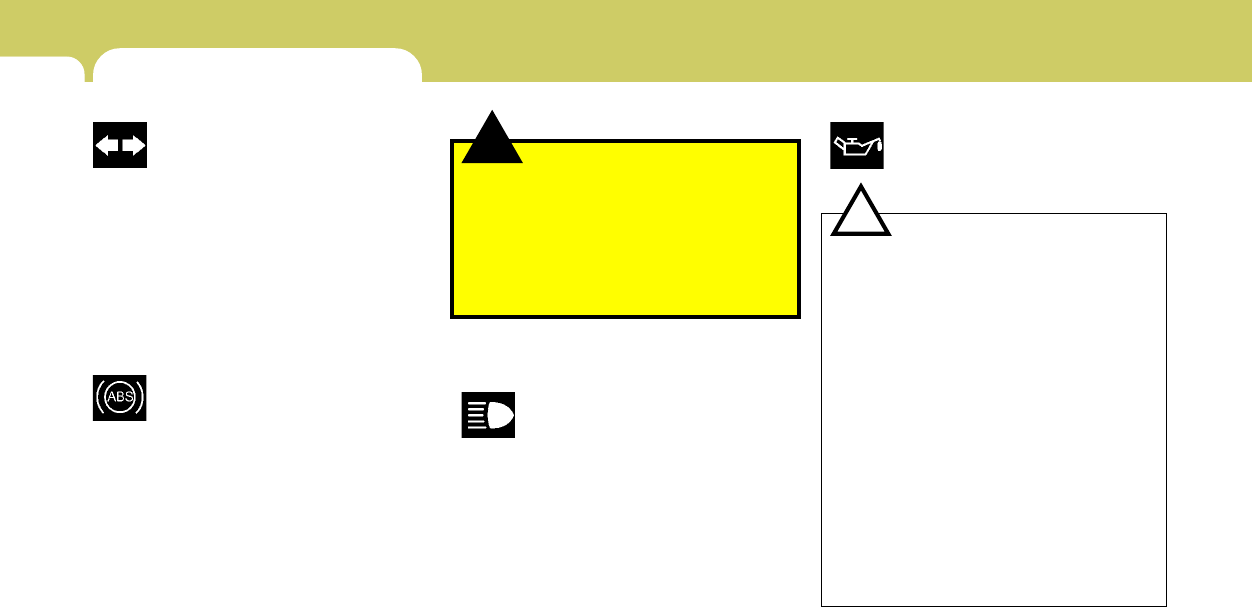
1FEATURES OF YOUR HYUNDAI
38
B260G01A-AAT
Low Oil Pressure Warning Light
CAUTION:
If the oil pressure warning light stays on
while the engine is running, serious engine
damage may result. The oil pressure warn-
ing light comes on whenever there is insuf-
ficient oil pressure. In normal operation, it
should come on when the ignition switch
is turned on, then go out when the engine
is started. If the oil pressure warning light
stays on while the engine is running, there
is a serious malfunction.
If this happens, stop the car as soon as it is
safe to do so, turn off the engine and check
the oil level. If the oil level is low, fill the
engine oil to the proper level and start the
engine again. If the light stays on with the
engine running, turn the engine off imme-
diately. In any instance where the oil light
stays on when the engine is running, the
engine should be checked by a Hyundai
dealer before the car is driven again.
!
!
WARNING AND INDICATOR LIGHTS
B260P02Y-GAT
ABS Service Reminder Indica-
tor (SRI) (If Installed)
When the key is turned to the "ON" position, the
Anti-Lock Brake System SRI will come on and
then go off in a few seconds. If the ABS SRI
remains on, comes on while driving, or does not
come on when the key is turned to the "ON"
position, this indicates that there may be a
problem with the ABS.
If this occurs, have your vehicle checked by
your Hyundai dealer as soon as possible. The
normal braking system will still be operational,
but without the assistance of the anti-lock brake
system.
WARNING:
If the both ABS SRI and Parking Brake/
Brake fluid level warning lights remain "ON"
or come on while driving, there may be a
problem with E.B.D (Electronic Brake Force
Distribution).
If this occurs, avoid sudden stops and have
your vehicle checked by your Hyundai dealer
as soon as possible.
B260D01A-AAT
Turn Signal Indicator Lights
The blinking green arrows on the instrument
panel show the direction indicated by the turn
signals. If the arrow comes on but does not blink,
blinks more rapidly than normal, or does not
illuminate at all, a malfunction in the turn signal
system is indicated. Your dealer should be
consulted for repairs.
B260F01A-AAT
High Beam Indicator Light
The high beam indicator light comes on when-
ever the headlights are switched to the high
beam or flash position.

1
FEATURES OF YOUR HYUNDAI
39
B260H01GK-AAT
Parking Brake/Low Brake Fluid
Level Warning Light
CAUITON:
If you suspect brake trouble, have your
brakes checked by a Hyundai dealer as
soon as possible. Driving your car with a
problem in either the brake electrical sys-
tem or brake hydraulic system is danger-
ous, and could result in a serious injury or
death.
Warning Light Operation
The parking brake/low brake fluid level warning
light should come on when the parking brake is
applied and the ignition switch is turned to "ON"
or "START". After the engine is started, the light
should go out in three seconds.
If the parking brake is not applied, the warning
light should come on when the ignition switch is
turned to "ON" or "START", then go out in three
seconds. If the light comes on at any other time,
you should slow the vehicle and bring it to a
complete stop in a safe location off the roadway.
The brake fluid level warning light indicates that
the brake fluid level in the brake master cylinder
is low and hydraulic brake fluid conforming to
DOT 3 or DOT 4 specifications should be
added. After adding fluid, if no other trouble is
found, the car should be immediately and care-
fully driven to a Hyundai dealer for inspection.
If further trouble is experienced, the vehicle
should not be driven at all but taken to a dealer
by a professional towing service.
Your Hyundai is equipped with dual-diagonal
braking systems. This means you still have
braking on two wheels even if one of the dual
systems should fail. With only one of the dual
systems working, more than normal pedal travel
and greater pedal pressure are required to stop
the car. Also, the car will not stop in as short a
distance with only half of the brake system
working. If the brakes fail while you are driving,
shift to a lower gear for additional engine braking
and stop the car as soon as it is safe to do so.
!
B260J01A-AAT
Charging System Warning Light
The charging system warning light should come
on when the ignition is turned on, then go out
when the engine is running. If the light stays on
while the engine is running, there is a malfunc-
tion in the electrical charging system. If the light
comes on while you are driving, stop, turn off the
engine and check under the hood. First, make
certain the generator drive belt is in place. If it is,
check the tension of the belt. Do this as shown
on page 6-23 by pushing down on the center of
the belt. Have the system checked by your
Hyundai dealer as soon as possible.
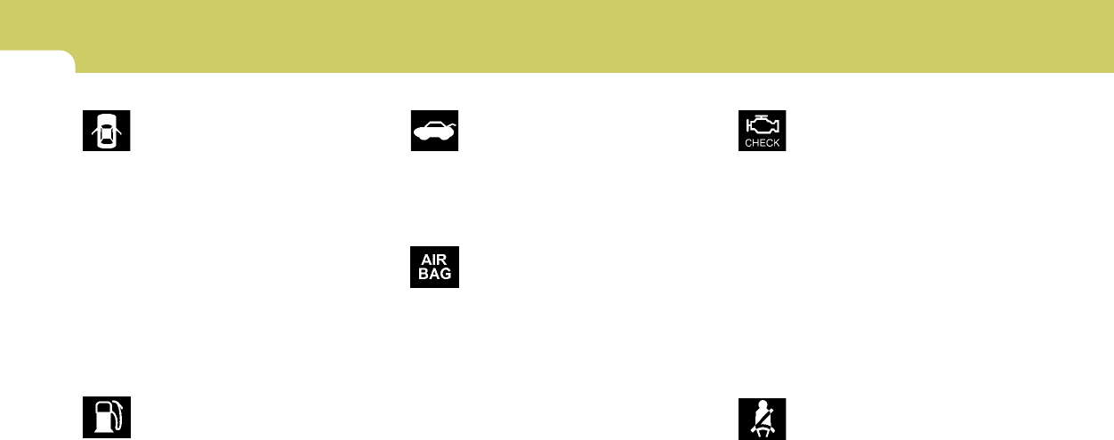
1FEATURES OF YOUR HYUNDAI
40
B260E01L-AAT
Seat Belt Reminder Light And
Chime
Seat belt reminder light comes and stays on until
the seat belt is fastened when the ignition key is
turned "ON" or "START".
And, the warning chime will also sound for about
6 seconds.
B260K01F-AAT
Tail Gate Open Warning Light
This light remains on unless the tail gate is
completely closed and latched.
B260M01A-AAT
Low Fuel Level Warning Light
The low fuel level warning light comes on when
the fuel tank is approaching empty. When it
comes on, you should add fuel as soon as
possible. Driving with the fuel level warning light
on or with the fuel level below "E" can cause the
engine to misfire and damage the catalytic
converter.
B260L02HP-GAT
Door Ajar Warning Light and
Chime (If Installed)
The door ajar warning light warns you that a door
is not completely closed and the chime warns
you that the key is in the ignition switch.
NOTE :
The warning chime only sounds whenever
the key is in the ignition switch and the
driver's side front door is open simulta-
neously. The chime sounds until the key is
removed from the ignition switch or the
driver's side front door is closed.
B260B01JM-AAT
SRS (Airbag) Service
Reminder Indicator (SRI)
The SRS service reminder indicator (SRI) comes
on for about 6 seconds after the ignition key is
turned to the "ON" position or after the engine
is started, after which it will go out.
This light also comes on when the SRS is not
working properly. If the SRI does not come on,
or continuously remains on after coming on for
about 6 seconds when you turned the ignition
key to the "ON" position or started the engine,
or if it comes on while driving, have the SRS
inspected by an authorized Hyundai Dealer.
B260N02A-AAT
Malfunction Indicator
Light
This light illuminates when there is a malfunction
of an exhaust gas related component, and the
system is not functioning properly so that the
exhaust gas regulation values are not satisfied.
This light will also illuminate when the ignition key
is turned to the "ON" position, and then it will go
out in a few seconds after the engine is started.
If it illuminates while driving, or does not illumi-
nate when the ignition key is turned to the "ON"
position, take your car to your nearest autho-
rized Hyundai dealer and have the system
checked.

1
FEATURES OF YOUR HYUNDAI
41
B260Q01E-GAT
CRUISE Indicator Light
(If Installed)
The cruise indicator light in the instrument clus-
ter is illuminated when the cruise control main
switch on the end of the barrel is pushed.
The indicator light does not illuminate when the
cruise control main switch is pushed a second
time.
Information about the use of cruise control is
beginning on page 1-63.
B270A01A-AAT
BRAKE PAD WEAR WARNING SOUND
The front disc brake pads have wear indicators
that should make a high-pitched squealing or
scraping noise when new pads are needed. The
sound may come and go or be heard all the time
when the vehicle is moving. It may also be heard
when the brake pedal is pushed down firmly.
Excessive rotor damage will result if the worn
pads are not replaced. See your Hyundai dealer
immediately.
B260R01E-GAT
CRUISE SET Indicator Light
(If installed)
The set indicator light in the instrument cluster
is illuminated when the cruise control switch is
pushed downward to "SET (COAST)".
The set indicator light does not illuminate when
the control switch is in the "CANCEL" position.
B265C01LZ-AAT
Electronic Stability
Program Indicator Lights
(If installed)
The electronic stability program indicators
change operation according to the ignition switch
position and whether the system is in operation
or not.
They will illuminate when the ignition key is
turned to the "ON" position, but should go out
after three seconds. If the ESP or ESP-OFF
indicator stays on, take your car to your autho-
rized Hyundai dealer and have the system
checked. See section 2 for more information
about the ESP.
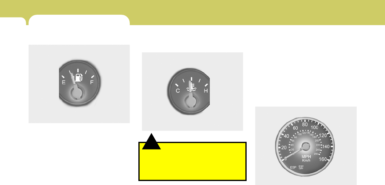
1FEATURES OF YOUR HYUNDAI
42
!
B290A02A-AAT
ENGINE COOLANT TEMPERATURE
GAUGE
WARNING:
Never remove the radiator cap when the
engine is hot. The engine coolant is under
pressure and could erupt and cause severe
burns. Wait until the engine is cool before
removing the radiator cap.
The needle on the engine coolant temperature
gauge should stay in the normal range. If it
moves across the dial to "H" (Hot), pull over and
stop as soon as possible and turn off the engine.
Then open the hood and after the engine has
cooled, check the coolant level and the water
pump drive belt. If you suspect cooling system
trouble, have your cooling system checked by
a Hyundai dealer as soon as possible.
B300A01A-AAT
SPEEDOMETER
Your Hyundai's speedometer is calibrated in
miles per hour (on the outer scale) and kilome-
ters per hour (on the inner scale).
HGK2060
HGK2058A
INSTRUMENT CLUSTER
B280A01A-AAT
FUEL GAUGE
The needle on the gauge indicates the approxi-
mate fuel level in the fuel tank. The fuel capacity
is given in Section 9.
HGK2059
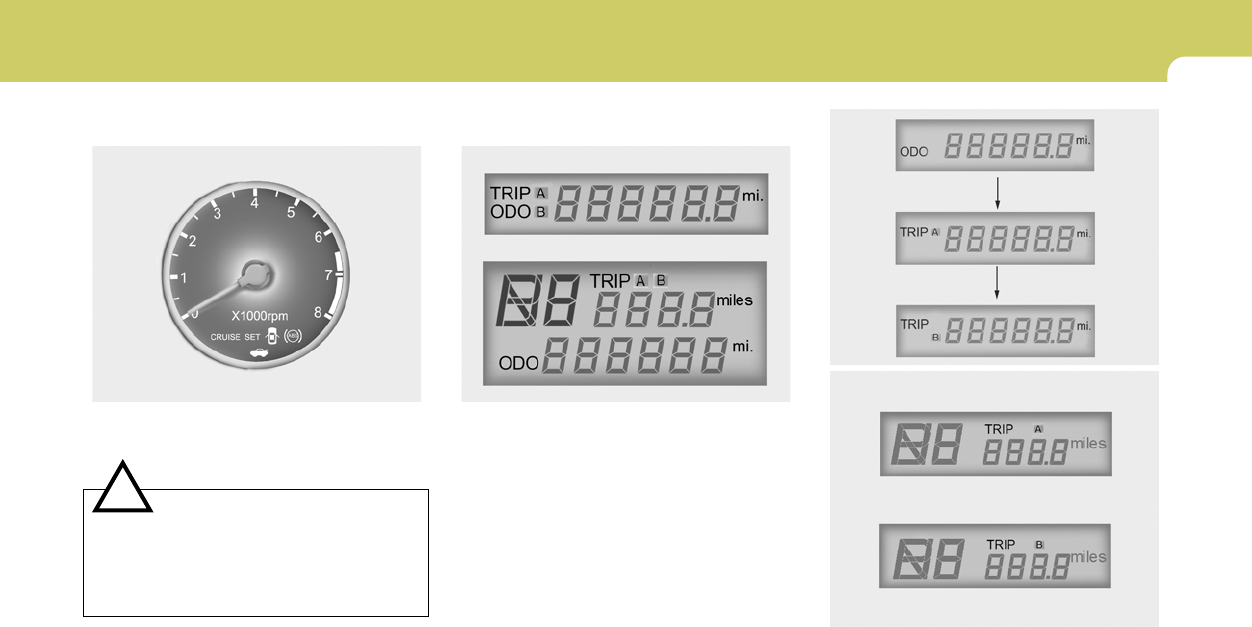
1
FEATURES OF YOUR HYUNDAI
43
!
B330A03E-AAT
TACHOMETER
The tachometer registers the speed of your
engine in revolutions per minute (rpm).
B330A01GK
CAUTION:
The engine should not be raced to such a
speed that the needle enters the red zone
on the tachometer face. This can cause
severe engine damage and may void your
warranty.
B310B01GK-AAT
Odometer/Trip odometer
Function of digital odometer/trip odom-
eter
Pushing in the reset switch on the right side of
speedometer when the ignition switch is turned
"ON" will display the following sequence:
HGK028B
Type A
Type B
HGK2061-1
HGK055C
Type A
Type B

1FEATURES OF YOUR HYUNDAI
44
1. Odometer
The odometer records the total driving distance
in miles, and is useful for keeping a record for
maintenance intervals.
NOTE:
Any alteration of the odometer may void
your warranty coverage.
2,3 Trip odometer
Records the distance of 2 trips in miles.
TRIP A: Distance you have traveled from your
origination point to a first destination.
TRIP B: Distance from the first destination to the
final destination.
To shift from TRIP A to TRIP B, press the reset
switch. When pressed for 1 second, it will reset
to 0.
TRIP COMPUTER
B400B02GK-GAT
(If installed)
The trip computer is a microcomputer-con-
trolled driver information gauge that displays
information related to driving, such as estimated
distance to empty, average speed and drive
time on the LCD.
Reset Switch
o The reset switch is used to zero the multi-
functional display mode.
o Pushing in the reset switch on the left side of
tacometer changes the display as follows;
DISTANCE TO EMPTY
AVERAGE SPEED
DRIVE TIME
B400B01GK-E
Type A
Type B
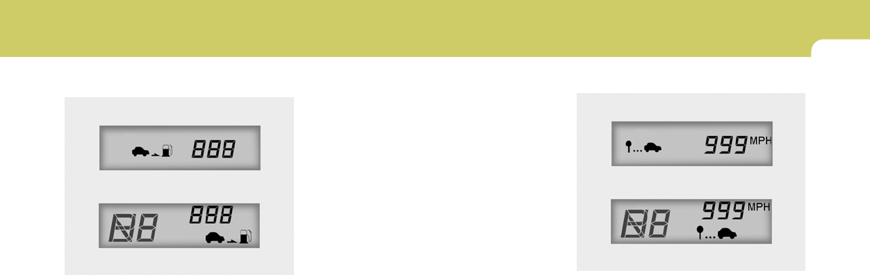
1
FEATURES OF YOUR HYUNDAI
45
1. Distance to Empty
o This mode provides the estimated distance
to empty from the current fuel level in the fuel
tank.
o The trip computer may not register additional
fuel if less than 6 liters of fuel are added to the
vehicle.
o When the battery has been reinstalled after
being discharged or disconnected, drive
more than 32km for an accurate distance to
empty.
HGK2063
Type A
Type B
NOTE:
o When the distance to empty is less than
50 km, the symbol will always come on
and the distance to empty digits will
indicate "---" with flash until more fuel
is added.
o The distance to empty can differ from
the actual tripmeter according to driving
conditions.
o The distance to empty can vary accord-
ing to the driving conditions, driving
pattern or vehicle speed.
B400B02GK-E
Type A
Type B
2. AVERAGE SPEED
o This mode indicates the average speed
travelled since the last average speed reset.
o To reset the average speed to zero, press
and hold the reset switch for more than 1
second while the average speed is being
displayed.
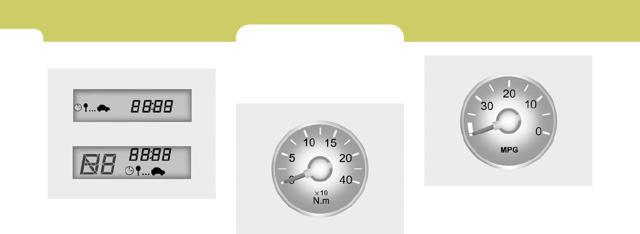
1FEATURES OF YOUR HYUNDAI
46 MULTI GAUGE
B330C01GK-GAT
(If installed)
Multi gauge is consists of torque gauge, instan-
taneous fuel consumption gauge and volt gauge.
B330C01GK
Torque gauge
It shows instantaneous change of the torque by
rpm.
Instantaneous fuel Consumption gauge
It shows instantaneous fuel consumption ac-
cording to the driving condition. The more indi-
cated figure is low, the more it indicates efficient
driving situation.
B330C04GK
3. DRIVE TIME
o This mode indicates the drive time travelled
since the last drive time reset.
o To reset the drive time to zero, press and
hold the reset switch for more than 1 second
while the drive time is being displayed.
HGK2065
Type A
Type B
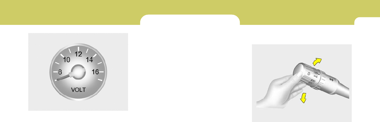
1
FEATURES OF YOUR HYUNDAI
47
Volt gauge
It shows moment volt change and makes for
diver correspond to low volt situation.
B330C03GK
MULTI-FUNCTION LIGHT SWITCH
B340A01A-AAT
COMBINATION TURN SIGNAL,
HEADLIGHT AND HIGH-BEAM
SWITCH
Turn Signal Operation
Pulling down on the lever causes the turn
signals on the left side of the car to blink. Pushing
upwards on the lever causes the turn signals on
the right side of the car to blink. As the turn is
completed, the lever will automatically return to
the center position and turn off the turn signals
at the same time. If either turn signal indicator
light blinks more rapidly than usual, goes on but
does not blink, or does not go on at all, there is
a malfunction in the system. Check for a burned-
out fuse or bulb or see your Hyundai dealer.
B340B01A-AAT
Lane Change Signal
To indicate a lane change, move the lever up or
down to a point where it begins flashing.
The lever will automatically return to the center
position when released.
HGK2079
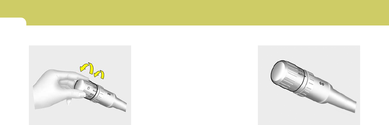
1FEATURES OF YOUR HYUNDAI
48
Parking light auto cut
o The purpose of this feature is to prevent the
battery from being discharged. The system
automatically turns off the small light when
the driver removes the ignition key and
opens the driver- side door.
o With this feature, the parklight will be turned
off automatically if the driver parks on the
side of road at night.
If necessary, to keep the lights on when the
ignition key is removed, perform the following :
1) Open the driver-side door.
2) Turn the parklights OFF and ON again using
the light switch on the steering column.
B340D01A-AAT
High-beam Switch
To turn on the headlight high beams, push the
lever forward (away from you). The high beam
indicator light will come on at the same time. For
low beams, pull the lever back toward you.
B340G01LZ-GAT
Auto Light (If installed)
To operate the automatic light feature, turn the
barrel on the end of the multi-function switch. If
you set the multi-function switch to "AUTO", the
tail lights and headlights will be turned automati-
cally on or off according to external illumination.
NOTE:
Switch on car light manually in foggy, cloudy
and rainy conditions.
HGK2075
B340C04E-AAT
Headlight Switch
To operate the headlights, turn the barrel on the
end of the multi-function switch. The first posi-
tion turns on the parking lights, sidelights, tail
lights and instrument panel lights. The second
position turns on the headlights.
NOTE:
The ignition must be in the "ON" position
to turn on the headlight.
HGK2074
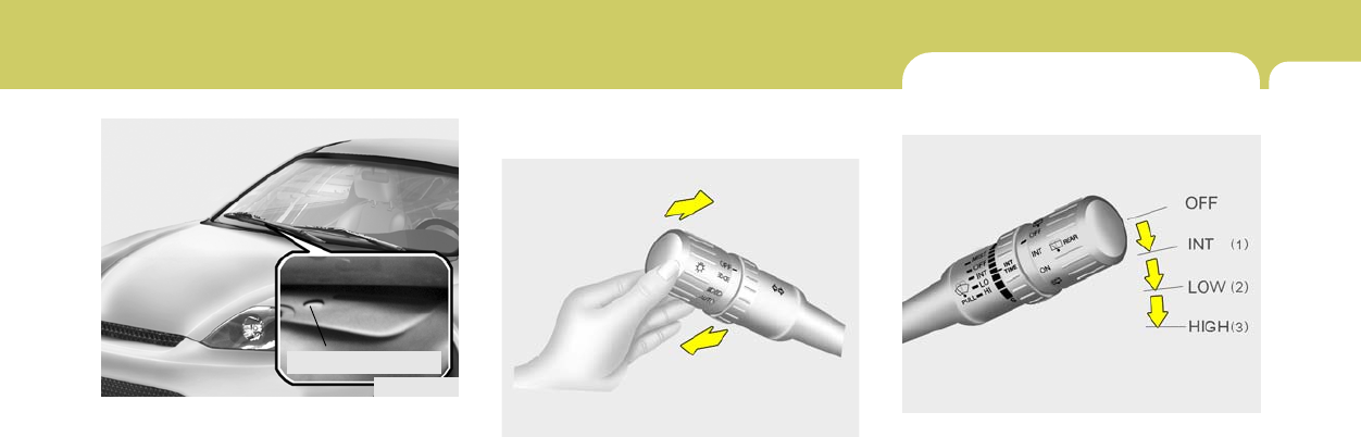
1
FEATURES OF YOUR HYUNDAI
49
B340E01A-AAT
Headlight Flasher
To flash the headlights, pull the switch lever
toward you, then release it. The headlights can
be flashed even though the headlight switch is
in the "OFF" position.
HGK2077
NOTE:
o Never place anything over sensor lo-
cated on the instrument panel, this will
ensure better auto light system control.
o Don't clean the sensor using a window
cleaner.
o If your vehicle has window tint or other
types of coating on the front windshield,
the AUTO light system may not work
properly.
B340G01GK
Auto Light Sensor
WINDSHIELD WIPER AND WASHER
SWITCH
B350A01A-AAT
The windshield wiper switch has three posi-
tions:
(1) Intermittent wiper operation
(2) Low-speed operation
(3) High-speed operation
NOTE:
To prevent damage to the wiper system, do
not attempt to wipe away heavy accumula-
tions of snow or ice. Accumulated snow
and ice should be removed manually. If
there is only a light layer of snow or ice,
operate the heater in the defrost mode to
melt the snow or ice before using the wiper.
HGK042A
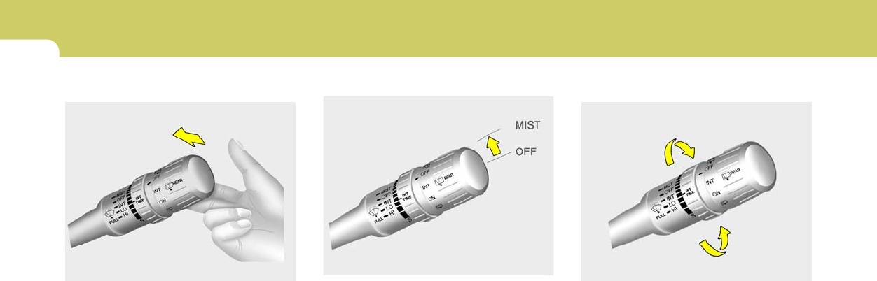
1FEATURES OF YOUR HYUNDAI
50
B350B01O-AAT
Windshield Washer Operation
To use the windshield washer, pull the wiper/
washer lever toward the steering wheel. When
the washer lever is operated, the wipers auto-
matically make two passes across the wind-
shield. The washer continues to operate until
the lever is released.
NOTE:
o Do not operate the washer more than 15
seconds at a time or when the fluid
reservoir is empty.
o In icy or freezing weather, be sure the
wiper blades are not frozen to the glass
prior to operating the wipers.
o In areas where water freezes in winter,
use windshield washer antifreeze.
HGK044A
B350C01S-AAT
Adjustable Intermittent Wiper Operation
To use the intermittent wiper feature, place the
wiper switch in the "INT" position. With the
switch in this position, the interval between
wipes can be varied from 2 to 10 seconds by
turning the interval adjuster barrel.
HGK043A
HGK045A
Mist Wiper Operation
If a single wipe is desired in mist, move the
windshield wiper and washer control lever up.
1
FEATURES OF YOUR HYUNDAI
51
B390A01E-AAT
Rear Window Wiper And Washer Switch
1. : The rear window wiper starts to oper-
ate three times after the washer fluid
sprays onto the rear window.
2.OFF
3.INT : The interval between wipes operates
every 5 seconds intermittently.
4.ON : The rear window wiper starts to oper-
ate continuously.
5. : The washer fluid will be sprayed onto
the rear window and the wiper operates
while the rear window wiper barrel is
placed in this position.
HGK046A
Do not operate the washer continuously for
more than 15 seconds or when the fluid reser-
voir is empty; this could damage the system. Do
not operate the wiper when the window is dry;
this can result in scratching as well as prema-
ture wiper blade wear.
For the reason stated above,do not operate the
washer when the washer fluid reservoir is
empty.
FRONT FOG LIGHT SWITCH
B360A04A-AAT
To turn on the front fog lights, push the switch.
They will light when the headlight switch is in the
second position and the ignition key is in the
"ON" position.
NOTE:
If you turn on the headlight high beams, the
front fog lights will be turned off.
B360B01GK-A
1FEATURES OF YOUR HYUNDAI
52 REAR WINDOW DEFROSTER
SWITCH
HGK2090-1
B380A02A-AAT
The rear window defroster and heated outside
rearview mirrors are turned on by pushing in the
switch. To turn the defroster off, push the switch
a second time. The rear window defroster
automatically turns itself off after about 15 min-
utes. To restart the defroster cycle, push in the
switch again after it has turned itself off.
NOTE:
The ignition must be running for the rear
window defroster to operate.
CAUTION:
Do not clean the inner side of the rear
window glass with an abrasive type of glass
cleaner or use a scraper to remove foreign
deposits from the inner surface of the glass
as this may cause damage to the defroster
elements.
!
Type A
Type B
HAZARD WARNING SYSTEM
B370A01A-AAT
The hazard warning system should be used
whenever you find it necessary to stop the car
in a hazardous location. When you must make
such an emergency stop, always pull off the
road as far as possible.
The hazard warning lights are turned on by
pushing in the hazard switch. This causes all
turn signal lights to blink. The hazard warning
lights will operate even though the key is not in
the ignition.
To turn the hazard warning lights off, push the
switch a second time.
B370A01GK
Type A Type B Type C
1
FEATURES OF YOUR HYUNDAI
53
CIGARETTE LIGHTERINSTRUMENT PANEL LIGHT
CONTROL (RHEOSTAT)
B410A01A-AAT
The instrument panel lights can be made brighter
or dimmer by turning the instrument panel light
control knob.
HGK2150
B420A02A-AAT
For the cigarette lighter to work, the key must
be in the "ACC" position or the "ON" position.
To use the cigarette lighter, push it all the way
into its socket. When the element has heated,
the lighter will pop out to the "ready" position.
Do not hold the cigarette lighter pressed in. This
can damage the heating element and create a
fire hazard.
If it is necessary to replace the cigarette lighter,
use only a genuine Hyundai replacement or its
approved equivalent.
HGK2118
DIGITAL CLOCK
B400A01A-AAT
There are three control buttons for the digital
clock. Their functions are:
HOUR - Push "H" to advance the hour indi-
cated.
MIN - Push "M" to advance the minute indi-
cated.
RESET - Push "R" to reset minutes to ":00" to
facilitate resetting the clock to the
correct time. When this is done:
Pressing "R" between 10 : 30 and 11 : 29
changes the readout to 11 : 00.
Pressing "R" between 11 : 30 and 12 : 29
changes the readout to 12 : 00.
HGK143A
!CAUTION:
Do not use electric accessories or equip-
ment other than the Hyundai genuine parts
in the socket.
1FEATURES OF YOUR HYUNDAI
54 DRINK HOLDER
!
B450A02GK-AAT
(If Installed)
The drink holder is used for holding cups or
cans.
To use the passenger's drink holder, push the
drink holder.
HGK2123
WARNING:
o Use caution when using the drink hold-
ers. A spilled beverage that is very hot
can injure you or your passengers. Spilled
liquids can damage interior trim and
electrical components.
o Do not place objects other than cups or
cans in the drink holder. Such objects
can be thrown out in the event of a
sudden stop or an accident, possibly
injuring the passengers in the vehicle.
ASHTRAY
B430A01GK-AAT
The front ashtray may be opened by pushing
and releasing the ashtray door at its top edge.
To remove the ashtray in order to clean it, the
metal ash receptacle should be lifted out from
the ashtray door. Do not attempt to remove the
entire ashtray door assembly or damage will
result. To reinstall it, place it in the proper
position and press it down in the ashtray door.
The ashtray lamp will only illuminate when the
exterior body lights are switched on.
HGK2120
Driver's Passenger's
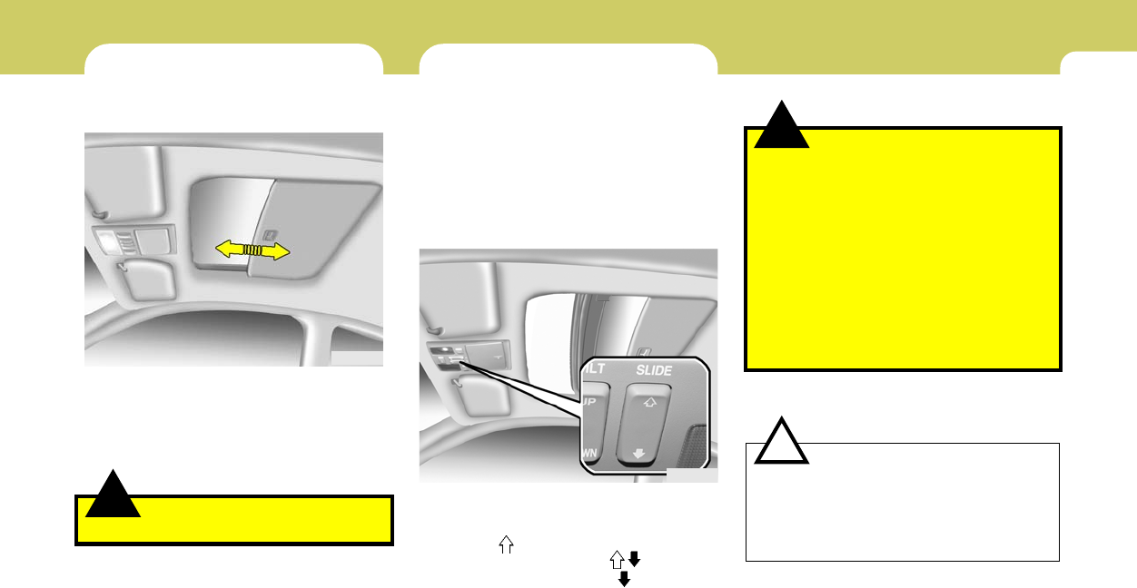
1
FEATURES OF YOUR HYUNDAI
55
!WARNING:
o Do not close a sunroof if anyone’s hands,
arms or body are between the sliding
glass and the sunroof sash, as this could
result in injury.
o Do not place your head or arms out of the
sunroof opening at any time.
o While the vehicle is moving, always keep
the head, hands and other parts of the
body of all occupants away from the roof
opening. Otherwise, you could be seri-
ously injured if the vehicle stops sud-
denly or if the vehicle is involved in an
accident.
CAUTION:
o Do not open the sunroof in severely cold
temperature or when it is covered with
ice or snow.
o Periodically remove any dirt that may
have accumulated on the guide rails.
!
SUNROOF
B460A01S-AAT
(If Installed)
The sunroof can be operated with the ignition
key in the "ON" position.
!
SUNSHADE
B470A01S-AAT
(If Installed)
The sunshade can be opened and closed by
sliding it forward or rearward when the sunroof
is closed. The sunshade will open automatically
when the sunroof is opened, but it must be
closed manually.
HGK2026
WARNING:
Never adjust the sunshade while driving.
B460B03GK-GAT
Opening the Sunroof System
The sunroof can be electrically opened or closed
with the ignition key in the "ON" position. The
sunroof is moved to its fully open position by
pushing the " " switch, and to stop at the desired
position, push in any switches ( , , Up, Down).
To close, press and hold the " " button.
Release the button when the sunroof reaches
the desired position.
HGK2022
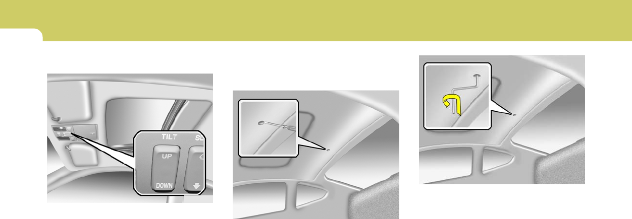
1FEATURES OF YOUR HYUNDAI
56
2. Insert the hexagonal head wrench provided
with the vehicle into the socket. This wrench
can be found in the vehicle’s trunk or glove
box.
3. Push and turn the wrench clockwise to close
or counterclockwise to open the sunroof.
HGK2025
B460C01S-AAT
Tilting the Sunroof System
The sunroof can be tilted by pushing the "UP"
button with the sunroof closed. Release the
button when the sunroof reaches the desired
position. To close the sunroof, press the
"DOWN" button.
NOTE:
After washing the car or after there is rain,
be sure to wipe off any water that is on the
sunroof before operating it.
HGK2023
B460D03GK-AAT
Manual Operation of Sunroof
If the sunroof does not electrically operate:
1. Remove the cap located in the rear roof
panel by using a coin or screw driver.
HGK2024
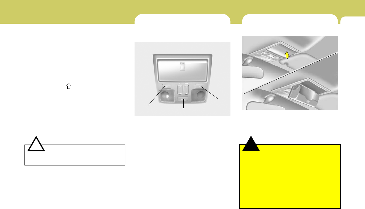
1
FEATURES OF YOUR HYUNDAI
57
HGK2087
B460E03GK-GAT
Resetting the Sunroof System
If the battery has been recharged, discon-
nected or is manually with operating the hex-
agonal head wrench, you may need to reset the
sunroof.
To do this;
1. Turn the ignition switch "OFF".
2. With pressing " " "up" button at the same
time, turn the ignition switch "ON".
The resetting is failed when the ignition
key to the "OFF" within 1.5 seconds.
3. If the sunroof is set like this, the sunroof is
reset with tilting up/down automatically once
for all.
CAUTION:
If the sunroof is not reset, it may not operate
normally.
!
INTERIOR LIGHT
B480A01GK-GAT
MAP LIGHT
(1) Push in the map light switch to turn on the
driver side light.
(2) In the "DOOR" position, the interior cour-
tesy light comes on when any door is
opened regardless of the ignition key posi-
tion. The light goes out gradually 6 seconds
after the door is closed.
(3) Push in the map light switch to turn on the
driver side light.
(1) (2)
(3)
SUNGLASS HOLDER
!
B491A02F-AAT
The sunglass holder is located on the front
overhead console.
Push the end of the cover to open or close the
sunglass holder.
HGK2122
WARNING:
o Do not keep objects except sunglass
inside the sunglass holder. Such ob-
jects can be thrown from the holder in
the event of a sudden stop or an acci-
dent, possibly injuring the passengers
in the vehicle.
o Do not open the sunglass holder while
the vehicle is moving. The rear view
mirror of the vehicle can be blocked by
an open sunglass holder.
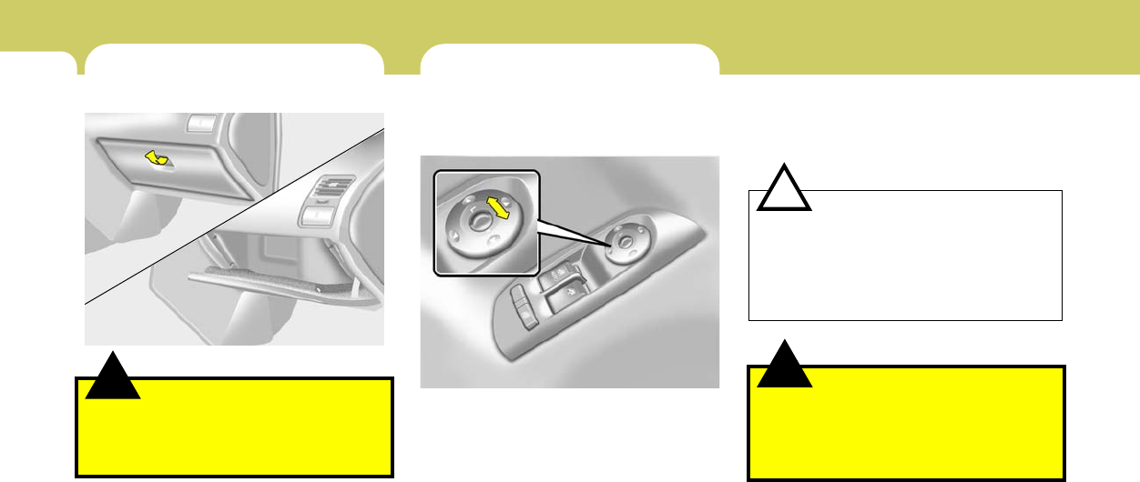
1FEATURES OF YOUR HYUNDAI
58
!
2. Next, adjust the mirror angle by depressing
the appropriate perimeter switch as illus-
trated.
CAUTION:
o Do not operate the switch continuously
for an unnecessary length of time.
o Scraping ice from the mirror face could
cause permanent damage. To remove
any ice, use a sponge, soft cloth or
approved deicer.
WARNING:
Be careful when judging the size or dis-
tance of any object seen in the passenger
side rear view mirror. It is a convex mirror
with a curved surface. Any objects seen in
this mirror are closer than they appear.
!
GLOVE BOX MIRROR
B510B01A-AAT
OUTSIDE REAR VIEW MIRROR
Electric Type
HGK2053
The outside rearview mirrors can be adjusted
to your preferred rear vision, both directly be-
hind the vehicle, and to the rear of the left and
right sides.
The remote control outside rearview mirror
switch controls the adjustments for both the
right and left outside mirror.
To adjust the position of either mirror:
1. Move the selecting switch to the right or left
to activate the adjustable mechanism for the
corresponding door mirror.
!
B500A01A-AAT
WARNING:
To avoid the possibility of injury in case of
an accident or a sudden stop, the glove box
door should be kept closed when the car is
in motion.
HGK2121
o To open the glove box, pull on the glove box
release lever.
1
FEATURES OF YOUR HYUNDAI
59
DAY/NIGHT INSIDE REAR VIEW
MIRROR
B510D01Y-AAT
OUTSIDE REARVIEW MIRROR HEATER
(If Installed)
The outside rearview mirror heater is actuated
in connection with the rear window defroster. To
heat the outside rearview mirror glass, push in
the switch for the rear window defroster. The
rearview mirror glass will be heated for defrost-
ing or defogging and will give you improved rear
vision in inclement weather conditions. Push the
switch again to turn the heater off. The outside
rearview mirror heater automatically turns itself
off after 15 minutes.
HGK2090-1
Type A
Type B
!
B510C01A-AAT
FOLDING THE OUTSIDE REAR VIEW
MIRRORS
To fold the outside rear view mirrors, push them
toward the rear.
The outside rear view mirrors can be folded
rearward for parking in narrow areas.
HGK2055
WARNING:
Do not adjust or fold the outside rear view
mirrors while the vehicle is moving. This
could result in loss of control, and an acci-
dent which could cause death, serious in-
jury or death.
B520A01A-AAT
Your Hyundai is equipped with a day/night inside
rear view mirror. The "night" position is selected
by flipping the tab at the bottom of the mirror
toward you. In the "night" position, the glare of
headlights of cars behind you is reduced.
HGK2052
1FEATURES OF YOUR HYUNDAI
60 PARKING BRAKE
B530A03A-EAT
The parking brake must always be set when the
vehicle is to be left unattended. When the parking
brake is applied, and the ignition key is at the "ON"
position, the parking brake warning lamp will be
illuminated. Before driving the vehicle, the parking
brake must be fully released and the warning lamp
extinguished.
o To engage the parking brake, first apply the
foot brake and then without pressing the
release button in, pull the parking brake lever
up as far as possible.
In addition it is recommended that when
parking the vehicle on a gradient, the shift
lever should be positioned in the appropriate
low gear on manual transmission vehicles or
in the Park position on automatic transmis-
sion vehicles.
HGK3019
B520B02O-GAT
(Electric type) (If installed)
The electric type day/night inside rearview mir-
ror automatically controls the glare of headlights
of the car behind you.
1. Pressing the button turns the auto-
dimming function OFF which is indicated by
the green Status Indicator LED turning off.
2. Pressing the button again turns the auto-
dimming function ON which is indicated by
the green Status Indicator LED turning on.
NOTE:
The mirror defaults to the "ON" position
each time the vehicle is started.
HLZ2068-1
!WARNING:
Whenever leaving vehicle or parking always
set the parking brake as far as possible and
fully engage the vehicle's transaxle into the
park position. Vehicles not fully engaged in
park with the parking brake set are at risk for
moving inadvertently and injuring yourself
or others.
o To release the parking brake, first apply the
foot brake and pull up the parking brake lever
slightly. Secondly, depress the release but-
ton and lower the parking brake lever whilst
holding the button.
1
FEATURES OF YOUR HYUNDAI
61
HIGH-MOUNTED REAR STOP LIGHT
B550A01S-GAT
In addition to the lower-mounted rear stoplights
on either side of the car, the high mounted rear
stoplight in the center of the rear window or
inserted in the rear spoiler also lights when the
brakes are applied.
B550A02GK
Type A Type B Type C
FRONT DOOR EDGE WARNING
LIGHT
B620A01S-AAT
A red light comes on when the front door is
opened. The purpose of this light is to assist
when you get in or out and also to warn passing
vehicles.
B620A01GK
HOOD RELEASE
B570A01GK-GAT
1. Pull the release knob to unlatch the hood.
HGK2019
HGK2020
Hood Release Lever
2. Press the safety hook lever up and lift the
hood.
3. Raise the hood by hand.
1FEATURES OF YOUR HYUNDAI
62
NOTE:
If the fuel-filler lid will not open because ice
has formed around it, tap lightly or push on
the lid to break the ice and release the lid. Do
not pry on the lid. If necessary, spray around
the lid with an approved deicer fluid (do not
use radiator anti-freeze) or move the ve-
hicle to a warm place and allow the ice to
melt.
HGK2018Q
REMOTE FUEL-FILLER LID
RELEASE
B560A03JM-AAT
The fuel-filler lid may be opened from inside the
vehicle by pulling up on the fuel-filler lid opener
located on the front floor area on the left side of
the vehicle.
HGK2017
!
When closing the hood, slowly close the hood
and make sure it locks into place.
WARNING:
o Always double check to be sure that the
hood is firmly latched before driving
away. If it is not latched, the hood could
open while the vehicle is being driven,
causing a total loss of visibility, which
might result in an accident.
o Do not move the vehicle with the hood
in the raised position, as vision is ob-
structed and the hood could fall or be
damaged.
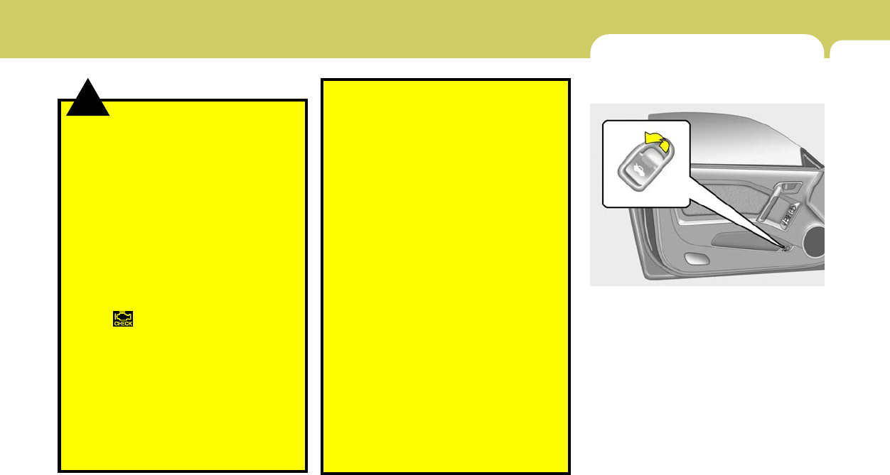
1
FEATURES OF YOUR HYUNDAI
63
WARNING:
o Gasoline vapors are dangerous. Before
refueling, always stop the engine and
never smoke or allow sparks and open
flames near the filler area.
o Never operate your vehicle without a
filler cap properly installed, flammable
vapors and gasoline could leak out in
dangerous situations such as a collision
or rollover. If the filler cap must be
replaced, only use genuine Hyundai re-
placement parts.
o After refueling, make sure the fuel cap is
installed securely to prevent fuel spill-
age in the event of an accident
o Tighten the cap until it clicks, otherwise
the " " light will illuminate
o If you open the fuel filler cap during high
ambient temperatures, a slight "pres-
sure sound" may be heard. This is nor-
mal and not a cause for concern.
Whenever you open the fuel filler cap,
turn it slowly.
o Do not "top off" after the nozzle auto-
matically shuts off when refueling.
o Automotive fuels are flammable/explo-
sive materials. When refueling, please
note the following guidelines carefully.
!- Before touching the fuel nozzle or fuel
filler cap, have one's hands in contact
with metal parts away from the filler
neck to discharge static electricity.
- Do not get back in the vehicle while
refueling. Do not operate anything that
can produce static electricity. Static
electricity discharge can ignite fuel
vapors resulting in an explosion.
- When using a portable fuel container,
be sure to place the container on the
ground while refueling. Static electric-
ity discharge from the container can
ignite fuel vapors causing a fire. While
starting refueling, contact should be
maintained until the filling is complete.
- Do not use cellular phones around a
gas station. The electric current or elec-
tronic interference from cellular phones
can ignite fuel vapors causing a fire.
- When refueling, always turn the engine
off. Sparks by engine compartment
electrical equipment can ignite fuel
vapors causing a fire. After refueling,
check to make sure the fuel filler cap is
securely closed, and then start the
engine.
- Do not smoke or try to light cigarettes
around a gas station. Automotive fuels
are flammable.
TAIL GATE
B540A01F-AAT
Remote Tail Gate Release
To open the tail gate without using the key, pull
up the lid release lever located on the driver's
door panel.
To close, lower the tail gate, then press down on
it until it locks. To be sure the tail gate is securely
fastened, always try to pull it up again.
HGK2012
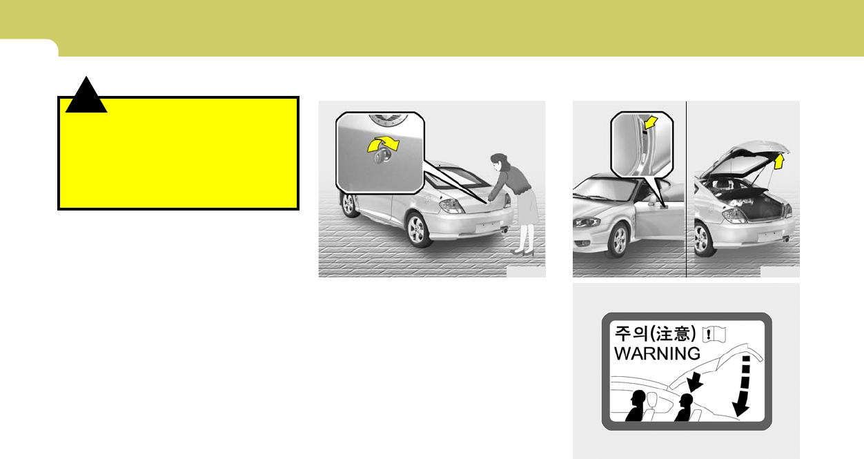
1FEATURES OF YOUR HYUNDAI
64
B540D01GK-GAT
when you close the tailgate
HGK1034
HGK227
B540C01F-AAT
To Unlock Using the Key
To open the tail gate, insert the key and turn it
clockwise to unlock. The tail gate compartment
light illuminates when the tail gate is opened.
HGK2011
!WARNING:
The tail gate should always be kept com-
pletely closed while the vehicle is in motion.
If it is left open or ajar, poisonous exhaust
gases may enter the car resulting in serious
illness or death to the occupants. See addi-
tional warnings concerning exhaust gases
on page 2-2.
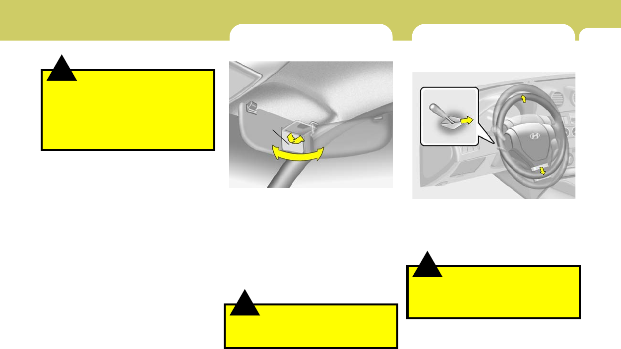
1
FEATURES OF YOUR HYUNDAI
65
!WARNING:
Do not close an open tailgate (rear hatch)
while a person(s) is sitting upright on the
rear seat. The tailgate or tailgate glass may
contact the head of a person sitting upright
on the rear seat. Closing the tailgate onto a
person's head may cause serious injuries,
including death.
!
STEERING WHEEL TILT LEVER
B600A01HP-AAT
(If installed)
To adjust the steering wheel:
1. Pull the lever toward you and hold it to unlock.
2. Raise or lower the steering wheel to the
desired position.
3. After adjustment, release the lever.
WARNING:
Do not attempt to adjust the steering wheel
while driving as this may result in loss of
control of the vehicle and serious injury or
death.
HGK2049
!
B580A02A-AAT
Your Hyundai is equipped with sun visors to give
the driver and front passenger either frontal or
sideward shade. To reduce glare or to shut out
direct rays of the sun, turn the sun visor down.
A vanity mirror is provided on the back of the sun
visor for the front passenger.
NOTE:
The Supplemental Restraint System (SRS)
label containing useful information can be
found on the front of each sun visor.
Vanity mirror
HGK2119
SUN VISOR
WARNING:
Do not place the sun visor in such a manner
that it obscures visibility of the roadway,
traffic or other objects.
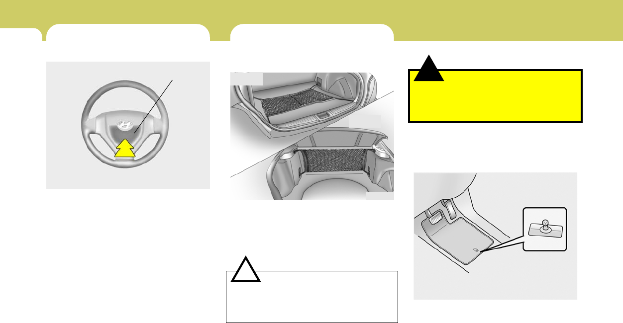
1FEATURES OF YOUR HYUNDAI
66
B990A03Y-AAT
Floor Mat Anchor
When using a floor mat on the front floor carpet,
make sure it attaches to the floor mat anchor in
your vehicle. This keeps the floor mat from
sliding forward.
HGK129
!
LUGGAGE NET
B540D02HP-GAT
(if installed)
Some objects can be kept in the net in the
luggage compartment.
Use the luggage net on the floor(If installed) or
at the back of the luggage compartment to
prevent objects from sliding.
WARNING:
Avoid eye injury. Do not overstretch. Al-
ways keep face and body out of recoil path.
Do not use when strap has visible signs of
wear or damage.
HGK2126
Type B
CAUTION:
To prevent damage to the goods or the
vehicle, care should be taken when carrying
fragile or bulky objects in the luggage com-
partment.
!
Type A
HORN
Working Zone
B610A01S-GAT
Press the pad on the steering wheel to sound the
horn.
HGK2050
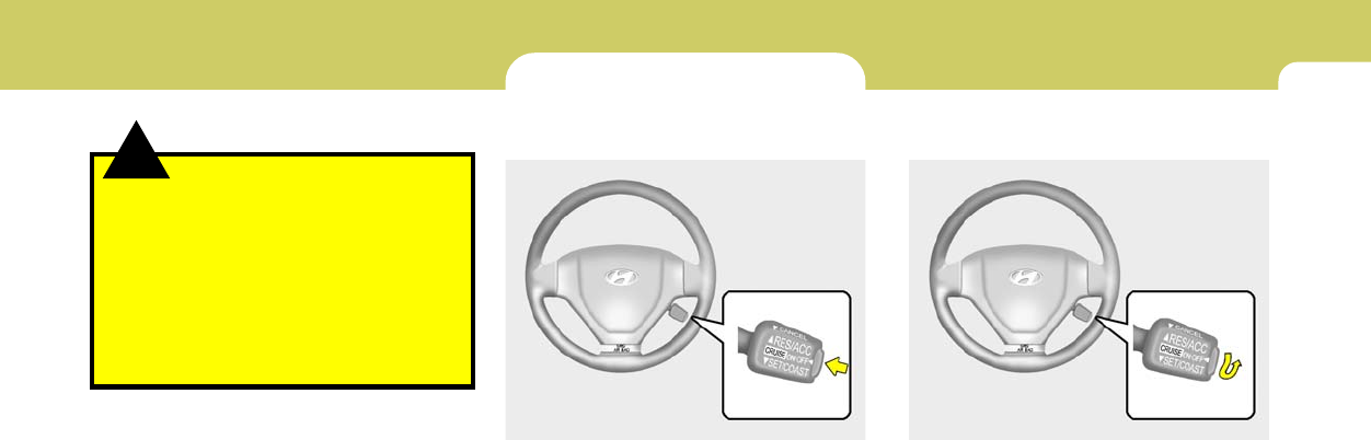
1
FEATURES OF YOUR HYUNDAI
67
!WARNING:
o Make sure the floor mat is properly placed
on the floor carpet. If the floor mat slips
and interferes with the movement of the
pedals during driving, it may cause an
accident.
o Don't put an additional floor mat on the
top of the anchored mat, otherwise the
additional mat may slide forward and
interfere with the movement of the ped-
als.
CRUISE CONTROL
B660A02S-AAT
(If Installed)
The cruise control system provides automatic
speed control for your comfort when driving on
freeways, tollroads, or other noncongested
highways. This system is designed to function
above approximately 25 mph (40 km/h).
NOTE:
Cruise control is not recommended for city
driving, winding roads, slippery roads,
heavy rain, or other bad weather condi-
tions.
B660A01GK
B660B01GK-AAT
To Set the Cruise Speed
1. Push in the cruise control main switch on the
end of the barrel. The "CRUISE" indicator
light in the instrument cluster will be illumi-
nated. This turns the system on.
2. Accelerate to the desired cruising speed
above 25 mph (40 km/h).
3. Push the control switch downward to "SET
(COAST)" and release it.
The "SET" indicator light in the instrument
cluster will illuminate.
4. Remove your foot from the accelerator pedal
and the desired speed will automatically be
maintained.
B660B01GK
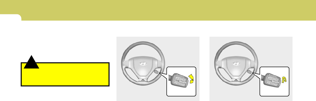
1FEATURES OF YOUR HYUNDAI
68
B660D01E-AAT
To Resume the Preset Speed
The vehicle will automatically resume the speed
set prior to cancellation when you push the
control switch upward to "RESUME (ACCEL)"
position and release it, providing the vehicle
speed is above 25 mph (40 km/h).
B660D01GK
B660C01GK-AAT
To Cancel the Cruise Speed
To disengage the cruise control system, pull the
control switch toward the steering wheel to
"CANCEL" position.
Additionally, the following actions will disengage
the system :
o Depress the brake pedal.
o Depress the clutch pedal (Manual transaxle).
o Shift the selector lever to "N" position (Auto-
matic transaxle).
o Decrease the vehicle speed lower than the
memorized speed by 9 mph (15 km/h).
o Decrease the vehicle speed to less than 25
mph (40 km/h).
o Release the main switch.
B660C01GK
!
5. To momently increase speed, depress the
accelerator pedal enough for the vehicle to
exceed the preset speed. When you remove
your foot from the accelerator pedal, the
vehicle will return to the speed you have set.
WARNING:
To avoid accidental cruise control engage-
ment, keep the cruise control main switch
off when not using the cruise control.
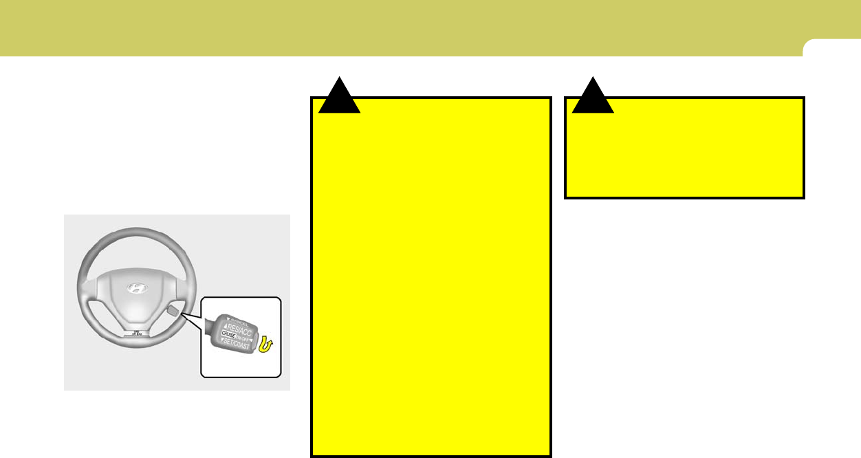
1
FEATURES OF YOUR HYUNDAI
69
B660E01E-AAT
To Reset at a Faster Speed
1. Push the control switch upward to "RE-
SUME (ACCEL)" position and hold it.
2. Accelerate to desired speed and release the
control switch. While the control switch is
held, the vehicle will gradually gain speed.
B660F03E-AAT
To Reset at a Slower Speed
1. Push the control switch downward to "SET
(COAST)" and hold it. The vehicle will decel-
erate.
2. When the desired speed is obtained, release
the control switch. While the control switch
is pushed, the vehicle speed will gradually
decrease.
B660B01GK
!! WARNING:
o Keep the cruise control ON/OFF switch
off when not using the cruise control to
avoid inadvertently setting a speed.
o Use the cruise control system only when
traveling on open highways in good
weather.
o Do not use the cruise control when it
may not be safe to keep the car at a
constant speed, for instance, driving in
heavy or varying traffic, or on slippery
(rainy, icy or snow-covered) or winding
roads or over 6% up-hill or down-hill
roads.
o Pay particular attention to the driving
conditions whenever using the cruise
control system.
o During cruise-control driving with a
manual transaxle vehicle, do not shift
into neutral without depressing the
clutch pedal, or the engine will be
overrevved. If this happens, depress the
clutch pedal or release the main switch.
o With the cruise control engaged, when
the brake pedal is applied, it is normal to
hear the cruise control system deacti-
vate. This is an indication of normal
system operation.
o During normal cruise control operation,
when the "SET(COAST)" is activated or
reactivated after applying the brakes,
the cruise control will energize after
approximately 3 seconds. This delay is
normal.
WARNING:
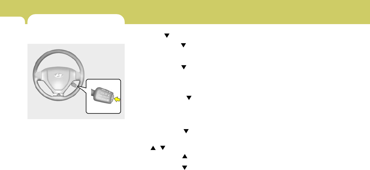
1FEATURES OF YOUR HYUNDAI
70
SEEK (UP / ) Switch
Press the SEEK UP ( ) switch 1 sec. or more.
1. RADIO mode
When the SEEK UP ( ) switch is pressed, the
unit will automatically tune to the next higher
frequency.
2. TAPE mode
Pressing the SEEK UP ( ) switch will play the
beginning of the next music segment.
3. CD (compact disc)/CDC
(compact disc changer) mode
Press the SEEK UP ( ) switch once to skip
forward to the beginning of the next track.
VOL ( / ) Switch
o Press the VOL ( ) button to increase
volume.
o Press the VOL ( ) button to decease
volume.
AUDIO REMOTE CONTROL
SWITCH
B610A01GK-GAT
(If installed)
The steering wheel audio remote control switch
is installed to promote safe driving.
POWER ON/OFF Switch
Press the POWER ON/OFF switch to select
Radio, Tape, CD (compact disc) and CDC
(compact disc changer).
Press the POWER ON/OFF switch once again
to cancel Radio, Tape, CD (compact disc) and
CDC (compact disc changer).
B610A01GK
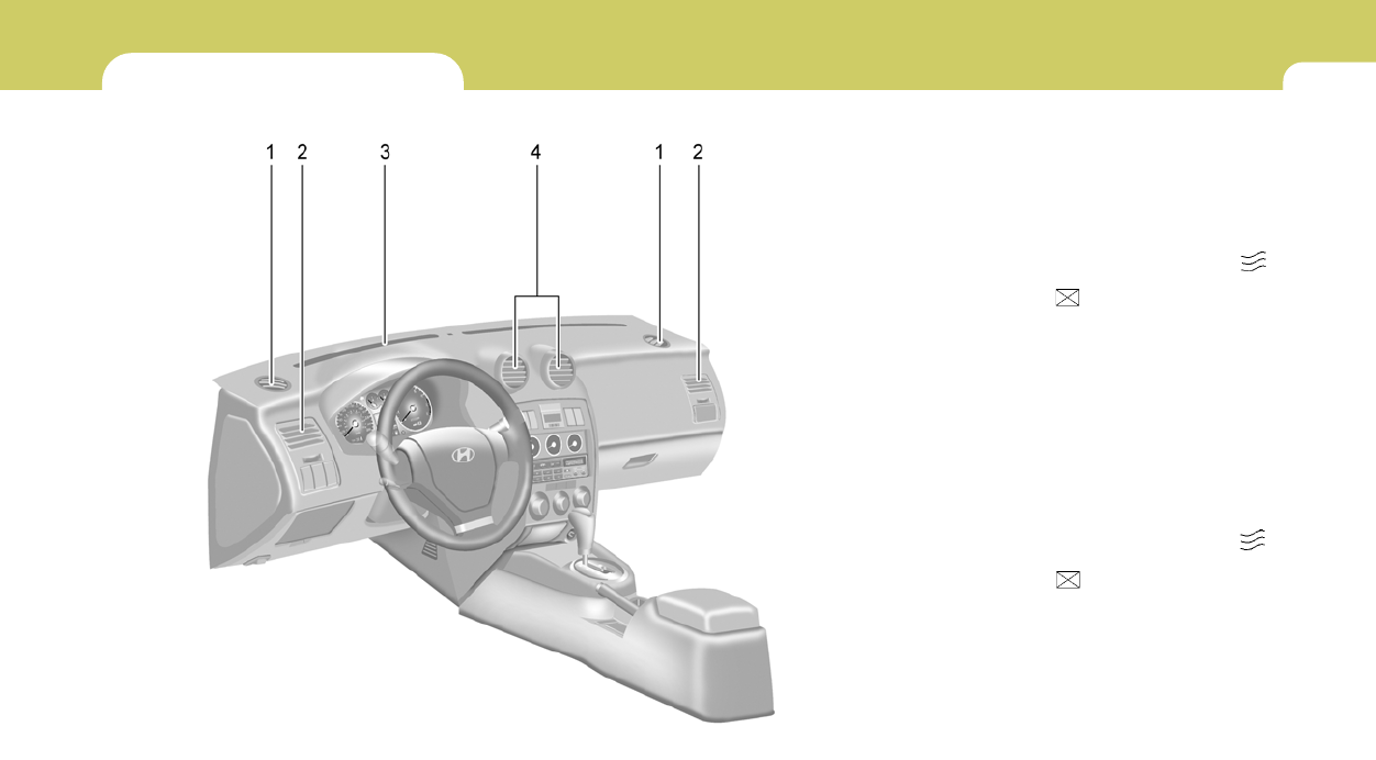
1
FEATURES OF YOUR HYUNDAI
71
HEATING AND COOLING CONTROL
B710A02GK-GAT
1. Side Defrost Nozzle
2. Side Ventilator
3. Windshield Defrost Nozzle
4. Center Ventilator HGK0003-1
B710B02O-AAT
CENTER VENTILATOR
The center ventilators are located in the middle
of the dashboard. To change the direction of the
air flow, move the knob in the center of the vent
up-and-down and side-to-side. The vents are
opened when the vent knob is moved to " "
position. The vents are closed when the vent
knob is moved to " ". Keep these vents clear
of any obstructions.
B710C01JM-AAT
SIDE VENTILATOR
The side ventilators are located on each side of
the dash board. To change the direction of the
air flow, move the knob in the center of the vent
up-and-down and side-to-side. The vents are
opened when the vent knob is moved to " "
position. The vents are closed when the vent
knob is moved to " ". Keep these vents clear
of any obstructions.
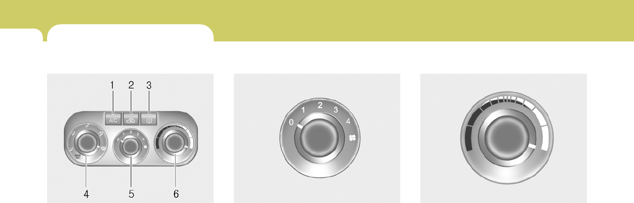
1FEATURES OF YOUR HYUNDAI
72 HEATING AND VENTILATION
B670A01GK-GAT
Rotary Type
1. Air Conditioning switch
2. Air intake control switch
3. Rear window defroster switch
4. Air flow control switch
5. Fan speed control switch
6. Temperature control switch
HGK002-3
B670B02A-AAT
Fan Speed Control (Blower Control)
This is used to turn the blower fan on or off and
to select the fan speed.
This blower fan speed, and therefore the vol-
ume of air delivered from the system, may be
controlled manually by setting the blower con-
trol between the "1" and "4" positions. The "0"
position turns the blower fan off.
NOTE:
If the blower fan is off, the air intake control
is set to the fresh mode automatically.
HGK2093
B670E02A-AAT
Temperature Control
This control is used to adjust the degree of
heating or cooling desired.
Cool
HGK2092
Warm
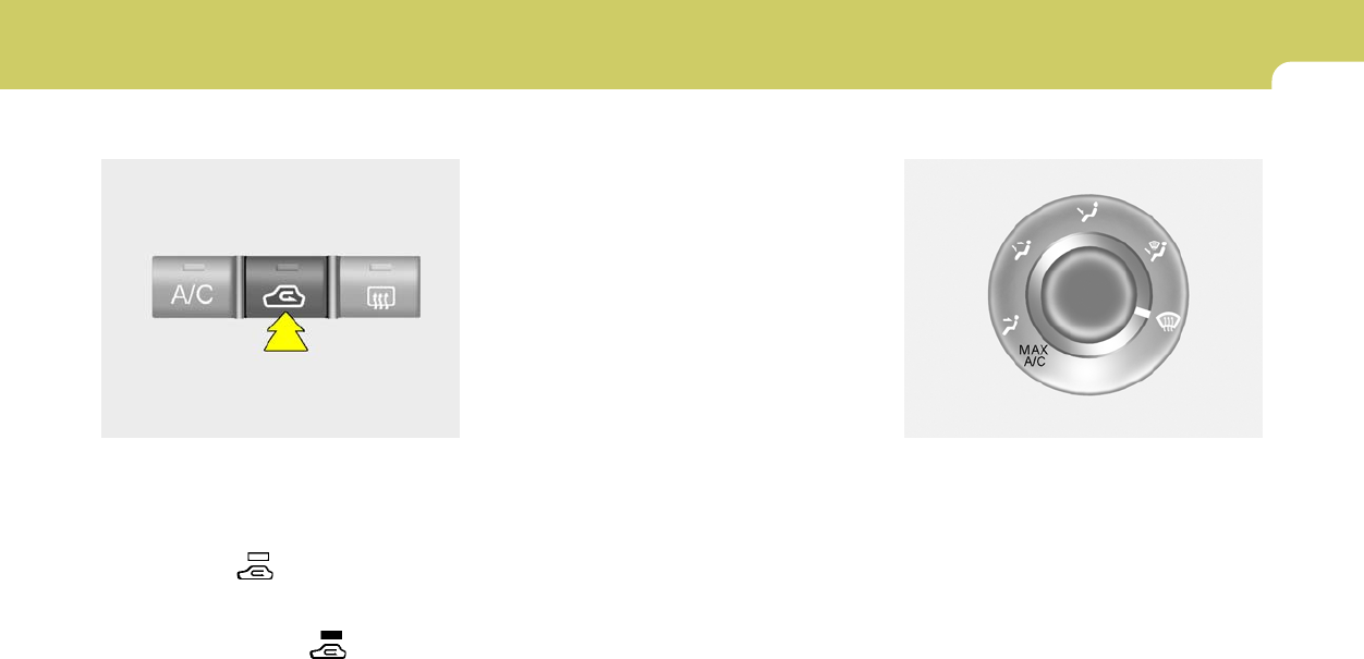
1
FEATURES OF YOUR HYUNDAI
73
B670D04GK-AAT
Air Flow Control
This is used to direct the flow of air. Air can be
directed to the floor, instrument panel outlets, or
windshield. Five symbols are used to represent
Face, Bi-Level, Floor, Floor-Defrost and De-
frost air position. The MAX A/C mode is used to
cool the inside of the vehicle faster.
HGK005-1
B670C02GK-AAT
Air Intake Control
This is used to select fresh outside air or
recirculating inside air.
To change the air intake control mode, (Fresh
mode, Recirculation mode) push the control
button.
FRESH MODE ( ) : The indicator light on
the button goes off when the air intake control
is fresh mode.
RECIRCULATION MODE ( ): The indicator
light on the button is illuminated when the air
intake control is recirculation mode.
With the "Fresh" mode selected, air enters the
vehicle from the outside and is heated or cooled
according to the function selected.
With the "Recirculation" mode selected, air from
within the passenger compartment will be drawn
through the heating system and heated or
cooled according to the function selected.
NOTE:
It should be noted that prolonged opera-
tion of the heating system in "Recircula-
tion" mode will give rise to fogging of the
windshield and side windows and the air
within the passenger compartment will
become stale. In addition, prolonged use of
the air conditioning with the "Recircula-
tion" mode selected may result in the air
within the passenger compartment becom-
ing excessively dry.
HGK2100
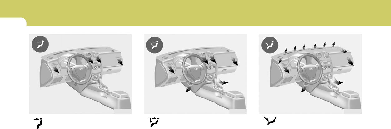
1FEATURES OF YOUR HYUNDAI
74
Face-Level
Selecting the "Face" mode will cause air to be
discharged through the side and center venti-
lators.
Bi-Level
Air is discharged through the dash vents and the
floor vents.
HGK2095 HGK2096
Floor-Level
Air is discharged through the floor vents, wind-
shield defroster nozzle, side defroster nozzle,
side ventilator.
If the "Floor" mode is selected, the "Fresh"
mode will be activated.
HGK2097
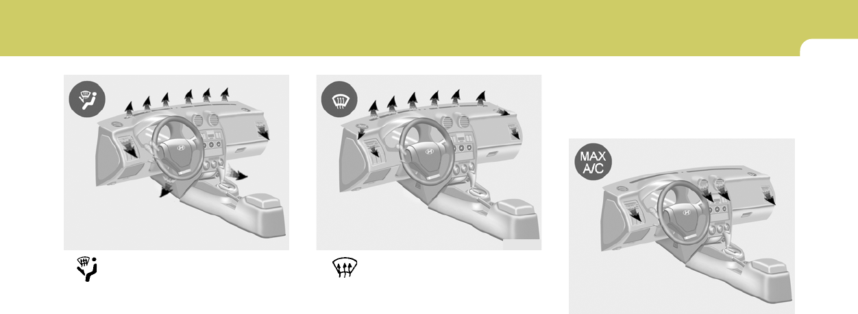
1
FEATURES OF YOUR HYUNDAI
75
MAX A/C-Level
Air is discharged through the face level vents.
If the "MAX A/C" mode is selected, the A/C will
turn on automatically and "Recirculation" mode
will be activated.
HGK021-1
MAX
A/C
mode except the defrost mode and the
floor-defrost mode. Although the A/C
switch indicator is turned off, this is normal
operation.
Defrost-Level
Air is discharged through the windshield defrost
nozzle, side defroster nozzle, side ventilator.
If the "Defrost" mode is selected, the A/C will
turn on automatically and "Fresh" mode will be
activated.
NOTE:
If the "Floor-Defrost" or "Defrost" mode is
selected, the air conditioning will not turn
off by pushing the A/C button.
If the air flow control is set to the defrost or
the floor-defrost mode, the A/C will be on
automatically and the A/C will not off until
the air flow control is set to the another
HGK2099
Floor-Defrost Level
Air is discharged through the windshield defrost
nozzle, the floor vents, side defroster nozzle,
side ventilator.
If the "Floor-Defrost" mode is selected, the A/C
will be turn on automatically and "Fresh" mode
will be activated.
HGK2098
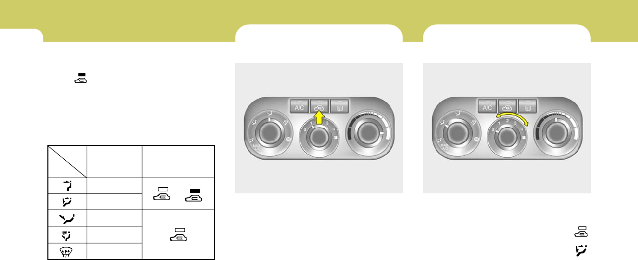
1FEATURES OF YOUR HYUNDAI
76 HEATING CONTROLS
B690A02S-AAT
For normal heating operation, set the air intake
control to the "Fresh" position and the air flow
control to "Floor".
For faster heating, the air intake control should
be in the "Recirculation" position.
If the windows fog up, move the air flow control
to the "Def" (defroster) position. (The A/C will
turn on automatically and "Fresh" mode will be
activated.)
For maximum heat, rotate the temperature
control to the farthest right position.
B690A01GK-A
* The A/C or the air intake control switch return
to its former setting.
A/C
ON
ON or OFF *
ON or OFF *
ON
ON
NOTE:
o The air intake control switch will change
to " " mode when the ignition switch
is turned "ON" with the MAX A/C mode
selected.
o When you change to another mode from
MAX A/C, the A/C and the air intake
control switch are set to the following
chart.
Air Intake
Control Switch
or *
BI-LEVEL HEATING
B700A02E-AAT
Your Hyundai is equipped with bi-level heating
controls. To use this feature:
o Set the air intake control to the fresh air ( )
position.
o Set the air flow control at the bi-level ( )
position.
o Adjust the fan speed control to the desired
speed.
o Set the temperature control between "Cool"
and "Warm".
B700A01GK-A
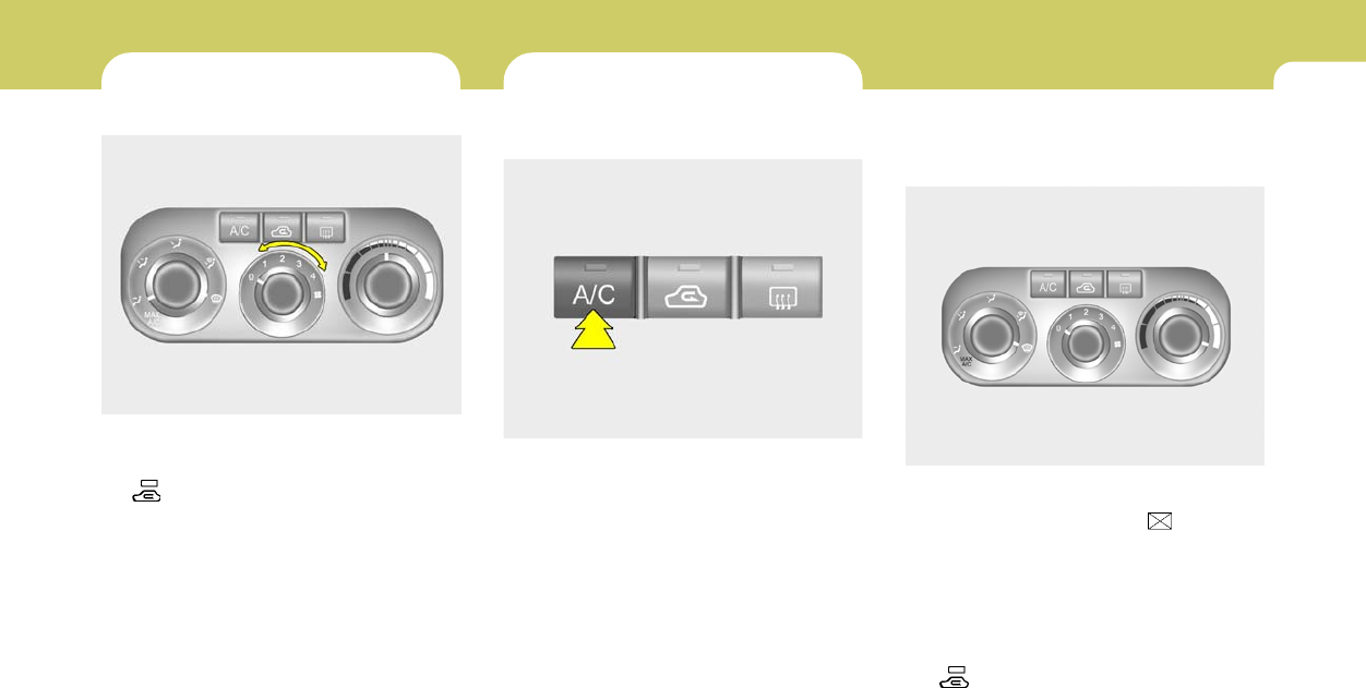
1
FEATURES OF YOUR HYUNDAI
77
To use the air conditioning to cool the interior:
o Set the side vent control to " ", to shut off
outside air entry.
o Turn on the fan control switch.
o Turn on the air conditioning switch by push-
ing in on the switch. The air conditioning
indicator light should come on at the same
time.
o Set the air intake control to "Fresh" mode
( ).
B710A01GK-A
VENTILATION
B710A01S-AAT
To operate the ventilation system:
o Set the air intake control to "Fresh" mode
( ).
o To direct all intake air to the instrument panel
vents, set the airflow control to "Face".
o Adjust the fan speed control to the desired
speed.
o Set the temperature control between "Cool"
and "Warm".
AIR CONDITIONING SYSTEM
B740A01S-AAT
Air Conditioning Switch (If installed)
The air conditioning is turned on or off by
pushing the A/C button on the heating/air con-
ditioning control panel.
HGK2089-1
B740B01S-AAT
Air Conditioning Operation
Cooling
HGK002-1
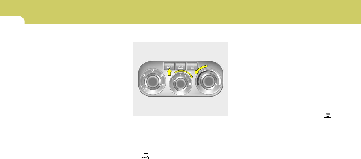
1FEATURES OF YOUR HYUNDAI
78
o Set the temperature control to "Cool". ("Cool"
provides maximum cooling. The tempera-
ture may be moderated by moving the con-
trol toward "Warm".)
o Adjust the fan control to the desired speed.
For greater cooling, turn the fan control to
one of the higher speeds or temporarily
select the "Recirculation" position on the air
intake control.
B740C01S-AAT
Dehumidified Heating
B730A01FC-AAT
Operation Tips
o To keep dust or unpleasant fumes from
entering the car through the ventilation sys-
tem, temporarily set the air intake control to
"Recirculation". Be sure to return the control
to "Fresh" when the irritation has passed to
keep fresh air in the vehicle. This will help
keep the driver alert and comfortable.
o Air for the heating/cooling system is drawn
in through the grilles just ahead of the wind-
shield. Care should be taken that these are
not blocked by leaves, snow, ice or other
obstructions.
o To prevent interior fog on the windshield, set
the air intake control to the fresh air ( )
position and fan speed to the desired posi-
tion.
For dehumidified heating:
o Turn on the fan control switch.
o Turn on the air conditioning switch. The air
conditioning indicator light should come on at
the same time.
o Set the air intake control to "Fresh" mode
( ).
o Set the air flow control to "Face".
o Adjust the fan control to the desired speed.
o For more rapid action, set the fan at one of
the higher speeds.
o Adjust the temperature control to provide the
desired amount of warmth.
B740C01GK-A
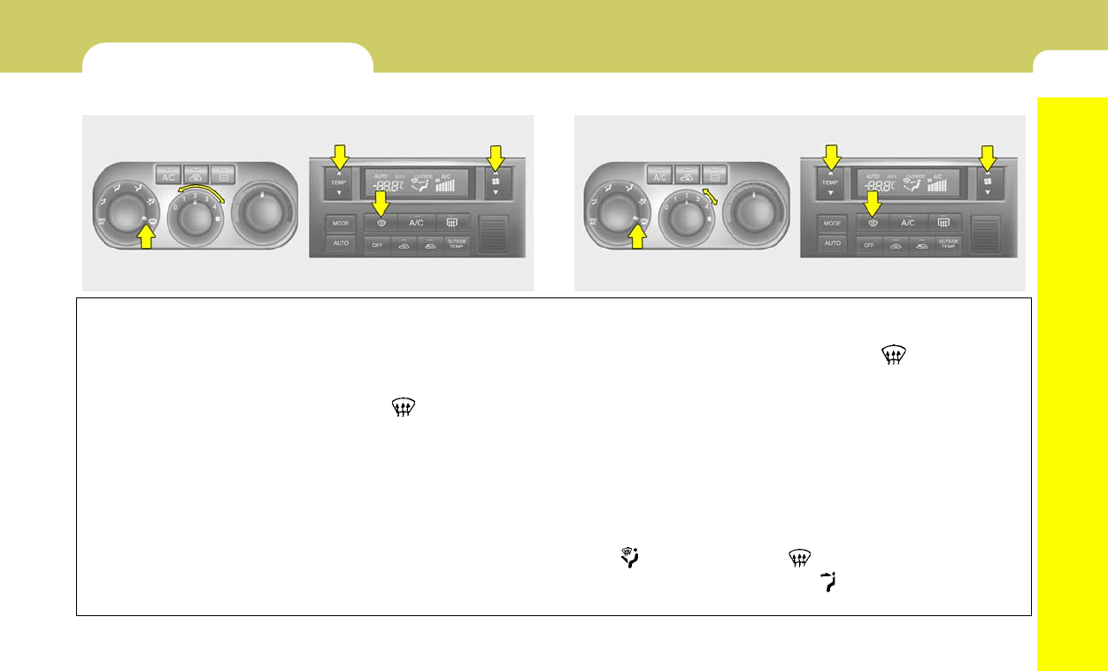
1
FEATURES OF YOUR HYUNDAI
79
DEFROSTING/DEFOGGING
B720A02FC-GAT
Use the heating/ventilation system to defrost or defog the
windshield:
To remove interior fog on the windshield:
o Set the air flow control to the defrost ( ) position. (The
A/C will turn on automatically and "Fresh" mode will be
activated)
o Set the temperature control to the desired position.
o Set the fan speed control between "1" and "4" position.
To remove frost or exterior fog on the windshield:
o Set the air flow control to the defrost ( ) position. (The
A/C will turn on automatically and "Fresh" mode will be
activated.)
o Set the temperature control to warm.
o Set the fan speed control to position "3" or "4".
NOTE:
When the A/C is operated continuously on the floor-defrost level ( ) or defrost level ( ), it may cause fog to form
on the exterior windshield. If this occurs, set the air flow control to the face level position ( ) and fan speed control
to the low position.
A Type
B720A01GK-1 B720A02GK-1
B Type A Type B Type
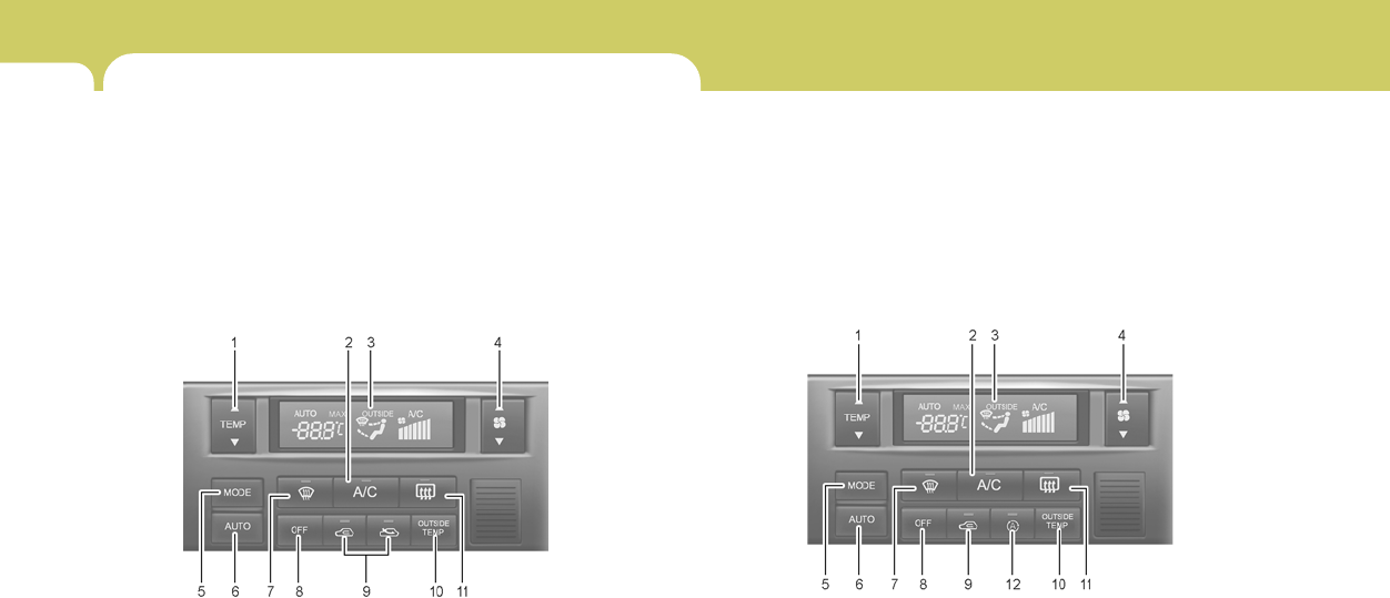
1FEATURES OF YOUR HYUNDAI
80 AUTOMATIC HEATING AND COOLING CONTROL SYSTEM
B970A01Y-AAT
(If lnstalled)
Your Hyundai is equipped with an automatic heating and cooling control system controlled by simply setting the desired temperature.
B970B02GK-GAT
Heating and Cooling Controls
TYPE A (Without Air Quality System) TYPE B (With Air Quality System)
1. Temperature Control Button
2. Air Conditioning Switch
3. Display Window
4. Fan Speed Control Switch
5. Air Flow Control Switch
6. AUTO (Automatic Control) Switch
7. Defroster Switch
8. OFF Switch
9. Air lntake Control Switch
10.Ambient Temperature Switch
11.Rear Window Defroster Switch
12.Air Quality System Switch (If installed)
HGK2101 HGK2102
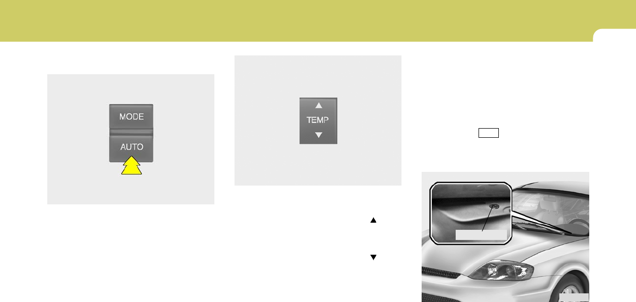
1
FEATURES OF YOUR HYUNDAI
81
B970C02E-AAT
Automatic Operation
The FATC (Full Automatic Temperature Con-
trol) system automatically controls heating and
cooling as follows:
1. Push the "AUTO" switch. The indicator light
will illuminate confirming that the Face, Floor
and/or Bi-Level modes as well as the blower
speed and, air conditioner will be controlled
automatically.
HGK2106 2. Push the "TEMP" button to set the desired
temperature.
The temperature will increase to the maxi-
mum 90°F(32°C) by pushing on the button.
Each push of the button will cause the tem-
perature to increase by 1°F(0.5°C).
The temperature will decrease to the mini-
mum 62°F(17°C) by pushing on the button.
Each push of the button will cause the tem-
perature to decrease by 1°F(0.5°C).
NOTE:
If the battery has been discharged or dis-
connected, the temperature mode will reset
to centigrade degrees.
This is a normal condition and you can
change the temperature mode from centi-
grade to farenheit as follows;
Press the TEMP button down 3 seconds or
more with the button held down. The
display shows that the unit of temperature
is adjusted to centigrade or fahrenheit.
(°C →→
→→
→ °F or °F →→
→→
→ °C)
NOTE:
Never place anything over the sensor which
is located on the instrument panel to en-
sure better control of the heating and cool-
ing system.
HGK2103
HGK2076
Photo sensor
OUTSIDE
TEMP
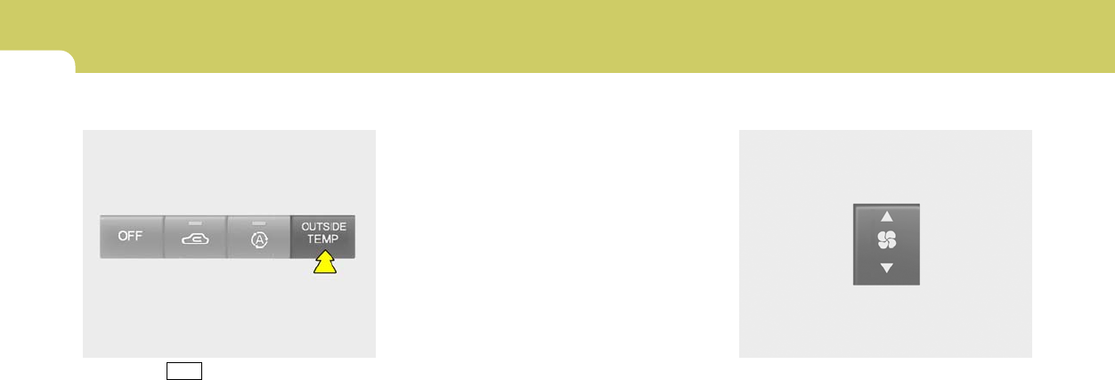
1FEATURES OF YOUR HYUNDAI
82
B995A01Y-GAT
Ambient Temperature Switch
Pressing the button displays the ambient
temperature on the display.
HGK2109
B980A01Y-AAT
MANUAL OPERATION
The heating and cooling system can be con-
trolled manually as well by pushing buttons
other than the "AUTO" button. In this state, the
system sequentially works according to the
order of buttons selected.
The function of the buttons which are not se-
lected will be controlled automatically.
Press the "AUTO" button in order to convert to
automatic control of the system.
B980B01Y-AAT
Fan Speed Control Switch
The fan speed can be set to the desired speed
by pressing the appropriate fan speed control
button. The higher the fan speed is, the more air
is delivered. Pressing the "OFF" button turns off
the fan.
HGK2104
OUTSIDE
TEMP
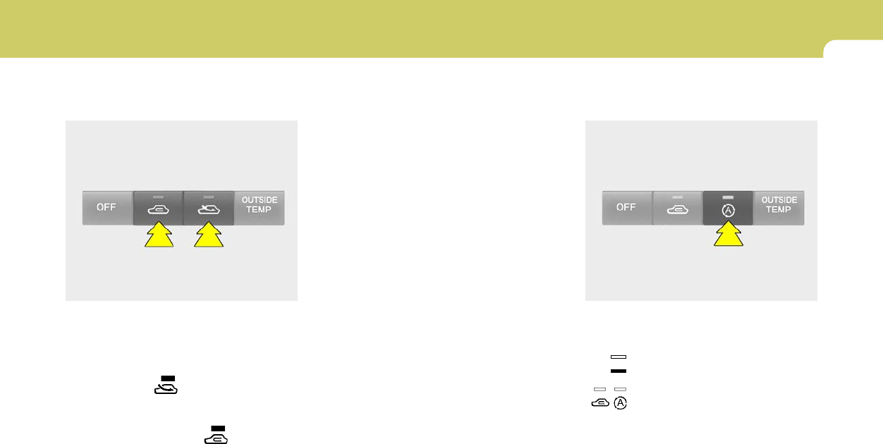
1
FEATURES OF YOUR HYUNDAI
83
HGK2110-1
B670C02GK-AAT
Air Intake Control Switch
(Without A.Q.S)
This is used to select fresh outside air or
recirculation inside air.
To change the air intake control mode, (Fresh
mode, Recirculation mode) push the control
button.
FRESH MODE ( ) : The indicator light on
the button goes on when the air intake control
is in fresh mode.
RECIRCULATION MODE ( ) : The indica-
tor light on the button is illuminated when the air
intake control is in recirculation mode.
With the "Fresh" mode selected, air enters the
vehicle from the outside and is heated or cooled
according to the function selected.
With the "Recirculation" mode selected, air from
within the passenger compartment will be drawn
through the heating system and heated or
cooled according to the function selected.
NOTE:
It should be noted that prolonged opera-
tion of the heating system in "recirculation"
mode will give rise to fogging of the wind-
shield and side windows and the air within
the passenger compartment will become
stale. In addition, prolonged use of the air
conditioning with the "Recirculation" mode
selected may result in the air within the
passenger compartment becoming exces-
sively dry.
B980C02GK-GAT
Air Intake Control Switch (With A.Q.S)
(If Installed)
This is used to select fresh outside air or
recirculate inside air automatically.
: OFF
: ON
Fresh mode :
Air enters the vehicle from the outside and is
heated or cooled according to the function
selected.
HGK2110
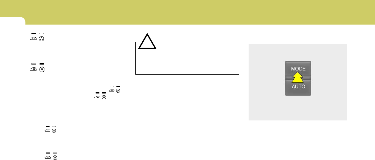
1FEATURES OF YOUR HYUNDAI
84
Recirculation mode :
Air from within the passenger compartment will
be drawn through the heating system and heated
or cooled according to the function selected.
Exhaust gas cutoff mode :
Air enters the vehicle from the outside.
But if exhaust gas enters the vehicle from the
outside, the exhaust gas cutoff mode ( ) is
automatically converted to the mode, to
prevent exhaust gas from entering the vehicle.
NOTE:
It should be noted that prolonged opera-
tion of the heating system in recirculation
mode ( ) will give rise to misting of the
windshield and side windows and the air
within the passenger compartment will
become stale. In addition, prolonged use of
the air conditioning with the recirculation
mode ( ) selected may result in the air
within the passenger compartment becom-
ing excessively dry.
!
B980E01GK-GAT
Air Flow Control
B980D01Y-AAT
Heating and Cooling System Off
Press the "OFF" button to stop the operation of
the heating and cooling system.
This is used to direct the flow of air. Air can be
directed to the floor, instrument panel outlets, or
windshield. Four symbols are used to represent
Face, Bi-Level, Floor and Floor-Defrost air
position.
HGK2105
CAUTION:
If the windows fog up with the Recircula-
tion or A.Q.S mode selected, set the air
intake control to the Fresh air position or
A.Q.S control to "OFF".
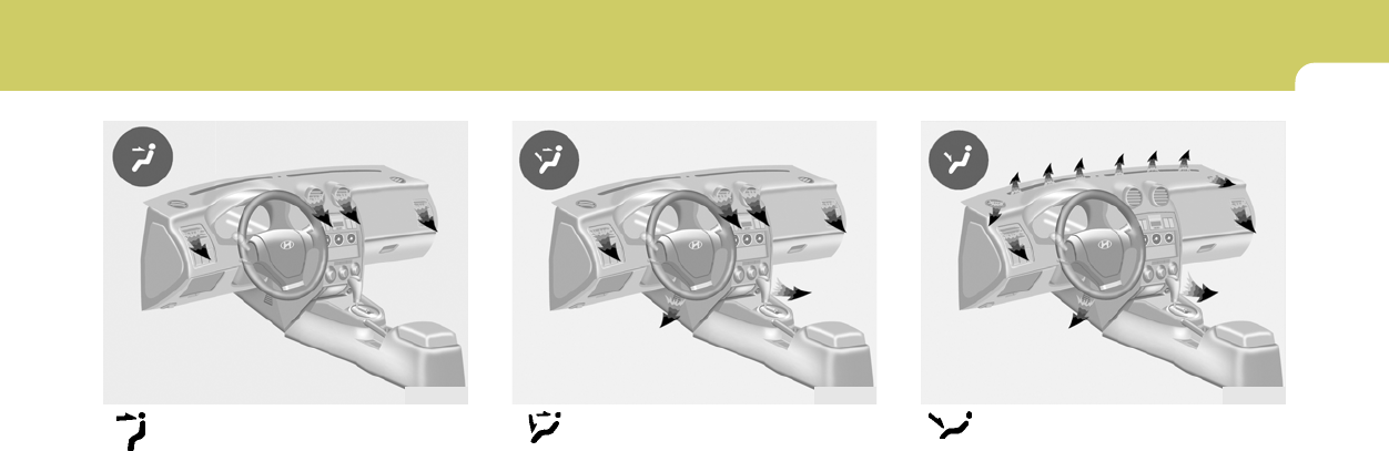
1
FEATURES OF YOUR HYUNDAI
85
Face-Level
When selecting the "Face" mode, the indicator
light will come on, causing air to be discharged
through the face level vents.
HGK2095
Bi-Level
When selecting the "Bi-Level" mode, the indica-
tor light will come on and the air will be dis-
charged through the face vents and the floor
vents. This makes it possible to have cooler air
from the dashboard vents and warmer air from
the floor outlets at the same time.
HGK2096
Floor-Level
When selecting the "Floor-Level" mode, the
indicator light will come on and the air will be
discharged through the floor vents, windshield
defroster nozzle, side defroster nozzle, side
ventilator.
HGK2097
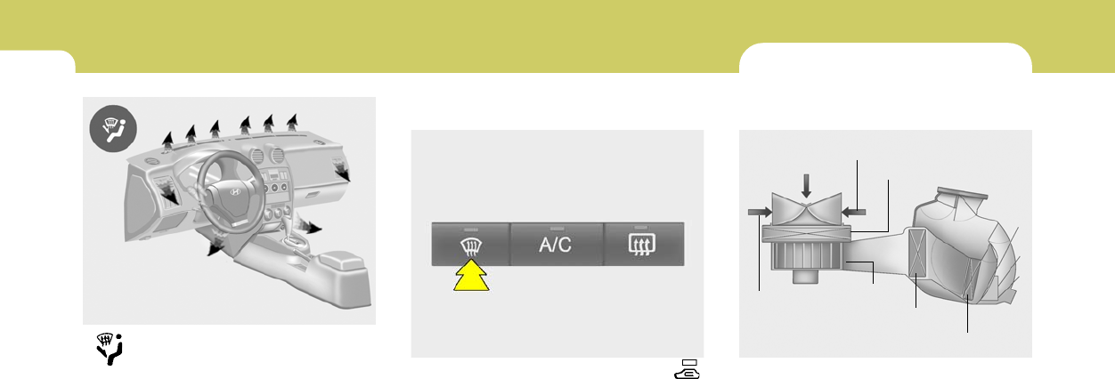
1FEATURES OF YOUR HYUNDAI
86
Floor-Defrost Level
When selecting the "Floor-Defrost" mode, the
indicator light will come on and the air will be
discharged through the windshield defrost
nozzle, the floor vents, side defroster nozzle,
side ventilator.
HGK2098
B980F02E-AAT
Defrost Switch
When the "Defrost" button is pressed, the " "
mode will be automatically selected and the air
will be discharged through the windshield de-
frost vents. To assist in defrosting, the air
conditioning will operate if ambient temperature
is higher than 38.3 °F (3.5 °C) and automatically
turns off if the ambient temperature drops below
38.3 °F (3.5 °C).
HGK012
CLIMATE CONTROL AIR FILTER
(IN FRONT OF BLOWER UNIT)
B760A06GK-AAT
(If Installed)
The climate control air filter is located in front of
the blower uniit behind the glove box.
It operates to decrease the amount of pollutants
entering the car.
To replace the climate control air filter, refer to
the page 6-18.
B760A01E
Evaporator core
Filter
Heater core
Outside air
Inside air
Inside air
Blower fan

1
FEATURES OF YOUR HYUNDAI
87
!CAUTION:
o Replace the filter every 10,000 miles
(15,000 km) or once a year. If the car is
being driven in severe conditions such
as dusty, rough roads, more frequent
climate control air filter inspections and
changes are required.
o When the air flow rate is decreased, the
system should be checked at an autho-
rized dealer.
o If your vehicle is not equipped with this
filter, it can be installed by your dealer.
Check with your dealer for details.
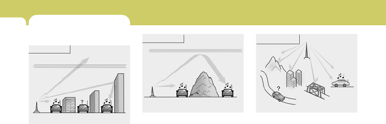
1FEATURES OF YOUR HYUNDAI
88 STEREO SOUND SYSTEM
Ionosphere
B750A02L
AM reception
Mountains
Buildings
Unobstructed
area
FM radio station
B750A03L
FM reception
B750A01L
Obstructed area Iron bridges
FM broadcasts are transmitted at high frequen-
cies and do not bend to follow the earth's
surface. Because of this, FM broadcasts gen-
erally begin to fade at short distances from the
station. Also, FM signals are easily affected by
buildings, mountains, or other obstructions.
These can result in certain listening conditions
which might lead you to believe a problem exists
with your radio. The following conditions are
normal and do not indicate radio trouble:
AM broadcasts can be received at greater
distances than FM broadcasts. This is because
AM radio waves are transmitted at low frequen-
cies. These long, low frequency radio waves
can follow the curvature of the earth rather than
travelling straight out into the atmosphere. In
addition, they curve around obstructions so that
they can provide better signal coverage.
B750A02A-AAT
How Car Audio Works
AM and FM radio signals are broadcast from
transmitter towers located around your city.
They are intercepted by the radio antenna on
your car. This signal is then received by the
radio and sent to your car speakers.
When a strong radio signal has reached your
vehicle, the precise engineering of your audio
system ensures the best possible quality repro-
duction. However, in some cases the signal
coming to your vehicle may not be strong and
clear. This can be due to factors such as the
distance from the radio station, closeness of
other strong radio stations or the presence of
buildings, bridges or other large obstructions in
the area.
Ionosphere
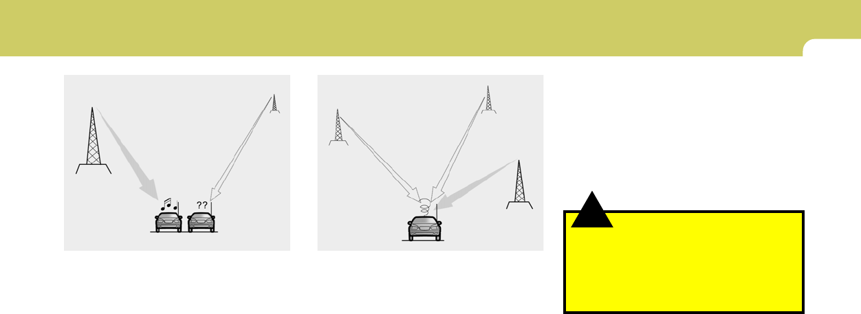
1
FEATURES OF YOUR HYUNDAI
89
B750A04L B750A05L
o Station Swapping - As an FM signal weak-
ens, another more powerful signal near the
same frequency may begin to play. This is
because your radio is designed to lock onto
the clearest signal. If this occurs, select
another station with a stronger signal.
o Multi-Path Cancellation - Radio signals being
received from several directions can cause
distortion or fluttering. This can be caused by
a direct and reflected signal from the same
station, or by signals from two stations with
close frequencies. If this occurs, select
another station until the condition has passed.
o Fading - As your car moves away from the
radio station, the signal will weaken and
sound will begin to fade. When this occurs,
we suggest that you select another stronger
station.
o Flutter/Static - Weak FM signals or large
obstructions between the transmitter and
your radio can disturb the signal causing
static or fluttering noises to occur. Reducing
the treble level may lessen this effect until the
disturbance clears.
!
B750B05Y-AAT
Using a cellular phone or a two-way radio
When a cellular phone is used inside the vehicle,
noise may be produced from the audio equip-
ment. This does not mean that something is
wrong with the audio equipment. In such a case,
use the cellular phone at a place as far as
possible from the audio equipment.
WARNING:
Hyundai recommends that you never use a
cell phone while driving. This could result
in loss of control, and an accident that may
cause death, serious injury, or property
damage. You must stop at a safe place to
use a cellular phone.
NOTE:
Some states and cities have regulations
prohibiting the use of cell phones while
driving. You should be aware of the specific
requirements in your area.
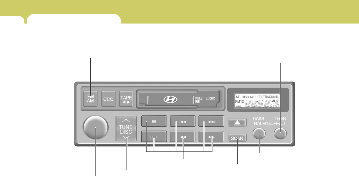
1FEATURES OF YOUR HYUNDAI
90 AUDIO SYSTEM
H240A01O-GAT
STEREO RADIO OPERATION (H250) (If Installed)
1. POWER ON/OFF, VOLUME Control Knob
H250A01GK
2. BASS/BALANCE Control Knob
(BASS/BAL)
3. TREBLE/FADER Control Knob
(TREB/FAD)
4. TUNE/SEEK Select Button
5. BAND Selector
6. PRESET Buttons
7. SCAN Button

1
FEATURES OF YOUR HYUNDAI
91
H240B02A-GAT
1. POWER ON-OFF Control
Knob
The radio unit may be operated when the ignition
key is in the "ACC" or "ON" position. Press the
knob to switch the power on. The LCD shows
the radio frequency in the radio mode or the tape
direction indicator in the tape mode. To switch
the power off, press the knob again.
VOLUME Control
Rotate the knob clockwise to increase the
volume and turn the knob counterclockwise to
reduce the volume.
2. BASS Control Knob
Press to pop the knob out and turn to the left or
right for the desired bass tone.
BAL (Balance Control) Knob
Pull the bass control knob further out. Turn the
control knob clockwise to emphasize right
speaker sound (left speaker sound will be
attenuated).
When the control knob is turned counterclock-
wise, left speaker sound will be emphasized
(right speaker sound will be attenuated).
3. TREB (Treble Control) Knob
Press to pop the knob out and turn to the left or
right for the desired treble tone.
FAD (Fader Control) Knob
Pull the treble control knob further out.
Turn the control knob counterclockwise to
emphasize front speaker sound (rear speaker
sound will be attenuated).
When the control knob is turned clockwise, rear
speaker sound will be emphasized (front
speaker sound will be attenuated).
4. TUNE (Manual) Select Button
Press the side or side to increase or to
decrease the frequency. Press either button
and hold down to continuously scroll. Release
button once the desired station is reached.
SEEK Operation
(Automatic Channel Selection)
Press the TUNE select button 1 sec or
more.Releasing it will automatically tune to the
next available station with a beep sound.
When the side is pressed longer than 1 second,
releasing will automatically tune to the next
higher frequency and when the side is pressed
longer than 1 second, releasing will automati-
cally tune to the next lower frequency.
5. BAND Selector
Pressing the button changes the AM,
FM1 and FM2 bands. The mode selected is
displayed on LCD.
6. PRESET STATION SELECT
Button
Six (6) stations for AM, FM1 and FM2 respec-
tively can be preset in the electronic memory
circuit on this unit.
HOW TO PRESET STATIONS
Six AM and twelve FM stations may be pro-
grammed into the memory of the radio. Then, by
simply pressing the band select button and/or
one of the six station select buttons, you may
recall any of these stations instantly. To pro-
gram the stations, follow these steps:
o Press band selector to set the band for AM,
FM1, or FM2.
o Select the desired station to be stored by
seek or manual tuning.
o Determine the preset station select button
you wish to use to access that station.
FM/AM

1FEATURES OF YOUR HYUNDAI
92
!
o Press the station select button for more than
two seconds. A select button indicator will
show in the display indicating which select
button you have depressed. The frequency
display will flash after it has been stored into
the memory with a beep sound. You should
then release the button, and proceed to
program the next desired station. A total of
18 stations can be programmed by selecting
one AM and two FM stations per button.
o When completed, any preset station may be
recalled by selecting AM, FM1 or FM2 band
and the appropriate station button.
7. SCAN Button
When the scan button is pressed, the frequency
will increase and the receivable stations will be
tuned in one after another, receiving each sta-
tion for 5 seconds. To stop scanning, press the
scan button again.
CAUTION:
o Do not place beverages close to the
audio system. The audio system mecha-
nism may be damaged if you spill them.
o Do not impact on the audio system, or
the audio system mechanism could be
damaged.
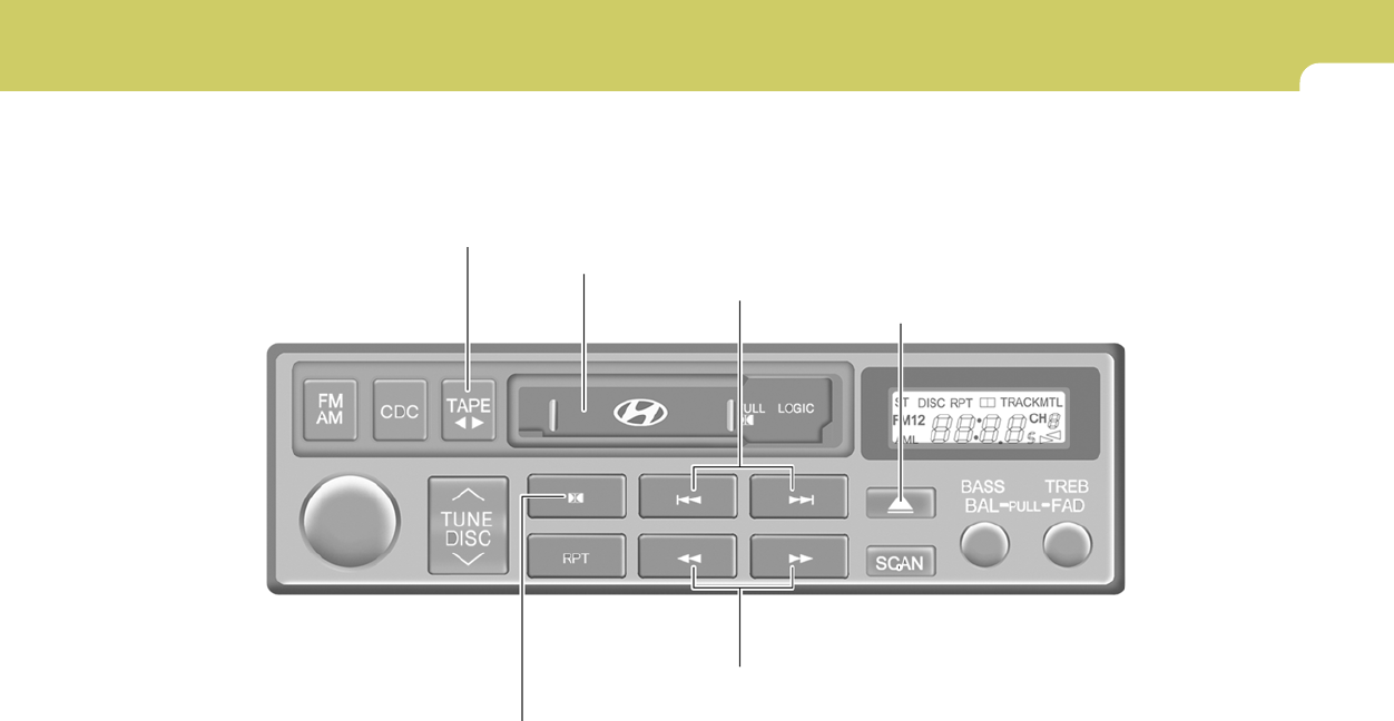
1
FEATURES OF YOUR HYUNDAI
93
H240C01O-GAT
CASSETTE TAPE PLAYER OPERATION (H250) (If Installed)
1. FF/REW Button
H240C01GK
2. AUTO MUSIC SELECT Button
3. TAPE PROGRAM Button
4. EJECT Button
5. DOLBY SELECT Button
6. TAPE SLOT

1FEATURES OF YOUR HYUNDAI
94
!
H240A02O-AAT
1. FF/REW Button
o The FF (fast forward tape winding) starts
when the button is pressed during PLAY
or REW.
o The PLAY starts when the button is
pressed again during FF.
o The REW (rewinding) starts when the
button is pressed during PLAY or FF.
o The PLAY starts when the button is
pressed again during REW.
2. AUTO MUSIC SELECT Button
Press the button to find the starting point of each
song in a prerecorded music tape.
The quiet space between songs (must have at
least a 4 sec. gap) can be identified by the AUTO
MUSIC SELECT button.
o Pressing the button will play the beginning
of the next music segment.
o Pressing the button will start replay at
the beginning of the music just listened to.
3. TAPE PROGRAM Button
This allows you to play the reverse side of the
tape by merely depressing the program button.
An arrow will appear in the display to show tape
direction.
NOTE:
When tape operation is abnormal or ER8
fault code is displayed, press the eject
button more than 5 seconds to reset the
deck function.
4. EJECT Button
o When the EJECT button is pressed with a
cassette loaded, the cassette will eject.
o When the EJECT button is pressed during
FF/REW, the cassette will eject.
5. DOLBY SELECT Button
If you get background noise during PLAY, you
can reduce this considerably by merely press-
ing DOLBY SELECT button.
If you want to release, press the button again.
CAUTION:
o Do not insert anything like coins into the
player slot as damage to the unit may
occur.
o Do not place beverages close to the
audio system. The playback mechanism
may be damaged if you spill them.
o Do not impact on the audio system, or
the playback mechanism could be dam-
aged.
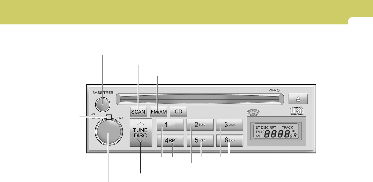
1
FEATURES OF YOUR HYUNDAI
95
H260A01O-AAT
STEREO RADIO OPERATION (H260) (If installed)
H260A01GK
1. POWER ON-OFF/VOLUME/BALANCE Control Knob
2. FADER Control Knob
3. BASS/TREBLE Control Knob
4. SCAN Button
7. PRESET Buttons
5. TUNE/SEEK Select Button
6. BAND Selector

1FEATURES OF YOUR HYUNDAI
96
H260B03E-AAT
1. POWER ON-OFF Control Knob
The radio unit may be operated when the ignition
key is in the "ACC" or "ON" position. Press the
knob to switch the power on. The LCD shows
the radio frequency in the radio mode or the CD
track indicator in either the CD mode or CD
AUTO CHANGER mode. To switch the power
off, press the knob again.
VOLUME Control
Rotate the knob clockwise to increase the
volume and turn the knob counterclockwise to
reduce the volume.
BALANCE Control
Pull and turn the control knob clockwise to
emphasize right speaker sound (left speaker
sound will be attenuated). When the control
knob is turned counterclockwise, left speaker
sound will be emphasized (right speaker sound
will be attenuated).
2. FAD (Fader Control) Knob
Turn the control knob counterclockwise to
emphasize front speaker sound (rear speaker
sound will be attenuated). When the control
knob is turned clockwise, rear speaker sound
will be emphasized (front speaker sound will be
attenuated).
3. BASS Control Knob
Press to pop the knob out and turn to the left or
right for the desired bass tone.
TREB (Treble Control) Knob
Pull the bass control knob further out. Turn to the
left or right for the desired treble tone.
4. SCAN Button
When the scan button is pressed, the frequency
will increase and the receivable stations will be
tuned in one after another, receiving each sta-
tion for 5 seconds. To stop scanning, press the
scan button again.
5. TUNE (Manual) Select Button
Press the ( ) side or ( ) side to increase or to
decrease the frequency. Press either button
and hold down to continuously scroll. Release
button once the desired station is reached.
SEEK Operation (Automatic Channel
Selection)
Press the TUNE select button for 1 sec or more.
Releasing it will automatically tune to the next
available station with a beep sound.
When the ( ) side is pressed longer than 1
second, releasing will automatically tune to the
next higher frequency and when the ( ) side
is pressed longer than 1 second, releasing will
automatically tune to the next lower frequency.

1
FEATURES OF YOUR HYUNDAI
97
6. BAND Selector
Pressing the button changes the AM,
FM1 and FM2 bands. The mode selected is
displayed on LCD.
7. PRESET STATION SELECT
Button
Six (6) stations for AM, FM1 or FM2 respec-
tively can be preset in the electronic memory
circuit on this unit.
HOW TO PRESET STATIONS
Six AM and twelve FM stations may be pro-
grammed into the memory of the radio. Then, by
simply pressing the band select button and/or
one of the six station select buttons, you may
recall any of these stations instantly. To pro-
gram the stations, follow these steps:
o Press band selector to set the band for AM,
FM1 or FM2.
o Select the desired station to be stored by
seek, scan or manual tuning.
o Determine the preset station select button
you wish to use to access that station.
o Press the station select button for more than
two seconds. A select button indicator will
show in the display indicating which select
button you have depressed. The frequency
display will flash after it has been stored into
the memory.
You should then release the button, and
proceed to program the next desired station.
A total of 18 stations can be programmed by
selecting one AM and two FM stations per
button.
o When completed, any preset station may be
recalled by selecting AM, FM1 or FM2 band
and the appropriate station button.
CAUTION:
o Do not place beverages close to the
audio system. The audio system mecha-
nism may be damaged if you spill them.
o Do not impact on the audio system, or
the audio system mechanism could be
damaged.
!
FM/AM
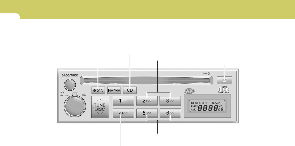
1FEATURES OF YOUR HYUNDAI
98
H260B01O-AAT
COMPACT DISC PLAYER OPERATION (H260) (If installed)
H260B01GK
1. Playing CD
2. FF/REW Button
3. TRACK UP/DOWN
4. SCAN Button
5. REPEAT Button
6. EJECT Button

1
FEATURES OF YOUR HYUNDAI
99
B260D03O-AAT
1. Playing CD
o Insert the CD with the label facing upward.
o Insert the CD to start CD playback, during
radio operation.
o When a disc is in the CD deck, if you press
the CD button, the CD player will begin
playing even if the radio is being used.
o The CD player can be used when the ignition
switch is in either the "ON" or "ACC" position.
2. FF/REW ( / )
If you want to fast forward or reverse through
the compact disc track, push and hold the FF
( ) or REW ( ) button.
When you release the button, the compact disc
player will resume playing.
3. TRACK UP/DOWN
o The desired track on the disc currently being
played can be selected using the track
number.
o Press once to skip forward to the beginn-
ing of the next track. Press once to skip
back to the beginning of the track.
4. SCAN Button
o Press the SCAN button to playback the first
10 seconds of each track.
o Press the SCAN button again within 10 sec.
When you have reached the desired track.
5. REPEAT Button
o To repeat the track you are currently listen-
ing to, press the RPT button. To cancel ,
press again.
o If you do not release RPT operation when the
track ends, it will automatically be replayed.
This process will be continued until you push
the button again.
6. EJECT Button
When the EJECT button is pressed with a
CD loaded, the CD will eject.
NOTE:
o If the CD does not operate properly or if
the ER2 fault code is displayed, use one
of two methods to reset the CD deck
function.
- Remove the audio fuse for 5 minutes.
Then, reinstall the audio fuse.
- Disconnect the negative terminal of
the battery and wait 5 minutes. Then
reconnect the negative battery termi-
nal.
o To assure proper operation of the unit,
keep the vehicle interior temperature
within a normal range by using the
vehicle’s air conditioning or heating
system.
o When replacing the fuse, replace it with
a fuse having the correct capacity.
o The preset station frequencies are all
erased when the car battery is discon-
nected. Therefore, all data will have to be
set again if this should occur.
o Do not add any oil to the rotating parts.
Keep magnets, screwdrivers and other
metallic objects away from the tape
mechanism and head.
o This equipment is designed to be used
only in a 12 volt DC battery system with
negative ground.

1FEATURES OF YOUR HYUNDAI
100
o This unit is made of precision parts. Do
not attempt to disassemble or adjust
any parts.
o When driving your vehicle, be sure to
keep the volume of the unit set low
enough to allow you to hear sounds
coming from the outside.
o Do not expose this equipment (includ-
ing the speakers) to water or excessive
moisture.
!CAUTION:
o Do not insert warped or poor quality
discs into the CD player as damage to the
unit may occur.
o Do not insert anything like coins into the
player slot as damage to the unit may
occur.
o Do not place beverages close to the
audio system. The playback mechanism
may be damaged if you spill them.
o Do not impact on the audio system, or
the playback mechanism could be dam-
aged.
o Driving off-road or other vibrations may
skip your compact disc.
Do not use the audio system off-road as
the discs could be scratched and dam-
aged.
o Do not grip or pull out the disc with your
hand while the disc is being pulled into
the unit by the self loading mechanism.
These can cause poor disc scratching to
occur or trouble in the compact disc
player.
o Avoid using CD-Recordable or CD-
Rewritable to ensure proper operation.
When using the compact disc player,
genuine CDs are recommended.
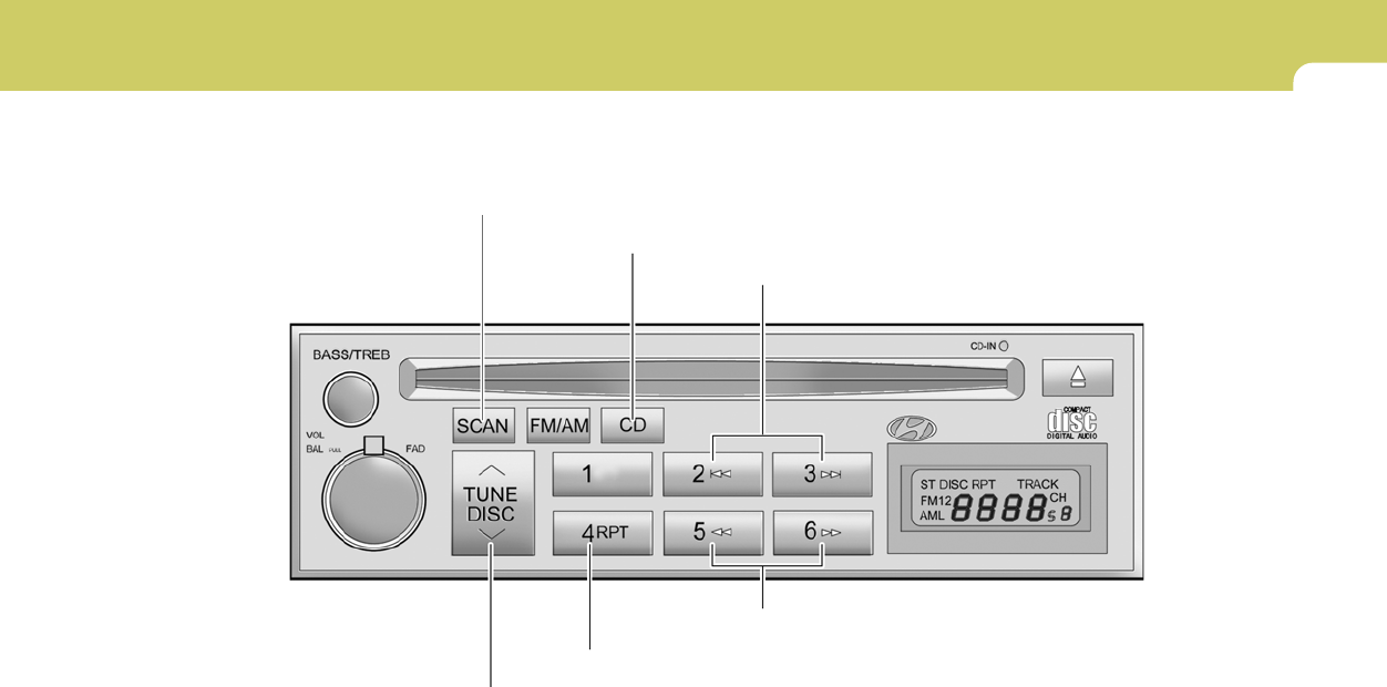
1
FEATURES OF YOUR HYUNDAI
101
B260E01E-AAT
CD AUTO CHANGER (H260) (If installed)
H260E01GK
1. CD Select Button
2. DISC Select Button
3. TRACK UP/DOWN
4. FF/REW Button
5. REPEAT Button
6. SCAN Button

1FEATURES OF YOUR HYUNDAI
102
B260F01GK-AAT
The CD auto changer is located in the right side
of the quater trim.
o To use the CD auto changer.
1. Open the sliding lid of the CD auto changer.
2. To eject the compact disc magazine, press
the EJECT button located inside the CD auto
changer.
3. Insert the discs into the magazine.
4. Push the magazine into the CD auto changer
and close the sliding lid.
o The CD auto changer can be used when the
ignition switch is in either the "ON" or "ACC"
position.
1. CD Select Button
When the CD changer magazine contains discs,
press the "CD" button and the CD changer can
be used even if the radio is being used. The
Hyundai CD changer can hold up to eight discs.
The disc number will be lit, and the track number,
and elapsed time will be displayed.
2. DISC Select Button
To select the CD you want, push " " to change
the disc number.
3. TRACK UP/DOWN
o The desired track on the disc currently being
played can be selected using the track
number.
o Press once to skip forward to the begin-
ning of the next track. Press once to skip
back to the beginning of the track.
4. FF/REW ( / )
If you want to fast forward or reverse through
the compact disc track, push and hold in the FF
( ) or REW ( ) button.
When you release the button, the compact disc
player will resume playing.
5. REPEAT
o To repeat the music you are listening to,
press the RPT button. To cancel, press
again.
o If you do not release RPT operation when the
track ends, it will automatically be replayed.
This process will be continued until you push
the button again.
6. SCAN Button
o Press the SCAN button to playback the first
10 seconds of each track.
o Press the SCAN button again within 10 sec.
for the desired track.
NOTE:
o When replacing the fuse, replace it with
a fuse having the correct capacity.
o This equipment is designed to be used
only in a 12 volt DC battery system with
negative ground.
o This unit is made of precision parts. Do
not attempt to disassemble or adjust
any parts.
o When driving your vehicle, be sure to
keep the volume of the unit set low
enough to allow you to hear sounds
coming from the outside.
TUNE
DISC

1
FEATURES OF YOUR HYUNDAI
103
CAUTION:
o Do not insert warped or poor quality
discs into the CD changer as damage to
the unit may occur.
o Do not insert anything like coins into the
changer slot as damage to the unit may
occur.
o Do not place beverages close to the
audio system. The playback mechanism
may be damaged if you spill them.
o Do not impact on the audio system, or
the playback mechanism could be dam-
aged.
o Driving off-road or other vibrations may
skip your compact disc.
Do not use the audio system off-road as
the discs could be scratched and dam-
aged.
o Do not grip or pull out the disc with your
hand while the disc is being pulled into
the unit by the self loading mechanism.
These can cause disc scratching to oc-
cur or trouble in the compact disc
changer.
o Avoid using CD-Recordable or CD-
Rewritable to ensure proper operation.
When using the compact disc changer,
genuine CDs are recommended.
!
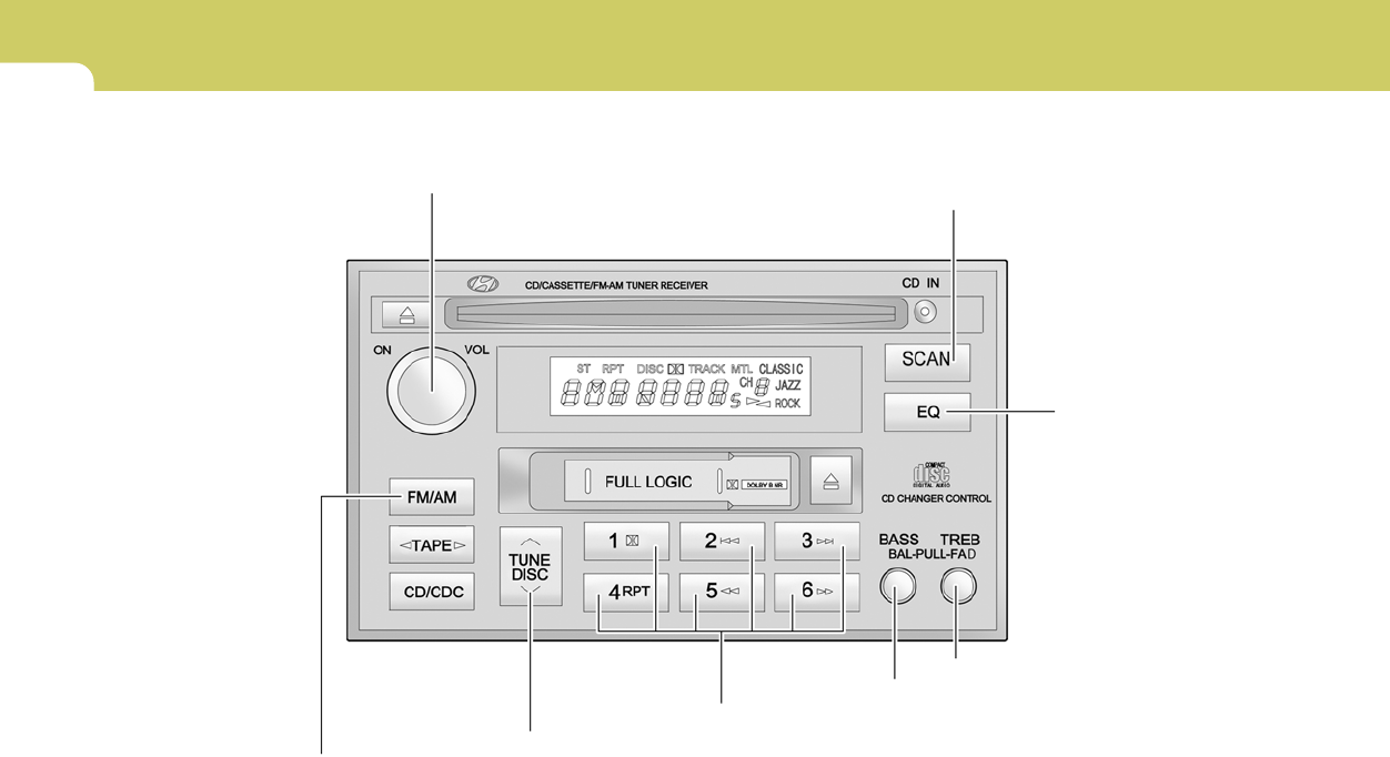
1FEATURES OF YOUR HYUNDAI
104
H290A01FC-GAT
STEREO RADIO OPERATION (H280) (If installed)
H290A01GK
1. POWER ON/OFF VOLUME Control Knob
2. BASS/BALANCE Control Knob
3. TREBLE/FAD Konb
4. TUNE/SEEK Select Button
5. PRESET Buttons
6. BAND Select Button
7. EQUALIZER Button
8. SCAN Button (If installed)

1
FEATURES OF YOUR HYUNDAI
105
H290B03E-GAT
1. POWER ON-OFF Control Knob
The radio unit may be operated when the ignition
key is in the "ACC" or "ON" position. Press the
button to switch the power on. The display
shows the radio frequency in the radio mode,
the tape direction indicator in the tape mode or
CD track in either the CD mode or CD AUTO
CHANGER mode. To switch the power off,
press the button again.
VOLUME Control
Rotate the knob clockwise to increase the
volume and turn the knob counterclockwise to
reduce the volume.
2. BASS/BALANCE Control Knob
BASS Control Knob
Press to pop the knob out. To increase the bass,
rotate the knob clockwise, while to decrease the
bass, rotate the knob counterclockwise.
BALANCE Control knob
Pull the Bass control knob out further. Rotate the
knob clockwise to emphasize right speaker
sound (left speaker sound will be attenuated).
When the control knob is turned counterclock-
wise, left speaker sound will be emphasized
(right speaker sound will be attenuated).
3. TREBLE/FAD Knob
TREBLE Control Knob
Press to pop the knob out and turn to the left or
right for the desired treble tone.
FAD (Fader Control) Knob
Pull the Treble control knob out further. Turn the
control knob counterclockwise to emphasize
front speaker sound (rear speaker sound will be
attenuated). When the control knob is turned
clockwise, rear speaker sound will be empha-
sized (front speaker sound will be attenuated).
4. TUNE (Manual) Select Button
Press the ( ) side or ( ) side to increase or to
decrease the frequency. Press either button
and hold down to continuously scroll. Release
button once the desired station is reached.
SEEK Operation (Automatic Channel
Selection)
Press the TUNE select button for 0.5 sec or
more. Releasing it will automatically tune to the
next available station with a beep sound.
When the ( ) side is pressed longer than 0.5
second, releasing will automatically tune to the
next higher frequency and when the ( ) side is
pressed longer than 0.5 second, releasing will
automatically tune to the next lower frequency.
5. PRESET STATION Select Buttons
Six (6) stations for AM, FM and FM2 respec-
tively can be preset in the electronic memory
circuit.
HOW TO PRESET STATIONS
Six AM and twelve FM stations may be pro-
grammed into the memory of the radio. Then, by
simply pressing the band select button and/or
one of the six station select buttons, you may
recall any of these stations instantly. To pro-
gram the stations, follow these steps:

1FEATURES OF YOUR HYUNDAI
106
o Press band selector to set the band for AM,
FM or FM2.
o Select the desired station to be stored by
seek or manual tuning.
o Determine the preset station select button
you wish to use to access that station.
o Press the station select button for more than
two seconds. A select button indicator will
show in the display indicating which select
button you have depressed. The frequency
display will flash after it has been stored into
the memory with beep sound. You should
then release the button, and proceed to
program the next desired station. A total of
18 stations can be programmed by selecting
one AM and two FM station per button.
o When completed, any preset station may be
recalled by selecting AM, FM or FM2 band
and the appropriate station button.
6. BAND Selector
Pressing the button changes the AM,
FM1 and FM2 bands. The mode selected is
shown on the display.
7. EQUALIZER Button
Press the EQ button to select the CLASSIC,
JAZZ, ROCK and DEFEAT MODE for the
desired tone quality. Each press of the button
changes the display as follows;
CLASSIC → JAZZ → ROCK → DEFEAT
FM/AM
8. SCAN Button (If installed)
When the scan button is pressed, the frequency
will increase and the receivable stations will be
tuned in one after another, receiving each sta-
tion for 5 seconds. To stop scanning, press the
scan button again.
!CAUTION:
o Do not place beverages close to the
audio system. The audio system mecha-
nism may be damaged if you spill them.
o Do not impact on the audio system, or
the audio system mechanism could be
damaged.
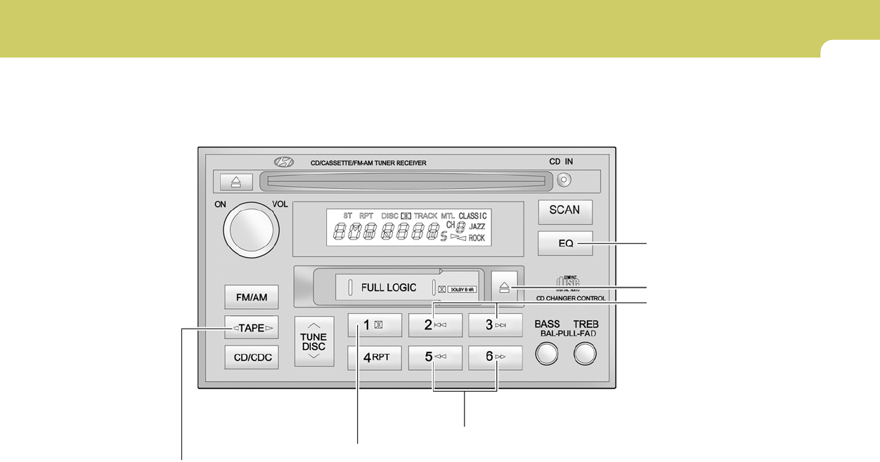
1
FEATURES OF YOUR HYUNDAI
107
H290C01FC-GAT
CASSETTE TAPE PLAYER OPERATION (H280) (If installed)
H290A02GK
1. FF/REW Button
2. AUTO MUSIC Select Button
5. EQUALIZER Button
3. TAPE PROGRAM Button
4. TAPE EJECT Button
6. DOLBY Button
1FEATURES OF YOUR HYUNDAI
108
H290D02O-GAT
1. FF/REW Button
o Fast forward tape winding starts when the
FF ( ) button is pressed during the PLAY
or REW mode.
o Tape play starts when the FF ( ) button
is pressed again during the FF mode.
o Tape rewinding starts when the REW
( ) button is pressed during the PLAY or
FF mode.
o Tape play starts when the REW ( ) button
pressed again during the REW mode.
2. AUTO MUSIC Select Button
Press the button to find the starting point of each
song in a prerecorded music tape. The quiet
space between songs (must have at least a 4
sec. gap) can be identified by the AUTO MUSIC
Select button.
o Pressing the button will play the beginn-
ing of the next music segment.
o Pressing the button will start replay at
the beginning of the music just listened to.
3. TAPE PROGRAM Button
This allows you to play the reverse side of the
tape by merely depressing the program button.
An arrow will appear in the display to show tape
direction.
4. TAPE EJECT button
o When the button is pressed with the
cassette loaded, the cassette is ejected.
o When the button is pressed during the
FF/REW mode, the cassette is ejected.
5. EQ Button
Press the EQ button to select the CLASSIC,
JAZZ, ROCK and DEFEAT MODE for the
desired tone quality. Each press of the button
changes the display as follows;
CLASSIC → JAZZ → ROCK → DEFEAT
6. DOLBY Button
If you get background noise during tape PLAY,
you can reduce this considerably by merely
pressing the DOLBY button. If you want to
cancel the DOLBY feature, press the button
again.
!CAUTION:
o Do not insert anything like coins into the
player slot as damage to the unit may
occur.
o Do not place beverages close to the
audio system. The playback mechanism
may be damaged if you spill them.
o Do not impact on the audio system, or
the playback mechanism could be dam-
aged.
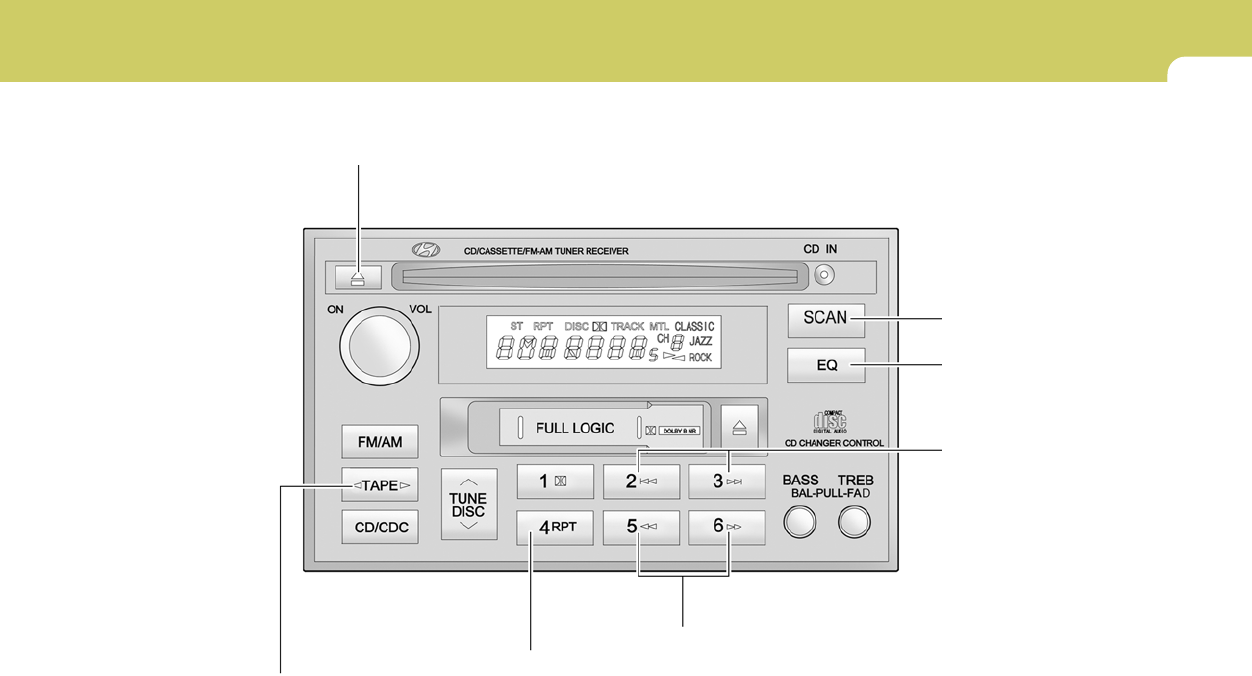
1
FEATURES OF YOUR HYUNDAI
109
H290E01FC-GAT
COMPACT DISC PLAYER OPERATION (H280) (If installed)
H290A03GK
1. CD Select Button
2. FF/REW Button
5. EQUALIZER Button
3. TRACK UP/DOWN
4. REPEAT
7. SCAN Button (If installed)
6. CD EJECT Button

1FEATURES OF YOUR HYUNDAI
110
H290F01O-GAT
1. CD Select Button
o Insert the CD with the label facing upward.
o Insert the CD to start CD playback, during
radio operation or cassette tape playing.
o When a disc is in the CD deck, if you press
the CD button the CD player will begin playing
even if the radio or cassette player is being
used.
o The CD player can be used when the ignition
switch is in either the "ON" or "ACC" position.
2. FF/REW ( / )
If you want to fast forward or reverse through
the compact disc track, push and hold the FF
( ) or REW ( ) button.
When you release the button, the compact disc
player will resume playing.
3. TRACK UP/DOWN
o The desired track on the disc currently being
played can be selected using the track
number.
o Press button once to skip forward to the
beginning of the next track. Press button
once to skip back to the beginning of the
track.
4. REPEAT
o To repeat the track you are listening to,
press the RPT button. To cancel, press
again.
o If you do not release RPT operation when the
track ends, it will automatically be replayed.
This process will be continued until you push
the button again.
5. EQUALIZER Button
Press the EQ button to select the CLASSIC,
JAZZ, ROCK and DEFEAT MODE for the
desired tone quality. Each press of the button
changes the display as follows;
7. SCAN Button (If installed)
o Press the SCAN button to playback the first
10 seconds of each track.
o Press the SCAN button again within 10 sec.
When you have reached the desired track.
NOTE:
o To assure proper operation of the unit,
keep the vehicle interior temperature
within a normal range by using the
vehicle’s air conditioning or heating
system.
o When replacing the fuse, replace it with
a fuse having the correct capacity.
o The preset station frequencies are all
erased when the car battery is discon-
nected. Therefore, all data will have to be
set again if this should occur.
o Do not add any oil to the rotating parts.
Keep magnets, screwdrivers and other
metallic objects away from the tape
mechanism and head.
o This equipment is designed to be used
only in a 12 volt DC battery system with
negative ground.
o This unit is made of precision parts. Do
not attempt to disassemble or adjust
any parts.
CLASSIC → JAZZ → ROCK → DEFEAT
6. CD EJECT Button
When the button is pressed with a CD loaded,
the CD will eject.

1
FEATURES OF YOUR HYUNDAI
111
o When driving your vehicle, be sure to
keep the volume of the unit set low
enough to allow you to hear sounds
coming from the outside.
o Do not expose this equipment (includ-
ing the speakers and tape) to water or
excessive moisture.
!CAUTION:
o Do not insert warped or poor quality
discs into the CD player as damage to the
unit may occur.
o Do not insert anything like coins into the
player slot as damage to the unit may
occur.
o Do not place beverages close to the
audio system. The playback mechanism
may be damaged if you spill them.
o Do not impact on the audio system, or
the playback mechanism could be dam-
aged.
o Driving off-road or other vibrations may
skip your compact disc.
Do not use the audio system off-road as
the discs could be scratched and dam-
aged.
o Do not grip or pull out the disc with your
hand while the disc is being pulled into
the unit by the self loading mechanism.
These can cause disc scratching to oc-
cur or trouble in the compact disc player.
o Avoid using CD-Recordable or CD-
Rewritable to ensure porper operation.
When using the compact disc player,
genuine CDs are recommended.
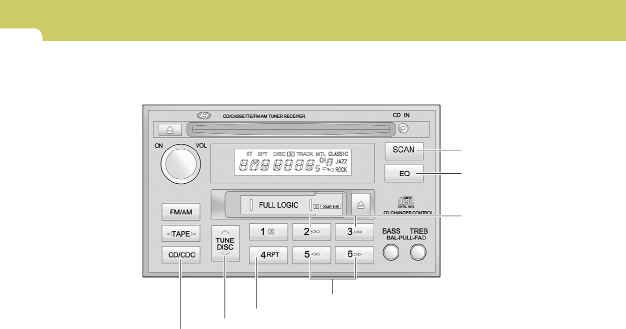
1FEATURES OF YOUR HYUNDAI
112
H290G01FC-GAT
CD AUTO CHANGER (H280) (If Installed)
H290A04GK
1. CD CHANGER Select Button
2. DISC Select Button
6. SCAN Button (If installed)
3. TRACK UP/DOWN
4. FF/REW Button
7. EQ Button
5. REPEAT
1
FEATURES OF YOUR HYUNDAI
113
B290H01GK-GAT
The CD auto changer is located in the right side
of the quater trim.
o To use the CD auto changer.
1. Open the sliding lid of the CD auto changer.
2. To eject the compact disc magazine, press
the EJECT button located inside the CD auto
changer.
3. Insert the discs into the magazine.
4. Push the magazine into the CD auto changer
and close the sliding lid.
o The CD auto changer can be used when the
ignition switch is in either "ON" or "ACC"
position.
1. CD CHANGER Select Button
When the CD changer magazine contains discs,
press the "CD/CDC" button and the CD changer
can be used even if the radio or cassette player
is being used. The Hyundai CD changer can
hold up to eight discs. The disc number will be
lit, and the track number, and elapsed time will
be displayed.
2. DISC Select Button
To select the CD you want, push " " to change
the disc number.
3. TRACK UP/DOWN
o The desired track on the disc currently being
played can be selected using the track
number.
o Press once to skip forward to the beginn-
ing of the next track. Press once to skip
back to the beginning of the track.
4. FF/REW ( / )
If you want to fast forward or reverse through
the compact disc track, push and hold in the FF
( ) or REW ( ) button.
When you release the button, the compact disc
player will resume playing.
5. REPEAT
o To repeat the music you are listening to,
press the RPT button. To cancel, press
again.
o If you do not release RPT operation when the
track ends, it will automatically be replayed.
This process will be continued until you push
the button again.
6. SCAN Button (If installed)
o Press the SCAN button to playback the first
10 seconds of each track.
o Press the SCAN button again within 10 sec.
for the desired track.
7. EQ Button
Press the EQ button to select the CLASSIC,
JAZZ, ROCK and DEFEAT MODE for the
desired tone quality. Each press of the button
changes the display as follows;
TUNE
DISC
CLASSIC → JAZZ → ROCK → DEFEAT
NOTE:
o When replacing the fuse, replace it with
a fuse having the correct capacity.
o This equipment is designed to be used
only in a 12 volt DC battery system with
negative ground.
o This unit is made of precision parts. Do
not attempt to disassemble or adjust
any parts.
o When driving your vehicle, be sure to
keep the volume of the unit set low
enough to allow you to hear sounds
coming from the outside.

1FEATURES OF YOUR HYUNDAI
114
CAUTION:
o Do not insert warped or poor quality
discs into the changer as damage to the
unit may occur.
o Do not insert anything like coins into the
changer slot as damage to the unit may
occur.
o Do not place beverages close to the
audio system. The playback mechanism
may be damaged if you spill them.
o Do not impact on the audio system, or
the playback mechanism could be dam-
aged.
o Driving off-road or other vibrations may
skip your compact disc.
Do not use the audio system off-road as
the discs could be scratched and dam-
aged.
o Do not grip or pull out the disc with your
hand while the disc is being pulled into
the unit by the self loading mechanism.
These can cause disc scratching to oc-
cur or trouble in the compact disc
changer.
o Avoid using CD-Recordable or CD-
Rewritable to ensure proper operation.
When using the compact disc changer,
genuine CDs are recommended.
!
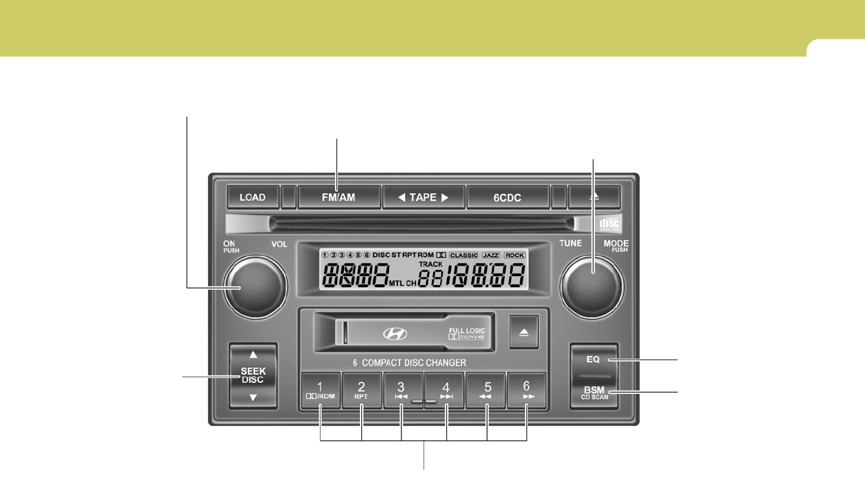
1
FEATURES OF YOUR HYUNDAI
115
6. EQ Button
J290A01JM-GAT
STEREO RADIO OPERATION (J290) (If installed)
J290A01JM
1. POWER ON/OFF/VOLUME Control Knob
2. BAND Select Button
3. SEEK Select Button
4. PRESET STATION Select Buttons
5. BEST STATION
MEMORY
7. TUNE Select Knob /
MODE Select Knob

1FEATURES OF YOUR HYUNDAI
116
CLASSIC → JAZZ → ROCK → DEFEAT
J290B01JM-GAT
1. POWER ON-OFF/VOLUME
Control Knob
The radio unit may be operated when the ignition
key is in the "ACC" or "ON" position. Press the
button to switch the power on. The display
shows the radio frequency in the radio mode,
the tape direction indicator in the tape mode, or
CD track in the CD AUTO CHANGER mode. To
switch the power off, press the button again.
VOLUME Control
Rotate the knob clockwise to increase the
volume and turn the knob counterclockwise to
reduce the volume.
2. BAND Selector
Pressing the button changes the AM, FM1 and
FM2 bands. The mode selected is shown on the
display.
3. SEEK Select Button
(Automatic Channel Selection)
Press the SEEK select button 1 sec. or more.
When the ( ) side is pressed, the unit will
automatically tune to the next higher frequency
and when the ( ) side is pressed, it will
automatically tune to the next lower frequency.
o When completed, any preset station may be
recalled by selecting AM, FM1 or FM2 band
and the appropriate station button.
5. Best Station Memory Button
(BSM)
When the BSM button is pressed for two sec-
onds or longer, the six channels from the high-
est field intensity are selected next and stored
in memory. The stations selected are stored in
the sequence frequency from the first preset
key.
6. EQ Button
Press the EQ button to select the CLASSIC,
JAZZ, ROCK and DEFEAT MODE for the
desired tone quality. Each press of the button
changes the display as follows;
4. PRESET STATION Select
Buttons
Six (6) stations for AM, FM and FM2 respec-
tively can be preset in the electronic memory
circuit.
HOW TO PRESET STATIONS
Six AM and twelve FM stations may be pro-
grammed into the memory of the radio. Then, by
simply pressing the AM / FM select button and/
or one of the six station select buttons, you may
recall any of these stations instantly. To pro-
gram the stations, follow these steps:
o Press AM/FM selector to set the band for
AM, FM1 and FM2.
o Select the desired station to be stored by
seek, scan or manual tuning.
o Determine the preset station select button
you wish to use to access that station.
o Press the station select button for more than
two seconds. A select button indicator will
show in the display indicating which select
button you have depressed. The frequency
display will flash after it has been stored into
the memory. You should then release the
button, and proceed to program the next
desired station. A total of 18 stations can be
programmed by selecting one AM and two
FM station per button.
7. TUNE (Manual) Select Knob
Rotate the knob clockwise to increase the
frequency and turn the knob counterclockwise
to reduce the frequency.

1
FEATURES OF YOUR HYUNDAI
117
Mode Select Knob
Pressing the MODE button changes the BASS,
MIDDLE, TREBLE, FADER and BALANCE
mode.
The mode selected is shown on the display.
After selecting the each mode, rotate the mode
select knob clockwise or counterclockwise.
BASS Control
To increase the BASS, rotate the knob clock-
wise, while to decrease the BASS, rotate the
knob counterclockwise.
MID Control
To increase the MID, rotate the knob clockwise,
while to decrease the MID, rotate the knob
counterclockwise.
TREBLE Control
To increase the TREBLE, rotate the knob clock-
wise, while to decrease the TREBLE, rotate the
knob counterclockwise.
FAD (Fader Control)
Rotate the control knob clockwise to empha-
size rear speaker sound (front speaker sound
will be attenuated). When the control knob is
turned counterclockwise, front speaker sound
will be emphasized (rear speaker sound will be
attenuated).
BALANCE Control
Rotate the knob clockwise to emphasize right
speaker sound (left speaker sound will be
attenuated). When the control knob is turned
counterclockwise, left speaker sound will be
emphasized (right speaker sound will be at-
tenuated).
!CAUTION:
o Do not place beverages close to the
audio system. The audio system mecha-
nism may be damaged if you spill them.
o Do not impact on the audio system, or
the audio system mechanism could be
damaged.
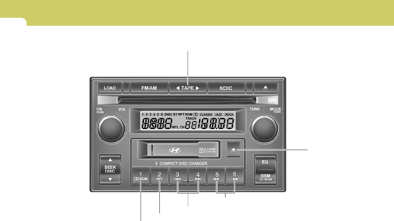
1FEATURES OF YOUR HYUNDAI
118
J290C01JM-GAT
CASSETTE TAPE PLAYER OPERATION (J290) (If installed)
J290C01JM
1.TAPE PROGRAM Button
3. DOLBY Button
4.REPEAT Button
5.AUTO MUSIC Select Button
6.FF/REW Button
2.EJECT Button

1
FEATURES OF YOUR HYUNDAI
119
J290D01JM-GAT
1. TAPE PROGRAM Button
This allows you to play the reverse side of the
tape by merely pressing the program button.
The PLAY and an arrow will appear in the display
to show tape direction.
2. EJECT Button
o When the EJECT button is pressed with a
cassette loaded, the cassette will eject.
o When the EJECT button is pressed during
FF/REW mode, the cassette will eject.
3. DOLBY Button
If you get background noise during tape PLAY,
you can reduce this considerably by merely
pressing the DOLBY button. If you want to
cancel the DOLBY feature, press the button
again.
4. REPEAT Button
o To repeat the track you are currently listen-
ing to, press the RPT button. To cancel,
press again.
o If you do not release RPT operation when the
track ends, it will automatically be replayed.
This process will be continued until you push
the button again.
5. AUTO MUSIC Select Button
Press the button to find the starting point of each
song in a prerecorded music tape. The quiet
space between songs (must have at least a 4
sec. gap) can be identified by the AUTO MUSIC
Select button.
o Pressing the will play the beginning of
the next music segment.
o Pressing the will start replay at the
beginning of the music just listened to.
o To stop FF or REW action, press the button
again.
6. FF/REW Button
o Fast forward tape winding starts when the
FF button is pressed during PLAY or REW
mode.
o PLAY starts when the FF ( ) button is
pressed again during FF mode.
o Tape rewinding starts when the REW ( )
button is pressed during PLAY or FF mode.
o PLAY starts when the REW button pressed
again during REW mode.
CAUTION:
o Do not insert anything like coins into the
player slot as damage to the unit may
occur.
o Do not place beverages close to the
audio system. The playback mechanism
may be damaged if you spill them.
o Do not impact on the audio system, or
the playback mechanism could be dam-
aged.
!
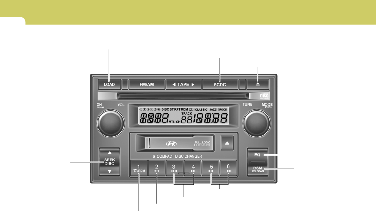
1FEATURES OF YOUR HYUNDAI
120
1.LOAD Button
J290E01JM-GAT
COMPACT DISC PLAYER / CD AUTO CHANGER OPERATION (J290) (If installed)
J290E01JM
2.Playing CD
3.EJECT Button
4. DISC Select
Button
5.RANDOM Play Button
6.REPEAT Button
7.TRACK UP/DOWN
8.FF/REW Button
9.SCAN Button
10.EQ Button

1
FEATURES OF YOUR HYUNDAI
121
J290F02JM-GAT
1. LOAD Button
This compact disc playing will accommodate up
to six discs.
To insert one disc do the following:
1. Press and release the LOAD Button.
2. Green light on both sides of the slot will be
illuminated and the will blink ten times on
the display.
3. Load a disc while the is blinking. Insert a
disc partway into the slot, label side up. The
player will pull the disc in.
NOTE:
o The disc can be only inserted while the
light is blinking.
o This CD player is suitable only for 12 cm
discs, do not use irregular shaped CDs.
When the disc is inserted, the disc will begin to
play automatically.
To insert multiple discs do the followings:
1. Press and hold the LOAD button for two
seconds or more.
You will then hear two beeps and the green
light on the both sides of the slot will be
illuminated.
2. Load a disc while the is blinking. Insert
a disc partway into the slot, label side up. The
player will pull the disc in.
Once the disc is loaded, the numbers of the
vacant disc will blink on the display continu-
ously. If the next "DISC NO." is appeared on
the display with the both side of the slot
illuminated, you can then load another disc.
3. Load the remaining disc by following the same
procedures 1 and 2.
When you finished loading 6 discs, the CD
player will begin to play the last CD loaded.
4. To load more than one disc but less than six,
complete Steps 1 and 2. When you have
finished loading discs, press LOAD button to
cancel the loading function or wait for 10
seconds. The CD player will begin to play the
last CD loaded.
As each CD starts to play, the DISC number will
appear on the display.
NOTE:
The disc player takes up to six discs. Do not
try to load more than six.
2. Playing CD
o Press the 6CDC to start CD playback,
during radio operation or cassette tape play-
ing.
o When discs are in the CD deck, if you press
the 6CDC button the CD player will begin
playing even if the radio or cassette player
is being used.
o The CD player can be used when the ignition
switch is in either the "ON" or "ACC" position.
3. EJECT Button
o When the EJECT button is pressed with
a CD loaded, the CD will eject.
o To eject all of the discs, press this button for
2 seconds or more.
4.DISC Select Button
To select the CD you want, push "DISC
" or "DISC " to change the disc number.

1FEATURES OF YOUR HYUNDAI
122
5. RANDOM Button
With random, you can listen to the tracks in
random, rather than sequential order, on all of
the discs or on one disc.
To use random, do the following:
o Press and release the RDM button to play
the tracks on all of the discs or on one disc
that are loaded, in random order. RDM will
appear in the display. Press RDM to turn if
off.
6. REPEAT Button
o To repeat the track you are currently listen-
ing to, press the RPT button. To cancel,
press again.
o If you do not release RPT operation after all
the tracks are played back, the unit will play
back again from the first track.
7. TRACK UP/DOWN
o The desired track on the disc currently being
played can be selected using the track
number.
o Press once to skip forward to the begin-
ning of the next track.
o Press once to skip back to the beginning
of the track.
8. FF/REW Button
While the disc is playing, if you hold down the FF
button continuously, the selected track is ad-
vanced. Holding down the REW button continu-
ously moves the selected track back.
9. SCAN Button
o Press the SCAN button to playback the first
10 seconds of each track.
o Press the SCAN button again within 10 sec.
when you have reached the desired track.
10. EQ Button
Press the EQ button to select the CLASSIC,
JAZZ, ROCK and DEFEAT MODE for the
desired tone quality. Each press of the button
changes the display as follows;
CLASSIC → JAZZ → ROCK → DEFEAT
NOTE:
o To assure proper operation of the unit,
keep the vehicle interior temperature
within a normal range by using the
vehicle's air conditioning or heating sys-
tem.
o When replacing the fuse, replace it with
a fuse having the correct capacity.
o The preset station frequencies are all
erased when the car battery is discon-
nected. Therefore, all data will have to be
set again if this should occur.
o Do not add any oil to the rotating parts.
Keep magnets, screwdrivers and other
metallic objects away from the tape
mechanism and head.
o This equipment is designed to be used
only in a 12 volt DC battery system with
negative ground.
o This unit is made of precision parts. Do
not attempt to disassemble or adjust
any parts.
o When driving your vehicle, be sure to
keep the volume of the unit set low
enough to allow you to hear sounds
coming from the outside.
o Do not expose this equipment (includ-
ing the speakers and tape) to water or
excessive moisture.

1
FEATURES OF YOUR HYUNDAI
123
!CAUTION:
o Do not insert warped or poor quality
discs into the CD player as damage to the
unit may occur.
o Do not insert anything like coins into the
player slot as damage to the unit may
occur.
o Do not place beverages close to the
audio system. The playback mechanism
may be damaged if you spill them.
o Do not impact on the audio system, or
the playback mechanism could be dam-
aged.
o Driving off-road or other vibrations may
skip your compact disc.
Do not use the audio system off-roads
as the discs could be scratched and
damaged.
o Do not grip or pull out the disc with your
hand while the disc is being pulled into
the unit by the self loading mechanism.
These can cause disc scratching to oc-
cur or trouble in the compact disc player.
o Avoid using CD-Recordable or CD-
Rewritable to ensure proper operation.
When using the compact disc player,
genuine CDs are recommended.

1FEATURES OF YOUR HYUNDAI
124 AUDIO FAULT CODE
INDICATION
Er2
Er3
Er6
Er8
HHH
no CD
B890A01Y-AAT
If you see any error indication in the display while using the system in the CD or Tape mode, find the cause in the chart below.
If you cannot clear the error indication, take the car to your Hyundai dealer.
SOLUTION
After resetting the audio system, push the eject button.
If disc is not ejected, consult your Hyundai dealer.
Make sure the disc is not scratched or damaged.
Press the eject button and pull out the disc.
Then insert a normal CD disc.
Check if the disc is inserted correctly in the CD player.
Make sure the disc is not scratched or damaged.
After resetting the audio system, push the eject button.
If tape does not eject, consult your Hyundai dealer.
Fault code will reset automatically when the temperature returns to normal.
Insert disc in magazine or insert CD magazine in the auto changer.
CAUSE
CD DECK MECHANICAL ERROR
(EJECT ERROR, LOADING ERROR)
FOCUS ERROR
DATA READ ERROR
DISC ERROR
TAPE DECK ERROR
TAPE EJECT ERROR
TEMPERATURE IS TOO HIGH
NO DISC IN MAGAZINE
NO CD MAGAZINE IN THE AUTO CHANGER
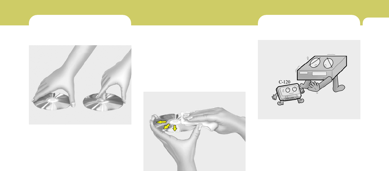
1
FEATURES OF YOUR HYUNDAI
125
CARE OF CASSETTE TAPESCARE OF DISCS
B850A02F-AAT
Proper Handling
B850A01L
Handle your disc as shown. Do not drop the
disc. Hold the disc so you will not leave finger-
prints on the surface. If the surface is scratched,
it may cause the pickup to skip signal tracks. Do
not affix tape, paper, or gummed labels on the
disc. Do not write on the disc.
Damaged Disc
Do not attempt to play damaged, warped or
cracked discs. These could severely damage
the playback mechanism.
Storage
When not in use, place your discs in their
individual case and store them in a cool place
away from the sun, heat, and dust.
Do not grip or pull out the disc with your hand
while the disc is being pulled into the unit by the
self loading mechanism.
Keep Your Discs Clean
B850A02L
Fingerprints, dust, or soil on the surface of a disc
could cause the pickup to skip signal tracks.
Wipe the surface clean with a clean soft cloth.
If the surface is heavily soiled, dampen a clean
soft cloth in a solution of mild neutral detergent
to wipe it clean.
B860A01A-AAT
Proper care of your cassette tapes will extend
the tape life and increase your listening enjoy-
ment. Always protect your tapes and cassette
cases from direct sunlight, severely cold and
dusty conditions. When not in use, cassettes
should always be stored in the original protec-
tive cassette case. When the vehicle is very hot
or cold, allow the interior temperature to become
more comfortable before listening to your cas-
settes.
B860A01L
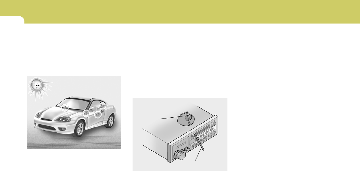
1FEATURES OF YOUR HYUNDAI
126
Head
Cotton applicator
HGK062
B860A02L
o Never leave a cassette inserted in the player
when not being played. This could damage
the tape player unit and the cassette tape.
o We strongly recommend against the use of
tapes longer than C-60 (60 minutes total).
Tapes such as C-120 or C-180 are very thin
and do not perform as well in the automotive
environment.
o The playback head, capstan and pinch roll-
ers will develop a coating of tape residue that
can result in deterioration of sound quality,
such as a wavering sound. They should be
cleaned monthly using a commercially avail-
able head cleaning tape or special solution
available from audio specialty shops. Follow
the supplier's directions carefully and never
oil any part of the tape player unit.
o Always be sure that the tape is tightly wound
on its reel before inserting in the player.
Rotate a pencil in the drive sprockets to wind
up any slack.
o Be sure that the cassette label is not loose
or peeling off or tape ejection may be difficult.
o Never touch or soil the actual audio tape
surfaces.
o Keep all magnetized objects, such as elec-
tric motors, speakers or transformers away
from your cassette tapes and tape player
unit.
o Store cassettes in a cool, dry place with the
open side facing down to prevent dust from
setting in the cassette body.
o Avoid repeated fast reverse usage to replay
one given tune or tape section. This can
cause poor tape winding to occur, and even-
tually cause excessive internal drag and
poor audio quality in the cassette. If this
occurs, it can sometimes be corrected by
fast winding the tape from end to end several
times. If this does not correct the problem, do
not continue to use the tape in your vehicle.
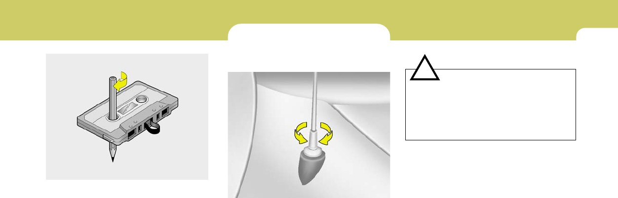
1
FEATURES OF YOUR HYUNDAI
127
!
ANTENNA
B860A03L
NOTE:
Look at a tape before you insert it.
If the tape is loose, tighten it by turning one
of the hubs with a pencil or your finger.
If the label is peeling off, do not put it in the
drive mechanism.
Do not leave tapes sitting where they are
exposed to hot, warm, or high humidity,
such as on top of the dashboard or in the
player.
If a tape is exposed to excessively hot or
cold, let it reach a moderate temperature
before putting it in the player.
B870A01A-AAT
Fixed Rod Antenna
Your car uses a fixed rod antenna to receive
both AM and FM broadcast signals.
This antenna is a removable type. To remove
the antenna, turn it counterclockwise. To install
the antenna, turn it clockwise.
CAUTION:
o Be sure to remove the antenna before
washing the car in an automatic car
wash or it may be damaged.
o When reinstalling your antenna, it is
important that it is fully tightened to
ensure proper reception.
B870A01A

DRIVING YOUR HYUNDAI
2
Engine Exhaust Can Be Dangerous! ............................ 2-2
Before Starting the Engine ............................................ 2-3
Key Positions ................................................................ 2-4
Starting .......................................................................... 2-5
Operating the Manual Transaxle ................................... 2-6
Automatic Transaxle ..................................................... 2-8
Anti-Lock Brake System (ABS) .................................. 2-12
Good Braking Practices .............................................. 2-12
Electronic Stability Program (ESP) ............................. 2-13
Driving for Economy ................................................... 2-15
Winter Driving ............................................................. 2-16
Trailer or Vehicle Towing ............................................ 2-19
Vehicle Load Limit ....................................................... 2-22
2

2DRIVING YOUR HYUNDAI
2
WARNING: ENGINE EXHAUST CAN BE DANGEROUS!
C010A01GK-AAT
Engine exhaust fumes can be extremely dangerous. If, at any time, you smell exhaust fumes inside the vehicle, open the windows immediately.
o Do not inhale exhaust fumes.
Exhaust fumes contain carbon monoxide, a colorless, odorless gas that can cause unconsciousness and death by asphyxiation.
o Be sure the exhaust system does not leak.
The exhaust system should be checked whenever the vehicle is raised to change the oil or for any other purpose. If you hear a change
in the sound of the exhaust or if you drive over something that strikes the underneath side of the car, have the exhaust system checked
as soon as possible by your Hyundai dealer.
o Do not run the engine in an enclosed area.
Letting the engine idle in your garage, even with the garage door open, is a hazardous practice. Never run the engine in your garage any
longer than it takes to start the engine and back the car out.
o Avoid idling the engine for prolonged periods with people inside the car.
If it is necessary to idle the engine for a prolonged period with people inside the car, be sure to do so only in an open area with the air intake
set at "Fresh" and fan operating at one of the higher speeds so fresh air is drawn into the interior.
If you must drive with the tail gate open because you are carrying objects that make this necessary:
1. Close all windows.
2. Open side vents.
3. Set the air intake control at "Fresh", the air flow control at "Floor" or "Face" and the fan at one of the higher speeds.
To assure proper operation of the ventilation system, be sure the ventilation air intakes located just in front of the windshield are kept clear
of snow, ice, leaves or other obstructions.
!
!PROPOSITION 65 WARNING:
Engine exhaust and a wide variety of automobile components and parts, including components found in the interior furnishings in a vehicle,
contain or emit chemicals known to the State of California to cause cancer and birth defects and reproductive harm. In addition, certain fluids
contained in vehicles and certain products of component wear contain or emit chemicals known to the State of California to cause cancer
and birth defects or other reproductive harm.

2
DRIVING YOUR HYUNDAI
3
BEFORE STARTING THE ENGINE
C020A02A-AAT
Before you start the engine, you should always:
1. Look around the vehicle to be sure there are
no flat tires, puddles of oil, water or other
indications of possible trouble.
2. After entering the car, check to be sure the
parking brake is engaged.
3. Check that all windows, and lights are clean.
4. Check that the interior and exterior mirrors
are clean and in position.
5. Check your seat, seatback and headrest to
be sure they are in their proper positions.
6. Close all the doors.
7. Fasten your seat belt and be sure that all
other occupants have fastened theirs.
8. Turn off all lights and accessories that are
not needed.
9. When you turn the ignition switch to "ON",
check that all appropriate warning lights are
operating and that you have sufficient fuel.
10.Check the operation of warning lights and all
bulbs when key is in the "ON" position.
TO START THE ENGINE
C030A01A-AAT
COMBINATION IGNITION SWITCH
o If your Hyundai is equipped with a manual
transaxle, place the shift lever in neutral and
depress the clutch pedal fully.
o If your Hyundai has an automatic transaxle,
place the shift lever in "P" (park).
o To start the engine, insert the ignition key and
turn it to the "START" position. Release it as
soon as the engine starts. Do not hold the
key in the "START" position for more than 15
seconds.
NOTE:
o For safety, the engine will not start if the
clutch pedal is not depressed fully
(Manual transaxle) or the shift lever is
not in "P" or "N" Position (Automatic
transaxle).
o The ignition key cannot be turned from
"ACC" position to "LOCK" position un-
less the shift lever is in the "P" (Park)
position or the negative battery terminal
is disconnected from the battery. To
remove the key, always confirm that the
shift lever is securely positioned in "P"
(Park) (For Automatic transaxle)
o For additional information about start-
ing, see page 2-5.
!WARNING:
o All passengers must be properly belted
whenever the vehicle is moving. Refer to
pages: 1-16 through 1-20 for more infor-
mation on their proper use.
o Always check the surrounding areas near
your vehicle for people, especially chil-
dren, before putting a car into 'drive.'
!WARNING:
Always wear appropriate shoes when oper-
ating your vehicle.
Unsuitable shoes (high heels, ski boots,
etc.) may interfere with your
ability to use the brake and accelerator
pedal, and the clutch (if installed).
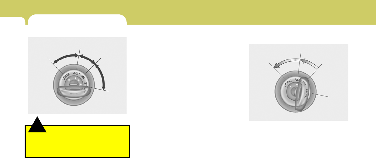
2DRIVING YOUR HYUNDAI
4
C070C03A-AAT
To Remove the Ignition Key
NOTE:
Do not hold the key in the "START" position
for more than 15 seconds.
o "ON"
When the key is in the "ON" position, the ignition
is on and all accessories may be turned on. If
the engine is not running, the key should not be
left in the "ON" position. This will discharge the
battery and may also damage the ignition sys-
tem.
o "ACC"
With the key in the "ACC" position, some elec-
trical accessories (radio, etc.) may be oper-
ated.
o "LOCK"
The key can be removed or inserted in this
position. To protect against theft, the steering
wheel locks by removing the key.
NOTE:
If difficulty is experienced in turning the
ignition key to the START position, turn the
steering wheel right and left to release the
tension and then turn the key.
1. Turn the ignition key counterclockwise from
the "ACC" position to the "LOCK" position.
2. The key can be removed in the "LOCK"
position.
C070C01E-1
LOCK
ACC
ON
START
!
KEY POSITIONS
C040A02A-AAT
WARNING:
The engine should not be turned off or the
key removed from the ignition key cylinder
while the vehicle is in motion. The steering
wheel is locked by removing the key.
o "START"
The engine is started in this position. It will crank
until you release the key.
C040A01E-1
LOCK
ACC
ON
START
2
DRIVING YOUR HYUNDAI
5
STARTING
!
C050A01A-AAT
WARNING:
Never run the engine in a closed or poorly
ventilated area any longer than is needed to
move your car in or out of the area. The
carbon monoxide gas emitted is odorless
and can cause serious injury or death.
C050A01E-1
LOCK ON
START
C050B02JM-AAT
NORMAL CONDITIONS:
The Starting Procedure:
1. Insert key, and fasten the seat belt.
2. Depress the clutch pedal fully and place the
gearshift lever (manual transaxle) in neutral
or the selector lever (automatic transaxle) in
"P" (park) position.
3. After turning the ignition key to the "ON"
position, make certain all warning lights and
gauges are functioning properly before start-
ing the engine.
WARNING:
Be sure that the clutch is fully depressed
when starting a manual transaxle vehicle.
Your manual transaxle equipped vehicle
will not start unless the clutch pedal is fully
depressed.
!
4. Turn the ignition key to the "Start" position
and release it when the engine starts.
After the engine has started, allow the engine
to run for 10 to 20 seconds prior to placing
the vehicle in gear.
The starter should not be operated for more
than 15 seconds at a time. Wait 15-30 sec-
onds between starting attempts to protect
the starter from overheating.
!WARNING:
Always fully depress the brake pedal before
and while shifting out of the "P" Park posi-
tion into another position to avoid inad-
vertent motion of the vehicle which could
injure persons in or around the car.
2DRIVING YOUR HYUNDAI
6
CAUTION:
When downshifting from fifth gear to fourth
gear, caution should be taken not to inad-
vertently press the gear shift lever sideways
in such a manner that second gear is en-
gaged. Such a drastic downshift may cause
the engine speed to increase to the point
that the tachometer will enter the red zone.
Such over-revving of the engine may cause
engine damage.
!
o If you 've come to a complete stop and
it's hard to shift into 1st or R(Reverse),
put the shift lever in N(Neutral) position
and release the clutch. Press the clutch
pedal down, and then shift into 1st or
R(Reverse) gear position.
o Do not use the shift lever as a handrest
during driving, as this can result in pre-
mature wear of the transaxle shift forks.
OPERATING THE MANUAL
TRANSAXLE
C070A02GK-AAT
Your Hyundai's manual transaxle has a con-
ventional shift pattern. This shift pattern is im-
printed on the shift knob. The transaxle is fully
synchronized in all forward gears so shifting to
either a higher or a lower gear is easily accom-
plished.
HGK3023
Type A Type B
When shifting into reverse gear, pull the mis-
shift prevention tab and shift into reverse gear
position. (B Type: 6 speed type)
NOTE:
o To shift into reverse, rest the lever in
neutral for at least 3 seconds after your
car is completely stopped. Then move
the lever into the reverse position.
o During cold weather, shifting may be
difficult until the transaxle lubricant has
warmed up. This is normal and not harm-
ful to the transaxle.
HGK3024
Type B
Mis-shift
prevention
tab

2
DRIVING YOUR HYUNDAI
7
C070B01A-AAT
Using the Clutch
The clutch should be pressed all the way to the
floor before shifting, then released slowly. The
clutch pedal should always be fully returned to
the original position. Do not rest your foot on the
clutch pedal while driving. This can cause un-
necessary wear.
Do not partially engage the clutch to hold the car
on an incline. This causes unnecessary wear.
Use the foot brake or parking brake to hold the
car on an incline. Do not operate the clutch pedal
rapidly and repeatedly.
C070D04A-AAT
Good Driving Practices
o Never take the car out of gear and coast
down a hill. This is extremely hazardous.
Always leave the car in gear.
o Don't "ride" the brakes. This can cause them
to overheat and malfunction. Instead, when
you are driving down a long hill, slow down
and shift to a lower gear. When you do this,
engine braking will help slow the car.
o Slow down before shifting to a lower gear.
This will help avoid over-revving the engine,
which can cause damage.
o Slow down when you encounter cross winds.
This gives you much better control of your
car.
o Be sure the car is completely stopped before
you attempt to shift into reverse. The
transaxle can be damaged if you do not. To
shift into reverse, depress the clutch, move
the shift lever to neutral, wait three seconds,
then shift to the reverse position.
o Exercise extreme caution when driving on a
slippery surface. Be especially careful when
braking, accelerating or shifting gears. On a
slippery surface, an abrupt change in ve-
hicle speed can cause the drive wheels to
lose traction and the vehicle to go out of
control.
!WARNING:
o Always buckle-up! In a collision, an
unbelted occupant is significantly more
likely to be seriously injured or killed
than a properly belted occupant.
o Avoid high speeds when cornering or
turning.
o Do not make quick steering wheel move-
ments, such as sharp lane changes or
fast, sharp turns.
o The risk of rollover is greatly increased if
you lose control of your vehicle at high-
way speeds.
o Loss of control often occurs if two or
more wheels drop off the roadway and
the driver oversteers to reenter the road-
way.
o In the event your vehicle leaves the road-
way, do not steer sharply. Instead, slow
down before pulling back into the travel
lanes.
o Never exceed posted speed limits.
2DRIVING YOUR HYUNDAI
8
The first few shifts on a new vehicle, or if the
battery has been disconnected, may be
somewhat abrupt. This is a normal condi-
tion, and the shifting sequence will adjust
after shifts are cycled a few times by the
T.C.M (Transaxle Control Module).
HGK3040
!CAUTION:
Never shift into "R" or "P" position while the
vehicle is moving.
C070E01GK-AAT
RECOMMENDED SHIFT POINTS
The shift points as shown below are recom-
mended for optimum fuel economy and perfor-
mance.
Shift
from-to
1-2
2-3
3-4
4-5
Recommended
15 mph (20 km/h)
25 mph (40 km/h)
35 mph (55 km/h)
45 mph (75 km/h)
Shift
from-to
1-2
2-3
3-4
4-5
5-6
Recommended
10 mph (15 km/h)
20 mph (35 km/h)
30 mph (50 km/h)
45 mph (70 km/h)
60 mph (95 km/h)
Type A (5 speed)
Type B (6 speed)
AUTOMATIC TRANSAXLE
C090A03Y-AAT
The highly efficient Hyundai automatic transaxle
has four forward speeds and one reverse
speed. The individual speeds are selected au-
tomatically, depending on the position of the
speed selector lever. The selector lever has 2
gates; the main gate and the manual gate.
NOTE:
For information on manual gate operation,
refer to "Sports Mode".
In the main gate, the selector lever has 4
positions, and is equipped with a button to avoid
inadvertent selection.
HGK3025
2
DRIVING YOUR HYUNDAI
9
!
C090B01A-AAT
The function of each position is as fol-
lows:
o P (Park):
Use to hold the vehicle in place when parked or
while starting the engine. Whenever parking the
car, apply the parking brake and shift the selec-
tor lever to the "P" (Park) position.
CAUTION:
Never place the selector lever in the "P"
(Park) position unless the vehicle is fully
stopped. Failure to observe this caution
will cause severe damage to the transaxle.
NOTE:
Depress the brake pedal and push
the button when shifting.
Push the button when shifting.
The selector lever can be shifted
freely.
The indicator lights in the instrument cluster
indicate the selector lever position when the
ignition is switched "ON". During the sports
mode operation, the gear currently in use dis-
plays in the numeral indicator.
C090E01O-AAT
o D(Drive):
Use for normal driving. The transaxle will auto-
matically shift through a four gear sequence.
C090D02O-AAT
o N (Neutral):
In the "N" position, the transaxle is in neutral,
which means that no gears are engaged. The
engine can be started with the shift lever in "N"
position, although this is not recommended
except if the engine stalls while the car is
moving.
C090C01A-AAT
o R(Reverse):
Use for backing up the vehicle. Bring the car to
a complete stop before shifting the selector
lever to "R" position.
C090F02GK-GAT
Sports Mode
Whether the vehicle is stationary or in motion,
sports mode is selected by pushing the selector
lever from the "D" position into the manual gate.
To return to "D" range operation, push the
selector lever back into the main gate.
In sports mode, moving the selector lever back-
wards and forwards can make rapid gearshifts
simple. In contrast to a manual transaxle, the
sports mode allows gearshifts with the accel-
erator pedal depressed.
UP (+) : Push the lever forward once to shift up
one gear.
DOWN (-) : Pull the lever backwards once to
shift down one gear.
HGK3027

2DRIVING YOUR HYUNDAI
10
!
C090I03L-GAT
CAUTION:
o Shift into "R" and "P" position only when
the vehicle has completely stopped.
o Do not accelerate the engine in reverse
or any of the forward positions with the
brakes applied.
o Always apply the footbrake when shift-
ing from "P" or "N", to "R", "D"position.
o Do not use the "P" (Park) position in
place of the parking brake. Always set
the parking brake, shift the transaxle
into "P" (Park) position and turn off the
ignition when you leave the vehicle, even
momentarily. Never leave the vehicle
unattended while the engine is running.
o Check the automatic transaxle fluid level
regularly, and add fluid as necessary.
o When accelerating from a stop on a
steep hill, the vehicle may have a ten-
dency to roll backwards. Shifting the
shift lever into 2nd gear while in Sport
mode will help prevent the vehicle from
rolling backwards.
o See the maintenance schedule for the
proper fluid recommendation.
!CAUTION:
o In sports mode, the driver must execute
shifts in accordance with prevailing road
conditions, taking care to keep the en-
gine speed below the red zone.
o For engine protection, upward shifts are
made automatically when the engine
rpm reaches the red zone.
o By rapidly moving the selector lever
backwards (-) twice it is possible to skip
one gear by using the sports mode.
Since sudden engine braking and/or
rapid acceleration can cause a loss of
traction, however, downshifts must be
made carefully in accordance with the
vehicle's speed.
NOTE:
o In sports mode, only the four forward
gears can be selected. To select reverse
or park, move the selector lever to the "R"
or "P" position as required.
o In sports mode, downward shifts are
made automatically when the vehicle
slows down. When the vehicle stops, 1st
gear is automatically selected.
o To maintain the required levels of ve-
hicle performance and safety, the sys-
tem may not execute certain gearshifts
when the selector lever is operated.
o Before driving away from a stop on a
slippery road, push the selector lever
forward into the +(UP) position. This
causes the transaxle to shift into 2nd
gear which is better for smooth driving
away on a slippery road. Push the selec-
tor lever to the -(DOWN) side to shift
back to 1st gear.
C090H01L-GAT
NOTE:
o For smooth and safe operation, depress
the brake pedal when shifting from "Neu-
tral" position or "Park" position to a
forward or reverse gear.
o The ignition key must be in the "ON"
position and the brake pedal fully de-
pressed in order to move the shift lever
from the "P" (Park) position to any of the
other positions.
o It is always possible to shift from "R",
"N", "D" position to "P" position. The
vehicle must be fully stopped to avoid
transaxle damage.

2
DRIVING YOUR HYUNDAI
11
C090N05O-AAT
Good Driving Practices
o Never move the gear selector lever from "P"
or "N" to any other position with the accelera-
tor pedal depressed.
o Never move the gear selector lever into "P"
when the vehicle is in motion.
o Be sure the car is completely stopped before
you attempt to shift into "R".
o Never take the car out of gear and coast
down a hill. This may be extremely hazard-
ous. Always leave the car in gear when
moving.
o Do not "ride" the brakes. This can cause
them to overheat and malfunction. Instead,
when you are driving down a long hill, slow
down and shift to a lower gear. When you do
this, engine braking will help slow the car.
o Slow down before shifting to a lower gear.
Otherwise, the lower gear may not be en-
gaged.
o Always use the parking brake. Do not de-
pend on placing the transaxle in "P" to keep
the car from moving.
o Exercise extreme caution when driving on a
slippery surface. Be especially careful when
braking, accelerating or shifting gears. On a
slippery surface, an abrupt change in ve-
hicle speed can cause the drive wheels to
lose traction and the vehicle to go out of
control.
!WARNING:
o Always buckle-up! In a collision, an
unbelted occupant is significantly more
likely to be seriously injured or killed
than a properly belted occupant.
o Avoid high speeds when cornering or
turning.
o Do not make quick steering wheel move-
ments, such as sharp lane changes or
fast, sharp turns.
o The risk of rollover is greatly increased if
you lose control of your vehicle at high-
way speeds.
o Loss of control often occurs if two or
more wheels drop off the roadway and
the driver oversteers to reenter the road-
way.
o In the event your vehicle leaves the road-
way, do not steer sharply. Instead, slow
down before pulling back into the travel
lanes.
o Never exceed posted speed limits.
o Optimum vehicle performance and economy
is obtained by smoothly depressing and
releasing the accelerator pedal. WARNING:
If your vehicle becomes stuck in snow,
mud, sand, etc., then you may attempt to
rock the vehicle free by moving it forward
and backward. Do not attempt this proce-
dure if people or objects are anywhere near
the vehicle. During the rocking operation
the vehicle may suddenly move forward or
backward as it becomes unstuck, causing
injury or damage to nearby people or ob-
jects.
!

2DRIVING YOUR HYUNDAI
12 GOOD BRAKING PRACTICES
!
C130A02A-AAT
WARNING:
o Whenever leaving vehicle or parking,
always set the parking brake as far as
possible and fully engage the vehicle's
transaxle into the park position. Ve-
hicles not fully engaged in park with the
parking brake set are at risk for moving
inadvertently and injuring yourself or
others.
o All vehicles should always have the park-
ing brake fully engaged when parking to
avoid inadvertent movement of the car
which can injure occupants or pedestri-
ans.
o Nothing should be carried on top of the
shelf panel behind the rear seat. If there
were an accident or a sudden stop, such
objects could move forward and cause
damage to the vehicle or injure the occu-
pants.
!
ANTI-LOCK BRAKE SYSTEM (ABS)
C120A03A-AAT
(If installed)
The Anti-Lock Brake System (ABS) is designed
to prevent wheel lock-up during sudden braking
or on hazardous road surfaces. The ABS con-
trol module monitors the wheel speed and con-
trols the pressure applied to each brake. Thus,
in emergency situations or on slick roads, ABS
will increase vehicle control during braking.
NOTE:
o A click sound may be heard in the engine
compartment when the vehicle begins
to move after the engine is started. These
conditions are normal and indicate that
the anti-lock brake system (Electronic
Stability Program) is functioning prop-
erly.
o During ABS operation, a slight pulsation
may be felt in the brake pedal when the
brakes are applied. Also, a noise may be
heard in the engine compartment while
braking. These conditions are normal
and indicate that the anti-lock brake
system is functioning properly.
WARNING:
ABS will not prevent accidents due to im-
proper or dangerous driving maneuvers.
Even though vehicle control is improved
during emergency braking, always main-
tain a safe distance between you and ob-
jects ahead. Vehicle speeds should always
be reduced during extreme road condi-
tions.
The braking distance for cars equipped
with an anti-lock braking system may be
longer than for those without it in the
following road conditions.
During these conditions the vehicle should
be driven at reduced speeds.
o Rough, gravel or snow-covered roads.
o With tire chains installed.
o Roads where the road surface is pitted or
has different surface height.
The safety features of an ABS equipped
vehicle should not be tested by high speed
driving or cornering. This could endanger
the safety of yourself or others.

2
DRIVING YOUR HYUNDAI
13
o If your car is equipped with an automatic
transaxle, don’t let your car creep forward.
To avoid creeping forward, keep your foot on
the brake pedal when the car is stopped.
o Use caution when parking on a hill. Firmly
engage the parking brake and place the gear
selector lever in "P" (automatic transaxle) or
in first or reverse gear (manual transaxle).
If your car is facing downhill, turn the front
wheels into the curb to help keep the car from
rolling. If your car is facing uphill, turn the front
wheels away from the curb to help keep the
car from rolling. If there is no curb or if it is
required by other conditions to keep the car
from rolling, block the wheels.
o Under some conditions your parking brake
can freeze in the engaged position. This is
most likely to happen when there is an
accumulation of snow or ice around or near
the rear brakes or if the brakes are wet. If
there is a risk that the parking brake may
freeze, apply it only temporarily while you put
the gear selector lever in "P" (automatic) or
in first or reverse gear (manual transaxle)
and block the rear wheels so the car cannot
roll. Then release the parking brake.
o Do not hold the vehicle on the upgrade with
the accelerator pedal. This can cause the
transmission to overheat. Always use the
brake pedal or parking brake.
o After being parked, check to be sure the
parking brake is not engaged and that the
parking brake indicator light is out before
driving away.
o Driving through water may get the brakes
wet. They can also get wet when the car is
washed. Wet brakes can be dangerous!
Your car will not stop as quickly if the brakes
are wet. Wet brakes cause the car to pull to
one side. To dry the brakes, apply the
brakes lightly while driving slowly until the
braking action returns to normal, taking care
to keep the car under control at all times. If
the braking action does not return to normal,
stop as soon as it is safe to do so and call your
Hyundai dealer for assistance.
o Don’t coast down hills with the car out of gear.
This is extremely hazardous. Keep the car
in gear at all times, use the brakes to slow
down, then shift to a lower gear so that engine
braking will help you maintain a safe speed.
o Don’t "ride" the brake pedal. Resting your
foot on the brake pedal while driving can be
dangerous because it can result in the brakes
overheating and losing their effectiveness. It
also increases the wear of the brake com-
ponents.
o If a tire goes flat while you are driving, apply
the brakes gently and keep the car pointed
straight ahead while you slow down. When
you are moving slowly enough for it to be safe
to do so, pull off the road and stop in a safe
place.
ELECTRONIC STABILITY
PROGRAM (ESP)
C310A02JM-AAT
(If installed)
!WARNING:
Never drive too fast for the road conditions
or too quickly when cornering. Electronic
stability control (ESP) will not prevent acci-
dents. Excessive speed in turns, abrupt
maneuvers and hydroplaning on wet sur-
faces can still result in serious accidents.
Only a safe and attentive driver can prevent
accidents by avoiding maneuvers that
cause the vehicle to lose traction. Even with
ESP installed, always follow all the normal
precautions for driving - including driving
at safe speeds for the conditions.
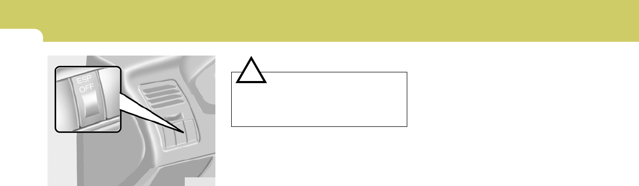
2DRIVING YOUR HYUNDAI
14
HGK3033-1
The Electronic Stability Program (ESP) system
is designed to stabilize the vehicle during cor-
nering manuevers. ESP checks where you are
steering and where the vehicle is actually going.
ESP applies the brakes at individual wheels and
intervenes in the engine management system
to stabilize the vehicle.
The Electronic Stability Program (ESP) system
is an electronic system designed to help the
driver maintain vehicle control under adverse
conditions. It is not a substitute for safe driving
practices. Factors including speed, road con-
ditions and driver steering input can all affect
whether ESP will be effective in preventing a
loss of control. It is still your responsibility to
drive and corner at reasonable speeds and to
leave a sufficient margin of safety.
CAUTION:
Driving with varying tire or wheel size may
cause the ESP system to malfunction. When
replacing tires, make sure they are the same
size as your original tires.
!
C310B01JM-AAT
ESP ON/OFF Mode
When the ESP is operating, the ESP indicator in
the instrument cluster will blink.
If you turn the system off by pressing the ESP
switch, the ESP-OFF indicator will come on and
stay on. In the ESP-OFF mode, the stability
control will be deactivated. Adjust your driving
accordingly. To turn the system back on, press
the switch again. The ESP-OFF indicator should
go off.
NOTE:
The ESP mode will automatically be turned
ON after the engine is turned off and re-
started.

2
DRIVING YOUR HYUNDAI
15
DRIVING FOR ECONOMY
C140A02A-AAT
You can save fuel and get more miles from your
car if you follow these suggestions:
o Drive smoothly. Accelerate at a moderate
rate. Don't make "jack-rabbit" starts or full-
throttle shifts and maintain a steady cruising
speed. Don't race between stoplights. Try to
adjust your speed to that of the other traffic
so you don't have to change speeds unnec-
essarily. Avoid heavy traffic whenever pos-
sible. Always maintain a safe distance from
other vehicles so you can avoid unneces-
sary braking. This also reduces brake wear.
o Drive at a moderate speed. The faster you
drive, the more fuel your car uses. Driving at
a moderate speed, especially on the high-
way, is one of the most effective ways to
reduce fuel consumption.
o Don't "ride" the brake or clutch pedal. This
can increase fuel consumption and also
increase wear on these components. In
addition, driving with your foot resting on the
brake pedal may cause the brakes to over-
heat, which reduces their effectiveness and
may lead to more serious consequences.
o Take care of your tires. Keep them inflated
to the recommended pressure. Incorrect
inflation, either too much or too little, results
in unnecessary tire wear. Check the tire
pressures at least once a month.
o Be sure that the wheels are aligned cor-
rectly. Improper alignment can result from
hitting curbs or driving too fast over irregular
surfaces. Poor alignment causes faster tire
wear and may also result in other problems
as well as greater fuel consumption.
o Keep your car in good condition. For better
fuel economy and reduced maintenance
costs, maintain your car in accordance with
the maintenance schedule in Section 5. If
you drive your car in severe conditions,
more frequent maintenance is required (see
Section 5 for details).
o Keep your car clean. For maximum service,
your Hyundai should be kept clean and free
of corrosive materials. It is especially impor-
tant that mud, dirt, ice, etc. not be allowed to
accumulate on the underside of the car. This
extra weight can result in increased fuel
consumption and also contribute to corro-
sion.
o Travel lightly. Don't carry unnecessary
weight in your car. Weight reduces fuel
economy.
o Don't let the engine idle longer than neces-
sary. If you are waiting (and not in traffic),
turn off your engine and restart only when
you're ready to go.
o Remember, your Hyundai does not require
extended warm-up. After the engine has
started, allow the engine to run for 10 to 20
seconds prior to placing the vehicle in gear.
In very cold weather, however, give your
engine a slightly longer warm-up period.
C310D01JM-AAT
Indicators and Warning
The indicators should illuminate when the igni-
tion key is turned to ON or START but should
go out after three seconds.
If the indicators do not illuminate, or the ESP or
ESP-OFF indicator does not go out after 3
seconds, have the vehicle checked by an
authorized dealer.
Should there be any unusual conditions in the
device while driving, ESP-OFF indicator illumi-
nates as a warning.
If ESP-OFF indicator illuminates, pull your car
to a safe place and stop the engine.
Then, start the engine again to check if the ESP-
OFF indicator goes out.
If the indicator remains lit even after the engine
has been started, have your car checked by an
authorized Hyundai dealer.

2DRIVING YOUR HYUNDAI
16
o Don't "lug" or "over-rev" the engine. Lugging
is driving too slowly in too high a gear result-
ing in the engine bucking. If this happens,
shift to a lower gear. Over-revving is racing
the engine beyond its safe limit. This can be
avoided by shifting at the recommended
speeds.
o Use your air conditioning sparingly. The air
conditioning system is operated by engine
power so your fuel economy is reduced
when you use it.
SMOOTH CORNERING
C150A01A-AAT
Avoid braking or gear changing in corners,
especially when roads are wet. Ideally, corners
should always be taken under gentle accelera-
tion. If you follow these suggestions, tire wear
will be held to a minimum.
WINTER DRIVING
C160A01A-AAT
The more severe weather conditions of winter
result in greater wear and other problems. To
minimize the problems of winter driving, you
should follow these suggestions:
C160B01A-AAT
Snowy or Icy Conditions
To drive your vehicle in deep snow, it may be
necessary to use snow tires or to install tire
chains on your tires. If snow tires are needed,
it is necessary to select tires equivalent in size
and type to the original equipment tires. Failure
to do so may adversely affect the safety and
handling of your car. Speeding, rapid accelera-
tion, sudden brake applications, and sharp
turns are potentially very hazardous practices.
During deceleration, use engine braking to the
fullest extent. Sudden brake applications on
snowy or icy roads may cause skids to occur.
You need to keep sufficient distance between
the vehicle in front and your vehicle. Also, apply
the brake gently. It should be noted that installing
tire chains on the tire will provide a greater
driving force, but will not prevent side skids.
NOTE:
Tire chains are not legal in all states. Check
state laws before fitting tire chains.

2
DRIVING YOUR HYUNDAI
17
C160H02A-AAT
Use Approved Window Washer Anti-
Freeze in System
To keep the water in the window washer system
from freezing, add an approved window washer
anti-freeze solution in accordance with instruc-
tions on the container. Window washer anti-
freeze is available from Hyundai dealers and
most auto parts outlets. Do not use engine
coolant or other types of anti-freeze as these
may damage the paint finish.
C160I01A-AAT
Don’t Let Your Parking Brake Freeze
Under some conditions your parking brake can
freeze in the engaged position. This is most
likely to happen when there is an accumulation
of snow or ice around or near the rear brakes
or if the brakes are wet. If there is a risk the
parking brake may freeze, apply it only tempo-
rarily while you put the gear selector lever in "P"
(automatic) or in first or reverse gear (manual
transaxle) and block the rear wheels so the car
cannot roll. Then release the parking brake.
C160C01A-AAT
Use High Quality Ethylene Glycol Cool-
ant
Your Hyundai is delivered with high quality
ethylene glycol coolant in the cooling system. It
is the only type of coolant that should be used
because it helps prevent corrosion in the cool-
ing system, lubricates the water pump and
prevents freezing. Be sure to replace or replen-
ish your coolant in accordance with the main-
tenance schedule in Section 5. Before winter,
have your coolant tested to assure that its
freezing point is sufficient for the temperatures
anticipated during the winter.
C160D01F-AAT
Check Battery and Cables
Winter puts additional burdens on the battery
system. Visually inspect the battery and cables
as described in Section 6 (See page 6-23). The
level of charge in your battery can be checked
by your Hyundai dealer or a service station.
C160E01A-AAT
Change to "Winter Weight" Oil if Neces-
sary
In some climates it is recommended that a lower
viscosity "winter weight" oil be used during cold
weather. See Section 9 for recommendations.
If you aren’t sure what weight oil you should use,
consult your Hyundai dealer.
C160F01F-AAT
Check Spark Plugs and Ignition System
Inspect your spark plugs as described in Sec-
tion 6 (See page 6-10) and replace them if
necessary. Also check all ignition wiring and
components to be sure they are not cracked,
worn or damaged in any way.
C160G01A-AAT
To Keep Locks from Freezing
To keep the locks from freezing, squirt an
approved de-icer fluid or glycerine into the key
opening. If a lock is covered with ice, squirt it with
an approved de-icing fluid to remove the ice. If
the lock is frozen internally, you may be able to
thaw it out by using a heated key. Handle the
heated key with care to avoid injury.

2DRIVING YOUR HYUNDAI
18 HIGHER SPEED MOTORING
C160J01A-AAT
Don’t Let Ice and Snow Accumulate
Underneath
Under some conditions, snow and ice can build
up under the fenders and interfere with the
steering. When driving in severe winter condi-
tions where this may happen, you should peri-
odically check underneath the car to be sure the
movement of the front wheels and the steering
components is not obstructed.
C160K01A-AAT
Carry Emergency Equipment
Depending on the severity of the weather where
you drive your car, you should carry appropri-
ate emergency equipment. Some of the items
you may want to carry include tire chains, tow
straps or chains, flashlight, emergency flares,
sand, a shovel, jumper cables, a window scraper,
gloves, ground cloth, coveralls, a blanket, etc.
C170A02A-AAT
Pre-Trip Inspections
1. Tires:
Adjust the tire inflation pressures to specifica-
tion. Low tire inflation pressures will result in
overheating and possible failure of the tires.
Avoid using worn or damaged tires which may
result in reduced traction or tire failure.
NOTE:
Never exceed the maximum tire inflation
pressure shown on the tires.
2. Fuel, engine coolant and engine oil:
High speed travel consumes more fuel than
urban motoring. Do not forget to check both
engine coolant and engine oil.
3. Drive belt:
A loose or damaged drive belt may result in
overheating of the engine.
!WARNING:
o Underinflated or overinflated tires can
cause poor handling, loss of vehicle
control, and sudden tire failure leading
to accidents, injuries, and even death.
Always check tires are properly inflated
before driving. Refer to pages 8-2~8-3
for proper tire pressures and further
information.
o Driving on tires with no or insufficient
tread is dangerous. Worn-out tires can
result in loss of vehicle control, colli-
sions, injury, and even death. Worn-out
tires should be replaced as soon as
possible and should never be used for
driving. Always check tire tread before
driving your car.

2
DRIVING YOUR HYUNDAI
19
C190C03S-AAT
Trailer Brakes
If your trailer is equipped with a braking system,
make sure it conforms to federal and/or local
regulations and that it is properly installed and
operating correctly.
NOTE:
If you tow a trailer or vehicle, your car will
require more frequent maintenance due to
the additional load. See "Maintenance Un-
der Severe Usage Conditions" on page 5-6.
TRAILER OR VEHICLE TOWING
C190A01S-AAT
If you are considering towing with your car, you
should first check with your State's Department
of Motor Vehicles to determine their legal re-
quirements.
Since laws vary from State to State, the require-
ments for towing trailers, cars, other types of
vehicles, or apparatus may differ. Ask your
Hyundai dealer for further details before towing.
CAUTION:
Do not do any towing with your car during
its first 1,200 miles (2,000 km) in order to
allow the engine to properly break in. Fail-
ure to heed this caution may result in seri-
ous engine or transaxle damage.
!
C190B01S-AAT
Trailer Hitches
Select the proper hitch and ball combination,
making sure that its location is compatible with
that of the trailer or vehicle being towed. Use a
quality non-equalizing hitch which distributes
the tongue load uniformly throughout the chas-
sis.
The hitch should be bolted securely to the car
and installed by a qualified technician. DO NOT
USE A HITCH DESIGNED FOR TEMPORARY
INSTALLATION AND NEVER USE ONE THAT
ATTACHES ONLY TO THE BUMPER.
C180A01A-AAT
Check your lights regularly for correct opera-
tion and always keep them clean. When driving
during the day in conditions of poor visibility, it
is helpful to drive with headlights on low beam.
This enables you to be seen, as well as to see.
USE OF LIGHTS
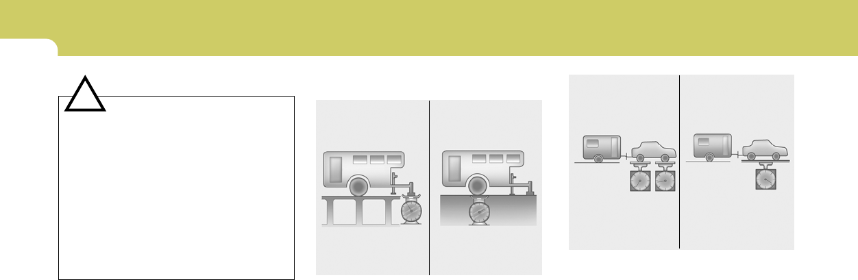
2DRIVING YOUR HYUNDAI
20
C190D01S-AAT
Safety Chains
Should the hitch connection between your
vechile and the trailer or vehicle you are towing
fail, the trailer or vehicle could wander danger-
ously across other lanes of traffic and ultimately
leave the roadway. To eliminate this potentially
dangerous situation, safety chains, attached
between your car and the trailer or towed
vehicle, are required in most states.
C190E02GK-AAT
Trailer Weight Limit
C190E01L
Tongue load Total trailer weight
Tongue loads can be increased or decreased
by redistributing the load in the trailer.
This can be verified by checking the total weight
of the loaded trailer and then checking the load
on the tongue.
NOTE:
1. Never load the trailer with more weight in
the back than in the front. About 60% of
the trailer load should be in the front half
on the trailer and the remaining 40% in
the rear.
2. The total gross vehicle weight with trailer
must not exceed the Gross Vehicle
Weight Rating (GVWR) shown on the
vehicle identification plate (see page 8-
1). The total gross vehicle weight is the
combined weight of the vehicle, driver,
all passengers and their luggage, cargo,
hitch, trailer tongue load and other op-
tional equipment.
3. The front or rear axle weight must not
exceed the Gross Axle Weight Rating
(GAWR) shown on the vehicle identifi-
cation plate (see page 8-2). It is possible
that your towing package does not ex-
ceed the GVWR but exceeds the GAWR.
Improper trailer loading and/or too much
luggage in the trunk can overload the
rear axle. Redistribute the load and check
the axle weight again.
C190E02L
Gross axle weight Gross vehicle weight
CAUTION:
o Never connect a trailer brake system
directly to the vehicle brake system.
o When towing a trailer on steep grades (in
excess of 6%) pay close attention to the
engine coolant temperature gauge to
ensure the engine does not overheat. If
the needle of the coolant temperature
gauge moves across the dial towards
"H" (HOT), pull over and stop as soon as
it is safe to do so, and allow the engine
to idle until it cools down. You may
proceed once the engine has cooled
sufficiently.
!

2
DRIVING YOUR HYUNDAI
21
(automatic). In addition, place wheel chocks
at each of the trailer's tires.
9. If the trailer has electric brakes, start your
vehicle and trailer moving, and then apply the
trailer brake controller by hand to be sure the
brakes are working. This lets you check
your electrical connection at the same time.
10.During your trip, occasionally check to be
sure that the load is secure, and that the
lights and any trailer brakes are still working.
11.Avoid jerky starts, sudden acceleration or
sudden stops.
12.Avoid sharp turns and rapid lane changes.
13.Avoid holding the brake pedal down too long
or too frequently. This could cause the brakes
to overheat, resulting in reduced braking
efficiency.
14.When going down a hill, shift into a lower gear
and use the engine braking effect.
When ascending a long grade, downshift the
transaxle to a lower gear and reduce speed
to reduce chances of engine overloading
and/or overheating.
15.If you have to stop while going uphill, do not
hold the vehicle in place by pressing on the
accelerator. This can cause the automatic
transaxle to overheat. Use the parking brake
or footbrake.
NOTE:
When towing check transaxle fluid more
frequently.
CAUTION:
The following specifications are recom-
mended when towing a trailer. The loaded
trailer weight cannot safely exceed the val-
ues in the chart below.
!
!WARNING:
o Improperly loading your vehicle and
trailer can seriously affect its steering
and braking performance causing a
crash which could cause serious injury
or death.
o Towing a trailer affected vehicle han-
dling and braking.
o Drive more slowly when towing a trailer
and allow more distance when braking.
o Be careful when driving in slippery and
windy conditions.
o Be careful when turning and while driv-
ing up and down hills.
Lbs. (kg)
Maximum Towable Weight
Trailer
1000 (453)
Tongue
100 (45)
C190F01S-AAT
Trailer or Vehicle Towing Tips
1. Before towing, check hitch and safety chain
connections as well as proper operation of
the trailer running lights, brake lights, and
turn signals.
2. Always drive your vehicle at a moderate
speed. (Less than 60 mph)
3. Trailer towing requires more fuel than normal
conditions.
4. To maintain engine braking efficiency and
electrical charging performance, do not use
fifth gear (manual transaxle) or overdrive
(automatic transaxle).
5. Always secure items in the trailer to prevent
load shift while driving.
6. Check the condition and air pressure of all
tires on the trailer and your car. Low tire
pressure can seriously affect the handling.
Also check the spare tire.
7. The vehicle/trailer combination is more af-
fected by crosswind and buffeting.
When being passed by a large vehicle, keep
a constant speed and steer straight ahead.
If there is too much wind buffeting, slow down
to get out of the other vehicle's air turbulence.
8. When parking your car and trailer, especially
on a hill, be sure to follow all the normal
precautions. Turn your front wheel into the
curb, set the parking brake firmly, and put the
transaxle in 1st or Reverse (manual) or Park

2DRIVING YOUR HYUNDAI
22
CAUTION:
If overheating should occur when towing,
(the temperature gauge reads near red zone),
taking the following action may reduce or
eliminate the problem.
1. Turn off the air conditioner.
2. Reduce highway speed.
3. Select a lower gear when going uphill.
4. While in stop and go traffic, place the
gear selector in park or neutral and idle
the engine at a higher speed.
!
VEHICLE LOAD LIMIT
C190F01GK-AAT
Tire and Loading Information Label
I030B01GK
The tire label located on the driver's
side of the center pillar outer panel
gives the original tire size, cold tire
pressures recommended for your ve-
hicle, the number of people that can be
in your vehicle and vehicle capacity
weight.
Vehicle capacity weight:
700 lbs (317 kg)
Vehicle capacity weight is the maxi-
mum combined weight of occupants
and cargo. If your vehicle is equipped
with a trailer, the combined weight in-
cludes the tongue load.
Seating capacity:
Total: 4 persons
(Front seat: 2 persons,
Rear seat: 2 persons)
Seating capacity is the maximum num-
ber of occupants including a driver,
your vehicle may carry.
However the seating capacity may be
reduced based upon the weight of all of
the occupants, and the weight of the
cargo being carried or towed. Do not
overload the vehicle as there is a limit
to the total weight, or load limit including
occupants and cargo, the vehicle can
carry.
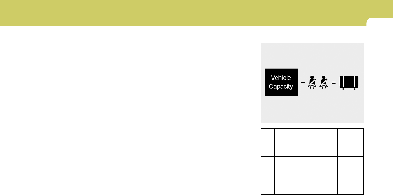
2
DRIVING YOUR HYUNDAI
23
C190F01JM
Total
1400 lbs
(635 kg)
300 lbs
(136 kg)
1100 lbs
(498 kg)
Example 1
Item
A
B
C
Description
Vehicle Capacity Weight
Subtract Occupant Weight
150 lbs (68 kg) × 2
Available Cargo and
Luggage weight
(3)Subtract the combined weight of the
driver and passengers from XXX
kilograms or XXX pounds.
(4)The resulting figure equals the avail-
able amount of cargo and luggage
load capacity. For example, if the
"XXX" amount equals 1400 lbs, and
there will be five 150 lb. passengers
in your vehicle, the amount of avail-
able cargo and luggage load capac-
ity is 650 lbs. (1400-750 (5 x 150) =
650 lbs.)
(5)Determine the combined weight of
luggage and cargo being loaded on
the vehicle. That weight may not
safely exceed the available cargo
and luggage load capacity calcu-
lated in Step 4.
(6)If your vehicle will be towing a trailer,
load from your trailer will be trans-
ferred to your vehicle. Consult this
manual to determine how this re-
duces the available cargo and lug-
gage load capacity of your vehicle.
ABC
Towing capacity:
Towing capacity is the maximum trailer
weight including its cargo weight, your
vehicle can tow. See the section "Trailer
or Vehicle Towing" for specifications
about the trailer weight.
Cargo capacity:
The cargo capacity of your vehicle will
increase or decrease depending on the
weight and the number of occupants
and the tongue load, if your vehicle is
equipped with a trailer.
Steps for Determining Correct Load
Limit
(1)Locate the statement "The combined
weight of occupants and cargo should
never exceed XXX pounds'' on your
vehicle's placard.
(2)Determine the combined weight of
the driver and passengers that will be
riding in your vehicle.
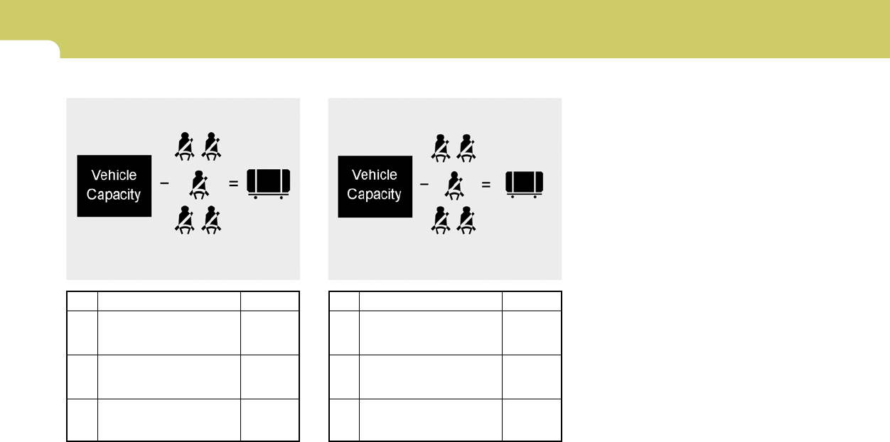
2DRIVING YOUR HYUNDAI
24
C190F03JM
Total
1400 lbs
(635 kg)
860 lbs
(390 kg)
540 lbs
(245 kg)
Item
A
B
C
Description
Vehicle Capacity Weight
Subtract Occupant Weight
172 lbs (68 kg) x 5
Available Cargo Weight
Example 3 Refer to your vehicle's tire and loading
information label for specific informa-
tion about your vehicle's capacity weight
and seating positions. The combined
weight of the driver, passengers and
cargo should never exceed your
vehicle's capacity weight.
ABC
C190F02JM
Example 2
Total
1400 lbs
(635 kg)
750 lbs
(340 kg)
650 lbs
(295 kg)
Item
A
B
C
Description
Vehicle Capacity Weight
Subtract Occupant Weight
150 lbs (68 kg) x 5
Available Cargo and
Luggage Weight
ABC
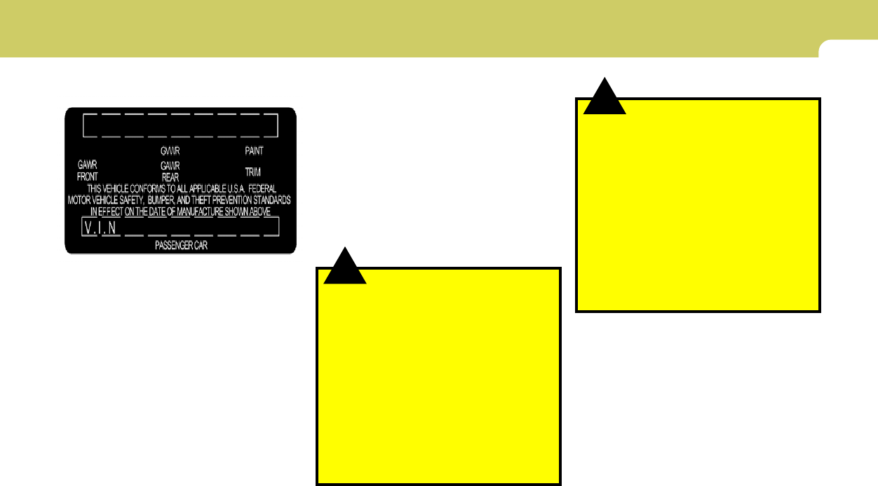
2
DRIVING YOUR HYUNDAI
25
!
!
This label also tells you the maximum
weights that can be supported by the
front and rear axles, called Gross Axle
Weight Rating (GAWR). To find out the
actual loads on your front and rear
axles, you need to go to a weigh station
and weigh your vehicle. Your dealer can
help you with this. Be sure to spread out
your load equally on both sides of the
centerline.
WARNING:
o Never exceed the GVWR for your
vehicle, the GAWR for either the
front or rear axle and vehicle ca-
pacity weight. Exceeding these rat-
ings can cause an accident or
vehicle damage. You can calcu-
late the weight of your load by
weighing the items (or people)
before putting them in the vehicle.
Be careful not to overload your
vehicle.
C190G03JM-AAT
Compliance Label
The compliance label is located on the
driver's side of the center piller outer
panel.
The label shows the maximum allow-
able weight of the fully loaded vehicle.
This is called the GVWR (Gross Ve-
hicle Weight Rating). The GVWR in-
cludes the weight of the vehicle, all
occupants, fuel and cargo.
C190G01A
WARNING:
o Do not load your vehicle any
heavier than the GVWR, either the
maximum front or rear GAWR and
vehicle capacity weight. If you do,
parts, including tires on your ve-
hicle can break, and it can change
the way your vehicle handles and
braking ability. This could cause
you to lose control and crash.
Also, overloading can shorten the
life of your vehicle.

2DRIVING YOUR HYUNDAI
26
! ! WARNING:
Items you carry inside your vehicle
can strike and injure people in a
sudden stop or turn, or in a crash.
o Put things in the cargo area of
your vehicle. Try to spread the
weight evenly.
o Never stack items, like suitcases,
inside the vehicle above the tops
of the seats.
o Do not leave an unsecured child
restraint in your vehicle.
o When you carry something inside
the vehicle, secure it.
o Do not drive with a seat folded
down unless necessary.
NOTE:
o Overloading your vehicle may
cause damage. Repairs would not
be covered by your warranty. Do
not overload your vehicle.
o Using heavier suspension com-
ponents to get added durability
might not change your weight rat-
ings. Ask your dealer to help you
load your vehicle the right way.
The label will help you decide how much
cargo and installed equipment your
vehicle can carry.
If you carry items inside your vehicle –
like suitcases, tools, packages, or any-
thing else – they more as fast as the
vehicle goes. If you have to stop or turn
quickly, or if there is a crash, the items
will keep going and can cause an injury
if they strikes the driver or a passenger.
WARNING:
o Overloading your vehicle can
cause heat buildup in your
vehicle's tires and possible tire
failure that could lead to a crash.
o Overloading your vehicle can
cause increased stopping dis-
tances that could lead to a crash.
o A crash resulting from poor han-
dling vehicle damage, tire failure,
or increased stopping distances
could result in serious injury or
death.

If the Engine will not Start .............................................. 3-2
Jump Starting ................................................................ 3-3
If the Engine Overheats ................................................ 3-4
Spare Tire ..................................................................... 3-5
If You Have a Flat Tire .................................................. 3-6
Changing a Flat Tire ...................................................... 3-6
If Your Vehicle Must be Towed ................................... 3-12
Emergency Towing ..................................................... 3-13
If You Lose Your Keys ................................................ 3-14
WHAT TO DO IN AN EMERGENCY
3
3

3
2
WHAT TO DO IN AN EMERGENCY
IF THE ENGINE WILL NOT START
!
D010A01A-AAT D010B02A-AAT
If Engine Doesn’t Turn Over or Turns
Over Slowly
D010C02Y-AAT
If Engine Turns Over Normally but Does
Not Start
1. Check fuel level.
2. With the key in the "OFF" position, check all
connectors at ignition, coils and spark plugs.
Reconnect any that may be disconnected or
loose.
3. Check the fuel line in the engine compart-
ment.
4. If the engine still does not to start, call a
Hyundai dealer or seek other qualified assis-
tance.
D010D01A-AAT
If the Engine Stalls While Driving
1. Reduce your speed gradually, keeping a
straight line. Move cautiously off the road to
a safe place.
2. Turn on your emergency flashers.
3. Try to start the engine again. If your vehicle
will not start, contact a Hyundai dealer or
seek other qualified assistance.
WARNING:
If the engine will not start, do not push or
pull the car to start it. This could result in a
collision or cause other damage. In addi-
tion, push or pull starting may cause the
catalytic converter to be overloaded and
create a fire hazard.
1. If your car has an automatic transaxle, be
sure the gear selector lever is in "N" or "P"
and the emergency brake is set.
2. Check the battery connections to be sure
they are clean and tight.
3. Turn on the interior light. If the light dims or
goes out when you operate the starter, the
battery is discharged.
4. Check the starter connections to be sure
they are securely tightened.
5. Do not push or pull the vehicle to start it. See
instructions for "Jump Starting".
D010B01GK
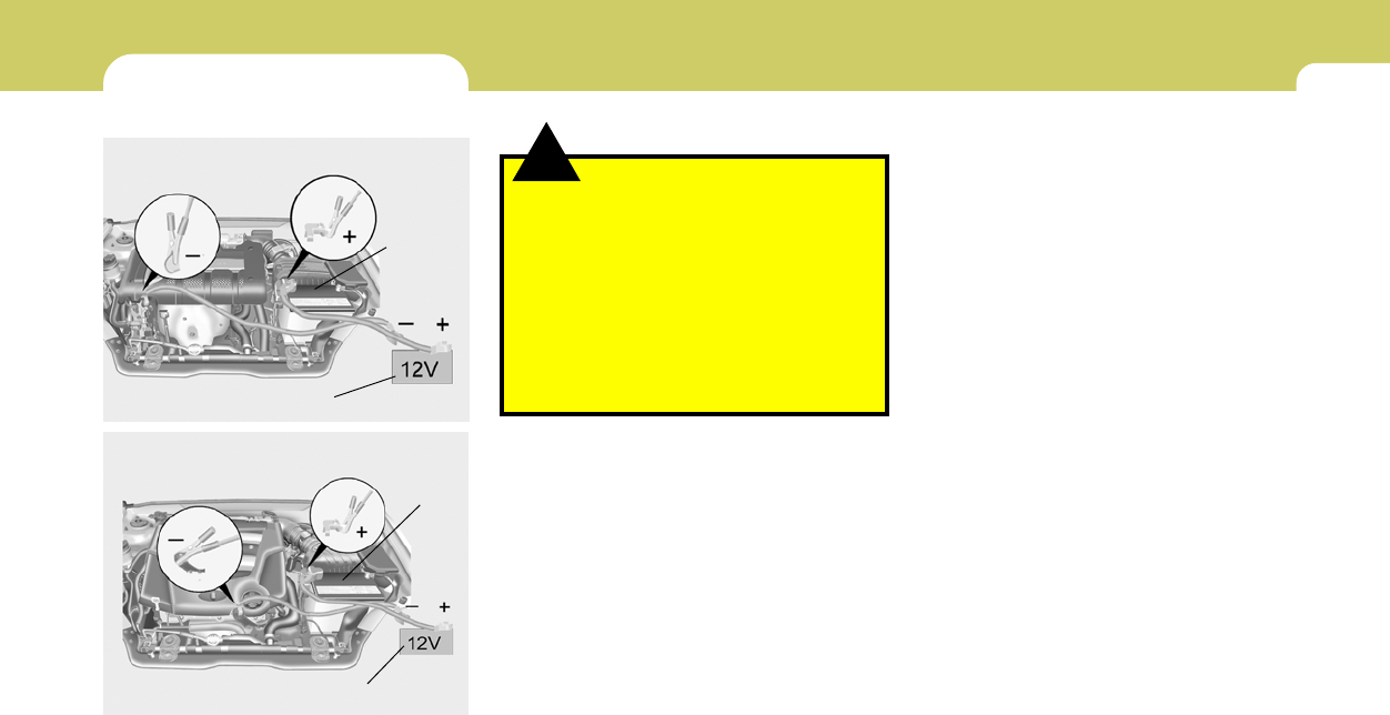
3
WHAT TO DO IN AN EMERGENCY
3
JUMP STARTING
!
o To jump start a car with a discharged battery,
follow this procedure exactly:
1. If the booster battery is installed in another
vehicle, be sure the two vehicles are not
touching.
2. Turn off all unnecessary lights and acces-
sories in both vehicles.
3. Attach the clamps of the jumper cable in the
exact location shown on the previous page.
First, attach one clamp of the jumper cable
to the positive (+) post or cable of the dis-
charged battery. Then attach the other end
of the same cable to the positive (+) post or
cable of the booster battery. Next, using the
other cable, attach one clamp to the negative
(-) post or cable of the booster battery. Then
attach the other end of that cable to a solid
metal part of the engine of the vehicle with the
discharged battery away from the battery.
Do not connect the cable to any moving part.
4. Start the engine in the car with the booster
battery and let it run for a few minutes. This
will help to assure that the booster battery is
fully charged. During the jumping operation,
run the engine in this vehicle at about 2,000
rpm.
5. Start the engine in the car with the dis-
charged battery using the normal starting
procedure. After the engine starts, leave the
jumper cables connected and let the engine
run at fast idle or about 2000 rpm for several
minutes.
D020A03A-AAT
WARNING:
The gas produced by the battery during the
jump-start operation is highly explosive. If
these instructions are not followed exactly,
serious personal injury and damage to the
vehicle may occur! If you are not sure how
to follow this procedure, seek qualified
assistance. Automobile batteries contain
sulfuric acid. This is poisonous and highly
corrosive. When jump starting, wear pro-
tective glasses and be careful not to get
acid on yourself, your clothing or on the car.
o If you should accidentally get acid on your
skin or in your eyes, immediately remove
any contaminated clothing and flush the area
with clear water for at least 15 minutes. Then
promptly obtain medical attention. If you
must be transported to an emergency facil-
ity, continue to apply water to the affected
area with a sponge or cloth.
o The gas produced by the battery during the
jump-start operation is highly explosive. Do
not smoke or allow a spark or an open flame
in the vicinity.
o The battery being used to provide the jump
start must be 12-volt. If you cannot deter-
mine that it is a 12-volt battery, do not attempt
to use it for the jump start.
2.0L
HGK4001
HGK4002
Dis-
charged
battery
2.7L
Booster battery
Dis-
charged
battery
Booster battery

3
4
WHAT TO DO IN AN EMERGENCY
IF THE ENGINE OVERHEATS
!
!WARNING:
While the engine is running, keep hair,
hands, and clothing away from moving
parts such as the fan and drive belts to
prevent injury.
5. If the water pump drive belt is broken or
engine coolant is leaking out, stop the engine
immediately and call the nearest Hyundai
dealer for assistance.
WARNING:
Do not remove the radiator cap when the
engine is hot. This can allow coolant to be
blown out of the opening and cause seri-
ous burns.
D030A02A-AAT
If your temperature gauge indicates overheat-
ing, you experience a loss of power, or hear loud
pinging or knocking and the engine is probably
too hot. If this happens and, you should:
1. Pull off the road and stop as soon as it is safe
to do so.
2. Place the gear selector lever in "P" (auto-
matic), or neutral (manual transaxle) and set
the parking brake. If the air conditioning is on,
turn it off.
3. If engine coolant is running out under the car
or steam is coming out from the hood, stop
the engine. Do not open the hood until the
engine coolant has stopped running or the
steaming has stopped. If there is no visible
loss of engine coolant and no steam, leave
the engine running and check to be sure the
engine cooling fan is operating. If the fan is
not running, turn the engine off.
4. Check to see if the water pump drive belt is
missing. If it is not missing, check to see that
it is tight. If the drive belt seems to be
satisfactory, check for engine coolant leak-
ing from the radiator, hoses or under the car.
(If the air conditioning had been in use, it is
normal for cold water to be draining from it
when you stop).
6. Carefully remove the jumper cables in the
reverse order of attachment.
If you do not know why your battery became
discharged (because the lights were left on,
etc.), have the charging system checked by
your Hyundai dealer.
3
WHAT TO DO IN AN EMERGENCY
5
SPARE TIRE
!
6. If you cannot find the cause of the overheat-
ing, wait until the engine temperature has
returned to normal. Then, if the engine cool-
ant has been lost, carefully add water to the
reservoir (Page 6-8) to bring the fluid level in
the reservoir up to the halfway mark.
7. Proceed with caution, keeping alert for fur-
ther signs of overheating. If overheating
happens again, call a Hyundai dealer for
assistance.
CAUTION:
Serious loss of engine coolant indicates
there is a leak in the cooling system and this
should be checked as soon as possible by
a Hyundai dealer.
D040A03GK-AAT
TEMPORARY SPARE TIRE
The following instructions for the tem-
porary spare tire should be observed:
1. Check inflation pressure as soon as
practical after installing the spare
tire, and adjust to the specified pres-
sure. The tire pressure should be
periodically checked and maintained
at the specified pressure while the
tire is stored.
Tire Size
Inflation Pressure
T125/70 R16
420 kPa(60 psi)
4. As the temporary spare tire is spe-
cifically designed for your car, it
should not be used on any other
vehicle.
5. The temporary spare tire should not
be used on any other wheels, nor
should standard tires, snow tires,
wheel covers or trim rings be used
with the temporary spare wheel. If
such use is attempted, damage to
these items or other car components
may occur.
6. The temporary spare tire pressure
should be checked once a month
while the tire is stored.
2. The spare tire should only be used
temporarily and should be returned
to the luggage compartment as soon
as the original tire can be repaired or
replaced.
3. Continuous use at speeds of over 50
mph (80 km/h) is not recommended.
Spare Tire Pressure
CAUTION:
o Do not use snow chains with your
temporary spare tire.
o Do not use more than one tempo-
rary spare tire at a time.
o Do not tow a trailer while the tem-
porary spare tire is installed.
!

3
6
WHAT TO DO IN AN EMERGENCY
IF YOU HAVE A FLAT TIRE
D050A01A-AAT
If a tire goes flat while you are driving:
1. Take your foot off the accelerator
pedal and let the car slow down while
driving straight ahead. Do not apply
the brakes immediately or attempt to
pull off the road as this may cause a
loss of control. When the car has
slowed to such a speed that it is safe
to do so, brake carefully and pull off
the road. Drive off the road as far as
possible and park on firm, level
ground. If you are on a divided high-
way, do not park in the median area
between the two traffic lanes.
2. When the car is stopped, turn on your
emergency hazard flashers, set the
parking brake and put the transaxle
in "P" (automatic) or reverse (manual
transaxle).
3. Have all passengers get out of the car.
Be sure they all get out on the side of
the car that is away from traffic.
4. Change the tire following the instruc-
tions provided on the following pages.
D040B01A-AAT
Handling the Spare Tire
Remove the installation bolt to remove
the spare tire. To replace the spare tire
in its storage compartment, tighten the
bolt firmly with your fingers until there is
no more play in the spare tire.
HGK4010
!WARNING:
The temporary spare tire is for emer-
gency use only. Do not operate your
vehicle on this temporary spare at
speeds over 50 mph (80 kmh). The
original tire should be repaired or
replaced as soon as is possible to
avoid failure of the spare possibly
leading to personal injury or death.
3
WHAT TO DO IN AN EMERGENCY
7
CHANGING A FLAT TIRE
D060A02A-AAT
The procedure described on the follow-
ing pages can be used to rotate tires as
well as to change a flat tire. When
preparing to change a flat tire, check to
be sure the gear selector lever is in "P"
(automatic transaxle) or reverse gear
(manual transaxle) and that the parking
brake is set, then:
D060A01GK
D060B02GK-AAT
1. Obtain Spare Tire and Tool
Remove the spare tire and remove the
jack and tool bag from the trunk.
HGK4008 The jack is located behind the right side
of luggage trim. Remove the jack cover
by unscrewing the bolts. Turn the jack
end counterclockwise to lower the jack
height by using a screw driver or wrench
bar and remove it from the bracket.
HGK4009
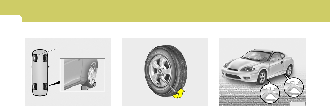
3
8
WHAT TO DO IN AN EMERGENCY
D060E01A-AAT
4. Put the Jack in Place
The base of the jack should be placed
on firm, level ground. The jack should
be positioned as shown in the drawing.
HGK4012
D060D02A-AAT
3. Loosen Wheel Nuts
The wheel nuts should be loosened
slightly before raising the car. To loosen
the nuts, turn the wrench handle coun-
terclockwise. When doing this, be sure
that the socket is seated completely
over the nut so it cannot slip off. For
maximum leverage, position the wrench
so the handle is to the left as shown in
the drawing. Then, while holding the
wrench near the end of the handle, push
down on it with steady pressure. Do not
remove the nuts at this time. Just
loosen them about one-half turn.
HGK4013
D060C01A-AAT
2. Block the Wheel
Block the wheel that is diagonally oppo-
site from the flat to keep the vehicle
from rolling when the car is raised on the
jack.
HGK4011
Flat tire
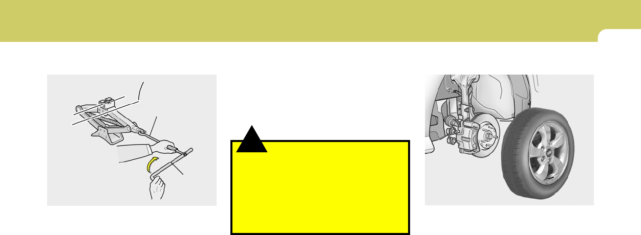
3
WHAT TO DO IN AN EMERGENCY
9
!WARNING:
Do not get under the car when it is
supported by the jack! This is very
dangerous as the jack could fall and
cause serious injury or death. No
one should stay in the car while the
jack is being used.
D060F02E-AAT
5. Raising the Car
After inserting a bar into the wheel nut
wrench, install the bar into the jack as
shown in the drawing. To raise the
vehicle, turn the jack handle clockwise.
As the jack begins to raise the vehicle,
double check that it is properly posi-
tioned and will not slip. If the jack is on
soft ground or sand, place a board,
brick, flat stone or other object under
the base of the jack to keep it from
sinking.
HFC4022
Wrench bar
Wheel nut
wrench
D060G02Y-AAT
6. Changing Wheels
Loosen the wheel nuts and remove
them with your fingers. Slide the wheel
off the studs and lay it flat so it cannot
roll away. To put the wheel on the hub,
pick up the spare tire, line up the holes
with the studs and slide the wheel onto
them. If this is difficult, tip the wheel
slightly and get the top hole in the wheel
lined up with the top stud. Then jiggle
the wheel back and forth until the wheel
can be slid over the other studs.
HGK4031
Raise the car high enough so that the
fully inflated spare tire can be installed.
To do this, you will need more ground
clearance than is required to remove
the flat tire.
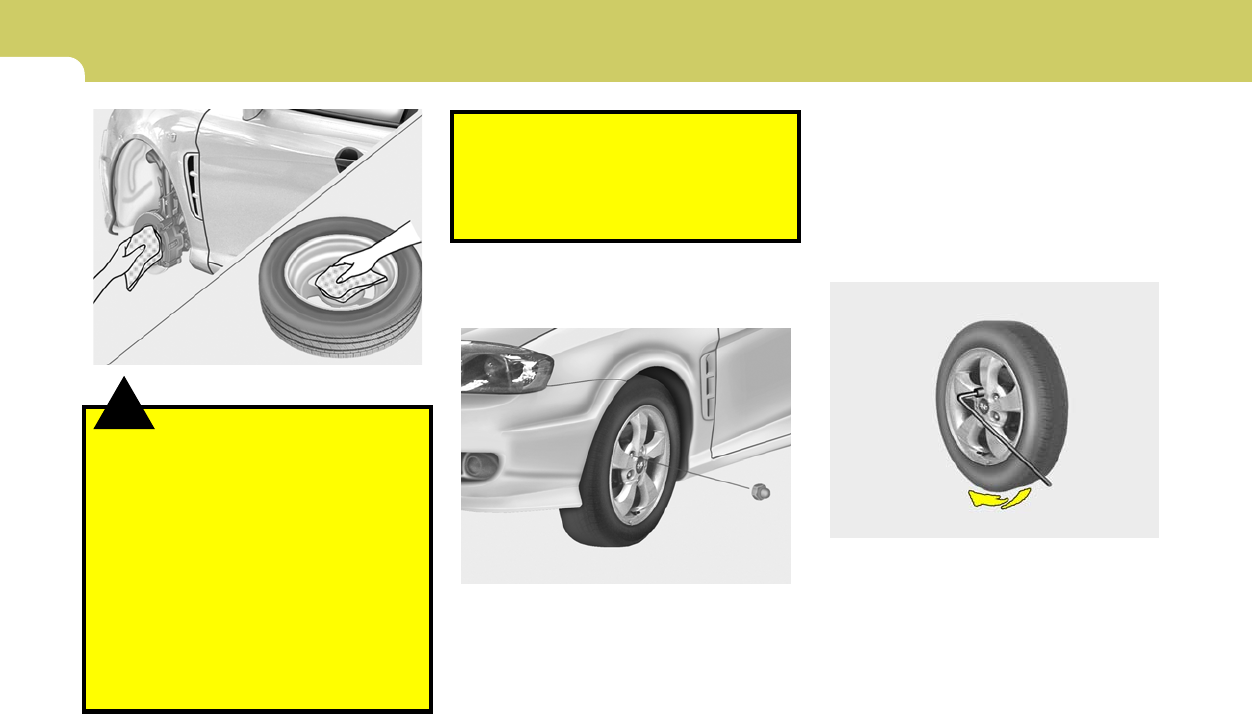
3
10
WHAT TO DO IN AN EMERGENCY
D060I01E-AAT
8. Lower Vehicle and Tighten Nuts
Lower the car to the ground by turning
the wheel nut wrench counterclock-
wise. Then position the wrench as shown
in the drawing and tighten the wheel
nuts. Be sure the socket is seated
completely over the nut. Do not stand
HGK4014
D060H02Y-AAT
7. Reinstall Wheel Nuts
To reinstall the wheel, hold it on the
studs, put the wheel nuts on the studs
and tighten them finger tight. The nuts
should be installed with their small di-
D060H01GK
wheel nuts could come loose and
cause the loss of a wheel. Loss of a
wheel may result in loss of control of
the vehicle. This may cause serious
injury or death.
ameter ends directed inward. Jiggle the
tire to be sure it is completely seated,
then tighten the nuts as much as pos-
sible with your fingers again.
!WARNING:
Wheels and wheel covers may have
sharp edges. Handle them carefully
to avoid possible severe injury. Be-
fore putting the wheel into place, be
sure that there is nothing on the hub
or wheel (such as mud, tar, gravel,
etc.) that interferes with the wheel
from fitting solidly against the hub. If
there is, remove it. If there is not
good contact on the mounting sur-
face between the wheel and hub, the
D060G02GK

3
WHAT TO DO IN AN EMERGENCY
11
D060J01FC-GAT
After Changing Wheels
If you have a tire gauge, remove the
valve cap and check the air pressure. If
the pressure is lower than recom-
mended, drive slowly to the nearest
service station and inflate to the correct
pressure. If it is too high, adjust it until
it is correct. Always reinstall the valve
cap after checking or adjusting tire
pressure. If the cap is not replaced, air
may leak from the tire. If you lose a
valve cap, buy another and install it as
soon as possible.
HGK4032
on the wrench handle or use an exten-
sion pipe over the wrench handle.
Go around the wheel tightening every
other nut until they are all tight. Then
double-check each nut for tightness.
After changing wheels, have a techni-
cian tighten the wheel nuts to their
proper torque as soon as possible.
Wheel nut tightening torque:
Steel wheel & aluminium alloy wheel:
65-80 lb.ft (900-1,100kg.cm)
After you have changed wheels, al-
ways secure the flat tire in its place in
the luggage compartment and return
the jack and tools to their proper stor-
age locations.
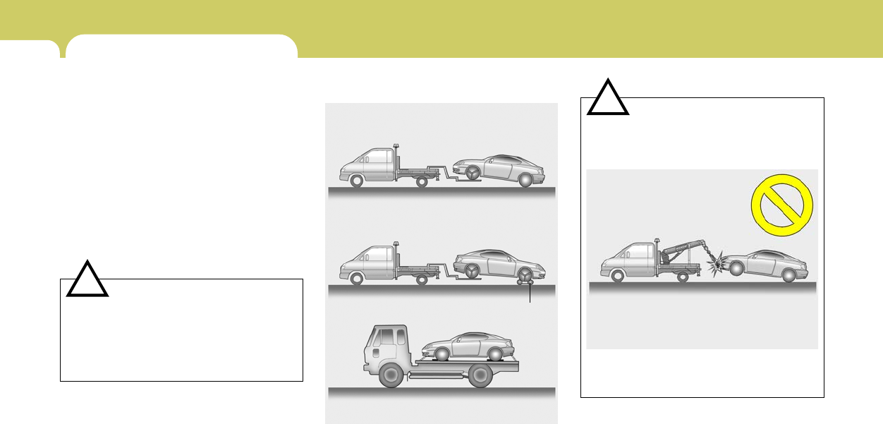
3
12
WHAT TO DO IN AN EMERGENCY
D080B01O-GAT
Towing the Vehicle
HGK4030
Your vehicle can be towed by wheel lift type
truck (1), (2) or flatbed equipment (3).
1)
2)
3) dolly
!
HGK4016
CAUTION:
o When towing the vehicle, take care not to
cause damage to the bumper or under-
body of the vehicle.
o Do not tow with sling type truck as this
may cause damage to the bumper or
underbody of the vehicle.
IF YOUR VEHICLE MUST BE
TOWED
D080A01O-GAT
If your vehicle has to be towed, it should be done
by your Hyundai dealer or a commercial tow
truck service. This will help assure that your
vehicle is not damaged in towing. Also, profes-
sionals are generally aware of local laws gov-
erning towing. In any case, rather than risk
damage to your car, it is suggested that you
show this information to the tow truck operator.
Be sure that a safety chain system is used and
that all local laws are observed.
It is recommended that your vehicle be towed
with a wheel lift and dollies or flatbed equipment
with all the wheels off the ground.
!CAUTION:
o Your vehicle can be damaged if towed
incorrectly!
o Be sure the transaxle is in neutral.
o When the engine will not start, be sure
the steering is unlocked by placing the
key in the "ACC" position.
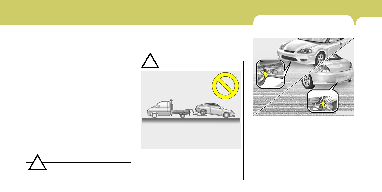
3
WHAT TO DO IN AN EMERGENCY
13
!
1) If the vehicle is being towed with the rear
wheels on the ground, be sure the parking
brake is released.
NOTE:
Before towing, check the level of the auto-
matic transaxle fluid. If it is below the "HOT"
range on the dipstick, add fluid. If you
cannot add fluid, a towing dolly must be
used.
2) If any of the loaded wheels or suspension
components are damaged or the vehicle is
being towed with the front wheels on the
ground, use a towing dolly under the front
wheels.
o Manual Transaxle:
If you do not use a towing dolly, place the
ignition key in the "ACC" position and put the
transaxle in "N (Neutral)". HGK4017
CAUTION:
A vehicle with an automatic transaxle should
never be towed from the rear with the front
wheels on the ground. This can cause se-
rious damage to the transaxle. Be sure to
use a towing dolly under the front wheels.
EMERGENCY TOWING
D080D02A-AAT
For emergency towing when no commercial
tow vehicle is available, attach a tow cable,
chain or strap to one of the towing hooks under
the front /rear of your car. Do not attempt to tow
your vehicle in this manner on any unpaved
surface. This could result in serious damage to
your car.
Nor should towing be attempted if the wheels,
drive train, axles, steering or brakes are dam-
aged. Before towing, be sure the transaxle is in
neutral and the key is in "ACC" (with the engine
off) or in the "ON" position (with the engine
running). A driver must be in the towed car to
steer it and operate the brakes.
HGK4018
Front
Rear
CAUTION:
Do not tow with the key removed or in the
"LOCK" position when towing from the
rear without a towing dolly.
!
o Automatic Transaxle:
Be sure to use a towing dolly under the front
wheels.
3) It is recommended that your vehicle be
towed with all the wheels off the ground.

3
14
WHAT TO DO IN AN EMERGENCY
IF YOU LOSE YOUR KEYS
D120A01A-AAT
If you lose your keys, many Hyundai dealers
can make you a new key if you have your key
number.
If you lock the keys inside your car and you
cannot obtain a new key, many Hyundai dealers
can use special tools to open the door for you.
!CAUTION:
o If the car is being towed with all four
wheels on the ground, it can be towed
only from the front. Be sure that the
transaxle is in neutral. Do not tow at
speeds greater than 30 mph (50 km/h)
and for more than 15 miles (25 km).
o Be sure the steering is unlocked by plac-
ing the key in the "ACC" position. A
driver must be in the towed vehicle to
operate the steering and brakes.

CORROSION PREVENTION & APPEARANCE CARE
4
Corrosion Protection ..................................................... 4-2
To Help Prevent Corrosion ........................................... 4-2
Washing and Waxing .................................................... 4-3
Cleaning the Interior ...................................................... 4-5
4

4CORROSION PREVENTION AND APPEARANCE CARE
2CORROSION PROTECTION
E020B01A-AAT
Keep Your Car Clean
The best way to prevent corrosion is to keep
your car clean and free of corrosive materials.
Attention to the underside of the car is particu-
larly important.
o If you live in a high-corrosion area — where
road salts are used, near the ocean, areas
with industrial pollution, acid rain, etc.—, you
should take extra care to prevent corrosion.
In winter, hose off the underside of your car
at least once a month and be sure to clean
the underside thoroughly when winter is
over.
o When cleaning underneath the car, give
particular attention to the components under
the fenders and other areas that are hidden
from view. Do a thorough job; just dampening
the accumulated mud rather than washing it
away will accelerate corrosion rather than
prevent it. Water under high pressure and
steam are particularly effective in removing
accumulated mud and corrosive materials.
E020A01A-AAT
You can help prevent corrosion from getting
started by observing the following:
E010D01A-AAT
Moisture Breeds Corrosion
Moisture creates the conditions in which corro-
sion is most likely to occur. For example, cor-
rosion is accelerated by high humidity, particu-
larly when temperatures are just above freez-
ing. In such conditions, the corrosive material is
kept in contact with the car surfaces by mois-
ture that is slow to evaporate.
Mud is particularly corrosive because it is slow
to dry and holds moisture in contact with the
vehicle. Although the mud appears to be dry, it
can still retain the moisture and promote corro-
sion.
High temperatures can also accelerate corro-
sion of parts that are not properly ventilated so
the moisture can be dispersed. For all these
reasons, it is particularly important to keep your
car clean and free of mud or accumulations of
other materials. This applies not only to the
visible surfaces but particularly to the underside
of the car.
E010C01A-AAT
High-Corrosion Areas
If you live in an area where your car is regularly
exposed to corrosive materials, corrosion pro-
tection is particularly important. Some of the
common causes of accelerated corrosion are
road salts, dust control chemicals, ocean air
and industrial pollution.
E010B01A-AAT
Common Causes of Corrosion
The most common causes of corrosion on your
car are:
o Road salt, dirt and moisture that is allowed to
accumulate underneath the car.
o Removal of paint or protective coatings by
stones, gravel, abrasion or minor scrapes
and dents which leave unprotected metal
exposed to corrosion.
E010A01A-AAT
Protecting Your Hyundai from
Corrosion
By using the most advanced design and con-
struction practices to combat corrosion,
Hyundai produces cars of the highest quality,
However, this is only part of the job. To achieve
the long-term corrosion resistance your
Hyundai can deliver, the owner’s cooperation
and assistance is also required.
TO HELP PREVENT CORROSION

4
CORROSION PREVENTION AND APPEARANCE CARE
3
WASHING AND WAXING
E020E01A-AAT
Don’t Neglect the Interior
Moisture can collect under the floor mats and
carpeting to cause corrosion. Check under the
mats periodically to be sure the carpeting is dry.
Use particular care if you carry fertilizers, clean-
ing materials or chemicals in the car.
These should be carried only in proper contain-
ers and any spills or leaks should be cleaned up,
flushed with clear water and thoroughly dried.
E020C01A-AAT
Keep Your Garage Dry
Don’t park your car in a damp, poorly ventilated
garage. This creates a favorable environment
for corrosion. This is particularly true if you
wash your car in the garage or drive it into the
garage when it is still wet or covered with snow,
ice or mud. Even a heated garage can contrib-
ute to corrosion unless it is well ventilated so
moisture is dispersed.
E030A01GK-AAT
Washing Your Hyundai
Never wash your car when the surface is hot
from being in the sun. Always wash your car in
the shade.
Wash your car frequently. Dirt is abrasive and
can scratch the paint if it is not removed. Air
pollution or acid rain may damage the paint and
trim through chemical action if pollutants are
allowed to remain in contact with the surface. If
you live near the ocean or in an area where road
salts or dust control chemicals are used, you
should pay particular attention to the underside
of the car. Start by rinsing the car to remove dust
and loose dirt. In winter, or if you have driven
through mud or muddy water, be sure to thor-
oughly clean the underside as well. Use a hard
direct stream of water to remove accumulations
of mud or corrosive materials. High pressure
car washes may cause water to enter your
vehicle. Use a good quality car-washing solu-
tion and follow the manufacturer's directions on
the package. These are available at your
Hyundai dealer or auto parts outlet. Don't use
strong household detergents, gasoline, strong
solvents or abrasive cleaning powders as these
may damage the finish.
Use a clean sponge or cloth, rinse it frequently
and don't damage the finish by rubbing too hard.
For stubborn spots, dampen them frequently
and remove them a little at a time.
o When cleaning lower door panels, rocker
panels and frame members, be sure that
drain holes are kept open so that moisture
can escape and not be trapped inside to ac-
celerate corrosion.
E020D02A-AAT
Keep Paint and Trim in Good Condition
Scratches or chips in the finish should be
covered with "touch-up" paint as soon as pos-
sible to reduce the possibility of corrosion. If
bare metal is showing through, the attention of
a qualified body and paint shop is recommended.
Bird droppings : Bird droppings are highly cor-
rosive and may damage painted surfaces in just
a few hours. Always remove bird droppings as
soon as possible.

4CORROSION PREVENTION AND APPEARANCE CARE
4
E030D01A-AAT
When to Wax Again
You should polish and wax the car again when
water no longer beads on a clean surface but
spreads out over a larger area.
E030C01A-AAT
Polishing and Waxing
Always wash and dry the car before polishing
or waxing or using a combination cleaner and
wax. Use a good quality commercial product
and follow the manufacturer’s directions on the
container. Polish and wax the bright trim pieces
as well as the paint.
E030B01A-AAT
Spot Cleaning
Don’t use gasoline, strong solvents or corro-
sive cleaning agents. These can damage the
finish of the car. To remove road tar, use
turpentine on a clean, soft cloth or commercially
available bug and tar remover. Be gentle.
To remove dead insects or tree sap, use warm
water and mild soap or car-washing solution.
Soak the spot and rub gently. If the paint has lost
its luster, use a commercial car-cleaning polish.
If you find any nicks or scratches in the paint,
use touch-up paint to cover them to prevent
corrosion. To protect the paintwork of the car
against corrosion, you must clean your Hyundai
(at least once a month). Give special attention
to the removal of salt, mud and other sub-
stances on the underside of the splashboards
of the car. Make sure that the outlets and the
underside of the doors are open. Paint damage
can be caused by small accumulation of tar,
industrial precipitation, tree resin, insects and
bird droppings, when not removed immediately.
If water alone is not strong enough to remove the
accumulated dirt, use a mild car washing solu-
tion. Be sure to rinse the surface after washing
to remove the solution. Never allow the solution
to dry on the painted surfaces.
To clean whitewall tires, use a stiff brush or
soapy steel-wool scouring pad.
To clean plastic wheel covers, use a clean
sponge or soft cloth and water.
To clean cast aluminum alloy wheels, use a mild
soap or neutral detergent. Do not use abrasive
cleaners. Protect the bare-metal surfaces by
cleaning, polishing and waxing. Because alumi-
num is subject to corrosion, be sure to give
aluminum alloy wheels special attention in win-
ter. If you drive on salted roads, clean the
wheels thoroughly afterwards.
After washing, be sure to rinse thoroughly. If
soapy water dries on the finish, streaking will
result.
When the weather is warm and the humidity low,
you may find it necessary to rinse each section
immediately after washing to avoid streaking.
After rinsing, dry the car using a damp chamois
or soft, absorbent cloth. The reason for drying
the car is to remove water from the car so it will
dry without water spots. Don't rub, this can
damage the finish.

4
CORROSION PREVENTION AND APPEARANCE CARE
5
CLEANING THE INTERIOR
E040B01A-AAT
To Clean the Leather Upholstery
(If Installed)
In the normal course of use, leather upholstered
surfaces will, like any material, pick-up dust and
dirt. This dust and dirt must be cleaned
off or it may work into the surface of the leather,
causing damage.
Fine leather needs care, and should be cleaned
when necessary. Washing leather thoroughly
with soap and water will keep your leather
lustrous, beautiful and ensure you have many
years of wear.
Take a piece of cheese cloth and using any mild
soap and lukewarm water, work up a good
lather. Thoroughly wash the leather. Wipe clean
with a slightly damp cloth and dry with soft cloth.
Do this as often as the leather becomes soiled.
During tanning operations, sufficient oils are
incorporated through processing that none need
be applied during the life of the leather. Oil
applied to the finished surface will in no way help
the leather and may do more harm than good.
Varnishes and furniture polishes should never
be used under any conditions.
E040A01A-AAT
To Clean the Vinyl Upholstery
To clean the vinyl upholstery, first remove loose
dirt and dust with a vacuum cleaner. Then apply
a solution of mild soap or detergent and water
using a clean sponge or soft cloth. Allow this to
stay on the surface to loosen the dirt, then wipe
with a clean damp sponge or cloth. If all the dirt
stains are not removed, repeat this procedure
until the upholstery is clean. Do not use gaso-
line, solvent, paint thinner or other strong clean-
ers.
E030E01A-AAT
Maintaining Bumpers
Special precautions must be observed to pre-
serve the appearance of the bumpers on your
Hyundai. They are:
o Be careful not to spill battery electrolyte or
hydraulic brake fluid on the bumpers. If you
do, wash it off immediately with clear water.
o Be gentle when cleaning the bumper sur-
faces. They are made of soft plastic and the
surface can be damaged if mistreated. Do
not use abrasive cleaners. Use warm water
and mild soap or car-washing solution.
o Do not expose the bumpers to high tem-
peratures. For example, if you have your car
repainted, do not leave the bumpers on the
car if the car is going to be placed in a high-
temperature paint booth.

4CORROSION PREVENTION AND APPEARANCE CARE
6ANY QUESTIONS?
E040D01A-AAT
Cleaning the Seat Belts
To clean the seat belts, use a cloth or sponge
with mild soap or detergent and warm water. Do
not use strong detergents, dye, bleach or abra-
sive materials on the seat belts as this may
weaken the fabric.
While cleaning the belts, inspect them for ex-
cessive wear, cuts, fraying or other signs of
damage and replace them if necessary.
E040C01A-AAT
Cleaning the Carpets
Use a foam-type carpet cleaner. Cleaners of
this type are available in aerosol cans in liquid
form or powder. Read the instructions and
follow them exactly. Using a vacuum cleaner
with the appropriate attachment, remove as
much dirt from the carpets as possible. Apply
the foam following the manufacturer’s direc-
tions, then rub in overlapping circles. Do not add
water. These cleaners work best when the
carpet is kept as dry as possible.
E050A01A-AAT
If you have any questions about the care of your
car, consult your Hyundai dealer.
E040E01A-AAT
Cleaning the Windows
You may use any household window cleaner on
the windows. However, when cleaning the in-
side of the rear window be careful not to damage
the rear window defroster wiring.

VEHICLE MAINTENANCE REQUIREMENTS
5
Maintenance Intervals ................................................... 5-2
Scheduled Maintenance ................................................ 5-4
Maintenance under Severe Usage Conditions ............. 5-6
Explanation of Scheduled Maintenance Items .............. 5-7
5

5VEHICLE MAINTENANCE REQUIREMENTS
2
F010D01A-AAT
General Checks
These are the regular checks you should per-
form when you drive your Hyundai or you fill the
fuel tank. A list of these items will be found on
page 6-4.
F010C01A-AAT
Specified Scheduled Procedures
These are the procedures such as inspections,
adjustments and replacements that are listed in
the maintenance charts starting on page 5-4.
These procedures must be performed at the
intervals shown in the maintenance schedule to
assure that your warranty remains in effect.
Although it is strongly recommended that they
be performed by the trained technicians at your
Hyundai dealer, these procedures may be per-
formed at any qualified service facility.
It is suggested that genuine Hyundai service
parts be used for any required repairs or re-
placements. Other parts of equivalent quality
such as engine oil, engine coolant, manual or
auto transaxle oil, brake fluid and so on which
are not supplied by Hyundai Motor Company or
its distributor may be used without affecting
your warranty coverage but you should always
be sure these are equivalent to the quality of the
original Hyundai parts. Your Owner's Hand-
book provides further information about your
warranty coverage.
F010A01A-AAT
Service Requirements
To ensure that you receive the greatest number
of miles of satisfying operation from your Hyundai,
certain maintenance procedures must be per-
formed. Although careful design and engineer-
ing have reduced these to a minimum, those that
are required are of the utmost importance.
It is your responsibility to have these mainte-
nance procedures performed to comply with
the terms of the warranties covering your new
Hyundai. The Owner's Handbook supplied with
your new vehicle provides further information
about these warranties.
F010B01A-AAT
Maintenance Requirements
The maintenance required for your Hyundai
can be divided into three main areas:
o Specified scheduled procedures
o General checks
o Do-it-yourself maintenance
F010E01A-AAT
Do-It-Yourself Maintenance
If you are mechanically inclined, own a few tools
that are required and want to take the time to do
so, you can inspect and service a number of
items. For more information about doing it your-
self, see Section 6.
MAINTENANCE INTERVALS

5
VEHICLE MAINTENANCE REQUIREMENTS
3
SCHEDULED MAINTENANCE
REQUIREMENTS
F020A02S-AAT
o Inspection should be performed any time a
malfunction is experienced or suspected.
o Receipts for all emission control system
services should be retained to demonstrate
compliance with conditions of the emissions
system warranty.
o After 120 months or 150,000 miles (240,000
km), continue to follow the prescribed main-
tenance intervals.
o For severe usage maintenance require-
ments, see page 5-6 of this section.
F010F01A-AAT
A Few Tips
o Whenever you have your Hyundai serviced,
keep copies of the service records in your
glovebox. This will help ensure that you can
document that the required procedures have
been performed to keep your warranties in
effect. This is especially important when
service is not performed by an authorized
Hyundai dealer.
o If you choose to do your own maintenance
and repairs, you may find it helpful to have
an official Hyundai Shop Manual. A copy of
this publication may be purchased at your
Hyundai dealer's parts department.

5VEHICLE MAINTENANCE REQUIREMENTS
4SCHEDULED MAINTENANCE
F030B04GK-AAT
R :Replace I : Inspect and, after inspection, clean, adjust, repair or replace if necessary.
DESCRIPTION
EMISSION CONTROL ITEMS
ENGINE OIL AND FILTER
FUEL FILTER
FUEL LINES, FUEL HOSES AND CONNECTIONS
CRANKCASE VENTILATION HOSES
VAPOR HOSE AND FUEL FILLER CAP
AIR CLEANER FILTER
SPARK PLUGS (PLATINUM COATED)
SPARK PLUGS (IRIDIUM COATED)
VALVE CLEARENCE (2.0 L)
FUEL TANK AIRFILTER
No.
1
2
3
4
5
6
7
8
9
MILES X 1000
KILOMETERS X 1000
MONTHS
7.5
12
6
R
I
15
24
12
R
I
I
22.5
36
18
R
I
30
48
24
R
I
I
R
R
37.5
60
30
R
R
I
45
72
36
R
I
I
52.5
84
42
R
I
I
60
96
48
R
I
I
R
R
I
R
67.5
108
54
R
I
75
120
60
R
R
I
I
82.5
132
66
R
I
90
144
72
R
I
I
R
R
97.5
156
78
R
I
R
105
168
84
R
I
I
I
112.5
180
90
R
R
I
120
192
96
R
I
I
R
R
I
R
127.5
204
102
R
I
135
216
108
R
I
I
142.5
228
114
R
I
150
240
120
R
R
I
I
R
R
F030A01A-AAT
The following maintenance services must be performed to ensure good emission control and performance. Keep receipts for all vehicle emission services
to protect your emission warranty. Where both mileage and time are shown, the frequency of service is determined by whichever occurs first.

5
VEHICLE MAINTENANCE REQUIREMENTS
5
Note :
*1 - FOR EVERY 12 MONTHS OR 10,000 MILES (15,000 KM), WHICHEVER OCCURS FIRST : "R"
F030C02GK-AAT
R : Replace I : Inspect and, after inspection, clean, adjust, repair or replace if necessary
No.
1
2
3
4
5
6
7
8
9
10
11
12
13
14
15
16
DESCRIPTION
GENERAL ITEMS
DRIVE BELT (WATER PUMP, GENERATOR AND A/CON)
COOLANT
TIMING BELT
MANUAL TRANSAXLE OIL
AUTOMATIC TRANSAXLE FLUID
BRAKE FLUID & CLUTCH FLUID
BRAKE HOSES AND LINES
REAR BRAKE DRUMS/LININGS, PARKING BRAKE
BRAKE PADS, CALIPERS AND ROTORS
EXHAUST PIPE AND MUFFLER
SUSPENSION MOUNTING BOLTS
STEERING GEAR BOX, LINKAGE & BOOTS/LOWER ARM
BALL JOINT
POWER STEERING PUMP, BELT AND HOSES
DRIVESHAFTS AND BOOTS
AIR CONDITIONING REFRIGERANT
AIR CONDITIONER FILTER (FOR BLOWER UNIT)
MILES X 1000
KILOMETERS X 1000
MONTHS
7.5
12
6
I
15
24
12
I
I
I
I
I
I
I
I
22.5
36
18
I
30
48
24
I
R
I
I
I
I
I
I
I
I
I
I
I
I
I
37.5
60
30
I
45
72
36
I
I
I
I
I
I
I
I
52.5
84
42
I
60
96
48
I
R
R
I
I
I
I
I
I
I
I
I
I
I
I
67.5
108
54
I
75
120
60
I
I
I
I
I
I
I
I
82.5
132
66
I
90
144
72
I
R
I
I
I
I
I
I
I
I
I
I
I
I
I
97.5
156
78
I
105
168
84
R
I
I
I
I
I
I
I
112.5
180
90
I
120
192
96
I
R
R
I
I
I
I
I
I
I
I
I
I
I
I
127.5
204
102
I
135
216
108
I
I
I
I
I
I
I
I
142.5
228
114
I
150
240
120
I
R
I
I
I
I
I
I
I
I
I
I
I
I
I
SEE NOTE *1

5VEHICLE MAINTENANCE REQUIREMENTS
6MAINTENANCE UNDER SEVERE USAGE CONDITIONS
F040A04GK-AAT
The following items must be serviced more frequently on cars normally used under severe driving conditions. Refer to the chart below for the appropriate
maintenance intervals.
R : Replace I : Inspect and, after inspection, clean, adjust, repair or replace if necessary
ENGINE OIL AND FILTER
TIMING BELT
AIR CLEANER FILTER
SPARK PLUGS
BRAKE PADS, CALIPERS AND ROTORS
REAR BRAKE DRUMS/LININGS/PADS,
PARKING BRAKE
STEERING GEAR BOX, LINKAGE & BOOTS/
LOWER ARM BALL JOINT
DRIVESHAFTS AND BOOTS
MANUAL TRANSAXLE OIL
AUTOMATIC TRANSAXLE FLUID
AIR CONDITIONER FILTER (FOR BLOWER UNIT)
MAINTENANCE ITEM
R
R
R
R
I
I
I
I
R
R
R
EVERY 3,000 MILES (4,800 KM) OR 3 MONTHS
EVERY 40,000 MILES (64,000 KM) OR 48 MONTHS
MORE FREQUENTLY
MORE FREQUENTLY
MORE FREQUENTLY
MORE FREQUENTLY
MORE FREQUENTLY
EVERY 7,500 MILES (12,000 KM) OR 6 MONTHS
EVERY 60,000 MILES (96,000 KM)
EVERY 30,000 MILES (48,000 KM)
MORE FREQUENTLY
DRIVING
CONDITION
MAINTENANCE
INTERVALS
MAINTENANCE
OPERATION
A, B, C, D, E, F, G, H, I, K
B, C, D, E, F, G
C, E
B, H
C, D, G, H
C, D, G, H
C, D, E, F, G
C, D, E, F, G
A, C, D, E, F, G, H, I, J
A, C, E, F, G, H, I
C, E
SEVERE DRIVING CONDITIONS
A - Repeatly driving short distance of less than 5miles(8km) in normal tempera
ture or less than 10miles(16km) in freezing temperature
B - Extensive engine idling or low speed driving for long distances
C - Driving on rough, dusty, muddy, unpaved, graveled or salt-spread roads
D - Driving in areas using salt or other corrosive materials or in very cold
weather
E - Driving in sandy areas
F - Driving in heavy traffic area over 90°F(32°C)
G - Driving on uphill, downhill, or mountain road
H - Towing a Trailer, or using a camper, or roof rack
I - Driving as a patrol car, taxi, other commercial use or vehicle towing
J - Driving over 100 MPH(170 Km/h)
K - Frequently driving in stop-and-go conditions

5
VEHICLE MAINTENANCE REQUIREMENTS
7
F060D01A-AAT
o Fuel Lines, Fuel Hoses and
Connections
Check the fuel lines, fuel hoses and connec-
tions for leakage and damage. Have a trained
technician replace any damaged or leaking
parts immediately.
F060M01A-AAT
o Engine Oil and Filter
The engine oil and filter should be changed at the
intervals specified in the maintenance sched-
ule. If the car is being driven in severe condi-
tions, more frequent oil and filter changes are
required.
F060C01A-AAT
o Fuel Filter
A clogged filter can limit the speed at which the
vehicle may be driven, damage the emission
system and cause hard starting. If an exces-
sive amount of foreign matter accumulates in
the fuel tank, the filter may require replacement
more frequently.
After installing a new filter, run the engine for
several minutes, and check for leaks at the
connections. Fuel filters should be installed by
trained technicians.
F060F02A-AAT
o Crankcase Ventilation Hoses
Inspect the surface of hoses for evidence of
heat and/or mechanical damage. Hard and
brittle rubber, cracking, tears, cuts, abrasions,
and excessive swelling indicate deterioration.
Particular attention should be paid to examine
those hose surfaces nearest to high heat
sources, such as the exhaust manifold.
Inspect the hose routing to assure that the
hoses do not come in contact with any heat
source, sharp edges or moving component
which might cause heat damage or mechanical
wear. Inspect all hose connections, such as
clamps and couplings, to make sure they are
secure, and that no leaks are present. Hoses
should be replaced immediately if there is any
evidence of deterioration or damage.
EXPLANATION OF SCHEDULED MAINTENANCE ITEMS
F060H01A-AAT
o Air cleaner filter
A Genuine Hyundai air cleaner filter is recom-
mended when the filter is replaced.
F060G01A-AAT
o Vapor Hose and Fuel Filler Cap
The vapor hose and fuel filler cap should be
inspected at those intervals specified in the
maintenance schedule. Make sure that a new
vapor hose or fuel filler cap is correctly re-
placed.
F060J01A-AAT
o Spark plugs
Make sure to install new spark plugs of the
correct heat range.
F060N02E-AAT
o Valve Clearance (2.0L)
Inspect excessive valve noise and/or engine
vibration and adjust if necessary. A qualified
technician should perform the operation.

5VEHICLE MAINTENANCE REQUIREMENTS
8
F060B02A-AAT
o Drive Belts
Inspect all drive belts for evidence of cuts,
cracks, excessive wear or oil saturation and
replace if necessary. Drive belts should be
checked periodically for proper tension and
adjusted as necessary.
F070C01A-AAT
o Coolant
The coolant should be changed at the intervals
specified in the maintenance schedule.
F060E01A-AAT
o Timing belt
Inspect all parts related to the timing belt for
damage and deformation. Replace any dam-
aged parts immediately.
F070D01A-AAT
o Manual transaxle oil
Inspect the manual transaxle oil according to
the maintenance schedule.
NOTE:
If the oil level is low, check for possible leaks
before adding oil. Do not overfill.
F070G03A-AAT
o Brake Fluid & Clutch Fluid
Check brake fluid level in the brake fluid reser-
voir. The level should be between "MIN" and
"MAX" marks on the side of the reservoir. Use
only hydraulic brake fluid conforming to DOT 3
or DOT 4.
F070H01A-AAT
o Rear Brake Drums and Linings/
Parking Brake
Check the rear brake drums and linings for
scoring, burning, leaking fluid, broken parts,
and excessive wear. Inspect the parking brake
system including the parking brake lever and
cables. For detailed service procedures, refer
to the Shop Manual.
F070F01A-AAT
o Brake Hoses and Lines
Visually check for proper installation, chafing,
cracks, deterioration and any leakage. Replace
any deteriorated or damaged parts immedi-
ately.
F070E06A-AAT
o Automatic Transaxle Fluid
The fluid level should be in the “HOT” range of
the dipstick, after the engine and transaxle are
at normal operating temperature. Check the
automatic transaxle fluid level with the engine
running and the transaxle in neutral, with the
parking brake properly applied. Use HYUNDAI
GENUINE ATF SP III, DIAMOND ATF SP III, SK
ATF SP III or other brands meeting the SP III
specification approved by Hyundai Motor Co.
when adding or changing fluid. Using the wrong
ATF may result in damage to the ATM.

5
VEHICLE MAINTENANCE REQUIREMENTS
9
F070J01A-AAT
o Brake Pads, Calipers and Rotors
Check the pads for excessive wear, discs for
run out and wear, and calipers for fluid leakage.
F070K01A-AAT
o Exhaust Pipe and Muffler
Visually inspect the exhaust pipes, muffler and
hangers for cracks, deterioration, or damage.
Start the engine and listen carefully for any
exhaust gas leakage. Tighten connections or
replace parts as necessary.
F070L01A-AAT
o Suspension Mounting Bolts
Check the suspension connections for loose-
ness or damage. Retighten to the specified
torque.
F070M01A-AAT
o Steering gear box, linkage &
boots/lower arm ball joint
With the vehicle stopped and engine off, check
for excessive free-play in the steering wheel.
Check the linkage for bends or damage. Check
the dust boots and ball joints for deterioration,
cracks, or damage. Replace any damaged
parts.
F070N01A-AAT
o Power Steering Pump, Belt and Hoses
Check the power steering pump and hoses for
leakage and damage. Replace any damaged or
leaking parts immediately. Inspect the power
steering belt for evidence of cuts, cracks, ex-
cessive wear, oiliness and proper tension.
Replace or adjust it if necessary.
F070P01A-AAT
o Drive Shafts and Boots
Check the drive shafts, boots and clamps for
cracks, deterioration, or damage. Replace any
damaged parts and, if necessary, repack the
grease.
F070Q01A-AAT
o Air Conditioning Refrigerant
Check the air conditioning lines and connec-
tions for leakage and damage. Check air con-
ditioning performance according to the relevant
shop manual if necessary.

Do-It-Yourself Maintenance
6
Engine Compartment .................................................... 6-2
General Checks ............................................................ 6-4
Checking the Engine Oil ............................................... 6-5
Changing the Oil and Filter ............................................ 6-6
Checking and Changing the Engine Coolant ................ 6-7
Changing the Air Cleaner Filter ................................... 6-10
Checking the Transaxle Oil (manual) ......................... 6-12
Checking the Transaxle Fluid (Automatic) .................. 6-13
Checking the Brakes .................................................. 6-15
Checking the Clutch Fluid ........................................... 6-16
Air Conditioning Care .................................................. 6-17
Checking Drive Belts .................................................. 6-21
Checking and Replacing Fuses .................................. 6-22
Checking the Battery .................................................. 6-23
Power Steering Fluid Level ......................................... 6-26
Headlight Aiming Adjustment ...................................... 6-26
Replacement of Light Bulbs ........................................ 6-28
Bulb Wattage............................................................... 6-37
Fuse Panel Description ............................................... 6-38
6
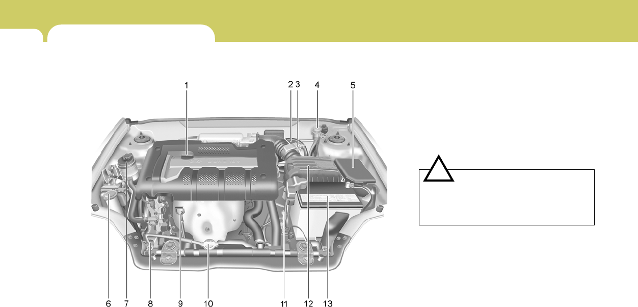
6DO-IT-YOURSELF MAINTENANCE
2ENGINE COMPARTMENT
G010B01GK-GAT
(2.0 DOHC CVVT)
HGK5002
1. Engine oil filler cap
2. Brake booster
3. Brake fluid reservoir
4. Clutch fluid reservoir (If installed)
5. Relay box
6. Windshield washer fluid reservoir cap
7. Power steering fluid reservoir
8. Engine coolant reservoir
9. Engine oil level dipstick
10.Radiator cap
11.Automatic transaxle fluid level dipstick
(If installed)
12.Air cleaner
13.Battery
CAUTION:
When inspecting or servicing the engine,
you should handle tools and other heavy
objects carefully so that the plastic rocker
cover of the engine is not damaged.
!
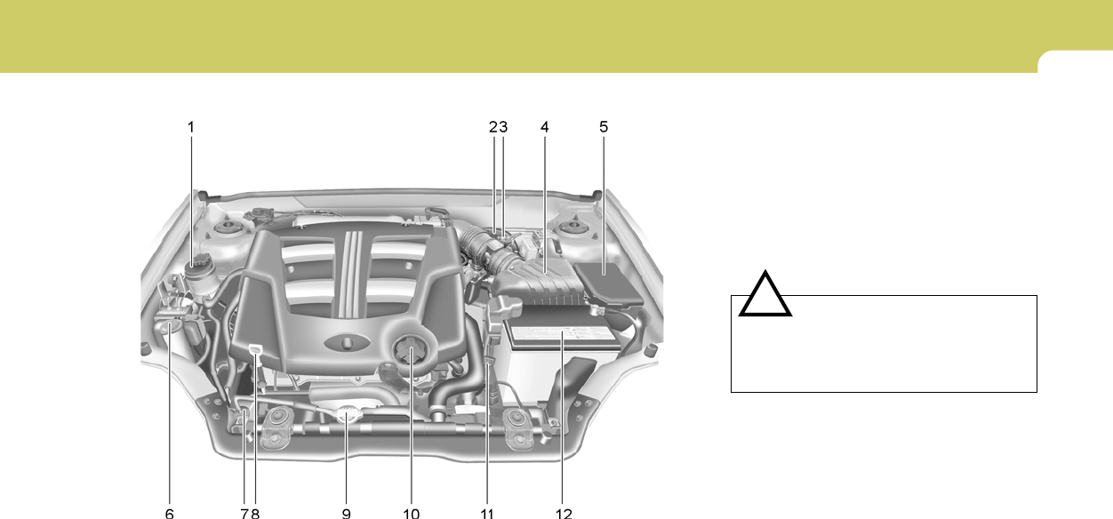
6
DO-IT-YOURSELF MAINTENANCE
3
G010C01GK-GAT
(2.7 V6)
HGK5001
1. Power steering fluid reservoir
2. Brake booster
3. Brake fluid reservoir
4. Air Cleaner
5. Relay box
6. Windshield washer fluid reservoir cap
7. Engine coolant reservoir
8. Engine oil level dipstick
9. Radiator cap
10.Engine oil filler cap
11.Automatic transaxle fluid level dipstick
(If installed)
12.Battery
CAUTION:
When inspecting or servicing the engine,
you should handle tools and other heavy
objects carefully so that the plastic rocker
cover of the engine is not damaged.
!

6DO-IT-YOURSELF MAINTENANCE
4GENERAL CHECKS
G020C01A-AAT
Vehicle Interior
The following should be checked each time
when the vehicle is driven:
o Lights operation
o Windshield wiper operation
o Horn operation
o Defroster, heating system operation (and air
conditioning, if installed)
o Steering operation and condition
o Mirror condition and operation
o Turn signal operation
o Accelerator pedal operation
o Brake operation, including parking brake
o Manual transaxle operation, including clutch
operation
o Automatic transaxle operation, including
"Park" mechanism operation
o Seat control condition and operation
o Seat belt condition and operation
o Sunvisor operation
If you notice anything that does not operate
correctly or appears to be functioning incor-
rectly, inspect it carefully and seek assistance
from your Hyundai dealer if service is needed.
G020B01A-AAT
Vehicle Exterior
The following should be checked monthly:
o Overall appearance and condition
o Wheel condition and wheel nut torque
o Exhaust system condition
o Light condition and operation
o Windshield glass condition
o Wiper blade condition
o Paint condition and body corrosion
o Fluid leaks
o Door and hood lock condition
o Tire pressure and condition (including spare
tire)
G020A01A-AAT
Engine Compartment
The following should be checked regularly:
o Engine oil level and condition
o Transaxle fluid level and condition
o Brake fluid level
o Clutch fluid level
o Engine coolant level
o Windshield washer fluid level
o Accessory drive belt condition
o Engine coolant hose condition
o Fluid leaks (on or below components)
o Power steering fluid level
o Battery condition
o Air filter condition
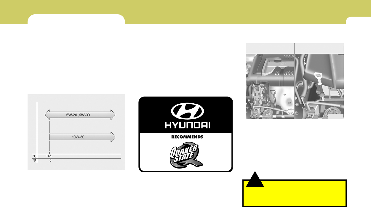
6
DO-IT-YOURSELF MAINTENANCE
5
!
G030C02A-AAT
To Check the Oil Level
HGK5004
2.0L 2.7L
Before checking the oil, warm up the engine to
the normal operating temperature and be sure
your car is parked on level ground. Turn the
engine off.
Wait 5 minutes, then remove the dipstick, wipe
it off, fully reinsert the dipstick and withdraw it
again. Then note the highest level the oil has
reached on the dipstick. It should be between
the upper ("F") and lower ("L") range.
CHECKING THE ENGINE OIL
G030A01A-AAT
Engine oil is essential to the performance and
service of the engine. It is suggested that you
check the oil level at least once a week in normal
use and more often if you are on a trip or driving
in severe conditions.
G030B01O-AAT
Recommended Oil
The engine oil quality should meet the following
classification.
API SJ, SL or ABOVE,
ILSAC GF-3 or ABOVE
G030B01JM-U
NOTE:
o For good fuel economy, SAE 5W-20 (5W-
30), ILSAC GF-3 engine oil is preferred
regardless of regional option and en-
gine variation.
o If SAE 5W-20 (5W-30), ILSAC GF-3 en-
gine oil is not available, secondary rec-
ommended engine oil for correspond-
ing temperature range can be used.
WARNING:
Be very careful not to touch the radiator
hose when adding the engine oil as it may
be hot enough to burn you.
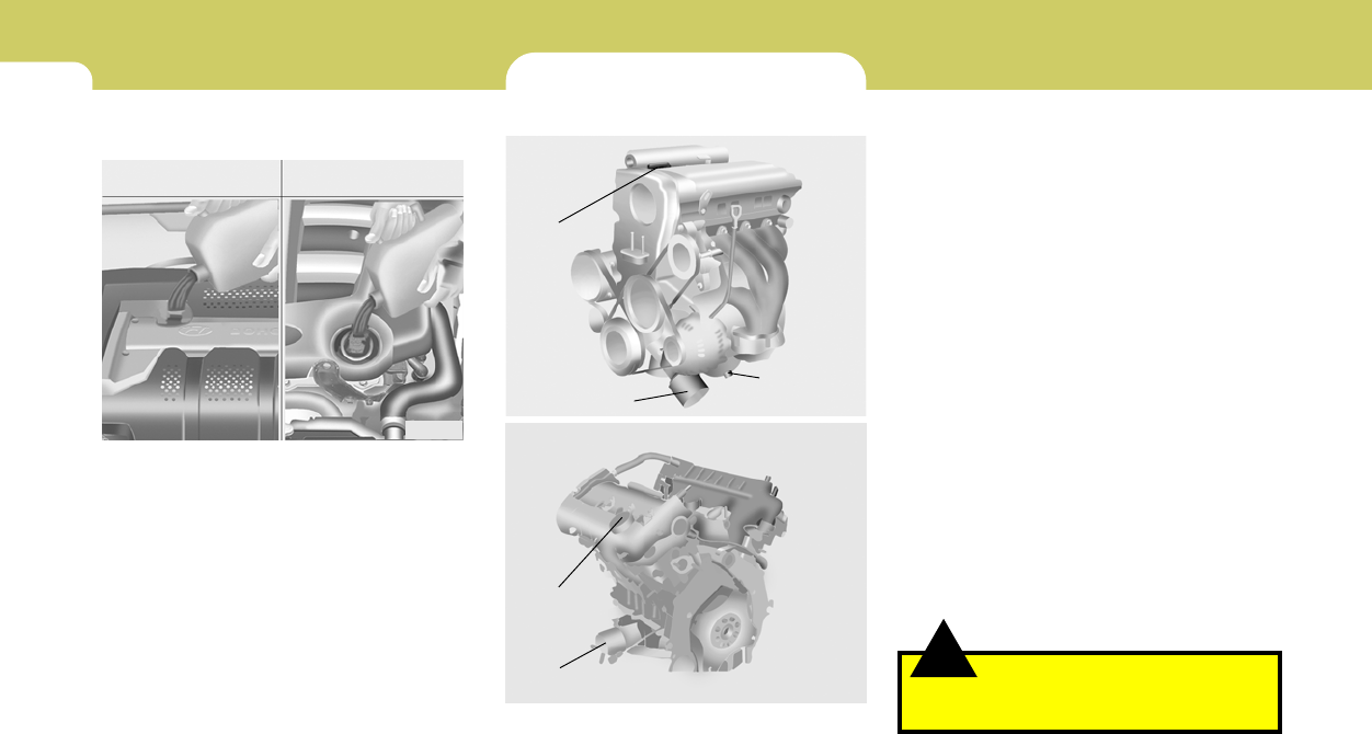
6DO-IT-YOURSELF MAINTENANCE
6CHANGING THE OIL AND FILTER
!
If the oil level is close to or below the "L" mark,
add oil until it reaches the "F" mark. To add oil:
1. Remove the oil filler cap by turning it counter-
clockwise.
2. Add oil, then check the level again. Do not
overfill.
3. Replace the cap by turning it clockwise.
The distance between the "F" and "L" marks is
equal to about 1 quart of oil.
G040A04GK-AAT
2. Open the hood and remove the engine oil
filler cap.
3. Slide underneath the car and loosen the
drain plug by turning it counterclockwise with
a wrench of the proper size. Be sure that a
drain pan is in position to catch the oil as it
drains out, then remove the drain plug.
WARNING:
Be very careful when draining the engine oil
as it may be hot enough to burn you!
G030D01A-AAT
Adding Oil
HGK5005
2.0L 2.7L
The engine oil and filter should be changed at
those intervals specified in the maintenance
schedule in Section 5. If the car is being driven
in severe conditions, more frequent oil and filter
changes are required.
The procedure for changing the oil and filter is
as follows:
1. Park the car on level ground and set the
parking brake. Start the engine and let it
warm up until the needle on the coolant
temperature gauge moves above the lowest
mark. Turn the engine off and place the gear
selector lever in "P" (automatic) or reverse
gear (manual transaxle).
G040A03E
G040A01B
Oil filler cap
Oil filter
2.0L
2.7L
Oil filler cap
Oil filter
Drain plug
6
DO-IT-YOURSELF MAINTENANCE
7
CHECKING AND CHANGING THE
ENGINE COOLANT
!
G050A01A-AAT
WARNING:
Do not remove the radiator cap when the
engine is hot. When the engine is hot, the
engine coolant is under pressure and may
erupt through the opening if the cap is
removed. You could be seriously burned if
you do not observe this precaution. Do not
remove the radiator cap until the radiator is
cool to the touch.
!
!
4. When the oil has stopped draining, replace
the drain plug using a new gasket and re-
tighten by turning it clockwise.
Tightening torque is:
4.5 ~ 4.0 kgf.m (2.0L)
4.5 ~ 3.5 kgf.m (2.7L)
5. Remove the oil filter by turning it counter-
clockwise with a oil filter wrench of the proper
size. A certain amount of oil will come out
when you remove the filter. So be sure to
have your drain pan in place underneath it.
6. Install a new oil filter in accordance with the
instructions on the carton or on the filter itself.
Do not over-tighten. (Tightening torque :
1.2 ~ 1.6 kgf.m)
Be sure that the mounting surface on the
engine is clean and that the old gasket is
removed completely. Lubricate the new
gasket on the filter with clean engine oil
before installation.
7. Remove the engine oil level dipstick.
8. Refill the crankcase with the recommended
engine oil. Refer to the specification in chap-
ter 9 for engine oil capacity.
CAUTION:
Slowly pour the recommended oil using by
a funnel. Do not overfill! Engine damage
may occur if overfilled.
9. Start the engine and check to be sure no oil
is leaking from the drain plug or oil filter.
10.Shut off the engine and recheck the oil level.
NOTE:
Always dispose of used engine oil in an
environmentally acceptable manner. It is
suggested that it be placed in a sealed
container and taken to a service station for
reclamation. Do not pour the oil on the
ground or put it in with the household
trash.
PROPOSITION 65 WARNING:
This product contains a chemical known to
the State of California to cause cancer.
Used engine oil may cause irritation or
cancer of the skin if left in contact with the
skin for prolonged periods of time. Used
engine oil contains chemicals that have
caused cancer in laboratory animals. Al-
ways protect your skin by washing your
hands thoroughly with soap and warm
water as soon as possible after handling
used oil.
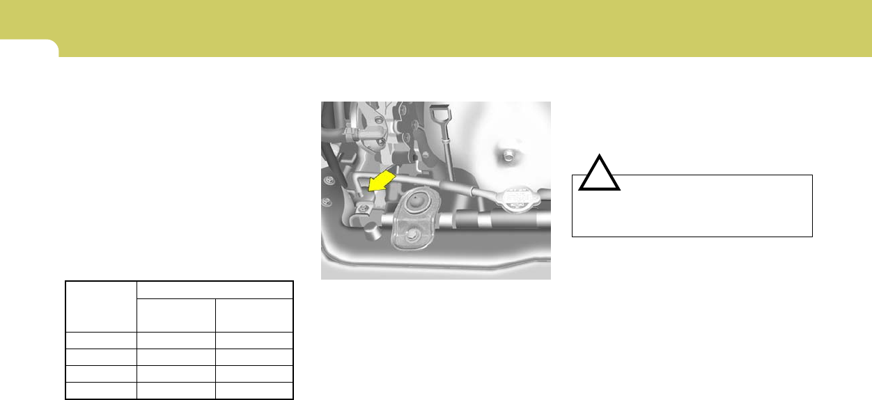
6DO-IT-YOURSELF MAINTENANCE
8
G050C01A-AAT
To Check the Coolant Level
G050D02A-AAT
To Change the Engine Coolant
The engine coolant should be changed at those
intervals specified in the vehicle maintenance
schedule in Section 5.
CAUTION:
Engine coolant can damage the finish of
your car. If you spill engine coolant on the
car, wash it off thoroughly with clean water.
1. Park the car on level ground, set the park-
ing brake and remove the radiator cap when
cool.
2. Be sure your drain receptacle is in place.
Open the drain cock on the radiator. Allow all
the engine coolant to drain from the cooling
system, then securely close the drain cock.
3. Check Section 9 for the capacity of the
cooling system in your car. Then, following
the manufacturer’s directions on the engine
coolant container, add the appropriate quan-
tity of coolant to the radiator.
!
The coolant level can be seen on the side of the
plastic coolant reservoir. The level of the cool-
ant should be between the "L" and "F" lines on
the reservoir when the engine is cold. If the level
is below the "L" mark, add engine coolant to
bring it up between "L" and "F". If the level is low,
inspect for coolant leaks and recheck the fluid
level frequently. If the level drops again, visit
your Hyundai dealer for an inspection and
diagnosis of the reason.
HGK4006
G050B01A-AAT
Recommended Engine Coolant
Use a high quality ethylene-glycol coolant in a
50/50 mix with water. The engine coolant should
be compatible with aluminum engine parts.
Additional corrosion inhibitors or additives should
not be used. The cooling system must be
maintained with the correct concentration and
type of engine coolant to prevent freezing and
corrosion. Never allow the concentration of
antifreeze to exceed the 60% level or go below
the 35% level, or damage to the cooling system
may result. For proper concentration when
adding or replacing the engine coolant, refer to
the following table.
Ambient
temperature
°F ( °G)
5 (-15)
-13 (-25)
-31 (-35)
-49 (-45)
65%
60%
50%
40%
35%
40%
50%
60%
Water
Antifreeze
solution
Engine Coolant concentration
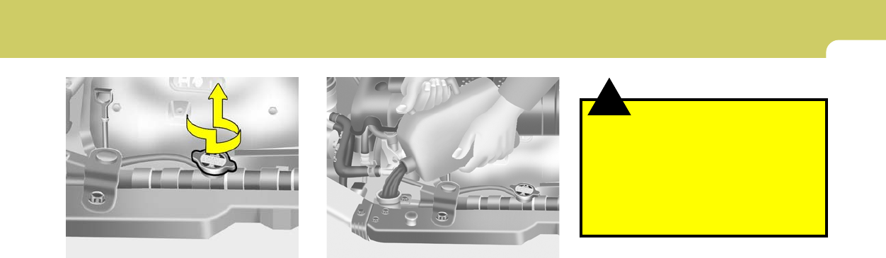
6
DO-IT-YOURSELF MAINTENANCE
9
!WARNING:
The cooling fan is controlled by engine
coolant temperature and may sometimes
operate even when the engine is not run-
ning. Use extreme caution when working
near the blades of the coolant fan so that
you are not injured by a rotating fan blade.
As the engine coolant temperature de-
creases, the fan will automatically shut off.
This is a normal condition.
4. Turn the radiator cap counterclockwise with-
out pressing down on it, until it stops. This
relieves any pressure remaining in the cool-
ing system. And remove the radiator cap by
pushing down and turning counterclock-
wise.
Now fill the radiator with clean demineralized
or distilled water. Continue to add clean
demineralized or distilled water in small quan-
tities until the fluid level stays up in the
radiator neck.
G050D03E
5. Start the engine, top off the radiator with
water and then add coolant to the reservoir
until the level is between "L" and "F".
6. Replace the radiator and reservoir caps and
check to be sure the drain cocks are fully
closed and not leaking.
G050D04E
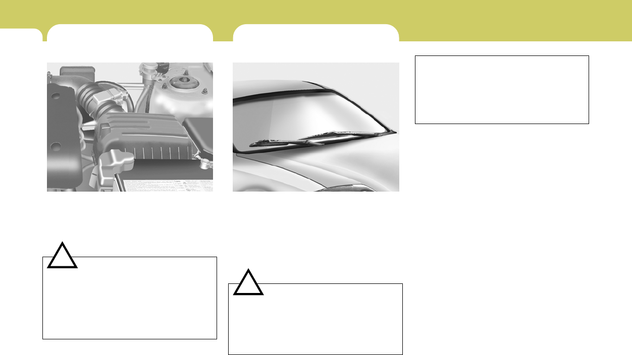
6DO-IT-YOURSELF MAINTENANCE
10 CHANGING THE AIR CLEANER
FILTER
G070A01E-AAT
To change the filter, unsnap the clips around the
cover. When this is done, the cover can be lifted
off, the old filter removed and the new filter put
in its place. Genuine Hyundai Replacement
Parts are recommended.
CAUTION:
o Operating your vehicle without a proper
air filter in place can result in excessive
engine wear.
o When removing the air cleaner filter, be
careful that dust or dirt does not enter
the air intake. These may result in dam-
age to the air cleaner filter.
HGK5010
!
WINDSHIELD WIPER BLADES
G080A03A-AAT
The wiper blades should be carefully inspected
from time to time and cleaned to remove accu-
mulations of road film or other debris. To clean
the wiper blades and arms, use a clean sponge
or cloth with a mild soap or detergent and water.
If the wipers continue to streak or smear the
glass, replace them with Genuine Hyundai
Replacement Parts or their equivalent.
G080A02GK
!CAUTION:
o Do not operate the wipers on dry glass.
This can result in more rapid wear of the
wiper blades and may scratch the glass.
o Keep the blade rubber out of contact
with petroleum products such as engine
oil, gasoline etc.
o When the wiper blade is freezed in winter
or the washer fluid reservoir is empty, the
wiper may not operate for ten minutes.
This isn't a mechanical trouble but the
function protecting the wiper by operat-
ing circuit breaker inside of the wiper
motor.
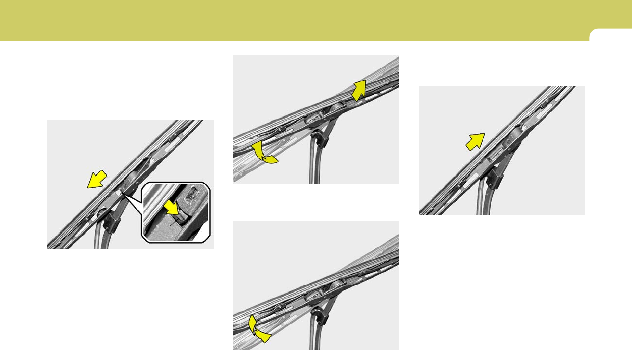
6
DO-IT-YOURSELF MAINTENANCE
11
1. Put a new wiper blade onto the wiper arm and
lower the wiper blade at the level of the wiper
arm as shown in the drawing.
2. Pull up the wiper blade until you hear an
audible "click" to engage in the end of the
wiper arm.
NOTE:
Do not allow the wiper arm to fall against the
windshield.
2. Raise the wiper blade lightly and pull up it.
To install the wiper blade
HHR5049
HHR5050
G080B01HR-GAT
Replacing the Wiper Blades
To replace the wiper blades, raise the wiper to
the vertical.
To remove the wiper blade
1. Push down the wiper blade with the locking clip
(1) pressed to detach it from the wiper arm.
HHR5048
(1)
HHR5051
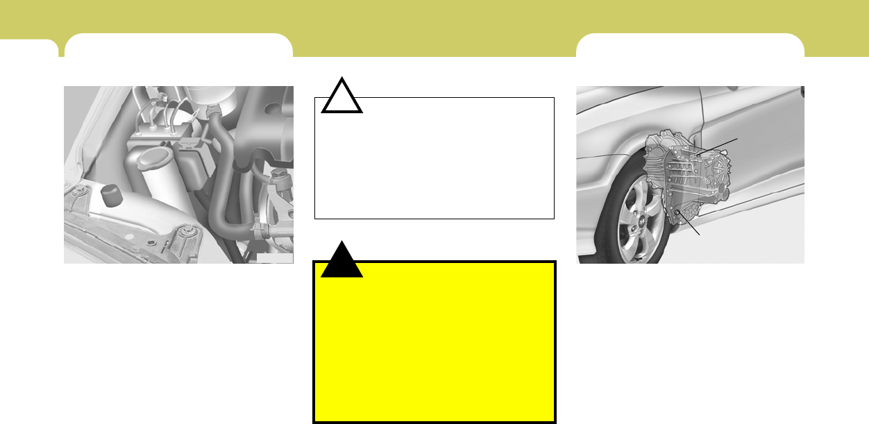
6DO-IT-YOURSELF MAINTENANCE
12
!
G100A04GK-AAT
Transaxle lubricant in the manual transaxle
should be checked at those intervals specified
in the vehicle maintenance schedule in Section
5.
Recommended Oil
Use only HYUNDAI GENUINE PARTS MTF
75W/85 (API GL-4) or equivalents in the manual
transaxle.
Manual Transaxle Oil Capacity
The oil capacity of the manual transaxle:
5 speed: 2.27 U.S. quarts (2.15L)
6 speed: 2.32 U.S. quarts (2.2L)
HGK5009
Filler plug
Drain plug
CHECKING THE TRANSAXLE OIL
(MANUAL)
CAUTION:
o Radiator anti-freeze (engine coolant)
should not be used in the washer system
because it will damage the car’s finish.
o The washer should not be operated if
the washer reservoir is empty. This can
damage the washer fluid pump.
o In areas where water freezes in winter,
use windshield washer antifreeze.
!
FILLING THE WASHER RESERVOIR
G090A03A-AAT
The washer fluid reservoir supplies fluid to the
windshield washer system.
A good quality washer fluid should be used to fill
the washer reservoir. The fluid level should be
checked more frequently during inclement
weather or whenever the washer system is in
more frequent use.
The capacity of the washer reservoir is 3.2 U.S.
quarts (3.0 Liters).
HGK5014
WARNING:
o Windshield washer fluid agents contain
some amounts of alcohol and can be
flammable under certain circumstances.
Do not allow sparks or flame to contact
the washer fluid or the washer fluid
reservoir. Damage to the vehicle or its
occupants could occur.
o Windshield washer fluid is poisonous to
humans and animals. Do not drink wind-
shield washer fluid. Serious injury or
death could occur.
6
DO-IT-YOURSELF MAINTENANCE
13
!WARNING:
It is always better to check the transaxle oil
level when the engine is cool or cold. If the
engine is hot, you should exercise great
caution to avoid burning yourself on hot
engine or exhaust parts.
CHECKING THE TRANSAXLE
FLUID (AUTOMATIC)
G110A01E-AAT
Transaxle fluid in the automatic transaxle should
be checked at those intervals specified in the
vehicle maintenance schedule in Section 5.
NOTE:
Automatic transaxle fluid is basically red
color. As driving distance increases, the
fluid color turns darkish red gradually. It is
a normal condition and you should not
judge the need to replace based upon the
changing color.
You must replace the automatic transaxle
fluid in accordance with intervals specified
in the vehicle maintenance schedule in
section 5.
NOTE:
It is recommended that the manual transaxle
fluid should be checked by an authorized
Hyundai dealer.
G110B05A-AAT
Recommended Fluid
Your Hyundai automatic transaxle is specially
designed to operate with HYUNDAI GENUINE
ATF SP III, DIAMOND ATF SP III, SK ATF SP
III or other brands meeting the SP III specifica-
tion approved by Hyundai Motor Co.. Damage
caused by a nonspecified fluid is not covered by
your new vehicle limited warranty.
CAUTION:
Use of aftermarket ATF additives may cause
damage to the automatic transaxle. Only
use HYUNDAI GENUINE ATF SP III, DIA-
MOND ATF SP III, SK ATF SP III or other
brands meeting the SP III specification ap-
proved by Hyundai Motor Co.. If you are
having your vehicle serviced at a facility
other than a Hyundai dealer, verify ATF is
used for your vehicle.
!
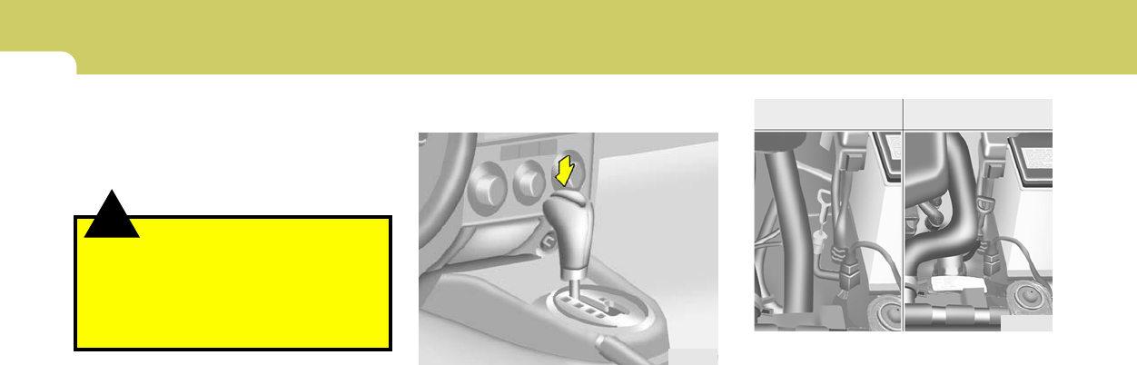
6DO-IT-YOURSELF MAINTENANCE
14
2. Remove the transaxle dipstick, wipe it clean,
reinsert the dipstick as far as it will go, then
remove it again. Now check the fluid level on
the dipstick. It should be in the "HOT" range
on the dipstick.
3. If the transaxle fluid level is low, use a funnel
to add transaxle fluid through the dipstick
tube until the level reaches the "HOT" range.
Do not overfill.
G110D02Y-AAT
To Check the Transaxle Fluid Level
Park the car on level ground with the parking
brake engaged. When the transaxle fluid level
is checked, the transaxle fluid should be at
normal operating temperature and the engine
idling.
While the engine is idling, apply the brakes and
move the gear selector lever from "P" to each
of its other positions — "R", "N", "D" — and then
return to "N" or "P". With the engine still idling:
1. Open the hood, being careful to keep hands,
long hair and clothing clear of any moving
parts.
HGK3025
HGK5007
2.0L 2.7L
!
G110C02Y-AAT
Transaxle Fluid Capacity
The fluid capacity of the automatic transaxle is
8.2 U.S. quarts (7.8 liters).
WARNING:
The transaxle fluid level should be checked
when the engine is at normal operating
temperature. This means that the engine,
radiator, exhaust system etc., are very hot.
Exercise great care not to burn yourself
during this procedure.
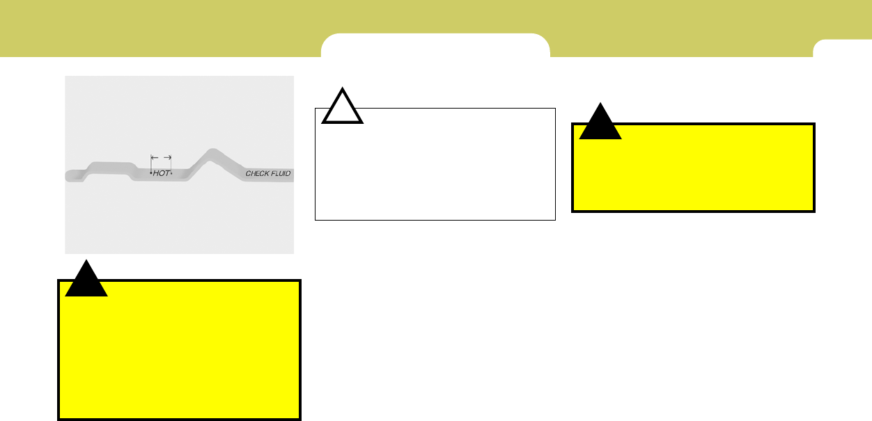
6
DO-IT-YOURSELF MAINTENANCE
15
!
HGK5008
Fluid level should be within this range
WARNING:
The cooling fan is controlled by engine
coolant temperature and may sometimes
operate even when the engine is not run-
ning. Use extreme caution when working
near the blades of the cooling fan, so that
you are not injured by a rotating fan blade.
As the engine coolant temperature de-
creases, the fan will automatically shut off.
This is a normal condition.
CHECKING THE BRAKES
G120A01A-AAT
CAUTION:
Because brakes are essential to the safe
operation of the car, it is suggested that
they be checked and inspected by your
Hyundai dealer. The brakes should be
checked and inspected for wear at those
intervals specified in the vehicle mainte-
nance schedule in Section 5.
!!
G120B01A-AAT
Checking the Brake Fluid Level
WARNING:
Use caution when handling brake fluid. It
can damage your vision if it gets into your
eyes. It will also damage your vehicle’s
paint if spilled on it and not removed imme-
diately.
G120C02A-AAT
Recommended Brake Fluid
Use only hydraulic brake fluid conforming to
DOT 3 or DOT 4 specifications in your braking
system. Follow the instructions printed on the
container.
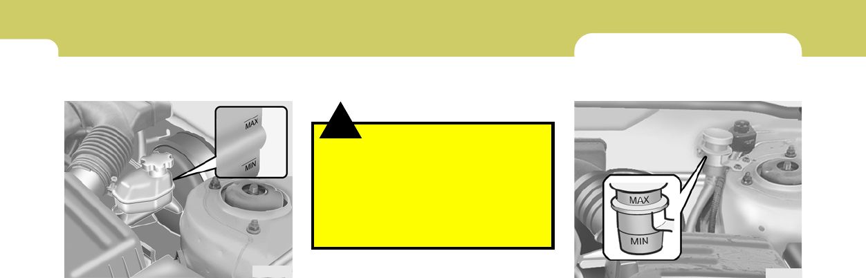
6DO-IT-YOURSELF MAINTENANCE
16 CHECKING THE CLUTCH FLUID
G130A01S-AAT
To Check the Clutch Fluid
The clutch fluid level in the master cylinder
should be checked when performing other un-
der hood services. The system should be
checked for leakage at the same time.
Check to make certain that the clutch fluid level
is always between the "MAX" and "MIN" level
markings on the fluid reservoir. Fill as required.
Fluid loss indicates a leak in the clutch system
which should be inspected and repaired imme-
diately. Consult your Hyundai dealer.
HGK5013
G120D01A-AAT
To Check the Fluid Level
The fluid level in the brake fluid reservoir should
be checked periodically. The level should be
between the "MIN" and "MAX" marks on the side
of the reservoir. If the level is at or below the
"MIN" mark, carefully add fluid to bring it up to
"MAX". Do not overfill.
HGK5012 To add brake fluid, first wipe away any dirt, then
unscrew the fluid reservoir cap. Slowly pour the
recommended fluid into the reservoir. Do not
overfill. Carefully replace the cap on the reser-
voir and tighten.
G120E02A-AAT
Adding Brake Fluid
!WARNING:
Handle brake fluid carefully. It can damage
your vision if it gets into your eyes. Use only
DOT 3 or DOT 4 specification fluid from a
sealed container. Do not allow the fluid can
or reservoir to remain open any longer than
required. This will prevent entry of dirt and
moisture which can damage the brake sys-
tem and cause improper operation.

6
DO-IT-YOURSELF MAINTENANCE
17
!
G130B02A-AAT
To Replace the Fluid
Recommended brake fluid conforming to DOT
3 or DOT 4 specification should be used. The
reservoir cap must be fully tightened to avoid
contamination from foreign matter or moisture.
NOTE:
Do not allow any other liquids to contami-
nate the brake fluid. Seal damage will result.
WARNING:
Use caution when handling brake fluid. It
can damage your vision if you get it in your
eyes. It will also damage your vehicle’s
paint if spilled on it and not removed imme-
diately.
AIR CONDITIONING CARE
G140A01A-AAT
Keeping the Condenser Clean
The air conditioning condenser (and engine
radiator) should be checked periodically for
accumulation of dirt, dead insects, leaves, etc.
These can interfere with maximum cooling ef-
ficiency. When removing such accumulations,
brush or hose them away carefully to avoid
bending the cooling fins.
!
G140C01A-AAT
Lubrication
To lubricate the compressor and the seals in the
system, the air conditioning should be run for at
least 10 minutes each week. This is particularly
important during cool weather when the air
conditioning system is not otherwise in use.
G140B01A-AAT
Checking the Air Conditioning Opera-
tion
1. Start the engine and let it run at a fast idle for
several minutes with the air conditioning set
at the maximum cold setting.
2. If the air coming out of the in-dash vents is
not cold, have the air conditioning system
inspected by your Hyundai dealer.
CAUTION:
Running the air conditioning system for
extended periods of time with a low refrig-
erant level may damage the compressor.
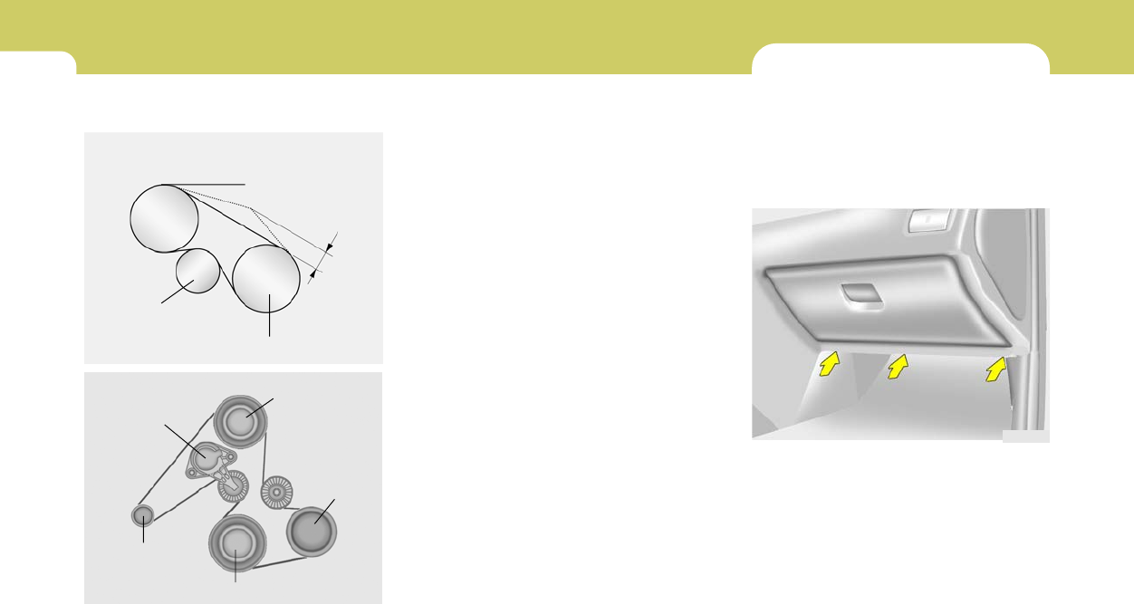
6DO-IT-YOURSELF MAINTENANCE
18 CHANGING THE CLIMATE CON-
TROL AIR FILTER
G145A03GK-GAT
(In front of blower unit) (If installed)
The climate control air filter is located in front of
the evaporator unit behind the glove box.
It helps to decrease the amount of pollutants
entering the car.
1. Remove the mounting screws on the down-
side of the glove box.
HGK2111
G140D01A-AAT
Checking the Compressor Drive Belt When the air conditioning is being used regu-
larly, the compressor drive belt tension should
be checked at least once a month with the
engine turned off.
To check the drive belt tension, press down on
the belt halfway between the engine crankshaft
and compressor pulleys. Pressing with your
finger, you should not be able to deflect this belt
anymore than 1/3 of an inch. If you have the
instruments to check it, with a force of 22
lb.(98N), the deflection should be 0.315 inches
(approx 8.0 mm). If the belt is too loose, have it
adjusted by your Hyundai dealer.
Crankshaft pulley HTB219
A/C
Tension pulley
0.315 in.
(8mm)
2.0L
G190A02B
A/C
comp.
Crankshaft pulley
Power steering
Auto tensioner
Generator
2.7 L
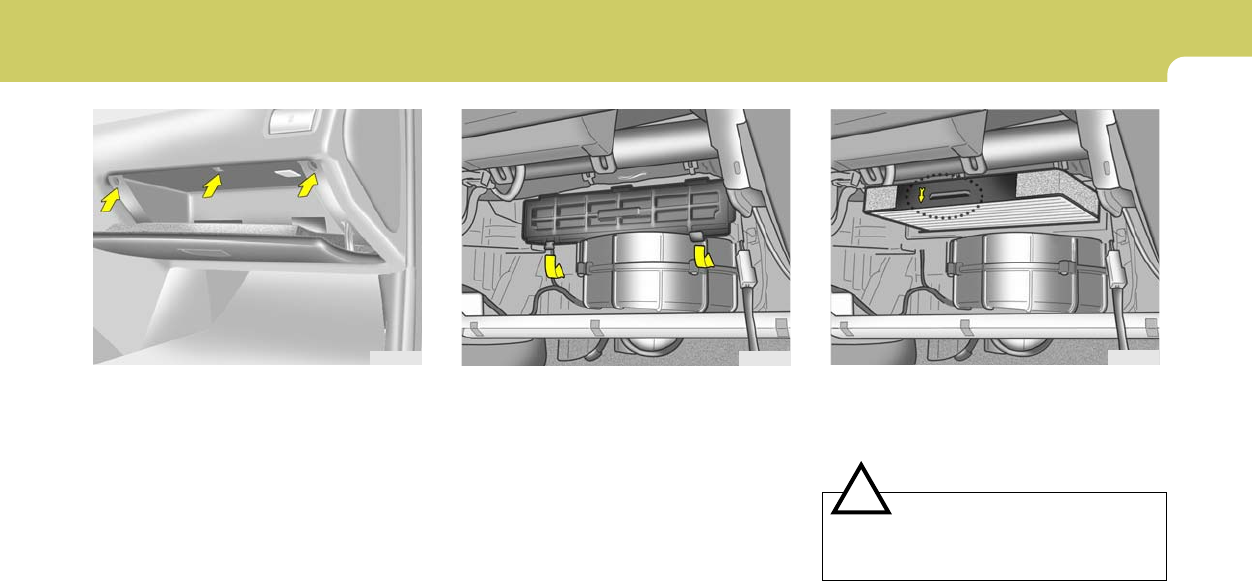
6
DO-IT-YOURSELF MAINTENANCE
19
2. Open the glove box and remove the mount-
ing screws on the upside of the glove box.
3. Remove the filter cover.
HGK2112 HGK2114
4. Replace the climate control air filter with a
new one.
5. Installation is the reverse order of disassem-
bly.
HGK2115
CAUTION:
Be sure to install the climate control air filter
in the direction of the arrow sign. Other-
wise, it may cause noise or deterioration.
!
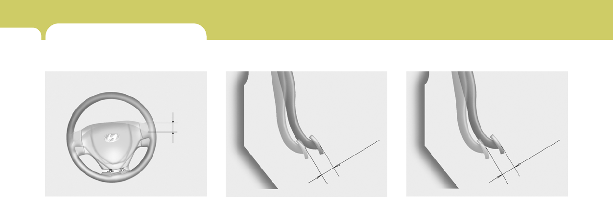
6DO-IT-YOURSELF MAINTENANCE
20
G170A01A-AAT
Brake Pedal
With the engine off, press down on the brake
pedal several times to reduce the vacuum in the
brake booster.
Then, using your hand, press down slowly on
the brake pedal until you feel a change in
resistance. This is the brake pedal free-play.
The free-play should be within the limits speci-
fied in the illustration. If it is not, have it inspected
by your Hyundai dealer and adjusted or re-
paired if necessary.
HXGS508
0.12~0.31 in.
(3~8 mm)
CHECKING THE FREE-PLAY
G150A01A-AAT
Steering Wheel
To check the steering wheel free-play, stop the
car with the wheels pointed straight ahead and
gently move the steering wheel back and forth.
Use very light finger pressure and be sensitive
to changes in resistance that mark the limits of
the free-play. If the free-play is greater than
specified, have it inspected by your Hyundai
dealer and adjusted or repaired if necessary.
HGK5019
1.18 in.
(30 mm)
G160A01A-AAT
Clutch Pedal
With the engine off, press lightly on the clutch
pedal until you feel a change in resistance. This
is the clutch pedal free-play. The free-play
should be within the limits specified in the illus-
tration. If it is not, have it inspected by your
Hyundai dealer and adjusted or repaired if
necessary.
G160A01E
0.24 ~ 0.51 in.
(6~13 mm)
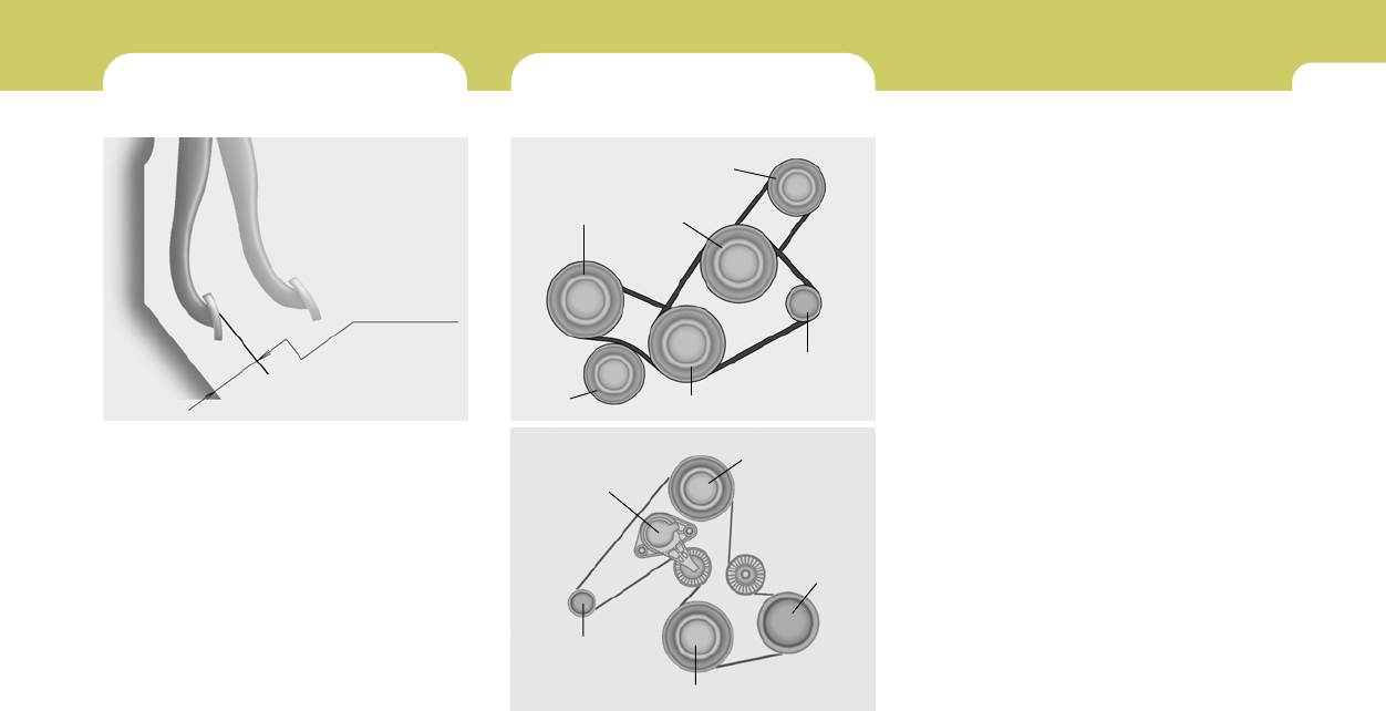
6
DO-IT-YOURSELF MAINTENANCE
21
CHECKING BRAKE PEDAL
CLEARANCE
CHECKING DRIVE BELTS
G190A01A-AATG180A01A-AAT
You need a helper to check the brake pedal
clearance. With the engine running, have your
helper press down on the brake pedal several
times and then hold it down with a force of about
110 lbs (50 kg, 490 N). The brake pedal clear-
ance is the distance from the top surface of the
brake pedal to the asphalt sheeting under the
floor mat.
If the brake pedal clearance is not within the
limits specified in the illustration, have it in-
spected by your Hyundai dealer and adjusted
or repaired if necessary.
G180A01L
1.78 in. (45.1 mm)
Tension
pulley
Generator
G190A01GK
Power
steering
Water pump
pulley
A/C
comp.
2.0L
G190A02B
A/C
comp.
Crankshaft pulley
Power steering
Auto tensioner
Generator
2.7L
Crankshaft pulley
Drive belts should be checked periodically for
proper tension and adjusted if necessary. At the
same time, belts should be examined for cracks,
wear, fraying or other evidence of deterioration
and replaced if necessary.
Belt routing should also be checked to be sure
there is no interference between the belts and
other parts of the engine. After a belt is replaced,
the new belt should be adjusted again after two
or three weeks to eliminate slack resulting from
initial stretching after use.
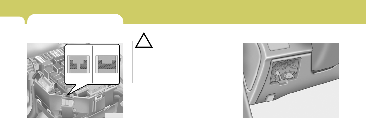
6DO-IT-YOURSELF MAINTENANCE
22
G200B02A-AAT
Replacing Accessory Fuse
The fuse box for the lights and other electrical
accessories will be found low on the dashboard
on the driver’s side. Inside the box you will find
a list showing the circuits protected by each
fuse.
If any of your car’s lights or other electrical
accessories stop working, a blown fuse could
be the reason. If the fuse has burned out, you
will see that the metal strip inside the fuse has
burned through. If you suspect a blown fuse,
follow this procedure:
HGK4003
CHECKING AND REPLACING
FUSES
G200A01GK-AAT
Replacing a Fusible Link
A fusible link will melt if the electrical circuits from
the battery are ever overloaded, thus prevent-
ing damage to the entire wiring harness. (This
could be caused by a short in the system
drawing too much current.) If this ever happens,
have a Hyundai dealer determine the cause,
repair the system and replace the fusible link.
The fusible links are located in a relay box(2.0L
)or below the positive (+) post cover of the
battery (2.7L) for easy inspection.
G200A01E
Good
Bad
!CAUTION:
When replacing a fusible link, never use
anything but a new fusible link with the
same or lower amperage rating. Never use
a piece of wire or a higher-rated fusible link.
This could result in serious damage and
create a fire hazard.
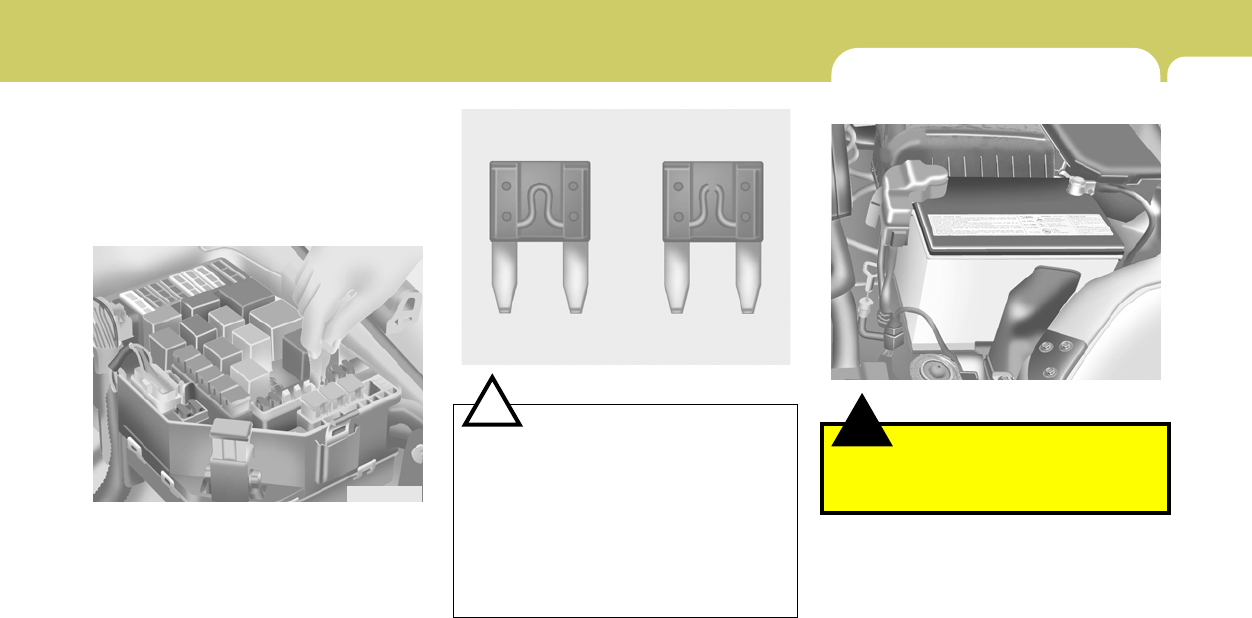
6
DO-IT-YOURSELF MAINTENANCE
23
!CAUTION:
A burned-out fuse indicates that there is a
problem in the electrical circuit. If you re-
place a fuse and it blows as soon as the
accessory is turned on, the problem is
serious and should be referred to a Hyundai
dealer for diagnosis and repair. Never re-
place a fuse with anything except a fuse
with the same or a lower amperage rating.
A higher capacity fuse could cause damage
and create a fire hazard.
G200B02L
Good Burned out
1. Turn off the ignition and all other switches.
2. Open the fuse box and examine each fuse.
Remove each fuse by pulling it toward you
(a small "fuse puller" tool is contained in the
fuse box to simplify this operation).
3. Be sure to check all other fuses, even if you
find one that appears to have burned out.
HXDFL1026-1
4. Replace the blown fuse by pressing a new
fuse of the same rating into place. The fuse
should be a snug fit. If it is not, have the fuse
clip repaired or replaced by a Hyundai dealer.
If you do not have a spare fuse, you may be
able to borrow a fuse of the same or lower
rating from an accessory you can tempo-
rarily get along without (the radio or cigarette
lighter, for example). Always remember to
replace the borrowed fuse.
NOTE:
See page 6-39 for the fuse panel descrip-
tions.
CHECKING THE BATTERY
!
G210A01A-AAT
WARNING:
Batteries can be dangerous! When working
with batteries, carefully observe the follow-
ing precautions to avoid serious injuries.
The fluid in the battery contains a strong solution
of sulfuric acid, which is poisonous and highly
corrosive. Be careful not to spill it on yourself or
the car. If you do spill battery fluid on yourself,
immediately do the following:
D010B01GK
6DO-IT-YOURSELF MAINTENANCE
24
!WARNING:
Always read the following in-
structions carefully when han-
dling a battery.
Keep lighted cigarettes and all
other flames or sparks away from
the battery.
Hydrogen, which is a highly com-
bustible gas, is always present in
battery cells and may explode if
ignited.
Keep batteries out of the reach of
children because batteries con-
tain highly corrosive SULFURIC
ACID. Do not allow battery acid
to contact your skin, eyes, cloth-
ing or paint finish.
If any electrolyte gets into your
eyes, flush your eyes with clean
water for at least 15 minutes and
get immediate medical attention.
If possible, continue to apply
water with a sponge or cloth until
medical attention is received.
o If battery fluid is on your skin, flush the
affected areas with water for at least 15
minutes and then seek medical assistance.
o If battery fluid is in your eyes, rinse out your
eyes with water and get medical assistance
as soon as possible. While you are being
driven to get medical assistance, continue to
rinse your eyes by using a sponge or soft
cloth saturated with water.
o If you swallow battery fluid, drink a large
quantity of water or milk followed by milk of
magnesia, eat a raw egg or drink vegetable
oil. Get medical assistance as soon as
possible.
While batteries are being charged (either by a
battery charger or by the vehicle’s generator),
they produce explosive gases. Always ob-
serve these warnings to prevent injuries from
occurring:
o Charge batteries only in a well ventilated
area.
o Do not permit flames, sparks or smoking in
the area.
o Keep children away from the area.
!
G210B03A-AAT
Checking the Battery
Keep the battery clean. Any evidence of corro-
sion around the battery posts or terminals
should be removed using a solution of house-
hold baking soda and warm water. After the
battery terminals are dry, cover them with a light
coating of grease.
PROPOSITION 65 WARNING:
Battery posts, terminals, and related acces-
sories contain lead and lead compounds,
chemicals known to the state of California
to cause cancer and reproductive harm.
Batteries also contain other chemicals
known to the state of California to cause
cancer. Wash hands after handling.

6
DO-IT-YOURSELF MAINTENANCE
25
!
CHECKING ELECTRIC COOLING
FANS
!
G220A01A-AAT
WARNING:
The cooling fan is controlled by engine
coolant temperature and may sometimes
operate even when the engine is not run-
ning. Use extreme caution when working
near the blades of the coolant fan, so that
you are not injured by a rotating fan blade.
As the engine coolant temperature de-
creases the fan will automatically shut off.
This is a normal condition.
If electrolyte gets on your skin,
thoroughly wash the contacted
area.
If you feel a pain or a burning
sensation, get medical attention
immediately.
Wear eye protection when charg-
ing or working near a battery.
Always provide ventilation when
working in an enclosed space.
o When lifting a plastic-cased battery, ex-
cessive pressure on the case may cause
battery acid to leak, resulting in personal
injury. Lift with a battery carrier or with
your hands on opposite corners.
o Never attempt to charge the battery when
the battery cables are connected.
o The electrical ignition system works with
high voltage.
Never touch these components with the
engine running or the ignition switched
on.
WARNING:
G220C01A-AAT
Checking Condenser Cooling Fan
The condenser coolant fan should come on
automatically whenever the air conditioning is in
operation.
G220B01A-AAT
Checking Engine Cooling Fan
The engine cooling fan should come on auto-
matically if the engine coolant temperature is
high.
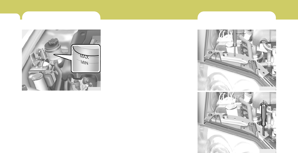
6DO-IT-YOURSELF MAINTENANCE
26 HEADLIGHT AIMING ADJUSTMENT
G290A03GK
G290A03GK-AAT
Low Beam Vertical aiming
Before performing aiming adjustment, make
sure of the following.
G290A04GK
High Beam Vertical aiming
POWER STEERING FLUID LEVEL
G230A03A-AAT
The power steering fluid level should be checked
regularly. To check the power steering fluid
level, be sure the engine is "OFF", then check
to make certain that the power steering fluid
level is between the "MAX" and "MIN" level
markings on the fluid reservoir.
NOTE:
Grinding noise from the power steering
pump may be heard immediately after the
engine is started in extremely cold condi-
tions (below - 4°F). If the noise stops during
warm up, there is no abnormal function in
the system. It is due to a power steering
fluid characteristic in extremely cold condi-
tions.
HGK5011
G240A01A-AAT
POWER STEERING HOSES
It is suggested that you check the power steer-
ing hose connections for fluid leakage at regular
intervals. The power steering hoses should be
replaced if there is severe surface cracking,
scuffing or worn spots. Deterioration of the hose
could cause premature failure.
Recommended Fluid
Use PSF-3 type fluid
NOTE:
Do not start the engine when the power
steering oil reservoir is empty.
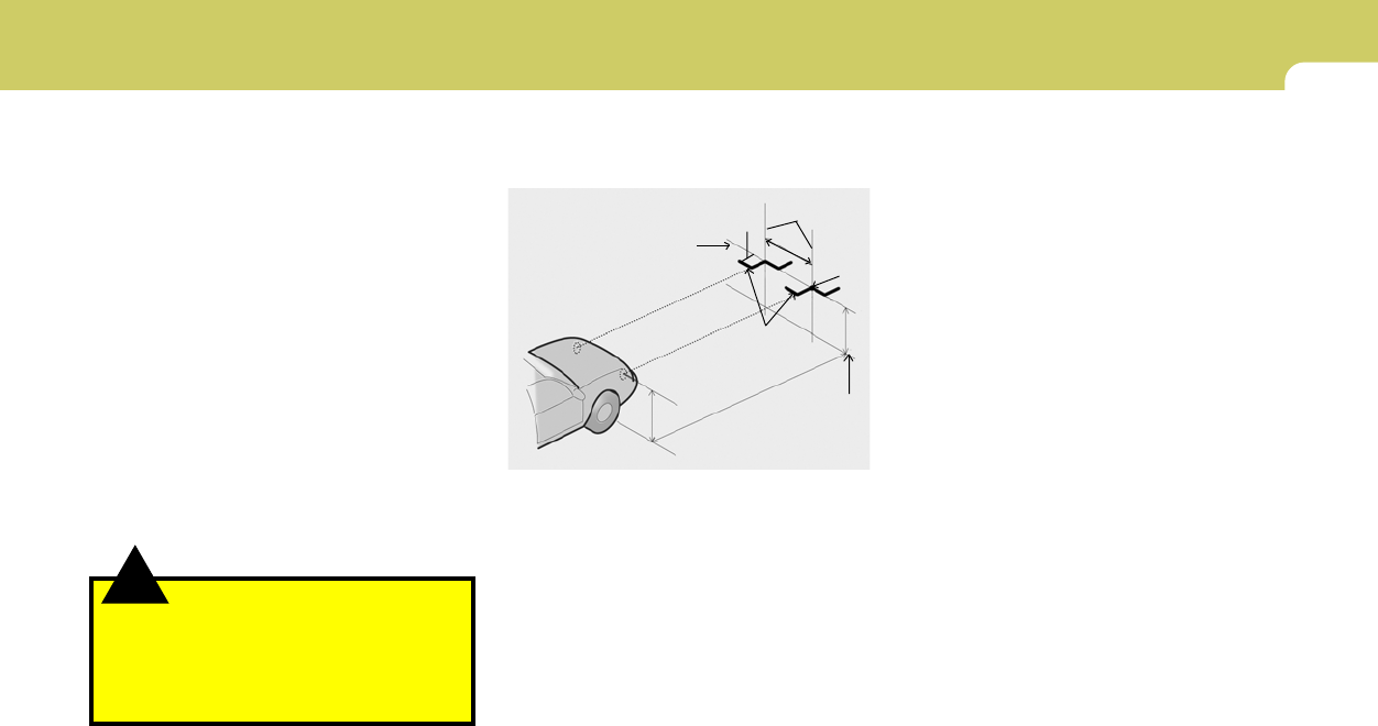
6
DO-IT-YOURSELF MAINTENANCE
27
G290B01GK-AAT
Adjustment After Headlight Assembly
Replacement
If the vehicle has had front body repair and the
headlight assembly has been replaced, the
headlight aiming should be checked using an
aiming screen as shown in the illustration. Turn
on the headlight switch.
1. Adjust headlights so that main axis of light is
parallel to center line of the body and is
aligned with point "P" shown in the illustration.
2. Dotted lines in the illustration show the center
of headlights.
G290B01GK
L
W
H
H
Cut-off line
Ground line
"P"
Horizontal line
Vertical line
0.827 in. (21 mm)
!
1. Keep all tires inflated to the correct pressure.
2. Place the vehicle on level ground and press
the front bumper & rear bumper down sev-
eral times. Place vehicle at a distance of 118
in. (3m) from the test wall.
3. See that the vehicle is unloaded (except for
full levels of coolant, engine oil and fuel, and
spare tire, jack, and tools).
4. Clean the head light lenses and turn on the
headlights.
5. Open the hood.
6. Draw the vertical line (through the center of
each headlight beam pattern) and the hori-
zontal line (through the center of each head-
light beam pattern) on the aiming screen.
And then, draw the parallel line at 0.827 in. (21
mm) under the horizontal line.
7. Adjust each cut-off line of the low beam to the
parallel line with a phillips screwdriver -
VERTICAL AIMING.
WARNING:
Never attempt to adjust the horizontal align-
ment of your headlights. Horizontal aiming
must be adjusted by an authorized Hyundai
dealer to avoid incorrect alignment that will
reduce the effectiveness of your headlights.
SPECIFICATION:
"H"
Horizontal center line of headlights from ground:
Low Beam: 26.7 in. (679mm)
High Beam: 26.5 in. (672mm)
"W"
Distance between each headlight center :
Low Beam: 47.3 in. (1,202mm)
High Beam: 38.0 in. (966mm)
"L"
Distance between the headlights and the wall
that the lights are tested against : 118 in. (3,000
mm)
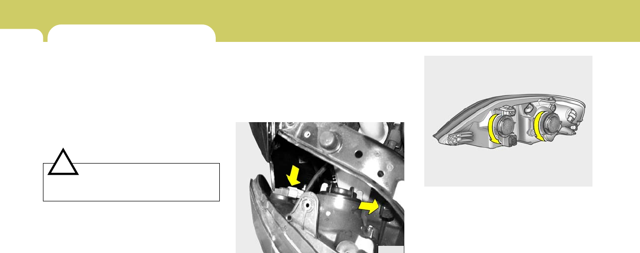
6DO-IT-YOURSELF MAINTENANCE
28
HGK5024
5. Turn the plastic cover counterclockwise
and remove it.
6. Disconnect the connector from the bulb
base in the back of the headlight.
REPLACEMENT OF LIGHT BULBS
!
G260A02A-AAT
Before attempting to replace a light bulb, be sure
the switch is turned to the "OFF" position.
The next paragraph shows how to reach the
light bulbs so they may be changed. Be sure to
replace the burned-out bulb with one of the
same number and wattage rating.
See page 6-38 for the wattage description.
CAUTION:
Keep the lamps out of contact with petro-
leum products, such as oil, gasoline, etc.
G270A01GK-AAT
Headlight and Front Turn Signal Light
1. Allow the bulb to cool. Wear eye protection.
2. Open the engine hood.
3. Always grasp the bulb by its plastic base,
avoid touching the glass.
4. Disconnect the power cord from the bulb
base in the back of the headlight.
HGK5023
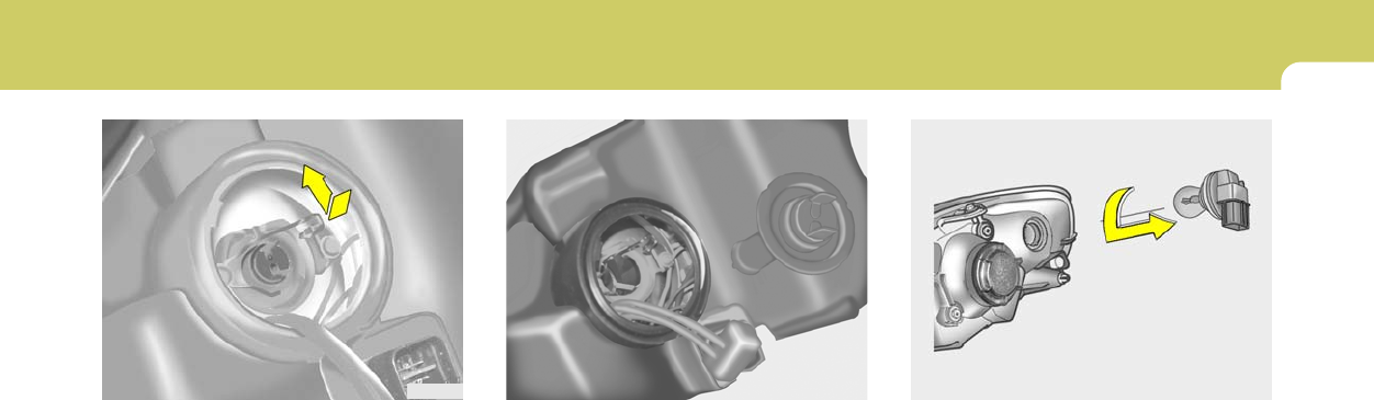
6
DO-IT-YOURSELF MAINTENANCE
29
8. Remove the protective cap from the re-
placement bulb and install the new bulb by
matching the plastic base with the headlight
hole. Reattach the bulb spring and recon-
nect the connector.
9. Use the protective cap and carton to prompt-
ly dispose of the old bulb.
10.Check for proper headlight aim.
HGK5027
HGK5026
7. Push the bulb spring to remove the headlight
bulb.
HGK5036
11.To replace the front turn signal light bulb,
remove from the bulb holder and install the
new bulb.
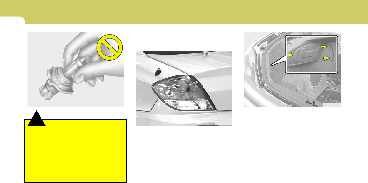
6DO-IT-YOURSELF MAINTENANCE
30
HGK5041
2. To remove the cover of the rear luggage trim,
turn the knob by hand to the counterclock-
wise.
!WARNING:
This halogen bulb contains gas under pres-
sure and if impacted could shatter, result-
ing in flying fragments. Always wear eye
protection when servicing the bulb. Protect
the bulb against abrasions or scratches
and against liquids when lighted. Turn the
bulb on only when installing in a headlight.
Replace the headlight if damaged or cracked.
Keep the bulb out of the reach of children
and dispose of the used bulb with care.
G270A03O
G270B01GK-GAT
Rear Combination Light
(Without woofer speaker)
1. Open the tail gate.
HGK5037
(1)
(2)
(3)
(4)
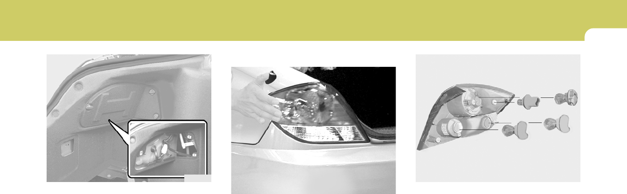
6
DO-IT-YOURSELF MAINTENANCE
31
5. To replace the rear combination light (stop/
tail light, back-up light, turn signal light, side
mark light), take it out from the bulb holder by
turning it counterclockwise.
(1) Stop/Tail light
(2) Back-up light
(3) Turn signal light
(4) Side mark light
6. Install the new bulb.
HGK5044
(1)
(2) (3)
(4)
HGK5042
3. Remove the nut (8mm) with a spanner.
4. To detach the rear combination light hit it
strongly by hand.
HGK5043-1
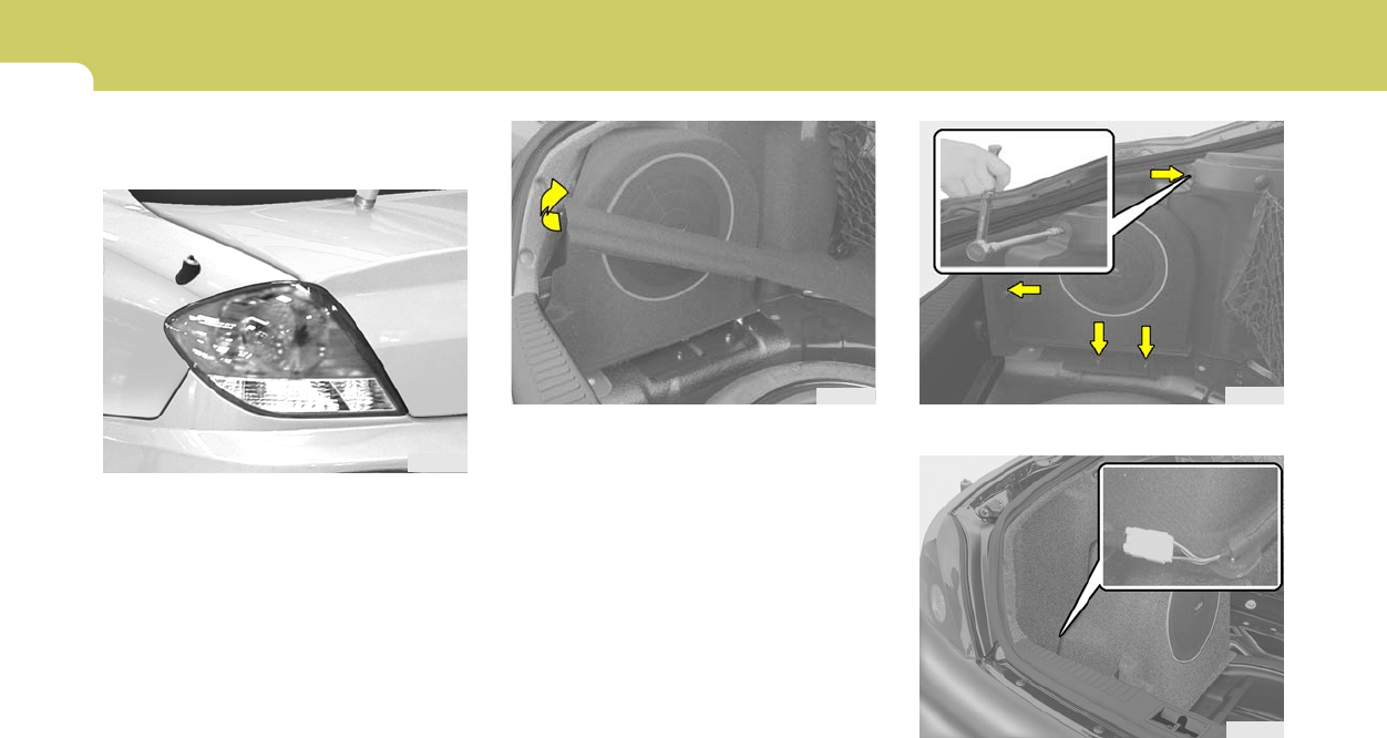
6DO-IT-YOURSELF MAINTENANCE
32
2. Take off the luggage board.
HGK5038
G275B01GK-GAT
Rear Combination Light
(With woofer speaker)
HGK5037
(1)
(2)
(3)
(4)
1. Open the tail gate.
HGK5039
HGK5040
3. Extract the mounting screws (10mm) around
the woofer speaker with a spaner.
4. Disconnect the power cord from the woofer
speaker.
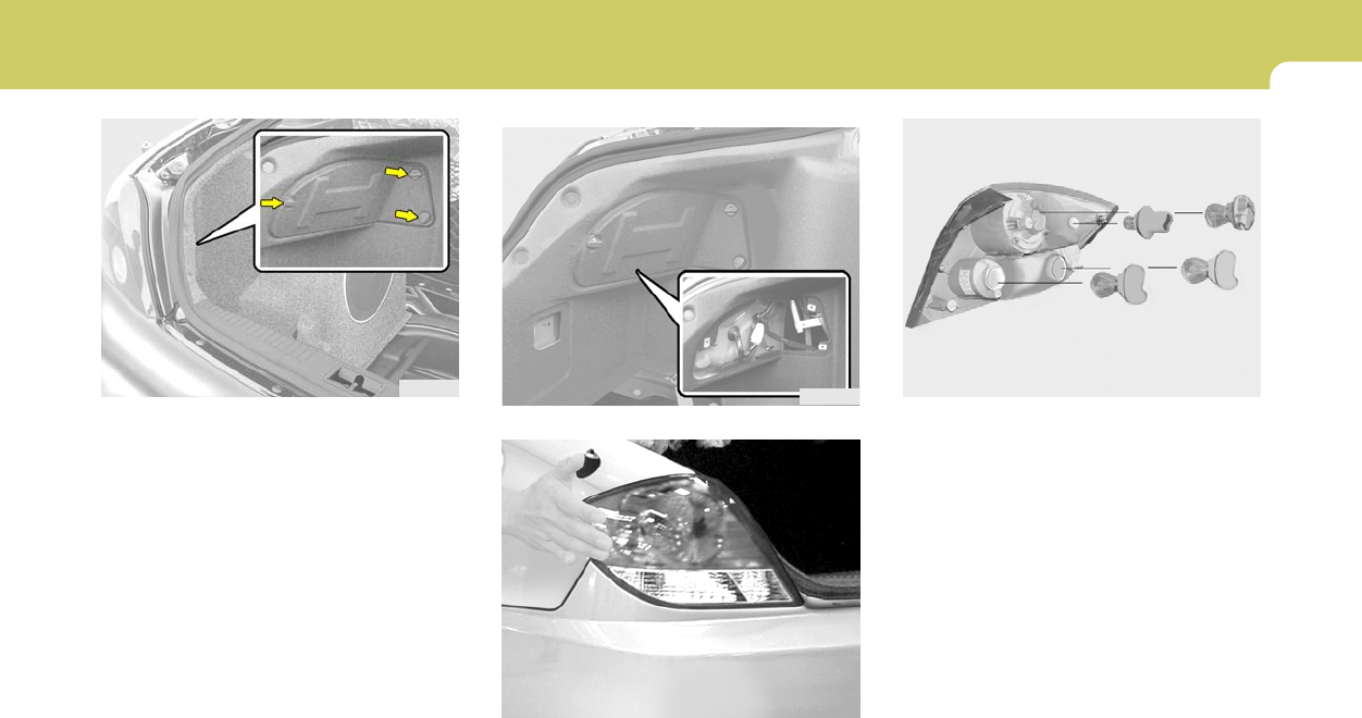
6
DO-IT-YOURSELF MAINTENANCE
33
HGK5044
(1)
(2) (3)
(4)
8. To replace the rear combination light (stop/
tail light, back-up light, turn signal light, side
mark light), take it out from the bulb holder by
turning it counterclockwise.
(1) Stop/Tail light
(2) Back-up light
(3) Turn signal light
(4) Side mark light
9. Install the new bulb.
HGK5041
5. To remove the cover of the rear luggae trim,
turn the knob by hand to the counterclock-
wise.
HGK5042
6. Remove the nut (8mm) with a wrench.
HGK5043-1
7. To detach the rear combination light hit it
strongly by hand.
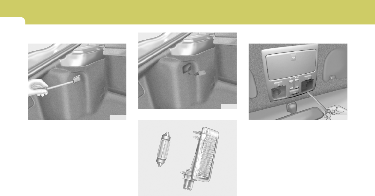
6DO-IT-YOURSELF MAINTENANCE
34
3. Disconnect the power cord.
HGK5046
HTB284
G270C01GK-AAT
Luggage Compartment Light
1. Open the tail gate.
2. Remove the cover with a flat-blade screw-
driver.
HGK5045
4. Replace with a new bulb.
G270G01GK-AAT
Map Light
HGK5047
1. Remove the cover with a flat-blade screw-
driver.
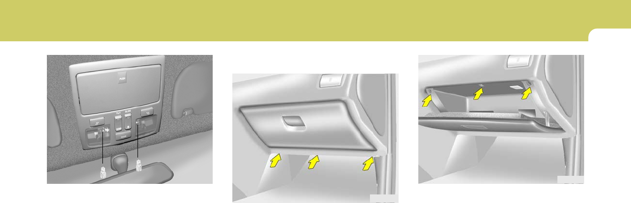
6
DO-IT-YOURSELF MAINTENANCE
35
HGK2112
2. Open the glove box and remove the mount-
ing screws on the upside of the glove box.
HGK5048
G270H01GK-GAT
Glove Box Illuminated Light
1. Remove the mounting screws on the down-
side of the glove box.
HGK2111
2. Replace with a new bulb.
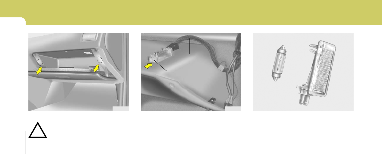
6DO-IT-YOURSELF MAINTENANCE
36
HGK5053
Clip
Power Cord
4. Disconnect the power cord.
5. Remove the glove box illuminated light by
pushing the clip.
3. Remove the glove box by pulling strongly.
CAUTION:
Be careful not to damage the glove box
when pulling the glove box.
!
HGK5052 HTB284
6. Replace with a new bulb.
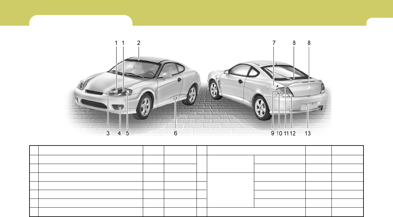
6
DO-IT-YOURSELF MAINTENANCE
37
Part Name
High Mounted Rear
Stop Light
Rear
Combination
Light
License Plate Light
BULB WATTAGE
G280A04GK-AAT
No.
1
2
3
4
5
6
7
Part Name
Head Light (High/Low)
Map Light
Front Position Light
Front Fog Light (If installed)
Front Turn Signal Light/ Front Side Marker Light
Front Door Edge Warning Light
Luggage Compartment Light
Wattage
55/55
10
5
51
28/8
5
5
No.
8
9
10
11
12
13
Wattage
2.4 (LED)
3.5 (LED)
5
27
27/8
27
5
HGK5021A
(High) (Low)
Socket type
Px26d/Px26d
W2.1 X 9.5D
W2.1 X 9.5d
P22d
BA15d
W2.1 X 9.5d
S8.5 / 8.5
With spoiler
Without spoiler
Rear Side Marker Light
Turn Signal Light
Stop/Tail Light
Back-up Light
Socket type
W2.1 X 9.5d
-
BA15s
BA15d
BA15s
W2.1 X 9.5d
S8.5 / 8.5
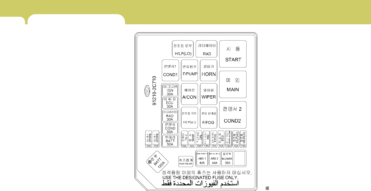
6DO-IT-YOURSELF MAINTENANCE
38 FUSE PANEL DESCRIPTION
G200C01GK-GAT
Engine Compartment
If installed
NOTE:
Not all fuse panel descriptions in this manual may be applicable to your vehicle. It is accurate at the time of printing. When you inspect the
fuse box on your vehicle, refer to the fuse box label.
HGK4005

6
DO-IT-YOURSELF MAINTENANCE
39
PROTECTED COMPONENTS
Generator(2.0L)
BCM BOX(Tail lamp relay,Power connector,Fuse(2,7,12,13,19,20,24)
Condenser fan relay
Radiator fan relay
Engine control relay, Fuel pump relay, A/T control relay,
Generator,ECM(Z2.7L),PCM(2.0L)
Ignition switch,Start relay
ABS/ESP control module,ESP Air bleeding connector
ABS/ESP control module,ESP Air bleeding connector
Blower relay
Injector
Oxygen sensor,Camshaft position sensor, Idle speed control actuator
DRL control module
Front fog lamp relay
TCM(2.7L),ECM(2.7L)
Horn relay,A/C relay
Head lamp relay(High)
Head lamp relay(Low)
FUSERATING
120A
50A
30A
30A
30A
30A
40A
40A
30A
15A
10A
15A
15A
10A
15A
15A
15A
DESCRIPTION
BATT
BATT
COND
RAD
ECU
IGN
ABS 1
ABS 2
BLOWER
INJ
SNSR
DRL
F/FOG
ECU
HORN,A/CON
H/LP (HI)
H/LP (LO)
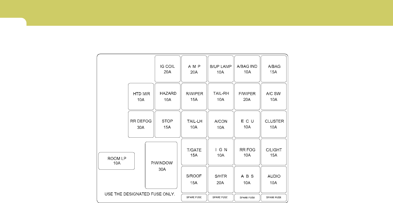
6DO-IT-YOURSELF MAINTENANCE
40
G200D02GK-GAT
Inner Panel
HGK204-E

6
DO-IT-YOURSELF MAINTENANCE
41
DESCRIPTION
IG COIL
AMP
B/UP LAMP
A/BAG IND
A/BAG
HTD MIR
HAZARD
R/WIPER
TAIL-RH
F/WIPER
A/C SW
RR DEFOG
STOP
TAIL-LH
A/CON
ECU
CLUSTER
ROOM LP
P/WINDOW
T/GATE
IGN
RR FOG
C/LIGHT
S/ROOF
S/HTR
ABS
AUDIO
PROTECTED COMPONENTS
Ignition coil(2.7L), Electronic chrome mirror
AMP
Back-up lamp switch,Transaxle range switch,Cruise control module,Stop lamp switch
Instrument cluster (A/BAG IND.)
SRS control module
Mirror defogger
Hazard relay
Rear wiper motor,Rear intermittent wiper relay
Right tail lamps,Glove box lamp
Front wiper motor,Front wiper relay
Blower relay,Blower motor
Defogger relay
Stop lamp switch,Burglar alarm horn relay,Folding/Unfolding rely
Left tail lamps
A/C control module, Blower relay
ECM, Multi gauge unit, TCM, Vehicle speed sensor
Instrument cluster (Power), Per-excitation resister, DRL Control module,Generator
Room lamp,Clock,Audio,Data link connector,Multi gauge unit
Power window relay
Trunk lid switch
AQS sensor,Head lamp relay,DRL Control module
Rear fog lamp
Cigarette lighter,Outside mirror switch
Sunroof,Power door lock/Unlock relay
Seat warmer
ESP/ABS control module
Audio,Digital clock
FUSERATING
20A
20A
10A
10A
15A
10A
10A
15A
10A
20A
10A
30A
15A
10A
10A
10A
10A
10A
30A
15A
10A
10A
15A
15A
20A
10A
10A

EMISSION CONTROL SYSTEMS
7
Emission Control System ............................................. 7-2
Catalytic Converter ....................................................... 7-3
7

7EMISSION CONTROL SYSTEMS
2EMISSION CONTROL SYSTEM
H010D01A-AAT
3. Exhaust Emission Control System
The Exhaust Emission Control System is a
highly effective system which controls exhaust
emissions while maintaining good vehicle per-
formance.
H010B01A-AAT
1. Crankcase Emission Control
System
The Positive Crankcase Ventilation System is
employed to prevent air pollution caused by
blow-by gases being emitted from the crank-
case. This system supplies fresh filtered air to
the crankcase through the air intake hose.
Inside the crankcase, the fresh air mixes with
blow-by gases, which then pass through the
PCV valve and into the induction system.
H010A02GK-AAT
Your Hyundai is equipped with an emission
control system to meet all requirements of the
U.S. Environmental Protection Agency or Cali-
fornia Air Resources Board.
There are three emission control systems which
are as follows.
1) Crankcase Emission Control System
2) Evaporative Emission Control System
3) Exhaust Emission Control System
In order to ensure the proper function of the
emission control systems, it is recommended
that you have your car inspected and main-
tained by an authorized Hyundai dealer in ac-
cordance with the maintenance schedule in this
manual.
Caution for the Inspection and Maintenance
Test (Vehicle with Electronic Stability Pro-
gram)
o To prevent the vehicle from misfiring
during dynamometer testing, discon-
nect the ABS connector located inside
of the wheel guard (driver side).
o For more information, see shop manual
(BR Group, Wheel Speed Sensor).
Canister
Fuel vapors generated inside the fuel tank are
absorbed and stored in the onboard canister.
When the engine is running, the fuel vapors
absorbed in the canister are drawn into the
induction system through the purge control
solenoid valve.
Purge Control Solenoid Valve (PCSV)
The purge control solenoid valve is controlled
by the Engine Control Module (ECM); when the
engine coolant temperature is low during idling,
the PCSV closes so that evaporated fuel is not
taken into the engine. After the engine warms-
up during ordinary driving, the PCSV opens to
introduce evaporated fuel to the engine.
H010C01S-AAT
2. Evaporative Emission Control (Includ-
ing ORVR: Onboard Refueling Vapor
Recovery) System
The Evaporative Emission Control System is
designed to prevent fuel vapors from escaping
into the atmosphere.
(The ORVR system is designed to allow the
vapors from the fuel tank to be loaded into a
canister while refueling at the gas station, pre-
venting the escape of fuel vapors into the
atmosphere.)
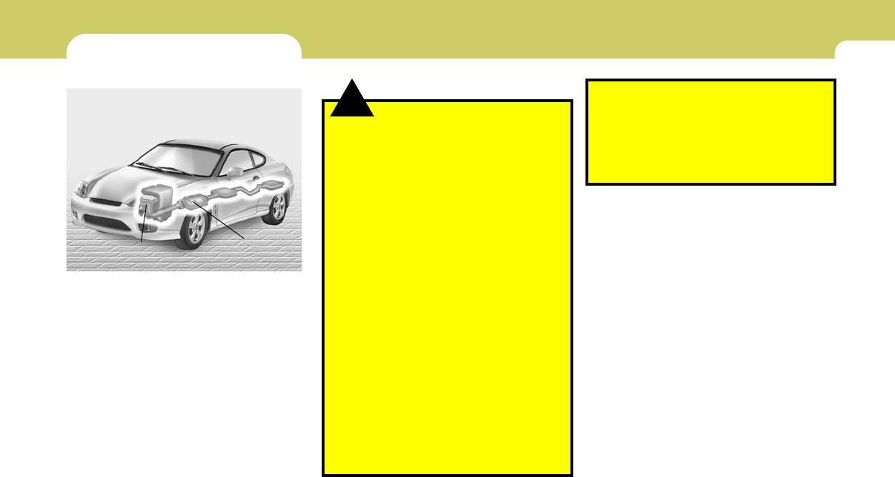
7
EMISSION CONTROL SYSTEMS
3
CATALYTIC CONVERTER
H020A01A-AAT
All Hyundai vehicles are equipped with a mono-
lith type three-way catalytic converter to re-
duce the carbon monoxide, hydrocarbons and
nitrogen oxides contained in the exhaust gas.
Exhaust gases passing through the catalytic
converter may cause it to operate at a very high
temperature. The introduction of large amounts
of unburned gasoline into the exhaust may
cause the catalytic converter to overheat and
create a fire hazard. This risk may be reduced
by observing the following:
HGK5061
Catalytic Converter
(California)
Catalytic Converter
(Federal, California)
!WARNING:
o Use unleaded fuel only.
o Maintain the engine in good operating
condition. Extremely high catalytic con-
verter temperatures can result from im-
proper operation of the electrical, igni-
tion or multiport electronic fuel injec-
tion.
o If your engine stalls, pings, knocks, or is
hard to start, have your Hyundai dealer
inspect and repair the problem as soon
as possible.
o Avoid driving with a very low fuel level.
Running out of gasoline may cause the
engine to misfire and result in damage to
the catalytic converter.
o Avoid idling the engine for periods
longer than 10 minutes.
o The vehicle should not be pushed or
pulled to get started. This may cause the
catalytic converter to overheat and cre-
ate a fire hazard.
o Do not touch the catalytic converter or
any other part of the exhaust system
while the catalytic converter is hot. Shut
off the engine, wait for at least one hour
before touching the catalytic converter
or any other part of the exhaust system.
o Remember that your Hyundai dealer is
your best source of assistance.
o Do not stop your Hyundai over any com-
bustible material such as grass, paper,
leaves or rags. These materials might
contact the hot catalytic converter and a
fire might result.

Vehicle Identification Number (VIN) .............................. 8-2
Engine Number ............................................................. 8-2
Recommended Inflation Pressures ............................... 8-3
Tire Sidewall Labeling ................................................... 8-5
Tire Terminology and Definitions................................... 8-7
Snow Tires .................................................................... 8-9
Tire Chains.................................................................. 8-10
Tire Rotation................................................................ 8-10
Tire Balancing ............................................................. 8-11
Tire Traction ................................................................ 8-11
When to Replace Tires ............................................... 8-12
Spare Tire and Tools................................................... 8-13
Warranties for Your Hyundai Vehicle .......................... 8-13
Consumer Information................................................. 8-13
Reporting Safety Defects ............................................ 8-16
Binding Arbitration of Warranty Claims ....................... 8-16
CONSUMER INFORMATION, REPORTING
SAFETY DEFECTS & BINDING
ARBITRATION OF WARRANTY CLAIMS
8
8
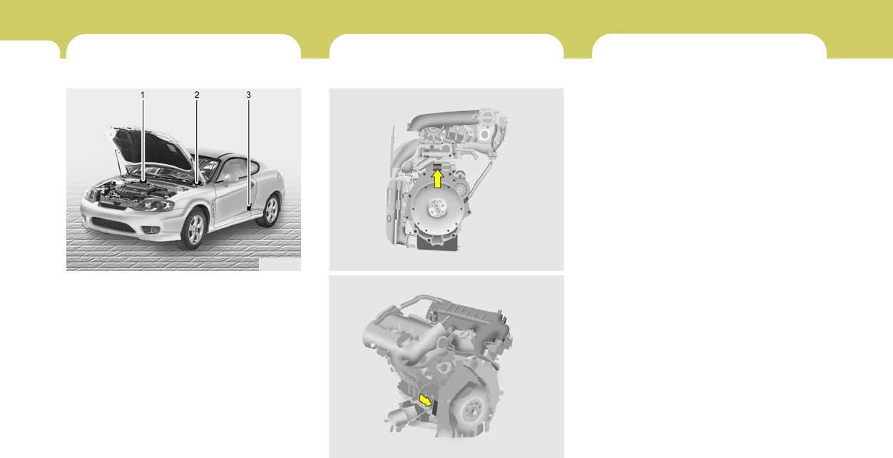
8CONSUMER INFORMATION, REPORTING SAFETY DEFECTS & BINDING ARBITRATION OF WARRANTY CLAIMS
2ENGINE NUMBER
VEHICLE IDENTIFICATION
NUMBER (VIN)
I010B01A-AATI010A01A-AAT
The vehicle identification number (VIN) is the
number used in registering your car and in all
legal matters pertaining to its ownership, etc. It
can be found in three different places on your
car:
1. On the bulkhead between the engine and
passenger compartments.
2. On the left top side of the instrument panel
where it can be seen by looking down through
the windshield.
3. On the lower side of the center pillar outer
panel.
The engine number is stamped on the engine
block as shown in the drawing.
HGK220A
TIRES
I020A02A-AAT
TIRE INFORMATION
The tires supplied on your new Hyundai
are chosen to provide the best perfor-
mance for normal driving.
If you ever have questions about your
tire warranty and where to obtain ser-
vice, see the tire manufacture's booklet
included with your vehicle's Owner's
Manual Literature Kit.
I010B01B
2.7L
HFO6003
2.0L
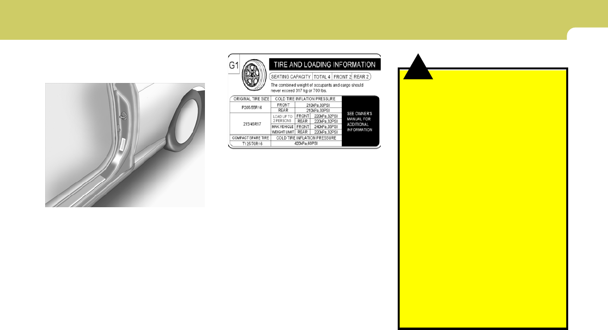
8
CONSUMER INFORMATION, REPORTING SAFETY DEFECTS & BINDING ARBITRATION OF WARRANTY CLAIMS
3
I030A03JM-AAT
RECOMMENDED COLD TIRE INFLA-
TION PRESSURES
Tire label located on the driver's side of
the center pillar outer panel gives the
cold tire pressures recommended for
your vehicle with the original tire size,
the number of people that can be in your
vehicle and vehicle capacity weight.
These pressures were chosen to pro-
vide the most satisfactory combination
of ride comfort, tire wear and stability
under normal conditions. Tire pressures
should be checked at least monthly.
Proper tire inflation pressures should
be maintained for these reasons:
I030B01GK
HGK6003
!WARNING:
o Inspect your tires frequently for
proper inflation as well as wear
and damage. Always use a tire
pressure gauge.
o Tires with too much or too little
pressure wear unevenly causing
poor handling, loss of vehicle
control, and sudden tire failure
leading to accidents, injuries, and
even death. The recommended
cold tire pressure for your vehicle
can be found in this manual and
on the tire label located on the
driver's side of the center pillar.
o Worn tires can cause accidents.
Replace tires that are worn, show
uneven wear, or are damaged.
o Remember to check the pressure
of your spare tire. Hyundai recom-
mends that you check the spare
every time you check the pressure
of the other tires on your vehicle.

8CONSUMER INFORMATION, REPORTING SAFETY DEFECTS & BINDING ARBITRATION OF WARRANTY CLAIMS
4
!
NOTE:
o Underinflation also results in ex-
cessive wear, poor handling and
reduced fuel economy. Wheel de-
formation also is possible. Keep
your tire pressures at the proper
levels. If a tire frequently needs
refilling, have it checked by your
Hyundai Dealer.
o Overinflation produces a harsh
ride, excessive wear at the center
of the tire tread, and a greater
possibility of damage from road
hazards.
WARNING:
Overinflation or underinflation can
reduce the tire life, adversely affect
vehicle handling, and lead to sud-
den tire failure. This could rusult in
loss of vehicle control and potential
injury.
CAUTION:
Always observe the following:
o Check pressures when the tires
are cold. (After the vehicle has
been parked for at least three hours
or hasn't been driven more than 1
mile (1.6 km) since starting up.)
o Check the pressure of your spare
tire each time you check the pres-
sure of other tires.
o Worn, old tires can cause acci-
dents. If your tread is badly worn,
or if your tires have been dam-
aged, replace them.
!

8
CONSUMER INFORMATION, REPORTING SAFETY DEFECTS & BINDING ARBITRATION OF WARRANTY CLAIMS
5
label, no further adjustment is neces-
sary. If the pressure is low, add air until
you reach the recommended amount.
If you overfill the tire, release air by
pushing on the metal stem in the center
of the tire valve. Recheck the tire pres-
sure with the tire gage. Be sure to put
the valve caps back on the valve stems.
They help prevent leaks by keeping out
dirt and moisture.
I035A01JM-AAT
CHECKING TIRE INFLATION PRES-
SURE
Check your tires once a month or more.
Also, check the tire pressure of the
spare tire.
How to Check
Use a good quality gage to check tire
pressure. You can not tell if your tires
are properly inflated simply by looking
at them. Radial tires may look properly
inflated even when they're underinflated.
Check the tire's inflation pressure when
the tires are cold. - "Cold" means your
vehicle has been sitting for at least
three hours or driven no more than 1
mile (1.6 km).
Remove the valve cap from the tire
valve stem. Press the tire gage firmly
onto the valve to get a pressure mea-
surement. If the cold tire inflation pres-
sure matches the recommended pres-
sure on the tire and loading information
Federal law requires tire manufacturers
to place standardized information on
the sidewall of all tires. This information
identifies and describes the fundamen-
tal characteristics of the tire and also
provides the tire identification number
(TIN) for safety standard certification.
The TIN can be used to identify the tire
in case of a recall.
I030B01GK-GAT
TIRE SIDEWALL LABELING
I030B04JM
1
23
4
5, 6
7
1

8CONSUMER INFORMATION, REPORTING SAFETY DEFECTS & BINDING ARBITRATION OF WARRANTY CLAIMS
6
1. Manufacturer or Brand name
o Manufacturer or Brand name is
shown.
2. Tire size
(example: P215/45R17 87V)
o The "P" indicates the tire is de-
signed for passenger vehicles.
A "T" is the designation for a tem-
porary spare tire.
o Three-digit number (215): This num-
ber gives the width in millimeters
of the tire from sidewall edge to
sidewall edge.
o Two-digit number (45): This num-
ber, known as the aspect ratio,
gives the tire's ratio of height to
width.
o R: The "R" stands for radial.
o Two-digit number (17): This num-
ber is the wheel or rim diameter in
inches.
o Two digit number (87): This num-
ber is the tire's load index. It is a
measurement of how much weight
each tire can support.
o V: Speed Rating. The speed rating
denotes the speed at which a tire is
designed to be driven for extended
periods of time. The ratings range
from "A" to "Z" (98 to 186 MPH).
3. TIN (Tire Identification Number) for
new tire (example: DOT XX XX XXX
XXXX)
o DOT: Abbreviation for the "Depart-
ment of Transportation". The sym-
bol can be placed above, below or
to the left or right of the Tire Iden
tification Number. Indicates tire is
in compliance with the U.S. De-
partment of Transportation Motor
Vehicle Safety Standards.
o 1st two-digit code: Manufacturer's
identification mark
o 2nd two-digit code: Tire size
o 3rd three-digit code: Tire type code
(Optional)
o 4th four-digit code: Date of Manu-
facture
o Four numbers represent the week
and year the tire was built. For
example, the numbers 3105 means
the 31st week of 2005.
4. Tire ply composition and material
The number of layers or plies of
rubbercoated fabric in the tire. Tire
manufacturers also must indicate
the materials in the tire, which in-
clude steel, nylon, polyester, and
others. The letter "R" means radial
ply construction; the letter "D" means
diagonal or bias ply construction;
and the letter "B" means belted-bias
ply construction.
5. Maximum permissible inflation
pressure
This number is the greatest amount
of air pressure that should be put in
the tire. Do not exceed the maximum
permissible inflation pressure. Refer
to the Tire and Loading Information
label for recommended inflation pres-
sure.

8
CONSUMER INFORMATION, REPORTING SAFETY DEFECTS & BINDING ARBITRATION OF WARRANTY CLAIMS
7
6. Maximum load rating
This number indicates the maximum
load in kilograms and pounds that
can be carried by the tire. When
replacing the tires on the vehicle,
always use a tire that has the same
load rating as the factory installed
tire.
7. Uniform Tire Quality Grading
(UTQG):
Tire manufacturers are required to
grade tires based on three perfor-
mance factors: treadwear, traction
and temperature resistance. For more
information, see Uniform Tire Qual-
ity Grading on page 8-14.
I030D01JM-AAT
TIRE TERMINOLOGY AND DEFINI-
TIONS
Air Pressure: The amount of air inside
the tire pressing outward on the tire. Air
pressure is expressed in pounds per
square inch (psi) or kilopascal (kPa).
Accessory Weight: This means the
combined weight of optional accesso-
ries. Some examples of optional ac-
cessories are, automatic transmission,
power seats, and air conditioning.
Aspect Ratio: The relationship of a
tire's height to its width.
Belt: A rubber coated layer of cords that
is located between the plies and the
tread. Cords may be made from steel or
other reinforcing materials.
Bead: The tire bead contains steel
wires wrapped by steel cords that hold
the tire onto the rim.
Bias Ply Tire: A pneumatic tire in which
the plies are laid at alternate angles
less than 90 degrees to the centerline of
the tread.
Cold Tire Pressure: The amount of air
pressure in a tire, measured in pounds
per square inch (psi) or kilopascals
(kPa) before a tire has built up heat from
driving.
Curb Weight: This means the weight of
a motor vehicle with standard and op-
tional equipment including the maxi-
mum capacity of fuel, oil and coolant,
but without passengers and cargo.
DOT Markings: A code molded into the
sidewall of a tire signifying that the tire
is in compliance with the U.S. Depart-
ment of Transportation motor vehicle
safety standards. The DOT code in-
cludes the Tire Identification Number
(TIN), an alphanumeric designator which
can also identify the tire manufacturer,
production plant, brand and date of
production.
GVWR: Gross Vehicle Weight Rating
GAWR FRT: Gross Axle Weight Rating
for the front Axle.
GAWR RR: Gross Axle Weight Rating
for the rear axle.

8CONSUMER INFORMATION, REPORTING SAFETY DEFECTS & BINDING ARBITRATION OF WARRANTY CLAIMS
8
Intended Outboard Sidewall: The side
of an asymmetrical tire, that must al-
ways face outward when mounted on a
vehicle.
Kilopascal (kPa): The metric unit for
air pressure.
Load Index: An assigned number rang-
ing from 1 to 279 that corresponds to
the load carrying capacity of a tire.
Maximum Inflation Pressure: The
maximum air pressure to which a cold
tire may be inflated. The maximum air
pressure is molded onto the sidewall.
Maximum Load Rating: The load rat-
ing for a tire at the maximum permis-
sible inflation pressure for that tire.
Maximum Loaded Vehicle Weight:
The sum of curb weight; accessory
weight; vehicle capacity weight; and
production options weight.
Normal Occupant Weight: The num-
ber of occupants a vehicle is designed
to seat multiplied by 150 pounds (68
kg).
Occupant Distribution: Designated
seating positions.
Outward Facing Sidewall: The side of
a asymmetrical tire that has a particular
side that faces outward when mounted
on a vehicle. The side of the tire that
contains a whitewall, bears white letter-
ing or bears manufacturer, brand and or
model name molding that is higher or
deeper than the same moldings on the
other sidewall of the tire.
Passenger (P-Metric) Tire: A tire used
on passenger cars and some light duty
trucks and multipurpose vehicles.
Recommended Inflation Pressure:
Vehicle manufacturer's recommended
tire inflation pressure and shown on the
tire placard.
Radial Ply tire: A pneumatic tire in
which the ply cords that extend to the
beads are laid at 90 degrees to the
centerline of the tread.
Rim: A metal support for a tire and upon
which the tire beads are seated.
Sidewall: The portion of a tire between
the tread and the bead.
Speed Rating: An alphanumeric code
assigned to a tire indicating the maxi-
mum speed at which a tire can operate.
Traction: The friction between the tire
and the road surface. The amount of
grip provided.
Tread: The portion of a tire that comes
into contact with the road.
Treadwear Indicators: Narrow bands,
sometimes called "wear bars," that show
across the tread of a tire when only 2/32
inch of tread remains.
UTQGS: Uniform Tire Quality Grading
Standards, a tire information system
that provides consumers with ratings
for a tire's traction, temperature and
treadwear. Ratings are determined by
tire manufacturers using government
testing procedures. The ratings are
molded into the sidewall of the tire.

8
CONSUMER INFORMATION, REPORTING SAFETY DEFECTS & BINDING ARBITRATION OF WARRANTY CLAIMS
9
I040A01S-AAT
SNOW TIRES
If you equip your car with snow tires,
they should be the same size and have
the same load capacity as the original
tires. Snow tires should be installed on
all four wheels; otherwise, poor han-
dling may result.
Snow tires should carry 4 psi (28 kPa)
more air pressure than the pressure
recommended for the standard tires on
the tire label on the driver side center
pillar outer panel or up to the maximum
pressure shown on the tire sidewall
whichever is less.
Do not drive faster than 75 mph (120
km/h) when your car is equipped with
snow tires.
Vehicle Capacity Weight: The number
of designated seating positions multi-
plied by 150 lbs. (68 kg) plus the rated
cargo and luggage load
Vehicle Maximum Load on the Tire:
Load on an individual tire due to curb
and accessory weight plus maximum
occupant and cargo weight.
Vehicle Normal Load on the Tire:
That load on an individual tire that is
determined by distributing to each axle
its share of the curb weight, accessory
weight, and normal occupant weight
and driving by 2.
Vehicle Placard: A label permanently
attached to a vehicle showing the origi-
nal equipment tire size and recom-
mended inflation pressure
I040B01JM-AAT
ALL SEASON TIRES
Hyundai specifies all season tires on
some models to provide good perfor-
mance for use all year round, including
snowy and icy road conditions. All sea-
son tires are identified by ALL SEASON
and/or M+S (Mud and Snow) on the tire
sidewall. Snow tires have better snow
traction than all season tires an may be
more appropriate in some areas.
I040C01JM-AAT
SUMMER TIRES
Hyundai specifies summer tires on some
models to provide superior performance
on dry roads. Summer tire performance
is substantrally reduced in snow and ice.
Summer tires do not have the tire trac-
tion rating M+S (Mud and Snow) on the
tire side wall. if you plan to operate your
vehicle in snowy or icy conditions.
Hyundai recommends the use of snow
tires or all season tires on all four wheels.
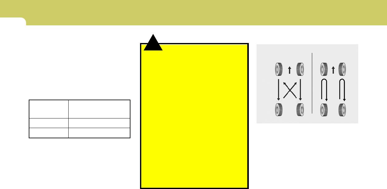
8CONSUMER INFORMATION, REPORTING SAFETY DEFECTS & BINDING ARBITRATION OF WARRANTY CLAIMS
10
I060A02GK-AAT
TIRE ROTATION
Tires should be rotated every 6,000
miles (10,000 km). If you notice that
tires are wearing unevenly between ro-
tations, have the car checked by a
Hyundai dealer so the cause may be
corrected.
After rotating, adjust the tire pressures
and be sure to check wheel nut torque.
HGK5016
!
I050A04GK-AAT
TIRE CHAINS
Tire chains, if necessary, should be
installed on the front wheels. Be sure
that the chains are installed in accor-
dance with the manufacturer's instruc-
tions. Refer to the following informa-
tion.
WARNING:
o When driving on roads covered
with snow or ice, drive at less than
20 mph.
o Use the SAE "S" class or wire &
plastic chains.
o Don't use a tire chains on a vehicle
equipped with aluminium wheels.
If it is unavoidable use wire-type
chains.
o Use tire chains less than 0.39 in.
(10 mm) for "16, and "17 tires.
o If you have noise caused by chains
contacting the body, retighten the
chain to avoid contact with the
vehicle body.
o To prevent body damage, retighten
the chains after driving 0.3~0.6
miles.
Tire size
205/55 R 16
215/45 R 17
Snow Chain
Thickness
Max. 0.39 in. (10 mm)
Max. 0.39 in. (10 mm)
16" Tire 17" Tire
To minimize tire and chain wear, do not
continue to use tire chains when they
are no longer needed.
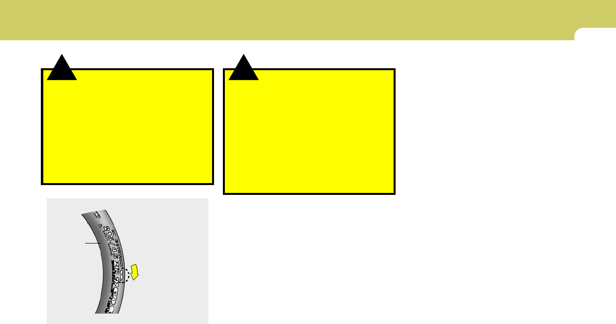
8
CONSUMER INFORMATION, REPORTING SAFETY DEFECTS & BINDING ARBITRATION OF WARRANTY CLAIMS
11
I070A01A-AAT
TIRE BALANCING
A tire that is out of balance may affect
handling and tire wear. The tires on your
Hyundai were balanced before the car
was delivered but may need balancing
again during the years you own the car.
Whenever a tire is dismounted for re-
pair, it should be rebalanced before
being reinstalled on the car.
!WARNING:
o Do not use the temporary spare
tire for tire rotation.
o Do not mix bias ply and radial ply
tires under any circumstances.
This may cause unusual handling
characteristics that could result in
death, serious injury, or property
damage.
!WARNING:
When rotating the 215/45 R17 tires,
the tires must be mount following
the "ROTATION" direction marked
on the sidewall of the tires.
If rotating the tires from the left side
to the right side and from the right
side to the left side, separate the
wheel from the tire and then remount
them.
Sidewall
HGK5018
Tire rotation
direction
I080A01A-AAT
TIRE TRACTION
Tire traction can be reduced if you drive
on worn tires, tires that are improperly
inflated or on slippery road surfaces.
Tires should be replaced when tread
wear indicators appear. To reduce the
possibility of losing control, slow down
whenever there is rain, snow or ice on
the road.
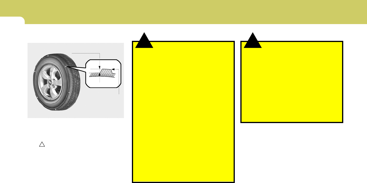
8CONSUMER INFORMATION, REPORTING SAFETY DEFECTS & BINDING ARBITRATION OF WARRANTY CLAIMS
12
!!
I090A04A-AAT
WHEN TO REPLACE TIRES
HGK5015
TWI indicator
0.06 in. (1.6 mm) WARNING:
To reduce the chance or serious or
fatal injuries from an accident caused
by tire failure or loss of vehicle con-
trol:
o Replace tires that are worn, show
uneven wear, or are damaged.
Worn tires can cause loss of brak-
ing effectiveness, steering con-
trol, and traction.
o Do not drive your vehicle with too
little or too much pressure in your
tires. This can lead to uneven
wear and tire failure.
o When replacing tires, never mix
radial and bias-ply tires on the
same car. You must replace all
tires (including the spare) if mov-
ing from radial to bias-ply tires.
The original tires on your car have tread
wear indicators. The location of tread
wear indicators is shown by the "TWI"
or " " marks, etc., The tread wear
indicators appear when the tread depth
is 0.06 in. (1.6 mm). The tire should be
replaced when these appear as a solid
bar across two or more grooves of the
tread. Always replace your tires with
those of the recommended size. If you
change wheels, the new wheel's rim
width and offset must meet Hyundai
specification.
o Using tires and wheel other than
the recommended sizes could
cause unusual handling charac-
teristics and poor vehicle control,
resulting in a serious accident.
o Wheels that do not meet Hyundai's
specifications may fit poorly and
result in damage to the vehicle or
unusual handling and poor ve-
hicle control.
WARNING:

8
CONSUMER INFORMATION, REPORTING SAFETY DEFECTS & BINDING ARBITRATION OF WARRANTY CLAIMS
13
CONSUMER INFORMATIONSPARE TIRE AND TOOLS
I110A01A-AAT
SHOP MANUAL
A Hyundai Shop Manual is available from your
authorized Hyundai dealer. It's written for pro-
fessional technicians, but is simple enough for
most mechanically-inclined owners to under-
stand.
I100A02Y-AAT
Your Hyundai is delivered with the fol-
lowing:
Spare tire and wheel
Wheel nut wrench, Wrench bar
Jack
HGK4008
I120A03A-AAT
Please consult your Owner's Handbook &
Warranty Information booklet for your
vehicle's specific warranty coverage.
I130A01A-AAT
This consumer information has been prepared
in accordance with regulations issued by the
National Highway Traffic Safety Administration
of the U.S. Department of Transportation. It
provides the purchasers and/or prospective
purchasers of Hyundai automobiles with infor-
mation on uniform tire quality grading. Your
Hyundai dealer will help answer any questions
you may have as you read this information.
WARRANTIES FOR YOUR HYUNDAI
VEHICLE

8CONSUMER INFORMATION, REPORTING SAFETY DEFECTS & BINDING ARBITRATION OF WARRANTY CLAIMS
14
!
I130B04A-AAT
Uniform tire quality grading
Department of Transportation quality
grades - All passenger vehicle tires
must conform to Federal Safety Stan-
dards in addition to these grades. These
quality grades are molded on the
sidewall.
Treadwear - The tread wear grade is a
comparative rating based on the wear
rate of the tire when tested under con-
trolled conditions on a specified gov-
ernment test course. For example, a
tire graded 150 would wear one and a
half (1 - 1/2) times as well on the
government course as a tire graded
100. The relative performance of tires
depends upon the actual conditions of
their use, however, and may depart
significantly from the norm due to varia-
tions in driving habits, service prac-
tices and differences in road character-
istics and climate.
Traction AA, A, B, C - The traction
grades, from highest to lowest, are AA,
A, B, and C. Those grades represent
the tire's ability to stop on wet pave-
ment as measured under controlled
conditions on specified government test
surfaces of asphalt and concrete. A tire
marked C may have poor traction per-
formance.
WARNING:
The traction grade assigned to this
tire is based on straight-ahead brak-
ing traction tests, and does not in-
clude acceleration, cornering, hy-
droplaning, or peak traction charac-
teristics.
Temperature A, B, C - The tempera-
ture grades are A (the highest), B, and
C, representing the tire's resistance to
the generation of heat and
its ability to dissipate heat when tested
under controlled conditions on a speci-
fied indoor laboratory test wheel. Sus-
tained high temperature can cause the
material of the tire to degenerate and
reduce tire life, and excessive tempera-
ture can lead to sudden tire failure. The
grade C corresponds to a level of perfor-
mance which all passenger car tires
must meet under the Federal Motor
Vehicle Safety Standard No. 109.
Grades B and A represent higher levels
of performance on the laboratory test
wheel than the minimum required by
law.

8
CONSUMER INFORMATION, REPORTING SAFETY DEFECTS & BINDING ARBITRATION OF WARRANTY CLAIMS
15
I130D04A-AAT
Hyundai motor vehicles are designed and manu-
factured to meet or exceed all applicable safety
standards.
For your safety, however, we strongly urge you
to read and follow all directions in this Owner's
Manual, particularly the information under the
headings "NOTE", "CAUTION" and "WARN-
ING".
If, after reading this manual, you have any
questions regarding the operation of your ve-
hicle, please contact your nearest Hyundai
Motor America Regional Office as listed below:
Eastern Region: Connecticut, Delaware, Maine,
Maryland, Massachusetts, New Hampshire,
New Jersey, New York, Pennsylvanina, Rhode
Island, Vermont, Virginia, West Virginia.
Eastern Region
1100 Cranbury South River Road
Jamesburg, NJ 08831
(800) 633-5151
Southern Region: Florida, Georgia, North Caro-
lina, South Carolina.
Southern Region
270 Riverside Parkway, Suite A
Austell, GA 30168
(800) 633-5151
South Central Region: Alabama, Arkansas,
Colorado, Kansas, Louisiana, Mississippi, Mis-
souri, New Mexico, Oklahoma, Tennessee,
Texas, Wyoming.
South Central Region
1421 South Beltline Road, Suite 400
Coppell, TX 75019
(800) 633-5151
Central Region: Illinois, Indiana, lowa, Ken-
tucky, Michigan, Minnesota, Nebraska, North
Dakota, South Dakota, Ohio, Wisconsin.
Central Region
1705 Sequoia Drive
Aurora, Illinois 60506
(800) 633-5151
Western Region: Alaska, Hawaii, Arizona,
California, ldaho, Montana, Nevada, Oregon,
Texas, Utah, Washington.
Western Region
10550 Talbert Avenue
P.O.Box 20850
Fountain Valley, California 92728-0850
(800) 633-5151
!WARNING:
The temperature grade for this tire is
established for a tire that is properly
inflated and not overloaded. Exces-
sive speed, underinflation, or exces-
sive loading, either separately or in
combination, can cause heat buildup
and possible tire failure.
Uniform Tire Quality Grading - Qual-
ity grades can be found on the tire
sidewall between the tread shoulder
and the maximum section width.
For example:
Treadwear 200 Traction AA
Temperature A

8CONSUMER INFORMATION, REPORTING SAFETY DEFECTS & BINDING ARBITRATION OF WARRANTY CLAIMS
16 REPORTING SAFETY DEFECTS
I130C02A-AAT
If you believe that your vehicle has a
defect which could cause a crash or
could cause injury or death, you should
immediately inform the National High-
way Traffic Safety Administration
(NHTSA) in addition to notifying
HYUNDAI MOTOR AMERICA. If
NHTSA receives similar complaints, it
may open an investigation, and if it
finds that a safety defect exists in a
group of vehicles, it may order a recall
and remedy campaign. However,
NHTSA cannot become involved in in-
dividual problems between you, your
dealer, or HYUNDAI MOTOR
AMERICA.
To contact NHTSA, you may call the
Vehicle Safety Hotline toll-free at 1-
888-327-4236 (TTY: 1-800-424-9153);
go to http://www.safercar.gov; or write
to: Administrator, NHTSA, 400 Sev-
enth Street, SW., Washington, DC
20590. You can also obtain other infor-
mation about motor vehicle safety from
http://www.safercar.gov.
I140A01A-AAT
Any claim or dispute you may have
related to your vehicle's warranty or the
duties contemplated under the warranty,
including claims related to the refund or
partial refund of your vehicle's purchase
price (excluding personal injury or prod-
uct liability claims), shall be resolved
by binding arbitration. Binding arbitra-
tion shall be administered by and through
the National Arbitration Forum (NAF) or
the American Arbitration Association
(AAA), under the Code of Procedure of
the entity you select.
You will not be responsible for paying
filing and hearing fees above $275.00.
All other arbitration costs shall be borne
by Hyundai Motor America. You are not
responsible to pay any of the costs
Hyundai incurs.
This Binding Arbitration Agreement shall
not deprive you of any remedies avail-
able to you under applicable law. The
parties are waiving their right to seek
remedies in court, including the right to
a jury trial.
This Binding Arbitration Agreement shall
be governed by and interpreted
under the Federal Arbitration Act, 9
U.S.C. sections 1-16. Judgment upon
any award may be entered in any court
having jurisdiction.
You may revoke this Arbitration Agree-
ment by (1) written notice or (2) elec-
tronic notice. Written notice must be
delivered (via certified mail) to Hyundai
Motor America, Attn: Consumer Af-
fairs, 10550 Talbert Avenue, P.O. Box
20849, Fountain Valley, CA 92728-0849.
Electronic notice must be submitted at
the following website address :
http://warranty-arbitration.
hyundaiUSA.com. Notice must be re-
ceived within 90 days after you pur-
chase your vehicle.
BINDING ARBITRATION
(U.S.A only)

VEHICLE SPECIFICATIONS
9
Measurement ................................................................ 9-2
Engine ........................................................................... 9-3
Lubrication Chart ........................................................... 9-4
9

9VEHICLE SPECIFICATIONS
2
J050A01GK-GAT
BRAKE
J040A03GK-GET
ELECTRICAL
J030A01GK-AAT
TIRE
J060A01F-AAT
FUEL SYSTEM
J020A01GK-AAT
POWER STEERING
J010A01GK-AAT
MEASUREMENT
173(4395)
69.3(1760)
52.4(1330)
99.6(2530)
58.7(1490)
58.7(1490)
Overall length
Overall width
Overall height (unladen)
Wheel base
Wheel tread Front
Rear
Type
Wheel free play
Rack stroke
Oil pump type
Rack and pinion
0 ~ 1.18 in.(0 ~ 30 mm)
5.20 in.(132 mm)
Vane type
Liter
55
Fuel tank capacity
Option 205/55 R16, 215/45 R17
Item
Battery
Alternator
US.gal
14.5
in.(mm)
Imp.gal
12
J035A01GK-GAT
SPARE TIRE
Standard T125/70 R16 (Temporary)
2.0L
MF 68AH
90A
2.7L
MF 68AH
120A
Type
Front brake type
Rear brake type
Parking brake
Dual hydraulic with brake booster
Ventilated disc
Solid Disc
Cable
9
VEHICLE SPECIFICATIONS
3
2.0 L
4-Cyl., In-line DOHC CVVT
82 x 93.5
1,975
1 - 3 - 4 - 2
0.0067 ~ 0.0091 in.(0.17 ~ 0.23 mm)
0.0098 ~ 0.0122 in.(0.25 ~ 0.31 mm )
0.0047 ~ 0.011 in.(0.12 ~ 0.28 mm)
0.0079 ~ 0.015 in.(0.2 ~ 0.38 mm)
700 ± 100
BTDC 8° ± 5°
SPECIFICATION
2.7 L
6-Cyl., V-type DOHC
86.7 x 75
2,656
1 - 2 - 3 - 4 - 5 - 6
AUTO LASH
750 ± 100
BTDC 12° ± 10°
ENGINE
J070A05GK-AAT
ITEMS
Engine Type
Bore x Stroke (mm)
Displacement (cc)
Firing order
Valve clearance
(Cold Engine : 20 ± 5°C)
Idle speed (RPM)
Ignition timing (Base)
For adjusting
For checking
Intake
Exhaust
Intake
Exhaust
9VEHICLE SPECIFICATIONS
4
Oil & Grease Standard
HYUNDAI GENUINE PARTS MTF 75W/85 (API GL-4)
HYUNDAI GENUINE ATF SP III, DIAMOND ATF SP III,
SK ATF SP III or other brands meeting the SP III specification approved
by Hundai Motor Co..
PSF-3
DOT 3 or DOT 4 equivalent
Ethylene glycol base for aluminium radiator
LUBRICATION CHART
J080A05GK-AAT
API SJ,SL or ABOVE,
ILSAC GF-3 or ABOVE
SAE 5W-20, 5W-30
SAE 10W-30 [ABOVE 0°F(-18°C)]
Item
Engine Oil
Recommends
Transaxle
Power Steering
Brake and Clutch Fluid
Coolant
Manual
Auto
Q'ty (u.s.qts.) (liter, Imp. qts.)
(Drain and refill)
Engine Oil (with oil filter):
2.0 L :4.2 (4.0, 3.5)
2.7L : 4.76 (4.5, 4.0)
5 speed : 2.27 (2.15, 1.86), 6 speed : 2.32 (2.2, 1.94)
8.2 (7.8, 6.9)
As required
As required
2.0L : 7.4 (7.0, 6.2) 2.7L : 8.5 (8.0, 7.0)

INDEX
10
10

10 INDEX
2
A
Air Bag ............................................................................................... 1-28
Air Cleaner Filter ............................................................................... 6-10
Air Conditioning
Care .............................................................................................. 6-17
Operation ...................................................................................... 6-17
Switch ........................................................................................... 1-77
Antenna .......................................................................................... 1-127
Anti-Lock Brake System (ABS) ........................................................2-12
Ashtray .............................................................................................. 1-54
Automatic Transaxle ........................................................................... 2-8
Auto Remote Control Switch ............................................................. 1-70
B
Battery ..................................................................................... 2-17, 6-23
Binding arbitration ..............................................................................8-16
Brake
Anti-lock system .......................................................................... 2-12
Checking the brakes .................................................................... 6-15
Fluid .............................................................................................. 6-15
Pedal clearance ...........................................................................6-21
Pedal free-play ............................................................................. 6-20
Practices ...................................................................................... 2-12
Breaking-In your new Hyundai ...........................................................1-3
Bulbs Wattage ................................................................................... 6-37
C
Care of Cassette tapes .................................................................. 1-125
Care of Disc ................................................................................... 1-125
Cassette Tape Player Operation
(H250, H280, J290) ............................................. 1-93, 1-107, 1-118
Catalytic Converter ............................................................................. 7-3
CD Auto Changer (H260, H280, J290) .................. 1-101, 1-112, 1-120
Child Restraint System ......................................................... 1-21 ~ 1-26
Cigarette Lighter ................................................................................ 1-53
Climate Control Air Filter ................................................................... 1-86
Clutch
Checking fluid ............................................................................... 6-16
Pedal free-play ............................................................................. 6-20
Combination Light
Auto Light ...................................................................................... 1-48
Headlight flasher .......................................................................... 1-49
Headlight switch ...........................................................................1-48
High-beam switch ........................................................................ 1-48
Lane change signal ...................................................................... 1-47
Turn signal operation ................................................................... 1-47
Compact Disc Player Operation
(H260, H280, J290) ............................................. 1-98, 1-109, 1-120
Consumer Information ...................................................................... 8-13
Cooling Fans ..................................................................................... 6-25
Corrosion Protection
Cleaning the interior ....................................................................... 4-5
Protecting your Hyundai from corrosion ....................................... 4-2
Washing and waxing ...................................................................... 4-3
Cruise Control ................................................................................... 1-67

10
INDEX
3
D
Defrosting/Defogging ........................................................................ 1-79
Door
Central door lock ............................................................................ 1-6
Door locks ...................................................................................... 1-4
Front door edge warning light ...................................................... 1-61
Locking, unlocking front door with a key ...................................... 1-5
Drink Holder ...................................................................................... 1-54
Drive Belts .............................................................................. 6-18, 6-21
Driving
Economical driving ....................................................................... 2-15
Smooth cornering ......................................................................... 2-16
Winter driving ............................................................................... 2-16
E
Electronic Stability Program (ESP) ................................................... 2-13
Emissions Control Systems ............................................................... 7-1
Engine
Before starting the engine .............................................................. 2-3
Compartment ................................................................................. 6-2
Coolant ........................................................................................... 6-7
Coolant temperature gauge ......................................................... 1-42
If the engine overheats .................................................................. 3-4
Number ........................................................................................... 8-2
Oil ................................................................................................... 6-5
Starting ........................................................................................... 2-5
Engine Exhaust Can Be Dangerous .................................................. 2-2
F
Floor mat Anchor ..............................................................................1-66
Front Fog Light Switch ...................................................................... 1-51
Front Seats
Adjustable front seats ..................................................................1-10
Adjustable headrests ................................................................... 1-12
Adjusting seatback angle ............................................................. 1-11
Adjusting seat forward and rearward .......................................... 1-11
Lumbar support control ............................................................... 1-13
Seat cushion height adjustment .................................................. 1-13
Fuel
Capacity .........................................................................................9-2
Gauge ........................................................................................... 1-42
Recommendations ......................................................................... 1-2
Fuel Filler Lid
Remote release ............................................................................ 1-62
Fuses
Fuse Panel Description ...............................................................6-38
G
General Everyday Checks .................................................................6-4
Glove box .......................................................................................... 1-58
H
Hazard Warning System ..................................................................1-52
Headlight Aiming Adjustment ............................................................6-26
Headlight Bulb .................................................................................... 6-28

10 INDEX
4
Heating and cooling control
Rotary Type ................................................................................. 1-71
Automatic Type ............................................................................ 1-80
High-mounted Rear Stop light ...........................................................1-61
Hood Release .................................................................................... 1-61
Horn ................................................................................................. 1-66
I
Ignition Switch ...................................................................................... 2-3
Instrument Cluster and Indicator Lights ........................................... 1-36
Intermittent Wiper ..............................................................................1-50
J
Jump Starting ...................................................................................... 3-3
K
Keys ................................................................................................... 1-3
If you lose your keys ................................................................... 3-14
Positions .........................................................................................2-3
L
Lubrication Chart ................................................................................. 9-4
Luggage Net ......................................................................................1-66
M
Maintenance Intervals
Explanation of scheduled maintenance items ............................... 5-7
Maintenance under severe usage conditions ............................... 5-6
Scheduled maintenance ................................................................ 5-4
Service requirements .................................................................... 5-2
Map Light ........................................................................................... 1-57
Mirror
Day-night inside rearview ............................................................ 1-59
Outside rear view ......................................................................... 1-58
O
Odometer ..........................................................................................1-43
P
Parking Brake .................................................................................... 1-60
Power Steering Fluid Level ...............................................................6-26
Power Window .................................................................................... 1-9
Pre-tensioner Seat Belt .....................................................................1-26
R
Radio (H250, H260, H280, J290) .................... 1-90, 1-95, 1-104, 1-115
Rear Seats
Before folding the rear seats .......................................................1-14
Fold down ..................................................................................... 1-15
Rear seat entry ............................................................................ 1-14
Rear seat positions ...................................................................... 1-13
Rear Window Defroster Switch ........................................................1-52
Reporting Safety Defects ................................................................. 8-16

10
INDEX
5
S
Seat Belts
3-Point system ............................................................................. 1-19
Adjustable height .......................................................................... 1-18
Adjusting your seat belt ............................................................... 1-20
Care of seat belts ......................................................................... 1-17
Precautions .................................................................................. 1-16
Spark Plugs ....................................................................................... 6-10
Speedometer ..................................................................................... 1-42
Starting Procedures ............................................................................ 2-5
Steering Wheel
Free-play ...................................................................................... 6-20
Tilt lever ........................................................................................ 1-65
Stereo Radio Operation
(H250, H260, H280, J290) ......................... 1-90, 1-95, 1-104, 1-115
Stereo Sound System .......................................................................1-88
Sun Visor ........................................................................................... 1-65
Sunglass Holder ................................................................................ 1-57
Sunroof .............................................................................................. 1-55
T
Tachometer .......................................................................................1-43
Tail Gate ............................................................................................ 1-63
Rear Window Wiper and Washer Switch .........................................1-51
Theft-alarm System ............................................................................ 1-6
Tires
All season tires ............................................................................... 8-9
Balancing ...................................................................................... 8-11
Chains ..........................................................................................8-10
Changing a flat tire ......................................................................... 3-7
If you have a flat tire ....................................................................... 3-6
Information ......................................................................................8-2
Pressure .........................................................................................8-3
Replacement ................................................................................ 8-12
Rotation ........................................................................................ 8-10
Sidewall labeling .............................................................................8-4
Snow tires ....................................................................................... 8-9
Spare tire ........................................................................................ 3-5
Summer tires .................................................................................. 8-9
Terminology and definitions ........................................................... 8-7
Traction ........................................................................................ 8-12
Towing
A trailer (or vehicle) ...................................................................... 2-19
Emergency ................................................................................... 3-13
If your vehicle must be towed ...................................................... 3-12

10 INDEX
6
Transaxle
Automatic ........................................................................................ 2-8
Automatic transaxle fluid checking .............................................. 6-13
Manual ............................................................................................2-6
Manual transaxle oil checking ..................................................... 6-12
Trip Computer ................................................................................... 1-44
Trip Odometer ................................................................................... 1-43
V
Vehicle Identification Number (VIN) ................................................... 8-2
Vehicle Load Limit .............................................................................2-22
Vehicle Specification ........................................................................... 9-1
Ventilation
Center ventilator ...........................................................................1-71
Side ventilator ............................................................................... 1-71
W
Warning Lights .................................................................................. 1-38
Warranties for Your Hyundai ............................................................ 8-12
Windshield Wiper and Washer .......................................................... 1-49
Windshield Wiper Blades .................................................................. 6-10

A000A01A-AAT
This Owner's Manual should be considered a part of the car and remain with it when it is sold for the use of the next owner.
OWNER'S I.D.
ORIGINAL OWNER
ADDRESS
CITY STATE ZIP CODE
DELIVERY DATE
(Date Sold to Original Retail purchaser)
DEALER NAME DEALER NO.
ADDRESS
CITY STATE ZIP CODE
gkflhma-0.p65 9/12/2006, 3:13 PM13

Seoul Korea
Printing: MAY. 29, 2006
Publication No.: A2CO-EU65I
Printed in Korea
SERVICE STATION INFORMATION
FUEL:
UNLEADED gasoline only
Pump Octane Rating of 87 (Research Octane Number 91) or higher.
FUEL TANK CAPACITY
Original, U.S.gal (Imp.gal., liter) 14.5 (12, 55)
TIRE PRESSURE:
See the label on the driver side center pillar outer panel.
OTHER TIRE INFORMATION:
See pages 8-2 through 8-15.
HOOD RELEASE:
Pull handle under left side of dash.
ENGINE OIL:
API grade SJ, SL or ABOVE / ILSAC grade GF-3 or ABOVE and fuel
efficient oil. Use SAE 5W-20, 5W-30 or 10W-30 if normal temperatures
are above 0°F (-18°C). See page 6-5 or 9-4.
MANUAL TRANSAXLE:
HYUNDAI GENUINE PARTS MTF 75W/85 (API GL-4) Oil level
should be up to filler-bolt hole in housing beside differential.
AUTOMATIC TRANSAXLE:
Apply the parking brake, with the engine running, shift the selector lever
through all ranges and return to “N” (Neutral) position. Then check the level
of fluid on the dipstick. Use only HYUNDAI GENUINE ATF SP III,
DIAMOND ATF SP III, SK ATF SP III or other brands meeting the SP
III specification approved by Hyundai Motor Co..
QUICK INDEX
o Car will not start ........................................................................ 3-2
o Flat tire ...................................................................................... 3-6
o Warning light/chime comes on ...................................... 1-36 ~ 1-39
o Engine overheats ....................................................................... 3-4
o Towing of your vehicle ............................................................. 3-11
o Starting the engine ..................................................................... 2-4
o Driving tips for first 1,200 miles (2,000 km) ............................ 1-3
o Scheduled maintenance ............................................................. 5-4
o Reporting safety defects .......................................................... 8-16
