I SYST 52832NANO BLE Module User Manual IMM NRF51822 Hardware Reference
I-SYST Inc. BLE Module IMM NRF51822 Hardware Reference
I SYST >
User Manual
Copyright © 2018 I-SYST, all rights reserved.
This document may not be reproduced in any form without, express written consent from I-SYST.
Limited Warranty
The IMM-NRF52832-NANO module is warranted against defects in materials and workmanship
for a period of 30 days from the date of purchase from I-SYST or from an authorized dealer.
Disclaimer
I-SYST reserves the right to change this product without prior notice. Information furnished by I-
SYST is believed to be accurate and reliable. However, no responsibility is assumed by I-SYST
for its use; nor for any infringement of patents nor other rights of third parties which may result
from its use. No license is granted by implication or otherwise under the patent rights of I-SYST.
In no event shall I-SYST be liable for any direct, indirect, incidental, special, exemplary, or
consequential damages (including, but not limited to, procurement of substitute goods or services;
loss of use, data, or profits; or business interruption) however caused and on any theory of
liability, whether in contract, strict liability, or tort (including negligence or otherwise) arising in
any way out of the use of I-SYST hardware and software, even if advised of the possibility of such
damage.
I-SYST products are not designed for use in life support appliances, devices, or systems where
malfunction of these products can reasonably be expected to result in personal injury.
I-SYST customers using or selling these products for use in such applications do so at their own
risk and agree to fully indemnify I-SYST for any damages resulting from such improper use or
sale.
Trademark
ARM® Cortextm are registered trade mark of ARM
Bluetooth® is a registered trade mark of Bluetooth SIG

IMM-NRF52832-NANO module Table of Contents
Table of Contents
Introduction................................................................................................1
Features:.................................................................................................................................... 1
Module Layout...........................................................................................2
Dimensions and I/O pins layout..................................................................................................2
SMD Footprint............................................................................................................................ 4
Quick Start..................................................................................................5
Requirements.............................................................................................................................5
Flashing firmware.......................................................................................................................5
Breakout board........................................................................................................................... 5
J-Tag wiring................................................................................................................................ 6
Nordic Software.......................................................................................................................... 6
Eclipse IDE................................................................................................................................. 6
IMM-NRF52832-NANO module
Introduction
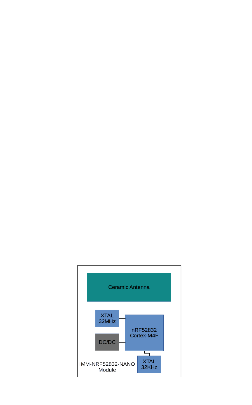
The nRF52832 is an ultra low power System on Chip (SoC) from Nordic Semiconductor. It
integrates the nRF52 series 2.4GHz transceiver, a 32 bits ARM® Cortextm-M4F MCU, Flash
memory, analog and digital I/O. The nRF52832 supports Bluetooth 5 Low Energy.
The IMM-NRF52832-NANO is a 10 x 7 x 1.6 mm module with embedded ceramic antenna. It
allows developers to take full advantage of the nRF52832 by making all its I/O available via 34
SMD 0.5mm pitch pads.
Features:
32 bits ARM® Cortextm-M4F @ 64MHz.
2.4GHz transceiver, Bluetooth 5 LE
64KB SRAM.
512KB Flash
32 MHz Crystal 25PPM
32.768 KHz Crystal 20PPM
DC/DC power mode configuration
30 configurable I/O pins
Type 2 NFC-A Tag with wakeup on field
8 configurable 12 bits, 200 ksps ADC
Digital microphone interface
3 x 4 channels PWM
AES hardware encryption
RNG, RTC
Temperature sensor
Up to 4 PWM
Digital interfaces SPI Master/Slave, 2-wire Master (I2C compatible), UART
(CTS/RTS)
Quadrature decoder
Low power comparator
Operating voltage : 1.8V to 3.6V
Dimension : 10 x 7 x 1.6 mm
FCC & CE certified
Updated Jan. 2018 Page 1
IMM-NRF52832-NANO module
Module Layout
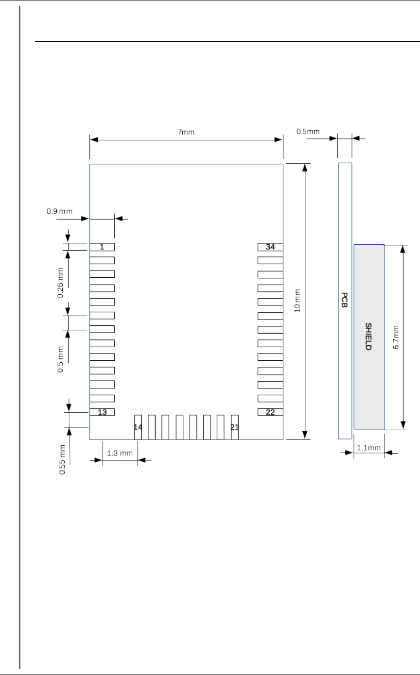
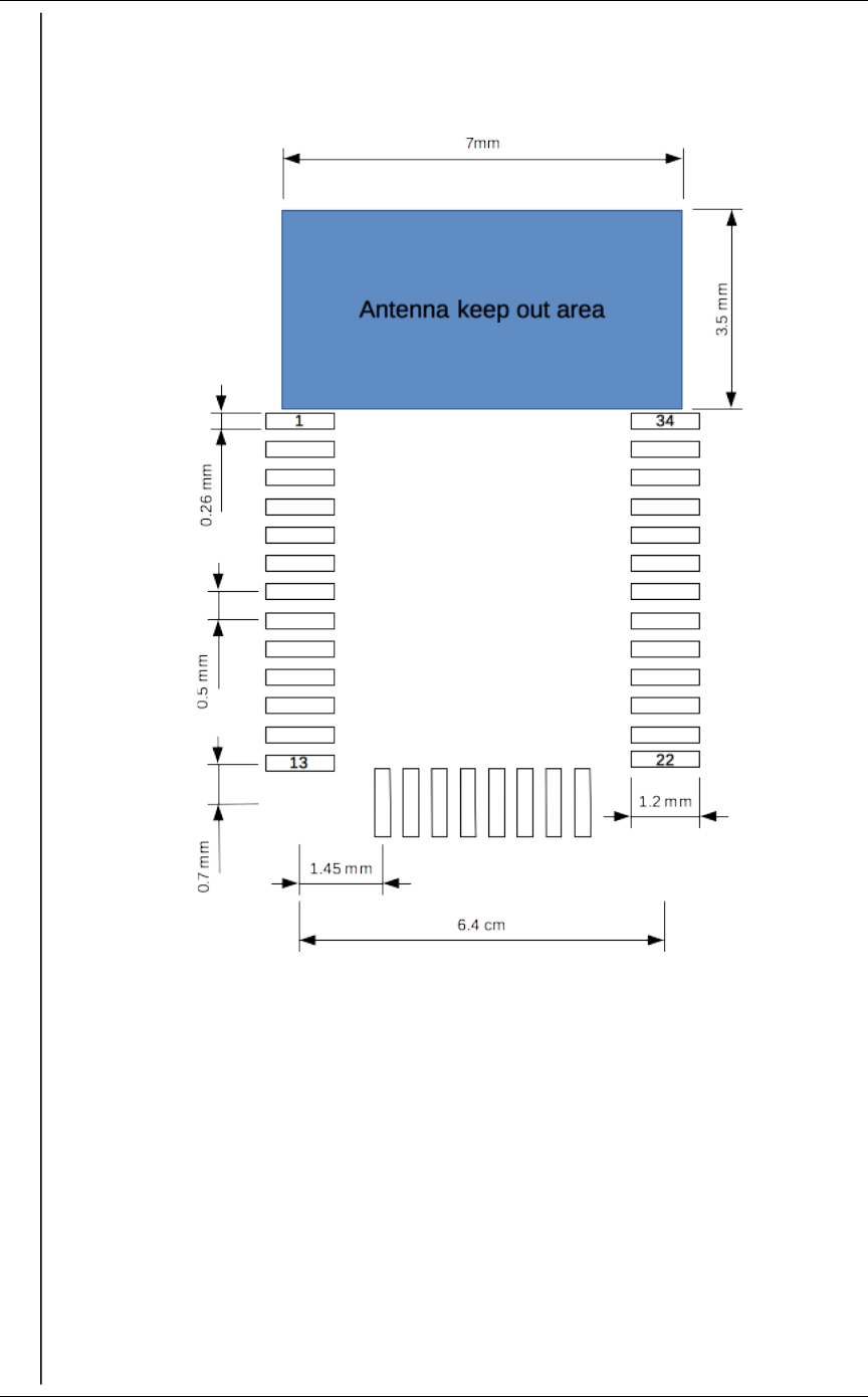
Dimensions and I/O pins layout
Bellow is the direct relationship of the module pads and the nRF52832 I/O pins.
Updated Jan. 2018 Page 2
Fig. 1: Dimensions top view
IMM-NRF52832-NANO module
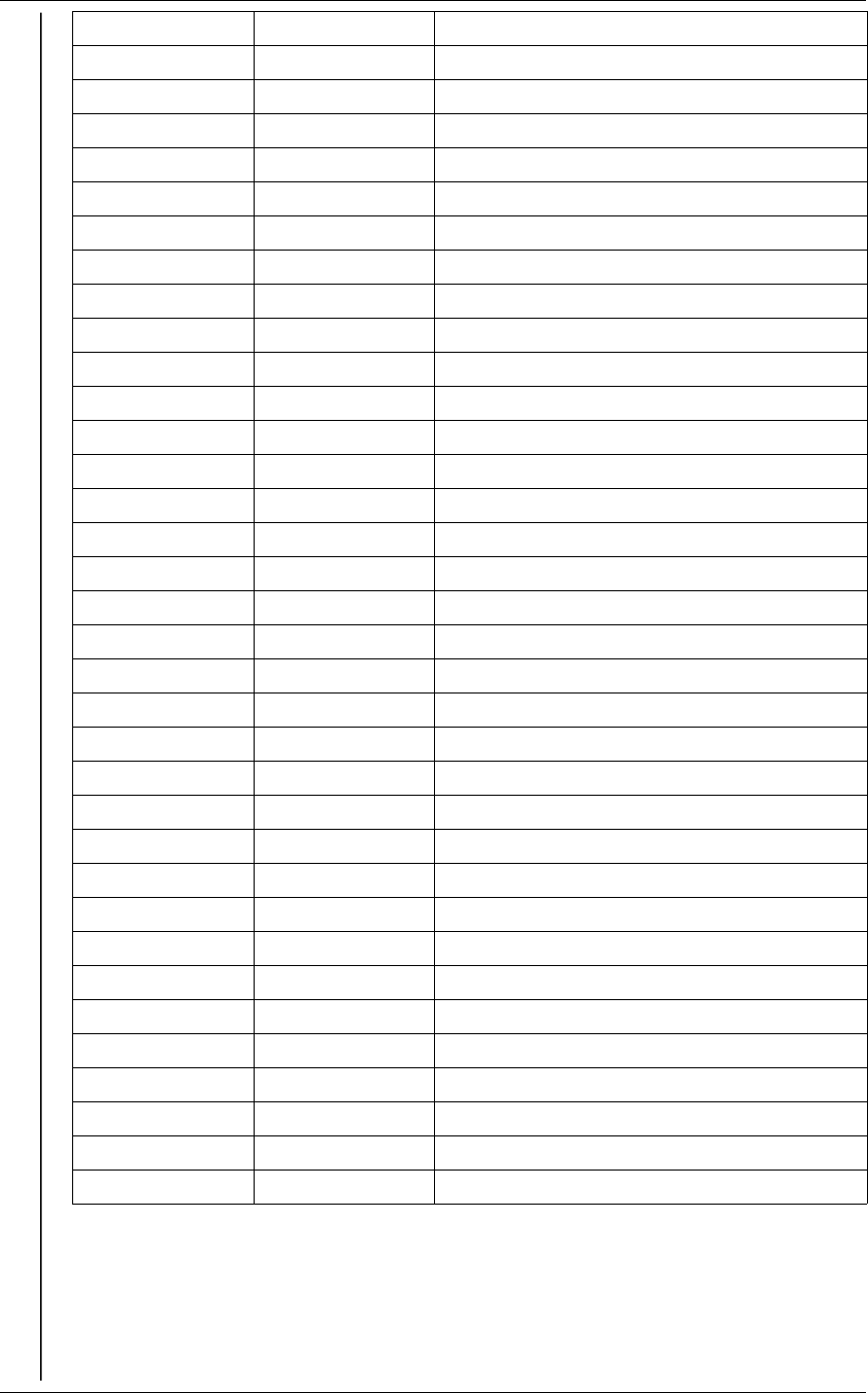
Pin Number Pin Name Description
1 P0.22 GPIO 22
2 P0.21/nRESET GPIO 21 or RESET active low
3 P0.20 GPIO 20
4 P0.19 GPIO 19
5 P0.18 GPIO 18
6 P0.17 GPIO 17
7 P0.16 GPIO 16
8 P0.15 GPIO 15
9 P0.14 GPIO 14
10 P0.13 GPIO 13
11 P0.12 GPIO 12
12 P0.11 GPIO 11
13 P0.10/NFC2 GPIO 10 or NFC2 tag
14 P0.09/NFC1 GPIO 9 or NFC1 tag
15 P0.08 GPIO 8
16 P0.07 GPIO 7
17 P0.06 GPIO 6
18 SWDIO JTAG Data
19 SWDCLK JTAG Clock
20 VDD Power 1.8V-3.6V
21 GND Ground
22 P0.05/AIN3 GPIO 5 or Analog Input 3
23 P0.04/AIN2 GPIO 4 or Analog Input 2
24 P0.03/AIN1 GPIO 3 or Analog Input 1
25 P0.02/AIN0 GPIO 2 or Analog Input 0
26 P0.31/AIN7 GPIO 31 or Analog Input 7
27 P0.30/AIN6 GPIO 30 or Analog Input 6
28 P0.29/AIN5 GPIO 29 or Analog Input 5
29 P0.28/AIN4 GPIO 28 or Analog Input 4
30 P0.27 GPIO 27
31 P0.26 GPIO 26
32 P0.25 GPIO 25
33 P0.24 GPIO 24
34 P0.23 GPIO 23
Updated Jan. 2018 Page 3
IMM-NRF52832-NANO module
SMD Footprint
Note : Do not route any traces or planes under the indicated antenna area.
Updated Jan. 2018 Page 4
Fig. 2: SMD footprint top view
IMM-NRF52832-NANO module
Quick Start
Requirements
The follows are required for software development
•Debug J-Tag : IDAP-Link, Segger J-Link, or any ARM compatible J-Tag.
•Nordic SDK & Softdevice BLE stack (https://developer.nordicsemi.com/)
•C/C++ embedded software development environment : Eclipse, Keil, CrossWorks, ...
Flashing firmware
The Nordic Softdevice is required to use BLE application. There are many methods to flash it in
the module. The official method from Nordic is to use nRFGo with J-Link. This program is
available only on Windows operating system. The other method is to use IDAP-Link with
IDAPnRFProg for OSX & Windows. More details available on blog page
http://embeddedsoftdev.blogspot.ca/p/ehal-nrf51.html. The IDAPnRFProg can program
Softdevice, DFU and Firmware app without requiring mergehex. It can parallel program multiple
nRF51 boards at once when multiple IDAP-Link are connected to PC..
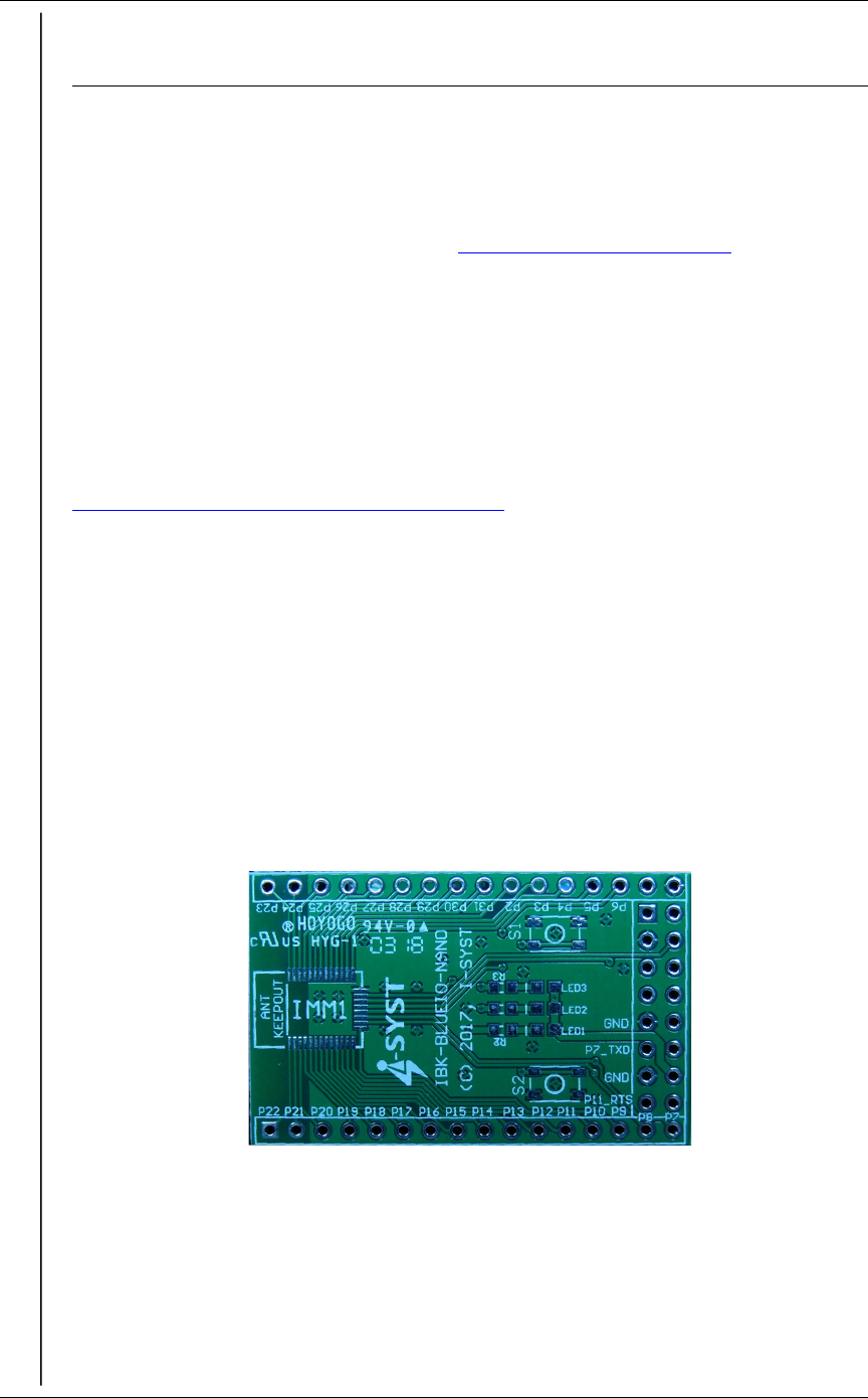
Breakout board
The module can also be mounted on the optional breakout board, the IBK-BLUEIO-NANO. This
breakout board has all I/O pins routed out to standard DIP32, 2.54mm pitch header pin, with
onboard LED indicator and coin battery holder. Ready to be mounted on a breadboard. The SWD
pins are also routed out for debug probe. Connect it to the IDAP-Link for OpenOCD debugging
or turn the IMM-NRF52832-NANO into mBed compatible.
Updated Jan. 2018 Page 5
Fig. 3: IBK-BLUEIO-NANO.
Breakout PCB for the IMM-NRF52832-
NANO module
IMM-NRF52832-NANO module
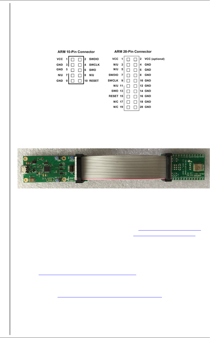
J-Tag wiring
The IMM-NRF52832-NANO module has exposed the SWD (Serial Wire Debug) pins SWDIO &
SWCLK, see I/O layout section. The module can be directly connected to a J-Tag tool for
development by wiring the 2 SWD and the optional Reset pins to the appropriate pins on the J-Tag
connector. The VIN must be wire to the VCC pin on the J-Tag. GND pad is also require to be
connected to GND on J-Tag.
The module can be powered from 1.8V to 3.6V on VIN. It could be coin battery or DC supply
source.
Nordic Software
The Nordic SDK and software tools can be download from http://developer.nordicsemi.com and
http://www.nordicsemi.com. Community support forum at https://devzone.nordicsemi.com.
Eclipse IDE
Eclipse with GCC is the most cost effective software development environment. It is 100% free.
The drawback is that it requires a bit of gymnastics to setup. Fortunately many Blog posts are
available on the Internet showing step by step. Follow this blog to setup the Eclipse IDE & GCC
compiler: http://embeddedsoftdev.blogspot.ca/p/eclipse.html.
There are samples code in the Nordic SDK itself. Other Eclipse based example code are available
from this Blog page http://embeddedsoftdev.blogspot.ca/p/ehal-nrf51.html
Updated Jan. 2018 Page 6
Fig. 4: ARM JTAGE Connector
Fig. 5: IDAP-Link JTag with IBK-BLUEIO-NANO for development with the
IMM-NRF52832-NANO module
FCC Warning
This device complies with part 15 of the FCC Rules. Operation is subject to the following two
conditions: (1) This device may not cause harmful interference, and (2) this device must accept
any interference received, including interference that may cause undesired operation.
Any changes or modifications to this unit not expressly approved by the party responsible for
compliance could void the user's authority to operate the equipment.
FCC Radiation Exposure Statement:
This equipment complies with FCC radiation exposure limits set forth for an uncontrolled
environment. End users must follow the specific operating instructions for satisfying RF
exposure compliance.
Note 1: This module certified that complies with RF exposure requirement under portable or
mobile or fixed condition, this module is to be installed only in portable or mobile or fixed
applications.
A portable device is defined as a transmitting device designed to be used so that the radiating
structure(s) of the device is/are within 20 centimeters of the body of the user
A mobile device is defined as a transmitting device designed to be used in other than fixed
locations and to generally be used in such a way that a separation distance of at least 20
centimeters is normally maintained between the transmitter's radiating structure(s) and the
body of the user or nearby persons. Transmitting devices designed to be used by consumers or
workers that can be easily re-located, such as wireless devices associated with a personal
computer, are considered to be mobile devices if they meet the 20 centimeter separation
requirement.
A fixed device is defined as a device is physically secured at one location and is not able to be
easily moved to another location.
Note 2: Any modifications made to the module will void the Grant of Certification, this module
is limited to OEM installation only and must not be sold to end-users, end-user has no manual
instructions to remove or install the device, only software or operating procedure shall be
placed in the end-user operating manual of final products.

Note 3: The device must not transmit simultaneously with any other antenna or transmitter.
Note 4: To ensure compliance with all non-transmitter functions the host manufacturer is
responsible for ensuring compliance with the module(s) installed and fully operational. For
example, if a host was previously authorized as an unintentional radiator under the Declaration
of Conformity procedure without a transmitter certified module and a module is added, the
host manufacturer is responsible for ensuring that the after the module is installed and
operational the host continues to be compliant with the Part 15B unintentional radiator
requirements. Since this may depend on the details of how the module is integrated with the
host, I-SYST Inc. shall provide guidance to the host manufacturer for compliance with the Part
15B requirements.
The OEM integrator is still responsible for the FCC compliance requirement of the end product,
which integrates this module. Appropriate measurements (e.g. 15 B compliance, 15C
intentional emissions (Fundamental + Out-of-Band Emission)) and if applicable additional
equipment authorizations (e.g. Verification , DoC) of the host device to be addressed by the
integrator/manufacturer.
Note 5: FCC ID label on the final system must be labeled with “Contains FCC ID: 2ALTY-
52832NANO” or “Contains transmitter module FCC ID: 2ALTY-52832NANO”.
The transmitter module must be installed and used in strict accordance with the manufacturer's
instructions as described in the user documentation that comes with the host product. I-SYST
Inc. is responsible for the compliance of the module in all final hosts.