IBA Molecular N A FDG000001 Multi-Purpose Synthesis System User Manual
IBA Molecular N. A. Multi-Purpose Synthesis System
User Manual

Synthera ®
User Manual
FDG000130 | November 2006 | 1 |
SYNTHERA ™ USER MANUAL
FDG000130 11/17/2006 Rev.: 1 Pg. 2 of 60
Change Record
Revision A B C D 1
ECO No. N/A N/a N/A 015 027
Date 05/05/06 05/19/06 07/24/06 11/08/06
Rev. Description of Change
A Initial release
B Updated
C Style guide applied
D CE Update #1
1 CE Update #2 (New Control Panel & RFID) and Full Release
IBA Molecular | Apr 06 Direction: MANXXXX © IBA/All Rights Reserved

SYNTHERA ™ USER MANUAL
FDG000130 11/17/2006 Rev.: 1 Pg. 3 of 60
1 Table of contents
1 Table of contents............................................................................................................................................................. 3
2 Introduction...................................................................................................................................................................... 6
3 Safety............................................................................................................................................................................... 6
3.1 Warning labels.......................................................................................................................................................... 6
3.2 FCC Regulatory Guidance....................................................................................................................................... 7
3.3 General..................................................................................................................................................................... 7
3.4 Radiation safety considerations ............................................................................................................................... 7
3.5 Poisonous gases...................................................................................................................................................... 7
3.6 Fire hazard ............................................................................................................................................................... 7
3.7 Injury hazard............................................................................................................................................................. 7
3.8 Dangerous chemicals............................................................................................................................................... 8
3.9 Electrical safety ........................................................................................................................................................ 8
3.10 General Recommended Safety Practices ............................................................................................................ 8
3.11 Accidents and emergency procedures ................................................................................................................. 8
4 Overview.......................................................................................................................................................................... 9
4.1 General System Specifications ................................................................................................................................9
4.1.1 Controls........................................................................................................................................................... 11
4.1.2 Installation Requirements ...............................................................................................................................12
4.1.3 Air/Gas Utilities................................................................................................................................................ 12
4.1.4 User interface.................................................................................................................................................. 12
5 General Operating Instructions ..................................................................................................................................... 14
5.1 IFP ™ installation (See Fig. 5) ............................................................................................................................... 14
5.2 Inert gas pressure adjustment................................................................................................................................15
5.3 Gas flow rate adjustment ....................................................................................................................................... 15
5.4 IFP ™ Ejection ....................................................................................................................................................... 15
5.5 Power Shutdown .................................................................................................................................................... 16
5.6 Replacement of Consumable Materials ................................................................................................................. 18
6 Software......................................................................................................................................................................... 18
6.1 Safeguards............................................................................................................................................................. 18
6.2 Access control........................................................................................................................................................ 19
6.3 Executable files and libraries (folder C:\MPB\sets)................................................................................................ 19
IBA Molecular | Apr 06 Direction: MANXXXX © IBA/All Rights Reserved

SYNTHERA ™ USER MANUAL
FDG000130 11/17/2006 Rev.: 1 Pg. 4 of 60
6.4 Method definition file (folder C:\MPB\METHODS) ................................................................................................. 20
6.5 Bitmap files (folder C:\MPB\BITMAPS).................................................................................................................. 20
6.6 Communication parameters file ............................................................................................................................. 21
6.7 Definition table file.................................................................................................................................................. 22
6.7.1 Digital Indicator ............................................................................................................................................... 22
6.7.2 Analog Indicator .............................................................................................................................................. 22
6.7.3 Digital Signal ................................................................................................................................................... 23
6.7.4 Analog Signal.................................................................................................................................................. 23
6.8 Script files............................................................................................................................................................... 25
6.9 Plot parameters file ................................................................................................................................................ 25
6.10 Log and report files............................................................................................................................................. 26
6.11 Starting the application....................................................................................................................................... 26
6.11.1 User Login....................................................................................................................................................... 26
6.11.2 Main Screen.................................................................................................................................................... 27
6.11.3 Menu items...................................................................................................................................................... 28
6.12 Create new Methods, Scripts, Parameters......................................................................................................... 35
6.12.1 Create New Communication Settings............................................................................................................. 35
6.12.2 Create New Method........................................................................................................................................ 36
6.12.3 Create New Script........................................................................................................................................... 36
6.12.4 Create New Signal Definition file .................................................................................................................... 36
6.12.5 Create New Graph settings............................................................................................................................. 36
6.12.6 Create New Bitmap......................................................................................................................................... 37
6.13 Errors and trouble-shootings .............................................................................................................................. 37
6.13.1 User Login....................................................................................................................................................... 37
6.13.2 Method file errors ............................................................................................................................................ 37
6.13.3 Errors in Signal Definition file.......................................................................................................................... 38
6.13.4 Script Errors .................................................................................................................................................... 43
6.13.5 View Report file............................................................................................................................................... 45
7 User maintenance ......................................................................................................................................................... 47
7.1 Cleaning and decontamination...............................................................................................................................47
8 Applications ................................................................................................................................................................... 48
8.1 F-18 FDG ............................................................................................................................................................... 48
IBA Molecular | Apr 06 Direction: MANXXXX © IBA/All Rights Reserved

SYNTHERA ™ USER MANUAL
FDG000130 11/17/2006 Rev.: 1 Pg. 5 of 60
8.1.1 Disclaimer ....................................................................................................................................................... 48
8.1.2 FDG Product Specifications............................................................................................................................ 48
8.1.3 Materials and supplies .................................................................................................................................... 48
8.1.4 General Description of Synthesis Procedure.................................................................................................. 54
8.1.5 Operator’s instructions.................................................................................................................................... 57
IBA Molecular | Apr 06 Direction: MANXXXX © IBA/All Rights Reserved
SYNTHERA ™ USER MANUAL
FDG000130 11/17/2006 Rev.: 1 Pg. 6 of 60
2 Introduction
This User Manual provides reference information, operation, and maintenance instructions for using the Synthera ®
Processing System. The document contains proprietary information and no part may be reproduced, translated, or
transmitted without express written permission of:
Ion Beam Applications S.A.
Chemin du Cyclotron, 3
B-1348 Loavain-la-Neuve, Belgium
Manufactured by:
IBA Molecular North America.
100 Executive Dr Suite 100 Sterling VA 20166.
Tel + 1 703 787 7900
Fax + 1 703 787 4079
Please direct all questions regarding equipment safety or operation to IBA Customer Service at:
Phone – IBA Customer Support +32 10 47 58 31
Phone - IBA Main Switch Board +32 10 47 58 11
Fax – IBA Customer Support +32 10 47 59 00
E-mail customer_support@iba.be
Contents of this manual have been carefully checked for accuracy and agreement with the
hardware and/or software described. Since deviations cannot be precluded entirely IBA cannot
guarantee complete agreement and is not liable for incidental or consequential damages in
connection with use of this manual.
3 Safety
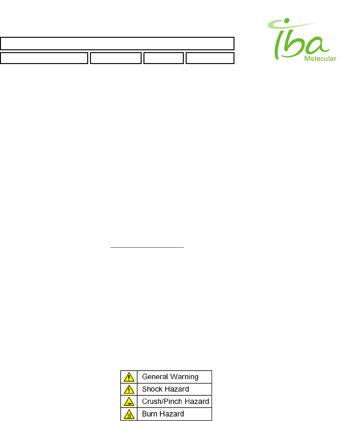
3.1 Warning labels
The following labels are used on this product and throughout the manual to alert user to various hazards:
IBA Molecular | Apr 06 Direction: MANXXXX © IBA/All Rights Reserved

SYNTHERA ™ USER MANUAL
FDG000130 11/17/2006 Rev.: 1 Pg. 7 of 60
3.2 FCC Regulatory Guidance
This device has been tested for compliance and certified under FCC Part 15. Any changes or modifications to the unit not
expressly approved by IBA Molecular may void the user’s authority to operate the equipment.
Antennas: Use only the supplied or an approved replacement antenna. Unauthorized antennas, modifications, or
attachments could cause damage and may violate regulations.
3.3 General
Users of this equipment are expected to read, understand, and adhere to all instructions and safety warnings posted
within this manual. In addition, user of this equipment shall agree to the following:
This equipment shall be operated only by properly qualified personnel
This equipment shall be operated according to applicable safety regulations.
User shall use only IBA approved materials and supplies as described in this manual
NOTE: ALWAYS FOLLOW INSTRUCTIONS PROVIDED IN THIS MANUAL AND OTHER
MANUFACTURER DOCUMENTATION. THIS EQUIPMENT MAY CAUSE SEVERE INJURY AND
PROPERTY DAMAGE IF USED IMPROPERLY.
3.4 Radiation safety considerations
Synthera® system is intended for processing radioactive materials. Processing module with associated plumbing and
fluid processing parts must be adequately shielded, preferably housed within a hot cell. Radiation safety requirements
may vary from site to site. Compliance with appropriate local regulations is responsibility of the user.
3.5 Poisonous gases
No poisonous gases are used In Synthera® unless specified in applications section.
3.6 Fire hazard
Flammable liquids may be used in some processing and cleaning applications. Generally the following flammable liquids
are used:
Ethyl Alcohol
Auto Ignition Temperature: 360ºC.
Flashpoint Temperature: 14ºC.
Important Note: For safety purposes, the maximum operating temperature of the Synthera Processing Unit is limited to
250º C. Always turn the heater off, remove all power and allow unit to cool off for a minimum of 10 minutes before
cleaning or disinfecting; especially when using Ethyl Alcohol or any other flammable solvent.
3.7 Injury hazard
The Synthera® unit includes a pneumatically operated IFP™ holder mechanism that moves automatically when
performing installation and ejection operations. In order to prevent severe injury to extremities, pay attention to all warning
symbols and keep hands clear of IFP™ holder when installation and ejection processes are in progress.
IBA Molecular | Apr 06 Direction: MANXXXX © IBA/All Rights Reserved

SYNTHERA ™ USER MANUAL
FDG000130 11/17/2006 Rev.: 1 Pg. 8 of 60
3.8 Dangerous chemicals
Synthera® may be used in conjunction with dangerous chemicals and solvents specific to application. Refer to
applications section of this manual for specific dangerous chemicals use.
3.9 Electrical safety
This system uses hazardous electrical voltage. Never remove covers and defer all servicing activities to qualified
personnel.
3.10 General Recommended Safety Practices
Always wear a personal dose monitor with intensity alarm.
No smoking or eating in the Radiochemistry Lab.
Do not use refrigerators for food or radioactive material.
Never pipette by mouth.
Use gloves and laboratory coat.
Work with radioactive material only in the hot cell.
Work on surfaces lined with adsorbent paper.
Utilize shielding and distance whenever possible.
Follow the recommended disposal procedure for solid and liquid radioactive waste
Monitor work areas if there is any uncertainty regarding the radioactivity.
Wash your hands thoroughly after finished work.
Report accidental inhalation, ingestion, injury or spills to the responsible engineer.
3.11 Accidents and emergency procedures
In the event of a radiation accident, all personnel must observe the applicable national and local laws and regulations.
In the event of an accident involving personal injury, seek urgent medical attention at once. In case of fire evacuate the
premises. Respect your local emergency procedures regarding the use of fire extinguishers, evacuation and turning off
equipment.
If your procedure permits/requires that you turn off the equipment:
Press the POWER OFF switch.
Remove AC cords from in-line power supplies
Shut off compressed air and gases
It is not necessary to eject IFP™
IBA Molecular | Apr 06 Direction: MANXXXX © IBA/All Rights Reserved
SYNTHERA ™ USER MANUAL
FDG000130 11/17/2006 Rev.: 1 Pg. 9 of 60
4 Overview
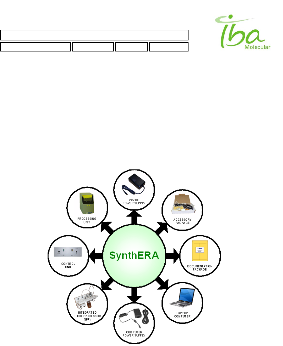
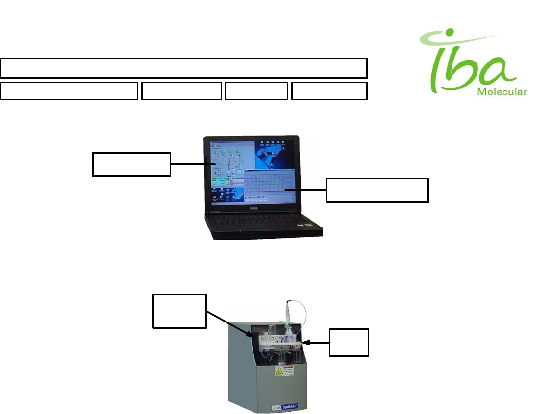
Synthera ® is a multi-purpose synthesis system (See Figure 1), which automates the synthesis of radiopharmaceuticals.
4.1 General System Specifications
The system includes:
• Processing Unit • 24VDC Power Supply
• Control Unit • Documentation Package
• Laptop PC & Power Supply • Accessory Package
(software, cables, manuals)
Figure 1
IBA Molecular | Apr 06 Direction: MANXXXX © IBA/All Rights Reserved

SYNTHERA ™ USER MANUAL
FDG000130 11/17/2006 Rev.: 1 Pg. 10 of 60
TECHNICAL SPECIFICATIONS
Power Requirements (Processing Unit): Voltage: 24VDC
Amps: 4
Power: 100 Watts Max.
Fuse Rating: 5A F/B
Power Requirements (Control Unit): Voltage: 110/230 VAC
Frequency: 50Hz-60Hz
Amps: .5
Power: 50 Watts
Fuse Rating: 1A F/B
Operating Environment: Temperature: 50º to 95º F (10º to 35º C)
Humidity: 20% to 85% Relative Humidity (Non-Condensing)
Storage Environment (Within Case): Temperature: 0º to 140º F (-18º to 60º C)
Humidity: 20% to 85% Relative Humidity (Non-Condensing)
Dimensions Processing Unit (WxDxH): 6.25" x 12.00" x 11.00"
(15.9cm x 30.4cm x 27.9cm)
Control Unit (WxDxH): 7.25" x 5.00" x 4.50"
(18.4cm x 12.7cm x 11.4cm)
Laptop PC (WxDxH): 13.00" x 10.50" x 1.75"
(33.0cm x 26.7cm x 4.4cm)
Weight Control Unit: 5 lbs (1.8 kg)
Processing Unit: 18 lbs (8.2 kg)
Laptop PC: 6.4lbs (2.9 kg)
Total Shipping Weight: 68lbs (30.8 kg)
Certifications CE
IBA Molecular | Apr 06 Direction: MANXXXX © IBA/All Rights Reserved
SYNTHERA ™ USER MANUAL
FDG000130 11/17/2006 Rev.: 1 Pg. 11 of 60
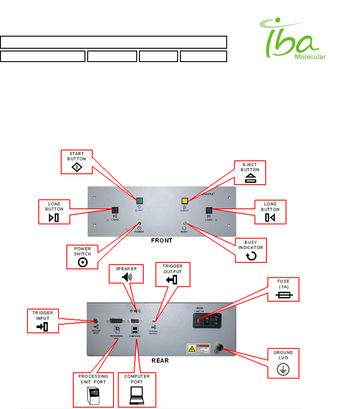
4.1.1 Controls
All controls are located on Control Box, which is separate from processing unit and must be installed outside of the
shielded enclosure and an area easily accessible to the operator.
Control Box power switch is located on the bottom side of the control box (when it is mounted on a vertical surface).
Refer to Figure 2:
Figure 2
IBA Molecular | Apr 06 Direction: MANXXXX © IBA/All Rights Reserved

SYNTHERA ™ USER MANUAL
FDG000130 11/17/2006 Rev.: 1 Pg. 12 of 60
Next to the power switch is the AC voltage selector fuse holder. Be sure it is set to correct AC line voltage before turning
the system on.
NOTE: LAPTOP PC AND PROCESSING UNIT POWER IS SUPPLIED THROUGH SEPARATE IN-
LINE POWER SUPPLIES NOT EQUIPPED WITH POWER SWITCHES. TO COMPLETELY REMOVE
POWER FROM ALL UNITS TURN OFF POWER SWITCH ON CONTROL BOX, THEN REMOVE AC
POWER CABLE FROM THE IN-LINE POWER SUPPLY CONNECTED TO PROCESSING UNIT AND
FROM THE LAPTOP POWER SUPPLY. LAPTOP COMPUTER CAN BE OPERATED FOR A SHORT
PERIOD OF TIME WITHOUT AC POWER.
EJECT button located on the front side of the control box is used to eject disposable plumbing element IFP™ (Integrated
Fluidic Processor)
Two LOAD buttons located on opposite sides of the control box are used to load IFP™
POWER Indicator is lit when unit power is on.
BUSY Indicator is lit during IFP™ Installation and ejection operations.
4.1.2 Installation Requirements
Cables distance Synthera® to Control box 10 m. Control box to PC 10 m
Hot cell (minimum size)
For one Synthera ® 18 x 45 x 40 cm (W x D x H)
For two Synthera ® 36 x 45 x 40 cm (W x D x H)
For three Synthera ® 54 x 45 x 40 cm (W x D x H)
If no kit ejection is necessary the depth can be 35 cm
4.1.3 Air/Gas Utilities
Compressed air 7 - 10 bar 4mm O.D. (dried and filtered)
Compressed inert gas 1.05 – 1.20 bar 3mm O.D. He or N2 99.995% purity
Refer to Applications section for Product Specific Performance Specifications and application specific utilities. No
poisonous gases are used in this system unless specified in applications section.
4.1.4 User interface
The Synthera ® System includes a graphical user interface (GUI) and development environment for programming and
monitoring the automated multi purpose module Figure 3. The GUI and development environment are based on graphic
library Qt and operate on a personal computer (PC) that is connected to the Synthera ® processing module(s).
IBA Molecular | Apr 06 Direction: MANXXXX © IBA/All Rights Reserved
SYNTHERA ™ USER MANUAL
FDG000130 11/17/2006 Rev.: 1 Pg. 13 of 60
IBA Molecular | Apr 06 Direction: MANXXXX © IBA/All Rights Reserved
SYNTHERA GUI
(SYSTEM DISPLAY)
SYNTHERA GUI
(PROCESS MONITORING)
Figure 3
Radiotracer production takes place entirely within the disposable Integrated Fluid Processor (IFP™). The IFP™ along with
the reagents and vials is attached to the Actuator Module (AM) during the synthesis operation.
FDG KIT
(IFP)
IFP
HOLDER
Figure 4
While the IFP™ is specifically designed and equipped for each tracer production; the AM is a non-product specific device
that can be used for the production of a variety of products. The Synthera ® System’s plumbing arrangement also insures
complete isolation of fluid paths; which eliminates cross-contamination concerns when working with different products.
The vials for the reagents and solvents used in the IFP™ are typically sealed with Teflon® coated rubber septa. The
reagents are transferred with compressed nitrogen gas through Tefzel® or Polypropylene 1/16” OD tubing attached
directly to the valve stators (typically made of Viton®) and other parts of the system.
The reaction vessel is typically comprised of a:
10 ml borosilicate glass serum vial
Silicone or Viton® rubber septa
20 mm crimp top seal
Temperature of the reaction vessel can be adjusted between 30°C and 200°C. Liquid Nitrogen cooling option is available,
which extends temperature range to -40°C. Pressure and temperature in the reaction vessel as well as the radioactivity in
the reaction vessel and in the product collection container are continuously displayed and recorded during the synthesis
process. Pressure and temperature can be automatically controlled.
With the aid of a PC, the Synthera ® System performs reagent additions, solution mixing, heating operations, etc.
according to a pre-defined sequence (script). The unit requires minimal operator interaction during the synthesis process.
The principal benefits of the unit are process reliability and elimination of hazards associated with radiation exposure.
SYNTHERA ™ USER MANUAL
FDG000130 11/17/2006 Rev.: 1 Pg. 14 of 60
The final product can be delivered via stationary plumbing attached to the back of the processing unit (AM) or through a
disposable tube attached to the IFP™ depending upon the application. Multiple modules can also be connected in series
to accomplish multi-step synthesis.
5 General Operating Instructions
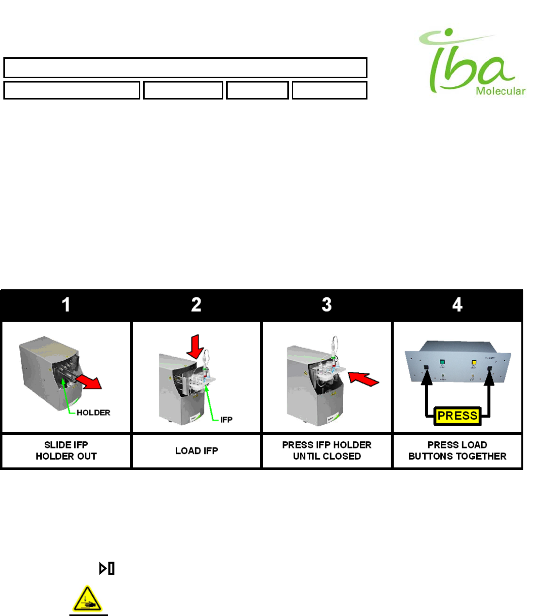
5.1 IFP ™ installation (See Fig. 5)
To Install IFP™:
Make sure compressed air and inert gas are connected to the processing unit
Power up the processing unit and PC. It is not necessary to start PC software to install the kit
Figure 5.
Pull IFP™ holder forward to clear the cover as shown in Step 1 on Figure 5. . If the holder will not move press
EJECT button on Control Box. Stand clear of the processing unit to allow the IFP™ holder to move to EJECT
position.
Insert IFP™ into the holder as shown in Step 2 on Figure 5.
Push the holder back as far as possible as shown in Step 3 on Figure 5.
Press both LOAD buttons on the control box simultaneously as shown in Step 4 on Figure 5. .
KEEP YOUR HANDS CLEAR OF THE PROCESSING UNIT DURING ENGAGEMENT
PROCESS. DO NOT INTERFERE WITH THE HOLDER MOVEMENT. IFP™ HOLDER IS
RETRACTED WITH A FORCE IN EXCESS OF 100 KG AND MAY CAUSE SEVERE INJURY
IFM™ mounting process takes approximately 10 sec during which time the BUSY indicator light will remain lit and no
PC instructions can be executed. During this time communication with PC may be temporarily interrupted which is
indicated by audible signal from control box speaker. This is normal condition.
IBA Molecular | Apr 06 Direction: MANXXXX © IBA/All Rights Reserved
SYNTHERA ™ USER MANUAL
FDG000130 11/17/2006 Rev.: 1 Pg. 15 of 60
5.2 Inert gas pressure adjustment
Inert gas pressure must be within 205-220 kPa. To adjust pressure proceed as follows:
1. Turn on power switch on control box.
2. Start Synthera® control program on PC
3. Install IFP™.
4. Using PC control program set pressure set point to 205 kPa
5. Open V16
6. Open inert gas supply and gradually increase pressure until V14 opens
7. Gradually decrease gas pressure until V14 cycles every 5-10 sec.
8. Set pressure set point to 300 kPa and check the pressure. It must be 205 – 220. Repeat steps 6-7 if
necessary
9. Close V16
5.3 Gas flow rate adjustment
For normal operation of the unit pressure in the reactor must be within 25-35 kPa with V14 and V15 open and pump on.
To adjust flow rate proceed as follows:
1. Turn on power switch on control box.
2. Start Synthera® control program on PC
3. Install IFP™.
4. Using PC control program set pressure set point to 0 kPa
5. Open V15
6. Turn pump ON
7. Adjust needle valve located on top of the back cover to achieve pressure 25-35 kPa
8. Close V15 and turn the pump off
5.4 IFP ™ Ejection
To eject the disposable component make sure the processing unit front is clear of any interfering objects and press
EJECT button.
KEEP YOUR HANDS CLEAR OF THE PROCESSING UNIT DURING EJECTION PROCESS.
DO NOT INTERFERE WITH THE HOLDER MOVEMENT. IFP™ HOLDER IS EJECTED WITH A
FORCE IN EXCESS OF 30 KG AND MAY CAUSE SEVERE INJURY
IBA Molecular | Apr 06 Direction: MANXXXX © IBA/All Rights Reserved
SYNTHERA ™ USER MANUAL
FDG000130 11/17/2006 Rev.: 1 Pg. 16 of 60
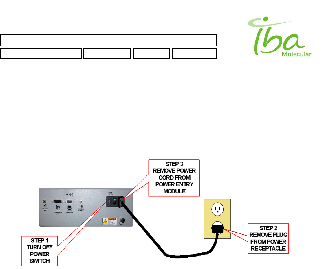
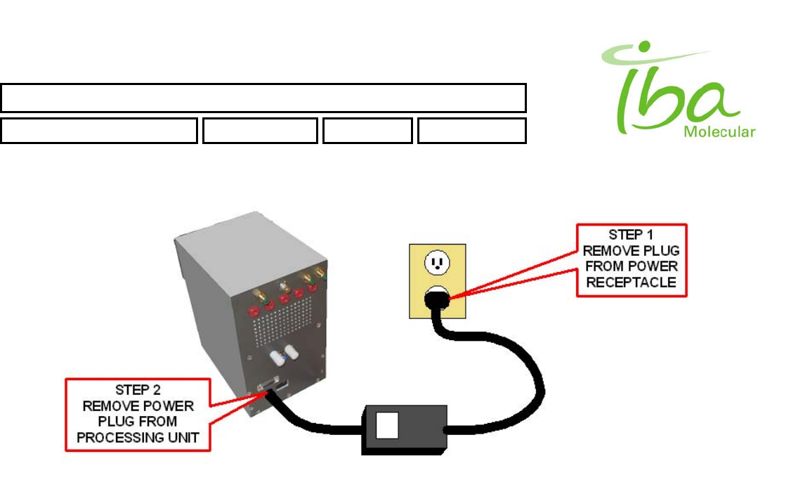
5.5 Power Shutdown
Power shutdown shall be performed in the following manner:
• Control Box:
1. Close Synthera® control program on a PC
2. Turn off power switch on control box.
3. Remove power cord from power receptacle if necessary.
4. Remove power cord from unit if necessary.
• Processing Unit:
1. Disconnect 24V DC power supply cord from electrical receptacle.
2. Remove power connector from rear of processing unit.
IBA Molecular | Apr 06 Direction: MANXXXX © IBA/All Rights Reserved
SYNTHERA ™ USER MANUAL
FDG000130 11/17/2006 Rev.: 1 Pg. 17 of 60
IBA Molecular | Apr 06 Direction: MANXXXX © IBA/All Rights Reserved
SYNTHERA ™ USER MANUAL
FDG000130 11/17/2006 Rev.: 1 Pg. 18 of 60
5.6 Replacement of Consumable Materials
The following consumable items may need periodic replacement:
PART DESCRIPTION IBA PART NO.
Fuse, Fast-Acting, 1A, 250V, 5X20, UL SCD000281
Fuse, Fast-Acting, 5A, 250V, 5X20, UL SCD000286
If replacement parts are required, please contact IBA directly at:
Ion Beam Applications S.A.
Chemin du Cyclotron, 3
B-1348 Loavain-la-Neuve, Belgium
Phone – IBA Customer Support: +32 10 47 58 31
Fax – IBA Customer Support: +32 10 47 59 00
E-mail: customer_support@iba.be
6 Software
In order to provide flexibility needed for programming different processes and hardware configurations, a number of
setting and parameters files are used; all of which can be opened and edited using Notepad or MS Excel. When using
MS Excel be sure to save them as comma separated files. Keep in mind that empty lines in any of the settings files may
result in an error unless they are after the last line. Each line must contain at least one comma. Do not leave spaces at
the beginning of each line.
Names and locations of files are provided and should not be redefined by the user. In any case, the method file must
contain complete and accurate names and relative paths of all setting files used. Names and designations used in all files
are case sensitive. Use relative path notation to address files. All MPB application files are placed in folder C:\MPB and
subfolders.
6.1 Safeguards
The following are some of the safeguards implemented in MS Windows operating system and control software to ensure
safe and reliable operation of the computer:
POST (power On self test). Is performed each time when the PC power is turned on. It includes memory test (parity
check), processor test, video controller test, hard drive, and peripheral devices test.
Parity Check. Each processor operation includes parity check.
Operator Identity Record. Windows software requires operator User ID and password to be entered before logging
on and initiating any automated procedure.
File Access Control. Automated procedure (script) utilized for routine synthesis and other configuration files can be
locked (write protected) to prevent modifications to the program. When program is locked, it may not be changed,
however, operator can still execute the program and perform all other functions necessary for routine production.
IBA Molecular | Apr 06 Direction: MANXXXX © IBA/All Rights Reserved
SYNTHERA ™ USER MANUAL
FDG000130 11/17/2006 Rev.: 1 Pg. 19 of 60
Administrative password is required to change the program.
6.2 Access control
There are three Local User Groups in Windows OS: MPB_Admins, MPB_PowerUsers, MPB_Users.
Members of MPB_Admins group have full control on all MPB application folders and files.
Members of MPB_PowerUsers group can run MPB application, create new Methods, Parameters (Communication
settings, Signal Definition file, Graph settings), Scripts and Bitmaps in appropriate folders (see sections below); but
don't have direct access to LOG, REPORT and USER settings files. LOG, REPORT and USER settings information
accessible only via MPB application.
Members of MPB_Users group can only run MPB application.
No other users have access to MPB application folders and files.
User Groups MPB_User MPB_PowerUser All other
Folders
MPB Read Only Create New NO access
MPB\METHODS Read Only Create New NO access
MPB\PARAMETERS Read Only Create New NO access
MPB\SCRIPTS Read Only Create New NO access
MPB\BITMAPS Read Only Create New NO access
MPB\sets Read Only Read Only NO access
MPB\LOGS NO access NO access NO access
MPB\REPORTS NO access NO access NO access
MPB\users NO access NO access NO access
Table 1 User's Access
6.3 Executable files and libraries (folder C:\MPB\sets)
User interface application is launched by the batch file mpb.bat. This file contains command line instructions to run MPB
application program and is not method or system specific. Application also uses dynamic link libraries included in files
cc3250mt.dll, comm._7.dll, and qtmt335.dll, and additional files: runasspc.exe, crypt.spc.
IBA Molecular | Apr 06 Direction: MANXXXX © IBA/All Rights Reserved

SYNTHERA ™ USER MANUAL
FDG000130 11/17/2006 Rev.: 1 Pg. 20 of 60
6.4 Method definition file (folder C:\MPB\METHODS)
Method definition file contains references to all other settings and parameters files. Use ONLY extension .mtd for method
files. Always place method files in C:\MPB\METHODS folder. Method file is a comma separated text file, containing file
names and comments separated by commas. It always has exactly 5 lines as follows: background picture file name;
communication settings file name; signal definitions file name; script file name and graph settings file name. File names
are case sensitive and MUST include relative path.
The example of FDG.mtd file is provided below:
BITMAPS\FDG_bgr.bmp, background picture file name
PARAMETERS\_comm_set_0.csv, communication data file name
PARAMETERS\FDG_cmd.csv, cmd_indicator file name
SCRIPTS\CLEAN.scr, script file name
PARAMETERS\FDG_graph.csv, graph settings file name
Note that method file is module specific; due to the fact that it defines COM port (in communication data file). If you need
to run the same method in multiple boxes attached to the same PC you will need to create multiple instances of the same
method file. While you may refer to the same script, signal definitions etc., you will need multiple communication settings
files for each box.
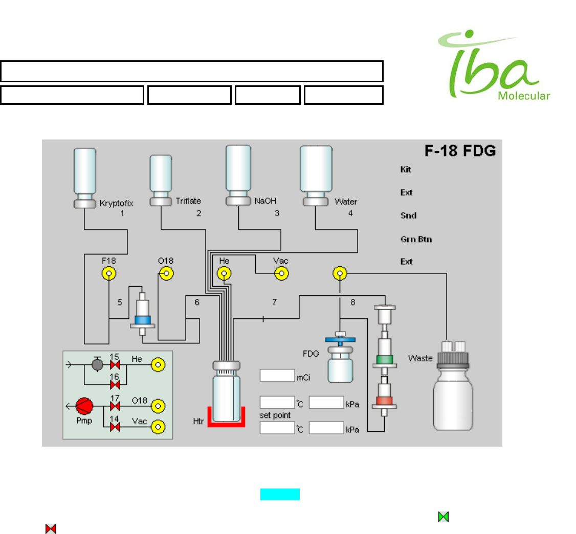
6.5 Bitmap files (folder C:\MPB\BITMAPS)
A bitmap file defines each graphic element used to display system status and to accept user commands in manual mode.
All image files are stored in subfolder “C:\MPB\BITMAPS”. They can be edited using MS Paint or any other graphics
package. Be sure to save them as bitmaps with extension .bmp.
Static graphics is defined by the background bitmap. This file is referenced in line 1 of method definition file (see Method
definition files section above). Use this file to depict plumbing diagram, to show instructions for operator, identify the
process name. Example of this bitmap is shown in Figure 6 below:
IBA Molecular | Apr 06 Direction: MANXXXX © IBA/All Rights Reserved
SYNTHERA ™ USER MANUAL
FDG000130 11/17/2006 Rev.: 1 Pg. 21 of 60
IBA Molecular | Apr 06 Direction: MANXXXX © IBA/All Rights Reserved
Figure 6
This bitmap is always exactly 600x400 pixels.
All dynamic graphic elements are also defined by bitmaps Figure 6. They are displayed according to their signal
definitions and status over the background. These images are designed to reflect changes in feedback and control
signals by changing shapes or colors of various objects. Examples of such dynamic images are: to indicate an open
valve and to indicate closed valve. When both of these images are assigned the same location in the window, only
one of them will be visible creating an illusion of valve changing color when associated control or feedback signal is
changing status.
User may find it necessary to modify bitmap images or create new ones.
6.6 Communication parameters file
This file is referenced in line 2 of method definition file (see Method definition files section above). It defines COM port
number and other communication parameters, such as format of data sent over serial port from PC to Synthera™
processing module and back. User should never modify lines 2 and 3, any changes in format, including number of
commas, will result in loss of communication between PC and processing module. You must however define COM port
number according to your system configuration.
Example of communications file is provided below:
COM1,

SYNTHERA ™ USER MANUAL
FDG000130 11/17/2006 Rev.: 1 Pg. 22 of 60
6.7 Definition table file
This file is referenced in line 3 of method definition file (see Method definition files section above) and contains
assignments of all indicators and signals.
There are four types of objects defined by this file. Feedback data generated within Synthera™ processing unit by
sensors and transmitted to PC via serial connection is defined as “indicators”. Commands generated by PC and
transmitted to processing unit are defined as “signals”. Signals and indicators may be “on-off” type of data, referred to as
“digital”, and transmitted as a single byte (0 or 1), or numeric data referred to as “analog” and transmitted as a word (two
bytes, 16 bits). The following identifiers represent these types of objects:
INP_BIT - digital indicator (state 0, 1), default state – 1 (off);
INP_2BYTES - analog indicator (double);
OUT_BIT - digital signal (state 0, 1), default state – 0 (off);
OUT_2BYTES - analog signal (int);
Each line in definition table file defines one signal or one indicator. This is a comma separated text file, and it must not
include empty lines. Each line must end with a comma, and there should be no unnecessary spaces. The order in which
lines are presented is important. Graphic objects will be displayed in the same order as they are listed in definition file.
Therefore, if objects overlap the object displayed later will obstruct the first object displayed. As a general rule it is best to
avoid overlapping objects, however sometimes they may be useful.
Parameters Byte_n and Bit_n are defined by hardware configuration and firmware of the processing unit. DO NOT modify
these parameters.
Line format for each type of signals and indicators are listed below.
6.7.1 Digital Indicator
INP_BIT x y dx dy Pic_off Pic_on Byte_n Bit_n Name
Type int int int int text text int 0 - 7 text
Notes:
x, y – distance from upper left corner (in pixels)
dx, dy – dimension (in pixels)
Pic_off – file name of bitmap to be displayed when value is 0
Pic_on – file name of bitmap to be displayed when value is 1
Byte_n – byte number in byte sequence received from external device (must not be used by another indicators)
Name – unique indicator name
Example:
INP_BIT,100,200,130,130,error20.bmp,g_check20.bmp,0,0,ind_1,
Restrictions
x < 600, x + dx < 600
y < 400, y + dy < 400
6.7.2 Analog Indicator
INP_2BYTE x y dx dy Byte_n Name Calibr. A Calibr. B Filter
Type Int int int int 0-7 text Double Double Double
Notes:
IBA Molecular | Apr 06 Direction: MANXXXX © IBA/All Rights Reserved

SYNTHERA ™ USER MANUAL
FDG000130 11/17/2006 Rev.: 1 Pg. 23 of 60
x, y – distance from upper left corner (in pixels)
dx, dy – dimension (in pixels)
Byte_n – first byte number in byte sequence received from external device (must not be used by another indicators)
Name – unique indicator name
Calibr. A and Calibr. B – scale and offset for calibration
Filter – averaging constant
Example:
INP_2BYTES,100,350,90,20,7,tempr,0.01,100,
Restrictions
the same as for previous case plus CALIBRATION constants (res = A*x + B) and Filter must be set.
6.7.3 Digital Signal
OUT_BIT x y dx dy Pic_off Pic_on Byte_n Bit_n Name
Type int int int Int text text 0 - 7 text
Notes:
x, y – distance from upper left corner (in pixels)
dx, dy – dimensions (in pixels)
Pic_off – file name of bitmap to be displayed when value is 0
Pic_on – file name of bitmap to be displayed when value is 1
Byte_n – byte number in byte sequence send to external device (must not be used by another signals)
Name – unique indicator name
Example:
OUT_BIT,120,220,25,25,comm_off_off_1.bmp,comm_on_on_1.bmp,2,1,btn_1,
Restrictions
The same as for Digital Indicator
6.7.4 Analog Signal
OUT_2BYTES x y dx dy Calibr. A Calibr. B Byte_n Name
Type int int int int dbl dbl 0-7 text
Notes:
x, y – distance from upper left corner (in pixels)
dx, dy – dimensions (in pixels)
Byte_n – first byte number in byte sequence send to external device (2 bytes must not be used by another signals)
Calibr. A and Calibr. B – scale and offset for calibration
Name – unique signal name
Example:
OUT_2BYTES,100,300,90,20,5,tempr_set,0.01,100,
Restrictions
The same as for Analog Indicator.
IBA Molecular | Apr 06 Direction: MANXXXX © IBA/All Rights Reserved

SYNTHERA ™ USER MANUAL
FDG000130 11/17/2006 Rev.: 1 Pg. 24 of 60
The following is a definitions file used in method FDG.mtd for an illustration:
INP_2BYTES,285,335,44,16,5,Tmp,0.25,0,0.025,
INP_2BYTES,349,335,44,16,3,Prs,1.4,-86,0.05,
INP_2BYTES,285,300,44,16,7,Rad,1,0,0.1,
INP_BIT,75,105,25,13,bitmaps\Valve_LC_O_Top.bmp,bitmaps\Valve_LC_C_Top.bmp,0,0,iV1a,
INP_BIT,75,117,25,13,bitmaps\Valve_LC_C_Bot.bmp,bitmaps\Valve_LC_O_Bot.bmp,0,1,iV1b,
INP_BIT,175,105,25,13,bitmaps\Valve_LC_O_Top.bmp,bitmaps\Valve_LC_C_Top.bmp,0,2,iV2a,
INP_BIT,175,117,25,13,bitmaps\Valve_LC_C_Bot.bmp,bitmaps\Valve_LC_O_Bot.bmp,0,3,iV2b,
INP_BIT,276,105,25,13,bitmaps\Valve_LC_O_Top.bmp,bitmaps\Valve_LC_C_Top.bmp,0,4,iV3a,
INP_BIT,276,117,25,13,bitmaps\Valve_LC_C_Bot.bmp,bitmaps\Valve_LC_O_Bot.bmp,0,5,iV3b,
INP_BIT,376,105,25,13,bitmaps\Valve_LC_O_Top.bmp,bitmaps\Valve_LC_C_Top.bmp,0,6,iV4a,
INP_BIT,376,117,25,13,bitmaps\Valve_LC_C_Bot.bmp,bitmaps\Valve_LC_O_Bot.bmp,0,7,iV4b,
INP_BIT,75,221,25,13,bitmaps\Valve_SC_O_Top.bmp,bitmaps\Valve_SC_C_Top.bmp,1,0,iV5a,
INP_BIT,75,233,25,13,bitmaps\Valve_SC_C_Bot.bmp,bitmaps\Valve_SC_O_Bot.bmp,1,1,iV5b,
INP_BIT,175,221,25,13,bitmaps\Valve_SC_O_Top.bmp,bitmaps\Valve_SC_C_Top.bmp,1,2,iV6a,
INP_BIT,175,233,25,13,bitmaps\Valve_SC_C_Bot.bmp,bitmaps\Valve_SC_O_Bot.bmp,1,3,iV6b,
INP_BIT,276,221,25,13,bitmaps\Valve_LC_O_Top.bmp,bitmaps\Valve_LC_C_Top.bmp,1,4,iV7a,
INP_BIT,276,233,25,13,bitmaps\Valve_LC_C_Bot.bmp,bitmaps\Valve_LC_O_Bot.bmp,1,5,iV7b,
INP_BIT,376,221,25,13,bitmaps\Valve_SC_O_Top.bmp,bitmaps\Valve_SC_C_Top.bmp,1,6,iV8a,
INP_BIT,376,233,25,13,bitmaps\Valve_SC_C_Bot.bmp,bitmaps\Valve_SC_O_Bot.bmp,1,7,iV8b,
INP_BIT,440,30,19,19,bitmaps\ButtonOff.bmp,bitmaps\ButtonOn.bmp,2,2,KitIn,
INP_BIT,440,120,19,19,bitmaps\ButtonOff.bmp,bitmaps\ButtonOn.bmp,2,3,GrnBtn,
INP_BIT,89,368,13,13,bitmaps\Vgr.bmp,bitmaps\Vrd.bmp,2,4,V14,
OUT_BIT,63,93,9,9,bitmaps\Vbr.bmp,bitmaps\Vbg.bmp,2,0,V01,
OUT_BIT,163,93,9,9,bitmaps\Vbr.bmp,bitmaps\Vbg.bmp,2,1,V02,
OUT_BIT,264,93,9,9,bitmaps\Vbr.bmp,bitmaps\Vbg.bmp,2,2,V03,
OUT_BIT,364,93,9,9,bitmaps\Vbr.bmp,bitmaps\Vbg.bmp,2,3,V04,
OUT_BIT,63,209,9,9,bitmaps\Vbr.bmp,bitmaps\Vbg.bmp,2,4,V05,
OUT_BIT,163,209,9,9,bitmaps\Vbr.bmp,bitmaps\Vbg.bmp,2,5,V06,
OUT_BIT,264,209,9,9,bitmaps\Vbr.bmp,bitmaps\Vbg.bmp,2,6,V07,
OUT_BIT,364,209,9,9,bitmaps\Vbr.bmp,bitmaps\Vbg.bmp,2,7,V08,
OUT_BIT,89,287,13,13,bitmaps\Vrd.bmp,bitmaps\Vgr.bmp,3,6,V15,
OUT_BIT,89,313,13,13,bitmaps\Vrd.bmp,bitmaps\Vgr.bmp,3,7,V16,
OUT_BIT,89,341,13,13,bitmaps\Vrd.bmp,bitmaps\Vgr.bmp,4,0,V17,
OUT_BIT,44,336,22,22,bitmaps\Prd.bmp,bitmaps\Pgr.bmp,4,1,Pmp,
OUT_BIT,216,348,50,50,bitmaps\Hdn.bmp,bitmaps\Hup.bmp,3,0,Htr,
OUT_BIT,440,60,19,19,bitmaps\ButtonOff.bmp,bitmaps\ButtonOn.bmp,3,1,Ext,
OUT_BIT,440,90,19,19,bitmaps\ButtonOff.bmp,bitmaps\ButtonOn.bmp,4,4,Snd,
OUT_BIT,440,150,19,19,bitmaps\ButtonOff.bmp,bitmaps\ButtonOn.bmp,4,5,GrnLed,
OUT_2BYTES,285,368,44,16,5,Tmp,1,0,,
OUT_2BYTES,349,368,44,16,7,Prs,0.714,61.429,,
IBA Molecular | Apr 06 Direction: MANXXXX © IBA/All Rights Reserved
SYNTHERA ™ USER MANUAL
FDG000130 11/17/2006 Rev.: 1 Pg. 25 of 60
6.8 Script files
This file is referenced in line 4 of method definition file (see Method definition files section above) and contains timed
sequence of commands for automated processing. Generally, there may be more than one script associated with the
same method. For example cleaning process and synthesis process. The script referenced in method definition will be
loaded as default. It is possible to open another script without changing any of the other settings by clicking button
or selecting File-Load Script from the menu.
Script files uses signal and indicator names assigned in definition table (see above). Note that names are case sensitive
and may not contain commas and spaces. All signal names and all indicator names must be unique. However it is
allowed to have signal with the same name as an indicator.
There are nine types of commands used in a script file:
ID – Compare digital input channel with argument a. Argument b not used
SD – Set digital output to value of argument a. Argument b not used
IA – Check if value of analog input is greater than a and less than b
SA – Assign value of argument a to analog output. Argument b not used
GT – Go to line in script with number a. Argument b not used
WD – wait until digital input is in state a
WA – wait until analog input channel value is between a and b
PD – write in Report file state of digital input
PA – write in Report file value of analog input channel
Script line data types:
Cmd_n Time Cmd Signal name a b Description
int int ID Valid dig inp 0 or 1 ignored Text (not required)
int int SD Valid dig out 0 or 1 ignored Text (not required)
int int IA Valid an inp double double Text (not required)
int int SA Valid an out 0-65535 ignored Text (not required)
int int GT ignored 0-N ignored Text (not required)
int int WD Valid dig inp 0 or 1 ignored Text (not required)
int int WA Valid an inp double double Text (not required)
int int PD Valid dig inp 0 or 1 ignored Text (not required)
int int PA Valid an inp double double Text (not required)
Note: Time value should not be negative (Time >= 0)
Description text can be used as a comment line.
6.9 Plot parameters file
This file is referenced in line 5 of method definition file (see Method definition files section above) and contains settings for
the plot.
Graph settings line data types:
Cmd Signal name Scale Type Color Type Ymin Ymax R G B
cmd Valid name AUTO AUTO ignored ignored ignored ignored ignored
cmd Valid name USER AUTO double double ignored ignored ignored
cmd Valid name AUTO USER ignored ignored 0-255 0-255 0-255
IBA Molecular | Apr 06 Direction: MANXXXX © IBA/All Rights Reserved
SYNTHERA ™ USER MANUAL
FDG000130 11/17/2006 Rev.: 1 Pg. 26 of 60
cmd Valid name USER USER double double 0-255 0-255 0-255
Example of valid Graph settings
SD,V08,USER,USER,-0.5,2.,250,0,0,
SA,PrsSet,USER,AUTO,0.,220.,,,,
IA,Tmp,AUTO,AUTO,,,,,,
ID,vi08,AUTO,USER,,,0,0,250,
6.10 Log and report files
Each time script is loaded and executed a log file and report file are created. All signals and Indicators are recorded
approximately once per second In a comma separated log file named after batch number entered by the user at the
beginning of script execution. If same batch number is used then the log file will be appended and will contain Information
from both run cycles. Report file is generated after script completion and contains Information about the process, and
custom defined process controlled parameters as listed In the script as described In section 6.11.3.1.
By default the batch numbers are named starting with a current date In YYMMDD format.
Log files can be viewed using viewer application described in section 6.11.3.2 as well as variety of other software
applications such as MS Excel, Notepad etc. Log files cannot be edited and/or deleted by users to provide secure audit
trail for compliance purposes.
6.11 Starting the application
To start MPB application run mpb.bat file.
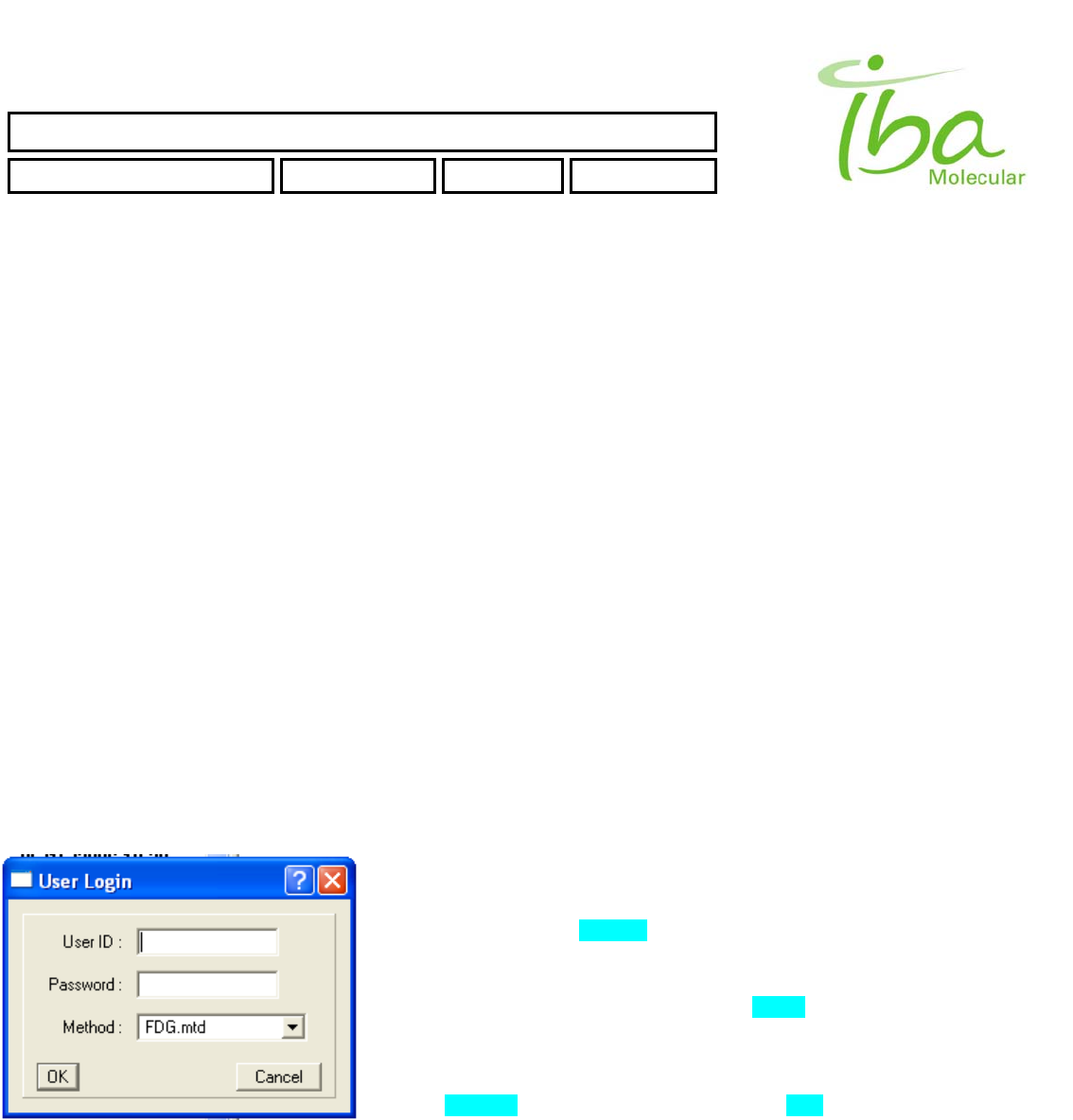
6.11.1 User Login
When application starts User Login Dialog will appear. Note that Windows
OS login and MPB application login are not the same. User must enter
correct User ID and Password. Only authorized users can run MPB
application. See section 6.11.3.4.for Instructions on how to create additional
Users
Choose appropriate method from Method Combo Box (list of methods is
loaded from \METHODS folder). See section 6.12.2. for information on how
to create new Method.
Click OK button to continue. Application will check User ID, Password and
Load Method according to *.mtd file. If no errors occur main screen will
appear (Figure 7). (In case of error - see section 6.13)
IBA Molecular | Apr 06 Direction: MANXXXX © IBA/All Rights Reserved
SYNTHERA ™ USER MANUAL
FDG000130 11/17/2006 Rev.: 1 Pg. 27 of 60
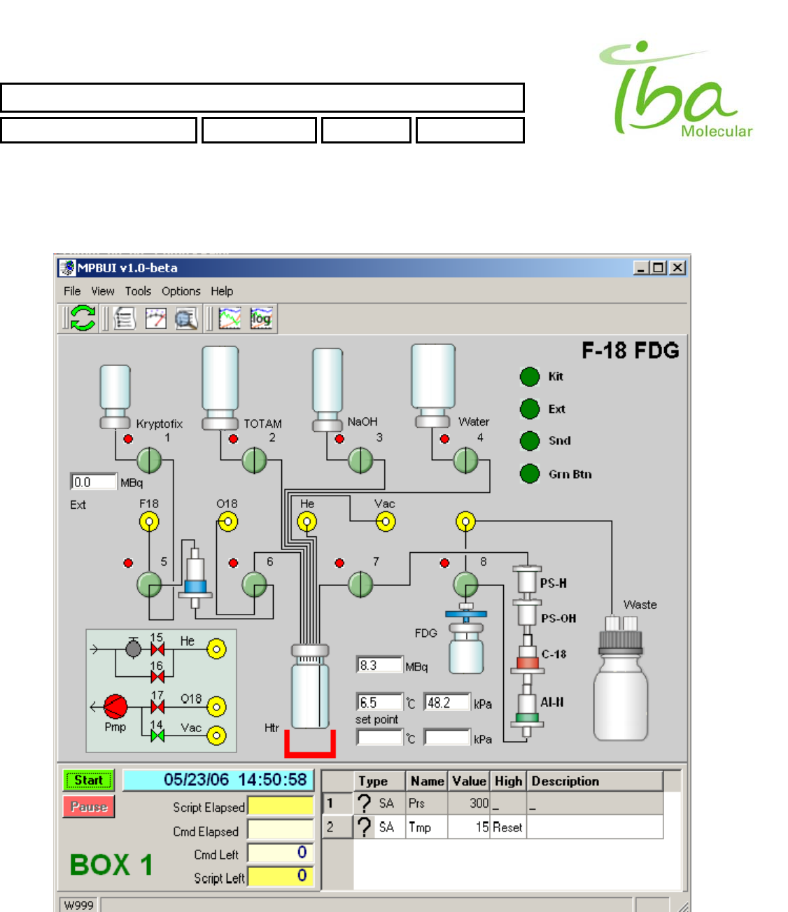
6.11.2 Main Screen
Figure 7
IBA Molecular | Apr 06 Direction: MANXXXX © IBA/All Rights Reserved
SYNTHERA ™ USER MANUAL
FDG000130 11/17/2006 Rev.: 1 Pg. 28 of 60
6.11.3 Menu items
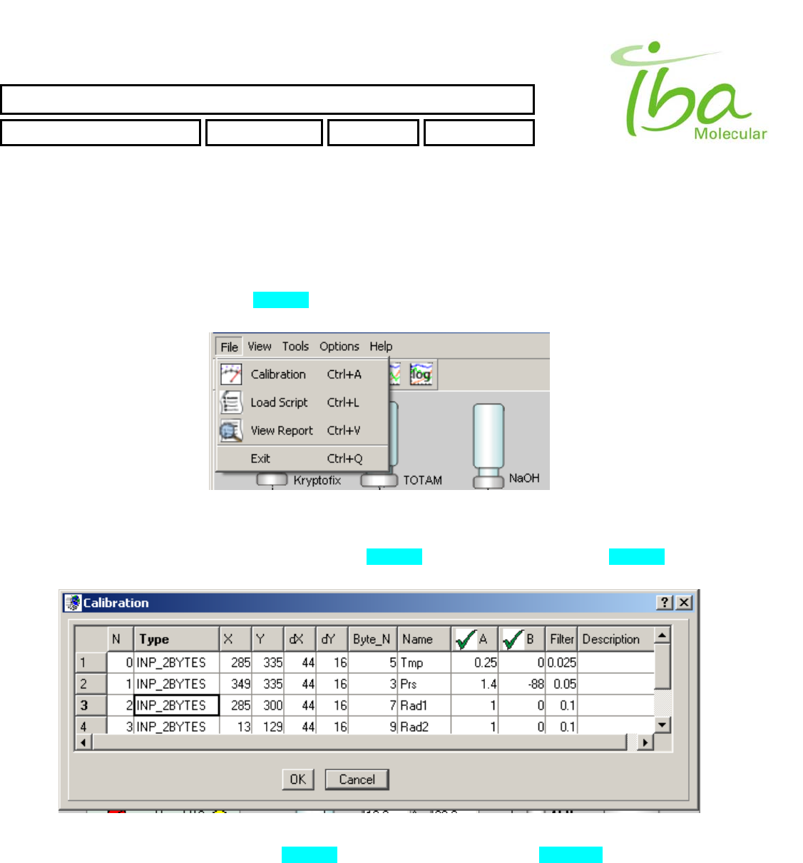
6.11.3.1 File
This menu selection is used to change Calibration parameters, to Load Script files, to view existing Report files and allows
exit an application. All these selections also exist in File Tool Bar.
To load Script selects “File-Load Script” (Figure 8). File selection dialog appears. Script files are assigned extension
“*.csv” and placed in application folder C:\MPB\SCRIPTS. An attempt to load script from another folder will result an error.
Figure 8
To change calibration parameters select “File-Calibration” (Figure 8). Calibration dialog appears (Figure 9). One can
change calibration parameters of INP_2BYTES Indicators and OUT_2BYTES Signals for loaded Signal Definition file.
Figure 9
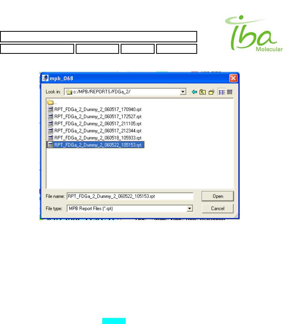
To view Report file select “File-View Report” (Figure 8). File selection dialog appears (Figure 10).
IBA Molecular | Apr 06 Direction: MANXXXX © IBA/All Rights Reserved
SYNTHERA ™ USER MANUAL
FDG000130 11/17/2006 Rev.: 1 Pg. 29 of 60
IBA Molecular | Apr 06 Direction: MANXXXX © IBA/All Rights Reserved
Figure 10
Report files are assigned extension “*.rpt” and placed in application folder C:\MPB\REPORTS\method_file_name\. An
attempt to view Report from another folders will result an error. Reports may not be deleted or modified by the user. The
Report file name will be RPT_methodFileName_scriptFileName_date_time.rpt for example:
RPT_FDGa_2_Dummy_2_060522_105153.rpt
It means:
FDG_2 - method file name
Dummy_2 - script file name
060522 - date when script was started - 22 May 2006
105153 - time when script was started (military format) - 10:51:53
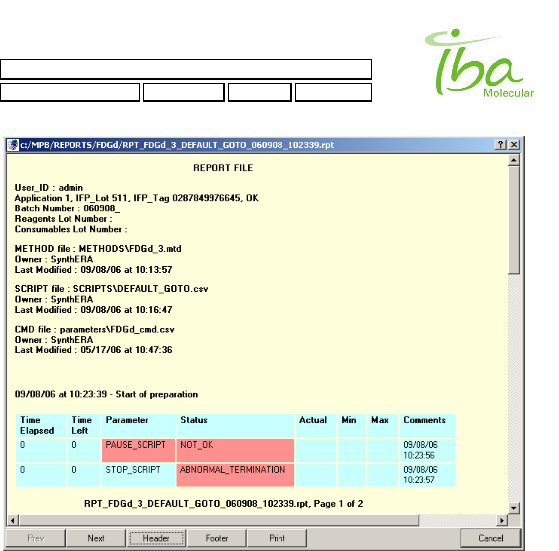
Example of View Report window is shown in Figure 11
SYNTHERA ™ USER MANUAL
FDG000130 11/17/2006 Rev.: 1 Pg. 30 of 60
IBA Molecular | Apr 06 Direction: MANXXXX © IBA/All Rights Reserved
Figure 11
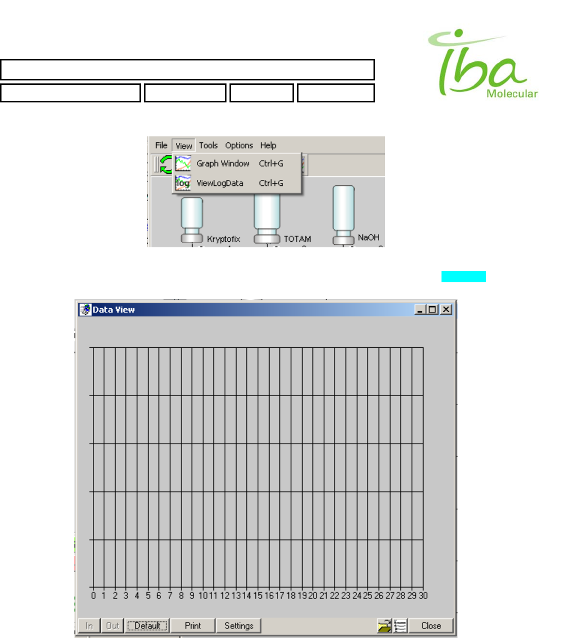
6.11.3.2 Graphical Log Viewer
This menu selection is used to open Graph window and start LogData Viewer. All these selections are also exists in File
Tool Bar.
SYNTHERA ™ USER MANUAL
FDG000130 11/17/2006 Rev.: 1 Pg. 31 of 60
IBA Molecular | Apr 06 Direction: MANXXXX © IBA/All Rights Reserved
Figure 12
To view existing LogData file select “View-ViewLogData” (Figure 12). DataView Window will appear (Figure 13).
LOG_DATA files are assigned extension “*.csv” and placed in application folder C:\MPB\LOGS\.
Figure 13
SYNTHERA ™ USER MANUAL
FDG000130 11/17/2006 Rev.: 1 Pg. 32 of 60
To view LOG_DATA first load method by pressing Open Method button on bottom of the main screen. After that you
can load LOG_DATA by pressing Load Data button.
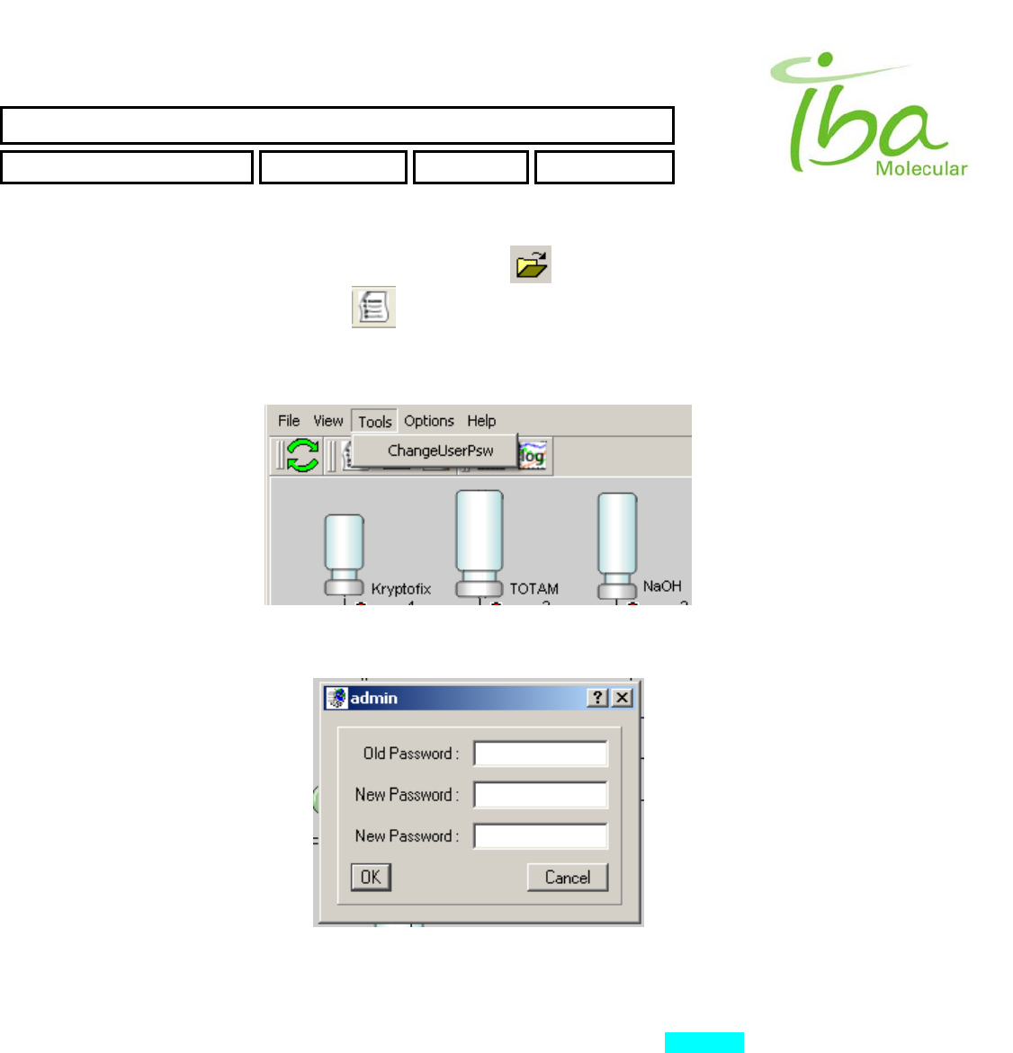
6.11.3.3 Tools
This selection is used to change current user password.
Figure 14
Figure 15
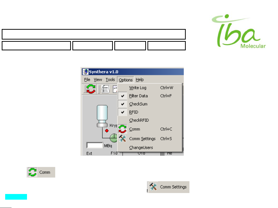
6.11.3.4 Options
This menu selection is used to configure and adjust parameters of MPB application (Figure 16). Those selections
accessible only for users with Admin permissions (local MPB application permission - don't mix-up with Windows user
permissions)
There are three flags (switches), which could be ON or OFF.
Write Log - when it's ON - data is continuously writing to LOG_DATA file.
Filter Data - when it's ON - Filter is applied for all Incoming analog data. OFF - raw data, no filtering
CheckSum - when it's ON - checkSum is used to verify communication information with Synthera BOX. DON'T change
this setting - will result in a communication error.
IBA Molecular | Apr 06 Direction: MANXXXX © IBA/All Rights Reserved
SYNTHERA ™ USER MANUAL
FDG000130 11/17/2006 Rev.: 1 Pg. 33 of 60
IBA Molecular | Apr 06 Direction: MANXXXX © IBA/All Rights Reserved
Figure 16
By pressing you can START or STOP communication between MPB application and Synthera BOX.
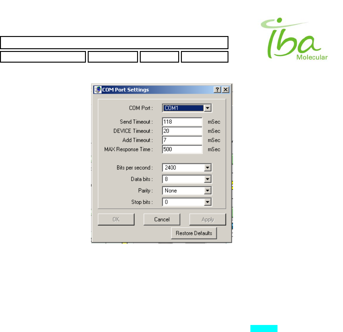
To access communication settings select “Options-Comm Settings” . Dialog window opens as shown
in Figure 17.
Note: to access Communication Settings dialog, make sure that you start communication first.
SYNTHERA ™ USER MANUAL
FDG000130 11/17/2006 Rev.: 1 Pg. 34 of 60
IBA Molecular | Apr 06 Direction: MANXXXX © IBA/All Rights Reserved
Figure 17
When changing COM port number remember to also change COM port setting in the communication settings file
referenced in the method file. When multiple methods are installed on the same computer using different COM ports, the
port number from method file is used and COM port selection in tools menu is ignored.
Other parameters listed in this window allow fine-tuning of communication settings to accommodate specific installation
environment and are adjusted at installation. They are generally not to be changed by the user unless directed by support
personnel. To change parameters when directed by support personnel enter modified number and press ENTER
followed by clicking OK.
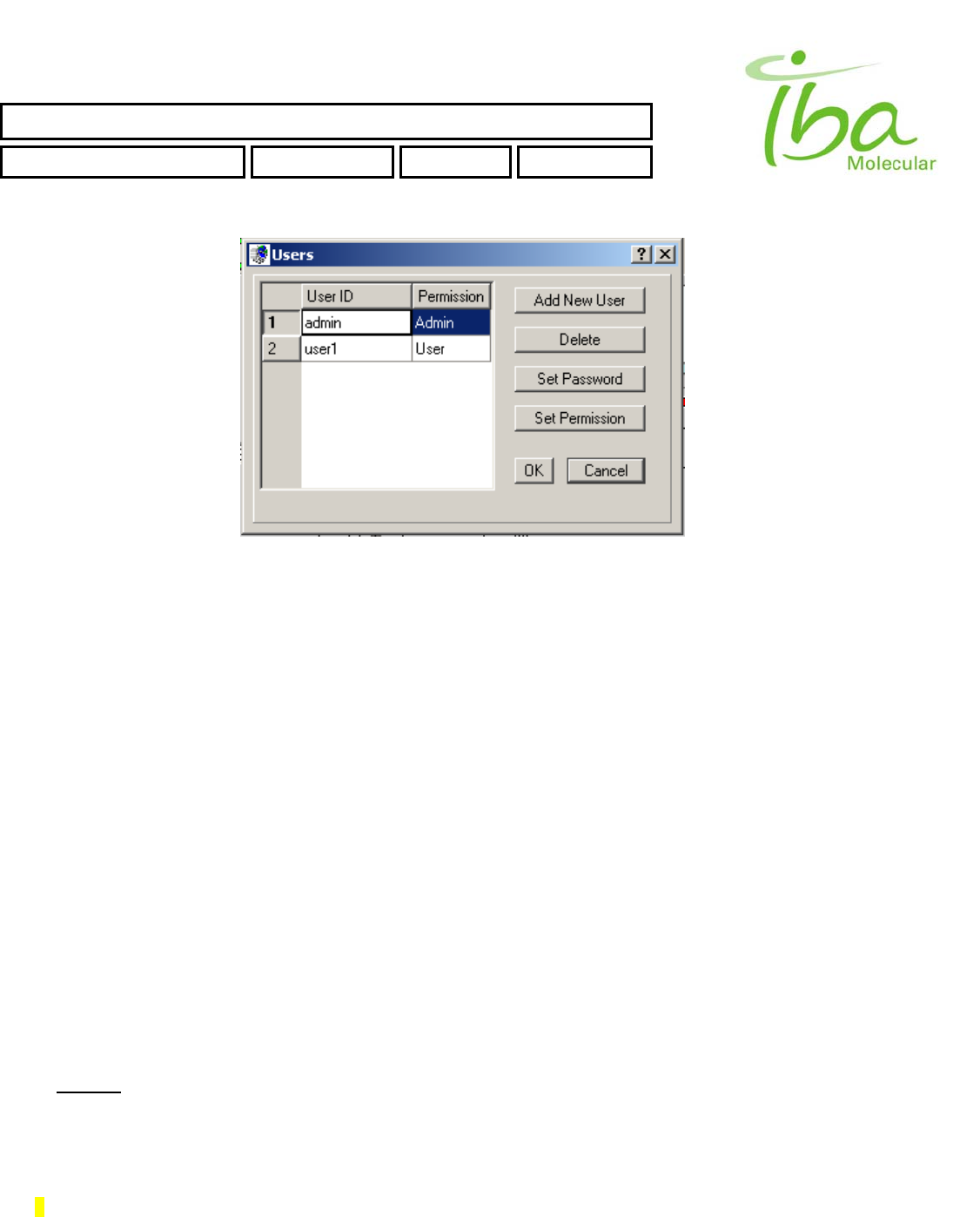
To change Users settings select “Options - ChangeUsers”. Dialog window opens as shown in Figure 18.
SYNTHERA ™ USER MANUAL
FDG000130 11/17/2006 Rev.: 1 Pg. 35 of 60
IBA Molecular | Apr 06 Direction: MANXXXX © IBA/All Rights Reserved
Figure 18
By this dialog you can create new user, delete existing users, set user's password and permissions. These settings are
applicable only for Internal MPB application.
6.12 Create new Methods, Scripts, Parameters
Users are not allowed to modify directly any of existing Methods, Scripts, Bitmaps and Parameters files in folders:
C:\MPB\METHODS\
C:\MPB\PARAMETERS\
C:\MPB\BITMAPS\
C:\MPB\SCRIPTS\
Instead user has to create a new instance of those files with any desirable modifications.
To create new methods, scripts or parameters files you MUST login (Windows login) as a member of MPB_PowerUser
group.
6.12.1 Create New Communication Settings
To create new communication settings file follow the next steps:
• Copy existing comm_set file from C:\MPB\PARAMETERS folder to any temporary folder (for example C:\TEMP)
• Open file in temporary folder (C:\TEMP) with NOTEPAD.EXE
• Make changes
• Save As file with a new name
• Copy new file from temporary folder (C:\TEMP) to C:\MPB\PARAMETERS
You must define COM port number according to your system configuration.
Example of communications file is provided below:
COM1,

SYNTHERA ™ USER MANUAL
FDG000130 11/17/2006 Rev.: 1 Pg. 36 of 60
6.12.2 Create New Method
To create new Method file follow the next steps:
• Copy existing Method file from C:\MPB\METHODS folder to any temporary folder (for example C:\TEMP)
• Open file in temporary folder (C:\TEMP) with NOTEPAD.EXE
• Make changes
• Save As file with a new name
• Copy new file from temporary folder (C:\TEMP) to C:\MPB\METHODS
6.12.3 Create New Script
To create new Script file follow the next steps:
• Copy existing Script file from C:\MPB\SCRIPTS folder to any temporary folder (for example C:\TEMP)
• Open file in temporary folder (C:\TEMP) with NOTEPAD.EXE
• Make changes
• Save As file with a new name
• Copy new file from temporary folder (C:\TEMP) to C:\MPB\SCRIPTS
6.12.4 Create New Signal Definition file
To create new Signal Definition file follow the next steps:
• Copy existing Signal Definition file from C:\MPB\PARAMETERS folder to any temporary folder (for example
C:\TEMP)
• Open file in temporary folder (C:\TEMP) with NOTEPAD.EXE
• Make changes
• Save As file with a new name
• Copy new file from temporary folder (C:\TEMP) to C:\MPB\PARAMETERS
6.12.5 Create New Graph settings
To create new Graph Settings file follow the next steps:
• Copy existing Graph Settings file from C:\MPB\PARAMETERS folder to any temporary folder (for example
C:\TEMP)
• Open file in temporary folder (C:\TEMP) with NOTEPAD.EXE
• Make changes
• Save As file with a new name
IBA Molecular | Apr 06 Direction: MANXXXX © IBA/All Rights Reserved
SYNTHERA ™ USER MANUAL
FDG000130 11/17/2006 Rev.: 1 Pg. 37 of 60
• Copy new file from temporary folder (C:\TEMP) to C:\MPB\PARAMETERS
6.12.6 Create New Bitmap
To create new Graph Settings file follow the next steps:
• Crete file in temporary folder (for example C:\TEMP) with PAINT.EXE
• Copy new file from temporary folder (C:\TEMP) to C:\MPB\BITMAPS
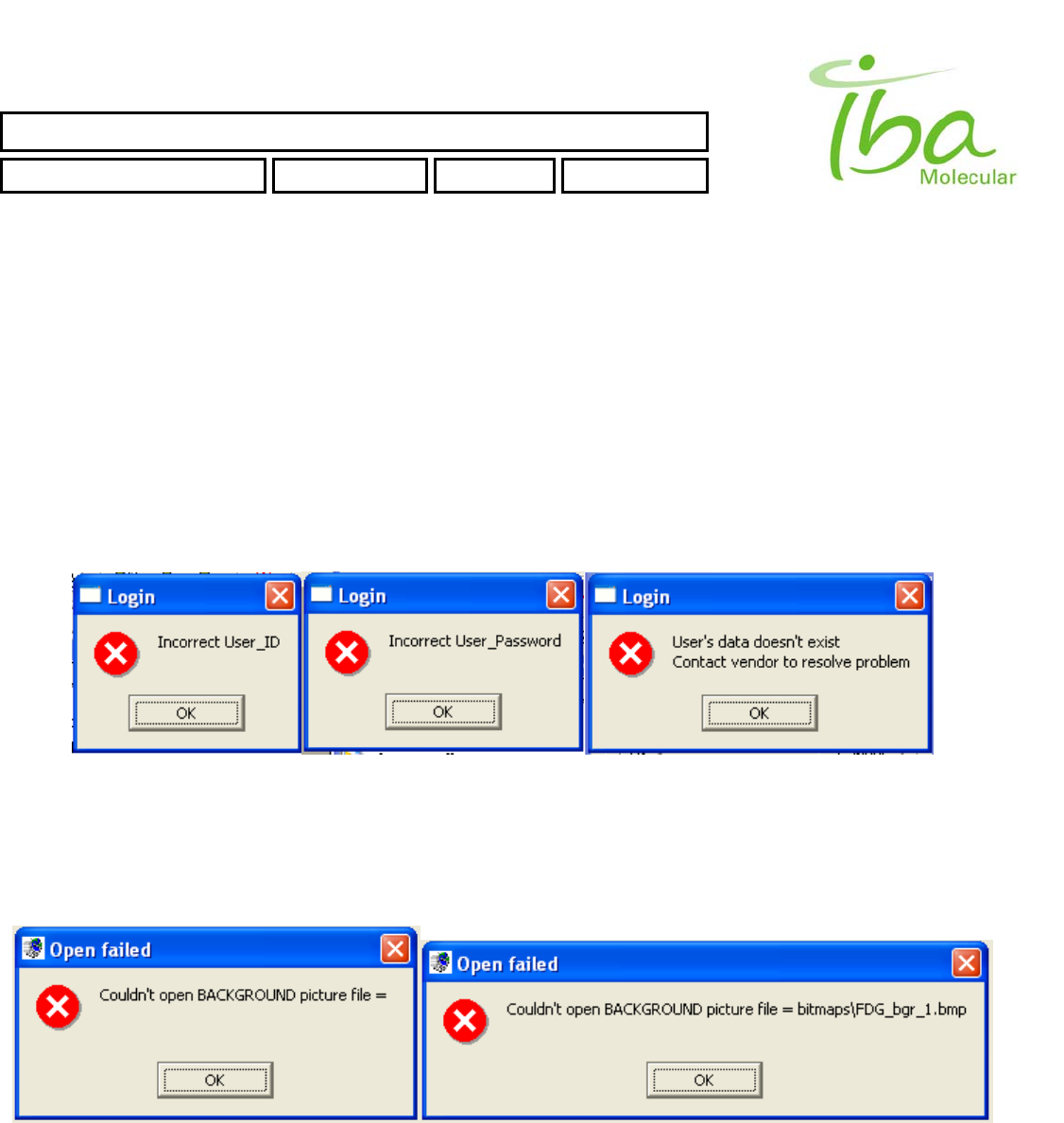
6.13 Errors and trouble-shootings
6.13.1 User Login
List of possible errors during User Login operation
User has to reenter correct User ID or User Password to login. If user data has been corrupted or deleted, contact
Customer Support.
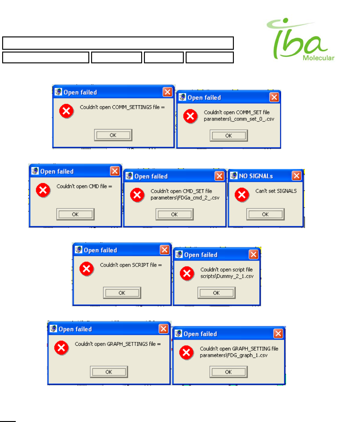
6.13.2 Method file errors
The following error messages may appear when starting application. Their explanation and possible causes are provided
below:
Check If first line (background bitmap) in Method file is empty or contains a name of a file that does not exist.
IBA Molecular | Apr 06 Direction: MANXXXX © IBA/All Rights Reserved
SYNTHERA ™ USER MANUAL
FDG000130 11/17/2006 Rev.: 1 Pg. 38 of 60
IBA Molecular | Apr 06 Direction: MANXXXX © IBA/All Rights Reserved
Second line (communication settings) in Method file is empty or refers to a nonexistent COMM_SET file
Third line (Signals Definition file) in Method file is empty or points to an incorrect CMD file
Fourth line (Script) in Method file is empty or is pointing to an incorrect SCRIPT file
Fifth line (Graph settings) in Method file is empty or is pointing to a wrong GRAPH_SET file
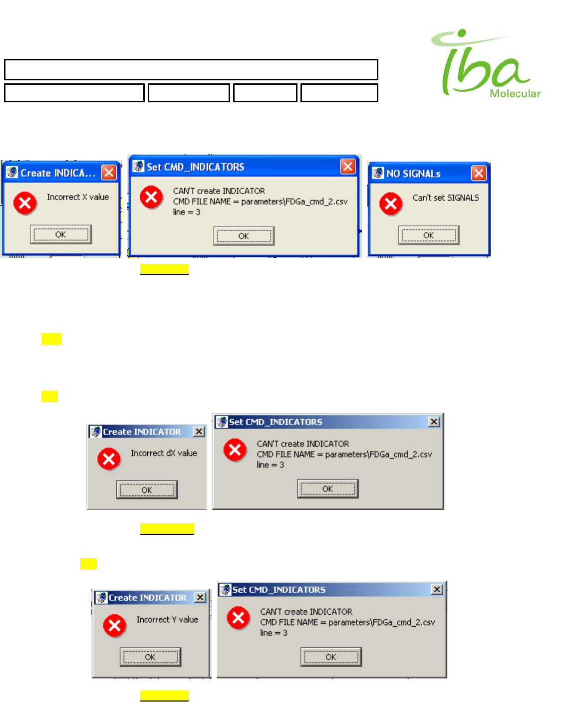
6.13.3 Errors in Signal Definition file
Note: line number in Error Messages counts from 0 (0, 1, 2, …).
SYNTHERA ™ USER MANUAL
FDG000130 11/17/2006 Rev.: 1 Pg. 39 of 60
6.13.3.1 INP_BIT errors
>>Too small or too big value of X position. It must be in range (0 < X < 600)
Example of line in Signal Definition file will generate this error
INP_2BYTES,285,335,44,16,5,Tmp,1.,0.,0.1,
INP_2BYTES,285,293,44,16,3,Prs,1.,0.,0.1,
INP_2BYTES,285,314,44,16,7,Rad,1.,0.,0.1,
INP_BIT,-073,103,29,15,bitmaps\Vl1.bmp,bitmaps\Vl2.bmp,0,0,iV1a,
or
INP_2BYTES,285,335,44,16,5,Tmp,1.,0.,0.1,
INP_2BYTES,285,293,44,16,3,Prs,1.,0.,0.1,
INP_2BYTES,285,314,44,16,7,Rad,1.,0.,0.1,
INP_BIT,673,103,29,15,bitmaps\Vl1.bmp,bitmaps\Vl2.bmp,0,0,iV1a,
,
>>Too small or too big value of dX position. It must be in range (0 < X + dX < 600)
Example of line in Signal Definition file will generate this error
INP_BIT,073,103,629,15,bitmaps\Vl1.bmp,bitmaps\Vl2.bmp,0,0,iV1a,
>>Too small or too big value of Y position. It must be in range ( 0 < Y < 400 )
IBA Molecular | Apr 06 Direction: MANXXXX © IBA/All Rights Reserved
SYNTHERA ™ USER MANUAL
FDG000130 11/17/2006 Rev.: 1 Pg. 40 of 60
Example of line in Signal Definition file will generate this error
INP_BIT,073,603,29,15,bitmaps\Vl1.bmp,bitmaps\Vl2.bmp,0,0,iV1a,
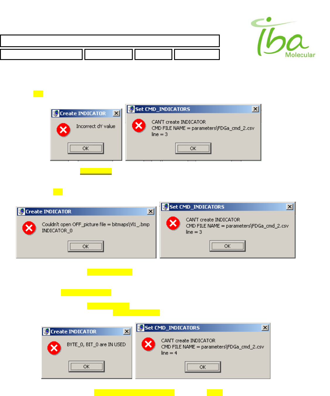
>>Too small or too big value of dY position. It must be in range ( 0 < Y + dY < 400 )
Example of line in Signal Definition file will generate this error
INP_BIT,073,103,29,615,bitmaps\Vl1.bmp,bitmaps\Vl2.bmp,0,0,iV1a,
>>Incorrect file name for Indicator OFF state picture
Example of line in Signal Definition file will generate this error
INP_BIT,073,103,29,15,bitmaps\Vl1_.bmp,bitmaps\Vl2.bmp,0,0,iV1a,
>>Incorrect file name for Indicator ON state picture will generate similar Error Messages
INP_BIT,073,103,29,15,bitmaps\Vl1_.bmp,bitmaps\Vl2.bmp,0,0,iV1a,
>>Attempt to assign for Indicator the BYTE number and BIT number are already in use by some other Indicator.
Example of lines in Signal Definition file will generate this error
IBA Molecular | Apr 06 Direction: MANXXXX © IBA/All Rights Reserved
SYNTHERA ™ USER MANUAL
FDG000130 11/17/2006 Rev.: 1 Pg. 41 of 60
INP_2BYTES,285,335,44,16,5,Tmp,1.,0.,0.1,
INP_2BYTES,285,293,44,16,3,Prs,1.,0.,0.1,
INP_2BYTES,285,314,44,16,7,Rad,1.,0.,0.1,
INP_BIT,073,103,29,15,bitmaps\Vl1.bmp,bitmaps\Vl2.bmp,0,0,iV1a,
INP_BIT,073,117,29,15,bitmaps\Vl3.bmp,bitmaps\Vl4.bmp,0,0,iV1b,
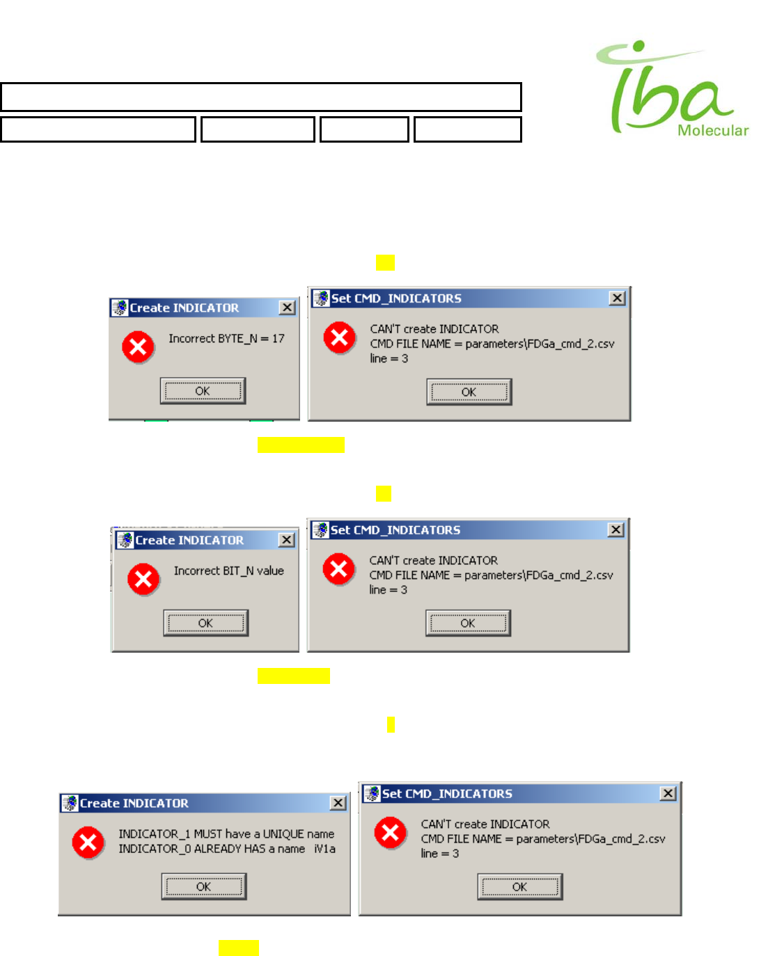
>>Attempt to assign for Indicator incorrect BYTE number. Should be in range (0 < BYTE_N < MAX_BYTE_N)
Example of line in Signal Definition file will generate this error
INP_BIT,073,103,29,15,bitmaps\Vl1.bmp,bitmaps\Vl2.bmp,17,0,iV1a,
>>Attempt to assign for Indicator incorrect BIT number. Should be in range (0 < BIT_N < 7)
Example of line in Signal Definition file will generate this error
INP_BIT,073,103,29,15,bitmaps\Vl1.bmp,bitmaps\Vl2.bmp,0,9,iV1a,
>>Attempt to duplicate the Indicator NAME.
Example of lines in Signal Definition file will generate this error
IBA Molecular | Apr 06 Direction: MANXXXX © IBA/All Rights Reserved
SYNTHERA ™ USER MANUAL
FDG000130 11/17/2006 Rev.: 1 Pg. 42 of 60
INP_2BYTES,285,335,44,16,5,Tmp,1.,0.,0.1,
INP_2BYTES,285,293,44,16,3,Prs,1.,0.,0.1,
INP_2BYTES,285,314,44,16,7,Rad,1.,0.,0.1,
INP_BIT,073,103,29,15,bitmaps\Vl1.bmp,bitmaps\Vl2.bmp,0,0,iV1a,
INP_BIT,073,117,29,15,bitmaps\Vl3.bmp,bitmaps\Vl4.bmp,0,0,iV1a,
6.13.3.2 OUT_BIT errors
Error messages generated by incorrect settings of OUT_BIT Signal are the same as for INP_BIT Indicator.
>>Too small or too big value of X position. It must be in range ( 0 < X < 600 )
>>Too small or too big value of dX position. It must be in range ( 0 < X + dX < 600 )
>>Too small or too big value of Y position. It must be in range ( 0 < Y < 400 )
>>Too small or too big value of dY position. It must be in range ( 0 < Y + dY < 400 )
>>Incorrect file name for Signal OFF state picture
>>Incorrect file name for Signal ON state picture.
>>Attempt to assign for Signal incorrect BYTE number. Should be in range (0 < BYTE_N < N_send_bytes)
>>Attempt to assign for Signal incorrect BIT number. Should be in range (0 < BIT_N < 7)
>>Attempt to assign for Signal the BYTE number and BIT number are already in use by some other Signals.
>>Attempt to duplicate the Indicator NAME.
6.13.3.3 OUT_2BYTES errors
Error messages generated by incorrect settings of OUT_2BYTES Signal are the same as for INP_BIT Indicator with two
exceptions:
• No Error BIT number
• Two addition Errors related with Calibration parameters setting
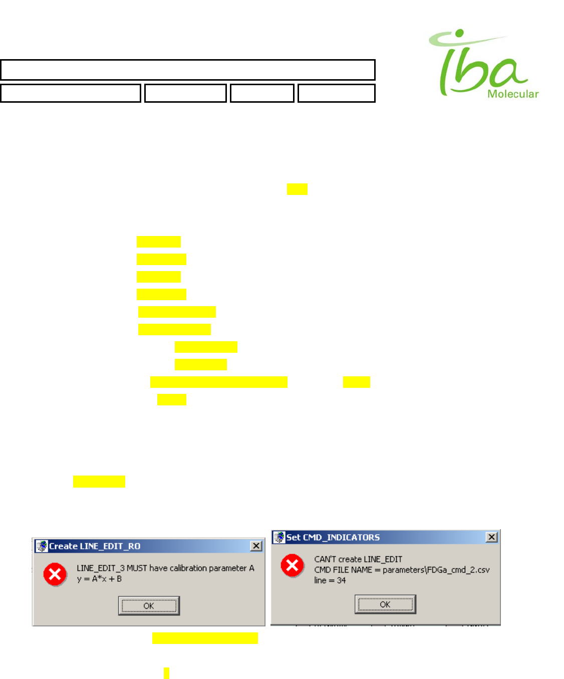
>>Attempt to create Signal without Calibration parameter A
Example of line in Signal Definition file will generate this error
OUT_2BYTES,285,368,44,16,5,Tmp,,,,
IBA Molecular | Apr 06 Direction: MANXXXX © IBA/All Rights Reserved
SYNTHERA ™ USER MANUAL
FDG000130 11/17/2006 Rev.: 1 Pg. 43 of 60
IBA Molecular | Apr 06 Direction: MANXXXX © IBA/All Rights Reserved
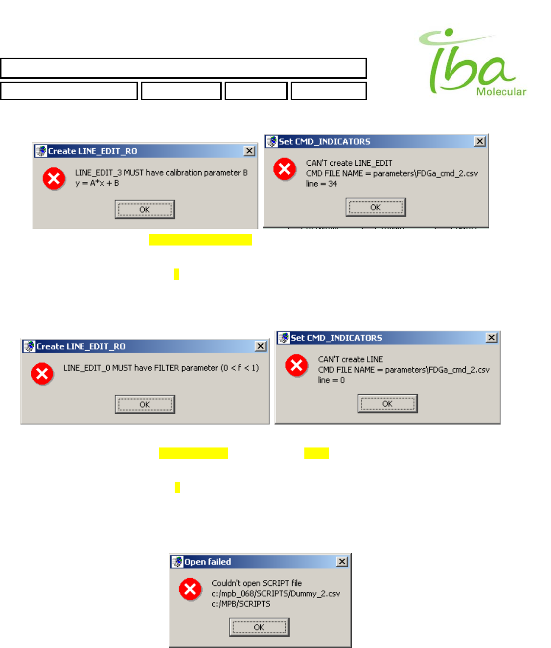
>>Attempt to create Signal without Calibration parameter B
Example of line in Signal Definition file will generate this error
OUT_2BYTES,285,368,44,16,5,Tmp,1.0,,,
6.13.3.4 INP_2BYTES errors
Error messages generated by incorrect settings of INP_2BYTES Indicator are the same as for OUT_2BYTES Signal with
one additional Error
>>Attempt to create Indicator without Filter parameter Analog Indicator 6.7.2
Example of line in Signal Definition file will generate this error
INP_2BYTES,285,335,44,16,5,Tmp,1.,0.,,
6.13.4 Script Errors
All Scripts could be loaded ONLY from folder C:\MPB\SCRIPTS\. An attempt to load script from another folder will result
an error:
All Script commands lines are validated during Load Script procedure. There are several typical errors could occur during
script validation. In case of an error MPB application will generate an error message and highlight the cell in script table
with incorrect value. You can see list of typical errors below:
SYNTHERA ™ USER MANUAL
FDG000130 11/17/2006 Rev.: 1 Pg. 44 of 60
IBA Molecular | Apr 06 Direction: MANXXXX © IBA/All Rights Reserved
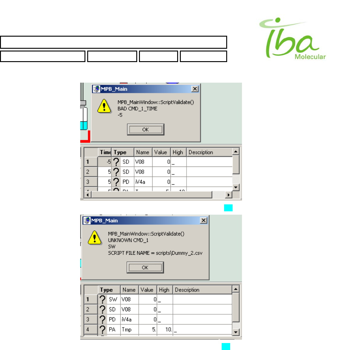
>>Time value in script CMD set to incorrect value. For more Information see section 6.8
>>CMD_TYPE set to incorrect value. For list of valid Script Commands see section 6.8
SYNTHERA ™ USER MANUAL
FDG000130 11/17/2006 Rev.: 1 Pg. 45 of 60
IBA Molecular | Apr 06 Direction: MANXXXX © IBA/All Rights Reserved
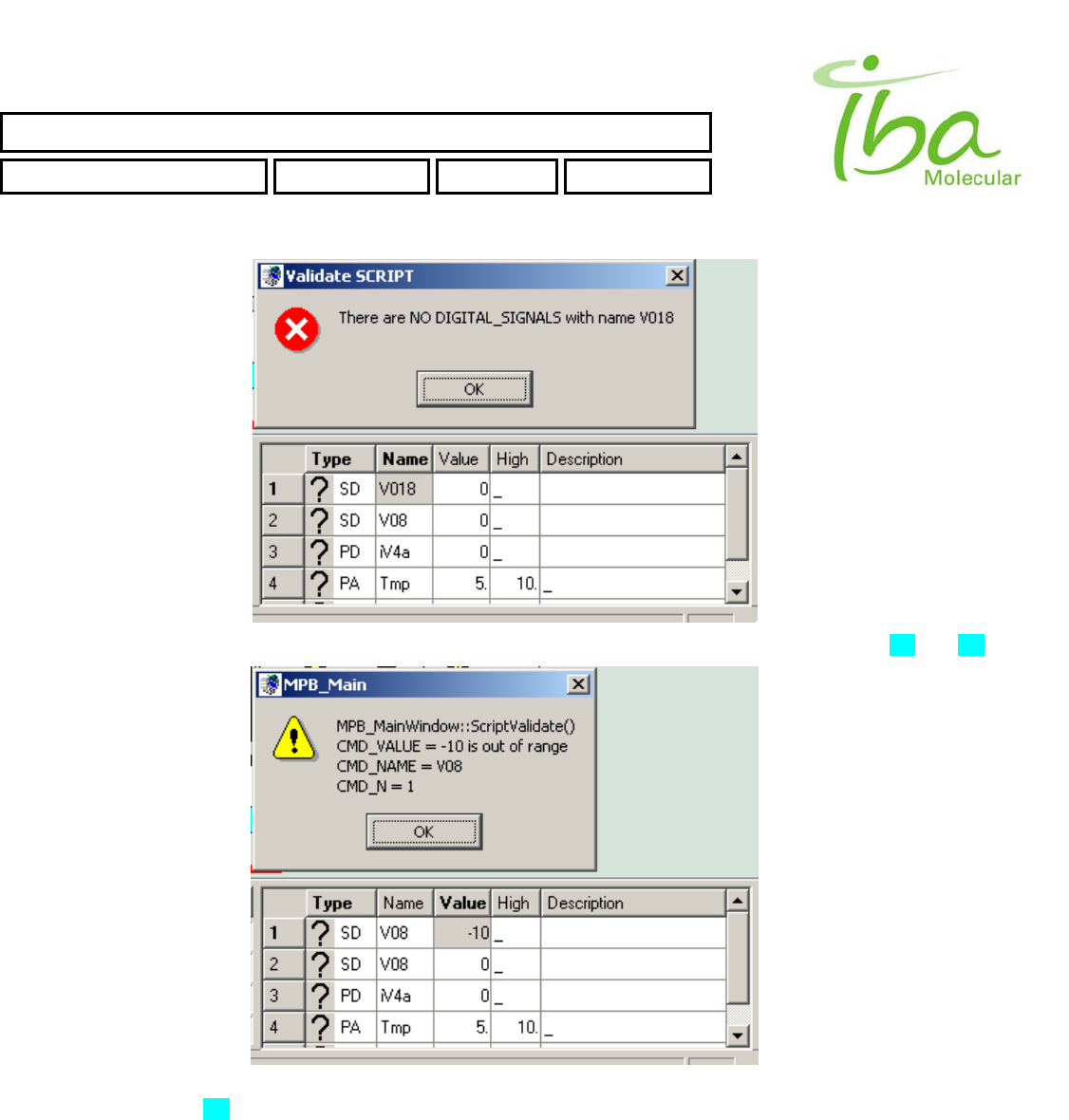
>>Name of Signal or Indicator Is not from the Signal Definition Table list. For more information see section 6.8 and 6.7
>>Value of script CMD is incorrect or has inappropriate type (for example double Instead of int). For list of valid Script
CMD values see section 6.8
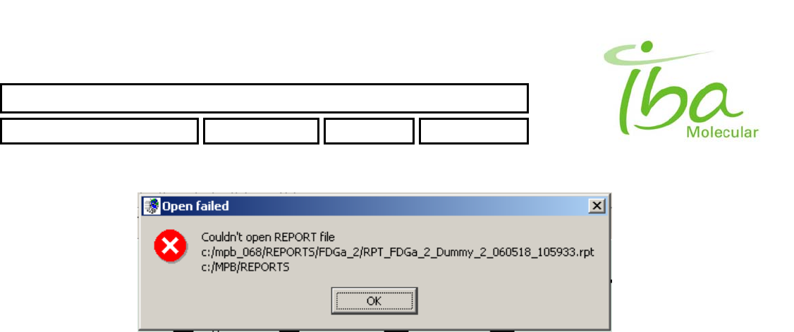
6.13.5 View Report file
Report files are NOT accessible directly for MPB users (except members of MPB_Admin Local group), you can see
those files only via MPB application. All Report files could be open ONLY from folder C:\MPB\REPORTS\. An attempt to
open Report from another folder will result an error:
SYNTHERA ™ USER MANUAL
FDG000130 11/17/2006 Rev.: 1 Pg. 46 of 60
IBA Molecular | Apr 06 Direction: MANXXXX © IBA/All Rights Reserved

SYNTHERA ™ USER MANUAL
FDG000130 11/17/2006 Rev.: 1 Pg. 47 of 60
7 User maintenance
Synthera® is designed for minimal maintenance. No user serviceable parts are located under the covers.
The following Inspection and maintenance steps will insure reliable operation if performed monthly or every 100
production runs whichever comes first:
Inspect compressed air and inert gas connecting tubes and fittings for leakage or damage
Inspect heater including heater cavity for visible contamination. Remove any deposits from the heater cavity
Check that heater moves up and down smoothly and reaches the bottom of the reactor vial when in upper position.
Wipe IFP™ holder grips and cylinder rods with dry clean cloth. Lubricate with pharmaceutical grade petroleum jelly
(petrolatum).
Exterior surfaces of the processing unit and control box must be clean and free from corrosion and visible dents and
damage.
7.1 Cleaning and decontamination
In normal operation some components of Synthera ® processing unit may be exposed to radioactive liquid. Normal
cleaning procedure includes rinsing of passages with solvents compatible with an application and may vary from one
method to another. Normally, only water should be used to rinse Incoming target water lines when Synthera® is used to
process F-18. However all plumbing Inside of the processing module is compatible with wide range of solvents, Including
but not limited to Acetone, Ethanol, Acetonitrile, DMSO etc.
Exterior surfaces of Synthera® processing module are made of corrosion resistant materials, such as stainless steel and
epoxy-coated steel. They can be washed using common methods by spraying and wiping using water based detergents
and alcohol spray for disinfection.
IFP™ is a disposable part and is not intended to be washed or cleaned. Dispose after use in appropriate shielded
storage container.
IBA Molecular | Apr 06 Direction: MANXXXX © IBA/All Rights Reserved

SYNTHERA ™ USER MANUAL
FDG000130 11/17/2006 Rev.: 1 Pg. 48 of 60
8 Applications
8.1 F-18 FDG
8.1.1 Disclaimer
The purpose of this section is to provide general information about process and operation of Synthera ® system for the
purpose of production of F-18 FDG USP (hereinafter referred to as FDG). Intended use of the product and its suitability
for intended use is to be established and validated by the User. Regulatory compliance of the process and product is a
sole responsibility of the User. Detailed description of all operations used for manufacturing, quality control and
dispensing of the product, if required for regulatory compliance, must be documented in User’s Standard Operating
Procedures (SOP).
Development, validation and maintenance of these procedures are a responsibility of the User. All information and
recommendations provided in this manual are for reference only. This information is provided to aid User in development
of SOP’s and appropriate regulatory compliance documentation and is not intended as replacement of such
documentation.
8.1.2 FDG Product Specifications
Reaction Nucleophilic substitution (Hamacher et al.)
Yield (EOS) 60% (70% corrected yield)
Synthesis time < 25 minutes
Preparation time Is the IFP™ reloading time
Radiochemical purity > 98%
Chemical purity USP & EU Pharmacopea compliant
Endotoxins USP & EU Pharmacopea compliant
8.1.3 Materials and supplies
All supplies needed for FDG synthesis are included in three IFP™s:
• IFP™
• Reagents
• Ancillary Supplies
One of each is required for FDG synthesis. Composition and specifications of all three IFP™s is described in this section.
8.1.3.1 Integrated Fluid Processor
Disposable IFP™ (integrated fluidic processor) comprised of 8 rotary valves, 6 vial holders and 2 cartridge holders,
assembled with reactor vial. IFP™ is supplied in individual packaging Is sterilized. Open only in controlled environment
and use aseptic procedures.
IFP™ is intended for single use only. An attempt to re-use IFP™ or misuse it for anther application is not supported by
IBA warranty and not covered by IBA specifications.
IBA Molecular | Apr 06 Direction: MANXXXX © IBA/All Rights Reserved

SYNTHERA ™ USER MANUAL
FDG000130 11/17/2006 Rev.: 1 Pg. 49 of 60
8.1.3.2 Reagents kit
To achieve best results with Synthera ® system use only IBA supplied reagent kits. Use of unapproved reagents may
result in variable results and IBA is not responsible for compliance of the system to specifications whenever OEM or
homemade reagents are used. Use of non-standard reagents may also cause damage to AM components and will void
warranty.
Reagents kit is comprised of 4 reagent vials with Teflon™ faced silicone rubber septa and sealed with aluminum crimp
seals. Vials are packaged in a protective box and labeled individually.
Each lot of reagents is supplied complete with Certificate of Analysis. MSDS and complete analytical data including
spectra and chromatograms are available upon request.
Individual vials contents are as follows:
8.1.3.2.1 Vial #1 Cryptand solution
Preparation: The Cryptand solution for one synthesis is a mixture of:
22.6 mg ± 0.1 mg of Cryptand 222
4.2 mg ± 0.1mg of K2C03
300 ul ±10ul Acetonitrile
300 ul ±10ul Water for Injection USP
Cryptand 222 (constituent 1) is dissolved in the acetonitrile (constituent 4), and K2C03 (constituent 2) in the Water for
Injections (constituent 3). Then both solutions are mixed together. 600 ul ± 0.01 ml of the solution are transferred into the
2 ml serum vial, closed with 11 mm teflon faced silicone stopper, capped and crimped.
Sterility sterile
Bacterial endotoxin <2.0 EU/mI
Constituent 1 Cryptand 222
Purity (OC) >99%
Identity (IR-spectrum) conforms
Melting range 68 - 72°C
Constituent 2 Potassium carbonate
Assay (acidimetric; dried substance) 99.5 - 100.5 %
Alkalinity strongly alkaline reaction
Reaction of carbonates passes test
Reaction of potassium passes test
Appearance of solution passes test
Insoluble substances passes test
Chloride (Cl) <0.002 %
Calcium (Ca) <0.005%
Sulfate (SOs) <0.01 %
Fe (Iron) <0.001 %
Loss on drying <0.5%
Constituent 3 Water for Injectable solutions
Degree of coloration of solution Not more intensely colored than ref sol. B9
Clarity and degree of opalescence <2.5 FTU
Conductivity, container> 10 ml <5uS/cm
Acidity or alkalinity Corresponds to test for alkalinity or acidity
Oxidizable substances the solution remains faintly pink,
Chloride, containers> 100 ml No change in appearance for at least 15 min.
IBA Molecular | Apr 06 Direction: MANXXXX © IBA/All Rights Reserved

SYNTHERA ™ USER MANUAL
FDG000130 11/17/2006 Rev.: 1 Pg. 50 of 60
Nitrate <0.2 ppm
Sulfate No change in appearance for at least 1 hour
Ammonium < 0.2 ppm
Calcium and Magnesium Blue color
Heavy metals <0.1ppm
Residue on evaporation per 100 ml <3mg
Particulate matter> 10 micrometers/mI <25
Particulate matter > 25 micrometers/nil <3
8.1.3.2.2 Vial #2 Mannose triflate in dry acetonitrile
Preparation: The Mannose triflate in dry acetonitrile for one synthesis is a mixture of the following compounds.
Components are supplied in two separate vials and are combined immediately prior to the synthesis:
20.0 mg ± 0.1 mg Mannose triflate
1.50 ml ± 0.01 ml Dry acetonitrile
Mannose triflate (constituent 2) is dissolved in dry acetonitrile (constituent 1). 1.50 ml ± 0.01 ml of the solution are
transferred into 4.5 ml 13 mm crimp top vial, sealed with Teflon™ faced silicone septa, capped and crimped
Parameter Specification
Sterility sterile
Bacterial endotoxin <2.0 EU/ml
Constituent 1 Acetonitrile for DNA synthesis
Parameter Specification
Purity (CC) min 99,8%
Identity (IR) conforms to reference spectrum
Acidity <0.001 meq/g
Alkalinity <0.0002 meg/g
Residue on evaporating <1 mg/l
Water <0.001 %
Constituent 2 Mannose triflate
Parameter Specification
Appearance colorless crystals
Melting point Capillary: 119-122°C
Optical Rotation, Polarimetry α d 20 = -16.0 ± 0.8° (c > 2.0, CHCI3)
Impurities by HPLC – assay 95-105%
sum 1-OH-TAM 2-OH-TAM <0.2%
Each unknown <0.1%
sum of unknown <0.5
Fluorine containing by F19 NMR
Trifluromethane sulfonic acid <0.2%
Each unknown <0.1mol-%
Unknown combined <0.3mol-%
Residual solvents by GC
Cyclohexane <0.25%
Dichloromethane <0.18%
Pyridin <0.01%
ethanol <0.1%
IBA Molecular | Apr 06 Direction: MANXXXX © IBA/All Rights Reserved

SYNTHERA ™ USER MANUAL
FDG000130 11/17/2006 Rev.: 1 Pg. 51 of 60
Loss on drying <0.6%
Elemental analysis C 37.5, H 3.99, O 6.68 +/-0.3%
8.1.3.2.3 Vial 3 Sodium hydroxide
Preparation: The Sodium hydroxide solution for one synthesis is a mixture of the following compounds: 1 N NaOH,
(constituent 1) and 10 %v/v Ethanol (constituent 2)
1 ml ± 0.02 ml of the solution are transferred into 3 ml, 11 mm crimp top vial sealed with teflon faced silicone septa
capped and crimped.
Parameter Specification
Sterility sterile
Bacterial endotoxin < 10.0 EU/mI
Constituent 1 Sodium hydroxide solution, 1 N
Parameter Specification
Amount-of-substance concentration C(NaOH) = 2 mol/I +/- 0.1 %
Titer volumetric solution is checked by means of hydrochloric acid standard solution tested against a NIST
traceable volumetric standard 1.000
Constituent 2 Ethanol
Parameter Specification
Appearance conforms
IR spectroscopy (Identity) conforms to reference spectrum
Density (020/20) 0.,790 - 0.793
Acidity/Alkalinity conforms to Ph. Eur or USP reaction
Volatile impurities Acetal + Acetaldehyde < 10 ppm
Benzene < 2 ppm
Other < 300 ppm
UV-absorption conforms
Residue on evaporation <25 ppm
Assay (GC) >99.5Vol.%
8.1.3.2.4 Vial 4 Sterile Water for injection
Preparation:
10.0 ml ± 0.2 ml of Water for Injection USP is introduced into the 10 ml crimp top “insulin” vial, sealed with teflon faced
silicone rubber stopper an crimped with a 13 mm crimp cap, The vial is autoclaved for 30 min at 121 C.
Parameter Specification
Sterility sterile
Bacterial endotoxin <0.25 lU/mI
Degree of coloration of solution Not more intensely colored than B9
Clarity and degree of opalescence < 2.5 FTU
Conductivity, container> 10 ml < 5 uS/cm
Acidity or alkalinity Corresponds to test for alkalinity or acidity
Oxidizable substances the solution remains faintly pink,
Chloride, containers 100 ml No change in appearance for 15 min.
Nitrate < 0.2 ppm
Sulfate No change in appearance for 1 hour
Ammonium <0,2 ppm
Calcium and Magnesium Blue color
Heavy metals < 0.1 ppm
IBA Molecular | Apr 06 Direction: MANXXXX © IBA/All Rights Reserved

SYNTHERA ™ USER MANUAL
FDG000130 11/17/2006 Rev.: 1 Pg. 52 of 60
Residue on evaporation per 100 ml < 3 mg
Particulate matter 10 micrometers/mI < 25
Particulate matter 25 micrometers/ml < 3
8.1.3.3 Ancillary Supplies
Includes purification components (cartridges and filters), solvents used for their preparation, final product container and
other items used in FDG synthesis. Use of this kit is not mandatory. Equivalent materials from other sources may be
used without loss of performance or product quality, provided that all specifications listed below are met.
One IFP™ is sufficient for 50 FDG productions.
IFP™ includes:
# Item description Qty
1 Alumina B Sep-Pak Plus Cartridge 50
2 C18 Sep-Pak Plus Cartridge 50
3 QMA Sep-Pak Cartridge 50
4 SCX Maxi-Clean cartridge 50
5 Membrane Sterilizing Filter, 25 mm, 0.22 um 50
6 Membrane Sterilizing Filter, 10 mm, 0.22 um 50
7 Empty Sterile Serum Vial, 30 ml, USP borosilicate glass, Type I 50
8 Sterile needle 100
9 25 ml ±1ml Water for Injection USP in 30 ml syringe 50
10 10 ml of Ethanol in 10 ml disposable syringe 50
11 5 ml of 8.4% solution of NaHCO3 in Water for Inj, USP in 10 ml syringe 50
Components specifications are as follows:
8.1.3.3.1 Alumina B Sep-Pak Plus Cartridge
Particle size 50-300 um
Pore size 120A
Activity grade High
pH 10
Sorbent 1710 mg
Volume 1.2 ml
Supplier Waters
Order Number WAT 020505
8.1.3.3.2 C18 Sep-Pak Plus Cartridge
Silica-based bonded phase, strong hydrophobicity
Particle size 55-105 um
Pore size 125A
Carbon load 12%
Sorbent 360 mg
Volume 0.7 ml
Supplier Waters
Order Number WAT 020515
8.1.3.3.3 QMA Sep-Pak Cartridge.
Silica based hydrophilic strong anion exchanger with large pore size
IBA Molecular | Apr 06 Direction: MANXXXX © IBA/All Rights Reserved

SYNTHERA ™ USER MANUAL
FDG000130 11/17/2006 Rev.: 1 Pg. 53 of 60
Particle size 37-55 um
Pore size 300A
Counter ion Cl
Loading capacity 1.8-2.8 meq/g
Sorbent 130 mg
Volume 0.4 ml
Supplier Waters
Order Number WAT 023525
8.1.3.3.4 SCX Maxi-Clean cartridge
Styrene-divinylbenzene base, sulfonic acid cation exchange groups in hydrogen form, retains positively charged
compounds
Sorbent weight 600 mg
Sorbent Volume 0.5 ml
Supplier Alltech
Order Number 21903
8.1.3.3.5 Vented 25 mm Membrane Sterilizing Filter
Diameter 25 mm
Pore size 0.22 um
Type Vented
Sterility Sterile, pyrogen free
Supplier Millipore
Order Number
8.1.3.3.6 Membrane Sterilizing Filter
Diameter 10 mm
Pore size 0.22 um
Type Not Vented
Sterility Sterile, pyrogen free
Supplier Millipore
Order Number
8.1.3.3.7 Empty Sterile Serum Vial
Volume 30 ml
Glass USP borosilicate glass, Type I
Closure Butyl rubber stopper 20 mm crimp seal
Sterility Sterile, pyrogen free
8.1.3.3.8 Sterile needle
Length 35 mm (1.5”)
Thickness 1 mm (22 G)
8.1.3.3.9 Water for Injection USP
Volume 25 ml ±1ml
Packaging 30 ml plastic syringe with Luer stopper
Sterility sterile
Bacterial endotoxin <0.25 lU/mI
IBA Molecular | Apr 06 Direction: MANXXXX © IBA/All Rights Reserved

SYNTHERA ™ USER MANUAL
FDG000130 11/17/2006 Rev.: 1 Pg. 54 of 60
Degree of coloration of solution Not more intensely colored than B9
Clarity and degree of opalescence < 2.5 FTU
Conductivity, container> 10 ml < 5 uS/cm
Acidity or alkalinity Corresponds to test for alkalinity or acidity
Oxidizable substances the solution remains faintly pink,
Chloride, containers 100 ml No change in appearance for 15 min.
Nitrate < 0.2 ppm
Sulfate No change in appearance for 1 hour
Ammonium <0,2 ppm
Calcium and Magnesium Blue color
Heavy metals < 0.1 ppm
Residue on evaporation per 100 ml < 3 mg
Particulate matter 10 micrometers/mI < 25
Particulate matter 25 micrometers/ml < 3
8.1.3.3.10 Ethanol in syringe
Volume 10 ml ±1ml
Packaging 10 ml disposable syringe with Luer stopper
Appearance conforms
IR spectroscopy (Identity) conforms to reference spectrum
Density (020/20) 0,790 - 0.793
Acidity/Alkalinity conforms to Ph. Eur or USP reaction
Volatile impurities Acetal + Acetaldehyde < 10 ppm
Benzene < 2 ppm
Other < 300 ppm
UV-absorption conforms
Residue on evaporation <25 ppm
Assay (GC) >99.5Vol.%
8.1.3.3.11 Solution of NaHCO3 in syringe
Volume 5 ml ± 0.5ml
Concentration 8.4% w/w
Sterility Sterile, pyrogen free
Packaging 10 ml disposable syringe with Luer stopper
Supplier of solution Abbott labs
8.1.3.4 Other materials and supplies not supplied as described above
Some materials such as F-18 fluoride and compressed gases and air are not supplied with the Synthera ® system. It is
important to note however, that quality of these materials is critical to performance of the system. IBA can only guarantee
the system conformance to specifications if gases and F-18 fluoride specifications defined in this section are met.
8.1.4 General Description of Synthesis Procedure
Disposable FDG IFP™ containing all materials and cartridges described above is attached to the actuator unit in order to
perform automated synthesis of FDG. Automated synthesis is performed using FDG method, which defines plumbing
pattern of the IFP™ and FDG script. In course of validation and customization parameters used in the process may be
adjusted to optimize performance and to archive compliance with local conditions. Times, temperatures and
concentrations described below may vary from time to time. It is however possible to lock the script and to prevent
unauthorized alterations in parameters.
IBA Molecular | Apr 06 Direction: MANXXXX © IBA/All Rights Reserved
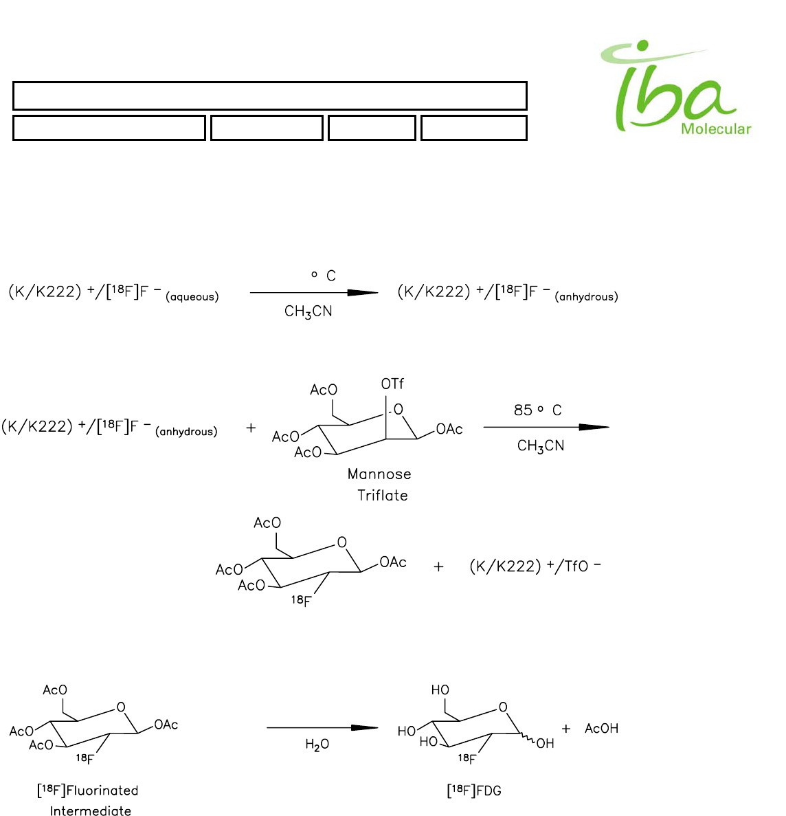
SYNTHERA ™ USER MANUAL
FDG000130 11/17/2006 Rev.: 1 Pg. 55 of 60
An automated self-check process is initiated before synthesis. The self-check process verifies IFP™ configuration,
plumbing integrity, and basic functionality of the processing unit (ex: pumping efficiency, heater operability and other
elements that may adversely affect the process).
The reaction scheme for the production of FDG is represented below:
95
50 oC
+ NaOH
Figure 20
The automated synthesis of FDG is a six-step process consisting of two chemical reactions: a nucleophilic [18F]
fluorination followed by a base-catalyzed hydrolysis (modified Hamacher, et al., 1990). The first reaction incorporates the
18F-label into the organic precursor 1,3,4,6-tetra-O-acetyl-2-O-trifluoromethanesulfonyl-b-D-mannopyranose, or mannose
triflate. The mechanism for this reaction is an SN2 nucleophilic substitution of trifluoromethanesulfonyl group with [18F]
IBA Molecular | Apr 06 Direction: MANXXXX © IBA/All Rights Reserved

SYNTHERA ™ USER MANUAL
FDG000130 11/17/2006 Rev.: 1 Pg. 56 of 60
fluoride ion. The second reaction, the base-catalyzed hydrolysis of the acetyl protecting groups, generates the free
hydroxyl groups of the final drug product. In addition to these reactions, the process includes a drying step, purification
steps, and a product collection step.
Step #1. The first step is extraction of [18F] fluoride ion from the aqueous mixture (target water) delivered from the
cyclotron. To eliminate possible cationic, organic and insoluble in water impurities, this mixture is passed through a
cartridge containing 30 mg of a anion exchange sorbent Accel Plus QMA Sep-Pak™ supplied by Waters Corp. [18F]
fluoride ion is retained on the cartridge while all soluble cationic impurities as well as soluble in water non charged
(organic) substances pass through the column into a waste water (H218O) collection vial. Target water is passed through
the cartridge by means of vacuum applied to the collection vial. Retained on the resin [18F] fluoride ion is eluted with
aqueous acetonitrile solution containing potassium carbonate and equimolar amount of Kryptofix™ 222. Solution is
delivered from reagent vial #1 by means of vacuum applied to the reactor vial. This eluate containing typically 97-99% of
initial activity in a form of potassium [18F] fluoride complex with Kryptofix™ 222 is collected in the reaction vessel.
Step #2 takes place in the reactor vial. Solution from 18F collection vial is delivered into the reaction vessel by means of
aspiration as described above.
Under nitrogen or helium flow, the water/acetonitrile mixture is evaporated leaving potassium [18F] fluoride complex with
Kryptofix 222. Temperature of reaction vessel increases from ambient to 95° C to facilitate evaporation. 2 min. before the
end of evaporation step gas flow is stopped and vacuum is applied to the vessel to complete drying. Total duration of the
evaporation step including vacuum drying of the residue is 12 min.
Hydrogen-bonding solvents significantly lower the reactivity of [18F] fluoride ion. Therefore, it is essential that virtually all
water be removed in this step. Water removal is not considered a chemical reaction, but is accomplished by applying a
combination of heat and vacuum.
Step #3 in the manufacturing process is the production of the [18F] fluorinated intermediate. This involves reaction of the
K+/[18F] F-(anhydrous) prepared in Step #2 with mannose triflate in anhydrous acetonitrile which is added to the reaction
vessel from reagent vial #2 by evacuating reactor vessel.
The [18F] fluoride ion displaces the trifluoromethanesulfonyl, or triflate, leaving group on carbon-2 of mannose triflate,
breaking a carbon-oxygen bond and creating a carbon-[18F] fluorine bond. This displacement occurs via the SN2
mechanism, which leads to complete inversion of stereochemistry at carbon-2 to give the glucose configuration. As a
result of this inversion, no 2-deoxy-2-[18F] fluoro-D-mannose is produced by this synthesis.
Labeling reaction takes place at 85° C. Duration of this step is 3 min. During this time, some mannose triflate either
reacts with [18F] fluoride ion to produce the [18F] fluorinated intermediate (2-deoxy-2-[18F] fluoro-1,3,4,6-tetra-O-acetyl-b-
D-glucopyranose), self-condenses to octa-O-acetyl-beta-sophorose (Engelskirchen, et al., 1989), or polymerizes
(caramelizes). The octa-O-acetyl-beta-sophorose is converted back to glucose during Step #4 (vide infra) and the dark-
colored sugar polymers are removed by adsorption onto the C-18 and Alumina purification cartridge at the final filtration
(Step 6).
Step #4. The next step is evaporation of the acetonitrile yielding a residue containing fluorinated intermediate. This is
achieved by applying a combination of nitrogen flow and then vacuum to the reaction mixture. Temperature during this
step is at 75° C. Duration of this step is 5 min.
Step #5. This step is the base-catalyzed hydrolysis of the residue remaining in the vessel. Sodium Hydroxide solution in
water containing ethanol as stabilizer is added to the reaction vessel from reagent vial #3 and the mixture is heated under
flow of gas at 50°C (temperature of reaction mixture). This step removes the acetyl protecting groups from the [18F]
fluorinated intermediate producing [18F] FDG and unreacted precursor producing L-Glucose. The acetyl groups are
converted to acetic acid and the free hydroxyl groups of [18F] FDG generated by the addition of water across the ester
linkage. Duration of this step is 4 min.
IBA Molecular | Apr 06 Direction: MANXXXX © IBA/All Rights Reserved

SYNTHERA ™ USER MANUAL
FDG000130 11/17/2006 Rev.: 1 Pg. 57 of 60
Step #6. The final step in the process, the purification and delivery of the final product, is accomplished by passing the
hydrolyzed reaction mixture through several successive purification columns. First column contains Strong Cation
Exchange resin (used to remove positively charged complex K+/Kryptofix 222 and neutralize sodium hydroxide and to
remove any remaining ionic species. Attached to this column are basic Aluminum oxide cartridge Sep-Pak™ Plus B (to
adsorb unreacted [18F] fluoride) and finally, C-18 bonded silica cartridge Sep-Pak™ C18 (to retain relatively non-polar
species such as traces of unhydrolyzed [18F] fluorinated intermediate).
Two portions of sterile water for injection (a total of 10.0 ml) from reagent vial #4 are then added to the reaction vessel
and passed through the purification columns to recover as much product as possible. Eluates of the purification column
are filtered through sterile 0.22-micron filter and combined in the final product container. If required, this container prior to
synthesis may be charged with a 0.68 ml of 14.6% sodium chloride (inactive ingredient) to make the final solution isotonic.
Transfer of the final product from the product collection container to final product container completes computer-controlled
preparation.
8.1.5 Operator’s instructions
Synthera ® system is designed to make operation as simple as possible. Although specific training and attention to
details is essential, all manual operations are extremely simple and in many cases designed to prevent mistakes.
To further simplify FDG processing the FDG IFP™ is supplied complete with reagent vials and cartridges. In some cases
reagent vials and cartridges may be supplied in a separate packing to reduce refrigerated storage space needed.
The following steps are required to produce FDG using Synthera ®:
8.1.5.1 Power on and start up
Turn on inert gas supply to the unit; verify the pressure level is between 2 and 2.2 bar absolute.
Turn on compressed air supply and check air pressure min 7 bar gauge.
Turn on electrical power to the unit; switch is located on the bottom of control box. If PC is off or is not connected you
will hear audible signal approximately every second indicating that the unit is functional but not communicating with
PC.
Turn on PC, log on to Windows and start control program
Load FDG method and Check indicators on the screen (see Software section).
Verify that IFP™ holder is in its neutral position and no IFP™ is installed. If not, press red button once to eject the
IFP™. STAY CLEAR OF THE IFP™ HOLDER.
Inspect fluid connectors and actuators, verify that they are undamaged.
8.1.5.2 Preparation
Supplies and materials are described above. Prior to each synthesis these materials and supplies are gathered, checked
and prepared as follows:
8.1.5.2.1 IFP™
Verify IFP™ IFP™ expiration date and labeling. Record IFP™ serial number into batch formulary as required
Remove the IFP™ from packaging. Inspect IFP™ for any damage including missing or loose tubes, deformed
connectors, misplaced valves etc.
Verify that valves are in order (all present and turn easily by hand)
IBA Molecular | Apr 06 Direction: MANXXXX © IBA/All Rights Reserved

SYNTHERA ™ USER MANUAL
FDG000130 11/17/2006 Rev.: 1 Pg. 58 of 60
8.1.5.2.2 Reagents
Verify Reagents expiration date
Record lot number in batch formulary as required
Remove vials from packaging, inspect and record lot numbers as required
8.1.5.2.3 Cartridges
Prepare one of each of the following components from ancillary kit
Alumina B Sep-Pak Plus Cartridge
C18 Sep-Pak Plus Cartridge
QMA Sep-Pak Cartridge
SCX Maxi-Clean cartridge
Water for Injection USP in 30 ml syringe
Ethanol in 10 ml disposable syringe
5 ml of 8.4% solution of NaHCO3 in syringe
Prepare cartridges as follows:
Pass 10 ml of ethanol through the C-18 cartridge
Pass 5 ml of 8.4% NaHCO3 through QMA cartridge
Pass 5 ml of water from 30 ml syringe through QMA cartridge
Pass 5 ml of water through each Al2O3 and SCX cartridges
Pass remaining 10 ml of water through C-18 cartridge
Assemble purification array. Bottom to top: C-18, Al2O3, SCX.
Test purification array for leaks by closing bottom end with a Luer plug and pushing air into the column with a syringe. No
air should leak out between the cartridges.
Prepared cartridges may be kept for one day at room temperature.
8.1.5.2.4 Sterile product container
Assembly of the final product container is normally considered a critical procedure. Typically it is required that it is
performed aseptically within controlled environment. Class A (100 Class in US) is recommended. All materials used in
this procedure are individually packed and sterilized. Introduction of sterile materials into controlled environment,
handling of packed and unpacked items and environment maintenance are not within the scope of this manual.
It is responsibility of the user to establish written procedures in compliance with applicable local regulations and obtain all
necessary regulatory approvals.
The following procedure may be modified to accommodate specific local requirements. Typical procedure is provided.
Prepare one of each of the following components from convenience IFP™:
Membrane Sterilizing Filter, 25 mm, 0.22 um
Membrane Sterilizing Filter, 10 mm, 0.22 um
IBA Molecular | Apr 06 Direction: MANXXXX © IBA/All Rights Reserved

SYNTHERA ™ USER MANUAL
FDG000130 11/17/2006 Rev.: 1 Pg. 59 of 60
Empty Sterile Serum Vial, 30 ml, USP borosilicate glass, Type I
Sterile needles (2 pcs)
Introduce materials into controlled environment following applicable regulatory procedures.
Remove items from their individual packaging and assemble as follows:
Attach needle to each of the two filters
Insert needles into the vial septa
Check that the needles fully penetrate the septa and that tips of two needles are separated by min 5 mm.
8.1.5.2.5 IFP™ assembly
Attach vials and prepared cartridges to the IFP™ as following (clockwise starting on front left position in order of vial
numbers):
Vial #1 – front left position
Vial #2 – back left position
Vial #3 – back right position
Vial #4 – front right position
QMA cartridge (blue band) – front position
C18, Alumina, SCX (bottom to top) – back position
Complete IFP™ assembly as follows:
Check all connections
Move IFP™ holder into its middle position
Install the IFP™ by sliding it from the top into the IFP™ holder
Push IFP™ holder using both hands back as far as it will go
Press two black buttons on the control unit STAY CLEAR FROM THE IFP™ HOLDER – the IFP™ holder will retract
into working position and valves will cycle twice to align actuators
Verify the IFP™ position (must be all the way in) and remove needle support tab
The system is ready for automated process initiation
8.1.5.3 Automated Synthesis
The following steps may be executed at any time not later than 15 min prior to F18 delivery:
Load FDG script (normally already loaded by default)
Press START button on screen. Enter your ID and password and IFP™ serial number for report
The system will initiate self-test. Normally it takes 2-5 min. Observe the test process. If the system pauses at any
step for more than 30 sec it may indicate a problem. See Troubleshooting section
You will hear audible signal after completion of the test step. The active script line will show READY. If F18 delivery
is not ready it is possible to STOP the script at his time. The IFP™ will not be damaged and can be used again.
After test sequence is completed, attach 25 mm filter on the final product container to the outlet tube.
IBA Molecular | Apr 06 Direction: MANXXXX © IBA/All Rights Reserved

SYNTHERA ™ USER MANUAL
FDG000130 11/17/2006 Rev.: 1 Pg. 60 of 60
Close the hot cell door and deliver F18 from cyclotron into the intermediate vial.
When ready to transfer F18 press GREEN button on control unit. Transfer and automated synthesis will commence
immediately
Operator intervention during automated synthesis is possible (if not disabled), however it is strongly recommended to
avoid such intervention. To activate manual controls press PAUSE button on the screen. All manual interventions will be
recorded in the log.
It is also possible to STOP script execution at any time. However, aborted synthesis cannot be resumed, the IFP™
cannot be re-used and product will not be obtained from interrupted synthesis. It is also possible that interruption may
result in escape of radioactive material. Therefore it is strongly recommended not to interrupt the process unless
absolutely necessary.
Upon completion of automated processing the operator will be notified by audible signal.
8.1.5.4 Post Synthesis Operations
Post synthesis operations include removal of the IFP™, and system shut down (if necessary). To remove the IFP™,
press RED button on control unit – STAY CLEAR OF THE IFP™ HOLDER. The IFP™ will fall down into bin provided. If
shielded bin is used the hot cell door may be opened and next IFP™ is installed.
After allowing sufficient time for radioactive material to decay (usually 12-24 hours) used IFP™s can be removed from
storage bin and disposed of in appropriate disposal containers.
To shut down the system first close all applications on PC, then turn control unit power off and turn off gas and air supply.
It is not necessary to turn the system off on a daily basis. However it is always necessary to turn
the system completely off and shut down air and gas supply when servicing the unit.
**
IBA Molecular | Apr 06 Direction: MANXXXX © IBA/All Rights Reserved